
NEAR EAST UNIVERSITY
Faculty of Engineering
Department of Electrical & Electronics Engineering
ELECTRIC MOTOR CONTROL WITH PLC
Graduation Project EE- 400
Student: Hasan Top (980374)
Supervisor: .. ..
Mr. 0. Cemal Ozerdern
Nicosia - 2003
l~ll~.~!I~!~ NEU

I
~~ .... // .~ "\' u ': ',".· '• ~<.,' ~ • ,. ~ l./ // b. -, /i'0r ' \ /' ·~ '~)\
\/ ;i1 7: LIB R {; RY e,,'r /
~
First I want to thank Mr. 6. Cemal Ozerdem to be my advisor. Under his
ACKNOWLEDGEMENT
guidance, I successfully overcome many difficulties and learn a lot about plc. In each
discussion, he explained my question patiently, and I felt my quick progress from his
advices. He always helps me a lot either in my study or my life. I asked him many
question in electronics and automation system and he always answered my questions quickly and in detail.
I also want to thank all my fiends in NEU and all lecturers, Prof., Dr assistants.
Being with them make my 5 years in NEU full of fun. for their valuable advice and motivation to my education.
Finally I want to thank my family, especially my parents, older brothers and
sisters. Without their endless support and love for me, I would never achieve my current
position. I wish my mother lives happily always, and my father in the heaven be proud for me.
ABSTRACT
A programmable control operates by examining the input signals from a process
and carrying out logic· instructions on these input signals, producing output signal to
drive process equipment or machinery. Standard interfaces build into PLC's allow them
to be directly connected to process motor and lamp without the need for intermediate
circuitry or relays.
Through using PLC's it became possible to modify a control system without
having the disconnect or re-route a signal wire. It was necessary to change only the
control program using a keypad or VDU terminal. Programmable controllers also
require shorter installation and commissioning times than do hardwired systems.
Although PLC's are similar to conventional computers in terms of hardware
technology, they have specific features suited to industrial control:
-Rugged, noise immune equipment;
-Modular plug-in construction, allowing easy replacement\addition of units
(input\output);
-Standard input\output connections and signal levels;
-Easily understood programming language (ladder diagram and function chart),
-Ease of programming and reprogramming in-plant.
These features make programmable controllers highly desirable in a wide variety
of industrial-plant and process-control situations.
II

ABSTRACT
A programmable control operates by examining the input signals from a process
and carrying out logic instructions on these input signals, producing output signal to
drive process equipment or machinery. Standard interfaces build into PLC's allow them
to be directly connected to process motor and lamp without the need for intermediate
circuitry or relays.
Through using PLC's it became possible to modify a control system without
having the disconnect or re-route a signal wire. It was necessary to change only the
control program using a keypad or VDU terminal. Programmable controllers also
require shorter installation and commissioning times than do hardwired systems.
Although PLC's are similar to conventional computers in terms of hardware
technology, they have specific features suited to industrial control:
-Rugged, noise immune equipment;
-Modular plug-in construction, allowing easy replacement\addition of units
(input\output);
-Standard input\output connections and signal levels;
-Easily understood programming language (ladder diagram and function chart),
-Ease of programming and reprogramming in-plant.
These features make programmable controllers highly desirable in a wide variety
of industrial-plant and process-control situations.
II

CONTENTS
Acknowledgment Abstract Contents INTRODUCTION CHAPTER 1 1. WHAT IS A PLC? 1.1 PLC HISTORY 1.2 GENERAL PHYSICAL BUILD MECHANISM 1.2.1 Compact PLC's 1.2.2 Modular PLC's
CHAPTER2 2.1 ADV ANT AGES 2.1.1 Accuracy 2.1.2 Data Areas 2.1.3 Logic Control of Industrial Automation 2.1.4 Data object 2.1.5 Flexibility 2.1.6 Communication
2.2 LADDER AND STL PROGRAM 2.2.1 SIEMENS SIMATIC S7-200 PLC SAMPLE PROGRAM
CHAPTER3 3. PROGRAMMABLE CONTROLLER PLC's 3 .1 Introduction 3 .2 Background 3.3 Terminology- PC or PLC 3 .4 PLC Hardware Design 3.4.1 Input/ Output units 3.4.2 Central Processing Unit (CPU) 3 .4.3 Memory 3 .4.4 Memory Size
3.5 Logic instruction set 3.6 Input/output numbering
CHAPTER4 4. TYPES OF PLC 4.1 Small PLC's 4.2 Medium-sized PLC's 4.3 Large PLC 4.4 Remote input/output 4.5 Programming large PLC's 4.6 Developments
CHAPTER 5 5. PROGRAMMING OF PLC SYSTEMS 5.1 Logic instruction sets and graphic programming 5 .1.1 Input/Output Numbering 5.1.2 Negitation - NAND and NOR Gates 5.1.3 Exclusive - OR Gate 5.2 Facilities
III
I II III V 1 1 2 4 4 4 5 5 5 5 5 6 6 6 7 7 9 9 9 10 11 12 12 15 15 16 16 17 19 19 19 21 21 22 22 23 24 24 24 26 26 27 27

5.2.1 Standart PLC Functions 27 5.2.2 Markers I Auxiliary Relays 30 5.2.3 Ghost Contacts 30 5.2.4 Retentive Batery- Backed Relays 30 5.2.5 Optional Functions on Auxiliary Relay 31 5.2.6 Pulse Operation 32 5.2.7 Set and Reset 34 5.2.8 Timers 34 5.2.9 Counters 35 5.2.10 Registers 35 5.2.11 Shift Registers 36 5.3 Arithmetic Instructions 40 5.3.1 BCD Numbering 40 5.3.2 Magnitude Comparison 42 5.3.3 Addition and Subtraction Instructions 42
CHAPTER 6 43 6. LADDER PROGRAM DEVELOPMENT 43 6.1 Software Design 43 6.1.1 System Function 43 6.2 Program Structure 4 7 6.3 Further Sequential Control Techniques 48 6.4 Limitation of Ladder Programming 49 6.4.1 Advanced Graphic Programming Languages 49 6.4.2 Workstations 50
CHAPTER 7 51 7.CHOOSINGTNSTALLATION & COMMISSIONING OF PLC SYSTEM 51 7.1 Feasibility Study 51 7.2 Design Procedure for PLC System 52 7.2.1 Choosing a Programmable Controller 52 7 .2.2 Size and Type of PLC System 52 7 .2.3 I I O Requirements 53
7 .3 Installation 55 7.4 Testing and Commissioning 56 7.4.1 Software Testing and Simulation 57 7.4.2 Installing and Running the User Control Program 59
CHPATER 8 61 8. LADDER AND STL PROGRAM 61 8.1 SIEMENS SIMATIC S7-200 PLC MOTOR CONTROL PROGRAM 61
CONCLUSION 67 REFERENCES 68
IV

INTRODUCTION
Programmable controllers are generally programmed in ladder diagram ( or
"relay diagram") which is nothing but a symbolic representation of electric circuits.
Symbols were selected that actually looked similar to schematic symbols of electric
devices, and this has made it much easier for electricians to switch to programming PLC
controllers. Electrician who has never seen a PLC can understand a ladder diagram.
The need for low cost, versatile and easily commissioned controllers has resulted
m the development of programmable-control systems standard units based on a
hardware CPU and memory for the control of machines or processes. Originally
designed as a replacement for the hard-wired relay and timer logic to be found in
traditional control panels, PLC's provides ease and flexibility of control based on
programming and executing simple logic instructions. PLC's have internal functions
such as timers, counters and shift registers, making sophisticated control possible using
even the smallest PLC.
V
CHAPTER 1
I.WHAT IS A PLC?
A programmable logic controller (PLC) is a device that was invented to replace
the necessary sequential relay circuits for machine control. The PLC works by looking
at its inputs and depending upon their state, turning on I off its outputs. The user enters a
program, usually via software, that gives the desired results.
PLC's are used in many real world applications. If there is industry present,
changes are good that there is a PLC present. If you are involved in machining,
packaging material handling, and automated assembly or countless other industries you
are probably already using them. If you are not, you are wasting money and time.
Almost any application that needs some type of electrical control has a need for PLC.
For example, let's assume that when a switch turned on, we want tum on a
solenoid for 5 seconds and then tum it off regularly of how long the switch is on. We
can do this with a simple external timer. But what will happen if the process included 10
switches and solenoids? We would need 10 external timers. What will happen if the
process also needed to count how many times the switches individually turned on? We would need a lot of external counters.
As you see, if the process becomes more complicated, then we have to use a
device the simplify that. We use PLC for this process. We can program the PLC to
count its inputs and tum the solenoids for the specified time.
This site gives you enough information to be able to write programs for more
complicated then the simple than above. We will take a look at what is considered to be
the 'top 20' PLC instructions. It can be safely estimated that with affirm
understanding of these instructions, that just one of them can solve more than 80 % of
the applications in existence.
1

1.1 PLC HISTORY
In the late 1960's PLC's were first introduced. The primary reason for designing
such a device was eliminating the large cost involved in replacing the complicated relay
based machine control systems. Bedford Associates (Bedford, MA) proposed something
called a modular digital controller (MODICON) to a major US car manufacturer. Other
companies at the time proposed computer based upon the PDP - 8. The MOD ICON 084
brought the world's first PLC into commercial production.
When production requirements changed so did the control system. This becomes
very expensive when the change is frequent. Since relays are mechanical devices they
also have a limited lifetime that required strict adhesion to maintenance schedules.
Troubleshooting was also quite tedious when so many relays are involved. Now picture
a machine control panel that included many, possible hundreds or thousands, of
individual relays. The size could be mind-boggling. How about the complicated initial
wiring of so many individual devices! These relays would be individually wired
together in a manner that would yield the desired outcome.
These new controllers also had to be easily programmed by maintenance and
plant engineers. The lifetime had to be long and programming changes easily
performed. The also had to survive the harsh industrial environment. That's a lot to ask!
The answers were to use a programming technique most people were already familiar
with and replace mechanical parts with solid-state ones.
In the mid70's the dominant PLC techniques were sequencer state machines and
the bit-slice based CPU. The AMD 2901 and 2903 were quite popular in MODICON
and A-B PLC's. Conventional microprocessors lacked the power to quickly solve PLC
logic in all but the smallest PLC's. As conventional microprocessors evolved, larger and
larger PLC's were being based upon them. However, even today some are still based
upon the 2903. MODICON has yet the build a faster PLC then their 984A/B/X, which
was based upon the 2901.
Communications abilities began to appear in approximately 1973. The first such
system was MODICON's MODBUS. The PLC could now talk to other PLC's and they
could be far away from the actual machine they were controlling. They could also now
be used to send and receive varying voltages to allow them to enter the analogue world.
Unfortunately, the lack of standardization coupled with continually changing
2
technology has made PLC communications a nightmare of incompatible protocols and
physical networks.
The 80's saw an attempt to standardize communications with General Motor's
manufacturing automation protocol. It was also a time for reducing the size of the PLC
and making them software programmable through symbolic programming on personnel
computers instead of dedicated programming terminals or handheld programmers.
The 90's have seen a gradual reduction in the introduction new protocols, and
the modernization of the physical layers of same of the more popular protocols that
survived the l 980's. The latest standard has tried to merge PLC- programming
languages under one international standard. We now have PLC's that are programmable
in function block diagrams, instruction list, C and structured text all at the same time!
PC's are also being used to replace PLC's in some applications. The original company
who commissioned the MODICON 084 has actually switched to a PC based control
system.
3

1.2 GENERAL PHYSICAL BUILD MECHANISM
PLC's are separated into two according to their building mechanisms.
1.2.1 Compact PLC'S
Compact PLC's are manufactured such that all units forming the PLC are placed
in a case. They are low price PLC with lower capacity. They are usually preferred by
small . or medium size machine manufacturers. In some types compact enlargement
module is present.
1.2.2 Modular PLC's
They are formed by combining separate modules together in a board. They can
have different memory capacity, I IO numbers, power supply up to the necessary limits.
Some examples: SIEMENS S5-115U, SIEMENS S?-200, MITSUBISHI PC40,
TEXAS INSTRUMENT PLC'S, KLOCKNER-MOELLER PS316, OMRON C200H.
4
CHAPTER2
2.1 ADV ANT AGES
2.1.1 Accuracy
In relay control systems logical knowledge's carries in electro-mechanical
contactors, they can lose data because of mechanical errors. But PLC's are
microprocessor-based system so logical data are carried inside the processor, so that
PLC's are more accurate than relay type of controllers.
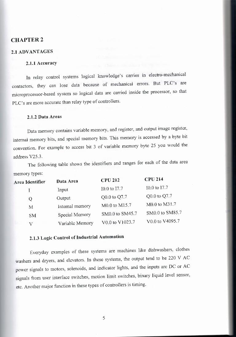
2.1.2 Data Areas
Data memory contains variable memory, and register, and output image register,
internal memory bits, and special memory bits. This memory is accessed by a byte bit
convention. For example to access bit 3 of variable memory byte 25 you would the
address V25.3. The following table shows the identifiers and ranges for each of the data area
memory types:
Area Identifier Data Area CPU 212 CPU 214
I Input 10.0 to 17.7 10.0 to 17.7
Q Output QO.O to Q7.7 QO.O to Q7.7
M Internal memory MO.Oto M15.7 MO.Oto M3 l.7
SM Special Memory SMO.O to SM45.7 SMO.O to SM85.7
V Variable Memory VO.Oto V1023.7 VO.Oto V4095.7
2.1.3 Logic Control of Industrial Automation
Everyday examples of these systems are machines like dishwashers, clothes
washers and dryers, and elevators. In these systems, the output tend to be 220 V AC
power signals to motors, solenoids, and indicator lights, and the inputs are DC or AC
signals from user interface switches, motion limit switches, binary liquid level sensor,
etc. Another major function in these types of contro.llers is timing.
5
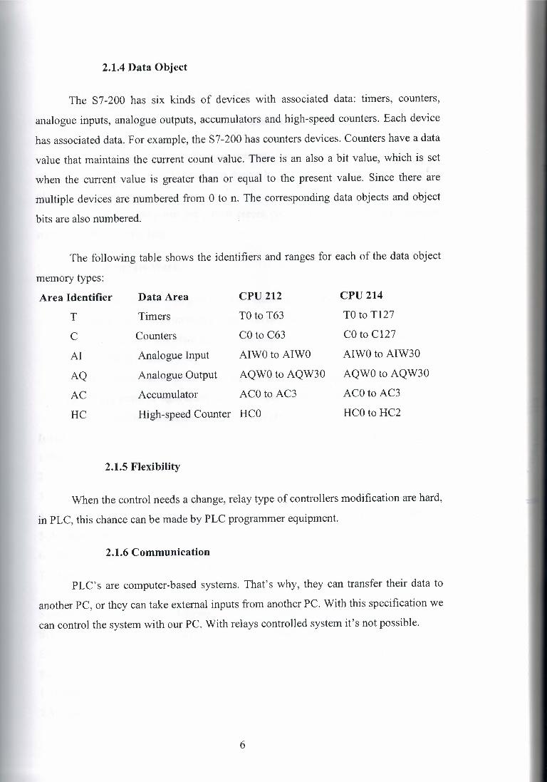
2.1.4 Data Object
The S7-200 has six kinds of devices with associated data: timers; counters,
analogue inputs, analogue outputs, accumulators and high-speed counters. Each device
has associated data. For example, the S7-200 has counters devices. Counters have a data
value that maintains the current count value. There is an also a bit value, which is set
when the current value is greater than or equal to the present value. Since there are
multiple devices are numbered from O to n. The corresponding data objects and object
bits are also numbered.
The following table shows the identifiers and ranges for each of the data object
memory types:
Area Identifier Data Area CPU 212 CPU 214
T Timers TO to T63 TO to T127
C Counters CO to C63 CO to C127
AI Analogue Input AIWO to AIWO AIWO to AIW30
AQ Analogue Output AQWO to AQW30 AQWO to AQW30
AC Accumulator ACO to AC3 ACO to AC3
HC High-speed Counter HCO HCOto HC2
2.1.5 Flexibility
When the control needs a change, relay type of controllers modification are hard,
in PLC, this chance can be made by PLC programmer equipment.
2.1.6 Communication
PLC's are computer-based systems. That's why, they can transfer their data to
another PC, or they can take external inputs from another PC. With this specification we
can control the system with our PC. With relays controlled system it's not possible.
6

2.2 LADDER AND STL PROGRAM
2.2.1 SIEMENS SIMATIC S7-200 PLC SAMPLE PROGRAM
In this program, Cotton to filament converts during the war. While cottons are to
comb by the machine, separate operation during by the war cotton pieces are to gather
of under the machine. This p:i;ogram purposes are cotton pieces convert to back. With this program
cotton cost decrease the less.
Program Work
1. For the vacuum if we give the start, motor is start to work.
2. After the 15 s machines are made with raw and once vacuum.
3. One machine and other machine between passed time 2 s, and vacuum time
for the all machine 8 s.
4. If someone machine not works passed to other machine.
5. If fire alarm or tight alarm gives, fan motor and all other operation stop. For
the machines works are until push the button machines are not work. Output
1- Fan motor start
2- Machine 1 vacuum
3- Machine 2 vacuum
4- Machine 3 vacuum
5- Fire alarm
6- Tight alarm
In}!ut
1- Start
2- Stop
3- Reset
4- Machine work 1
5- Machine work 2
6- Machine work 3
7- Tight
Symbol name Address
Start EO.O
Stop E0.1
Reset E0.2
I .Machine work E0.3
2.Machine work E0.4
Note
Start button
Stop button
Reset button
If 1. Machine Work sends to sign
If 2. Machine Work sends to sign
7

3. Machine work E0.5 If 3. Machine Work sends to sign
Fire E0.6 If the fire alarm is coming
Tight E0.7 Fan motor has tight
Start-Output AO.O Fan motor is start
Vacuum I AO.I I .Machine vacuum valve
Vacuum 2 A0.2 2.Machine vacuum valve
Vacuum 3 A0.3 3 .Machine vacuum valve
Fire Alarm A0.4 If the fire sensor signal coming
Tight Alarm A0.5 To throw the motor tight
Cleanliness Air valve A0.6 Tube Cleanliness valve
Relay of vacuum T32 After start vacuum relay
Vacuum time T33 Valves are Vacuum Time
Stop Time T34 Between of valves Stop time
Counter 0 zo l.Machine Valve Work Counter
Counter I ZI 2.Machine Valve Work Counter
Counter 2 Z2 3.Machine Valve Work Counter
Counter 3 Z3 Circle Reset
Jump Output A7.1 Machines are not jump
8
CHAPTER3
3. PROGRAMMABLE CONTROLLER PLC's
3.1 Introduction
The need for low cost, versatile and easily commissioned controllers has resulted
m the development of programmable-control systems standard units based on a
hardware CPU and memory for the control of machines or processes. Originally
designed as a replacement for the hard-wired relay and timer logic to be found in
traditional control panels, PLC's provides ease and flexibility of control based on
programming and executing simple logic instructions. PLC's have internal functions
such as timers, counters and shift registers, making sophisticated control possible using
even the smallest PLC.
A programmable control operates by examining the input signals from a process
and carrying out logic instructions on these input signals, producing output signal to
drive process equipment or machinery. Standard interfaces build into PLC's allow them
to be directly connected to process actuators and transducers (pumps and valves)
without the need for intermediate circuitry or relays.
Through using PLC's it became possible to modify a control system without
having the disconnect or re-route a signal wire. It was necessary to change only the
control program using a keypad or VDU terminal. Programmable controllers also
require shorter installation and commissioning times than do hardwired systems.
Although PLC's are similar to conventional computers in terms of hardware
technology, they have specific features suited to industrial control:
-Rugged, noise immune equipment;
-Modular plug-in construction, allowing easy replacement\addition of units
(input\output);
-Standard input\output connections and signal levels;
-Easily understood programming language (ladder diagram and function chart),
-Ease of programming and reprogramming in-plant.
These features make programmable controllers highly desirable in a wide variety
of industrial-plant and process-control situations.
9
3.2 Background
The programmable controller was initially conceived by a group of engineers
from General Motors in 1968, where an initial specification was provided: the controller
must be:
1- Easily programmed and reprogrammed, preferably in-plant to alter its sequence
of operations.
2- Easily maintained and repaired- preferably using plug-in modules.
3- (a)-More reliable in plant environment.
(b )-Smaller than it is relay equivalent.
4- Cost competitive, with solid-state and relay panels than in use.
This provoked a keen interest from engineers of all disciplines in how to PLC
could be used for industrial control. With this came demands for additional PLC
capabilities and facilities, which were rapidly implemented as the technology became
available. The instruction sets quickly moved from simple logic instructions to include
counters, timers and shift registers, than onto more advanced mathematical functions on
the machines. Developments hardware were also occurring, with larger memory and
greater numbers of input I output points featuring on new models. In 1976 became
possible to control remote I I O racks, where large numbers of distant I I O points were
monitored updated via a communications link, often several hundred meters from the
main PLC. The Allan-Bradley Corporation in America introduced a microprocessor
based PLC in 1977. It was based on an 8080 microprocessor but used an extra processor
to handle bit logic instruction at high speed.
The increased rate of application of programmable controllers within industry
has encouraged manufacturers to develop whole families of microprocessor-based
systems having various levels of performance. The range of available PLC's now
extends from small self-contained units with 20 digital I I O points and 500 program
steps, up to modular systems with add-on function modules:
-Analogue I/0;
-PID control (proportional, integral and derivative terms);
-Communications;
-Graphics display;
-Additional I/0;
-Additional memory.
10
-
This modular approach allows the expansion or upgrading of a control system
with minimum cost and disturbance.
Programmable controllers are developing at a virtually the same pace as
microcomputers, with particular emphasis on small controllers, positioning\numeric
control and communication networks. The market for small controllers has grown
rapidly since the early 1980's when a number of Japanese companies introduced very
small, low cost units that were much cheaper than others available at that time. This
brought programmable controllers within the budget of many potential users in the
manufacturing and process industries, and this trend continues with PLC's offering
ever-increasing performance at ever-decreasing cost.
The Mitsubishi F40 PLC is a typical example of a modem small PLC, providing
40 I I O points, 16 timers and counters, plus other functions. The controller uses a
microprocessor and has 890 RAM locations fur user programs. The 24-input channels
of the F40 operate at 24 V d.c. Whilst 16 outputs may be 24 V d.c. or 240 V a.c. to
provide easy interfacing to industrial equipment.
3.3 Terminology-PC or PLC
There are several different terms used to describe programmable controllers,
most referring to the functional operation of the machine in question:
PC programmable controller
PLC programmable logic controller
PBS programmable binary system
By their nature these terms tend to describe controllers that normally work in a
binary environment. Since all but the smallest programmable controllers can now be
equipped to process analogue inputs and outputs these labels are not representative of
their capabilities. For these reason the overall term programmable controller has been
widely adopted to describe the family of freely programmable controllers. However, to
avoid confusion with the personal computer PC, this text uses the abbreviation PLC for
programmable (logic) controller.
11
3.4 PLC Hardware Design
Programmable controllers are purpose-built computers consisting of three
functional areas:
-Processing:
-Memory:
-Input I output:
Input conditions to the PLC are sensed and than stored in the memory, where the
PLC performs the programmed logic instructions on these input states. Output
conditions are then generated to drive associated equipment. The action taken depends
totally on the control program held in memory.
In smaller PLC these functions are performed by individual printed circuit cards
within a single compact unit, whilst larger PLC's are constructed on a modular basis
with function modules slotted in to the backplane connectors of the mounting rack.
This allows simple expansion of the system when necessary. In both these cases
the individual circuit board are easily removed and replaced, facilitating rapid repair of
the system should faults develop.
In addition a programming unit is necessary to download control programs to
the PLC memory.
3.4.1 Input output I units
Most PLC'S operate internally at between 5 and 15 V d.c. (common TTL and
CMOS voltages), whilst process signals much greater, typically 24 V d.c. to 240 V a.c.
at several amperes.
The I I O units form the interface between the microelectronics of the
programmable controller and real world outside, and must therefore provide all,
necessary signal conditioning and isolation functions. This often allows a PLC to be
directly connected to process actuators and transducers (pumps and valves) without the
need for intermediate circuitry and relays.
To provide this signal conversion programmable controllers are available with a
choice of input I output units to suit different requirements.
12

For example;
Inputs 5 V (TTL level) switched I/ P
24 V switched I/ P
110 V switched I/ P
240 v switched I/ P
24 V 100 mA switched 0/ P
110 V lmA
240 V 1 A a.c. ( triac )
240 V 2 A a.c. (relay)
It is standard practice for all I/0 channels to electrically isolated from the
Outputs
controlled process, using opto-isolator circuits on the I/0 modules. An opto-isolator
circuit consists of a light emitting diode and a phototransistor, forming an opto coupled
pair that allows small signals to pass through, but will clamp any high voltage spikes or
surges down to the same small level. This provides protection against switching
transients and power-supply surges, normally up to 1500V.
In small self contained PLC's in which all I/ 0 points are physically located on
the one casing, all inputs will be of one type ( e.g. 24 V) and the same for outputs ( e.g.
all 240 V triac ). This is because manufacturers supply on the standard function boards
for economic reasons. Modular PLC's have greater flexibility of I/ 0, however, since
the user can select from several different types and combinations of input and output
modules.
In all cases the input/output units are designed with the aim of simplifying the
connections of process transducers and actuators to the programmable controller. For
these purpose all PLC'S are equipped with standard screw terminals or plugs on every
1\0 point, allowing the rapid and simple removal and replacement of a faulty I/ 0 card.
Every input\output point has a unique address or channel number, which is using during
program development to specify to monitoring of an input or the activating of a
particular output within the program. Indication of the status of input\output channels is
provided by light-emitting diode (LED's) on the PLC or I/ 0 unit, making it simple to
check the operation of process inputs and outputs from the PLC itself.
13

Programmable logic controller
PLC !F201 ~ :::::-1 12 1/P I Process A
II · 240 V a.c. 2 A II
Graphic I II requirements II 8 0/P II orogramme1 II II
I 240 V, 2 A II
II rated outputs II II (relay or triac) II
e] II II I Program A II If If II If II If ,, If II
(Removed after II 11 programming) II ,,
I
I j ~lnlmal : interfac 1...--- PLC (F40) - I Process B
24 1/P 24 V d.c. requirements
16 O/P 24 V d.c. transistor outputs
Program B
PLC Control. Easily programmed/altered by the USER. Used for switched input/output.
input from microprocessor
Light emitting diode
r--------------, ~~~~~'~- I I r-~-'-~~~~-
0 pt O · coupler
~ ~
, Photo transistor
1 Electricalisolation , 1- .J
Figure 6.5 Opto-isolator circuit
14
Output to peripheral in process
3.4.2 Central Processing Unit (CPU)
The CPU controls and supervises all operations within the PLC, carrying out
programmed instructions stored in memory. An internal communications highway or
bus system, carries information to and from the CP, memory and I/ 0 units, under
control of the CPU. The CPU is supplied with a clock frequency by an external quartz
crystal or RC oscillator, typically between 1 and 8 megahertz depending on the
microprocessor used and the area of application.
- The clock determines the operating speed of the PLC and provides
timing\synchronization for all elements in the system. Virtually all modem
programmable controllers are microprocessor based using a micro as a system CPU.
Some larger PLC's also employ additional microprocessor to control complex, time
consuming functions such as mathematical processing, three terms PID control.
3.4.3 Memory
(a) For program storage all modem programmable controllers use
semiconductor memory devices such as RAM read\write memory, or
a programmable read-only memory of the EPROM or EEPROM families.
In the virtually all cases RAM is used for initial program development and
testing, as it follows changes to be easily made in program. The current trend is to be
providing CMOS RAM because of it is very low power consumption, to provide battery
back-up to this RAM in order to maintain the contents when the power is removed from
the PLC system. This battery has a lifespan of at least one year before replacement is
necessary, or alternatively a rechargeable type may be supplied with the system being
recharge whenever the main PLC power supply is on.
This feature makes programs stored in RAM virtually permanent. Many users
operate their PLC systems on this basis alone, since it permits future program alterations if and when necessary.
After a program is fully developed and tested it may be loaded (blown) into a
PROM or EPROM memory chip, which are normally cheaper than RAM devices.
PROM programming is usually carried out with a special purpose programming unit,
although many programmable controllers now have this facility built-in, allowing
15
3.5 Logic instruction set
programs in the PLC RAM to be down loaded into a PROM IC placed in a socket
provided on the PLC itself.
(b) In addition to program storage, a programmable controller may
require memory for other functions:
1- Temporary buffer store for input\output channels status- I/ 0 RAM
2- Temporary storage for status of internal function (timers, counters,
marker relays)
Since these consist of changing data they require RAM read\write memory,
which may be battery-backed in sections.
3.4.4 Memory size
Smaller programmable controllers normally have a fixed memory size, due in
part to the physical dimensions of the unit. This varies in capacity between 300 and
1000 instructions depending on the manufacturer. This capacity may not appear large
enough to be very useful, but it has been estimated that 90 % of all binary control tasks
can be solved using less than 1000 instructions, so there is sufficient space to meet most
users needs. Larger PLC's utilize memory modules of between lK and 64K in size, allowing
the system to be expanded by fitting addition RAM or PROM memory cards to the PLC
rack. As integrated circuit memory costs continue to fall, the PLC manufacturers are
providing larger program memories on all products.
The most common technique for programming small PLC's is to draw s ladder
diagram of the logic to be used, and then convert this in to mnemonic instructions,
which will be keyed in to programming panel attached to the programmable controller.
These instructions are similar in appearance to assembly-type codes, but refer to
physical inputs, outputs and functions within the PLC itself.
The instruction set consists of logic instructions (mnemonics) that represent the
actions that may be performed within a given programmable controller. Instructions sets
16
vary between PLC's from different manufacturers, but are similar in terms of the
control actions performed.
Because the PLC logic instruction set tends to be small, it can be quickly
mastered and used by control technicians and engineers.
Each program instructions are made up of two parts: a mnemonic operation
component or opcode, and an address or operand component that identifies particular
elements
(E.g. outputs) within the PLC.
For example;
Opcode
OUT
Device symbol
Operand
Y430
Identifier
Here the instruction refers to output (Y) number 430
3.6 Input\output numbering
These instructions are used the program logic control circuits that have been
designed in ladder diagram form, by assigning all physical inputs and outputs with an
operand suitable to the PLC being used. The numbering system used differs between
manufacturers, but certain common terms exist. For example, Texas instrument and
Mitsubishi use the symbol X to represent inputs, and Y to label outputs.
Programmable Controller
Inputs X Outputs Y
A range of addresses will be allocated to particular elements: for example
17

Mitsubishi F40 PLC: 24 inputs: X400-407, 410-413
X500- 507, 510- 513
16 Outputs: Y430-437
Y530- 537
Inspections of these numbers ranges will reveal that there is no overlap of
addresses between functions; that is, 400 must be an input, 533 must be an output. Thus
for these programmable controllers the symbol X or Y is redundant, being used purely
for the benefit of the user, who is unlikely to remember what element 533 represents.
However, for many PLC's both parts of the address are essential, since the I\O number
ranges are identical. For example the Klockner-Moeller range of controllers:
Sucos PS 21 PLC: 8 inputs IO to 7, etc. 8 Outputs QO to 7, etc
X400 X401
Y430
Y430
Y431
Figure 7.7 Ladder Diagram
To program the ladder diagram given in figure 7.7, the following code would be
written, and then programmed in to a keypad or terminal.
1 LD X400 start a rung with a normally open contact
2 ORY 430 connect a normally open contact in parallel
3 ANI X401 connect a normally closed contact in series
4 OUT Y 430 drive an output ~hannel
5 OUT Y 431 drive another channel
6 END end of program-return to start
Notice the contact Y 430 that forms a latch across X400. The Y contact is not a
physical element, but is simulated within the programmable controller and will operate
in unison with the output point Y 430. The programmer may create as many contacts
associated with an output as necessary.
18

CHAPTER4
4. TYPES OF PLC
The increasing demand from industry for programmable controllers that can be
applied to different forms and sizes of control tasks has resulted in most manufacturers
producing a range of PLC's with various levels of performance and facilities.
Typical rough definitions of PLC size are given in terms of program memory
size and the maximum number of input\output points the system can support. Table 7.1
gives an example of these categories.
Table 4.1 Categories of PLC
PC size Max I \ 0 points Use memory size
Small 40 I 40 lK
Medium 128 I 128 4K
Large > 128 I> 128 >4K
However, to evaluate properly any programmable controller we must consider
many additional features such as its processor, cycle time language facilities, functions,
and expansion capabilities.
A brief outline of the characteristics of small, medium of large programmable
controller is given below, together with typical applications.
4.1 Small PLC's
In general, small and 'mini' PLC's are designed as robust, compact units, which
can be mounted on or beside the equipment to be controlled. They are mainly used the
replaced hard-wired logic relays, timers, counters. That control individual items of plant
or machinery, but can also be used to coordinate several machines working in
conjunction with each other.
Small programmable controllers can normally have their total I/ 0 expanded by
adding one or two I/ 0 modules, but if any further developments are required this will
19

often mean replacement of the complete unit. This end of the market is very much
concerned with non-specialist and users, therefore ease of programming and a 'familiar'
circuit format are desirable. Competition between manufacturers is extremely fierce in
this field, as they vie to obtain a maximum share in this partially developed sector of the
market.
A single processor is normally used, and programming facilities are kept a fairly
basic level, including conventional sequencing controls and simple standard functions:
e.g. timers and counters. Programming of small PLC's is by way oflogic instruction list
(mnemonics) or relay ladder diagrams.
Program storage is given by EPROM or battery-backed RAM. There is now a
trend towards ,EEPROM memory with on-board programming facilities on several
controllers.
Table 4.2 Features of a typical small PLC - Mitsubishi F20
Electrical: 240 V a.c. supply;
24 V d.c. on-board for input requirements;
12 input, 8 output points;
LED indicators on all I/ 0 points;
All I\O Opto-isolated
Choice of output: Relay(240 V 2 a rated)
Triac (240 V 1 A rated)
Transistor (24 V d.c. 1 A)
320- step memory (CMOS battery-backed RAM)
Programming: Ladder logic or instruction set using hand-held or graphic LCD
programmer, with editor, test and monitor facilities;
8 counters, range 1-99 ( can be cascaded)
8 timers, range 0.1-99s ( can be cascaded)
Facilities:
64 markers\auxiliary relays; can be used individually or in blocks
forming shift registers;
Special function relays;
Jump capability.
20

4.2 Medium-sized PLC'S
In this range modular construction predominates with plug-in modules based
around the Eurocard 19 inch rack format or another rack mounting system. This
construction allows the simple upgrading or expansion of the system. This construction
allows the simple upgrading or expansion of the system by fitting additional I/ 0 cards
in to the cards into the rack, since most rack, systems have space for several extra
function cards. Boards are usually 'ruggedized' to allow reliable operation over a range
of environments.
In general this type of PLC is applied to logic control tasks that can not be met
by small controllers due to insufficient I\O provision, or because the control task is
likely to be extended in the future. This might require the replacement of a small PLC,
where as a modular system can be expanded to a much greater extent, allowing for
growth. A medium-sized PLC may therefore be financially more attractive in the long
term.
Communications of a single and multi-bit processor are likely within the CPU.
For programming, standard instructions or ladder and logic diagrams are available.
Programming is normally carried out via a small keypad or a VDU terminal. If different
sizes of PLC are purchased from a single manufacturer, it is likely that programs and
programming panels will be compatible between the machines.
4.3 Large PLC
Where control of very large numbers of input and output points is necessary and
complex control functions are required, a large programmable controller is the obvious
choice. Large PLC's are designed for use in large plants or on large machines requiring
continuous control. They are also employed as supervisory controllers to monitor and
control several other PLC's or intelligent machines. e.g. CNC tools.
Modular construction in Eurocard format is standard, with a wide range of
function cards available including analogue input output modules. There is a move
towards 16-bit processor, and also multi-processor usage in order to efficiently handle a
large range of differing control tasks.
For example;
• 16-bit processor as main processor for digital arithmetic and text handling.
• Single-bit processor as co-or parallel processor for fast counting, storage etc.
21
• Peripheral processor for handling additional tasks which are time-dependent
or time-critical, such as:
Closed-loop (PID) control
Position controls
Floating-point numerical calculations
Diagnostic and monitoring
Communications for decentralized
Remote input\output racks.
This multi-processor solution optimizes the performance of the overall system as
regards versatility and processing speed, allowing to PLC to handle very large programs
of 100 K instructions or more. Memory cards can now provide several megabytes of
CMOS RAM or EPROM storage.
4.4 Remote input\output
When large numbers of input I output points are located a considerable distance
away from the programmable controller, it is uneconomic to run connecting cables to
every point. A solution to this problem is to site a remote I/ 0 unit near to the desired
I/ 0 points. This acts as a concentrator to monitor all inputs and transmit their status
over a single serial communications link to the programmable controller. Once output
signals have been produced by the PLC they are feedback along the communications
cable to the remote I/ 0 unit, which converts the serial data into the individual output
signals to drive the process.
4.5 Programming large PLC's
Virtually any function can be programmed, using the familiar ladder symbols via
a graphics terminal or personal computer. Parameters are passed to relevant modules
either by incorporating constants in to the ladder, or via on screen menus for that
module.
There may in addition be computer-oriented languages, which allow
programming of function modules and subroutines.
There is progress towards standardization of programming languages; with
programs becoming easier to over-view through improvement of text handling, hand
22
improved documentation facilities. This is assisted by the application of personal
computers as workstations.
4.6 Developments
Present trends include the integration of process data from a PLC into
management databases, etc. This allows immediate presentation of information to those
involved in scheduling, production and planning.
The need to pass process information between PC's and PLC sand other devices
within a automated plants has resulted in the provision of a communications capability
on all but the smallest controller. The development of local area networks (LAN) and in
particular the recent MAP specification by General Motors (manufacturing automation
protocol) provides the communication link to integrate all levels of control systems.
23

CHAPTERS
5. PROGRAMMING OF PLC SYSTEMS
In the previous chapter we were introduced to logic instructions sets for
programming PLC systems. The complete sets of basic logic instruction for two
common programmable controllers are given below. Note the inclusion in these lists of
additional instructions ORB and ANB to allow programming of more complex, multi
branch circuits. The use of all these instructions and others is dealt with in this chapter.
Some typical instruction sets for Texas instruments and Mitsubishi PLC's are given in table 8.1
Table 5.1 Typical logic instruction sets
Texas Instrument Mitsubishi A series Mnemonic Action Mnemonic Action
STR Store LD Start rung with an open contact
OUT Output OUT Output AND Series components AND Series elements OR Parallel components OR Parallel elements NOT Inverse action .. I As for not
ORB Or together parallel branches
ANB And together series circuit blocks
5.1 Logic instruction sets and graphic programming
In the last chapter we introduced logic instructions as the basic programming
language for programmable controllers. Although logic instructions are relatively easy
24
to learn and use, it can be extremely time-consuming to check and relate a large coded
program to actual circuit function.
In addition, logic instructions tend to vary between different types of PLC.
In a factory or plant is equipped with a range of different controllers (a common
situation), confusion can result over differences in the instruction sets.
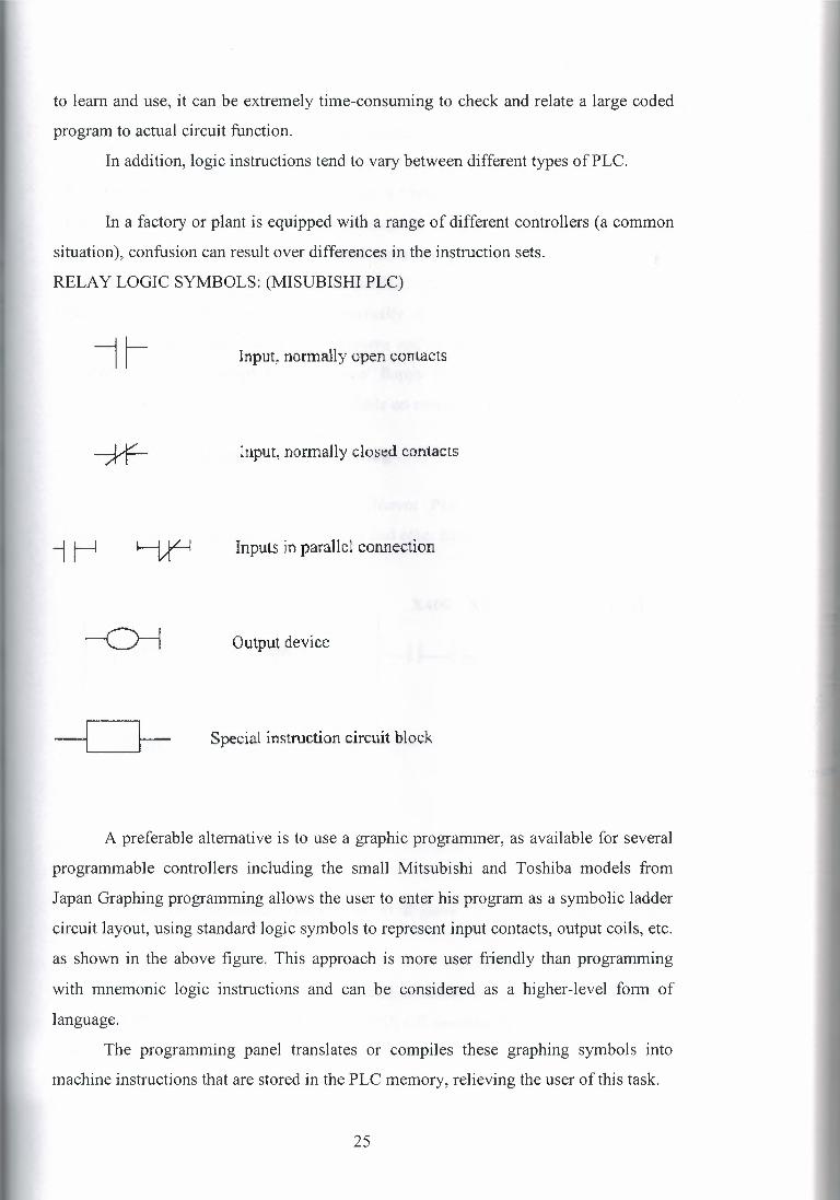
RELAY LOGIC SYMBOLS: (MISUBISHI PLC)
11 Input, normally open contacts
Input, normaJly closed contacts
Inputs in parallel connection
Output device
Special instruction circuit block
A preferable alternative is to use a graphic programmer, as available for several
programmable controllers including the small Mitsubishi and Toshiba models from
Japan Graphing programming allows the user to enter his program as a symbolic ladder
circuit layout, using standard logic symbols to represent input contacts, output coils, etc.
as shown in the above figure. This approach is more user friendly than programming
with mnemonic logic instructions and can be considered as a higher-level form of
language.
The programming panel translates or compiles these graphing symbols into
machine instructions that are stored in the PLC memory, relieving the user of this task.
25
Different types of graphing programmer are normally used for each family of
programmable controller, but they all support similar graphic circuit conventions.
Smaller, hand-held panels are common for the small to medium-sized PLC's although
the same programming panel often used as a 'field programmer' for these and larger
PLC'S in the sane family. However, the majority of graphic programming for larger
systems is carried out on terminal sized units. Some of these units are also semi
portable, and may be operated alongside the PLC system under commissioning or test in
plant. In addition to screen displays, virtually all graphic-programming stations can
drive printers for hard copy of the programs and\or status information, plus program
storage via battery-backed RAM or tape/ floppy disk. The facility to load resident
programs into EPROM IC'S may be available on more expensive units.
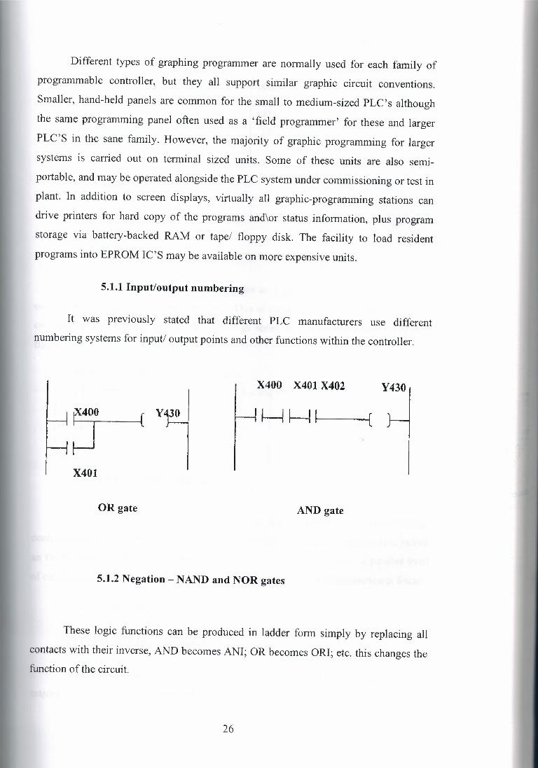
5.1.1 Input/output numbering
It was previously stated that different PLC manufacturers use different
numbering systems for input/ output points and other functions within the controller.
X400 X401 X402 Y430
X401
OR gate AND gate
5.1.2 Negation -NAND and NOR gates
These logic functions can be produced in ladder form simply by replacing all
contacts with their inverse, AND becomes ANI; OR becomes ORI; etc. this changes the function of the circuit.
26

X400 X401 Y430
Y4)0
( J
NOR gate NAND gate
5.1.3 Exclusive - OR gate
This different form the normal OR gates as it gives an output of 1 when either
one input or the other is on, but not both. This is comparable to two parallel circuits,
each one with make and one break contact in series as shown in exclusive OR gate
figure.
X400 X401 Y430
X4D0 X401
EXCLUSIVE - OR gate
Note the use of an ORB instruction in this example. The programmable
controller reads the first two instructions, then finds another rung start instruction before
an OUT instruction has been executed. The CPU therefore realizes that a parallel form
of circuit exists and reads the subsequent instructions until an ORB instruction is found.
5.2 Facilities
5.2.1 Standard PLC functions
In addition to the series and parallel connection of input and output contacts, the
majority of control tasks involve the use of time delays, event counting, storage of
27
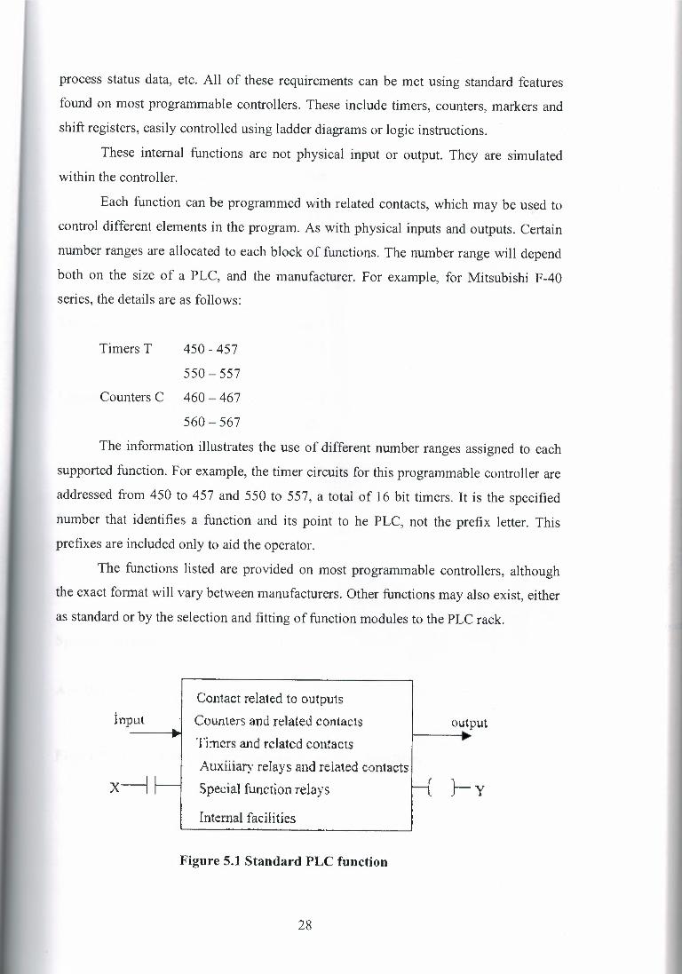
process status data, etc. All of these requirements can be met using standard features
found on most programmable controllers. These include timers, counters, markers and
shift registers, easily controlled using ladder diagrams or logic instructions.
These internal functions are not physical input or output. They are simulated
within the controller.
Each function can be programmed with related contacts, which may be used to
control different elements in the program. As with physical inputs and outputs. Certain
number ranges are allocated to each block of functions. The number range will depend
both on the size of a PLC, and the manufacturer. For example, for Mitsubishi F-40
series, the details are as follows:
Timers T 450 - 457
550- 557
Counters C 460 ~ 467
560- 567
The information illustrates the use of different number ranges assigned to each
supported function. For example, the timer circuits for this programmable controller are
addressed from 450 to 457 and 550 to 557, a total of 16 bit timers. It is the specified
number that identifies a function and its point to he PLC, not the prefix letter. This
prefixes are included only to aid the operator.
The functions listed are provided on most programmable controllers, although
the exact format will vary between manufacturers. Other functions may also exist, either
as standard or by the selection and fitting of function modules to the PLC rack.
Contact related to outputs
Counters and related contacts Timers and related contacts
Auxiliary relays and related contacts Special function relays
Internal facilities
output input
x-J }-y
Figure 5.1 Standard PLC function
28
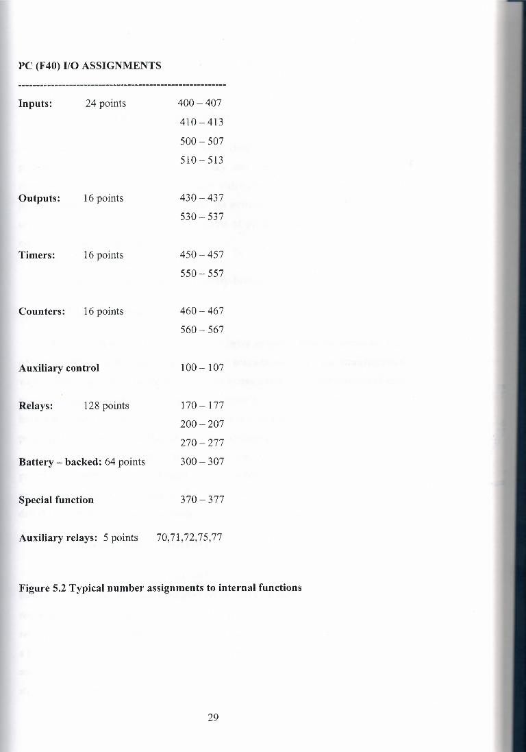
PC (F40) 1/0 ASSIGNMENTS
Inputs: 24 points 400-407
410-413
500- 507
510-513
Outputs: 16 points 430-437
530 - 537
Timers: 16 points 450-457
550- 557
Counters: 16 points 460-467
560- 567
Auxiliary control 100-107
170- 177
200-207
270-277
Battery- backed: 64 points 300 - 307
Relays: 128 points
Special function 370 - 377
Auxiliary relays: 5 points 70,71,72,75,77
Figure 5.2 Typical number assignments to internal functions
29
The operation and use of the listed standard functions is covered in the following
sections.
5.2.2 Markers I auxiliary relays
Often termed control relays or flags, these provide general memory for the
programmer, plus associated contacts. They also form the basis for shift-register
construction. Normally a group of markers with battery back up is provided allowing
process status information to be retained in the event of a power failure. These markers
can be used to ensure safe startup/shut down of process plant by including them as
necessary in the logic sequence.
Referring, the Mitsubishi F40 has:
128 auxiliary (marker) relays, 64 battery-backed markers.
5.2.3 Ghost contacts
In certain cases it will be necessary to derive an output from the combined logic
of several ladder rungs, due to the number of contacts involved. The straightforward
way of providing this is to common-up the respective circuit rungs and drive an internal
relay or marker (M). This acts in the same manner as a 'physical' relay, in that it can
have associated contacts except for the fact that it is simulated by software within the
programmable controller, and has no external appearance whatsoever!
In common with other internal functions, auxiliary relays/markers can be
programmed with as many associated contacts as desired. These contacts may be used
anywhere in a ladder programs as elements in a logic circuit or as control contacts
driving output relays or other functions.
5.2.4 Retentive battery - backed relays
If power is cut or interrupted whilst the programmable controller is operating,
the output relays and all standard marker relays will be turned off. Thus when power is
restored, all contacts associated with output relays and markers will be of possibly
resulting in incorrect sequencing. When control tasks have to restart automatically after
a power failure, the use of battery-backed markers is required. In the above PLC, there
are 64 retentive marker points, which can be programmed as for ordinary markers, only
storing pre-power failure information that, is available once the system is restarted.
30

In figure 8.3 retentive markers M300 is used to retain data in the event of a
power failure. Once input X400 is closed to operate the M300 marker, M300 latches via
it are associated contact.
MJOO~
+ M300
So even if X400 is opened due a power failure, the circuit is holds on restart due
to M300 retaining the operated status and placing its associated contacts in the operated
positions.
Obviously X401 still controls the circuit, and if this input is likely to be
energized (opened) by a power-failure situation, than a further stage of protection may
be used.
5.2.5 Optional functions on auxiliary relays
From the above text it is apparent that auxiliary relays constitute an important
facility in any programmable controller. This is basically due to their ability to control a
large numbers of associated contacts and perform as intermediate switching elements in
many different types of control circuit.
In addition, many PLC manufacturers have provided additional, programmable
functions associated with these auxiliary relays, to further extend their usefulness.
A very common example is a 'pulse' function that allows any designated marker
to produce a fixed-duration pulse at its contacts when operated, rather than the normal
d.c. level change.
This pulse output is irrespective of the duration of relay operation, thus
providing a very useful tool for applications such as program triggering,
setting/resetting of timers and counters etc.
31

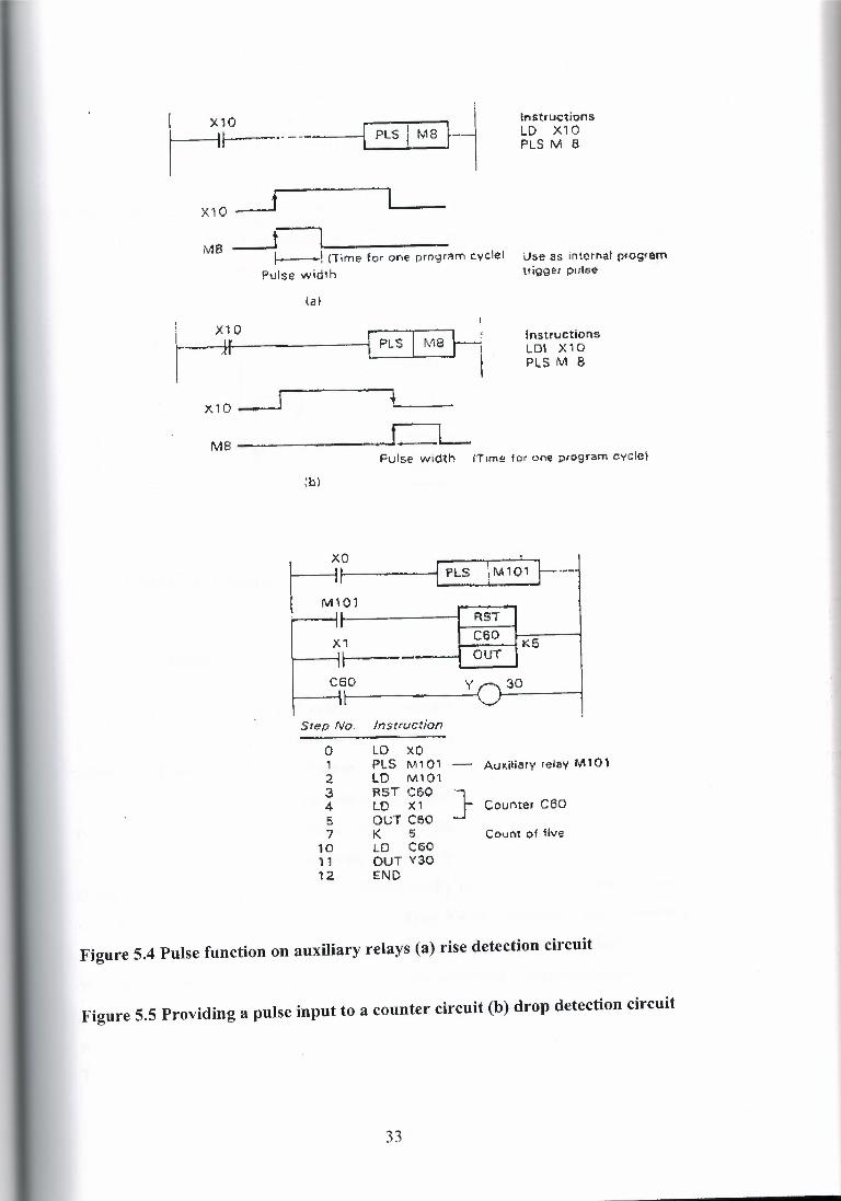
5.2.6 Pulse operation
The programming of these feature varies between controllers, but he general
procedure is the same, and very straightforward.
A pulse-PLS instruction is programmed onto an auxiliary relay number. (in
figure 8.4)
This configures the designated relay to output a fixed-duration pulse when
operated. The examples show how the relay may be used to output a pulse for either a
positive or negative going input.
The circuit in figure 8.5 uses a PLS instruction on auxiliary relay 101 to provide
a reset signal for a counter circuit C60. When input O is operated, a pulse is sent to relay
101, causing its contacts to pulse and reset counter C60. This is used here because
counters and timers often require short duration resetting to allow the restart of the
counting or timing.
32
~~---- ln structi on s LD X10 PLS M 8
X10 ___j
MB _j I• • ! CTimE;- for one prngrl'!n"I ~,,.clel Pulse width
use as int,;irl'lat prog,ern trigger pulse
laf
~; . I Instructions LOI X10 PLS M 8
x,o~~~
MS ,J_L
L_JO . I ., { PLS: 'tM1~1]---~~
t M101 ;.. ---1~-----I
'.b)
Fulse width (Tim~ for one ;;irograrn cvcte]
FtST
--!K5 X1 I H -
C60 y 30
Step No. Instruction
0 LD XO PLS M101 LD M101 RST C:60 }' LD )(1 our C6o K 5 LO C60 OUT Y:30 END
Count of five
Au~i~iary relav M 101 2 3 4 5 7
10 11 12
Coul"lte, C60
Figure 5.4 Pulse function on auxiliary relays (a) rise detection circuit
Figure 5.5 Providing a pulse input to a counter circuit (b) drop detection circuit
33
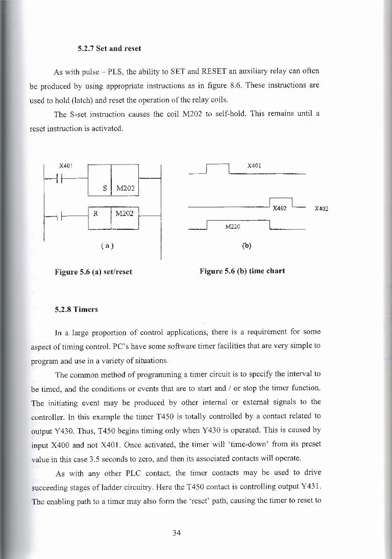
5.2. 7 Set and reset
As with pulse - PLS, the ability to SET and RESET an auxiliary relay can often
be produced by using appropriate instructions as in figure 8.6. These instructions are
used to hold (latch) and reset the operation of the relay coils.
The S-set instruction causes the coil M202 to self-hold. This remains until a
reset instruction is activated.
X 401
I s M202
f ~
I M202 I
(a)
_I X401
X402
_ _j M220
(b)
Figure 5.6 (a) set/reset Figure 5.6 (b) time chart
5.2.8 Timers
In a large proportion of control applications, there is a requirement for some
aspect of timing control. PC's have some software timer facilities that are very simple to
program and use in a variety of situations.
The common method of programming a timer circuit is to specify the interval to
be timed, and the conditions or events that are to start and I or stop the timer function.
The initiating event may be produced by other internal or external signals to the
controller. In this example the timer T450 is totally controlled by a contact related to
output Y 430. Thus, T450 begins timing only when Y 430 is operated. This is caused by
input X400 and not X401. Once activated, the timer will 'time-down' from its preset
value in this case 3.5 seconds to zero, and then its associated contacts will operate.
As with any other PLC contact, the timer contacts may be used to drive
succeeding stages of ladder circuitry. Here the T450 contact is controlling output Y 431.
The enabling path to a timer may also form the 'reset' path, causing the timer to reset to
34

preset value whenever the path is opened. This is the case with most small PC's. The
enabling path 'may contain very involved logic, or only a single contact.
Techniques for programming the preset time value vary little between different
programmable controllers, usually requiring the entry of a constant (K) command
followed by the time interval in seconds and tenths of a seconds. The timers on this
Mitsubishi controller can time from 0.1 - 999 .9 s, and can be cascaded to provide
longer intervals if required.
5.2.9 Counters
Whenever the numbers of process actions or events are significance, they must
be detected and stored in some manner by the controller. Single or small numbers of
events may be remembered by using latched relay circuits, but this is not suitable for
larger event counts. Here programmable counter circuits are desirable, and are available
on all PLC's.
Provided as an internal function, counter circuits are programmed in a similar
manner the timer circuits covered above, but with the addition of a control path to signal
event counts to the counter block. Most PLC counters works as subtraction or 'down'
counters, as the current value is decremented from the programmed set value.
5.2.10 Registers
From using a single internal or external relay as a memory device to store a
single bit of information, other PLC facilities allow the storage of several bits of data at
one time.
The device used to store the data is termed a register, and commonly holds 8 or
16 bits of information. Registers can be through of as individual bit-stores- in fact many
programmable controllers form the data registers out of groups of auxiliary marker
relays in the figure 5.7
Registers are very important for handling data that originates from sources than
simple, single switches. Instead of binary data in one bit wide fort, information in
parallel data form may be read into and out of appropriately sized registers. Thus, data
from devices such as thumbwheel switches, analogue to digital converters, can be feed
35

into appropriate PLC registers and used in later operations that will generate other bit or
byte wide (8-bit) data to drive switched outputs or digital-to-analogue conversion units.
!r\temal -f'':lay-mar/for
D. On/ciH ::: One oit·store 1 to
Pataflel cara register
~rw.y-Ot 8 .bl!..srorss ""register (8-bitl
(<1]
I , t
1-- __ J _) I I
+ [b)
Figure 5.7 Register storage concept (a) array of bit stores; (b) parallel data register
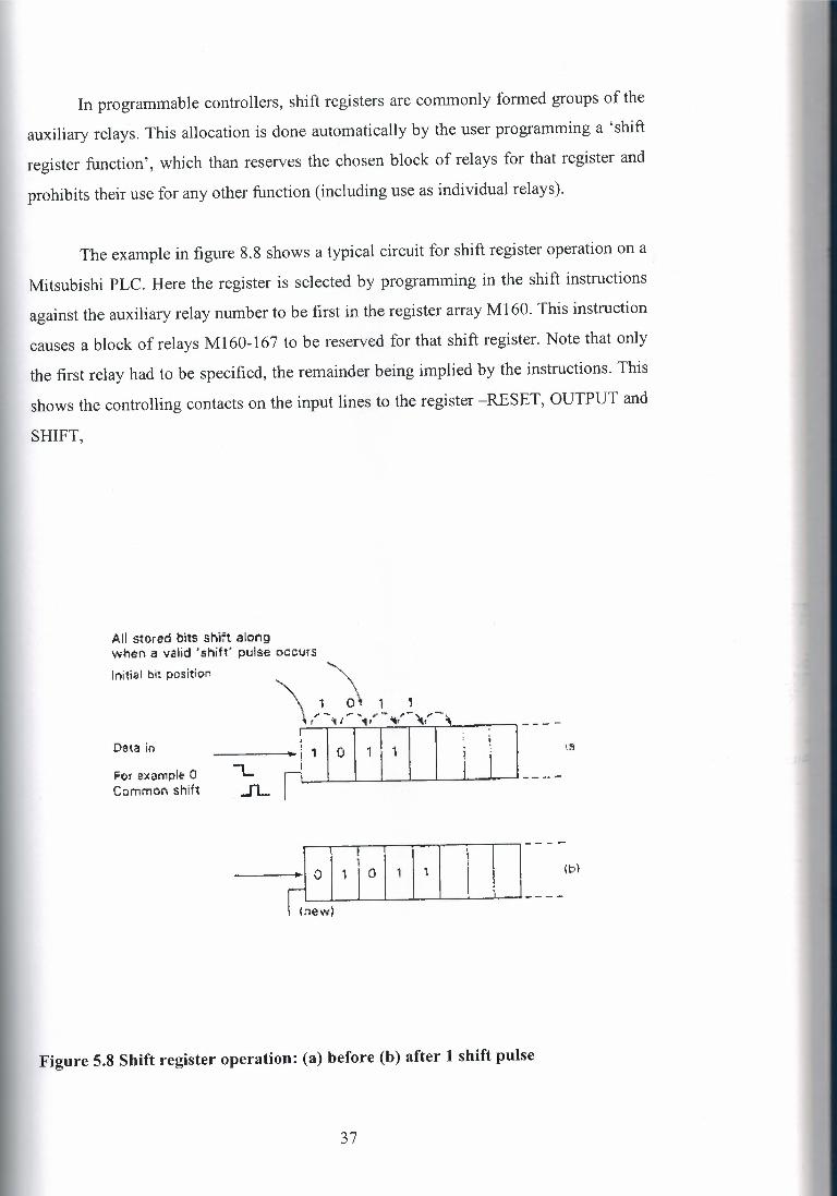
5.2.11 Shift registers
A shift register provides a storage area for a sequence of individual data bits that
are offered in series to its input line. The data are moved through the register under
control of a shift or clock line as in the figure in the 8.8. The effect of a valid shift pulse
is to move all stored digits one bit further in to a register, entering any new data in to the
'freed' initial bit positions. Since a shift register will only be a certain size. For example
8 or 16 bits, then any data in the last bit of the register will be shifted out and lost.
The usefulness of a shift register (SR) lies in the ability to control other circuits
or devices via associated SR contacts that are affected by the stream through the
register. That is, as with marker relays, when a marker is ON any associated contacts
are operated.
36
In programmable controllers, shift registers are commonly formed groups of the
auxiliary relays. This allocation is done automatically by the user programming a 'shift
register function', which than reserves the chosen block of relays for that register and
prohibits their use for any other function (including use as individual relays).
The example in figure 8.8 shows a typical circuit for shift register operation on a
Mitsubishi PLC. Here the register is selected by programming in the shift instructions
against the auxiliary relay number to be first in the register array Ml 60. This instruction
causes a block of relays Ml 60-167 to be reserved for that shift register. Note that only
the first relay had to be specified, the remainder being implied by the instructions. This
shows the controlling contacts on the input lines to the register -RESET, OUTPUT and
SHIFT,
All stored hlts shift along when a valid 'shift' pulse occurs
Initial bit position \
\ }_ ~\ 1
Data in >H.Tll11 I '.1l
Fo1 sxample 0 Ccrnrnon shift
O I 1 I o
c,ew)
Figure 5.8 Shift register operation: (a) before (b) after 1 shift pulse
37

38
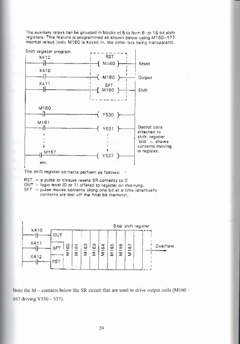
The auxiliarv relays can be grouped in blocks ot 8 to form 8· or 1 6-bit shift registers. This feature is proqrammed as shown below using M160-177 internal relays (only Mt 60 is keyed in. the or her bits being transparent].
Shilt register program r - - - RST-~ -i 1 X41 2 : [ M ~
0~0 1 Reset ! ' ~ j ~ I j
I ( I
X4~1 0 ~ -{ M 1 60 } : . Output
I s=r I~ X411 ! [ M160 ~ Shift ~ I j :
'---------...1 I I I
I M160 --{ Y530 f I
~I ~ l 61 Output coils
.~ 1 Y531 auached .'" "l shift, register
'bits, _ shows
I conte~ts moving
t , in register, I M167 ( Y537
etc.
The shift register contacts perform as fellows:
RST - a pulse or closure resets SR contents to 0 OUT - logic level (0 or l) offered to registe, on this rung. SFT - pulse moves contents ~ior,g one bit at a time (eventvauv
contents are rest oft the final bit rnernorv I.
X410 r-1t- ~:~ Hr
I
8·bi1 shift register --i
OUT
~ol~:NI~ 1 I I
i ~1 t ~ LP (0 r I Overflow
SFT . ~ I ~ I ::" ' ~ (0 <n lO ~ •.... ~ •... ~ ~ ~ ~ ~ ~ ~ :1:
: i RST
Note the M - contacts below the SR circuit that are used to drive output coils (Ml 60 -
167 driving Y530 - 537).
39

It is easier to understand the function of the register if we look at an equivalent
circuit in the figure 8.10. Here we can see the layout of other marker relays following
M160. This helps us to visualize the shifting of data from bit to bit, affecting other parts
of the circuitry as the data (1 or 0) in each bits change.
Shift registers are commonly found as 8 bits or 16 bit, and can usually be
cascaded to create larger shift arrays. This allows data to be shifted out of one register
and in to a second register, instead being lost. Battery-backed markers can be selected
as the register elements if it is necessary to retain register data through a power failure.
5.3 Arithmetic Instructions
5.3.1 BCD numbering
All internal CPU operations are performed in binary numbers. Since it may be
necessary to deal with decimal inputs and outputs in the outside world, conversion using
binary coded decimal (BCD) numbering is provided on most Ply's. BCD numbering is
briefly described in Figure 8.11. Readers wanting further information are referred to the
many texts dealing with number system. When data is already in binary format, such as
analogue values, it is placed directly in registers for use by other instructions.
40

t1} BIN (pure bin.ary)
X7 X6 X5 X4 X3 X2 Xi XO
~.:.-~-To j 0 I i -o Lower (1rgi, ,.
32 16 8 4 2
1 2 8 .• 64 -;, 1 6 .•. 2 •t 1 " ?. 11
Ltpper digit Lt j j
128 64
• In th€ data made up of 8 bits frorr, XO 10 X 7, rhe numcer 211 is expressed when XO. X ~. X-4, X6 ano X7 are turned on r= 1 if' the Jbo'1~ Hgvre! snd the others are t'Jrned o1f I =0 in the e,bove figure I.
(21 BCD !btnary,coded decirnall
M 11 3 Ml 1 2 M 11 1 M 11 0 M 1 0 7 M 1 0 6 M 1 0 5 M 1 0 '- M 10 3 M 1 :)2 M 1 01 M 100
~J" I O I 1 .T O l , I 1 I -~ I ·0 1 i l 1 I ~.~ 800 400 200 100 I 80 40 20 8 4 2
I • --~,...~·--~-~..--,---------· -----·~i-----~----- 1 OOs digit 1 ~ 0:: digit 1 's dig,t
\S00..,. 1 001 + i40 .;. 2C) - 14 - 2 - 1f=967
BCD da13 tS such tr>at each digit of the decirnal -vumbet ;·S exr,HeSSBd in 4-blt bincrv. No di,)lt will e~~e~d 9. E.g.: If both M 103 and M 102 are turned on ("' 1 j in the BCC data shown ·,n :M aoove figure ·,t wHI rest.Mfr, an (!tro·.
Tne values o1 t;rNlrs or ceuotets may tie V";Ca\ed es B.CC
----'TIMER-~ ..,,~, Q C 0
B> 61 {@@'; 40 •• , .&2 4'3
Figure 5.11 (a) Binary and BCD number systems
(b) Timer unit for data operations
41
5.3.2 Magnitude comparison
Magnitude· comparison instructions arc used to compare a digital value read
from some input device or timer, etc., with a second value contained in a destination
data register. Depending on the instruction more than, less than, or equal, this will result
in a further operation when the condition is met. For example, a temperature probe iii a
furnace returns an analog voltage representing the current internal temperature. This is
convened in to a digital value by an analog to digital converter module on the PC, where
it is read from input points by a data transfer instruction and stored in data register DIO.
The process requires that if the temperature is less than 200 C, then the process must
halt due to insufficient temperature.
If the temperature is greater than 200 C and less than 250 C, then the process
operates at normal rate. If the temperature is between 250 and 280 C, than baking time
is to be reduced to 3 minutes 25 seconds, and once temperature exceeds 280 C the
process is to be suspended.
This type of area where magnitude comparison can provide the necessary
control, in conjunction with other circuitry to drive the plant equipment.
Other common applications include the checking of counter and timer values for
action part-way through a counting sequence.
5.3.3 Addition and subtraction instructions
These instructions are used to alter the value of data held in data registers by a
certain amount. This may be used simply to add/subtract an offset to an input value
before it is processed by other instructions. For example, when two different sensors are
passing values to the controller and one sensor signal has to be compared against the
other, but is a fundamentally smaller signal with a narrower output swing. It may be
possible to add an offset to the smaller signal to bring it up near to the level of the larger
one, thus allowing comparison to take place. The alternative would be to use signal
conditioning units to raise the sensor output before the PLC an expensive option.
Other uses of + and - include the alteration of counter and timer presets by
programmed increments when certain conditions occur.
42
CHAPTER6
6. LADDER PROGRAM DEVELOPMENT
6.1 Software Design
When ladder programs are being developed to control simple actions or
equipment, the amount of planning and actual design work for these short programs is
minimal, mainly because there is no requirement to link with other actions or sections
within the program. The ladder networks involved are small enough to be easily
understood in terms of circuit representation and operation. In practice, of course,
circuits are not limited to AND or OR gates, often involving mixed logic functions
together with the many other programmable functions provided by modem
programmable controllers. -
When larger and more complex control operations have to be performed, it
quickly becomes apparent that an informal and unstructured approach to software
design will only result in programs that are difficult to understand, modify, troubleshoot
and document. The originator of such software may posses an understanding of its
operation, but this knowledge is unlikely to remain after even a short period of time
away from that system.
In terms of design methodology, than, ladder programming is no different from
conventional computer programming. Thus, considerable attention must be given to:
• Task definition I specification
• Software design techniques
• Documentation
• Program testing
6.1.1 System functions
Most industrial control systems may be considered as a set of functional areas or
blocks, in order to aid the understanding of how the total system operates.
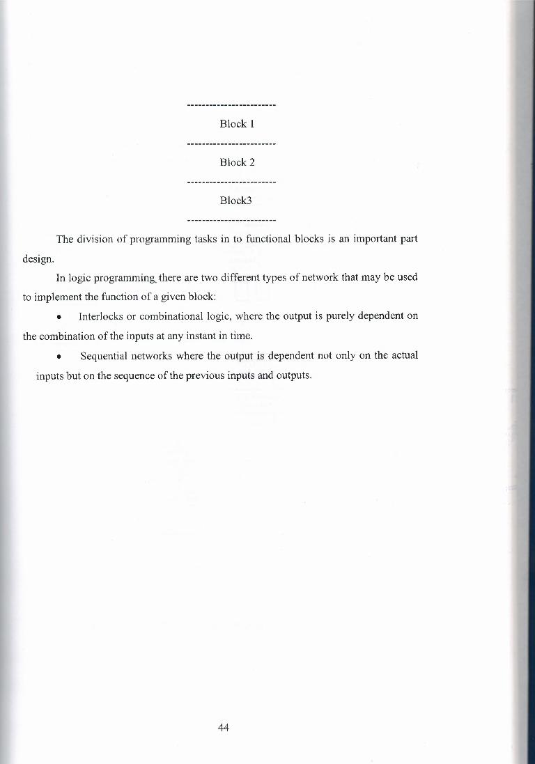
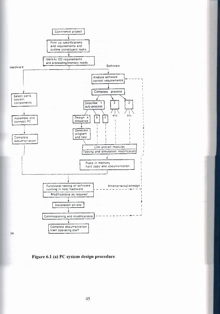
For example, each machine in a plant unit can be treated as a separate sub
process. Each machine process is then broken down in to blocks that may be described
in terms of basic sequences and operations in the figure 9.1 illustrate this approach.
A functional block could for example, consist of all actions required to control a
certain machine in the process.
43
Block 1
Block 2
Block3
The division of programming tasks in to functional blocks is an important part
design.
In logic programming, there are two different types of network that may be used
to implement the function of a given block:
• Interlocks or combinational logic, where the output is purely dependent on
the combination of the inputs at any instant in time.
• Sequential networks where the output is dependent not only on the actual
inputs but on the sequence of the previous inputs and outputs.
44
Commence project
Firm up specifications and requirements and outline constituent tasks
Identify 1/0 requirements and processing/memory needs
Software
Select parts system components
I
' Assemble ;,ind connect PC
Complete documentation
Analyze software control requirements I..._ - - - - "l
I
Design a sequence
etc. ere. I I I .+ I Generate
program and test
Link proven moduies Testing and simulation: moe!iiicanon/ I
5 )
Place in memory hard copy and document anon
(al
I I
Amendmentsiredesign I - - - - - - - - - -- - -I
I I I
+
Functional testing of software running in host hardware
Modifications as required
1 Installation on-site
- - - - - - - - ~- - ...J Commissioning and modifications
Complete documentation train operating staff
Figure 6.1 (a) PC system design procedure
45
General diagram of the complete process - - - --
Description of sub-process 2
- ,-------, : etc. : L..-----.J
Description of sub-process 1
-- I I \ I I \
Object list
Design of sequence 2
Design of sequence 1
- -.. -.. ,...-----, I etc. 1 I I 1----.J
(b)
Figure 9.1 (b) Describing the functional structure of a process
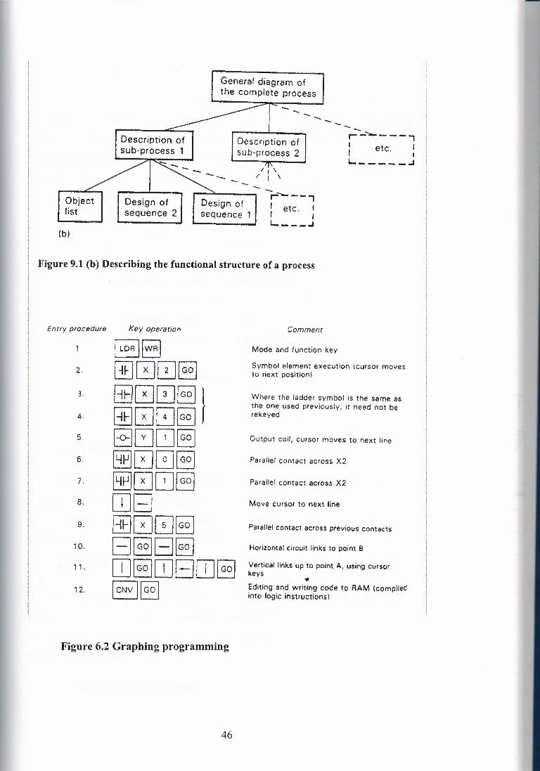
Entry procedure Key operation Comment
~lwRj Mode and function key
2. GIJ00EJ Symbol element execution icursor moves to next position)
3. 8800§]) Where the ladder symbol is the same as the one used previously, it need not be
4. 880GJ~ re keyed
5. ~0~§] Output coil, cursor moves to next line
6. GEJ0GEJ Parallel contact across X2
7. GEJ0~§J Parallel contact across X2
8. [IJEJ Move cursor to next line
9. 8800~ Parallel contact across previous contacts
10. EJE]EJ~ Horizontal circuit links to point B
11 . [IJ ~ [JJ EJ [IJ ~ Vertical links up to point A, using cursor keys •
12. I cNv )!Go I Editing and writing code to RAM (compiled into logic instructions)
Figure 6.2. Graphing programming
46

6.2 Program Structure
At this stage in the investigation of design techniques, it is appropriate to discuss
the layout and structure of PLC programs. It is sound practice to base any program
layout on the general operating structure of all process-control Systems. This means
having definite sections dealing with operating modes, basic functions, process chain or
sequence, signal outputs and status display, as indicated in Table 9.1.
Table 6.1 Sections of a PLC program
Start
Operating modes and basic functions
Starting (basic) position
Enabling I reset conditions
Process operation I sequence logic
Signal outputs
Status I indicator output
Finish
a- Operating modes
Basic position: The controlled equipment is likely to have a basic or normal
position, for example when all actuators are off and all limit switches are open. All
these elements can be combined logically to signify and initialize a basic position,
which may be programmed as a step in a sequential process.
Enabling I reset conditions: Most industrial processes have manual start mid stop
controls that may be incorporated in to the PLC program structure at this point. These
would be included as enabling and reset contacts, having overall control of the PLC in
terms of run or stop. There may also be a manual switch to enable the system outputs,
which would allow the program to run without driving the physical outputs, connected
to the PLC a test function.
b-Process operation/sequence
47
This is the main topic of this chapter, involving the design and programming of
combinational and sequential networks as necessary. The resultant outputs do not
normally drive actuators directly, but instead are used to operate intermediate marker
relays.
c- Signal output
Output signals to process actuators are formed by interlocking the resulting
operation sequence outputs (markers) with any enabling conditions that exist in (a)
above.
d-Status I indicator outputs
Process status is often displayed using indicator lambs or alarms, etc. Such
elements are programmed in this section of the software.
By adopting this systematic approach to program structure, we can create
reliable, easily understood software, which will allow rapid fault location and result in
short process down times. The programs that are developed in this chapter deal mainly
with the topic of process operation, but will be structured in this manner where possible.
9.3 Further Sequential Control Techniques
In many practical applications, a control system has to deal with a process
sequence that requires the concurrent operation and control of more than one step Also,
steps in a sequence may require a time delay or event count as entry criteria for a
succeeding step. To describe the different types of parallel operation, we use the
conventions In figure, actions B OR C are taken, depending on the result of test A2. Either
action will allow entry to action D. In the figure shows the format for a process where
two actions A AND B are initialized once test A is true; also both tests B AND C must
be true before progression to action D.
The equivalent function chart descriptions are illustrated. The number of parallel
activities may be extended via the branching and converging rails. The chart in figure
shows the tests that allow entry to steps B OR C, and also the individual tests or
48

conditions that will allow resetting of the chosen step (test n and run). Notice the OR
signs at each branch rail.
In figure the AND ing of steps is signified by the double connecting rails after
test A and before test n. This means that all parallel steps (in this case B and C) are set
once state A is active and test A is fulfilled.
6.4 Limitation of Ladder Programming
1 - Ladder programs are ideal for combinational/interlock tasks and simple
sequential tasks. However, the lack of comment facilities on most small programmers
makes interpretation of any program extremely difficult.
2 - when applied to complex sequential tasks, ladder programs become cumber
some, difficult both to design and debug. This is mainly due to having to provide entry,
hold and reset elements in every stage to ensure no sequence errors occur.
Several manufacturers are adopting a function block style of programming that
removes most of this complexity. This employs basic programming symbols that are
closely related to the function chart symbols used for program design purposes, as used
earlier in this chapter.
6.4.1 Advanced graphic programming languages
The facility for programming using functional blocks is currently available on a
few larger programmable controllers, such as those from Siemens and Telemechanique.
This approach uses graphic blocks to represent sections of circuitry related to a
particular task or part of a process. Each function block is user programmed to contain a
section of ladder circuitry required to carry out that function. The sequential operation
of the control system is obtained by progression from one block to next, where a step is
entered only if it is entry conditions are fulfilled, in which case it becomes active and
the previous step becomes inactive. Thus, there is no need to reset the previous step an
important advantage over conventional ladder programming.
To examine or program the contents of each block the user would zoom in on
the block in question. These windows in on the contents as shown, which are displayed
49
on the programming panel. The necessary details are then entered in normal ladder
format.
Provision for displaying simultaneous sequences is a further important feature of
these programming methods, displaying the multi tasking ability of PLC's in an easy to
follow manner.
6.4.2 Workstations
The traditional tool for programming PLC's is the small, hand held panel, which can
provide only limited monitoring and editing facilities. Most manufacturers are now
using personal computers as workstations on larger programmable controllers, in order
to fully exploit these features, and those of graphic function blocks.
50

CHAPTER 7
7. CHOOSING INSTALLATION AND COMMISSIONING OF PLC SYSTEM
7 .1 Feasibility Study
Under certain circumstances an initial feasibility study may be suggested or
warranted prior to any decision on what solution will be adopted for a particular task.
The feasibility study may be carried out either by in house experts or by external
consultants. Often an independent specialist is preferred, having few or no ties to
specific vendor equipment. The scope of such a study can vary enormously, from simply stating the
feasibility of the proposal, through to a comprehensive case analysis with complete
equipment recommendations. Typically, though, a feasibility study of this nature
encompasses several specific areas of investigation:
(a) economic feasibility, consisting of the evaluation of possible installation and
development costs weighed against the ultimate income or benefits resulting from
a developed system; (b) technical feasibility, where the target process and equipment are studied in terms
of function, performance and constraints that may relate to achieving an
acceptable system; (c) alternatives, with an investigation and evaluation of alternative approaches to the
development of the acceptable system.
Area (a), economic feasibility and worth, can only be addressed fully once the
result of areas (b) and ( c) are available, with estimated costings, and direct indirect
benefits being considered. Area (b) is detailed in the following sections, with
background information for area (a) usually being compiled through liaison with
company personnel. The achievement of a complete technical proposal requires us to
know what the present and future company needs are in terms of plant automation and
desired information systems. Once the control function has been accurately defined, a suitable programmable
control system has to be chosen from the wide range available. Following the
identification of a suitable PLC, work can begin on aspects of electrical hardware
design and software design.
51

7 .2 Design Procedure for PLC System
Because the programmable controller is based on standard modules, the majority
of hardware and software design and implementation can be carried out independently
of, but concurrently with, each other.
Developing the hardware and software in parallel brings advantages both in
terms of saving time and of maintaining the most flexible an adaptable position
regarding the eventual system function. This allows changes in the actual control
functions through software, until the final version is placed in the system memory and
installed in the PLC.
An extremely important aspect of every design project is the documentation.
Accurate and up-to-date documentation of all phases of a project need to be fully
documented and updated as the job progresses through to completion. This information
will form part of the total system documentation, and can often be invaluable during
later stages of commissioning and troubleshooting.
7 .2.1 Choosing a programmable controller
There is a massi~e range of PLC Systems available today, with new additions or
replacement continually being produced with enhanced features of one type or another.
Manufacturers quickly adopt advances in technology in order to improve the
performance and market status of their products. However, irrespective of make, the
majority of PLC's in each size range are very similar in terms of their control facilities.
Where significant differences are to be found is in the programming methods and
languages, together with differing standards of manufacturer support and backup. This
latter point is often overlooked when choosing a suitable make of controller, but the
value of good, reliable manufacturers assistance cannot be overstated, both for present
and future control needs.
7 .2.2 Size and type of PLC system
This may be decided in conjunction with the choice of manufacturer, on the
basis that more than one make of machine can satisfy a particular application, but with
the vast choice of equipment now available, the customer can usually obtain similar
systems from several original equipment manufacturers (OEM's). Where the
52
specification requires certain types of function or input/output, it can result in one
system from a single manufacturer standing out as far superior or cost-effective than the
competition, but this is rarely the case. Once the stage of deciding actual size of the
PLC system is reached, there are several topics to be considered:
• necessary input/output capacity; types ofl/ 0 required;
• size of memory required;
• speed and power required of the CPU and instruction set.
All this topics are to a large extent interdependent, with the memory size being
directly tied to the amount of I/ 0 as well as program size. As the I/ 0 memory size
rises, this takes longer to process and requires a more powerful, faster central processor
if scan times arc remain acceptable.
7.2.3 I/0 Requirements
The I/ 0 sections of a PLC system must be able to contain sufficient modules to
connect all signal and control lines for the process. These modules must conform to the
basic system specifications as regards voltage levels, loading, etc.,
• The number and type of I/ 0 points required per 'nodule;
• Isolation required between the controller and the target process;
• The need for high speed I/ 0, or remote I/ 0, or any other special facility;
• Future needs of the plant in terms of both expansions potential and installed spare
I/ 0 points,
• Power supply requirements of I/ 0 points are an on board PSU needed to drive any
transducer or actuators? In certain cases there may be a need for signal conditioning modules to be
included in the system, with obvious space demands on the main or remote racks. When
the system is to he installed over a wide area, the use of a remote or decentralized form
of I/ 0 working can give significant economies in cabling the sensors and actuators to
the PLC.
7 .2.4 Memory and programming requirements
Depending on the type of programmable control let being considered, the system
memory may be implemented on the same card as the CPU, or alternatively on
53
. . . . . < )l
dedicated cards. This ladder method is the more adaptable, allowing memory size to be . ,...~}
increased as necessary- up to the system maximum, without a reciprocal change in CPU -~
card. As stated in the previous section, memory size is normally related to the amount
of I/ 0 points required in the system. The other factor that affects the amount of
memory required is of course the control program that is to be installed. The exact size
of any program cannot be defined until of the software has been designed, encoded,
installed and tested. However, it is possible to accurately estimate this size based on
average program complexity A control program with complex, lengthy interlocking or
sequencing routines obviously requires more memory than one for a simple process.
Program size is also related to the number of I/ 0 points, since it must include
instructions for reading from or writing to each point. Special functions are required for
the control task may also require memory space in the unit PLC memory map to allow
data transfer between cards. Finally additional space should be provided to allow for
changes in the program, and for future expansion of the system.
There is often a choice of available memory type RAM or EPROM. The RAM
form is the most common, allowing straightforward and rapid program alterations both
before and after the system is installed. RAM contents are made semi-permanent by the
provision of battery backing on their power supply. RAM must always be used for I/ 0
and data functions, as these involve dynamic data. EPROM memory can be employed for program storage only, and requires the
use of a special EPROM eraser I programmer to alter the stored code. The use of
EPROMS is ideal where identical programmable controllers running the same control
several machines. However, until a program has been a hilly developed and tested, RAM storage
should be used. As mentioned in earlier chapters, microcomputers arc commonly used as
program development stations. The large amounts of RAM and disk storage space
provided in these machines allow the development and storage of many PLC programs,
including related text and documentation. Programs can be transferred between the
microcomputer and the target PLC for testing and alteration. EPROM programming can
also often be carried out via the microcomputer.
54
7 .2.5 Instruction set I CPU
Whatever else is left undefined; any system to be considered must provide an
instruction set that is adequate for the task. Regardless of size, all PLC's can handle
logic control, sequencing, etc. Where differences start to emerge are in the areas of data
handling, special functions and communications. Larger programmable controllers tend
to have more powerful instructions than smaller ones in these areas, but careful scrutiny
of small medium machines can often reveal the capability to perform specific functions
at surprisingly good levels of performance.
In modular programmable controllers there may be a choice of CPU card,
offering different levels of performance in terms of speed and functionality. As the
number of I/ 0 and function cards increases, the demands on the CPU also increase,
since there ate greater numbers of signals to process each cycle. This may require the
use of a faster CPU card if scan time is not to suffer. Following the selection of the precise units that will make up the programmable
controller for a particular application, the software and hardware design functions can
be carried out independently.
7 .3 Installation
The hardware installation consists of building up to necessary racks and
cubicles, then installing and connecting the cabling. The cabinet that contains the programmable controller and associated sub-racks
must be adequate for the intended environment, as regards security safety band
protection from the elements: security in the form of a. robust, lockable cabinet; safety, by providing automatic
cut off facilities alarms if the cabinet door is opened; protection from humid or
corrosive atmospheres by installation of airtight seals on the cubicle. Further
electrostatic shielding by earthing the cubicle body. For maintenance purposes, there must be easy access to the PLC racks for card
inspection, changing etc. Main on/ off and status indicators can be built in to the cabinet
doors, and glass or Perspex windows fined to allow visual checking of card status or
relay/ contactor operation.
55
7.4 Testing and Commissioning
Once the installation work is completed, the next step is to consider the testing
and commissioning of the PLC system. Commissioning comprises two basic stages:
1- Checking the cable connections between the PLC and the plant to be controlled.
2- Installing the completed control software and testing its operation on the target
process- The system interconnections must be thoroughly checked out to ensure all input'
output devices are wired to the correct I/ 0 points. In a conventional control system
buzzing out the connections with suitable continuity test instruments would do this.
With a programmable, however, the programming panel may be used to monitor the
status of inputs points directly this is long before the control software is installed which
will only be done after all hardware testing is satisfactorily completed. Before any
hardware testing is started, a thorough test of all mains voltages, earthing, etc. must be
carried out. With the programmer attached to the PLC, input points are monitored as the
related transducer is operated, checking that the correct signal is received by the PLC.
The same technique is used to test the various function cards installed in the system. For
example, altering can check analog inputs the analog signal and observing a
corresponding change in the data stored in the memory table. In tum, the output devices can be forced by instructions from the programming
panel. Checking their connection and operation. The commissioning team must ensure
that any operation or disoperation of plant actuators will not result in damage to plant or
personnel Testing of some PLC functions at this stage is not always practical, such as for
PID loops and certain communications channel. These require a significant amount of
configuring by software before they can be operated, and are preferably tested once the
control software has been installed. Some programmable controllers contain in built diagnostic routines that can be
used to check out the installed cards, giving error codes on a VDU or integral display
screen. These diagnostic are run by commands from the programming panel, or from
within a control program once the system is fully operational.
56
7.4.1 Software testing and simulation
The preceding sections have outlined the various stages in hardware design and
implementation. Over the same period of time, the software to control the target process
is developed, in parallel, for the chosen PLC system. These program modules should be
tested and proved individually wherever possible, before being linked together to make
up' the complete applications program. It is highly desirable that any faults or error be
removed before the program is installed in the host controller. The time required to rectify faults can be more than doubled .once the software is
running in the host PLC. Virtually all programmable controllers, irrespective of size, contain elementary
software checking facilities. Typically these can scan through an installed program to
check for incorrect labels. Double output coils etc, Listings of all II O points used,
counter/ timer settings and other information is also provided. The resulting information
is available on. the programmer screen or as a printout. However, this form of testing is
only of limited value, since there is no facility to check the operation of the resident
program.
In terms of time and cost economies, an ideal method for testing program
modules is to reproduce the control cycle by simulation; since this activity can be
carried out in the design workshop without having the actually connect up to the
physical process. Simulation of tile process is done in a number of ways, depending on
the size of process involved. When the system is relatively small with only a handful of II O channels it is
often possible to adequately simulate the process by using. Sets of switches connected
up to the PLC as inputs, with outputs represented by connecting arrays of small lambs
or relays in the figure 10.4. This allows inputs to be offered to a test bed controller
containing software under test, checking the action of the control program by noting the
operation and sequence of the output lambs or relays. By operating the input switches in
specific sequences, it is possible to test sequence routines within a program. Where fast
response times are involved, the tester should use the programming panel to force larger
time intervals into the timers concerned, allowing that part of the circuit to be tested by
the manual switch method. Most II O modules have LED indicators that show tile status of the channels.
57
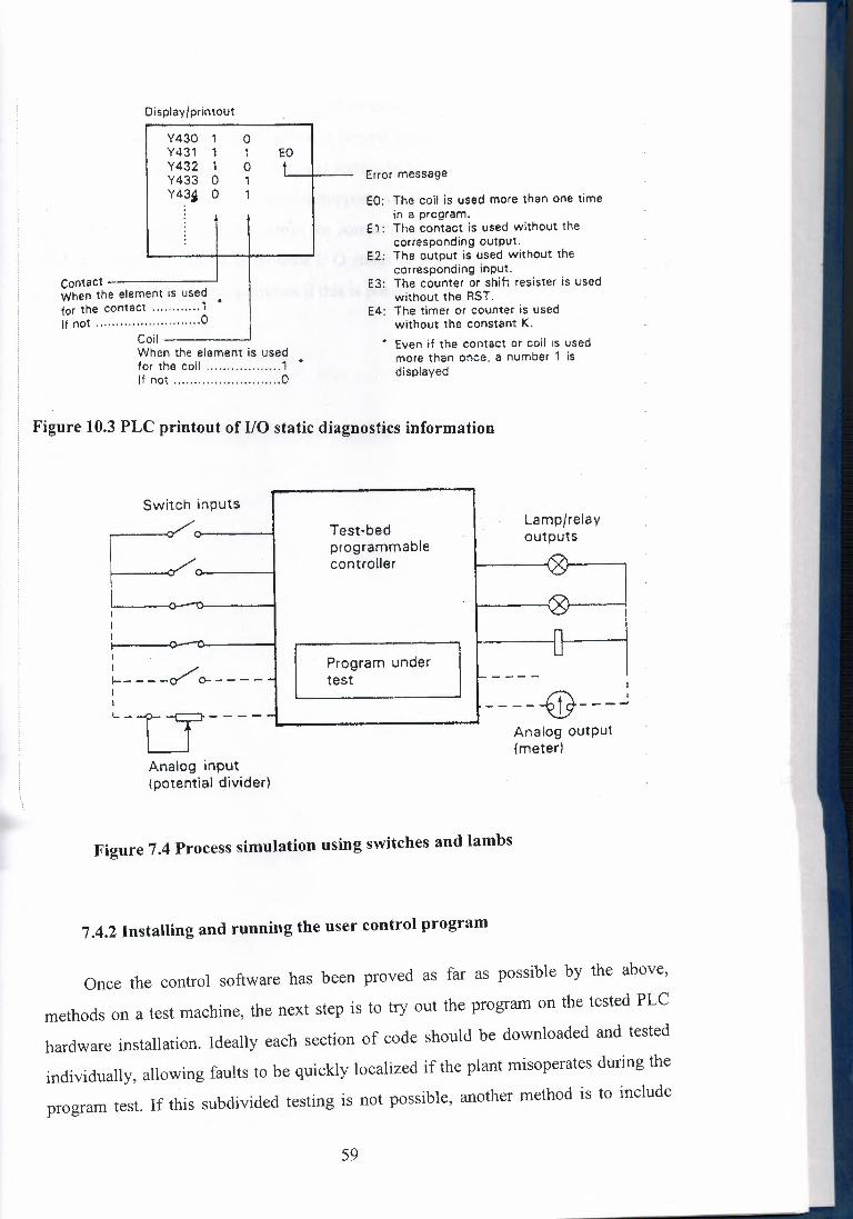
Display/printout
Contact When th tor the c If not ...
Y430 1 0 Y431 1 1 EO Y432 1 0 t Y433 0 1 Y43~ 0 1
is used ......... 1 • ......... 0
Error message
When the element is used for the coil 1 • If not 0
EO: The coil is used more than one time in a program.
E 1 : The contact is used without the corresponding output.
E2: The output is used without the corresponding input.
E3: The counter or shift resister is used without the RST .
E4: The timer or counter is used without the constant K.
• Even if the contact or coil rs used more than once. a number 1 is displayed
Figure 10.3 PLC printout of 1/0 static diagnostics information
Switch inputs
Test-bed programmable controller
Lamp/relay outputs
I
~--- _/ o---- - I
Program under test
____ _J------@---J Analog output (meter)
Analog input {potential divider)
Figure 7.4 Process simulation using switches and lambs
7.4.2 Installing and running the user control program
Once the control software has been proved as far as possible by the above,
methods on a test machine, the next step is to try out the program on the tested PLC
hardware installation. Ideally each section of code should be downloaded and tested
individually, allowing faults to be quickly localized if the plant misoperates during the
program test. If this subdivided testing is not possible, another method is to include
59

JMP commands in the complete program to miss out all instructions except those in
te section to be tested. As each section is proved, the program is amended to place the
JMP instructions so as to select the next section to be tested.
Where a programmable controller supports single step operation, this can be used
ieexamine individual program steps for correct sequencing. Again the programming
mninal should be utilized to monitor I/ 0 status or any other area of interest during
iese tests. With continuous printouts if this is possible.
60
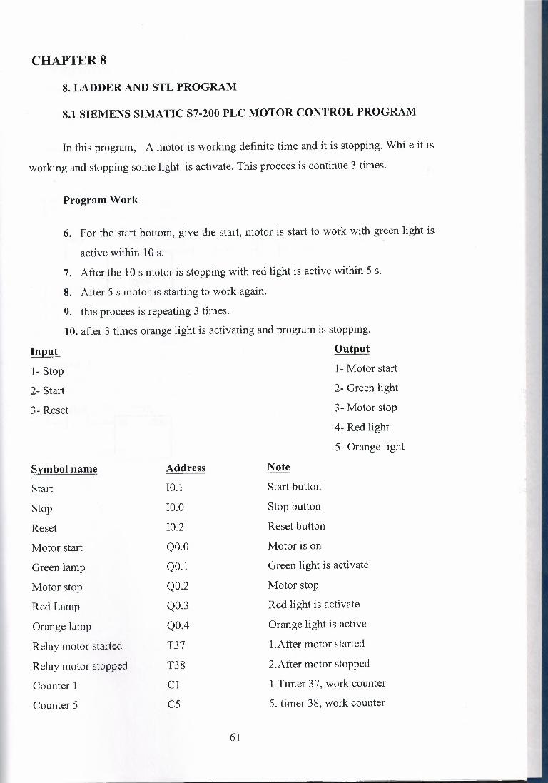
CHAPTERS
8. LADDER AND STL PROGRAM
8.1 SIEMENS SIMA TIC S7-200 PLC MOTOR CONTROL PROGRAM
In this program, A motor is working definite time and it is stopping. While it is
working and stopping some light is activate. This procees is continue 3 times.
Program Work
6. For the start bottom, give the start, motor is start to work with green light is
active within 10 s.
7. After the 10 s motor is stopping with red light is active within 5 s.
8. After 5 s motor is starting to work again.
9. this procees is repeating 3 times.
10. after 3 times orange light is activating and program is stopping.
Input
1- Stop
2- Start
3- Reset
Symbol name Address
Start IO.I
Stop IO.O
Reset I0.2
Motor start QO.O
Green lamp Q0.1
Motor stop Q0.2
Red Lamp Q0.3
Orange lamp Q0.4
Relay motor started T37
Relay motor stopped T38
Counter 1 Cl
Counter 5 cs
61
Output
1- Motor start
2- Green light
3- Motor stop
4- Red light
5- Orange light
Note
Start button
Stop button
Reset button
Motor is on
Green light is activate
Motor stop
Red light is activate
Orange light is active
I .After motor started
2.After motor stopped
1. Timer 3 7, work counter
5. timer 38, work counter

PROGRAM TlTLE COMivtENTS
Press fl for help and example program
Network I NETWORK TITLE (single line)
NETWORK COi'vUVIENTS
Network 2
QO O T37 IN u»:
+ LOO-I PT
62

I Network 3
I I rs 002 HCl, I ;t )
Q03 )
I l Network 4
I I oo.z H i----iIN
I
T38
mNJ l +50-iPT 1
Network 5
I j
I T37, Cl .
~ ~cu c1uT1 I T38 t I ~ ~R I I .
I +HPV
63

I Network 6 I
T38 r I I 10.2 I . t-iR
I +3iPV
I ! N· etwork 'i I _L 'QLYY l.f\. I
I I T37 L.J- I I i 1-. ---!
I I Network 8
I I .. ;,.. r--l.END)
I
I
C5 t----;CU CTI.I
cs I
QO-l L------1, )
64
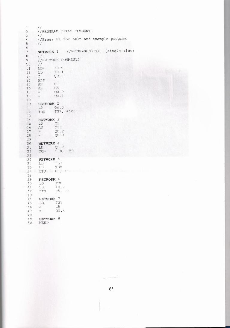
1 / / 2 //PROGRAM TITLE COMMENTS 3 / I 4 I /Press F1 for help and example program 5 //
7 NETWORK 1 //NETl-lORK TITLE (single line} R // (J //NETWORK COMMENTS 10 I I 11 12 13 14 15 1E, 17 J 8 ] '.J 20 NETWORK 21 LD Q . 0 22 TON T 7, +100
LDN IO . Cl LD 10.1 0 QO.O ALD AN Cl AN cs
QO.O OCJ. J
23 24 NETWORK 3 25 LD Cl
T38 Q0.2 Q0.3
26 27
AN
28 29 30 NETWORK 4 31 LD Q0.2 32 33 34 35 3E, -,-, .) I
38
T38, +50 TON
NETWORK 5 LD T37 LD T38 CTU Cl, +1
39 NETWORK 6 40 LD T38 41 LD IO. 2 42 CTU C5, +3 43 44 NETWORK 7 45 LD T37 46 A C5 4 7 = QO. 4 48 49 NETWORK 8 50 MEND
65

Picture 8.1 While motor working with pc and the lamp is active
66
CONCLUSION
When developing this project, I see that PLC makes life easier.
With the information observed from our lecturer, books and examples in the
lecture, I decide that PLC is most useful device for controlling machines. There are too
many advantages using PLC such as controlling several machines, easy to create and
improve or check the program with single PC. In a small time interval we can adjust or
change the operation. We can see the procedure on the PLC without need any device or
computer. The advantages of PLC which is explained before, force us to use the PLC in
the industries or in many areas. Because PLC makes life easier.
67
REFERENCES
(1) Programmable Controllers - Operation and Application
Ian 0. Warnock (1988) Prentice Hall International Ltd.
(2) SIMATIC S7 - 200 and Industrial Automation
Do9. Dr. Salman Kurtulan (July 1998) iTD Electric & Electronic Department
(3) PLC
Richard Bladry (November 1999)
(4) Programmable Logic Controllers
Hugh Jack (June 1999)
(5) Programmable Logic Controllers & Programming
6. Cemal Ozerdem (Nicosia 2001)
68


