
Manual ofStandard Traffic Signs& Pavement Markings
September 2000

Your Comments on this Manual
Any comments on this manual or its contentsmay be directed to:
Traffic & Electrical SectionMinistry of Transportation and Highways
Engineering Branch4B - 940 Blanshard StreetVictoria, B.C. V8W 3E6
This edition replaces the 1998 Interim Edition
Canadian Cataloguing in Publication DataBritish Columbia. Ministry of Transportation and Highways.Engineering Branch.
Manual of standard traffic signs & pavement markings
Previously published: 1997.ISBN 0-7726-4362-8
1. Traffic signs and signals - Standards - British Columbia.2. Road markings - Standards - British Columbia. I Title.
TE228.B74 2000 388.3'122'0218711 C00-960304-2

Continuing Record of Revisions Made to theManual of Standard Traffic Signs
This sheet should be retained permanently in this page sequence within themanual.
All revised material should be inspected as soon as received and the relevantentries made in the spaces provided below.
No. Date Entered by Date of Entry
1
2
3
4
5
6
7
8
9
10
11
12

HOW TO USE THIS MANUAL
The Decimal Indexing System
This manual consists of two parts and numerous chapters andappendices. Each chapter is divided into sections and, wherenecessary, subsections. Sections and subsections are identified by adecimal numbering system; for example, the notation 1.6.2 refers toChapter 1, Section 6, Subsection 2. These numbers should not beconfused with the Sign Numbers which are used to identify individualsigns, for example, when ordering.
As individual pages throughout the manual are not numbered, thelocation of any subject within the text depends on the decimal indexingsystem, and the numerical progression through each chapter.
Revisions and Additions
It may be necessary to add new sections and subsections or to revisesome of the existing ones. By using a decimal indexing system andexcluding page numbers, it will be possible to insert additional materialand still maintain numerical continuity.
Each page has a publication date at the bottom corner. Subsequentupdates will have the new revision date in the same location.
Language:Different words are used throughout the manual to emphasize thedegree to which a policy, warrant or criteria requires adherence too.The following defines the intent of the commonly used word:
SHALL: Describes a mandatory condition - it must be done regardless ofconsequence or price.
SHOULD: Describes an advisory condition - it is desirable to do but notnecessarily mandatory.
MAY: Describes a permissive condition - it is optional to do but in no waynecessary

Abbreviations
The following abbreviations have been used in the text.
Reference Letters for Functional Groups of Signs:
C = Construction and Maintenance G = GuideI = Information P = Parking & StoppingR = Regulatory SP = School & PedestrianTW = Temporary Warning W = Warning
Note: Construction & Maintenance signs (C) and Temporary Warning signs(TW) are detailed in the "Traffic Control Manual for Work on Roadways."
Sign Shapes:
Diam. = Diamond Oct. = Octagon Pent. = PentagonRect. = Rectangle Sq. = Square Trap. = TrapezoidTri. = Triangle
Sign Colours:
B = Black Bl. = Blue Br.= Brown G = GreenOr.= Orange R = Red W = White Y = Yellow
Metric Measurements:
cm = centimetre km = kilometrekm/h = kilometre per hour m = metret = tonne kg = kilogram
Suffixes:
BUS = Buses CHIP = Chip TrucksFARM = Farm Trucks L = LeftLOG = Log Trucks R = RightRV = Recreational Vehicles SP = SpecialT = Tab x = Oversizexx = Oversize xxx = Oversize
The letters L and R identify left and right equivalents of the same sign.The letter T denotes a tab which is generally used only with the sign havingthe same number less suffix.
Miscellaneous:
Bgd. = Background Fl. = Fully Mess. = MessageRefl. = Reflectorized Sy. = Symbol
TABLE OF CONTENTS
1.0 General Provisions
1.1 Introduction
1.2 Authority and Jurisdiction
1.3 Requirements of Signing
1.4 Functional groups of Signs
1.5 Standardization of Application
1.6 Standardization of Design
1.6.1 Shape and Colour1.6.2 Dimensions1.6.3 Message1.6.3.1 Interdictory and mandatory/permissive symbols1.6.4 Retroreflectivity and Illumination1.6.4.1 Means of Reflectorization1.6.4.2 Means of Illumination
1.7 Standardization of Placement
1.7.1 Side of the Roadway1.7.2. Longitudinal Positioning1.7.3 Lateral Positioning1.7.4 Height1.7.5 Angle1.7.6 Mounting and Grouping
1.8 Sign Posts and Bases
1.9 Overhead Signs
1.10 Maintenance
1.11 Sign Supply
2.0 Regulatory Signs
3.0 Warning Signs
4.0 Guide Signs
4.1 Introduction4.2 Control City & Destination Selection Policy4.3 General Conventions for Guide Signs
4.3.1 Colour and Retroreflectivity4.3.2 Lettering

Guide Signs Continued...
4.3.3. Arrows and Borders4.3.4 Abbreviations4.4 Guide Sign Warrants and Application Policy4.5 Freeway Guide Signs4.5.1 Background4.5.2 Conventions for G-5 Signs4.5.3 Guide Sign TheoryFig. 4.1 to 4.xx Sample Guide Sign Applications
5.0 School and Pedestrian Signs
6.0 Information Signs
7.0 Pavement Markings
7.0 Introduction
.1 Materials
.2 Longitudinal Markings.2.1 Colour.2.2 Pattern.2.3 Intersections.2.4 Double Lines.2.5 Single Solid Dividing Lines.2.6 Lane Edge Lines
.3 Transverse Pavement Markings.3.1 Color.3.2 Shapes.3.3 Stop Lines.3.4 Crosswalks.3.5 Lane Use Arrows.3.6 Letters and Symbols
.1 Chevron and Crosswalks Marking in Gore Areas.1.1 Chevron Pavement Markings in Gore Areas.1.2 Crosshatch Pavement Markings in Medians.1.3 Advance Crossing Markings
.2 Raised Pavement Markers (RPM’s).2.1 Guidelines for installations.2.2 RPM – Reflective White Mon-direction.2.3 RPM – Reflective Yellow Mon-directional.2.4 RPM – Reflective Yellow Bi-directional.2.5 RPM – Reflective Red an White Bi-directional.2.6 Reflectors –CMB & CRB
.3 Delineators.3.1 Introductions.3.2 Application.3.3 Specifications.3.4 Delineators on Conventional Highways.3.5 Delineators on Freeway and Expressways
.4 Reserved Lanes
.5 Left Turn Pavement Markings.5.1 Rural.5.2 Urban
.6 Two Way Left Turn Lanes.6.1 General.6.2 Application.6.3 Median Lane Width.6.4 Intersection Treatment
.7 No Passing Zones.7.1 Barrier Lines.7.2 Field Measurement
Appendix
Sign Placement Table I, References, Definitions

CHAPTER 1 GENERAL PROVISIONS
September 2000 1.1Ministry ofTransportationand Highways
1.1 INTRODUCTION
This edition of the British Columbia Manual of Standard Traffic Signs & PavementMarkings replaces the Interim Edition dated May 1989 and is in effect October1, 2000.
This edition now includes the Information Sign Chapter and the Pavement MarkingChapter.
This manual is in general conformance with the Manual of Uniform Traffic ControlDevices for Canada. It also conforms with Motor Vehicle Act Regulations,Division 23, which specifies the designs for a number of the signs contained withinthis manual.
Standardization of design and application aids recognition and understanding ofsigns and is important in obtaining motorist compliance and cooperation.Motorists have a right to expect that any given traffic sign will always have thesame meaning and will require the same response, regardless of where the signis encountered. Similar situations where signs are warranted should, therefore,be signed in a similar manner.
When a traffic sign is correctly used, the majority of motorists will comply with theposted regulation or warning, and drive in a safe and orderly manner. Trafficsigns are most likely to be ignored if insufficient thought and attention has beengiven to their application.
This manual cannot provide solutions for every signing problem. Professionaljudgment will often be required to resolve a situation, but the principles outlined inthis manual must always be followed. Any operational problem addressed bysigning should be regarded as a temporary solution, until a field study proves thesolution is successful. Standardization is important and cannot be over-emphasized. Standard signs must be used wherever practical, and special signsused only when a suitable standard sign will not adequately address the situation.
Chapters 2 to 6 of The Manual of Standard Traffic Signs & Pavement Markingsprovides standards for design and use of traffic signs, but is not intended tooverride good engineering judgment; nor are the recommended standardsintended to be a legal requirement. While the manual contains language such as“shall” there may be circumstances where strict compliance with suchrequirements is not reasonable and it will be necessary to deviate from therequirements.

GENERAL PROVISIONS CHAPTER 1
September 2000 1.2Ministry ofTransportationand Highways
1.2 AUTHORITY AND JURISDICTION
The authority for the placement of traffic signs and other traffic control devices onall streets and highways in British Columbia is contained in various Provincial actsand municipal by-laws.
Some legislation providing authorization for signs may be found in the Ministry ofTransportation and Highways Act Sec 14, and the Motor Vehicle Act Sect 119,135 (2), 146, 208, 209 and 214.
Jurisdiction for traffic control devices is as follows:
• Municipalities: All streets except arterials as defined in Section 27 of theHighway Act.
• Ministry of Transportation and Highways: All arterial highways and public
highways in unorganized areas.
1.3 REQUIREMENTS OF SIGNS Traffic signs are required in order to provide for the safe and orderly movementof motorized and non-motorized traffic and pedestrians. Signs provide informationabout highway routes, directions, destinations and points of interest. They alsoprovide information on regulations which apply to specific locations or at specifictimes, and warn of hazards which may not be evident. To be effective a sign should: • Fulfill a need. • Command attention and respect. • Convey a clear and simple message. • Allow adequate time for a proper response. To meet these objectives, signs must have a carefully considered message, be ofuniform design, and be applied and placed in a consistent manner. Contradictoryor misleading information, incorrect placement or use of inappropriate standardsigns can confuse the road user. It is also most important to recognize thatimproper or excessive use of signs leads to disrespect and non-compliance of thesign.

CHAPTER 1 GENERAL PROVISIONS
September 2000 1.3Ministry ofTransportationand Highways
1.4 FUNCTIONAL GROUPS OF SIGNS The Manual of Uniform Traffic Control Devices for Canada has fiveclassifications of signs as indicated below. For the purpose of this manual, theyhave been divided into the following functional groups: M.U.T.C.D. for Canada M.o.T.H. Regulatory Regulatory Signs: Notify the motorist of
traffic regulations that apply which would not otherwise be apparent. Disregard of thesesigns constitutes a legal offense.
Parking & Stopping Signs: Control parking
and stopping and is a sub-class of the regulatory signs.
Warning Warning Signs: call attention to potentially
hazardous or dangerous conditions on or adjacent to a highway or street.
Information Guide Signs: Display route designations,
destinations, direction and distances to assist motorists in navigating to their destination.
Information Signs: Indicate points of interest
and or display other geographical or cultural information.
School/Pedestrian School & Pedestrian Signs: May be
regulatory or warning and are used to help reduce conflicts between vehicular and pedestrian traffic.
Temporary Conditions Temporary Warning Signs*: Used for
temporary conditions, and are orange They generally have an equivalent with yellow
background in the Warning group. Construction and Maintenance Signs*: Used
during road maintenance or construction. and may be classified as Regulatory or
Warning signs.

GENERAL PROVISIONS CHAPTER 1
September 2000 1.4Ministry ofTransportationand Highways
1.4 Cont’d * Construction & Maintenance (C) signs and temporary warning (TW) signs aredetailed in the Traffic Control Manual for Work on Roadways. Included in the functional groups, there are a number of tabs which may bemounted above or below some primary signs. Tabs are not to be used alone.There are two types of tabs: • A supplementary tab displaying information additional to the message
conveyed by the primary sign. • An educational tab indicates in text form the same message represented by a
symbol on the primary sign. It may be used to convey the meaning of a symbolduring a suitable "educational period," after which it can be removed.
1.5 STANDARDIZATION OF APPLICATION Similar situations must always be signed in the same manner in order to ensurecorrect driver response. Therefore, to maintain signing integrity, standards for theapplication of traffic signs must be upheld. Signs should be used only where they are warranted. Excessive use of signsdetracts from their effectiveness. This manual sets guidelines for the application and use of various types of signs.It is not possible to give specific directions for all situations, and therefore propersigning depends on the experience and good judgment of those responsible fortraffic control. Before a new roadway or detour is opened to traffic, all necessary signs includingdirectional signs and route markers must be in place. Guide signs directing trafficto a detour route should be removed as soon as the detour is removed. Traffic signing should be reviewed frequently to ensure that it is effective, and thatit accurately relates to a road’s present condition. Signs which are no longerrequired must be removed.

CHAPTER 1 GENERAL PROVISIONS
September 2000 1.5Ministry ofTransportationand Highways
1.6 STANDARDIZATION OF DESIGN To simplify the driving task and optimize safety, signs must be recognized andunderstood at a glance. This requires simplicity and uniformity of design, andconsistency of application and placement. Standardization of design includescolour, shape, relative dimensions, message, and illumination or reflectorization. Standardization of design does not preclude further improvement by minorchanges in the proportion of symbols, stroke width and height of letters, width ofborders, or layout of word messages. However all shapes and colours must beas indicated, all symbols must be unmistakably similar to those shown, and alltext must be as specified in this manual. The sign illustrations in this manual are only representations of the true designsand should not be used as patterns for sign manufacture. If a suitable "standard" sign is not available or is inappropriate for a specific trafficcontrol situation, a "special application" sign should be approved by the SeniorTraffic Engineer. Special application signs should conform as closely as possibleto the standards defined in this manual.
1.6.1 SHAPE AND COLOUR The shape and colour of a sign are important as they identify the functional groupto which the sign belongs. Sign colours are indicated under each sign diagram.See “How to Use This Manual” for the abbreviations. Standard sign colours and acceptable tolerances should conform to CanadianGovernment Standards Board (CGSB) Standard 62-GP-11M. The colour of special signs not covered specifically in this manual is governed bythe colour assigned to standard signs of the same functional group.

GENERAL PROVISIONS CHAPTER 1
September 2000 1.6Ministry ofTransportationand Highways
The shape and colour of the different sign groups are as follows: • Construction & Maintenance Signs generally conform to the standards for
regulatory & warning signs except that the warning signs have an orangerather than a yellow background.
• Regulatory Signs are generally vertical rectangles or squares with black
messages on a white background or the reverse. Some signs also incorporatered or green. The major exceptions to this standard are the STOP and YIELDsigns which have unique shapes and colours.
• Parking and Stopping Signs are vertical rectangles with black and red or
green messages on white backgrounds. • Warning Signs are generally diamond shaped with black messages on a
yellow background. • Guide Signs are generally a horizontal rectangle with a white message on a
green background. • Informational Signs are generally horizontal rectangles or squares using
white, combined with green, black and blue. • School and Pedestrian Signs conform to the shape and colour standards of
regulatory and warning signs except for the SCHOOL WARNING sign. • Temporary Warning Signs are generally the same a standard warning signs
except the have an orange background.
In general, tabs are square or horizontal rectangles. Colours are governed by thecolour allotted to the functional group to which they belong.
1.6.1.1 SUBSTRATE
Signs shall be mounted on sheet aluminum, plywood or extruded aluminumsubstrate.
Plywood shall be 16mm Douglas fir, exterior, High Density Overlaid 2 sides,meeting CSA 0121m 1978 .
Sheet aluminum shall be 0.018” (minimum) Alloy 5052-H38 and extrudedaluminum shall be Alloy 6063-T6 conforming to Alcan Shape No. 73247 orequivalent with a yield strength of 255 mpa.
CHAPTER 1 GENERAL PROVISIONS
September 2000 1.7Ministry ofTransportationand Highways
1.6.2 DIMENSIONS
The smallest dimensions shown in this manual are to be regarded as the minimumstandard. An oversize sign is permissible and desirable only where investigationhas shown that a larger sign is needed for satisfactory visual impact and legibility.Care should be taken that no sign in a group or series is disproportionately largeror smaller than the others.
In determining whether an oversize sign is warranted, consideration should begiven to such things as posted speed, background distractions, and degree ofhazard as revealed by accident history or field inspection. There are no simplewarrants for use of oversize signs; each case must be decided on its own merit.It should be recognized that unnecessary use of oversize signs, particularly of theregulatory and warning types will de-emphasize standard size signs and reducetheir effectiveness. An oversize sign must be an enlarged but otherwise identicalversion of the smaller version of the sign.
When referring to dimensions of a sign with unequal sides, the first numberindicates the width and the second number the height. For example a 60 cm x 75cm sign is 60 cm horizontally and 75 cm vertically.
1.6.3 MESSAGE
Sign messages consist of symbols, words, or a combination of both.
Where possible, a symbol should be used in preference to a word message. Newdesigns for symbol signs may require explanatory tabs for an educational period.
Messages for standard signs should be as shown in this manual. If other signmessages are required for special applications, they should be concise and, ifworded, of a letter size which will enable a driver to comprehend the message.
With the rare exceptions shown in the illustrations, all signs have narrow bordersof the same colour as the message.
GENERAL PROVISIONS CHAPTER 1
September 2000 1.8Ministry ofTransportationand Highways
1.6.3.1 UNITS OF MEASURE
Pursuant to the Weights and Measures Act of Canada, all units on standard trafficsigns are to be displayed in metric measure only. The “Thinkmetric” informationsign should be used at all border crossing from the U.S.A. coming into theprovince.
1.6.3.2 LANGUAGE
All signs on provincial highways shall be in English only and text shall becomprised of only the English alphabet. Provincial signs in federal jurisdictionsmust comply with the current Federal language policy.
1.6.3.3 INTERDICTORY AND MANDATORY /PERMISSIVE SYMBOLS
The interdictory symbol is a red ring and diagonal red bar, with the bar normallyoriented from top left to bottom right at a 45 degree angle. Whatever is depictedwithin the interdictory symbol is prohibited.
The mandatory/ permissive symbol is a green ring. Whatever is depicted withinthe green ring is either mandatory or permitted.
1.6.4 REFLECTORIZATION AND ILLUMINATION
Except where noted otherwise, signs in this Manual must be reflectorized and/orilluminated to show the same colour and shape by night as by day. Roadwaylighting may not meet the requirements for sign illumination however it may makethe sign more visible at night if there is some flexibility in placing the sign closer toa luminaire to capture the ambient light.
1.6.4.1 MEANS OF REFLECTORIZATION
Reflectorization is achieved by reflective sheeting on the sign background, on thesign message and border or both.
Reflectorization is provided by enclosed or encapsulated lens retroreflectivesheeting meeting or exceeding CGSB Standard 62-GP-11M. The level ofreflective sheeting required for signs used by the Ministry is shown in the SignCatalogue, available from the MoTH Sign Shop. Prismatic lens sheeting isrestricted in use and may only be used with authorization from the Senior TrafficEngineer.

CHAPTER 1 GENERAL PROVISIONS
September 2000 1.9Ministry ofTransportationand Highways
1.6.4.2 MEANS OF ILLUMINATION
Illuminated signs should be considered wherever reflectorized signs are noteffective; for example, where background light sources or other uncontrollabledistractions reduce visibility of signs and at decision points on high speed/highvolume facilities.
Use of prismatic lens retroreflective sheeting shall not be considered a substitutefor sign illumination, especially in urban areas.
Illumination may be provided by:
• Using light within or behind the sign, which illuminates the main message, thebackground, or both, through a translucent material, or
• An attached or independently mounted sign-lighting fixture directed at the faceof the sign from above or below, or
• Fibre optics or light bulb matrices shaped to the lettering or symbol of a signmessage.
Overhead signs may require lighting since vehicle headlights may not adequatelyilluminate the signs. Shoulder mounted signs generally do not require illuminationunless their position prevents vehicle headlights from adequately illuminating thesign face.
1.7 STANDARDIZATION OF PLACEMENT Standardization of sign placement is desirable although it is not always possible toattain because signs must be accommodated to highway design and the relativepositioning of other signs. The following general criteria on sign placement should be noted: • A sign should be within a driver's field of vision in order to command attention. • A driver traveling at the speed limit must have time to comprehend the sign,
and have adequate time to execute an appropriate response. • Signs should not block sight lines for traffic entering or leaving a roadway. Standard placement may be considered under the following subheadings:

GENERAL PROVISIONS CHAPTER 1
September 2000 1.10Ministry ofTransportationand Highways
1.7.1 SIDE OF ROADWAY The general rule is to locate signs on the right-hand side of the roadway, wheredrivers are accustomed to seeing them. However, in some circumstances, signsmay best be placed on channelizing islands or overhead. In some cases, such aswhen there is poor visibility of a primary sign, it may be desirable to supplement itwith a second sign placed on the left side of the roadway. This is common ondivided roadways and on one-way streets with two or more lanes. Some primary signs may be placed only on the left, such as W-62 CHEVRONALIGNMENT marker, which may be located on the outside of sharp right curves,or the W-54L OBJECT marker, which may be installed in front of obstructions onthe left side of the roadway.
1.7.2 LONGITUDINAL POSITIONING Most regulatory signs are placed where the regulation applies and therefore donot need advance placement. Signs such as guide, informational and warningtypes are placed in advance of the point, object or condition to which they apply.The advance distance at which these signs should be located is generallydependent on the speed limit and should in general conform to Table 1, in theappendix. This table is based on Table II-1 contained in the 1988 edition of theU.S. Department of Transportation Federal Highway Administration Manual ofUniform Traffic Control Devices for Streets and Highways. The advance distancesshown in Table 1 are only a guideline. It is likely that circumstances will exist inwhich sound engineering judgment will support departure from the guidelines. Insuch cases the technical decision maker must document the reasons for deviatingfrom the guidelines. Table 1 does not apply to signs for temporary works or to W-116 PREPARE TO STOP signs. (see W-116 warrant) Placement of C&T-seriessigns is covered by Tables A and B in the Traffic Control Manual for Work onRoadways. Positioning of Regulatory and Warning signs should take precedence over thepositioning of other types of signs. On urban streets, longitudinal positioning may have to be reduced due to limitedblock length, or additional advance warning signs may be required due tointervening public access points. Signs should be positioned so that they are nothidden by parked vehicles.

CHAPTER 1 GENERAL PROVISIONS
September 2000 1.11Ministry ofTransportationand Highways
1.7.2 LONGITUDINAL POSITIONING Cont’d. Where a regulation or warning extends for a considerable distance, signs shouldbe repeated. As a general rule, two signs on separate posts should be erected a minimum of90 m apart (but no closer than 60 m) where the speed limit is 70 km/h or greater,and at least 30 m apart in lower speed areas. Exceptions to this rule should bekept to a minimum as two signs placed close together are difficult to read. To minimize distraction, avoid placing two signs that face in opposite directionsimmediately opposite each other; for example, at a speed zone boundary.
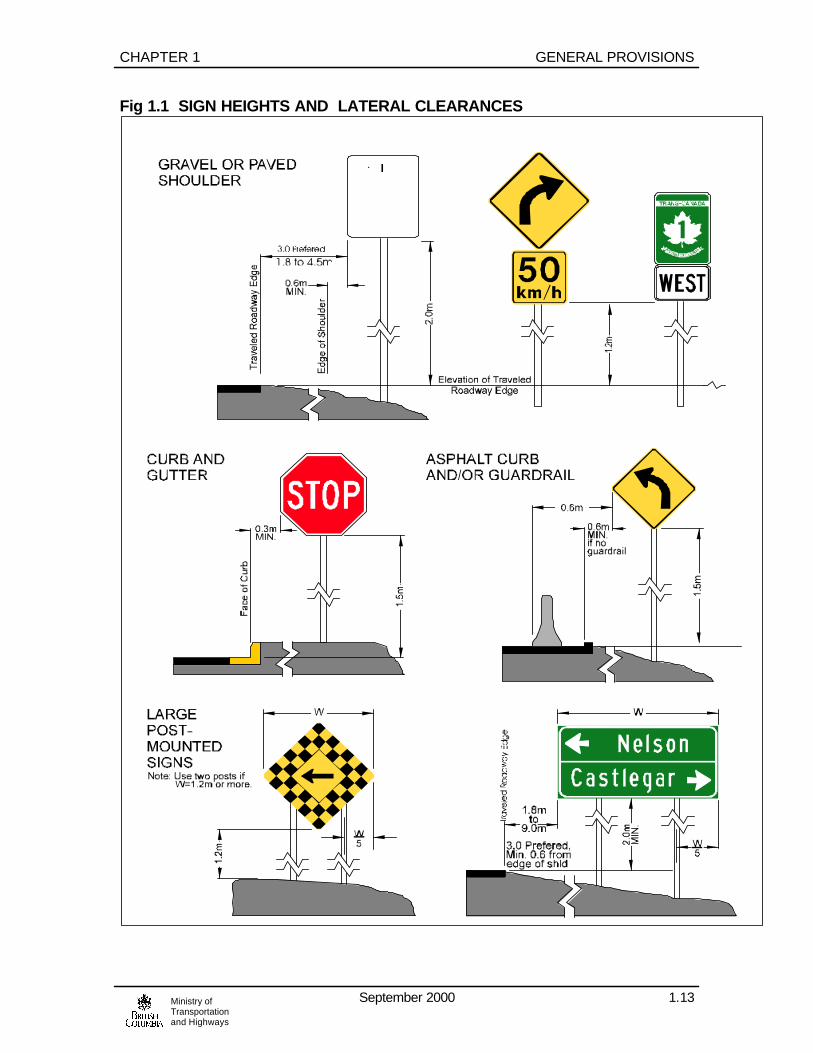
1.7.3 LATERAL POSITIONING On a road with a shoulder, signs are generally placed between 1.8 m and 4.5m,preferably 3 m, from the edge of the traveled roadway. Signs should not beplaced closer than 0.6 m to the face of a roadside barrier or asphalt curb or toany part of the shoulder onto which a vehicle can drive. An exception to theserules is the reduced lateral clearance as indicated in the text for the R-1 STOPsign. Figs 1.1 and 1.2 show examples of typical sign installations. On a road with curb and gutter, a minimum of 0.3 m clearance from the curb faceto the nearest sign edge is permissible. On sections of road where a clear zone has been established, signs supportsmust be outside the clear zone, be of a breakaway design or be protected by abarrier or an attenuator meeting Ministry standards. A sign should not be movedfrom its optimum position in order to meet these requirements.
1.7.4 HEIGHT Shoulder mounted signs: bottom of the sign 1.5 m above the nearest traveledroadway edge. The height may be increased to 2 m under special circumstances,such as an obstruction in the line of sight. Where two or more signs are requiredon the same post, the height to the bottom of the lowest sign may be reduced by0.3 m. For signs mounted on a median, the bottom of the sign should be a minimum 2.0m above the surface of the median. On a freeway or expressway, post mounted directional signs should be mountedwith the bottom of the sign 2 m above the traveled roadway edge.
GENERAL PROVISIONS CHAPTER 1
September 2000 1.12Ministry ofTransportationand Highways
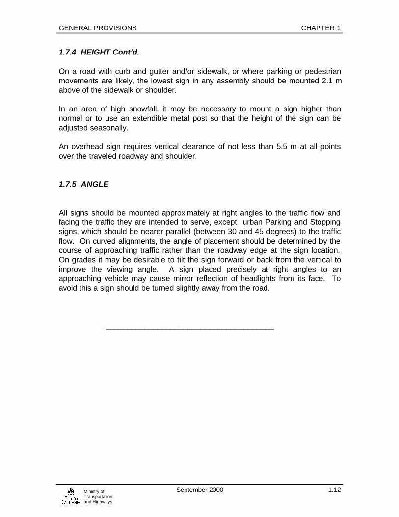
1.7.4 HEIGHT Cont’d. On a road with curb and gutter and/or sidewalk, or where parking or pedestrianmovements are likely, the lowest sign in any assembly should be mounted 2.1 mabove of the sidewalk or shoulder. In an area of high snowfall, it may be necessary to mount a sign higher thannormal or to use an extendible metal post so that the height of the sign can beadjusted seasonally. An overhead sign requires vertical clearance of not less than 5.5 m at all pointsover the traveled roadway and shoulder. 1.7.5 ANGLE
All signs should be mounted approximately at right angles to the traffic flow andfacing the traffic they are intended to serve, except urban Parking and Stoppingsigns, which should be nearer parallel (between 30 and 45 degrees) to the trafficflow. On curved alignments, the angle of placement should be determined by thecourse of approaching traffic rather than the roadway edge at the sign location.On grades it may be desirable to tilt the sign forward or back from the vertical toimprove the viewing angle. A sign placed precisely at right angles to anapproaching vehicle may cause mirror reflection of headlights from its face. Toavoid this a sign should be turned slightly away from the road. _______________________________________
CHAPTER 1 GENERAL PROVISIONS
September 2000 1.13Ministry ofTransportationand Highways
Fig 1.1 SIGN HEIGHTS AND LATERAL CLEARANCES

GENERAL PROVISIONS CHAPTER 1
September 2000 1.14Ministry ofTransportationand Highways
Fig. 1.2 SIGN HEIGHTS AND LATERAL CLEARANCES

CHAPTER 1 GENERAL PROVISIONS
September 2000 1.15Ministry ofTransportationand Highways
1.7.6 MOUNTING AND GROUPING Signs from different functional groups or signs from the same group servingdifferent purposes should not be mounted on the same face of a sign post exceptas follows: • A primary sign supplemented by a tab or tabs• A route marker group• A G-8 sign below a W-6, W-7 or W-12 sign• OBJECT marker below an R-14 sign• A sign or tab which may be mounted together with an R-1 STOP sign as
indicated in the text for that sign. Non-corrosive fasteners are to be used in attaching permanent signs to theirsupports in order to prevent sign discoloration. When two or more signs are used on the same post, the lower sign shall befastened to the post below the upper sign. The two signs shall not overlap.
1.7.7 SEASONAL REMOVAL OF SIGNS
Some sign messages may only be relevant during certain seasons. If a sign isspecified as seasonal, the entire sign face should be removed for the “off” seasonunless the sign is designed as a ‘flip’ style displaying another message or blankgreen face when the message is not desired. Covering the sign with plastic,burlap or other similar materials is not acceptable.
1.8 SIGN POSTS AND BASES Wooden, metal or plastic posts may be used. Plastic posts are generally usedonly for highway delineators. Posts and, where applicable, bases shall be installed to hold signs in positionagainst wind, plowed snow and displacement by vandals. At locations where signsupports could be hit by vehicles, they should be located behind appropriatebarrier or have breakaway footings. A wooden sign post 15 cm x 15 cm (6” x 6”)or larger must have a hole drilled through the post just above ground level, inaccordance with the Standard Specifications for Highway Construction to permit itto break away if hit. Concrete sign bases must be flush with the graded ground level or be locatedbehind roadside barrier. Before excavating for sign supports, confirmation shouldbe obtained that there are no conflicts with underground utilities.

GENERAL PROVISIONS CHAPTER 1
September 2000 1.16Ministry ofTransportationand Highways
1.8 SIGN POSTS AND BASES, Cont’d More than one post will generally be required if a sign is 1.2 m or more in width orhas an area greater than about one square metre. Type, number, and size of signposts can be determined from tables found in the Electrical and TrafficEngineering Manual. For aesthetic reasons, the style and material of sign postson a section of highway should be as consistent as possible. Sometimes a sign can be mounted on a support used for another purpose, suchas a traffic signal or luminaire pole, provided the mounting is done with bandingand no holes are drilled in the poles. Correct location of a sign should not becompromised.
1.9 OVERHEAD SIGNS An overhead sign may be required:
• Where the message is applicable to a particular lane (or lanes), over which thesign is placed.
• In a tunnel, on a bridge or at an other location where there is insufficient room
for a roadside sign. • On a roadway of two or more lanes in one direction where heavy traffic may
interfere with the visibility of a roadside sign. • Where roadside development with brightly lit commercial signs seriously
detract from the effectiveness of a roadside sign. • Where vertical or horizontal curvature limits the visibility of a roadside sign. • For consistency, where other signs on a section of highway are overhead. • On an overhead structure, to indicate a low clearance. • To identify a cross street or a turn control at a signalized intersection. • In high snowfall areas where larger signs such as directional signs may be
obscured by snow. • Where it is deemed necessary to place a warning sign assembly with a large
backboard and/or flashing light overhead for emphasis.

CHAPTER 1 GENERAL PROVISIONS
September 2000 1.17Ministry ofTransportationand Highways
1.10 MAINTENANCE
A clean, legible and properly mounted sign in good condition commands therespect of drivers. A damaged, defaced or dirty sign is ineffective, therefore it isimportant that signs be well-maintained. Dirt which may not be obvious on a signface in daylight can seriously impair the appearance and legibility after dark. Asign, especially one mounted low to the roadway such as an OBJECT marker,may require frequent cleaning.
To ensure proper maintenance, a suitable schedule should be established for theinspection. Cleaning of signs should occur at least twice a year and signs shouldbe replaced immediately when damaged or missing. One inspection per yearshould be carried out at night to ensure adequate brilliance of reflectorizedsurfaces. Police, ministry, and maintenance staff should be encouraged toimmediately report a damaged, obscured or missing sign.
Care should be taken that vegetation does not obstruct the sight line of a trafficsign. Deep snow may require the seasonal raising of sign heights.
For illuminated signs, a regular schedule of lamp replacement should bemaintained so that lamps will be renewed before they are normally expected toburn out.
1.11 SIGN SUPPLY
To ensure uniformity of design, all signs used on Ministry roads for Ministrypurposes must be obtained from:
Provincial Sign Shop945 McMaster Way
Kamloops, B.C. V2V-6K2
Fax: 250 - 828 - 4856
Tel: 250 - 828 – 4851

GENERAL PROVISIONS CHAPTER 1
September 2000 1.18Ministry ofTransportationand Highways
B L A N K

CHAPTER 2 REGULATORY SIGNS
September 2000 2.1Ministry ofTransportationand Highways
R-1 STOP SIGN
R-1T3 3 WAY
R-1T4 4 WAY
R-1 STOP sign is used to control right of way conflicts. The R-1 signindicates to motorists they must completely stop before entering anintersection and may proceed only when it is safe to do so.
R-1 signs should be used only where traffic engineering studies,indicate they are warranted. These studies should consider factorssuch as traffic speeds, traffic volumes, sight distance and collisionexperience.
R-1 signs may be warranted at locations where one or more of thefollowing conditions exist:
• On minor roads which intersect with a major highway or street. • As a general rule, R-1 signs are required on all side roads which
join a main highway at an unsignalized intersection. • At intersections of minor roads where limited sight distance
restricts the safe vehicular approach speed to 15 km/h, or less,and there have been 3 or more accidents per year of a typecorrectable by the R-1 signs.
• Improvements such as parking prohibition and improved sight
distance should implemented first and safety performancemonitored. If this proves ineffective, then consider installing R-1signs.
• At locations where the normal right-of-way rule is ineffective or
creates a hazardous situation and a more positive assignmentof traffic control is required.
• At unsignalized at-grade railway crossings where the sight
distance to an approaching train is inadequate or as an interimmeasure at a crossing scheduled for grade separation orautomatic signal protection.
If an R-1 sign is required on one approach of a four leg intersection,the opposing approach should also be controlled by a R-1 sign. Thisdoes not apply where the main traffic flow is on adjacent

REGULATORY SIGNS CHAPTER 2
September 2000 2.2Ministry ofTransportationand Highways
approaches as in the case where the numbered highway follows aright angle turn through an intersection. The R-1 sign should be used discriminatorily and only whenwarranted. Excessive use of the R-1 sign creates unnecessarydelay to motorists and may contribute to an increase in rear-endcollisions. R-1 signs should not be used as a speed control device,or a primary tool for traffic calming measures. MULTI-WAY STOP CONTROL Multi-way (3-WAY and 4-WAY) stops are a useful means of controlin specific applications. Examples are: • Where traffic signals are not warranted, at the intersection of two
like roadways carrying approximately equal traffic volumes.Entering volumes from all approaches should exceed 500vehicles per hour for any 8 hours of a typical day, and thereshould have been 5 or more right angle or turning accidents peryear of a type correctable by a multi-way stop.
• As an interim measure prior to installation of traffic signals. • As an interim measure prior to undertaking STOP sign reversal. At intersections with three or four stop controlled approaches, theR-1T3 3-WAY, or R-1T4 4-WAY tabs should be used below all theR-1 signs. R-1 SIGN INSTALLATION The R-1 sign should be erected as near as possible to the pointwhere a vehicle is required to stop. The R-1 may be supplementedwith a stop line. Refer to Part B Sec. 2.3.3 for further details on stoplines. The R-1 sign should be placed between 1.8 m and 4.5 m from theedge of the traveled lane of the approach which is stop controlled.(Lane edge line or edge of shoulder) 3.0 m is desirable. On roadswith curb and gutter, the minimum distance between the face ofcurb and left edge of the sign is 0.3 m. See Figure 1.1 for details. The R-1 signs should be placed a minimum of 1.5 m to a maximumof 15 m from the traveled edge of the cross road or intersecting roadway.

CHAPTER 2 REGULATORY SIGNS
September 2000 2.3Ministry ofTransportationand Highways
The R-1 sign should be erected about 1 metre in advance of thestop line or marked crosswalk. The R-1 sign should be oriented so that motorist on the mainlinecannot see the sign face. If this is not practical, the R-1 should beshielded from the mainline motorists by using a visor. Variations of the sign placement dimensions specified above maybe necessary and warranted to optimize the visibility of the R-1 tothe motorist. Engineering judgment should be used to assessspecific sites and variations should be documented. If a STOP sign cannot be seen from a distance in advance of thestop line equivalent to Condition B of Table 1, Appendix A-1, a W-11 STOP AHEAD sign should be erected so that it can be seenfrom that distance. W-11 signs may also be warranted where thestop is unexpected, where speeds are high or for an educationalperiod at newly installed STOP signs. Where two or more lanes of traffic in one direction are controlled bya STOP sign, a second STOP sign should be placed to the left ofthe lanes to which the stop condition applies if a there is a raisedcentre median. The following signs are allowed on the same sign post as the R-1sign: Above the R-1: • G-7 STREET NAME sign• R-3 ONE WAY sign Below the R-1: • R-15 to R19 TURN CONTROL signs• R-136 WAIT HERE FOR FERRY sign• R-1T3 or T4 3-WAY or 4-WAY tab• R-140 YIELD TO ONCOMING TRAFFIC The addition of any of these signs should not obscure the R-1 signin any way and the mounting height of the R-1 sign should not becompromised. STOP signs should not be erected at a signalized intersectionexcept:

REGULATORY SIGNS CHAPTER 2
September 2000 2.4Ministry ofTransportationand Highways
• Where a traffic signal is not functioning due to power failure,breakdown or maintenance.
• At a pedestrian signal where there are no signal indications for
the minor street. OVERSIZE R-1X SIGNS The R-1X oversize STOP sign should be used only in special caseswhere higher sign visibility is required. Oversize sign should berestricted to important highway or street intersections; for example: • At channelized intersections, especially in urban areas, where
a STOP sign must compete with other large traffic signs oradvertising displays.
• At the intersection of two important numbered routes, especially
if such an intersection occurs within a high-speed zone. • At the terminal point of an important numbered route. • On all roads joining or crossing an expressway at grade. R-1x oversize STOP signs should not be used to replace a standardsize STOP sign where the use of a W-11 STOP AHEAD would bemore effective.

CHAPTER 2 REGULATORY SIGNS
September 2000 2.5Ministry ofTransportationand Highways
R-2 YIELD SIGN The R-2 YIELD sign may be used to control right of way conflicts insituations where a stop control is overly restrictive. Motoristapproaching the R-2 sign must yield, and stop if necessary, tomotorist having the right of way. Typical applications for an R-2 mayinclude: • Where traffic enters a major road via a one-way ramp where
available acceleration length is less than specified by currentMinistry design standards. If available acceleration length isequal to or greater than current Ministry geometric standards itis considered a merge condition. See the W-37/W-38 signwarrant.
• On a free right turn lane with little or no acceleration lane. The R-2 sign should not be used: • As a substitute for STOP signs at right angle intersections.
• If it is apparent that a dangerous situation would be created.
• If sight lines for the merging approach are such that the safeapproach speed is greater than 15 km/h.
• To control a major flow of traffic unless that flow is making a right
turn. INSTALLATION CRITERIA: The R-2 sign should be placed on the right side of the road as nearas practical to the point at which a motorist would stop if necessary.In situations where the sign may not be sufficiently conspicuous itmay be supplemented with a secondary sign mounted on the leftside of the road or ramp. The R-2 sign should be placed between 1.8 m and 4.5 m (3.0 mdesirable) from the edge of the traveled lane (lane edge line oredge of shoulder) of the approach which is stop controlled. The R-2 signs should be placed between 5.0m to a maximum of15m from the traveled edge of the cross road or intersecting roadway.

REGULATORY SIGNS CHAPTER 2
September 2000 2.6Ministry ofTransportationand Highways
The R-2 sign should be oriented so that motorists on the mainlinecannot see the sign face. If this is not practical, the R-2 should beshielded from the mainline motorists by using a visor. Variations of the sign placement dimensions specified above maybe necessary and warranted to optimize the visibility of the R-2 tothe motorist. Engineering judgment should be used to assessspecific sites and variations should be documented. The R-2 sign should be visible at a distance based on, Condition B,Table 1, Appendix A-1. If this criteria cannot be met, then a W-13YIELD AHEAD sign should be installed prior to the YIELD sign. AW-13 sign is also used in advance of a YIELD sign in anunexpected location and for an educational period at a newlyinstalled YIELD sign. An R-8 ONE WAY sign may be mounted above and on the sameface of a sign post as a YIELD sign.
____________________________________________

CHAPTER 2 REGULATORY SIGNS
September 2000 2.7Ministry ofTransportationand Highways
MAXIMUM SPEED SIGNS R-3 MAXIMUM XXkm/h AHEAD R-4 MAXIMUM XXkm/h R-5 MAXIMUM XX ENDS R-6 MAXIMUM XXkm/h UNLESS OTHERWISE POSTED The R-3 MAXIMUM SPEED AHEAD sign informs motorists that theyare approaching a lower speed limit. It is always followed by an R-4sign indicating the same speed limit . The R-3 should be installed prior to the R-4 at a distancedetermined from Table 1 Condition C, Appendix. The R-4 MAXIMUM SPEED LIMIT sign establishes a regulatoryspeed zone under Sec. 146 of the M.V.A. The speed limit indicatedon this sign is the maximum lawful speed under ideal conditions forthe segment of highway. The speed zone is always supported by anapproved H223 form. Speed zones must be approved by the Senior Traffic Engineer andare established only after conducting established engineeringstudies. Contact the Office of the Senior. Traffic Engineer for currentspeed zoning policy and warrants. The R-3 and R-4 signs are available in three sizes: • R-3/R-4 60 x 75 cm• R-3X/R-4X 75 x 90 cm• R-3XX/R-4XX 90 x 120 cm The standard R-4 is typically used in urban areas and onconventional highways where the speed limit is under 100km/h. The R-4X should be used on rural conventional highways posted at100km/h or on 4 or more lane highways posted at any speed, andon rural freeways.

REGULATORY SIGNS CHAPTER 2
September 2000 2.8Ministry ofTransportationand Highways
The R-4XX is typically used on freeways for transitioning from highspeed zones to lower speed zones, but may be used as specified bythe Regional Traffic Engineer at other locations if warranted. Maximum speed signs on multi-lane facilities may be erected onthe median 60m ahead of the sign on the right hand side. A Confirmatory R-4 sign should be erected between 300 m and 600m beyond the beginning of a speed zone, and a short distancebeyond each major intersection and beyond the farthest on ramp ofan interchange. On long uninterrupted sections of rural highway, an R-4 sign shouldbe erected, as a minimum of every 15 to 20 km. Speed zones of50 km/h or less in urban areas do not generally require Confirmatorysigns. R-4 signs should not be located immediately in advance of a majorintersection or in advance of a curve, exit ramp, etc. which is signedwith a W-22, W-23 or W-25 ADVISORY SPEED sign. R-4 signs should also be used to confirm the termination of a schoolarea speed zone. The R-4 should be erected 110-150m beyond theSP-1 and tab assembly erected for the opposing traffic flow. STATUTORY SPEED LIMITS: The R-5 MAXIMUM SPEED LIMIT ENDS sign informs the motoristthey are leaving an established speed zone and are entering asegment of highway covered by a statutory speed limit. Any highway not covered by a speed zone approved by the SeniorTraffic Engineer and supported by an H223 form or by a municipalby-law, is covered by a statutory speed limit as described in Sec.146 (1) of the Motor Vehicle Act. The statutory speed limit is 50km/h (incorporated areas) or 80km/h(unincorporated areas). R-4 signs are not installed for statutory speed limits. If a speedzone is established to replace a statutory limit, the appropriateengineering studies, especially curve testing, must be completedbefore regulatory signs are erected.

CHAPTER 2 REGULATORY SIGNS
September 2000 2.9Ministry ofTransportationand Highways
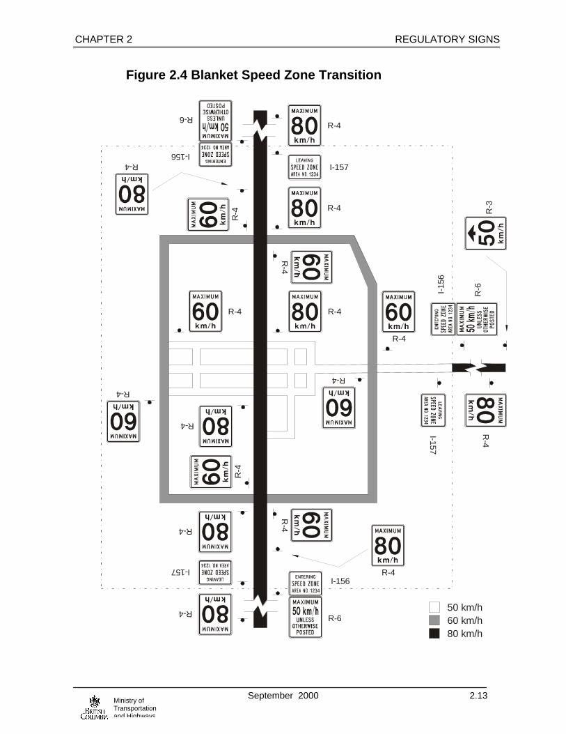
BLANKET SPEED ZONES An R-6 MAXIMUM SPEED UNLESS OTHERWISE POSTED signinforms motorists they are entering an area covered by a blanketspeed zone established under Sec. 146(4) of the Motor Vehicle Act.Blanket zones must not exceed 60km/h. Descriptions of the blanket zones must be published in the BritishColumbia Gazette. The office of the Senior. Traffic Engineer willarrange processing Gazette notices. The I-157E or L sign is mounted above the R-6 sign to identify thebeginning or end of a blanket speed zone. A conventional speed zone may be established on a road coveredby a blanket zone provided the description of the blanket zone endswith “excluding any intervening speed zones.” In this case theconventional speed zone supersedes the blanket zone. Refer to Figures 2.1 to 2.4 for examples of speed zone signing. For other maximum speed limits see sections for SPEED XXkm/h;SP-7 30km/h and SP-8 XXkm/h WHEN CHILDREN ON HIGHWAYtabs.
_______________________________________________

REGULATORY SIGNS CHAPTER 2
September 2000 2.10Ministry ofTransportationand Highways
Figure 2.1 Two-Lane Highway Speed Zone Transition
50 k
m/h
70 k
m/h
tran
sitio
n zo
ne10
0 km
/h
R-4
R-3
300m
-600
mTa
ble
AR-3
NOTE: Speed Zone practice is to limit speed reductions to less than or equal to 30 km/h.
R-4X
R-4
R-4R-4
Tabl
e A

CHAPTER 2 REGULATORY SIGNS
September 2000 2.11Ministry ofTransportationand Highways
Figure 2.2 Freeway Speed Zone Transition
80 k
m/h
110
km/h
R-4X
R-3XXR-4X
R-4X
R-4X
R-4X
R-3XX
300m
-600
m
60m
300m
-600
m
60m
60m
60m
60m
Tabl
e A
R-4X
R-4X
R-4X
R-4X
R-4X

REGULATORY SIGNS CHAPTER 2
September 2000 2.12Ministry ofTransportationand Highways
Figure 2.3 Expressway Speed Zone Transition
80 k
m/h
90 k
m/h
R-4R-4
600m
R-3x
R-3X
R-4X
R-4X
R-4
R-4
R-4x
R-4
R-4X
R-4
60m
TY
P.30
0m to
600
m
300m
to 6
00m
Tabl
e A
R-4X
R-4X
CHAPTER 2 REGULATORY SIGNS
September 2000 2.13Ministry ofTransportationand Highways
Figure 2.4 Blanket Speed Zone Transition
50 km/h60 km/h80 km/h
R-4
R-4
R-4
R-4
R-4
R-4
R-4
R-4
I-157
R-4
R-4
R-4
I-157
R-4
R-4
R-4
R-4
I-157
R-4
R-4
R-6
I-156
R-6
I-156
R-6
R-3
I-15
6

REGULATORY SIGNS CHAPTER 2
September 2000 2.14Ministry ofTransportationand Highways
R-7 SLOWER TRAFFIC KEEP RIGHT The R-7 sign directs motorists to enter the passing or climbing laneif their vehicle is incapable of maintaining a speed that is consistentwith the majority of vehicles on the highway. The R-7 should beinstalled at the taper the climbing or passing lane. A confirmatorysign should be erected approximately 1 km beyond the first andapproximately every 2 km thereafter A confirmatory sign should notbe erected if it would be closer than 1 km to the end of the passingor climbing lane. See Figure 7.37. The R-7 sign may also used on rural multi-lane highways. Wherepossible they should be installed in the median, 100 m to 150 mbeyond the start of the multi-lane section and a short distancebeyond each major intersection and beyond the farthest on-ramp atan interchange. R-7 signs are not used in H.O.V. facilities. R-8 ONE WAY The R-8 sign indicates to motorists that a road is restricted to travelin only one direction. At unsignalized intersections the R-8 sign should be placed in thefar left and near right positions to face motorists approaching theone way road. R-8 signs may be supplemented by a suitable R-15turn control sign placed on the far right. At a signalized intersection the signs should be placed as near aspractical to the appropriate signal heads. At “T” intersections or at commercial access, the R-8 sign should beplaced parallel to the one-way roadway and opposite the access. Asecond R-8, or alternately a suitable R-16 TURN CONTROL signmay be erected in the near right position. If there is a R-1 STOP sign in the near right position an R-8 may bemounted above the R-1 on the same post. The text “ONE WAY” may be added within the arrow to emphasisthe one way message.
CHAPTER 2 REGULATORY SIGNS
September 2000 2.15Ministry ofTransportationand Highways
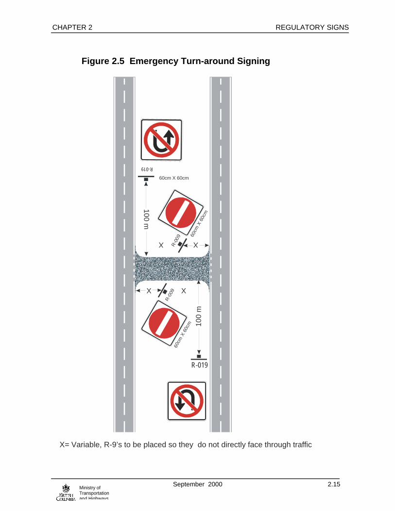
Figure 2.5 Emergency Turn-around Signing
XX
100m
R-0
09
60cm
X60
cm
60cm X 60cm
X X
100
m
R-0
0960
cmX
60cm
R-019
R-019
X= Variable, R-9’s to be placed so they do not directly face through traffic

REGULATORY SIGNS CHAPTER 2
September 2000 2.16Ministry ofTransportationand Highways
R-9 DO NOT ENTER The R-9 sign indicates to motorists that they are not permitted toenter the road or ramp when this sign is visible. The R-9 should beerected in the far right and far left corners of an intersection facingtraffic which might enter a one-way roadway or ramp in the wrongdirection. It may also be erected overhead if this is necessary tomake it more conspicuous. At a signalized intersection where thetraffic on an approach faces a one-way street, the R-9 should beplaced as close to the appropriate signal heads as possible. At a freeway off ramp or other one-way roadway, R-139 WRONGWAY signs should be installed on both sides of the one-wayroadway beyond the R-9 signs. Arrows painted on the pavement on an intersection approach, andindicating the direction of travel on a one-way roadway may also beused to reinforce the ‘do not enter’ message. R-10 TWO-WAY TRAFFIC The R-10 TWO-WAY TRAFFIC signs indicate to motorists that theyare entering a two way road. R-10 signs are required on both sidesof the one-way roadway at the point where the two-way road begins.Confirmatory R-10 signs should be installed approximately 1 km to1.5 km along the two-way roadway and beyond major access points. The R-10 sign may also be used through construction zones if it isnot clear that the road is a two way facility. R-12 ROAD CLOSED The R-12 sign indicates to motorists a road which has beentemporarily closed to all traffic (except to equipment working on theclosed section) for the purposes of construction, maintenance, orbecause of a temporary emergency condition.

CHAPTER 2 REGULATORY SIGNS
September 2000 2.17Ministry ofTransportationand Highways
R-12 T LOCAL TRAFFIC ONLY TAB The R-12 T LOCAL TRAFFIC ONLY tab should be used with the R-12 if access to private property is maintained for local traffic alongthe closed section. Barricades erected at the point of closure shouldhave be placed so local traffic may enter or leave the closedsection safely. The R-12 T tab is installed below the R-12 sign. R-13 VEHICLES INCAPABLE OF 60 km/h PEDESTRIANS, BICYCLES, FARM
IMPLEMENTS, ANIMALS PROHIBITED The R-13 sign should be erected at the beginning or entrances to allSchedule 1 Highways. Where possible it should be so located as toprevent prohibited traffic from entering the highway. Schedule 1Highways are listed in Division 19 of the Motor Vehicle ActRegulations. Where cyclists are allowed on segments of Schedule 1 Highways, amodified R-13 signs with the word “BICYCLES” deleted from thesign may be used. R-14 L KEEP LEFT R-14 R KEEP RIGHT The R-14 R KEEP RIGHT sign is used at the approach end of araised median or traffic island, underpass pier, etc. where traffic isrequired to keep to the right of such obstructions. It should beerected about 6 m beyond the approach end of a median island. Ifrequired on an underpass pier, the KEEP RIGHT sign should bemounted on, or immediately in advance of, the approach face of themedian pier with the inside edge of the R-14 flush with the insideedge of the obstruction. A W-54L OBJECT MARKER should be mounted with a R-14 sign.See the W-54 warrant. The R-14L KEEP LEFT sign is only warranted in special cases,such as paving, sealcoating, or maintenance, where it is necessaryfor traffic to pass an obstruction on the left-hand side.
REGULATORY SIGNS CHAPTER 2
September 2000 2.18Ministry ofTransportationand Highways
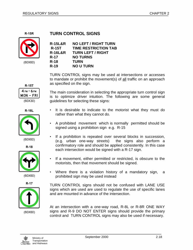
TURN CONTROL SIGNS R-15L&R NO LEFT / RIGHT TURN R-15T TIME RESTRICTION TAB R-16L&R TURN LEFT / RIGHT R-17 NO TURNS R-18 TURN R-19 NO U TURN TURN CONTROL signs may be used at intersections or accessesto mandate or prohibit the movement(s) of all traffic on an approachas specified on the sign. The main consideration in selecting the appropriate turn control signis to optimize driver intuition. The following are some generalguidelines for selecting these signs: • It is desirable to indicate to the motorist what they must do
rather than what they cannot do. • A prohibited movement which is normally permitted should be
signed using a prohibition sign e.g. R-15 • If a prohibition is repeated over several blocks in succession,
(e.g. urban one-way streets) the signs also perform aconfirmatory role and should be applied consistently. In this caseeach intersection would be signed with a R-17 sign.
• If a movement, either permitted or restricted, is obscure to the
motorists, then that movement should be signed. • Where there is a violation history of a mandatory sign, a
prohibited sign may be used instead TURN CONTROL signs should not be confused with LANE USEsigns which are used are used to regulate the use of specific lanesand are mounted in advance of the intersection. At an intersection with a one-way road, R-8L or R-8R ONE WAYsigns and R-9 DO NOT ENTER signs should provide the primarycontrol and TURN CONTROL signs may also be used if necessary.

CHAPTER 2 REGULATORY SIGNS
September 2000 2.19Ministry ofTransportationand Highways
The R-19 NO U TURN sign may be used to restrict motorists frommaking U-turns at intersections or mid-block locations where U-turnsare considered dangerous. R-15T signs are mounted below R-15 to R-19 signs when the turncontrol is not full time. At signalized intersections TURN CONTROL signs should bemounted as near as possible to the applicable signal heads. At unsignalized intersections, TURN CONTROL signs should beplaced on the near right and far left corners of the intersection. If an additional TURN CONTROL sign is erected in advance of anintersection, ensure that there are no alleys or drivewaysintersecting the road between the signs and the main intersection. At any intersection where the turn control is in effect during certainperiods of specified days, or where specific vehicle types areexempted, a tab showing the restricted period or periods and/or theexempt vehicle type should be mounted immediately below eachTURN CONTROL sign. R-22 DO NOT PASS R-23 PASSING PERMITTED The R-22 and R-23 signs may be used where it is necessary toreinforce the passing prohibition imposed by the barrier linemarkings, or where normally permitted passing should be prohibiteddue to construction activity. See the Traffic Control Manual forWork on Roadways. If the passing prohibition is long, intermediateR-22 signs may be required. R-22 sign may also be installed permanently, under exceptionalcircumstances, where collision statistics indicated that it isnecessary to reinforce the passing prohibition imposed by barrierline. An R-23 should always be used in conjunction with an R-22sign to mark the end of the no passing zone (i.e. neither sign shouldbe used without the other).
R-19
(60X60)

REGULATORY SIGNS CHAPTER 2
September 2000 2.20Ministry ofTransportationand Highways
BRIDGE LOAD LIMIT SIGNS R-24 BRIDGE LOAD LIMIT XX TONNES G.V.W. R-24SP MULTI-AXLE VEHICLE BRIDGE LOAD LIMIT Xt G.V.W. SINGLE AXLE Xt, TANDEM AXLE
Xt, TRIDEM AXLE Xt R-24T1 TRUCKS MAXIMUM SPEED XX R-24T2 X km AHEAD Bridge load limits are usually imposed by the Regional BridgeEngineer, but in an emergency, limits may be imposed by anyrepresentative of the Ministry or its maintenance contractors. The R-24SP sign is used to restrict maximum axle loading. It mayindicate any or all of single, tandem and tridem axle restrictions and may also include a G.V.W. restriction. The R-24 sign is used on a structure incapable of carrying themaximum licensed gross vehicle weight. G.V.W. restrictions are shown to the nearest tonne. Axlerestrictions are normally shown to the nearest tonne but never moreprecisely than 0.1 tonne. The R-24T1 TRUCKS MAXIMUM SPEED tab is used with an R-24or an R-24SP sign where a reduction below the prevailing speedlimit is considered necessary because of narrow bridge width or toreduce impact loading on the structure. The R-24 or R-24SP sign combined with appropriate R-24T2 tabshould be erected at the detour or turn-around point to provideadvance notice of the bridge load limit to reduce back tracking. Unless there is an intervening intersection an R-24 or R-25 sign isplaced in advance of the bridge a distance not less than Condition Bof Table 1, Appendix A-1.
CHAPTER 2 REGULATORY SIGNS
September 2000 2.21Ministry ofTransportationand Highways
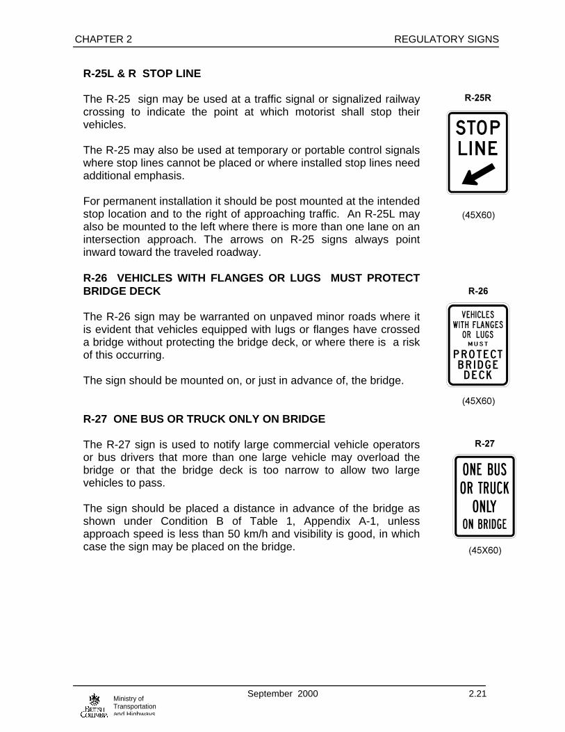
R-25L & R STOP LINE The R-25 sign may be used at a traffic signal or signalized railwaycrossing to indicate the point at which motorist shall stop theirvehicles. The R-25 may also be used at temporary or portable control signalswhere stop lines cannot be placed or where installed stop lines needadditional emphasis. For permanent installation it should be post mounted at the intendedstop location and to the right of approaching traffic. An R-25L mayalso be mounted to the left where there is more than one lane on anintersection approach. The arrows on R-25 signs always pointinward toward the traveled roadway. R-26 VEHICLES WITH FLANGES OR LUGS MUST PROTECTBRIDGE DECK The R-26 sign may be warranted on unpaved minor roads where itis evident that vehicles equipped with lugs or flanges have crosseda bridge without protecting the bridge deck, or where there is a riskof this occurring. The sign should be mounted on, or just in advance of, the bridge. R-27 ONE BUS OR TRUCK ONLY ON BRIDGE The R-27 sign is used to notify large commercial vehicle operatorsor bus drivers that more than one large vehicle may overload thebridge or that the bridge deck is too narrow to allow two largevehicles to pass. The sign should be placed a distance in advance of the bridge asshown under Condition B of Table 1, Appendix A-1, unlessapproach speed is less than 50 km/h and visibility is good, in whichcase the sign may be placed on the bridge.

REGULATORY SIGNS CHAPTER 2
September 2000 2.22Ministry ofTransportationand Highways
VEHICLE WEIGHT RESTRICTIONS R-29 LOAD LIMIT MAXIMUM 70% OF LEGAL AXLE WEIGHT R-30 LOAD LIMIT 3 TONNES G.V.W. The R-29 LOAD LIMIT MAXIMUM 70% OF LEGAL AXLEWEIGHTS imposes vehicle load restrictions for the protection of thehighway during periods when the road sub-base weakens such asduring spring thaw or during frequent freeze/thaw cycles. The R-29 sign may be erected at the discretion of the DistrictHighways Manager after publication in newspapers of notice ofintent to impose temporary load restrictions. The R-29 sign is erected outside urban areas, at main roadjunctions and as necessary to indicate the extent of the loadrestriction. A 50% overlay decal or plate may be used to alter the restrictionpercentage. Typically either a 70% or 50% load restriction would beimposed. The R-30 LOAD LIMIT 3 TONNES G.V.W. sign may be used onunpaved roads when it is necessary to prohibit all traffic except carsand light trucks with a specified maximum gross weight. The R-29 and R-30 signs should be removed as soon as the loadrestrictions are no longer required.

CHAPTER 2 REGULATORY SIGNS
September 2000 2.23Ministry ofTransportationand Highways
R-42 $2000 MAXIMUM PENALTY FOR LITTERING The R-42 sign should be erected near border points for motoristsentering the Province. The R-42 should also be placed on all mainhighways, 50 to 80 kilometers apart for each direction of travel. Inproblem areas, the R-42 sign may be required at more frequentintervals. R-42 T OR DUMPING DOMESTIC WASTE OR SEWAGE The R-42T tab should be installed below the R-42 on the same postand erected at all roadside rest areas maintained by the Ministry.The R-42 and R-42T assemblies should generally be located nearlitter containers and placed so that the message is visible only topeople in the rest area. The R-42T tab should not be visible fromthe highway. R-43 DO NOT DUMP REFUSE This sign may be used to prohibit dumping where evidenceindicates this is taking place in unauthorized areas. R-44 KEEP OFF MEDIAN The R-44 sign may be used on a divided highway where there isevidence of illegal U-turns or driving on unpaved medians. Ifwarranted, it should be erected on the median side of the roadway.

REGULATORY SIGNS CHAPTER 2
September 2000 2.24Ministry ofTransportationand Highways
BRAKE CHECK SIGNS R-45 TRUCKS OVER 5500kg LICENCED GROSS
VEHICLE WEIGHT CHECK BRAKES EXIT XXm R-46 TRUCKS STOP HERE CHECK BRAKES STEEP
HILL AHEAD The R-45 TRUCKS OVER 5500 kg LICENCED GROSS VEHICLEWEIGHT CHECK BRAKES EXIT XXXm sign is used in advance ofa pullout or wide shoulder where a mandatory brake check isrequired for trucks over 5500 kg. G.V.W. The R-45 sign can be supplied with distances other than 600 m butshould not be erected closer to the pullout or wide shoulder than isrequired for Condition B of Table 1, Appendix A-1. The R-45 signis available in three sizes:
• 120cm x 100cm for two lane two-way highways• 240cm x 200cm for 70 km/h>, 4 lane highways• 360cm x 300cm for freeways.
If an R-45 sign is installed requiring truck drivers to check brakes, anR-46 TRUCKS STOP HERE CHECK BRAKES STEEP HILLAHEAD sign is also required within the pullout or area of wideshoulder intended for that purpose. It should be placed on the rightside and downstream near the end of the pullout or wide shoulder. See also W-29 STEEP HILL sign.
Refer to Figures 3.3 and 3.4 for typical sign layouts

CHAPTER 2 REGULATORY SIGNS
September 2000 2.25Ministry ofTransportationand Highways
CHAIN SIGNS R-47 CARRY CHAINS BEYOND THIS POINT R-50 CHAINS MANDATORY ON ALL TIRES OF DRIVE AXLE BEYOND THIS POINT R-52 CHAINS MAY BE REMOVED R-53 VEHICLE COMBINATIONS WITH X OR MORE AXLES OR TOWING TRAILERS MUST CHAIN UP HERE CHAIN SIGNS are installed under authority of the Sec. 208(2) ofthe Motor Vehicle Act and are warranted on any highway whereadverse snow and/or ice conditions may be expected. The R-47 sign is used on roads leading into areas that experiencehigh snowfall, such as mountain passes, to advise motorists chainsmay be required in order to proceed. The R-50 and R-53 may be used interchangeably depending onsite specific conditions. Normally the R-50 is displayed when theuse of tire chains is mandatory, however in some areas onlyvehicles with certain axle configuration experience tractionproblems, therefore the R-53 may be used with the appropriateoverlay displaying the number of axles. Note using an “2” overlayresults in the same message as the R-50. The bottom portion of theR-53 is a hinged sections allowing the message “OR TOWINGTRAILERS” to be covered when this restriction is not required. The R-52 sign should be used at the point where the chain-uprequirement is no longer in effect. See also the G-140 & G-141 CHAIN UP AREA signs.
R-47
120 x 60
R-50
120 x 80
R-52
120 x 60
R-53 O/L
R-53
244 x 122
REGULATORY SIGNS CHAPTER 2
September 2000 2.26Ministry ofTransportationand Highways
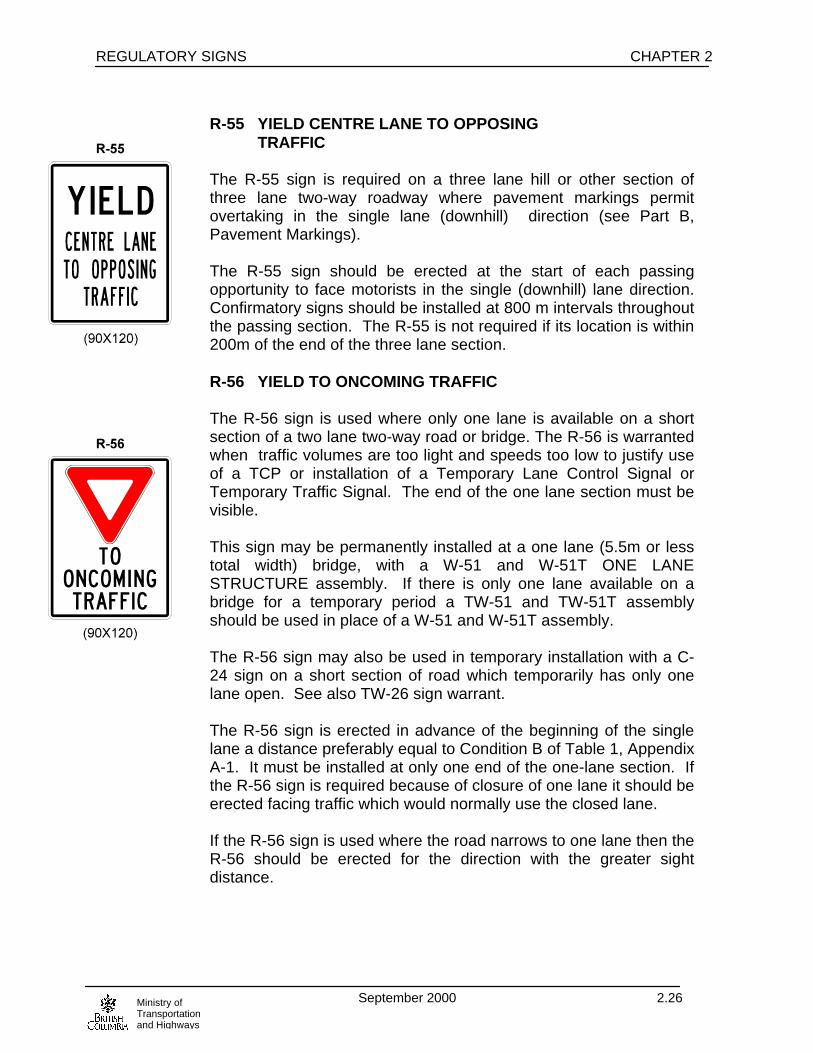
R-55 YIELD CENTRE LANE TO OPPOSING TRAFFIC The R-55 sign is required on a three lane hill or other section ofthree lane two-way roadway where pavement markings permitovertaking in the single lane (downhill) direction (see Part B,Pavement Markings). The R-55 sign should be erected at the start of each passingopportunity to face motorists in the single (downhill) lane direction.Confirmatory signs should be installed at 800 m intervals throughoutthe passing section. The R-55 is not required if its location is within200m of the end of the three lane section. R-56 YIELD TO ONCOMING TRAFFIC The R-56 sign is used where only one lane is available on a shortsection of a two lane two-way road or bridge. The R-56 is warrantedwhen traffic volumes are too light and speeds too low to justify useof a TCP or installation of a Temporary Lane Control Signal orTemporary Traffic Signal. The end of the one lane section must bevisible. This sign may be permanently installed at a one lane (5.5m or lesstotal width) bridge, with a W-51 and W-51T ONE LANESTRUCTURE assembly. If there is only one lane available on abridge for a temporary period a TW-51 and TW-51T assemblyshould be used in place of a W-51 and W-51T assembly. The R-56 sign may also be used in temporary installation with a C-24 sign on a short section of road which temporarily has only onelane open. See also TW-26 sign warrant. The R-56 sign is erected in advance of the beginning of the singlelane a distance preferably equal to Condition B of Table 1, AppendixA-1. It must be installed at only one end of the one-lane section. Ifthe R-56 sign is required because of closure of one lane it should beerected facing traffic which would normally use the closed lane. If the R-56 sign is used where the road narrows to one lane then theR-56 should be erected for the direction with the greater sightdistance.

CHAPTER 2 REGULATORY SIGNS
September 2000 2.27Ministry ofTransportationand Highways
R-57 USE HEADLIGHTS THRU TUNNEL The R-57 sign is required in advance of all major tunnels andsnowsheds. It is placed approximately 50 m in advance of thetunnel portal. The W-30 TUNNEL and W-30T REMOVESUNGLASSES assembly is placed 110 to 230 m in advance of theportal. Signs with the word “TUNNELS” may be used in advance ofmultiple, closely spaced tunnels/snow sheds. R-58 NO TRESPASSING MINISTRY OF
TRANSPORTATION AND HIGHWAYS The R-58 sign is used for the protection of Ministry materials andproperty. It may be erected on any access to Ministry yard, gravelstock pile, etc. at the boundary of the public road right-of-way, or atother locations as required. R-59 DANGER NO TRESPASSING - EXCAVATION The R-59 sign should be installed at locations where the publicmight inadvertently enter Ministry property and be in danger due toan excavation. R-60 NO ENTRY- AUTHORIZED PERSONNEL ONLY- REGULATED UNDER THE MINES ACT-
CONTACT LOCAL DISTRICT HIGHWAYS OFFICE, MINISTRY OF TRANSPORTATION AND HIGHWAYS
The R-60 sign is required at each vehicle entrance to Ministry gravelpits in order to comply with the Mines Act and Code. It is notrequired at temporary borrow sites on Ministry right-of-way, unlessdirected by the Chief Inspector of Mines.
REGULATORY SIGNS CHAPTER 2
September 2000 2.28Ministry ofTransportationand Highways
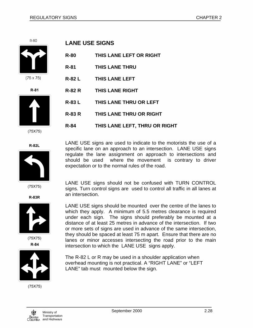
LANE USE SIGNS R-80 THIS LANE LEFT OR RIGHT R-81 THIS LANE THRU R-82 L THIS LANE LEFT R-82 R THIS LANE RIGHT R-83 L THIS LANE THRU OR LEFT R-83 R THIS LANE THRU OR RIGHT R-84 THIS LANE LEFT, THRU OR RIGHT LANE USE signs are used to indicate to the motorists the use of aspecific lane on an approach to an intersection. LANE USE signsregulate the lane assignment on approach to intersections andshould be used where the movement is contrary to driverexpectation or to the normal rules of the road. LANE USE signs should not be confused with TURN CONTROLsigns. Turn control signs are used to control all traffic in all lanes atan intersection. LANE USE signs should be mounted over the centre of the lanes towhich they apply. A minimum of 5.5 metres clearance is requiredunder each sign. The signs should preferably be mounted at adistance of at least 25 metres in advance of the intersection. If twoor more sets of signs are used in advance of the same intersection,they should be spaced at least 75 m apart. Ensure that there are nolanes or minor accesses intersecting the road prior to the mainintersection to which the LANE USE signs apply. The R-82 L or R may be used in a shoulder application whenoverhead mounting is not practical. A “RIGHT LANE” or “LEFTLANE” tab must mounted below the sign.

CHAPTER 2 REGULATORY SIGNS
September 2000 2.29Ministry ofTransportationand Highways
SIDE MOUNTED LANE USE SIGNS R-85L TWO LANES LEFT R-85R TWO LANES RIGHT R-86L LEFT LANE LEFT, RIGHT LANE THRU R-86R LEFT LANE THRU, RIGHT LANE RIGHT R-87L LEFT LANE LEFT, RIGHT LANE LEFT OR THRU R-87R LEFT LANE THRU OR RIGHT, RIGHT LANE RIGHT See the first paragraph of OVERHEAD LANE USE SIGNS forwarrants for SIDE MOUNTED LANE USE SIGNS. Overhead LANE USE SIGNS are preferable to side mountedones. However, side mounted signs may be used as atemporary installation until overhead signs can be installedThey may be used as a permanent installation provided trafficspeed and volume are low and the lane the sign applies to isno more than two lanes away from the sign.

REGULATORY SIGNS CHAPTER 2
September 2000 2.30Ministry ofTransportationand Highways
TWO-WAY LEFT TURN LANE SIGNS R-88 TWO-WAY LEFT TURN LANE BEGINS R-89 TWO-WAY LEFT TURN LANE ENDS R-90 TWO-WAY LEFT TURN LANE R-88 and R-89 signs are usually placed back to back, to indicatethe commencement or termination of a two way left turn lane.Where there is a raised median island they may be post mountedon the island. If there is no raised island, oversize signs should bemounted over the middle of the lane. The R-90 sign is installed, usually back to back, over the middle of atwo-way left turn lane approximately 200 m from R-88 and R-89signs and from other R-90 signs, with at least one pair per block. Refer to Figure 2.6 for typical two way left turn signing.

CHAPTER 2 REGULATORY SIGNS
September 2000 2.31Ministry ofTransportationand Highways
Figure 2.6 Two Way Left Turn Lane Signing
XYZRD.
XYZ RD.
XYZ RD.
XYZRD.
R-1
R-1 G-7
G-7 (MOUNTEDON SIGNAL ARM)
G-7 (MOUNTEDON SIGNAL ARM)
G-7
MINOR CROSS STREET(UNSIGNALIZED)
MAJOR CROSS STREET(SIGNALIZED)
R-90
R-90
USE R-90 MIDWAY BETWEENR-88 AND R-89 WHEN THEDISTANCE IS < 400 m OREVERY 200 m
R-88
R-89
DRIVEWAY
DRIVEWAY
DRIVEWAY
REGULATORY SIGNS CHAPTER 2
September 2000 2.32Ministry ofTransportationand Highways
B L A N K

CHAPTER 2 REGULATORY SIGNS
September 2000 2.33Ministry ofTransportationand Highways
R-100 AIRCRAFT PATROLLED The R-100 sign should be installed for a six month introductoryperiod at the first pavement marking of a newly established aerialspeed check zone. R-101 END OF PUBLIC ROAD The R-101 sign is used to mark the end of a public road and thestart of a private road on which public traffic is allowed. R-102 END OF MAINTAINED PUBLIC ROAD The R-102 sign is used to mark the point on a public road beyondwhich maintenance is not carried out regardless of whether the roadbeyond is public or private. R-103 EXCEPT BUSES The R-103 sign may be used immediately below R-9 DO NOTENTER or TURN CONTROL SIGNS where buses are exemptedfrom restrictions which apply to other traffic. If used in conjunctionwith a TURN CONTROL SIGN and an R-15T TIME RESTRICTIONtab, the R-103 sign should be mounted below the R-15T tab.

REGULATORY SIGNS CHAPTER 2
September 2000 2.34Ministry ofTransportationand Highways
R-104 VEHICLES OVER 5,500 KG LICENCED GROSS
R-104TBUS INCLUDING BUSES NOT LICENSED IN B.C.
R-104TCHIP EMPTY CHIP TRUCKS EXEMPT
R-104TFARM EMPTY FARM TRUCKS EXEMPT
R-104TLOG EMPTY LOG TRUCKS EXEMPT
R-104TRV RECREATIONAL VEHICLES EXEMPT ALL TABS The R-104 sign is required in advance of any permanent scale todirect commercial vehicle operators to provincial weight scales. The R-104 may be supplied in two formats: 1. In two pieces which permits the bottom half to be folded upobscuring the message when the scale is closed. 2. In one piece but used in conjunction with a changeable messagesign reading “SCALE OPEN/CLOSED”. The R-104 and changeable message OPEN/CLOSED sign, if used,should be placed at distances in advance of the beginning of thescale exit taper/ access or in advance of the widest point of themedian left turn island in the case of left accesses, as follows:
a) Two Lane Conventional Highways: • R-104: 300 m • If an changeable message OPEN/CLOSED sign is used,
it will be placed 300 m and the R-104 at 600 m. b) Four Lane Highways: • G-130 “SCALE 300m” at 300 m; R-104 at 600 m • If a changeable message OPEN/CLOSED sign is used it
should be placed at 300m, the G-130 at 600 m and theR-104 at 900 m
R-105
300 x 180
R-104
(240 x 200)

CHAPTER 2 REGULATORY SIGNS
September 2000 2.35Ministry ofTransportationand Highways
c) Scales accessed via an interchanges: R-104 sign should be located mid way between the 1200 m and 600 m advance directional signs. If an changeable message OPEN/CLOSED sign is used it should be located mid way between the 600 m advance direction sign and the turnoff directional sign at the start of the off ramp taper. All directional signs for the approach should include the message SCALE in green on white as the bottom line.
Under conditions (a) and (b) for a scale on the right with an exittaper a G-131 sign should be placed at the beginning of the taper. Ifthere is no taper a G-132R should be used immediately in advanceof the access. For a scale on the left a G-132L sign should beplaced on the right side adjacent to the widest point of the medianleft turn island. Tab signs as illustrated may be added below an R-104 sign at thediscretion of the scale operator. Oversize R-104 signs and tabs should be used where there are twoor more lanes in one direction and the speed limit is 70km/h orhigher. R-106 DO NOT BLOCK INTERSECTION R-107 DO NOT BLOCK ACCESS The R-106/R-107 signs may be used where queuing vehicles createa problem by blocking access at minor intersections or majorcommercial accesses.
REGULATORY SIGNS CHAPTER 2
September 2000 2.36Ministry ofTransportationand Highways
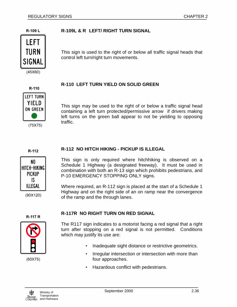
R-109L & R LEFT/ RIGHT TURN SIGNAL This sign is used to the right of or below all traffic signal heads thatcontrol left turn/right turn movements. R-110 LEFT TURN YIELD ON SOLID GREEN This sign may be used to the right of or below a traffic signal headcontaining a left turn protected/permissive arrow if drivers makingleft turns on the green ball appear to not be yielding to opposingtraffic. R-112 NO HITCH HIKING - PICKUP IS ILLEGAL This sign is only required where hitchhiking is observed on aSchedule 1 Highway (a designated freeway). It must be used incombination with both an R-13 sign which prohibits pedestrians, andP-10 EMERGENCY STOPPING ONLY signs. Where required, an R-112 sign is placed at the start of a Schedule 1Highway and on the right side of an on ramp near the convergenceof the ramp and the through lanes. R-117R NO RIGHT TURN ON RED SIGNAL The R117 sign indicates to a motorist facing a red signal that a rightturn after stopping on a red signal is not permitted. Conditionswhich may justify its use are:
• Inadequate sight distance or restrictive geometrics.
• Irregular intersection or intersection with more thanfour approaches.
• Hazardous conflict with pedestrians.
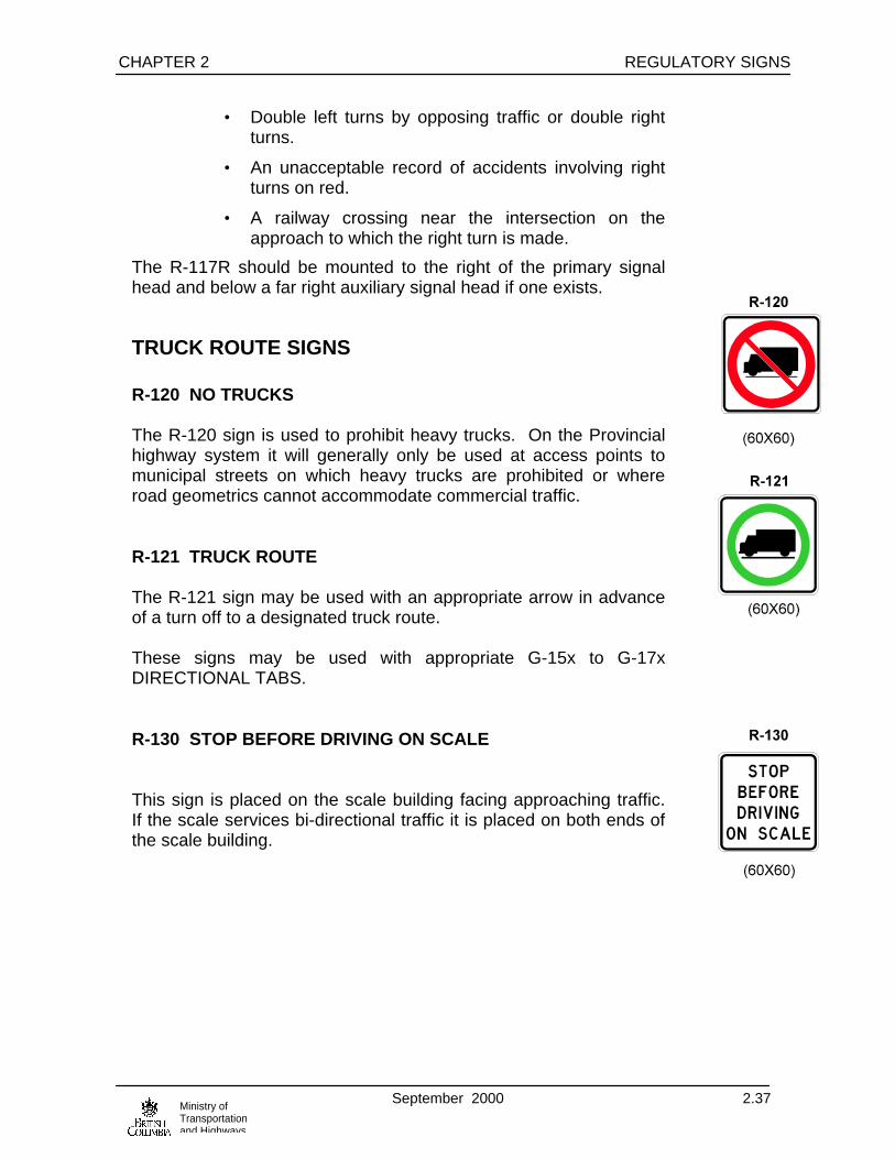
CHAPTER 2 REGULATORY SIGNS
September 2000 2.37Ministry ofTransportationand Highways
• Double left turns by opposing traffic or double rightturns.
• An unacceptable record of accidents involving rightturns on red.
• A railway crossing near the intersection on theapproach to which the right turn is made.
The R-117R should be mounted to the right of the primary signalhead and below a far right auxiliary signal head if one exists.
TRUCK ROUTE SIGNS
R-120 NO TRUCKS
The R-120 sign is used to prohibit heavy trucks. On the Provincialhighway system it will generally only be used at access points tomunicipal streets on which heavy trucks are prohibited or whereroad geometrics cannot accommodate commercial traffic.
R-121 TRUCK ROUTE
The R-121 sign may be used with an appropriate arrow in advanceof a turn off to a designated truck route.
These signs may be used with appropriate G-15x to G-17xDIRECTIONAL TABS.
R-130 STOP BEFORE DRIVING ON SCALE
This sign is placed on the scale building facing approaching traffic.If the scale services bi-directional traffic it is placed on both ends ofthe scale building.

REGULATORY SIGNS CHAPTER 2
September 2000 2.38Ministry ofTransportationand Highways
R-136 WAIT HERE FOR FERRY
At a minor ferry terminal the R-136 sign may be installed below anR-1 STOP sign to mark the point from which vehicles waiting for aferry should queue.
R-139 WRONG WAY
The R-139 sign should be used as a supplement to R-9 DO NOTENTER signs where motorists frequently proceed the wrong way ona freeway off ramp or other one-way roadway. It should be installedon both sides of the one-way roadway below the R-9 signs.
R-140 YIELD TO ONCOMING TRAFFIC
The R-140 sign should be used at an intersection where there isonly one stop controlled approach and traffic on the otherapproaches are unregulated.
The R-140 is placed below the STOP sign.
An R-140 sign must not be substituted for an R-56 if the R-56 iswarranted.
R-152 NO BICYCLES
The R-152 sign may be used at the point where bicycles arerequired to leave a main roadway and follow another road, aseparate bike path or to traverse an interchange by following theramps rather than the through roadway.
R-153 CYCLISTS STOP AND DISMOUNT
The R-153 sign may be used where it is felt necessary to havecyclists dismount and walk their bicycles for their own safety or thatof pedestrians.
R-140
(60 x 30)

CHAPTER 2 REGULATORY SIGNS
September 2000 2.39Ministry ofTransportationand Highways
A typical use is at pedestrian grade separations, or on a bridgewhere pedestrians and cyclists are required to share the sidewalk orthe bridge railing height does not meet current cycling standards.The segment where this restriction applies should be short enoughto expect reasonable compliance to the signs.
R-155 CYCLISTS USE SIDEWALK ONLY - YIELD RIGHT OF WAY TO PEDESTRIANS
The R-155 sign may be used on a highway or bridge with noshoulders and high traffic volumes and/or narrow lanes wherepermitting cyclists to use the sidewalks would improve cyclist safety.The R-155 should only be used where pedestrian volumes are lowenough that cyclists/pedestrian conflicts would be minimal. Notethat per the R-153 warrant, bridge rail heights should meet currentstandards, otherwise use the R-153 sign.
RESERVED LANE SIGNS
R-200 to R-236
and
R-240 to R-243
Signs from this group identify traffic lanes reserved for use bydesignated types of vehicle(s) and/or vehicles carrying a minimumspecified number of occupants. For information on their use andthe associated pavement markings refer to the Ministry publication“H.O.V. (High Occupancy Vehicles) Pavement Marking and SigningPractice.”
________________________________________________
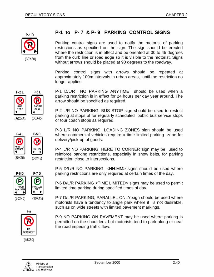
REGULATORY SIGNS CHAPTER 2
September 2000 2.40Ministry ofTransportationand Highways
P-1 to P- 7 & P- 9 PARKING CONTROL SIGNS
Parking control signs are used to notify the motorist of parkingrestrictions as specified on the sign. The sign should be erectedwhere the restriction is in effect and be oriented at 30 to 45 degreesfrom the curb line or road edge so it is visible to the motorist. Signswithout arrows should be placed at 90 degrees to the roadway.
Parking control signs with arrows should be repeated atapproximately 100m intervals in urban areas, until the restriction nolonger applies.
P-1 D/L/R NO PARKING ANYTIME should be used when aparking restriction is in effect for 24 hours per day year around. Thearrow should be specified as required.
P-2 L/R NO PARKING, BUS STOP sign should be used to restrictparking at stops of for regularly scheduled public bus service stopsor tour coach stops as required.
P-3 L/R NO PARKING, LOADING ZONES sign should be usedwhere commercial vehicles require a time limited parking zone fordelivery/pick-up of goods.
P-4 L/R NO PARKING, HERE TO CORNER sign may be used toreinforce parking restrictions, especially in snow belts, for parkingrestriction close to intersections.
P-5 D/L/R NO PARKING, <HH:MM> signs should be used whereparking restrictions are only required at certain times of the day.
P-6 D/L/R PARKING <TIME LIMITED> signs may be used to permitlimited time parking during specified times of day.
P-7 D/L/R PARKING, PARALLEL ONLY sign should be used wheremotorists have a tendency to angle park where it is not desirable,such as on wide streets with limited pavement markings.
P-9 NO PARKING ON PAVEMENT may be used where parking ispermitted on the shoulders, but motorists tend to park along or nearthe road impeding traffic flow.

CHAPTER 2 REGULATORY SIGNS
September 2000 2.41Ministry ofTransportationand Highways
P- 8, P-10 to P-12, P- 14 NO STOPPING SIGNS
NO STOPPING signs indicate to the motorist that stopping isprohibited along the zone specified by the sign. No Stopping signsare effective at all times, on all days of the week. These signs areused where stopping along the curb or shoulder may create ahazard or impede traffic.
The sign should be erected where the restriction is in effect and beoriented at 30 to 45 degrees from the curb line or road edge so it isvisible to the motorist. Signs without arrows should be placed at 90degrees to the roadway.
P-8 and P-8 D/L/R NO STOPPING signs are used to indicate thatstopping is prohibited along the established zone.
P-8 NO STOPPING signs without arrows are 60 x 60 cm indimension and should be only used on freeways and expressways.P-8 signs with arrows are 30 x 30 cm and should be used only onurban arterials.
P-10 EMERGENCY PARKING ONLY signs shall be used whereparking is restricted to only emergency situations and whereadequate parking area exist.
P-11 NO STOPPING ON PAVEMENT signs are used wherestopping is prohibited and where there is a known problem due tomotorists stopping on the traveled portion of the roadway.
P-12 NOT STOPPING ON BRIDGE signs are used to indicate thatstopping is prohibited on the bridge.
P-14 NO STOPPING ON TRACKS signs are used in advance ofrailway crossings to indicate that stopping is prohibited on therailway tracks.

REGULATORY SIGNS CHAPTER 2
September 2000 2.42Ministry ofTransportationand Highways
P-13 NO CAMPING OR OVERNIGHT PARKING
The P13 NO CAMPING OR OVERNIGHT PARKING sign may beused at pullouts, picnic sites, viewpoints, roadside rest stops, etc.wherever such a restrictions may be required to prevent campingor overnight parking.
P-15 PLEASE LIMITED YOUR STAY TO XX HOURS
P-100 EMPLOYEE PARKING ONLY
The P-100 EMPLOYEE PARKING ONLY signs shall be usedwhere only employees of the associated company or agency areallowed to use the marked parking facilities.
P-103 L/R HANDICAPPED PARKING ONLY
P-103 HANDICAPPED PARKING ONLY signs are used to markparking facilities that are reserved for vehicles displaying theapproved handicap placard.
P-104 NO STOPPING AVALANCHE AREA
The P-104 AVALANCHE AREA signs indicate to motorists that anavalanche hazard exists and stopping is prohibited. The W-106AVALANCHE AREA ENDS sign shall be used to mark the end ofthe hazard area.
The P-15 PLEASE LIMITED YOUR STAY TO XX HOURS may beused at MoTH rest stops and pullouts to indicate that the facility isnot intended for long term recreation activities, however it is notintended to restrict commercial vehicle operators from sleeping invehicle cabs.
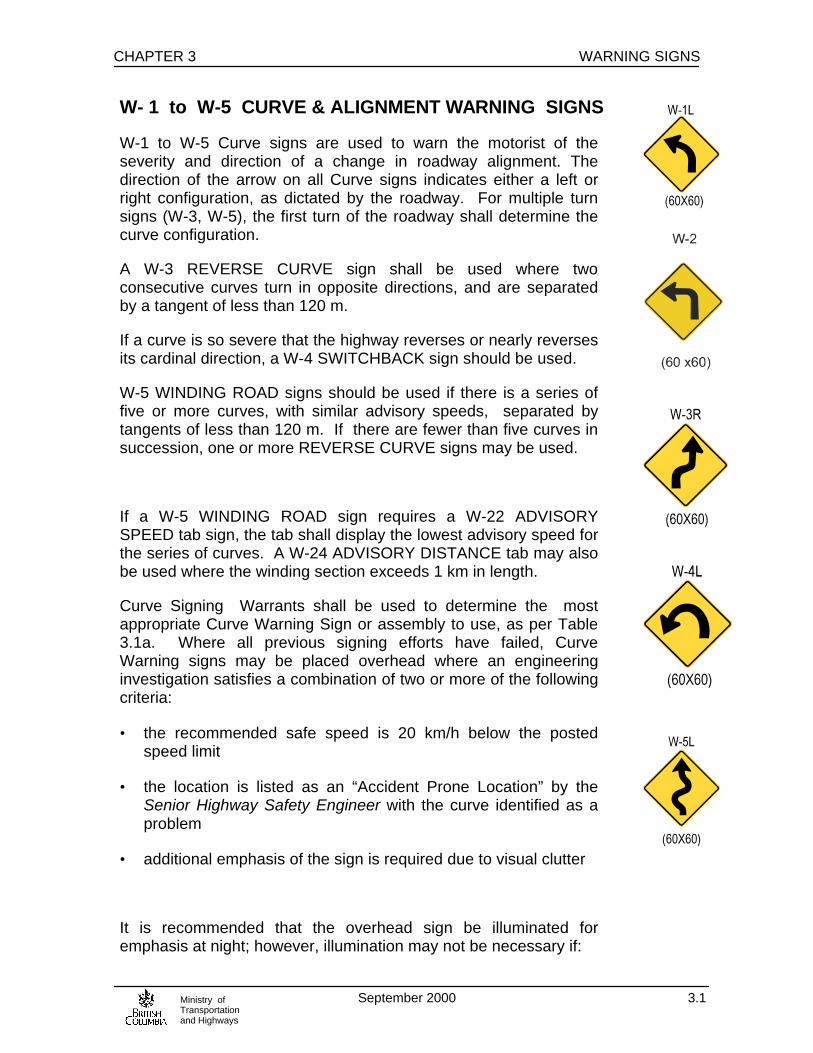
CHAPTER 3 WARNING SIGNS
September 2000 3.1Ministry ofTransportationand Highways
W- 1 to W-5 CURVE & ALIGNMENT WARNING SIGNS
W-1 to W-5 Curve signs are used to warn the motorist of theseverity and direction of a change in roadway alignment. Thedirection of the arrow on all Curve signs indicates either a left orright configuration, as dictated by the roadway. For multiple turnsigns (W-3, W-5), the first turn of the roadway shall determine thecurve configuration.
A W-3 REVERSE CURVE sign shall be used where twoconsecutive curves turn in opposite directions, and are separatedby a tangent of less than 120 m.
If a curve is so severe that the highway reverses or nearly reversesits cardinal direction, a W-4 SWITCHBACK sign should be used.
W-5 WINDING ROAD signs should be used if there is a series offive or more curves, with similar advisory speeds, separated bytangents of less than 120 m. If there are fewer than five curves insuccession, one or more REVERSE CURVE signs may be used.
If a W-5 WINDING ROAD sign requires a W-22 ADVISORYSPEED tab sign, the tab shall display the lowest advisory speed forthe series of curves. A W-24 ADVISORY DISTANCE tab may alsobe used where the winding section exceeds 1 km in length.
Curve Signing Warrants shall be used to determine the mostappropriate Curve Warning Sign or assembly to use, as per Table3.1a. Where all previous signing efforts have failed, CurveWarning signs may be placed overhead where an engineeringinvestigation satisfies a combination of two or more of the followingcriteria:
• the recommended safe speed is 20 km/h below the postedspeed limit
• the location is listed as an “Accident Prone Location” by theSenior Highway Safety Engineer with the curve identified as aproblem
• additional emphasis of the sign is required due to visual clutter
It is recommended that the overhead sign be illuminated foremphasis at night; however, illumination may not be necessary if:

WARNING SIGNS CHAPTER 3
September 2000 3.2Ministry ofTransportationand Highways
• no power source is available to illuminate the sign
• sufficient ambient light is available, e.g. from luminaries.
Simultaneous Flashers may be added to overhead signs where therecommended safe speed is 40 km/h or more below the postedspeed limit, and/or at locations where the accident frequency ishigh.
Approval for overhead curve signs must be obtained from theSenior Traffic Engineer prior to installation.
Installation guideline: Condition C, Table 1, (Appendix).
DETERMINATION OF ADVISORY SPEED FORHORIZONTAL CURVES
The advisory speed at which a curve may be negotiated isdetermined with the aid of an electronic or mechanical inclinometer.This instrument measures and records the lateral gravitation forceson the vehicle as it is driven through the curve.
The advisory speed (which is determined to the nearest 10 km perhour) may be defined as that speed at which the transverseinclination or “bank” of the testing vehicle, plus centrifugal force,reaches a predetermined degree of inclination. The acceptabledegree of inclination varies inversely with the safe speed. SeeTable 3.1b. The procedure to determine the advisory speed is asfollows:
a) Drive through the section to be tested at, or below any advisoryor posted speed limits, and choose a significant landmark(s),such as a cross road name or structure, as a reference for thetest location.
b) Drive through the curve (or series of curves) at the postedadvisory speed, or slightly below the posted legal speed asconditions allow. A rule of thumb is to begin the test at a speed10 km/h below any posted legal or advisory speeds to ensuresafety.
c) Drive through the curve parallel to the centre lane line at aconstant rate of speed without “flattening” the curve.
d) Note the instrument reading for each pass through the curveuntil a reading within the allowable inclination per Table 3.1b isachieved for the posted legal speed category.

CHAPTER 3 WARNING SIGNS
September 2000 3.3Ministry ofTransportationand Highways
e) Advisory speeds are established based on which allowablereading was obtained, relative to the posted legal speed for thesection.
f) Refer to Table 3.1a for the signing treatment appropriate foreach particular situation.
Example: Posted legal speed = 80km/h
Instrument indicates 12° at 80km/h
Instrument indicates 10° at 70km/h
A W-1 sign is warranted since it only required a 10km/h drop in speed to bring the allowable inclination within the limits for the posted speed.
NOTE:The Vehicle used for testing should be an average-sized “family”vehicle with suspension in good condition and tires with averagewear. Winter or deep-tread tires should not be used. Pick-up truckscargo vans, S.U.V.’s are not acceptable test vehicles.
Testing should be done under normal driving conditions, on bareand dry pavement.
On new sections of road, it is desirable to have the lane markingsin place or preliminary marking lines on the pavement beforetesting.
Curve test results will vary for each direction. Note a curve will notalways require signing in both directions.

WARNING SIGNS CHAPTER 3
September 2000 3.4Ministry ofTransportationand Highways
TABLE 3.1a
Legal Speed ADVISORY SPEED (km/h)
Limit (km/h) 90 80 70 60 50 40 30
100 W-1 W-1, W-22 W-21, W-1, W-22 W-21,W-2, W-22
w-21, w-2, W-22 W-21, W-2, W-22 W-21, W-2, W-22
90 W-1 W-1, W-22 W-21, W-1, W-22 W-21, W-2, W-22 W-21, W-2, W-22 W-21, W-2, W-22
80 W-1 W-1, W-22 W-21, W-1, W-22 W-21, W-2, W-22 W-21, W-2, W-22
70 W-1 W-1, W-22 W-21, W-1, W-22 W-21, W-2, W-22
60 W-1 W-1, W-22 W-21, W-1, W-22
Table 3.1bPosted Speed Range (km/h) Max. Allowable
Inclination0-40 14°
41-60 12°61-limit 10°
LEVEL 1 LEVEL 5 OVERHEADW1 to W5 only
LEVEL 2ADD W-22 belowcurve sign
LEVEL 6 OVERHEAD, ILLUMINATEDLEVEL 3ADD W-21 priorto curve sign
LEVEL 4ADD W-23 in placeof W-21
LEVEL 7 OVERHEAD WITH FLASHERSSee individualsign warrants forapplication
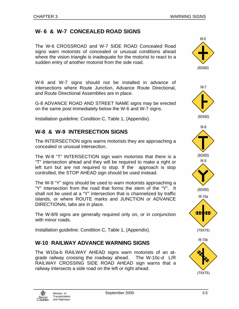
CHAPTER 3 WARNING SIGNS
September 2000 3.5Ministry ofTransportationand Highways
W- 6 & W-7 CONCEALED ROAD SIGNS
The W-6 CROSSROAD and W-7 SIDE ROAD Concealed Roadsigns warn motorists of concealed or unusual conditions aheadwhere the vision triangle is inadequate for the motorist to react to asudden entry of another motorist from the side road.
W-6 and W-7 signs should not be installed in advance ofintersections where Route Junction, Advance Route Directional,and Route Directional Assemblies are in place.
G-8 ADVANCE ROAD AND STREET NAME signs may be erectedon the same post immediately below the W-6 and W-7 signs.
Installation guideline: Condition C, Table 1, (Appendix).
W-8 & W-9 INTERSECTION SIGNS
The INTERSECTION signs warns motorists they are approaching aconcealed or unusual intersection.
The W-8 “T” INTERSECTION sign warn motorists that there is a“T” intersection ahead and they will be required to make a right orleft turn but are not required to stop. If the approach is stopcontrolled, the STOP AHEAD sign should be used instead.
The W-9 “Y” signs should be used to warn motorists approaching a“Y” intersection from the road that forms the stem of the “Y”. Itshall not be used at a “Y” intersection that is channelized by trafficislands, or where ROUTE marks and JUNCTION or ADVANCEDIRECTIONAL tabs are in place.
The W-8/9 signs are generally required only on, or in conjunctionwith minor roads.
Installation guideline: Condition C, Table 1, (Appendix).
W-10 RAILWAY ADVANCE WARNING SIGNS
The W10a-b RAILWAY AHEAD signs warn motorists of an at-grade railway crossing the roadway ahead. The W-10c-d L/RRAILWAY CROSSING SIDE ROAD AHEAD sign warns that arailway intersects a side road on the left or right ahead.

WARNING SIGNS CHAPTER 3
September 2000 3.6Ministry ofTransportationand Highways
The W-10 sign should be placed in advance of all railway at-gradecrossings, even if protected by signals, gates, or flagpersons,except in the following cases:
a) at an infrequently used minor siding or spur crossing that iscontrolled by a flagperson and has a speed limit of 50 km/h orless on the street.
b) in developed urban areas where crossings are fully protectedand the physical conditions are such that suitable signplacement is not practical.
On a divided highway or one-way street, it may be desirable toerect a supplemental sign on the left side of the roadway or withinthe median divider.
The Installation guideline: Condition C, Table 1, (Appendix).
W-11 & W-13 STOP/YIELD AHEAD SIGN
The W-11 STOP AHEAD or W-13 YIELD AHEAD sign warnsmotorists of an upcoming stop or yield condition. This sign shouldbe installed if there is inadequate visibility for safe stoppingdistance or a safe yield maneuver due to conditions such as poorhorizontal or vertical geometry, foliage, parking etc. High approachspeeds may also warrant installation of this sign. The W-11/W-13may also be used for an educational period to warn motorist of anewly installed stop sign or yield sign.
Installation guideline: Condition B, Table 1, (Appendix).
W-12 SIGNAL AHEAD SIGN
The W-12 SIGNAL AHEAD sign warns motorists of the presence oftraffic signals at the intersection ahead.
The W-12 SIGNAL AHEAD sign should be used:
a) where the signals are not visible for a minimum distance of 120m in advance of the intersection
b) where the conditions of visibility, light and backgrounddistractions warrant an advance warning.
If warranted, the W-116 PREPARE TO STOP WHEN AMBERFLASHING will replace the W-12.

CHAPTER 3 WARNING SIGNS
September 2000 3.7Ministry ofTransportationand Highways
A G-8 ADVANCE ROAD AND STREET NAME sign may bemounted immediately below the W12 sign.
Installation guideline: Condition B, Table 1, (Appendix).
W-14 , W-15 , W-16 CHECKERBOARD SIGNS
The W-14 CHECKERBOARD sign warns motorists of thetermination of a road.
A W-15 sign may be used to warn motorists of an abrupt change ofalignment at a turn or curve. The W-15 sign may be configured forleft or right turns by installing the sign in the desired orientation. W-15 signs may be installed alone or in combination with delineatorsand/or other warning signs to mark a very abrupt change inalignment.
W-16 signs should be used at “T” intersections, where they willdirect the traffic that approaches from the roadway forming thestem of the “T”.
W-15 or W-16 oversized Checkerboard signs may be used whereapproach speeds are 70km/h or greater, or where past trafficperformance indicates a need for greater visibility or emphasis.
These signs should be mounted in a diamond shaped orientationso that the black squares occupy the top and bottom cornerpositions.
Checkerboard signs shall be located directly in line with the path ofthe approaching traffic above and behind any barricades.
W-17 ROUNDABOUT SIGN
The W-17 ROUNDABOUT sign warns motorists they areapproaching a roundabout where it would normally not beexpected. If warranted the W-17 should be installed prior to theyield sign at the roundabout in accordance to Condition B, Table 1,(Appendix). Note the W-17 sign is not used to warn of trafficcalming circles in residential areas.
W-17
(60 x 60)
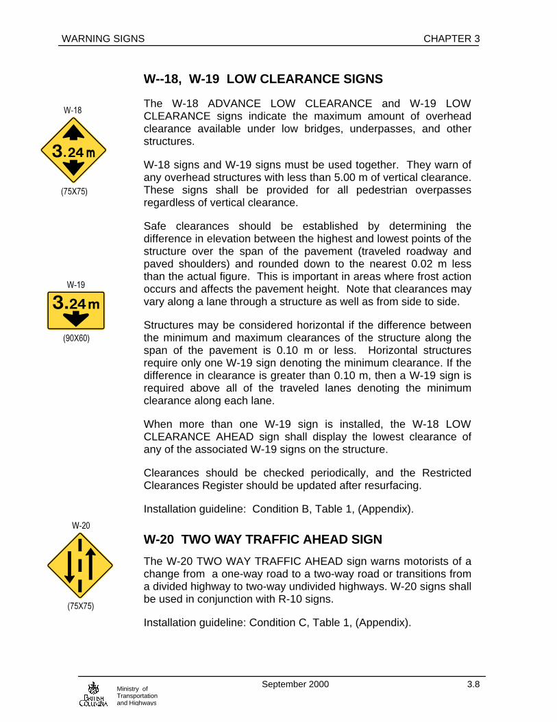
WARNING SIGNS CHAPTER 3
September 2000 3.8Ministry ofTransportationand Highways
W--18, W-19 LOW CLEARANCE SIGNS
The W-18 ADVANCE LOW CLEARANCE and W-19 LOWCLEARANCE signs indicate the maximum amount of overheadclearance available under low bridges, underpasses, and otherstructures.
W-18 signs and W-19 signs must be used together. They warn ofany overhead structures with less than 5.00 m of vertical clearance.These signs shall be provided for all pedestrian overpassesregardless of vertical clearance.
Safe clearances should be established by determining thedifference in elevation between the highest and lowest points of thestructure over the span of the pavement (traveled roadway andpaved shoulders) and rounded down to the nearest 0.02 m lessthan the actual figure. This is important in areas where frost actionoccurs and affects the pavement height. Note that clearances mayvary along a lane through a structure as well as from side to side.
Structures may be considered horizontal if the difference betweenthe minimum and maximum clearances of the structure along thespan of the pavement is 0.10 m or less. Horizontal structuresrequire only one W-19 sign denoting the minimum clearance. If thedifference in clearance is greater than 0.10 m, then a W-19 sign isrequired above all of the traveled lanes denoting the minimumclearance along each lane.
When more than one W-19 sign is installed, the W-18 LOWCLEARANCE AHEAD sign shall display the lowest clearance ofany of the associated W-19 signs on the structure.
Clearances should be checked periodically, and the RestrictedClearances Register should be updated after resurfacing.
Installation guideline: Condition B, Table 1, (Appendix).
W-20 TWO WAY TRAFFIC AHEAD SIGN
The W-20 TWO WAY TRAFFIC AHEAD sign warns motorists of achange from a one-way road to a two-way road or transitions froma divided highway to two-way undivided highways. W-20 signs shallbe used in conjunction with R-10 signs.
Installation guideline: Condition C, Table 1, (Appendix).
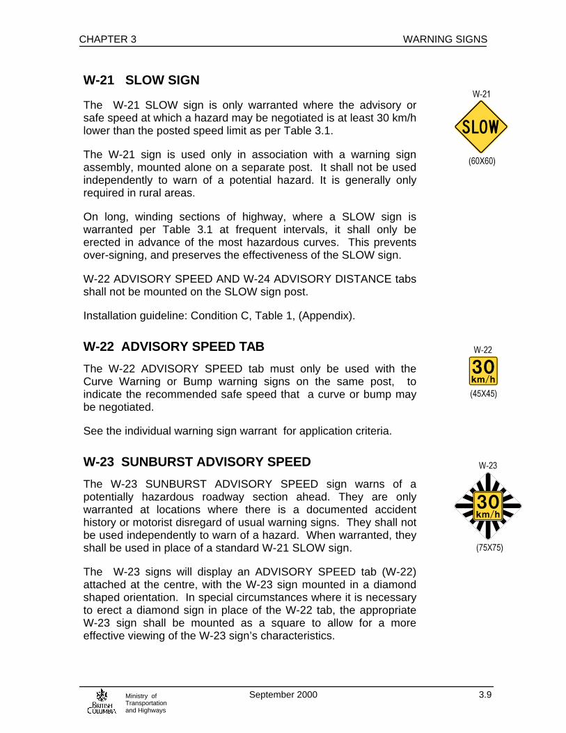
CHAPTER 3 WARNING SIGNS
September 2000 3.9Ministry ofTransportationand Highways
W-21 SLOW SIGN
The W-21 SLOW sign is only warranted where the advisory orsafe speed at which a hazard may be negotiated is at least 30 km/hlower than the posted speed limit as per Table 3.1.
The W-21 sign is used only in association with a warning signassembly, mounted alone on a separate post. It shall not be usedindependently to warn of a potential hazard. It is generally onlyrequired in rural areas.
On long, winding sections of highway, where a SLOW sign iswarranted per Table 3.1 at frequent intervals, it shall only beerected in advance of the most hazardous curves. This preventsover-signing, and preserves the effectiveness of the SLOW sign.
W-22 ADVISORY SPEED AND W-24 ADVISORY DISTANCE tabsshall not be mounted on the SLOW sign post.
Installation guideline: Condition C, Table 1, (Appendix).
W-22 ADVISORY SPEED TAB
The W-22 ADVISORY SPEED tab must only be used with theCurve Warning or Bump warning signs on the same post, toindicate the recommended safe speed that a curve or bump maybe negotiated.
See the individual warning sign warrant for application criteria.
W-23 SUNBURST ADVISORY SPEED
The W-23 SUNBURST ADVISORY SPEED sign warns of apotentially hazardous roadway section ahead. They are onlywarranted at locations where there is a documented accidenthistory or motorist disregard of usual warning signs. They shall notbe used independently to warn of a hazard. When warranted, theyshall be used in place of a standard W-21 SLOW sign.
The W-23 signs will display an ADVISORY SPEED tab (W-22)attached at the centre, with the W-23 sign mounted in a diamondshaped orientation. In special circumstances where it is necessaryto erect a diamond sign in place of the W-22 tab, the appropriateW-23 sign shall be mounted as a square to allow for a moreeffective viewing of the W-23 sign’s characteristics.

WARNING SIGNS CHAPTER 3
September 2000 3.10Ministry ofTransportationand Highways
W-23 signs are restricted. Authorization for this use must beobtained from the Regional Traffic Engineer before they areerected.
See Curve Warning Sign Warrants for applications.
W-24 ADVISORY DISTANCE TAB
The W-24 ADVISORY DISTANCE tab informs motorists that thecondition that the warning sign specifies, exists for a distance of 2km or more length. The distances shown on the tab should beshown in multiples of 1 km.
The W-24 tab shall be mounted immediately below the Warningsign that it supplements or below the W-22 Advisory Speed tab ifone exists.
W-25 ADVISORY EXIT SPEED SIGN
The W-25 ADVISORY EXIT SPEED sign indicates therecommended safe speed on interchange exit ramps where theadvisory speed is 10 km/h or more below the posted speed limit.
Accepted engineering procedures should be used to determine thespeed at which ramp curves may be safely driven.
Where additional advisory speed warning is required on a rampbeyond the gore, a standard curve sign and W-22 ADVISORYSPEED tab combination may also be erected.
W-25 signs should be erected on the ramp near the gore, but notalong the preceding taper. They should be installed on the right-hand side of the ramp. If a ramp curves sharply to the right, anadditional W-25 sign may be erected on the left-hand side of theramp to make the warning more noticeable. A W-11 and W-12sign placed on the left-hand side of the ramp must be at least 30 mfrom the W-25 sign in the gore.
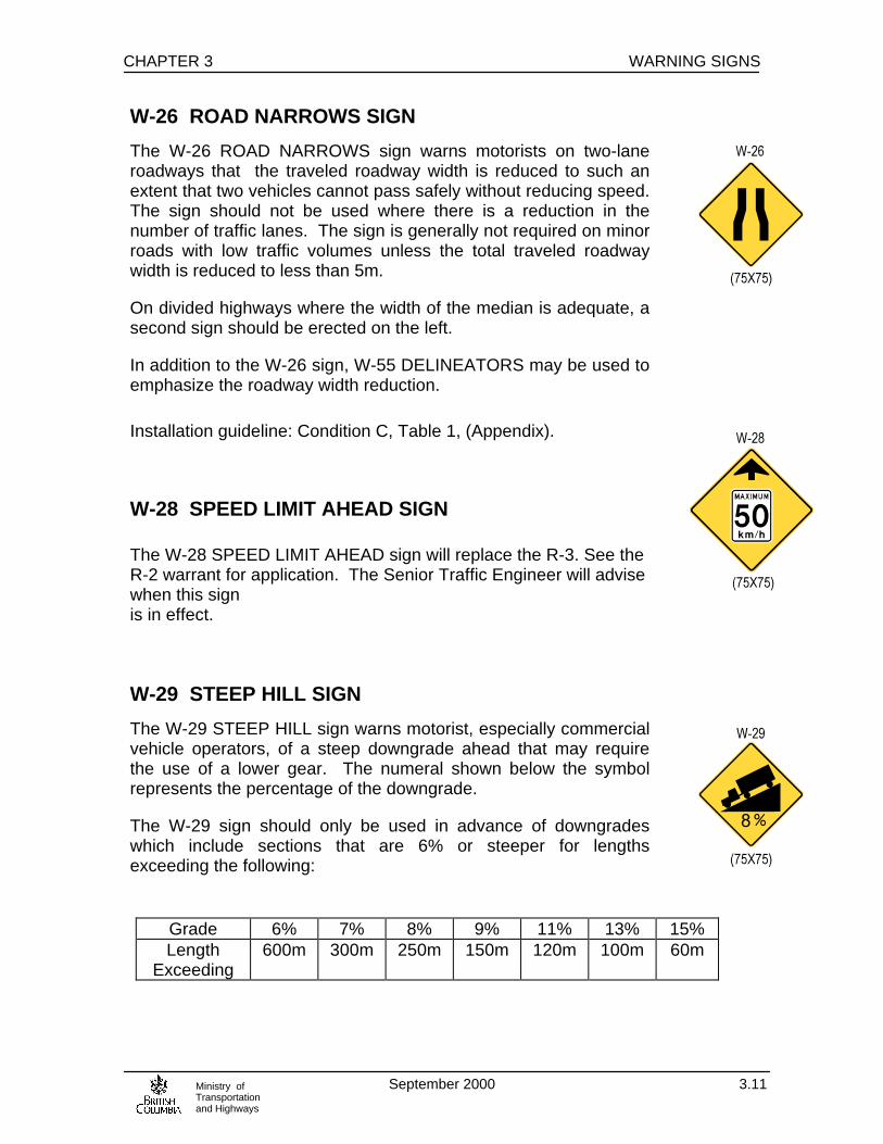
CHAPTER 3 WARNING SIGNS
September 2000 3.11Ministry ofTransportationand Highways
W-26 ROAD NARROWS SIGN
The W-26 ROAD NARROWS sign warns motorists on two-laneroadways that the traveled roadway width is reduced to such anextent that two vehicles cannot pass safely without reducing speed.The sign should not be used where there is a reduction in thenumber of traffic lanes. The sign is generally not required on minorroads with low traffic volumes unless the total traveled roadwaywidth is reduced to less than 5m.
On divided highways where the width of the median is adequate, asecond sign should be erected on the left.
In addition to the W-26 sign, W-55 DELINEATORS may be used toemphasize the roadway width reduction.
Installation guideline: Condition C, Table 1, (Appendix).
W-28 SPEED LIMIT AHEAD SIGN
The W-28 SPEED LIMIT AHEAD sign will replace the R-3. See theR-2 warrant for application. The Senior Traffic Engineer will advisewhen this signis in effect.
W-29 STEEP HILL SIGN
The W-29 STEEP HILL sign warns motorist, especially commercialvehicle operators, of a steep downgrade ahead that may requirethe use of a lower gear. The numeral shown below the symbolrepresents the percentage of the downgrade.
The W-29 sign should only be used in advance of downgradeswhich include sections that are 6% or steeper for lengthsexceeding the following:
Grade 6% 7% 8% 9% 11% 13% 15%Length
Exceeding600m 300m 250m 150m 120m 100m 60m

WARNING SIGNS CHAPTER 3
September 2000 3.12Ministry ofTransportationand Highways
The W-29 sign is also required for hill of any length with a grade of6% or more, combined with horizontal curves of more than 4degrees.
The percent grade shown on the sign should be the average gradeon the section, weighted by distance and rounded up to the nearestwhole number. Adjacent downgrades which are separated bysegments shorter than 200m with grades under 6% should beconsidered as one section.
A separate W-29 sign should be installed in advance of a shorterbut steeper segment, provided the grade verses segment lengthmeets the above criteria.
See Figure 3.1 Signing of Steep Hills and grade calculation
The W-29T TRUCKS GEAR DOWN tab is required under the firstof a group of W-29 signs which indicate steep grades for aparticular hill for which there are no brake check facilities available.
For exceptionally long and steep hills with a high rate of truckaccidents, R-46 TRUCKS STOP HERE - CHECK BRAKES -STEEP HILL AHEAD signs may also be required. W-24ADVISORY DISTANCE tabs may be used with W-29 signs to markdowngrades of 1 km or more in length. In the case of very longdowngrades, it may be desirable to erect intermediate signing atintervals of 1 km or more, especially if the grade on the hill is notuniform. If the W-24 tab is used in conjunction with a W-29 T tab,the W-24 tab should be mounted under the W-29 T tab.
Grade Profile Signs are placed within brake check areas (seeFigure 3.3) in a location where drivers of stopped vehicles caneasily view them. They are intended to show information which willinfluence a driver’s speed selection on the hill. Accordingly, thefollowing information is provided:
• a profile of the relative grades on the hill and a distance scale
• the location of all runaway lanes

CHAPTER 3 WARNING SIGNS
September 2000 3.13Ministry ofTransportationand Highways
Figure 3.1
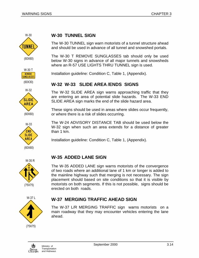
WARNING SIGNS CHAPTER 3
September 2000 3.14Ministry ofTransportationand Highways
W-30 TUNNEL SIGN
The W-30 TUNNEL sign warn motorists of a tunnel structure aheadand should be used in advance of all tunnel and snowshed portals.
The W-30 T REMOVE SUNGLASSES tab should only be usedbelow W-30 signs in advance of all major tunnels and snowshedswhere an R-57 USE LIGHTS THRU TUNNEL sign is used.
Installation guideline: Condition C, Table 1, (Appendix).
W-32 W-33 SLIDE AREA /ENDS SIGNS
The W-32 SLIDE AREA sign warns approaching traffic that theyare entering an area of potential slide hazards. The W-33 ENDSLIDE AREA sign marks the end of the slide hazard area.
These signs should be used in areas where slides occur frequently,or where there is a risk of slides occurring.
The W-24 ADVISORY DISTANCE TAB should be used below theW-32 sign when such an area extends for a distance of greaterthan 1 km.
Installation guideline: Condition C, Table 1, (Appendix).
W-35 ADDED LANE SIGN
The W-35 ADDED LANE sign warns motorists of the convergenceof two roads where an additional lane of 1 km or longer is added tothe mainline highway such that merging is not necessary. The signplacement should based on site conditions so that it is visible bymotorists on both segments. If this is not possible, signs should beerected on both roads.
W-37 MERGING TRAFFIC AHEAD SIGN
The W-37 L/R MERGING TRAFFIC sign warns motorists on amain roadway that they may encounter vehicles entering the laneahead.

CHAPTER 3 WARNING SIGNS
September 2000 3.15Ministry ofTransportationand Highways
The W-37 sign shall be installed on the side of the roadway onwhich merging traffic will be encountered, and positioned so as notto obstruct the driver’s view of those vehicles about to merge.
W-37 signs are not required at intersections that have raised,channelizing islands.
W-38 MERGE SIGN
The W-38 MERGE sign warns motorists facing the sign that theymust merge into another traffic lane ahead.
The W-38 sign shall be used at freeway/expressway on-ramps (orother such one-way approaches that merge with a major road at asmall angle), provided that the available parallel distance on theramp is sufficient to allow a vehicle to reach the highway postedspeed before leaving the ramp and entering the outer through laneof the freeway/expressway. If this condition is not met, then a R-2YIELD sign shall be used instead of a W-38 sign.
The W-38 sign shall be placed on the on-ramp as far as possibleahead of the merge area. The W-38 sign is not a substitute for theW-61 LANE END sign. See the W-61 for its applications.
W-41 SLIPPERY ROAD SIGNS
The W-41 SLIPPERY ROAD sign should be used to warn motoristsin advance of sections of roadways and bridges which becomehazardous under wet or cold climatic conditions. The appropriatetab for conditions encountered must be used with this sign.
The use of these signs shall be kept to an absolute minimum, andupon the correction of the slippery condition, the sign should bepromptly removed.
When the W-41 sign is used to indicate hazardous roadwaysections greater than 1 km in length, a W-24 ADVISORYDISTANCE tab should be mounted below the Warning sign.
Confirmatory signs on long slippery sections should be placedapproximately 3 km apart.
Installation guideline: Condition C, Table 1, (Appendix).

WARNING SIGNS CHAPTER 3
September 2000 3.16Ministry ofTransportationand Highways
W-42 WATCH FOR ROCKS/DEBRIS ON ROAD SIGN
The W-42 WATCH FOR ROCK or DEBRIS ROAD sign warnsmotorists of the possible hazards of falling rock or debrisaccumulation on the roadway.
These signs may be repeated for emphasis along sections of suchroadways. Where this hazard extends for a distance of greaterthan 1 km, W-24 ADVISORY DISTANCE tabs should be used inconjunction with the W-42 signs.
If maintenance records indicate that substantial quantities of debrisroutinely falls causing either partial or full lane closure, the W-42sign should be replaced with the W-32 SLIDE AREA sign.
Installation guideline: Condition C, Table 1, (Appendix).
W- 44, W-45, W-46 LIVESTOCK SIGNS
The W-44 WATCH FOR LIVESTOCK, W-45 CATTLE CROSSINGand W-46 CATTLEGUARD signs warn motorists of domesticatedanimal crossing hazards.
The W-44 sign should be erected in open-range areas where cows,horses, or other domesticated animals are known to stray over orgather on the highway.
Before W-44 signs are erected in a new open-range area, theMinistry of Agriculture, Fisheries and Food and the BritishColumbia Beef Cattle Growers’ Association should be consultedregarding placement of the signs. Signing itself is the responsibilityof the Ministry of Transportation and Highways.
A W-24 ADVISORY DISTANCE tab, mounted below the W-44, isused to indicate the length of the highway within the open-rangearea. Where open-range sections are over 5 km in length,confirmatory W-44 signs (without W-24 tabs) should be erectedapproximately 3 km apart.
The W-45 sign is required at locations where cattle frequently crossa highway. If the cattle crossing is used infrequently, permanentlymounted signs are not necessary, and the cattle owner shall beresponsible for the placement of temporary signs on the shoulderas required. Such signs shall only be in place while cattle arecrossing the highway.

CHAPTER 3 WARNING SIGNS
September 2000 3.17Ministry ofTransportationand Highways
For information regarding cattle drives, please refer to the Ministry’sCattle Drives on Highways interim policy.
The W-46 sign should be used to warn motorists at all cattle guardlocations. If sight conditions require a reduction in speed of 20km/h or more, a W-22 ADVISORY SPEED tab should be usedbelow the W-46 sign.
Installation guideline: Condition C, Table 1, (Appendix).
W- 48 DIVIDED HIGHWAY ENDS SIGN
The W-48 DIVIDED HIGHWAY ENDS sign warns motorists of animpending transition from divided highway operation to undividedhighway operation.
This sign shall only be used on multi-lane highways. For singlelane two-way highways, R-10 TWO WAY TRAFFIC and W-20TWO WAY TRAFFIC AHEAD signs should be used instead.
This sign shall not be used at a channelized intersection or in placeof the R-14 KEEP RIGHT sign.
When the W-48 sign is installed, it should be oriented in such away as to have the median symbol in the bottom corner.
Installation guideline: Condition C, Table 1, (Appendix).
W-49 PAVEMENT ENDS SIGN
The W-49 PAVEMENT ENDS sign warns motorists of a changefrom paved (asphalt, concrete, or other finished pavement surface)to a gravel or dirt section beginning.
Installation guideline: Condition C, Table 1, (Appendix).
W- 50 NO CENTRE LINE SIGN
The W-50 NO CENTRELINE sign warns motorists of the absenceof centreline pavement marking on the road surface ahead.
This sign should be used on completed re-surfaced new roadwayprojects when it is anticipated that a centreline will not be paintedimmediately.
The W-50 sign shall not be used to indicate the end of a pavedsection of highway.

WARNING SIGNS CHAPTER 3
September 2000 3.18Ministry ofTransportationand Highways
Installation guideline: Condition C, Table 1, (Appendix).
W- 51 NARROW STRUCTURE SIGN
The W-51 NARROW STRUCTURE sign warns motorists of astructure ahead that is narrower than the approach roadway.
This sign should be used in advance of bridges, tunnels, and othernarrow structures. Depending on the roadway conditions, the W-51 and W-51T shall be used as shown in Figure 8.4 in Part ‘B’. AR-56 YIELD TO ONCOMING TRAFFIC is required when W-51Ttabs are used.
Installation guideline: Condition B, Table 1, (Appendix).
W- 54 OBJECT MARKERS
The W-54 DOUBLE OBJECT MARKER and W-54 L/RLEFT/RIGHT OBJECT MARKERS warn motorists of objects orobstructions on the roadway.
Object markers should be used to mark obstructions whichencroach on a shoulder or the traveled roadway; for example,
a) On left and right bridge end posts that encroach on the shoulderor the traveled roadway
b) the diverging end of traffic islands which face, and are adjacentto oncoming traffic
c) the end of the guardrail flare (or ‘hinge’ point of the barriertreatment)
The W-54 L is used to mark obstructions on a motorist’s left andthe W-54 R to mark obstructions on the right. Where traffictraveling in one direction is allowed to proceed both to the left andto the right of an obstruction, a W-54 DOUBLE OBJECT marker isrequired.
W-54 L & R signs should be positioned with the inside edge of themarker in line with the inside edge of the object. On bridges withsidewalks, the marker should be installed with the inside edge 0.4m back of the curb face. For bridges without sidewalks, the insideedge of the marker shall be in line with the inside edge of thebridge rail end post. However, where a concrete barrier is locatedat the end of the sidewalk and in line with the curb face, the objectmarker shall be mounted with its inside edge in line with the inside

CHAPTER 3 WARNING SIGNS
September 2000 3.19Ministry ofTransportationand Highways
edge of the concrete barrier. Refer to Figure 1.2 installation formore details.
Object markers should be mounted on posts immediately inadvance of the obstruction being identified, and generallypositioned with the bottoms of the markers about 1.0 m above thelevel of the traveled roadway. If markers erected at this height ontraffic islands impair sight distance, then the mounting height maybe reduced so that the bottoms of the markers are 0.5 m abovepavement level.
When a Object marker is mounted below and on the same post asanother standard sign, the mounting height of the marker isgoverned by the standard mounting height of the upper sign.Where a W-54L OBJECT MARKER is mounted below a R-14 sign,it is permissible to centre the W-54 between the R-14 and thepavement level.
Object marker stripes slope downward towards the side or sides ofthe obstruction on which traffic is allowed to pass.
W-55 DELINEATOR SIGNS
REFER TO CHAPTER 7, SECTION 7.6 DELINEATORS
W-61 RIGHT/LEFT LANE ENDS SIGN
The W-61 RIGHT/LEFT LANE ENDS sign indicates a reduction inthe number of lanes of pavement ahead either from the right orfrom the left.
The W-61 sign is only used for the reduction of a group ofcontinuous lanes, and, therefore, should not be used in advance ofan acceleration lane.
Pavement markings and/or delineation markers may also be usedto mark the transition.
The appropriate version of the sign shall be used for the specificroadway configuration, that is, the W-61 R shall be used when theright lane ends, and the W-61 L when the left lane ends.
The oversize version of these signs should be used on multi-lanefacilities, or wherever greater emphasis is required.
Refer to Figure 7.37 for installation guidelines.

WARNING SIGNS CHAPTER 3
September 2000 3.20Ministry ofTransportationand Highways
W-62 CHEVRON SIGN
The W-62 CHEVRON sign provides motorists with additionalguidance as to changes in the horizontal alignment of the roadway.
W-62 signs may be used in addition to normal curve warning signs,to indicate sharp changes in the horizontal alignment of a road.Other signs which should also be considered in the treatment ofsuch special situations are the W-55 DELINEATORS the W-23SUNBURST, and the W-15 CHECKERBOARD signs. A typicalexample of a where W-62 signs may be required is a sharp curveat the end of a long tangent.
The W-62 shall not be used to mark obstructions such as medians,overpass piers, etc.
W-62 signs should be installed on the outside of a curve, at rightangles to approaching traffic, with the lower edge 1.2 m above thenearest edge of a traveled lane.
Spacing between W-62 signs should be such that the motoristalways has two signs in view until the change of alignmenteliminates the need for signs. A minimum of three W-62 signsshall be placed on a curve.
W-62 signs should be mounted with the same specifications asW-15 SINGLE ARROW CHECKERBOARD signs.
W-63 & W-64 WATCH FOR WILD ANIMALS SIGNS
The W-63 WATCH FOR MOOSE and W-64 WATCH FOR DEERsigns warn motorists of known wild animal crossings or knownsections where animals may be present on or along the highwaycreating a hazard.
Where there is history of moose related accidents the W-63 signshall be used.
Where there is history of deer related accidents the W-64 sign shallbe used.

CHAPTER 3 WARNING SIGNS
September 2000 3.21Ministry ofTransportationand Highways
If the crossing area covers a distance of greater than 1 km, a W-24ADVISORY DISTANCE tab shall be used. Intermediate W-63/64signs (without W-24 tabs) may be required for long segments ofanimal crossings, but such signs should not be more than 8 kmapart.
Intermediate warning signs without W-24 tabs may be requiredwhere wild animals are known to cross randomly along aconsiderable length of road. Additional signs may be required ifthere are intervening intersections from which significant volumesof traffic enter the main road.
The oversize versions of these signs should be used on multi-laneroadways, or where special emphasis is required.
Installation guideline: Condition C, Table 1, (Appendix).
W-106 END AVALANCHE AREA SIGN
The W-106 END AVALANCHE AREA sign should be used withthe P-104 NO STOPPING AVALANCHE AREA sign to indicate theend of the avalanche danger.
W-107 DIP IN ROAD SIGN
The W-107 DIP sign warns motorists of a depression in theroadway ahead.
This sign may be used in advance of a depression in the roadwaywhich could cause cargo to shift, or a vehicle to veer from itscourse.
Installation guideline: Condition C, Table 1, (Appendix).

WARNING SIGNS CHAPTER 3
September 2000 3.22Ministry ofTransportationand Highways
W- 108 BUMP/ ROUGH ROADWAY SIGN
The W-108 BUMP sign warns of a bump or rough roadway ahead.
The W-108 sign should be used to warn of sudden changes in theroad surface which can create a potentially dangerous condition.Such areas include frost heaves, fill settlements, short pot-holedsections, etc. where such objects are likely to remain for extendedperiods of time and exceed 15 m in length.
For sections over 1 km in length, W-24 ADVISORY DISTANCEtabs should be used in conjunction with the W-108 or W-310 sign.W-22 ADVISORY SPEED tabs should be used as outlined undertheir own application guidelines.
The C-16 TEMPORARY HAZARD MARKER OR C-25TEMPORARY BUMP sign may be used for short durationconditions per Traffic Control Manual for Work on Roadways.
Installation guideline: Condition C, Table 1, (Appendix).
W- 114 LOW FLYING AIRCRAFT SIGN
The W-114 LOW FLYING AIRCRAFT sign warns motorists of lowflying aircraft within the vicinity of the road.
This signs should be used where low flying aircraft may causedifficulties for road users through excessive noise or visualdistraction. Potential locations for this sign are roadways nearairports, or wherever the aircraft approach envelope is low.
Installation guideline: Condition C, Table 1, (Appendix).
W-115 METAL BRIDGE DECK SIGN
The W-115 sign should be used to warn motorists, especiallymotorcyclists, of a bridge ahead that has a metal deck and may beslippery .
W-115
(60 x 60)
W-115T
(45 x 30)
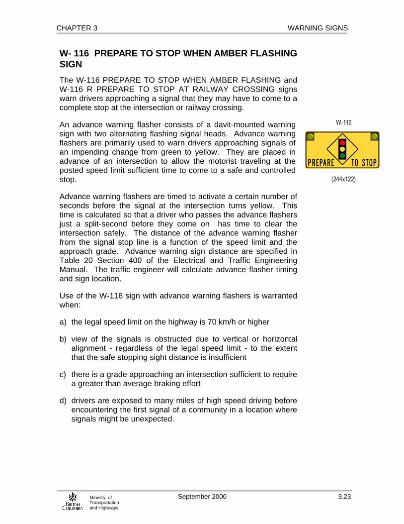
CHAPTER 3 WARNING SIGNS
September 2000 3.23Ministry ofTransportationand Highways
W- 116 PREPARE TO STOP WHEN AMBER FLASHINGSIGN
The W-116 PREPARE TO STOP WHEN AMBER FLASHING andW-116 R PREPARE TO STOP AT RAILWAY CROSSING signswarn drivers approaching a signal that they may have to come to acomplete stop at the intersection or railway crossing.
An advance warning flasher consists of a davit-mounted warningsign with two alternating flashing signal heads. Advance warningflashers are primarily used to warn drivers approaching signals ofan impending change from green to yellow. They are placed inadvance of an intersection to allow the motorist traveling at theposted speed limit sufficient time to come to a safe and controlledstop.
Advance warning flashers are timed to activate a certain number ofseconds before the signal at the intersection turns yellow. Thistime is calculated so that a driver who passes the advance flashersjust a split-second before they come on has time to clear theintersection safely. The distance of the advance warning flasherfrom the signal stop line is a function of the speed limit and theapproach grade. Advance warning sign distance are specified inTable 20 Section 400 of the Electrical and Traffic EngineeringManual. The traffic engineer will calculate advance flasher timingand sign location.
Use of the W-116 sign with advance warning flashers is warrantedwhen:
a) the legal speed limit on the highway is 70 km/h or higher
b) view of the signals is obstructed due to vertical or horizontalalignment - regardless of the legal speed limit - to the extentthat the safe stopping sight distance is insufficient
c) there is a grade approaching an intersection sufficient to requirea greater than average braking effort
d) drivers are exposed to many miles of high speed driving beforeencountering the first signal of a community in a location wheresignals might be unexpected.

WARNING SIGNS CHAPTER 3
September 2000 3.24Ministry ofTransportationand Highways
W-116R PREPARE TO STOP AT RAILWAYCROSSING SIGN
The W-116R sign warns motorists they must stop at the railwaycrossing if the amber lights are flashing.
Without restricting the intended usage, the W-116 R sign may beconsidered for the following locations:
a) signalized crossings on roadways with a speed limit of 70 km/hor greater
b) signalized crossings where stopping sight distance is insufficient
c) signalized crossings at the bottom of a hill or downgrade ofconsiderable length
d) signalized crossings where environmental conditions frequentlyrestrict visibility (i.e. fog or sunset glare)
If power is unavailable, it may necessary to consider an alternateadvance warning strategy. Contact the Regulatory Liaison Officer,Bridge Section, Engineering Branch.
On federally chartered railways, federal grants may be available forinstallation.
W-116 signs shall be mounted overhead per Table 20 Section 400of the Electrical and Traffic Engineering Manual.
The installation and location of these devices requires the approvalof the Regional Traffic Engineer.
W- 121 ROAD SUBJECT TO FLOODING SIGN
The W-121 ROAD SUBJECT TO FLOODING sign warns motoristsof possible roadway flooding ahead.
This sign should be used on roadways where frequent or seasonalflooding of the roadway occurs. This sign should only be requiredwhen the flooding condition is due to roadway characteristicswhich cannot feasibly be corrected due to technical or financialreasons.
Where possible, the flooding problem should be remedied ormitigated.
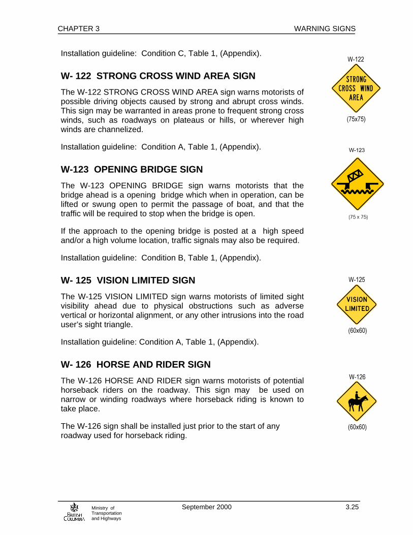
CHAPTER 3 WARNING SIGNS
September 2000 3.25Ministry ofTransportationand Highways
Installation guideline: Condition C, Table 1, (Appendix).
W- 122 STRONG CROSS WIND AREA SIGN
The W-122 STRONG CROSS WIND AREA sign warns motorists ofpossible driving objects caused by strong and abrupt cross winds.This sign may be warranted in areas prone to frequent strong crosswinds, such as roadways on plateaus or hills, or wherever highwinds are channelized.
Installation guideline: Condition A, Table 1, (Appendix).
W-123 OPENING BRIDGE SIGN
The W-123 OPENING BRIDGE sign warns motorists that thebridge ahead is a opening bridge which when in operation, can belifted or swung open to permit the passage of boat, and that thetraffic will be required to stop when the bridge is open.
If the approach to the opening bridge is posted at a high speedand/or a high volume location, traffic signals may also be required.
Installation guideline: Condition B, Table 1, (Appendix).
W- 125 VISION LIMITED SIGN
The W-125 VISION LIMITED sign warns motorists of limited sightvisibility ahead due to physical obstructions such as adversevertical or horizontal alignment, or any other intrusions into the roaduser’s sight triangle.
Installation guideline: Condition A, Table 1, (Appendix).
W- 126 HORSE AND RIDER SIGN
The W-126 HORSE AND RIDER sign warns motorists of potentialhorseback riders on the roadway. This sign may be used onnarrow or winding roadways where horseback riding is known totake place.
The W-126 sign shall be installed just prior to the start of anyroadway used for horseback riding.

WARNING SIGNS CHAPTER 3
September 2000 3.26Ministry ofTransportationand Highways
W-128 DIVIDED HIGHWAY AHEAD SIGN
The W-128 DIVIDED HIGHWAY AHEAD tab sign indicates tomotorists that they are approaching an intersection with a dividedhighway. This sign should be used in advance of four-lane dividedhighways with “at grade” intersections, where the minor road iscontrolled by an R-1 STOP sign.
The W-128T tab may temporarily be used with the W-128 sign foran educational period.
Installation guideline: Condition B, Table 1, (Appendix).
W- 129 CYCLIST CROSSING SIGN
The W-129 CYCLIST CROSSING warns motorists of a bike routecrossing a roadway.
Installation guideline: Condition B, Table 1, (Appendix).
W-130 CYCLISTS ON ROADWAY SIGN
The W-130 CYCLIST ON ROADWAY warns both motorists andcyclists that both may be present on the roadway. This sign shouldbe used where the presence of cyclists would be unexpected by themotorist, or where there is heavy volumes of cycling traffic on theroute.
W- 131 CYCLIST WARNING SIGNThe W-131 CYCLIST WARNING sign warns cyclists of apotentially hazardous road condition ahead.
The appropriate W-132 to W-136 tab should be used to identify thenature of the hazard.
W-131 signs shall be erected just prior to the hazard, subject topractical field limitations.

CHAPTER 3 WARNING SIGNS
September 2000 3.27Ministry ofTransportationand Highways
W- 132 to W-136 CYCLIST WARNING TABS
The W-132 SLIPPERY WHEN WET and W-133 SLIPPERY WHENFROSTY tab signs warn cyclists of potentially hazardous wet andfrosty road conditions.
The W-134 GROOVED BRIDGE DECK tab sign warns cyclists thatthe bridge deck is grooved, and may result in a loss of control.
The W-135 CYCLISTS USE CAUTION tab sign warns cyclists of ahazard ahead.
The W-136 CYCLIST WARNING - UNEVEN ROAD tab sign warnscyclists that the road surface is rough and may be hazardous.
Cyclist Warning Tab signs shall only be used with the W-131CYCLIST WARNING sign. They shall be installed immediatelybelow the appropriate warning sign.
If the cyclist hazard is not described by the W-132, W-133 W-136or W-134 tabs the W-135 tab may be used as a generic warning tocyclists to proceed with caution.
W-140 RESERVED LANE AHEAD SIGN
The W-140 RESERVED LANE AHEAD sign warns motorist that alane ahead is reserved for use by special vehicles or vehicles withspecific minimum occupancy levels. The exact nature of therestrictions will be identified on regulatory signs.
The W-140T tab may be used with this sign to specify times of dayand days of week when the restriction applies.
W-140 T
(60 x 30)

WARNING SIGNS CHAPTER 3
September 2000 3.28Ministry ofTransportationand Highways
W-145 NO EXIT SIGN
The W-145 NO EXIT sign should be erected at the entrance tonon-through roads. The W-145 may be installed on the back sideof the R-1 STOP side facing traffic entering the side road.
The W-145a tab may be mounted below the W-145 sign to warndrivers of large vehicles that it may be difficult to turn around at theend of the road.
If the W-145a tab is used, the W-145 sign and tab must bemounted on a separate post and oriented in such a way that it isnot visible to motorists approaching the R-1 STOP sign on the sideroad.
See also G-123 DEAD END sign.
W-314 FARM VEHICLES SIGN
The W-314 FARM VEHICLE sign warns motorists that farmvehicles may be crossing the highway or travelling along theshoulder for short distances when moving between fields.
Installation Guideline: Condition C, Table 1, (Appendix).
W- 316 LOGGING TRUCK SIGNS
The W-316 LOGGING TRUCKS sign warns motorists that loggingtrucks are operating within the area and may crossing or enteringor using the roadway ahead, creating a potentially hazardoussituation.
This sign should only be used where a high percentage of thevehicles using the roadway are logging trucks.
Oversize W-316 signs may be used where additional emphasis isrequire, such as on high-speed facilities. Oversize W-316 signs arerestricted in use.
If installed on logging truck routes, confirmatory W-316 signsshould be installed at 5km intervals.
Installation guideline: Condition A, Table 1, (Appendix).
W-145
W-145 a
(45 x 45)
(45 x 30)
W-314
(75 x 75)

CHAPTER 3 WARNING SIGNS
September 2000 3.29Ministry ofTransportationand Highways
W- 317 TRUCK CROSSING/TURNING AHEAD SIGNS
The W-317 TRUCK TURNING/CROSSING AHEAD sign warnsmotorists that trucks or heavy equipment may be frequentlyentering, crossing or turning from or onto the roadway aheadcreating a potentially hazardous situation.
These signs shall be used in conjunction with the R-20 NOPASSING FOR 150 METRES sign on highways where pavementmarkings indicate that overtaking is permitted.
If the truck/equipment movement is not in progress, these signsmust be removed or covered. Right or left versions of this signshould be used to indicate the direction from which vehicles maybe entering the highway.
Installation guideline: Condition A, Table 1, (Appendix).
W- 318 FIRE TRUCK ENTRANCE SIGN
The W-318 FIRE TRUCK ENTRANCE sign warns motorists of afire station access ahead. Fire trucks infrequently egress oringress the station, creating a hazard to motorists, especially whenblocking the roadway when backing-in.
This sign should be used at all fire truck entrances even if a firesignal exists.
The W-318T tab shall only be used temporarily for an educationalperiod.
The appropriate right or left version of the W-318 sign, indicatingthe direction from which the fire trucks enter the roadway, shouldbe installed per Condition B, Table 1, (Appendix).
W-320 ROAD SUBJECT TO DENSE FOG SIGN
The W-320 ROAD SUBJECT TO DENSE FOG sign warnsmotorists of the potential hazard of dense fog on the roadway.This sign may be used in areas prone to frequent occurrences ofdense fog throughout the year; for example, valleys, or near bodiesof water prone to foggy conditions.
Installation guideline: Condition A, Table 1, (Appendix).

WARNING SIGNS CHAPTER 3
September 2000 3.30Ministry ofTransportationand Highways
W-321 RESERVED LANE CROSSING SIGN
The W-321 RESERVED LANE CROSSING sign warns motorists ofthe existence of a near-side reserved lane, and indicates that aright turn should be completed in the lane adjacent to the reservedlane.
The W-132 sign should be used on the approach to a roadway witha reserved lane if right turns are permitted.
This sign may be temporarily used for an educational period whenthe reserved lane is initially installed or permanently in locationswhere there is a high violation rate for vehicles entering thereserved lane from an intersecting roadway.
W- 322 RUNAWAY LANE AHEAD SIGN
The W-322 TRUCK LANE AHEAD XXXm sign warns motorists,specifically commercial vehicle operators, that an approved, andadequately designed run-away lane facility is located ahead.
This sign should be placed at either 500 m or 1000 m points fromthe entrance to the runaway lane.
Under special circumstances, these distances may be modified inconsultation with the Regional Traffic Engineer to suit fieldconditions.
See Figure 3.2 for typical signing layout.
W-323 RUNAWAY LANE ENTRANCE SIGN
The W-323 RUNAWAY LANE sign is used at the entrance of therunaway lane located on both sides of the lane.
For runaway lanes to the left of the roadway, a left hand version ofthis sign may be used on approval of the Senior Traffic Engineer.See also the W-327 sign.
The W-323 runaway lane entrance sign shall be erected at thebeginning of the taper to the runaway lane.

CHAPTER 3 WARNING SIGNS
September 2000 3.31Ministry ofTransportationand Highways
W-324 TRUCK ROLLOVER WARNING SIGN
Senior Traffic Engineer approval required for installation.
W-325 SLOW TRUCKS USE 4-WAY FLASHERS ONGRADE SIGN
The W-325 SLOW TRUCKS USE 4-WAY FLASHERS ON GRADEwarning sign advises commercial vehicle operators and other largevehicles to use their 4-way flashers when traveling downhill to alertother motorists of the speed differential between their vehicle andthe other vehicles.
This sign may be used on grades where the operating speed oflarge trucks is expected to drop 30 km/h or more below the postedspeed limit.
It is restricted in use, and should be used on high speed, multi-lanehighways or freeways only under the authorization of the SeniorTraffic Engineer in consultation with Highway Safety Section.
This sign should be installed at the start of and intermittently alongsteep and/or long grades.
W-326 TRUCK ADVISORY SPEED SIGN
The W-326 SUGGESTED TRUCK SPEED warning sign advisescommercial vehicle operators and other large vehicles operators ofthe maximum safe descent speed down steep grades.
The safe descent speed is determined by analyzing the relationshipbetween the mass of the vehicle and the length and steepness ofthe grade verses vehicle brake temperature. Contact the SeniorHighway Safety Engineer for evaluation of the advisory descentspeed limit.
The W-326 sign should be installed prior to the commencement ofthe grade.
W-326
(90 x 120)
W-326 T
(90 x 30)

WARNING SIGNS CHAPTER 3
September 2000 3.32Ministry ofTransportationand Highways
W-327 RUNAWAY TRUCK CROSSING SIGN
The W-327 RUNAWAY TRUCK CROSSING sign warns of thepossibility of runaway trucks crossing the roadway in order to utilizea runaway lane facility located on the left hand side of the down-grade traffic.
Use of the W-327 sign requires Senior Traffic Engineer approval.
W-327 sign assemblies shall be installed per Condition A, Table 1,(Appendix), in advance of the runaway lane taper for uphill traffic,or 300 m in advance of the taper if the W-327T tab is used.
W-329 NEW TAB
The W-329 NEW tab should be used with the W-12 sign for newsignal installations. The NEW tab should remain in place for threemonths until motorists become familiar with the signal. If the signalhas W-116 ADVANCE WARNING flashers, the W-329 and W-12signs must be removed after the three month education periodterminates. The W-329 may also be used with any other standardsign to draw attention to revisions in traffic control.
___________________________________________
Grade Profile Sign: (Custom Sign)
Supply grade profile information to the Provincial Sign Designer.

CHAPTER 3 WARNING SIGNS
September 2000 3.33Ministry ofTransportationand Highways
Figure 3.2 Runaway Lane Signing
A) Right Runaway Lane:
B) Left Runaway Lane
W-323R W-323R


CHAPTER 3 WARNING SIGNS
September 2000 3.35Ministry ofTransportationand Highways
Figure 3.3 Conventional Highway Brake Check
R-052
I-175
R-0
45
600m (typical)


CHAPTER 3 WARNING SIGNS
September 2000 3.37Ministry ofTransportationand Highways
Figure 3.4 Freeway Brake Check
R-052
I-175
G-1
28X
R-0
45X
1200m (typical)
600m (typical)

CHAPTER 4 GUIDE SIGNS
Ministry ofTransportationand Highways September 2000 4.1
4.1 INTRODUCTION
Guide signs provide motorists with information on direction anddistance to destinations on their selected route of travel. The designand layout of guide signs should be directed at the motorist who isunfamiliar with the area and consequently requires clear, concise andconsistent sign messaging so they are able to navigate to theirdestination in an orderly manner.
Directional guide signs such as G-1 and G-5 signs are used inadvance of major intersections or junctions to indicate the directionto a destination; confirmatory distance signs such as the G-6 signsare used beyond intersections and major junctions to indicate thedistance in kilometers to the next destination and majordestination/control city. Route markers such as G-10 signs areerected at consistent intervals along a highway as route confirmation.
Guide sign messaging must be clear and simple and use onlywarranted destinations. They should not be used to satisfy politicaldesires or to provide ‘advertising’ for communities.
4.2 CONTROL CITY & DESTINATIONSELECTION POLICY
The destinations shown on guide signs must be significant enough toallow the traveler to navigate the highway system in and beyond theprovince. “Control cities,” “major destinations” and “next destination”are defined in this chapter to provide consistency in guide signmessaging. Control cities and major destinations are identified onMap 4.1 .
Control cities are major traffic generators or destination pointsthroughout the province and in adjoining provinces, territories orstates. These cities or destinations are generally known to mostmotorists and are separated by long distances. Control cities shouldappear on all successive guide signs throughout the length of a givenroute until that destination is reached. Control cities should be:
• identified as pull-through destinations on freeway guide signs • used at route diverge points on freeways

GUIDE SIGNS CHAPTER 4
Ministry ofTransportationand Highways September 2000 4.2
• shown on destination orientation on side roads approachinginterchanges
• the destinations on G-1 type signs • the bottom destination on G-6 signs Major destinations are smaller cities and/or towns that are ofsecondary interest to a large portion of travelers. Small towns or communities may be identified on guide signs if theyare the “next destination” that a traveler will arrive at along the givenroute. The next destination will generally coincide with thecommunities identified on the “British Columbia Road Map and ParksGuide” published by Tourism B.C. and should offer some basicmotorist services such as fuel and food. In no case shall a unincorporated community or a “Village,” asdefined under the Municipal Act, which is not on the subject highway,be identified on a guide sign. The only exception to this will occurwhen a unincorporated community must be signed just prior to a sideroad that leads to that community or in remote areas where there isno other larger towns to reference. Major traffic generators such as universities, military bases,institutional hospitals ( e.g. psychiatric hospitals), stadiums andfairgrounds etc. may qualify for supplemental guide signs as outlinedin Table 4.2. Signs will not be provided for profit oriented enterprises orbusinesses regardless of size unless it qualifies for blue directionalsigns under the Ministry’s “Service & Attraction Signing Program.” Signing will not be provided for neighborhoods without basic motoristservices such as fuel and food. Major ferry terminals servicing British Columbia Ferry Corporationroutes shall be considered “sub-destinations” and as such should beidentified on guide signs with the control city on the given route.Ferry terminals are usually identified in colour panels. Contact theProvincial Sign designer for details.

CHAPTER 4 GUIDE SIGNS
Ministry ofTransportationand Highways September 2000 4.3
On urban/suburban freeways, only cross street names shall beidentified. If the cross street is a numbered highway, only the routenumber and the closest qualifying municipality shall be identifiedon the sign. To determine the validity of a ‘closest qualifying municipality,’ all ofthe following criteria must be met: • The destination must be incorporated as a “Town”, “District”,
“City” or “Mountain Resort Municipality” under the B.C. MunicipalAct.
• The destination must be a control city or the first closest
municipality to the highway, excluding the municipality thehighway travels through. The control city takes precedence overthe first closest municipality, if there is a control city adjoininganother municipality.
• The destination must be of commercial interest and have a viable
central business district and provide at least basic motoristservices such as fuel and food.
The messages on primary guide signs should be limited to twodestinations or street names. City or municipality names combinedwith street names should be avoided. If there are two or more signson one structure, the destinations listed shall be limited to one persign or three maximum for all signs. If there are two or more routes to the same destination, usually theshortest, or best route (highest level facility) shall only be identifiedon guide signs.
4.3 GENERAL CONVENTIONS FOR GUIDE SIGNS
4.3.1 Colour and Retroreflectivity Guide signs shall generally be white letters, symbols and borders ona green background. Exceptions to this format exist as noted in thegraphical representations throughout this manual. Retroreflectivity shall be per 1.6.4 of the General Provisions of thismanual. Freeway guide signs will have encapsulated lens sheeting

GUIDE SIGNS CHAPTER 4
Ministry ofTransportationand Highways September 2000 4.4
letters on an encapsulated lens sheeting background. The use ofprismatic lens sheeting must be approved by the Senior. TrafficEngineer.
4.3.2 Lettering Lettering for guide signs is standardized in North America. All guidesigns used on the provincial highway system shall conform to thelettering style specified in the “1977 Metric Edition StandardAlphabets for Highway Signs and Pavement Markings”. Thisstandard is available from the Transportation Association of Canadaoffice in Ottawa. The standard font is the Highway Gothic seriesvarying from type “B” to “E(m)” depending on the particularapplication. It is not necessary for a designer to use these fonts inpreliminary sign layouts. The Provincial Sign Designer will input thefinal design into the Provincial Sign Shop C.A.M. system softwarefor letter cutting. Upper/lower case letters shall be used for all destination names,street names or geographical features. Cardinal directions shall be inupper case only. Metric units shall be entirely in lower case letters (e.g. ‘km’ ‘m’ ). Letter sizes are predetermined for G-1 and G-6 signs. Therefore,lettering will be selected at the time of final design. G-5 freewaysigns require customized design. Further details on lettering sizes forthis series are outlined in Table 4.2.2.
4.3.3 Arrows, Borders A variety of styles and sizes for arrows have been developed fordifferent applications. They are detailed in the “Guide SignSpecifications for B.C. “ Arrows for G-1 signs should be within the destination panel of thesign. Each destination should have its own arrow regardless of thedirection indicated. All guide signs shall have borders conforming to the “Guide SignSpecifications for B.C.” except for G-7 and G-7X, small street namesigns, and G-3 fingerboard signs.

CHAPTER 4 GUIDE SIGNS
Ministry ofTransportationand Highways September 2000 4.5
4.3.4Abbreviations Abbreviations should be kept to a minimum and cardinal directions(NORTH, SOUTH, EAST, WEST) must always be capitalized. Abbreviations should not be used for town/city names. i.e. Pt. shouldbe “Port.” Numbered cross streets should only use the number (e.g. 123 St. )exclude the suffix (e.g. not 123rd St.) Where abbreviations are required the standard versions are asfollows:
Ave = Avenue Blvd = Boulevard Br = Bridge Cyn = Canyon Ctr = Centre Cir = Circle Ct = Court Cr = Creek Cres = Crescent Dr = Drive Fwy = Freeway Hwy = Highway Isl = Island Info = Information Lk = Lake Ln = Lane Pl = Place R = River Pkwy = Parkway Pt = Port R = River (use “River” for town/city names) Rd = Road Rte = Route St = Street Tr = Trail Ter = Terrace

GUIDE SIGNS CHAPTER 4
Ministry ofTransportationand Highways September 2000 4.6
4.4 GUIDE SIGN WARRANTS (except G-5) The G-1, Destination Direction sign series directs motorists to thenext major destination or control city depending upon thegeographical setting. These signs shall be erected 100m to 200m inadvance of intersections and are typically shoulder mounted. Inurban areas, overhead mounting may be desirable if criteria outlinedin Sec. 1.9, ‘General Provisions’, of this manual is satisfied.
These signs should carry the names of three destinations arrangedwith the through destination on top, followed by the destination to theleft and finally the destination to the right on the bottom panel. Eachdestination must have its own arrow and be contained within a bordereven if the destinations happen to be in the same direction. If morethan one destination is shown for any one direction, the name of thecloser destination should be above the more distant one. In rareinstances, four destinations may be used on these signs, but shouldbe restricted to low speed rural application where there is minimalcompeting signing and visual clutter. These signs should not contain route markers or km indicationsexcept for low volume rural un-numbered routes where there is littletraffic conflict or other visual clutter. These signs may be installed onthe far side of the intersection, especially for rural stop controlledintersections for added visibility. Refer to Fig. 4.2 for samplelayouts. The G-1 signs are offered in three sizes, which are generally relatedto the type of highway and posted speed limits shown below: (G-6signs are also shown)
Sign No. Panel Height
Width Letter Size1 Speed Limit
G-1u/ G-6u 305mm 0.9 –1.8m 140mm C Max 50km/h2
G-1 / G-6 405mm 1.8 –3.0m 190mm C To 70 km/h3
G-1x/ G-6x 610mm 2.4 –4.3m 250mm Em >70 km/h4
1 C= Highway Gothic C font / Em = Highway Gothic E modified font 2 Limited to urban low speed areas or low volume rural areas on un-numbered routes 3 May be used on rural, 2 lane low volume highways posted up to 100km/h 4 Usually required only on multi-lane high volume routes; may also be used on thesehighways if posted <= 70km/h

CHAPTER 4 GUIDE SIGNS
Ministry ofTransportationand Highways September 2000 4.7
G-3 Fingerboard Signs are used to direct motorists to small townsand villages generally with populations of less than 500. G-3 are only used at low volume, minor intersections. This mayinclude a numbered route in rural areas if traffic volumes are lowenough not to warrant advance destination information. These signsare installed only at the intersection, not in advance of it. A maximumof three G-3 signs per direction are allowed on one post with theclosest destination on top panel. The kilometers to each destinationshould be to the centre of the destination. (Town Hall or CBD may beused to determine the centre.) G-3 signs should not be used to identify street name except where itis necessary to provide direction to an important road. In this casethe road name should be prefixed by “To” e.g. “To Mountain Ave”. G-3 signs are supplied in a standard height of 150mm and a length of1000mm. The length may be increased to 1800mm for a doubledestination sign. G-5 Custom Guide Signs: see figures 4.4 to 4.13 G-6 Destination Distance signs indicate the number of kilometersto the centre of the next destination and major or control city on thehighway. Therefore the convention is to indicate two (maximum three)destinations on this sign. The bottom destination should always bethe control city and should be shown consistently on G-6 signs alongthe route until that destination is reached. The identification of control cities and major destinations shallconform to Map 4.1 . One to a maximum of three communities with a minimum populationof 1,000 may appear on the G-6 signs. If a route divides orintersects with another number highway that serves equally importantdestinations, both destinations may appear on a G-6 sign along withthe next destination. The name of the closest destination shouldappear above the more distant destination. When requested, up to three additional smaller communities may beidentified on supplemental G-6 signs, erected 200-300m beyond theprimary G-6 The smaller communities should have a population of1,000 or more and offer basic motorist services such as fuel.

GUIDE SIGNS CHAPTER 4
Ministry ofTransportationand Highways September 2000 4.8
G-6 signs should be installed at the following locations: • Approximately 200 to 300m beyond the developed area departing
an incorporated municipality • Within 900m of the junction of numbered highways facing traffic
leaving the junction. • Approximately every 20km between destinations or 40km
intervals for highways that lie north of 54° latitude. For sign sizes refer to the table on the previous page Signs for freeway facilities should be custom designed using thefreeway sign design criteria to suit the speed limit and geometricconditions.
G-7, G-8 Street Name Signs: Street name signs shall be posted at all junctions of roads andhighways under ministry jurisdiction. The recognized local Streetname should be used to ensure postal and telephone directoryaddresses correspond to the Street name sign. The highway namerather than the route number is desirable since route markers areusually designated in advance of the intersection using G-10 routemarkers. Where the ministry highway passes through an incorporatedmunicipality, the municipality is responsible for installing andmaintaining all shoulder mounted Street name signs. As per section4.3.1, all Street name signs shall be white on green, however at thediscretion of the Regional Traffic Engineer the ministry may supplyand install G-7O and G-8 signs in urban areas that match the colourtheme of the municipality if their colour differs from white on green.In some urban areas block numbering may be allowed on G-7 signs.The block numbers shall appear under the street type. Abbreviationsfor street types shall be as described in 4.3.4. All Street name signs are fabricated with Highway Gothic “C” fonts.Refer to Table 4.1 for sizes and material.

CHAPTER 4 GUIDE SIGNS
Ministry ofTransportationand Highways September 2000 4.9
G-7 signs are post mounted and are used on local, collectors orarterial roads with a posted speed limit of 60km/h or less. Doublesided messaging is available .
G-7X signs are post mounted and are used on arterials with a postedspeed of 70km/h or greater. Double sided messaging is available. G-7 and G-7X signs do not have borders. G-7o and G-7oX signs are mounted on traffic signal arms atintersections. G7o signs are used where the posted speed on themainline through the intersection is 60km/h or less and the G-7oXis used where the speed limit is 70km/h or greater. G-7o and G-7oXsigns must be mounted by ridged type, non-corrosive fasteners andbe positioned no closer than 500mm to the signal head. G-8 and G-8D signs are used to identify cross streets onconventional and expressway classed facilities. The G-8 sign isnormally erected alone, but may be used in conjunction with awarranted W-6, W-7 or W-12 sign. G-8D signs are used where thelegs of a crossroad have different names. The name of the road tothe left shall appear at the top of the sign above the road to theright. The G-8 signs are not used at the junction of two numbered routes.See Figures 4.1 & 4.2 for examples of guide sign layouts at variousintersections. G-9 signs are restricted to freeway/expressway applications. Theyare used to identify rivers creeks, canals, road or railway structurespassing over or under the highway. The primary purpose is toidentify geographical features so motorists may orient themselveswith respect to the surrounding area. G-9 signs are placed on theright side of the road prior to the entity they are identifying, or maybe fastened to an overhead structure. These signs are not to beused to identify an interchange structure.

GUIDE SIGNS CHAPTER 4
Ministry ofTransportationand Highways September 2000 4.10
Route Markers All provincial numbered routes shall be marked by the G-10 or G-11route markers. The G-10 is specifically reserved for the designatedTrans Canada Highways which are Route 1 and Route 16. Route 16is also designated as the “Yellowhead Highway” therefore, in additionto the G-10 marker, the G-11Y marker without a number referencedon it, shall be installed to the right of the G-10 for the duration of thisroute. Route 5 from the junction of Route 1 in Kamloops to thejunction of Route 16 is also designated as the “Yellowhead Highway”,therefore it shall be marked with a G-11Y with ‘5’ indicated on it.Route 3 shall be marked with the G-11C “Crowsnest” marker. Allother routes shall be marked with the G-11 and the appropriate routenumber indicated on the sign. Route markers should be installed every 10 - 20 km on ruralhighways as route confirmation and in the following situations: • After the junction of unnumbered routes • On a numbered route leaving a community, 100 – 200 m beyond
the developed area • In urban areas as frequently as required to confirm the route to
the motorists. Usually the route marker is placed at the far sideof the intersection.
Route markers are often combined with arrow tabs, cardinal directiontabs or special message tabs to form route marker “assemblies.”Tabs, if required, with the exception of the “TO” tabs, are mountedbelow the route marker. Arrow tabs, if required, are mounted at thebottom of the assembly, below cardinal direction tabs. Refer to Fig.4.3 for examples of typical route marking and tab assemblies. Oversize route markers shall be used at the junction of major routesand on freeways. They may be used where special emphasis isrequired, such as in urban areas. For specifications on mounting assemblies refer to the currentversion of the Standard Specification for Highway Construction.

CHAPTER 4 GUIDE SIGNS
Ministry ofTransportationand Highways September 2000 4.11
Hospital Route Markers G-12, Hospital Route Marker may be erected on any arterial highwayto direct motorist to an established hospital offering 24 houremergency services, where the route to the hospital is not clear orwell marked. The criteria on the following page should be met beforethese signs are erected. • The hospital and/or municipality are required to erect and maintain
confirmatory hospital route marker signs from the highway to thehospital entrance.
• Confirmatory signs must be installed before MoTH erects signs
on the highway • Signs, if warranted, shall identify the shortest and most
convenient route to the hospital from the highway. • If the hospital is greater than 2 km from the highway a distance
tab must be installed below the G-12. The G-12 sign should be installed on the highway prior to the turn-offin accordance to Table I, Condition A, with the appropriate arrowtab, G-13 -G-17, indicating the direction to the facility. See also G-121 Medical Clinic signs.
Directional, Junction, Cardinal Direction and Special Tabs The G-13 through to G-25 Tabs are used in conjunction with routemarkers to form specific assemblies depending on the application. G-13 and G-14 tabs are advance directional tabs are used in theassemblies the motorist first sees approaching a junction. The G-15to G-17 signs are directional and are used in the assembly just priorto the junction or route direction change. G-18, JCT or G-19 JUNCTION tabs are used in the route junction assembly to advise motorist of the upcoming intersection with anumbered route(s). The G-18 should be used where only one

GUIDE SIGNS CHAPTER 4
Ministry ofTransportationand Highways September 2000 4.12
numbered route intersects with the traveled route and the G-19should be used where two or more numbered routes intersect thetraveled route. G-20 series cardinal direction tabs are used in the assemblies priorto the junction of two or more numbered routes for motoristdirectional orientation and they are used on the departure leg of thejunction of numbered routes to confirm the direction of travel. The G-21 BY-PASS and G-21 BUSINESS tabs may be used wherea route splits prior to entering a city or urbanized area then rejoins atsome distant point. These tabs are seldom required in B.C. as mostroutes are renumbered to an “A” series ( e.g. Rte 19 becomes 19A)if a new by-pass type route is constructed. The G-23 ENDS tabs indicates the official end of a provincialnumbered route and indicate the point at which the road becomesunder municipal control or is no longer classified as arterial highwayunder the Highway Act. The G-25, TO tab is used above the route marker to guide motoristsfrom local street networks to major provincial routes. The appropriatecardinal direction tab and or directional arrows may also be usedbelow the route marker as required. These assemblies may beinstalled as required to complete municipal guide signing or to signareas where access to provincial numbered highways is not obvious. The G-40 oversize JUNCTION sign should be used on urban or ruralfacilities where the posted speed limit is 80km/h or higher and theconventional route marker assembly is considered too small toadequately advise the motorist of the upcoming junction. This signshould not be used on facilities with G-5 signs in place where routemarkers are incorporated on the sign face itself. The G-29 POLICE sign may be erected at the request of policeand/or municipal officials if the nearest police station is not easilyvisible from a provincial highway. This sign is only installed on roadsunder MoTH jurisdiction with the G-114 directional arrow signoriented to the correct direction. If the police station is a 2 km or greater from the highway, themunicipality shall be responsible for erecting and maintaining
G-040
(240 x 180)

CHAPTER 4 GUIDE SIGNS
Ministry ofTransportationand Highways September 2000 4.13
confirmatory signs prior to MoTH installing the G-29. A G-30 tabindicating the distance in km to the station should be installed underthe G-29. The G-29 sign should be erected prior to the turnoff in accordance toTable I, Condition A.
Airport Signs The G-100 series signs may be used to indicate routes to airportsproviding the appropriate regularly scheduled commercial air service.The G-100 JET sign may be used to direct motorist to airportsproviding jet aircraft service. The G-100P directs motorists toregional airports offering only propeller aircraft service and the G-100F is used for commercial floatplane ports and G-100H forheliports. All versions of these signs should be used with the G-114 or G-115directional arrow tabs mounted below the respective sign. Thesesigns should be used only on provincial highways prior to the accessto the airport, however the G-100 sign series may be erected asrequired to form continuity in signing provided by municipalities. The G-100 JET symbol may be incorporated on G-5 signs whereappropriate. The G-101 FERRY symbol should be used as to direct motorists tovehicle ferries that form part of the provincial transportation network.These include all ferries operated by the B.C. Ferry Corporation,MoTH Marine Branch ferries, Washington State ferries, and anyprivate ferry operators who offer regularly scheduled ferriesavailable to the general public. This sign should be used with the G-114 or G-115 as required. A customized tab indicating a specificdestination or terminal may be installed below the G-101. G-114/115tabs are mounted below destination/terminal tabs. G-101 symbol may be incorporated in G-5 signs where appropriate.
G-103 TRAIN STATION sign may be used to direct motorists to thepassenger train stations from the nearest numbered highway.
G-102
(60 x 60)

GUIDE SIGNS CHAPTER 4
Ministry ofTransportationand Highways September 2000 4.14
G-103 EXIT sign is used in the gore of interchange exits as asupplemental guide sign to indicate the point at which the exit lanedeparts from the mainline traffic lanes. The G-103 sign should beplaced as near as practical to the apex of the gore, leavingapproximately 1.2m from the edge of the sign to the edge of thepavement. On freeways a G-103S shall be used. The exit number on the signshall be equivalent to the number on the kilometer marker (see G-104) or, if kilometer markers are not used, the number mustcorrespond to ministry convention for exit numbering. G-103S shouldnot be used if the signing prior to the gore does not have exit numbertabs or reference the exit number. G-104 KILOMETER MARKERS may be used on all provincialhighways to provide a means of geographic reference along a givenroute. They are used as an aid in referencing maintenance issue,emergency sites and assist the motorist with estimating travelprogress, especially in remote rural regions. Kilometer markers begin with ‘0’ at the westerly commencement ofthe highway for west-east routes and at the southerlycommencement of the highway for south-north routes. Therefore km‘0’ for Route 1 is at Horseshoe Bay and km ‘0’ for Route 97 is theUSA border. For the purpose of kilometer markers, VancouverIsland is treated as a separate entity. Kilometer marker numbers are continuous for an entire route and DONOT correspond to L.K.I. segments. This prevents duplicatekilometer points on a route. Kilometer markers on dual numbered routes should carry the G-104for the primary or dominant route. This is usually the lower numberedroute or higher volume route. The incremental numbering would stillcarry on ‘invisibly’ for the subordinate route, and the respective G-104s would continue where the routes diverge. On conventional highways G-104s should be placed only on the rightside of the road. On divided facilities, G-104s should be placed onthe right side of the highway for both directions. Eastbound orsouthbound motorists would then see G-104’s with descendingnumbers.

CHAPTER 4 GUIDE SIGNS
Ministry ofTransportationand Highways September 2000 4.15
It is recognized that in the future the number on the kilometermarkers may appear to be invalid due to road realignment. Thenumber on the G-104 is a geographic reference rather than a precisemeasure of the road length. If this occurs it may be accommodatedby adjusting the position of the G-104 between two given points. Forexample: if a road is realigned between km 35 and km 45 resulting inthe highway being shortened by 2km (from 10 km to 8km betweenkm marker 35 and km marker 45) km marker 40 would be placed4.0km north (or east) of km35, which by measure is km39.0 This willmaintain validity of the G-104’s for the remainder of that route. G-104’s should be installed at 5 km intervals or at 2 km intervals overa 10 km segment where more frequent or more accurate locationreferences are required. The G-104 may be installed within +/- 20 mof its correct location. If this is not possible, it should be omitted.Lateral positioning of the G-104’s are based on the same criteria asdelineator posts. The G-110 GOLD RUSH TRAIL route marker shall be used on thosesections of Rte 97 and Rte 20 which have been designated theofficial “Gold Rush Trail” by the Heritage Branch of Tourism BC. The G-112 PARK & RIDE and G-113 PARK & POOL signs shall beused to direct motorist to authorized parking lots where BC Transit orvanpool stops are regularly scheduled. The appropriate directionalarrow may be installed below the sign to provide directionalinformation to the motorist. These signs shall not be used onfreeways. G-114 and G-115 DIRECTIONAL ARROW signs are used belowvarious guide signs to provide directional information to motorist. The G-121 MEDICAL CLINIC sign may be used in place of the G-12HOSPITAL sign in remote areas where hospital facilities are notavailable. Qualified medical staff must be on duty at all times. If staffare ‘on-call’ the telephone number must be prominently displayedand a public telephone must be available at the clinic or in aprominent location close by. Confirmatory signs off the main highway,if required, must be installed and maintained by the clinic ormunicipality.
G-112
(60 x 90)
G-113
(60 x 90)
G-110
(75 x 75)

GUIDE SIGNS CHAPTER 4
Ministry ofTransportationand Highways September 2000 4.16
The G-123 sign is used at the entrance to urban/suburban streets orroads that have no exit but have adequate turning areas This signshould be placed so that motorist can see the sign before initiating aturn into the dead end road. The G-123T DEAD END tab may byused for an educational period to confirm the meaning of this sign.
G-124 to G-127 BICYCLE signs are used in conjunction withrecognized bicycle paths or routes on or near provincial roads.Contact the office of the Senior. Traffic Engineer for current markingand signing standards for bicycle facilities and the ministry’s InterimCycling Policy.
G-124
(45 x 45)
G-125
(45 x 45)
G-125 T
(45 x 30)17
G-126
(60 x 80)
17
G-127
(60 x 80)
G-125 B
(60 x 45)
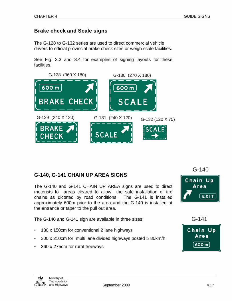
CHAPTER 4 GUIDE SIGNS
Ministry ofTransportationand Highways September 2000 4.17
Brake check and Scale signs The G-128 to G-132 series are used to direct commercial vehicle drivers to official provincial brake check sites or weigh scale facilities. See Fig. 3.3 and 3.4 for examples of signing layouts for thesefacilities.
G-140, G-141 CHAIN UP AREA SIGNS The G-140 and G-141 CHAIN UP AREA signs are used to directmotorists to areas cleared to allow the safe installation of tirechains as dictated by road conditions. The G-141 is installedapproximately 600m prior to the area and the G-140 is installed atthe entrance or taper to the pull out area. The G-140 and G-141 sign are available in three sizes: • 180 x 150cm for conventional 2 lane highways
• 300 x 210cm for multi lane divided highways posted ≥ 80km/h
• 360 x 275cm for rural freeways
G-140
G-141
G-128 (360 X 180) G-130 (270 X 180)
G-129 (240 X 120) G-131 (240 X 120) G-132 (120 X 75)
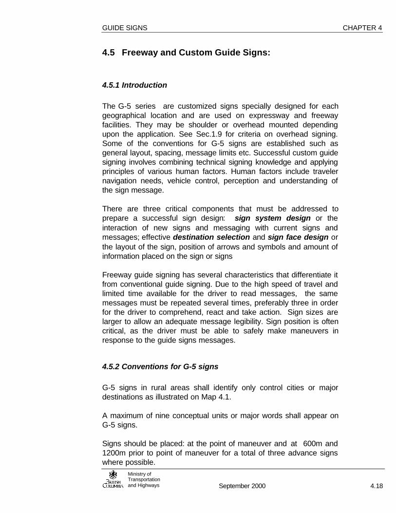
GUIDE SIGNS CHAPTER 4
Ministry ofTransportationand Highways September 2000 4.18
4.5 Freeway and Custom Guide Signs:
4.5.1 Introduction
The G-5 series are customized signs specially designed for eachgeographical location and are used on expressway and freewayfacilities. They may be shoulder or overhead mounted dependingupon the application. See Sec.1.9 for criteria on overhead signing.Some of the conventions for G-5 signs are established such asgeneral layout, spacing, message limits etc. Successful custom guidesigning involves combining technical signing knowledge and applyingprinciples of various human factors. Human factors include travelernavigation needs, vehicle control, perception and understanding ofthe sign message.
There are three critical components that must be addressed toprepare a successful sign design: sign system design or theinteraction of new signs and messaging with current signs andmessages; effective destination selection and sign face design orthe layout of the sign, position of arrows and symbols and amount ofinformation placed on the sign or signs
Freeway guide signing has several characteristics that differentiate itfrom conventional guide signing. Due to the high speed of travel andlimited time available for the driver to read messages, the samemessages must be repeated several times, preferably three in orderfor the driver to comprehend, react and take action. Sign sizes arelarger to allow an adequate message legibility. Sign position is oftencritical, as the driver must be able to safely make maneuvers inresponse to the guide signs messages.
4.5.2 Conventions for G-5 signs
G-5 signs in rural areas shall identify only control cities or majordestinations as illustrated on Map 4.1.
A maximum of nine conceptual units or major words shall appear onG-5 signs.
Signs should be placed: at the point of maneuver and at 600m and1200m prior to point of maneuver for a total of three advance signswhere possible.

CHAPTER 4 GUIDE SIGNS
Ministry ofTransportationand Highways September 2000 4.19
4.5.2 Cont’d
Ferry terminals should be identified on the sign within a colour codedpanel. Ferries are not consider a destination, only a means by whichthe motorist gets to their destination. Ferry terminals panels shouldbe used in conjunction with the city/town to which the route leads.Tsawwassen and Schwartz Bay terminals are identified on whitepanels with blue text. Duke Point is identified with black text on awhite panel. Horseshoe Bay and Departure Bay are identified withblue panels with white text.
Upward pointing arrows are used to indicate lane destination anddirection.
Minimum spacing between guide signs is 300m. Supplemental guidesigns may be spaced at a minimum of 200m. Maximum spacingshould not exceed 15 seconds of travel time.
Shoulder mounted signs should be oriented 5° away from the driverto reduce headlight glare.
Exit tabs or panels are always used on G-5 signs. On expresswaysor facilities where exit numbering is not used, the exit panel shallappear on the top left quadrant of the sign. On freeways a tab withthe text EXIT followed by the exit number shall be mounted on thetop right hand side above the sign in addition to the exit panel.
4.5.3 Guide Signing Theory
Signs are used to communicate information to the motorist through acombination of messaging ( letters, numerals, symbols diagrams orcombinations of these) sign shape and colour, and retroreflectivequalities. These criteria combined in certain ways and sizes directlyaffect the sign legibility.

GUIDE SIGNS CHAPTER 4
Ministry ofTransportationand Highways September 2000 4.20
Table 4.1 Street name Signs: Sizes and Materials
TYPE HEIGHT (mm)
LENGTHS (mm)
LETTERHEIGHT
(mm)
MATERIAL
G-7 150 450,600,750,900
75 Aluminum Flat Bar
G-7X 225 600,750,900,1200
125 Aluminum Flat Bar
G-7o 300 1200,1500,1800 150 Flat Sheet Aluminumor Plywood
G-7oX 400 1200, 1500,1800, 2100
230 Flat Sheet Aluminumor Plywood
G-8 400 600, 750,900 130 Flat Sheet Aluminumor Plywood
G-8D 400 900,1200 110 Plywood
Table 4.2 Criteria for Supplemental Signing for Major TrafficGenerators
Facility Criteria Rural Urban/Suburban
InstitutionalHospital
Max. distance from Highway:10km 5km
FairgroundsStadiums/Arenas
Publicly Owned(1)
Min Annual Attendance: 50,000 250,000Military Base Min. number of civilian &
military personnel on base: 2,000 2,000Zoos Publicly owned, non-profit,
Min attendance Numbers: 100,000 500,000
(1) Must have continuous year around activities. For periodic events temporarysigning may be used.
Note: The Regional Traffic Engineer shall determine if signs may be erected underthis criteria. Primary guide, warning and regulatory signs take precedent oversupplemental destinations therefore each eligible major traffic generator may notnecessarily be signed unless sufficient space exists on the roadway for such signs.Major traffic generators shall not be signed from urban freeways. Confirmatorysigns, including on municipal roads, should be in place before signs are erected onprovincial highways.
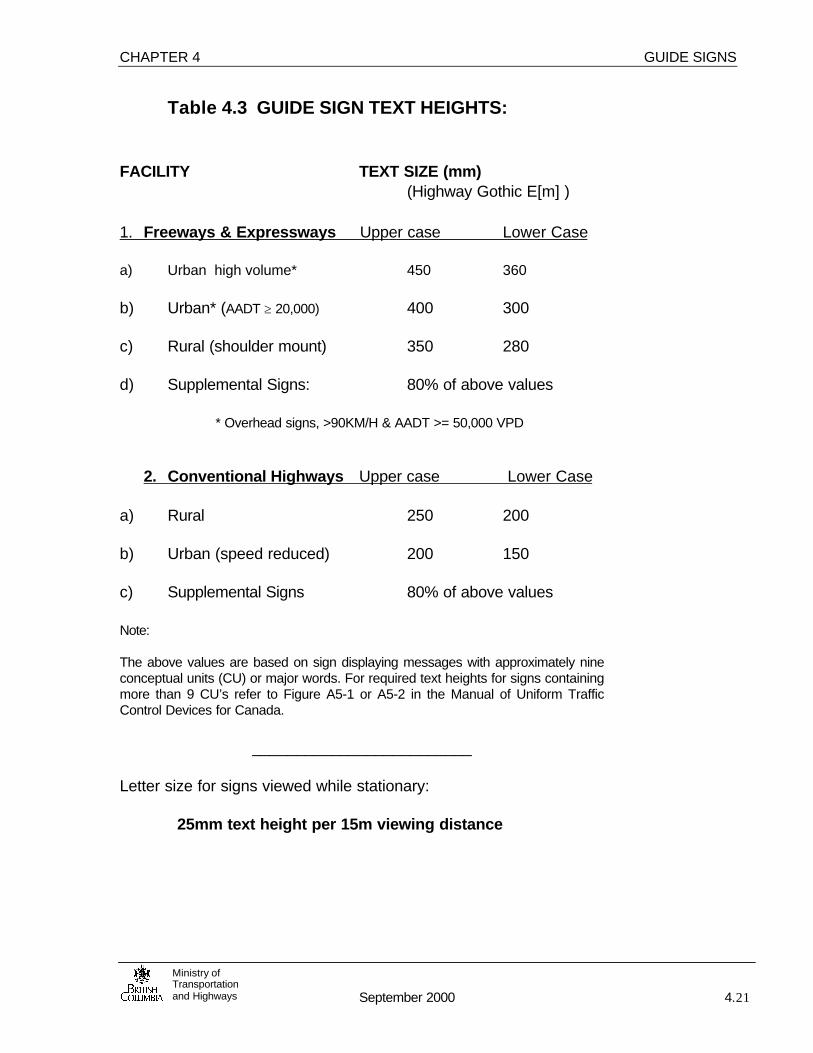
CHAPTER 4 GUIDE SIGNS
Ministry ofTransportationand Highways September 2000 4.21
Table 4.3 GUIDE SIGN TEXT HEIGHTS:
FACILITY TEXT SIZE (mm)(Highway Gothic E[m] )
1. Freeways & Expressways Upper case Lower Case
a) Urban high volume* 450 360
b) Urban* (AADT ≥ 20,000) 400 300 c) Rural (shoulder mount) 350 280 d) Supplemental Signs: 80% of above values * Overhead signs, >90KM/H & AADT >= 50,000 VPD
2. Conventional Highways Upper case Lower Case
a) Rural 250 200
b) Urban (speed reduced) 200 150
c) Supplemental Signs 80% of above values
Note:
The above values are based on sign displaying messages with approximately nineconceptual units (CU) or major words. For required text heights for signs containingmore than 9 CU’s refer to Figure A5-1 or A5-2 in the Manual of Uniform TrafficControl Devices for Canada.
_________________________
Letter size for signs viewed while stationary:
25mm text height per 15m viewing distance
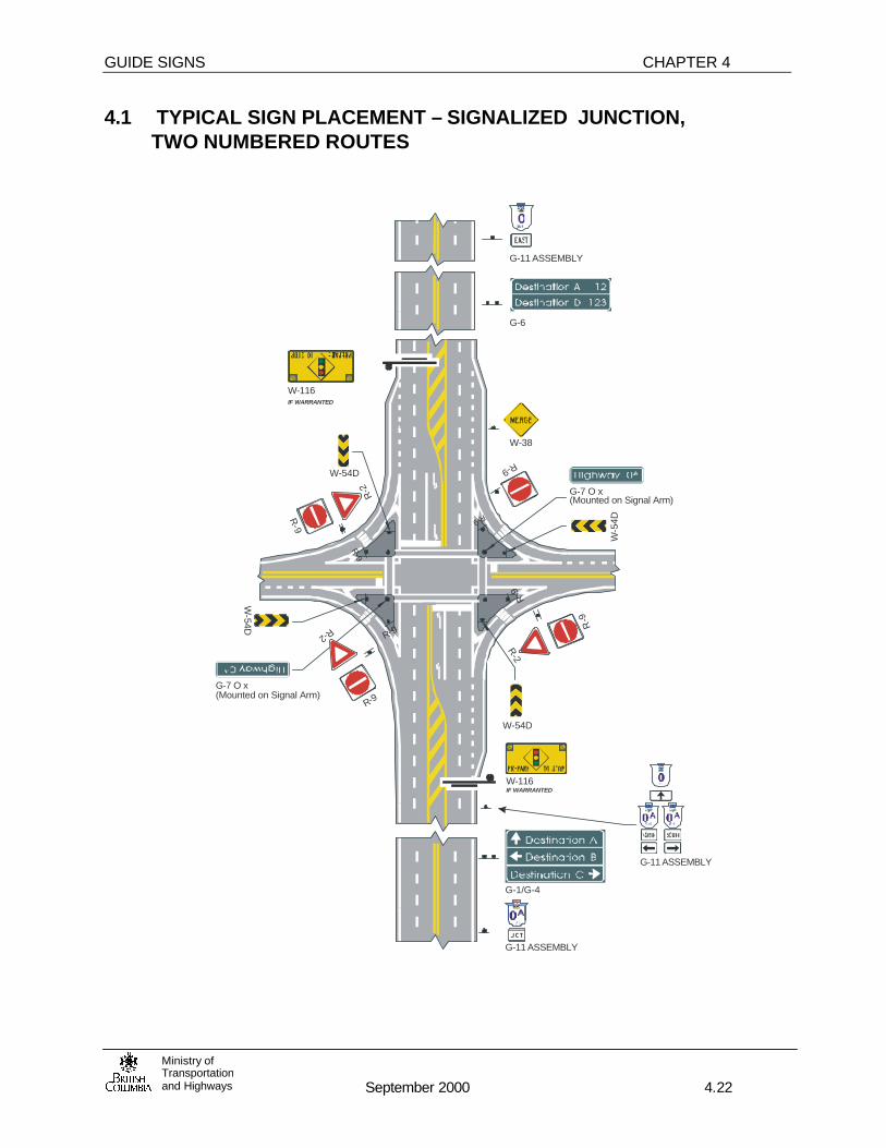
GUIDE SIGNS CHAPTER 4
Ministry ofTransportationand Highways September 2000 4.22
4.1 TYPICAL SIGN PLACEMENT – SIGNALIZED JUNCTION, TWO NUMBERED ROUTES
W-38
G-6
G-11 ASSEMBLY
G-11 ASSEMBLY
G-11 ASSEMBLY
G-7 O x(Mounted on Signal Arm)
W-5
4D
R-9
W-54D
R-2
R-9
W-54D
R-2
R-9
R-9
R-9
R-9
R-9
W-116
W-116
IF WARRANTED
IF WARRANTED
R-2
R-9
W-54D
G-7 O x(Mounted on Signal Arm)
G-1/G-4

CHAPTER 4 GUIDE SIGNS
Ministry ofTransportationand Highways September 2000 4.23
4.2 TYPICAL ROUTE MARKER PLACEMENT AT INTERSECTIONS
150m
Spacing per TABLE 1CONDITION B
100m15m
15m
60m75m

GUIDE SIGNS CHAPTER 4
Ministry ofTransportationand Highways September 2000 4.24
4.3 SAMPLE ROUTE MARKER PLACEMENTS
See Fig. 4.2 for guide sign placement and sign spacing.
A. Junction of Two Numbered Routes B. Route Turn
C. Route Diverge D. Route Merge 'T'

CHAPTER 4 GUIDE SIGNS
Ministry ofTransportationand Highways September 2000 4.25
B L A N K
(NO FIGURE 4.4)

GUIDE SIGNS CHAPTER 4
Ministry ofTransportationand Highways September 2000 4.26
4.5 CONVENTIONAL SINGLE LANE EXIT
600m
600m
Beginningof taper
2 signs prior to the exit sign is desirableSign spacing at 1200m and 600m is desirable, but may be revised to optimize sign visibility
To City A

CHAPTER 4 GUIDE SIGNS
Ministry ofTransportationand Highways September 2000 4.27
4.6 CONVENTIONAL RIGHT LANE MANDATORY EXIT
600m
600m

GUIDE SIGNS CHAPTER 4
Ministry ofTransportationand Highways September 2000 4.28
4.7 DUAL EXIT, TAPER TERMINAL
600m
600m

CHAPTER 4 GUIDE SIGNS
Ministry ofTransportationand Highways September 2000 4.29
4.8 DUAL EXIT, RIGHT LANE MANDATORY EXIT
or:
600m
600m

GUIDE SIGNS CHAPTER 4
Ministry ofTransportationand Highways September 2000 4.30
4.8 CONVENTIONAL INTERCHANGE, SEQUENTIAL EXITS
1200
m
To City BEastbound

CHAPTER 4 GUIDE SIGNS
Ministry ofTransportationand Highways September 2000 4.31
4.10 CONVENTIONAL INTERCHANGE, SINGLE EXIT
600m
600m
Cross RoadWestbound
Cross RoadEastbound

GUIDE SIGNS CHAPTER 4
Ministry ofTransportationand Highways September 2000 4.32
4.11 CLOSELY SPACED ENTRANCE-EXIT RAMPS
X00
m
200m

CHAPTER 4 GUIDE SIGNS
Ministry ofTransportationand Highways September 2000 4.33
4.12 MAJOR DIVERGE
600m
600m
At start of Diversion
To City AVia Route 0
To City BVia Route 0
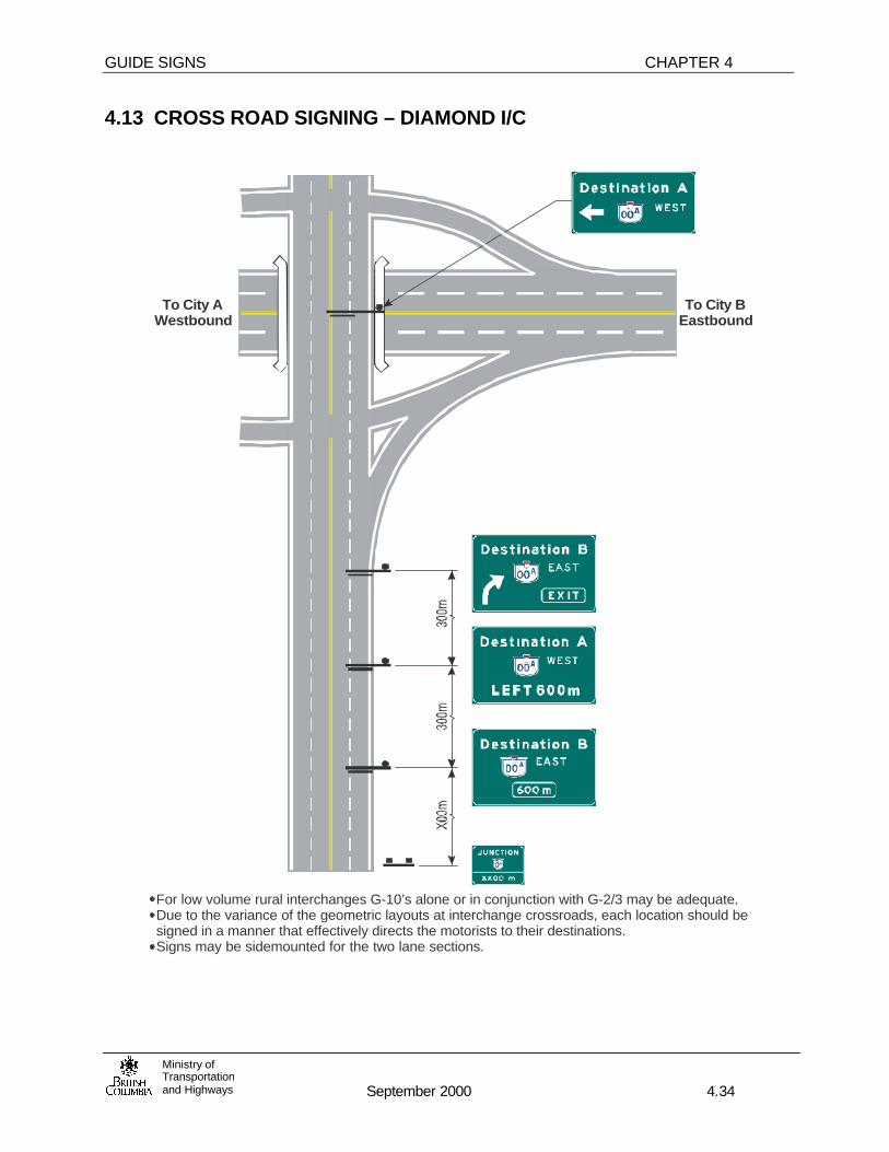
GUIDE SIGNS CHAPTER 4
Ministry ofTransportationand Highways September 2000 4.34
4.13 CROSS ROAD SIGNING – DIAMOND I/C
For low volume rural interchanges G-10’s alone or in conjunction with G-2/3 may be adequate.Due to the variance of the geometric layouts at interchange crossroads, each location should besigned in a manner that effectively directs the motorists to their destinations.Signs may be sidemounted for the two lane sections.
To City AWestbound
To City BEastbound

CHAPTER 4 GUIDE SIGNS
Ministry ofTransportationand Highways September 2000 4.35
4.14 CROSS ROAD SIGNING – CONVENTIONAL I/C
To City AWestbound
To City BEastbound

Vancouver
Seattle
Edmonton
Whitehorse
Calgary
Squamish
VictoriaPort Renfrew
Sooke
NanaimoParksville
Courtenay
Campbell River
Port Hardy
Hope
Princeton
Merritt
Penticton
Kelowna
Vernon
Revelstoke
Golden
Kamloops
CacheCreek
100 Mile House
WilliamsLake
Quesnel
PrinceGeorge
Hudson'sHope
Vanderhoof
Mackenzie TumblerRidge
DawsonCreek
FortSt. John
PrinceRupert
Terrace
Masset
Smithers
Houston
BurnsLake
FortSt. James
DeaseLake
FortNelson
Bella Coola
Osoyoos
Atlin
Spirit River
Grande Prairie
Lethbridge
Jasper
Banff
Mica Creek
Kitimat
Stewart
PowellRiver
Port AlberniTofino
Whistler
Salmon Arm
16
16
16
2716
16
16
97A
97C
3/95
37
37
37 97
97
9797
9739
97
9720
23
5
1
6
6
6
3B3
3
5A
5A
5
5
1
1
17
1
14
4
19
19
101
12
99
8
97
3
3A
93/95
935
24
29
77
93
3/93
37
Cranbrook
CrestonNelson
Fernie
USAUSAUSA
USA USA
KootenayBay
Crowsnest Pass
Nakusp
Balfour
Elkford
Kimberley
Invermere
Salmo
Trail
GrandForks
NewDenver
Kaslo
3/95
23
6
3
3
3A
93/95
93
3/93
INSET
3B
Castlegar
6
SeeInset
Ministry of Transportationand Highways
LEGEND
1805-2-1 (00/19)
MAJOR OR END DESTINATION
CONTROL DESTINATIONS
CONTROL DESTINATIONS AND MAJOR DESTINATIONS FOR GUIDE SIGNS IN BRITISH COLUMBIA

CHAPTER 5 SCHOOL & PEDESTRIAN SIGNS
September 2000 5.1Ministry ofTransportationand Highways
Note: Warrants and application criteria for pedestrian crossingfacilities are detailed in the “Pedestrian Crossing Manual for BritishColumbia” or current equivalent document.
SP-1 SCHOOL AREA SIGN
The SP-1 SCHOOL AREA sign is used to warn motorists that theyare in the vicinity of a school and children may be walking along orcrossing the roadway. It may also be used in place of an SP-16sign where there are both a school crosswalk and children walkingalong the road.
In cases where a reduction from the posted speed limit is required,SP-7 or SP-8 speed zone tabs may be used in conjunction withSP-1 signs. Refer to the SP-7 or SP-8 sign descriptions for moreinformation regarding their use.
A SP-17 NO PASSING tab shall be erected below SP-1 signswhere traffic approaches an established crosswalk on a two laneroadway. If an SP-7 or 8 tab is also necessary, the SP-17 tab shallbe mounted below a secondary SP-1, and erected a suitabledistance in advance of the primary assembly.
The SP-1 should be installed in advance of school crosswalks perthe Pedestrian Crossing Control Manual or per Table 1, Condition“B” prior to the boundary of school grounds.
Refer to Fig. 5.2 for sample sign placement and layout.
The SP-1 oversize sign may be used wherever the speed limit is 70km/h or higher, or where additional emphasis is required.
This sign will be converted to black on fluorescent yellow-greencolours to conform to the M.U.T.C.D. for Canada. Contact theTraffic & Electrical Section for details.
SP-2 PEDESTRIAN CROSSWALK AHEAD
The SP-2 PEDESTRIAN CROSSWALK AHEAD sign warnsmotorists that they are approaching a pedestrian crosswalk atlocations with limited sight visibility to the crosswalk or areas wherepedestrians may be walking along the road.
The pedestrian symbol should be oriented to face towards thecentre of the roadway.

SCHOOL & PEDESTRIAN CHAPTER 5
September 2000 5.2Ministry ofTransportationand Highways
The SP-2 should be installed per the Pedestrian Crossing ControlManual.
SP-3 PLAYGROUND AHEAD
The SP-3 PLAYGROUND AHEAD sign warns motorists of a nearbypublic playground, where the presence of children, on or near theroadway, could create a hazard to the motorist.
In special cases, where speed zone is desirable a SP-7 30 km/htab may be used in conjunction with an SP-3 sign. Refer to the SP-7 sign descriptions for more information regarding theestablishment of a 30 km/h playground speed zone.
A SP-17 NO PASSING tab should be erected below SP-3 signswhere the traffic approaches an established crosswalk on a two-lane roadway. If a SP-7 tab is also required, the SP-17 tab shall bemounted below a secondary SP-3 and erected a suitable distancein advance of the primary assembly.
Refer to the SP-17 sign description for more information regardingits use.
The sign should be installed per the Pedestrian Crossing ControlManual.
SP- 4 SCHOOL CROSSWALK
The SP-4L/R SCHOOL CROSSWALK signs indicates to motoriststhe location of school crosswalks.
School crosswalks should be installed in accordance to thePedestrian Crossing Control Manual, in consultation with schooland municipal authorities, as required.
Crosswalks should only be installed if they meet the appropriatewarrant criteria.
A marked crosswalk shall always be indicated both by pavementmarkings and signs or traffic signals. At raised rightchannelizations, SP-4 signs are not required.
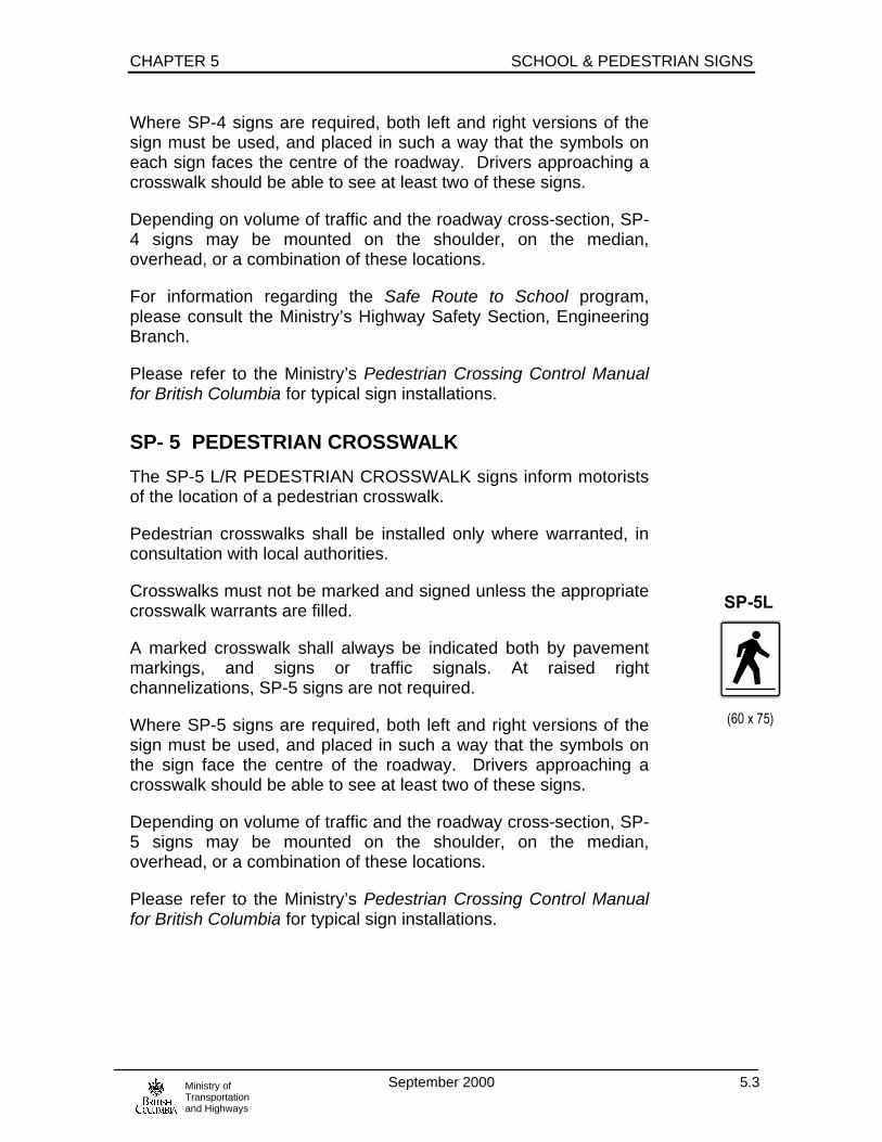
CHAPTER 5 SCHOOL & PEDESTRIAN SIGNS
September 2000 5.3Ministry ofTransportationand Highways
Where SP-4 signs are required, both left and right versions of thesign must be used, and placed in such a way that the symbols oneach sign faces the centre of the roadway. Drivers approaching acrosswalk should be able to see at least two of these signs.
Depending on volume of traffic and the roadway cross-section, SP-4 signs may be mounted on the shoulder, on the median,overhead, or a combination of these locations.
For information regarding the Safe Route to School program,please consult the Ministry’s Highway Safety Section, EngineeringBranch.
Please refer to the Ministry’s Pedestrian Crossing Control Manualfor British Columbia for typical sign installations.
SP- 5 PEDESTRIAN CROSSWALK
The SP-5 L/R PEDESTRIAN CROSSWALK signs inform motoristsof the location of a pedestrian crosswalk.
Pedestrian crosswalks shall be installed only where warranted, inconsultation with local authorities.
Crosswalks must not be marked and signed unless the appropriatecrosswalk warrants are filled.
A marked crosswalk shall always be indicated both by pavementmarkings, and signs or traffic signals. At raised rightchannelizations, SP-5 signs are not required.
Where SP-5 signs are required, both left and right versions of thesign must be used, and placed in such a way that the symbols onthe sign face the centre of the roadway. Drivers approaching acrosswalk should be able to see at least two of these signs.
Depending on volume of traffic and the roadway cross-section, SP-5 signs may be mounted on the shoulder, on the median,overhead, or a combination of these locations.
Please refer to the Ministry’s Pedestrian Crossing Control Manualfor British Columbia for typical sign installations.

SCHOOL & PEDESTRIAN CHAPTER 5
September 2000 5.4Ministry ofTransportationand Highways
SP-7 SPEED ZONE TABS FOR SCHOOL &PLAYGROUND AREAS
The SP-7 30 km/h tab is used to establish a speed zone forelementary schools or playgrounds and is used in conjunction witha SP-1 or SP-3 sign. When SP-7 tabs are used, a 30 km/h schoolspeed zone is established, for the period between 0800h and1700h on school days. When used with an SP-3 sign, the SP-7establishes a similar playground speed zone between dawn anddusk.
The Senior Traffic Engineer’s approval must be obtained beforeestablishing these zones. The zones are used only in very specialcases, and are not allowed on numbered routes or arterialhighways. The ends of school and playground speed zones shouldbe marked by reconfirming the primary speed zone by installing aR-4 sign within approximately 100m of the end of the school speedzone.
If used , the SP-7 tab shall be mounted below the SP-1 or SP-3sign.
SP- 8 50km/h WHEN CHILDREN ON HIGHWAY SIGN
The SP-8 50 km/h WHEN CHILDREN ON HIGHWAY tab signinforms motorists that the maximum allowable speed of travel,when children are present on the roadway, is 50 km/h.
When SP-8 tabs are used with SP-1 signs on highways which areconsidered routes to school when the speed limit is 60 km/h orhigher. The 50 km/h speed zone is in effect whenever children areon any part of the traveled roadway, between 0800h and 1700h onschool days.
The end of this zone should be marked by reconfirming the primaryspeed zone, using a R-4 sign, within approximately 100m of theend of the area where this restriction takes place.
In special cases, the speed limit displayed on SP-8 signs may belowered or increased to accommodate certain situations, but onlywith the prior approval of the Senior Traffic Engineer.
If used, the SP-8 tabs shall be mounted below the SP-1 signs.

CHAPTER 5 SCHOOL & PEDESTRIAN SIGNS
September 2000 5.5Ministry ofTransportationand Highways
SP- 9 NO PEDESTRIAN CROSSING
The SP-9 NO PEDESTRIAN CROSSING sign informs pedestriansthat crossing the roadway at the signed location is prohibited.
This sign should be used at locations where pedestrians are knownto cross a roadway at a point deemed unsafe or improper.
The SP-9 should be installed to face the sidewalk, with the bottomof the sign 1.0 m above the pavement. This sign should bepositioned so as to be highly visible to pedestrians who may betempted to cross where it is unsafe to do so.
SP- 10 PUSH BUTTON FOR WALK SIGNAL
The SP-10 L/R/D PUSH BUTTON FOR WALK SIGNAL signinforms pedestrians that they must use the marked button in orderto activate the pedestrian crossing signal.
The SP-10 should be used at locations that have pedestrianactuated traffic control signals.
Where required, SP-10 signs shall be mounted 15 cm above thepush button. The appropriate version of the sign with the arrowand pedestrian symbols pointing in the direction of the crossingshould be used for each location.
SP- 11 DO NOT PASS SCHOOL BUS WHEN LIGHTSFLASHING
The SP-11 DO NOT PASS WHEN LIGHTS FLASHING signinforms motorists that passing a school bus with flashing red lightsis prohibited.
This sign was installed at vehicle entry points to the province, onthe outskirts of communities and at random locations along schoolbus routes. There may be unusual situations where the use ofadditional SP-11 signs is necessary, but this sign should be limitedto replacement of existing signs only.
60 x 60

SCHOOL & PEDESTRIAN CHAPTER 5
September 2000 5.6Ministry ofTransportationand Highways
SP- 12 NO FISHING OR LOITERING ON BRIDGE
The SP-12 NO FISHING OR LOITERING ON BRIDGE signindicates that fishing or unnecessary lingering on the bridge mayconstitute a hazard to themselves and to passing motorists andtherefore is prohibited.
This sign shall be erected on the bridge structure, and oriented soas to be easily observed by pedestrians.
SP- 13 WALK ON LEFT FACING TRAFFIC
The SP-13 WALK ON LEFT FACING TRAFFIC sign informspedestrians that it is safer to walk along the roadway shoulderagainst the direction of traffic.
The SP-13 sign is used to encourage safer pedestrian roadwayhabits in locations where there is an absence of pedestrianpathways or sidewalks. It is particularly useful at the edge of built-up districts where sidewalks are discontinued.
Where required, SP-13 signs should be installed on the right handside of the roadway in such a way as to be easily seen bypedestrians.
SP- 16 SCHOOL CROSSWALK AHEAD
The SP-16 SCHOOL CROSSWALK AHEAD signs warns motoriststhat they are approaching a school crosswalk.
The SP-16 sign shall be installed on the right side of the roadwaywith the symbol oriented to face across the roadway.
For more information regarding the SP-16 sign, please refer to thePedestrian Crossing Control Manual for British Columbia.
This sign will be converted to fluorescent yellow-green backgroundcolour to conform to the M.U.T.C.D. for Canada. Contact the Traffic& Electrical Section for details.
SP- 17 NO PASSING TAB
The SP-17 NO PASSING tab sign informs motorists that passing isprohibited on the roadway through the school zone.
The SP-17 may be used below SP-1 and SP-3 (or below the SP-7/8 tab if used) signs on 2 lane roadways if pavement markingsrestrict passing.

CHAPTER 5 SCHOOL & PEDESTRIAN SIGNS
September 2000 5.7Ministry ofTransportationand Highways
SP- 18 PEDESTRIANS USE SIGNAL
The SP-18 PEDESTRIAN USE SIGNAL sign directs pedestrians touse the signalized crosswalk to cross the road.
The SP-18 sign is used where crosswalks have been removed, andpedestrian crossing is only permitted at the signalized intersections.
If a handrail exists at the location, the SP-18 sign shall be mountedon the rail.
SP- 19 SCHOOL BUS TURN AHEAD
The SP-19 SCHOOL BUS TURN AHEAD sign warns motorists ofthe presence of a designated school bus turn-around facility.
This sign should be installed per Table 1 Condition A, AppendixA-1.
Use of this sign requires Senior Traffic Engineer approval.
SP- 20 SCHOOL BUS STOP AHEAD
The SP-20 SCHOOL BUS STOP AHEAD warns motorists of thepresence of school bus stops, and the possibility of children on theroad.
This sign shall be used at unanticipated or poorly located schoolbus stops, where potential hazards may exist. Relocation of suchbus stops to a better location should be considered, but this mustbe weighed against the fact that children may be required to walkfarther along the roadway to reach the relocated bus stop.
This sign should be installed per Table 1 Condition A, AppendixA-1.
Use of this sign requires Senior Traffic Engineer approval.

SCHOOL & PEDESTRIAN CHAPTER 5
September 2000 5.8Ministry ofTransportationand Highways
R-1
R-1
R-1
R-1
G-7 G-7
XYZ RD. XYZ RD.
Figure 5.1 Crosswalk SigningSE
E D
IMEN
SIO
N A
SEE
DIM
ENSI
ON
A
SEE
DIM
ENSI
ON
A
SEE
DIM
ENSI
ON
A
NO
PAS
SIN
G Z
ON
E
NO
PAS
SIN
G Z
ON
E
NO
PAS
SIN
G Z
ON
E
NO
PAS
SIN
G Z
ON
E
1.0 m 1.0 m
NO
STO
PPIN
G
NO
STO
PPIN
G
30 m
30 m
SP-005R SP-005R
SP-005R SP-005R
SP-005L SP-005L
SP-002 SP-002
SP-002 SP-002
G-7 G-7
P-8L
P-8L
P-8L
P-8L
Notes:
1. See Figure 7.45 for crosswalk marking
2. Refer to the current pedestrian crossing manual for warrants and other crossing types

CHAPTER 5 SCHOOL & PEDESTRIAN SIGNS
September 2000 5.9Ministry ofTransportationand Highways
R-1
R-1
Figure 5.2 School Area and Crosswalk Signing
SP-001
SP-001
P-8L
P-8L
5 m
NO
STO
PPIN
G
NO
STO
PPIN
G
30 m
30 m
5 m
NO
LAN
E C
HAN
GIN
G (3
0 m
MIN
.)
NO
LAN
E C
HAN
GIN
G (3
0 m
MIN
.)
MOUNTED OVERHEAD
SP-004L
SP-004R
MOUNTEDOVERHEAD
G-7
G-7
XYZ RD.
XYZRD.1 m
SP-004R
SP-004L
Notes:
1. See Figure 7.46 for school crossing pavement markings
2. Refer to the current pedestrian crossing manual forwarrants and other crossing types

CHAPTER 6 INFORMATION SIGNS
September 2000 6.1Ministry ofTransportationand Highways
I-3
75 x 30
I-6
80 x 60
I-3 CREEK, RIVER & LAKE SIGNS
The 1-3 CREEK, RIVER or LAKE sign should beused to identify major creeks and rivers that flowunder or near a numbered highway and all lakes thatare visible from the highway.
The I-3 signs may be installed on the bridge structureor in advance of the bridge or culvert as fieldconditions permit.
When used to identify lakes, the I-3 sign should beinstalled on its own post on the shoulder at pointswhere the lake is visible and may be repeated every 5to 10km where the highway follows the shoreline of alarge lake.
I-6 HISTORIC SITE SIGN
The I-6 Historical site sign may be used to identifyhistoric sites established and maintained by theFederal Government, the Heritage Branch of theMinistry of Small Business, Tourism and Culture orany other recognized non-profit historical agency orsociety. Signs within the site are supplied andinstalled by the agency operating site or may beunder permit if within the highway right of way.
The I-6 should be placed approximately 400m inadvance of the access to the site.
I-7 STOP OF INTEREST SIGN
The I-7 STOP OF INTEREST sign is used in advanceof a pullout or viewpoint that has is a stop of interestto the traveling public.
Typically these sites are geographical orenvironmental in nature and have permanent raisedprofile metal signs within the site The signs areinstalled and maintained by the agency or society thatidentified the entity of interest. The I-7 sign should beinstalled approximately 400m in advance of theaccess to the pullout.
I-7
60 x 80

INFORMATION SIGNS CHAPTER 6
September 2000 6.2Ministry ofTransportationand Highways
I-8, I-9 VIEWPOINT and ENTRANCE SIGN
The I-8 VIEWPOINT sign should be installedapproximately 400m prior to the entrance to anestablished viewpoint. If the site is designated as a stopof interest the I-7 sign should be used instead of the I-8sign.
The I-9 VIEWPOINT ENTRANCE sign should only beused when the entrance to the site is not clearly visiblyto the motorist.
I-10 / I-11 REST AREA SIGNS
I-10 and I-11 REST AREA signs are used to identifyrest areas established by MoTH.
The I-11 should be installed approximately 400m priorto the access to the rest area and the I-10 should beinstalled just prior to the entrance.
See also I-108 REST AREA INFORMATION sign.
I-10
I-11
90 X 90
90 X 120
I-8
60 x 80
I-9
90 x 45
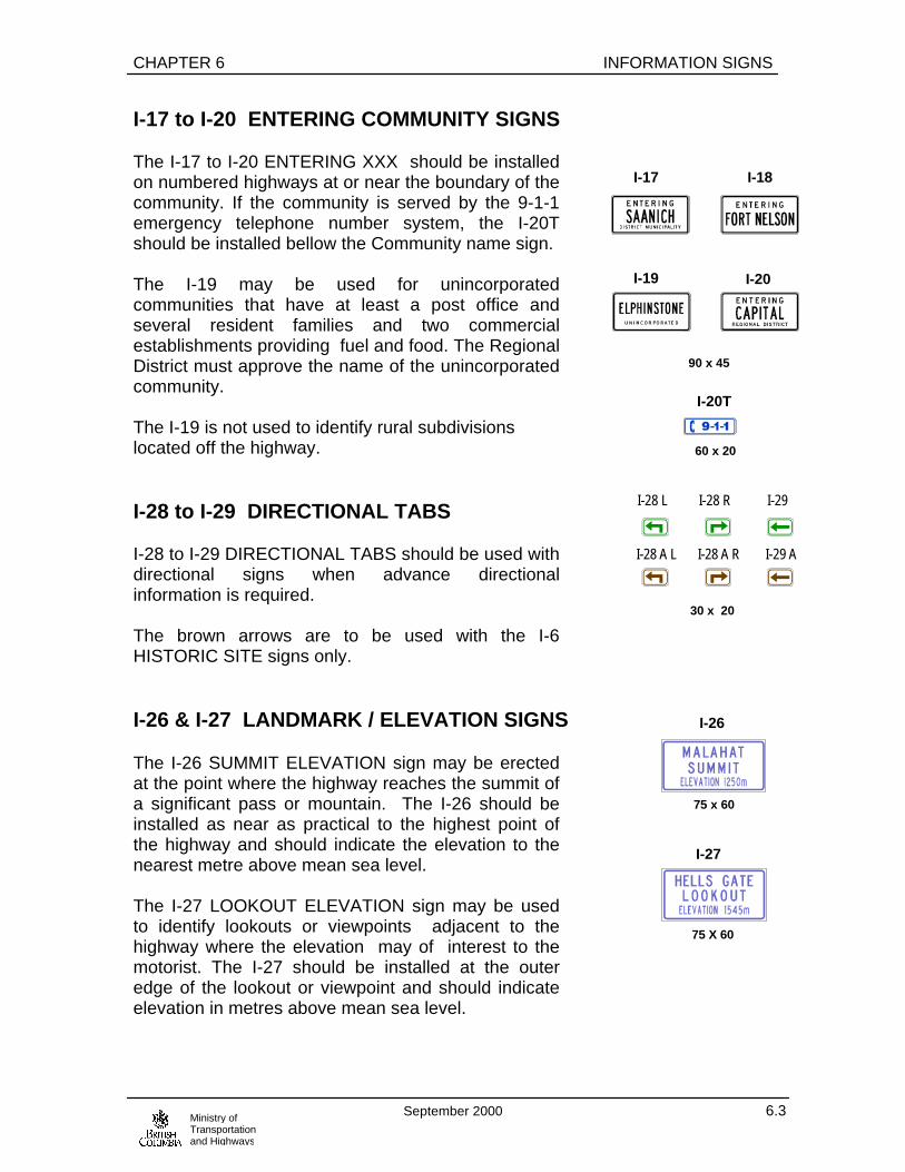
CHAPTER 6 INFORMATION SIGNS
September 2000 6.3Ministry ofTransportationand Highways
I-17 to I-20 ENTERING COMMUNITY SIGNS
The I-17 to I-20 ENTERING XXX should be installedon numbered highways at or near the boundary of thecommunity. If the community is served by the 9-1-1emergency telephone number system, the I-20Tshould be installed bellow the Community name sign.
The I-19 may be used for unincorporatedcommunities that have at least a post office andseveral resident families and two commercialestablishments providing fuel and food. The RegionalDistrict must approve the name of the unincorporatedcommunity.
The I-19 is not used to identify rural subdivisionslocated off the highway.
I-28 to I-29 DIRECTIONAL TABS
I-28 to I-29 DIRECTIONAL TABS should be used withdirectional signs when advance directionalinformation is required.
The brown arrows are to be used with the I-6HISTORIC SITE signs only.
I-26 & I-27 LANDMARK / ELEVATION SIGNS
The I-26 SUMMIT ELEVATION sign may be erectedat the point where the highway reaches the summit ofa significant pass or mountain. The I-26 should beinstalled as near as practical to the highest point ofthe highway and should indicate the elevation to thenearest metre above mean sea level.
The I-27 LOOKOUT ELEVATION sign may be usedto identify lookouts or viewpoints adjacent to thehighway where the elevation may of interest to themotorist. The I-27 should be installed at the outeredge of the lookout or viewpoint and should indicateelevation in metres above mean sea level.
I-28 L
I-28 A L
I-28 R
I-28 A R
I-29
I-29 A
30 x 20
I-17 I-18
I-19 I-20
90 x 45
I-20T
60 x 20
I-26
75 x 60
I-27
75 X 60
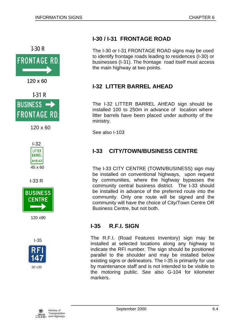
INFORMATION SIGNS CHAPTER 6
September 2000 6.4Ministry ofTransportationand Highways
I-30 / I-31 FRONTAGE ROAD
The I-30 or I-31 FRONTAGE ROAD signs may be usedto identify frontage roads leading to residences (I-30) orbusinesses (I-31). The frontage road itself must accessthe main highway at two points.
I-32 LITTER BARREL AHEAD
The I-32 LITTER BARREL AHEAD sign should beinstalled 100 to 250m in advance of location wherelitter barrels have been placed under authority of theministry.
See also I-103
I-33 CITY/TOWN/BUSINESS CENTRE
The I-33 CITY CENTRE (TOWN/BUSINESS) sign maybe installed on conventional highways, upon requestby communities, where the highway bypasses thecommunity central business district. The I-33 shouldbe installed in advance of the preferred route into thecommunity. Only one route will be signed and thecommunity will have the choice of City/Town Centre ORBusiness Centre, but not both.
I-35 R.F.I. SIGN
The R.F.I. (Road Features Inventory) sign may beinstalled at selected locations along any highway toindicate the RFI number. The sign should be positionedparallel to the shoulder and may be installed belowexisting signs or delineators. The I-35 is primarily for useby maintenance staff and is not intended to be visible tothe motoring public. See also G-104 for kilometermarkers.
I-31 R
120 x 60120 x 60
120 x 60
I-30 R
I-32
45 x 60
I-33 R
120 x90
I-35
30 x30

CHAPTER 6 INFORMATION SIGNS
September 2000 6.5Ministry ofTransportationand Highways
I-43 SLOW VEHICLES USE PULLOUT500mI-45 PULLOUT
The I-43 and I-45 “PULLOUT” signs should be usedto direct slow moving vehicles into pull-out lane (seeFig 7.36 for typical layout)
I-63 PASSING LANE 2km AHEAD
The I-63 PASSING LANE 2km AHEAD sign shall beerected 2km in advance of a passing lane, which isprovided on rural highways to facilitate passingvehicles travelling in the same direction.
If it is not practical to install this sign 2km in advanceof the passing lane, the position may be adjusted andthe distance on the sign adjusted accordingly.
The new version of the I-63 sign will be phased in onBC highways through attrition. Upon depletion of thesign shop’s stock, this sign will be supplied inaccordance to the TAC ID-23 version.
I-64 FRUIT STAND(S) I-64T
I-170 PRODUCE STAND(S)
The I-64 FRUIT STAND or I-170 PRODUCE STANDsigns may be used on conventional highways inadvance of an eligible fruit or produce stand or standsor in advance of sideroads where eligible stands arelocated. Fruit or produce stands should be permanentstructures, legally erected, meeting zoningregulations, with adequate parking area. Operatorsshould have a business license sell and only locallygrown products.
I-43
120 x 60
I-63
60 x 75
I-170 SI-170
I-64 I-64 S
60 x 60
I-063
I-63 T
90 x90
90 x60
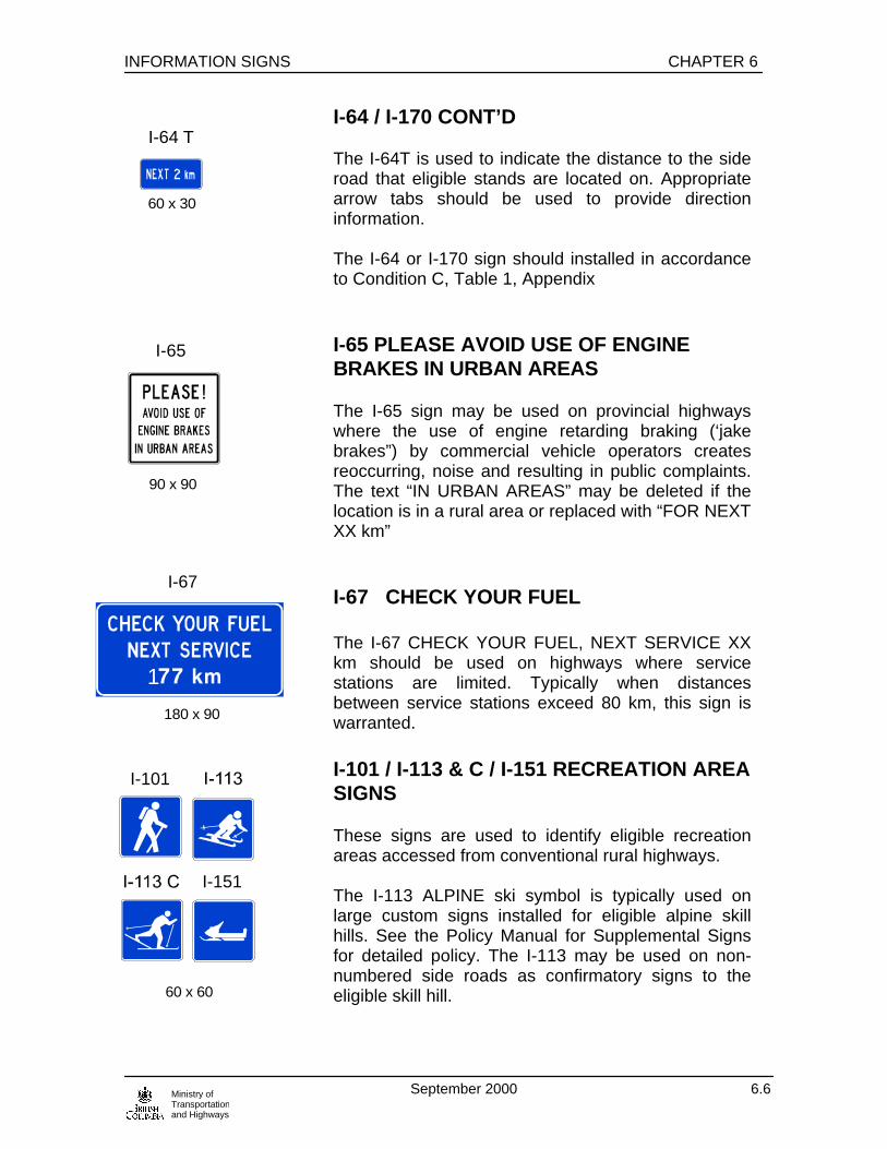
INFORMATION SIGNS CHAPTER 6
September 2000 6.6Ministry ofTransportationand Highways
I-64 / I-170 CONT’D
The I-64T is used to indicate the distance to the sideroad that eligible stands are located on. Appropriatearrow tabs should be used to provide directioninformation.
The I-64 or I-170 sign should installed in accordanceto Condition C, Table 1, Appendix
I-65 PLEASE AVOID USE OF ENGINEBRAKES IN URBAN AREAS
The I-65 sign may be used on provincial highwayswhere the use of engine retarding braking (‘jakebrakes”) by commercial vehicle operators createsreoccurring, noise and resulting in public complaints.The text “IN URBAN AREAS” may be deleted if thelocation is in a rural area or replaced with “FOR NEXTXX km”
I-67 CHECK YOUR FUEL
The I-67 CHECK YOUR FUEL, NEXT SERVICE XXkm should be used on highways where servicestations are limited. Typically when distancesbetween service stations exceed 80 km, this sign iswarranted.
I-101 / I-113 & C / I-151 RECREATION AREASIGNS
These signs are used to identify eligible recreationareas accessed from conventional rural highways.
The I-113 ALPINE ski symbol is typically used onlarge custom signs installed for eligible alpine skillhills. See the Policy Manual for Supplemental Signsfor detailed policy. The I-113 may be used on non-numbered side roads as confirmatory signs to theeligible skill hill.
I-64 T
60 x 30
I-65
90 x 90
I-67
180 x 90
1
I-101
I-151
60 x 60

CHAPTER 6 INFORMATION SIGNS
September 2000 6.7Ministry ofTransportationand Highways
RECREATION AREA SIGNS, CONT’D
The I-113C/I151/I-101 sign may be installed on anyrural conventional highway to indicate an eligiblecross country ski, snowmobile or hiking area. Theparticular area should have adequate off-site parking and marked and groomed or maintained trails. Thesesigns are not to be used to mark trails that cross oruse provincial highways rights of way.
I-103 LITTER BARREL
The I-103 LITTER BARREL sign should be used nearor on litter barrels installed under the authority of theministry in rest areas.
I-108 REST AREA IDENTIFICATION SIGN
The I-108 REST AREA sign should be used inministry maintained rest areas to identify the name ofthe rest area and the local district highways office.
I-110 SHORE ACCESS
The I-110 SHORE ACCESS sign may be used onrural, subdivision roads (non-numbered highways) toindicate access to oceans, lakes or rivers.
__________________________________________

INFORMATION SIGNS CHAPTER 6
September 2000 6.8Ministry ofTransportationand Highways
I-136 / I-137 / I-140 VISITOR INFORMATIONSIGNS
The visitor information centres are approved andadministered by the Manager, Visitor Services,Tourism B.C. Contact the Senior Traffic Engineer forthe current approval procedure.
The I-136 signs are used to inform motorists of “Level1” (Full Status Visitor Info Centre) or “Level 2”(Associate Visitor Info Centre).
I-136 signs are installed typically 2km prior to theaccess or turn-off to the centre, followed by a sign400m prior to the main access. Variation on thedistance and arrows styles are permitted to suitspecific site requirements.
I-136X (120 x120cm) signs should be used on multi-lane high speed (>70km/h) facilities.
The I-137TA, I-137TC, I-137TR VISITORINFORMATION signs are used to inform motorists ofTourism B.C. visitor centres that also provide area,community or regional information at the samelocation.
The I-137A, I-137C, I-137R VISITOR INFORMATIONsigns are used to inform motorists of visitor centressponsored by local or regional tourism agenciesoffering area, community or regional information only.
Any of the I-137 sign series are typically installed400m in advance of the access or side road to theinfo centre with the appropriate I-138L/R tab.
On freeway facilities, a customized sign will befabricated and installed as a “tab” below an existingguide sign, usually the 1200m or on a separatestructure approximately 2km in advance of the exit tothe centre. Continuity signs should be provided fromthe exit ramp to the centre as required.
The I-140 sign is used for “Level 3” Tourist/VisitorInformation Booths.
75 x75
I-137 TA I-137 TC I-137 TR
75 x 120
I-137 A I-137 C I-137 R
75 x 75
I-138 L I-138 R
75 x 30
I-140
75 x 75

CHAPTER 6 INFORMATION SIGNS
September 2000 6.9Ministry ofTransportationand Highways
I-157 SPEED ZONE AREA
The I-157 Entering or Leaving signs should be usedwhere blanket speed zones are in effect (see R-4warrant Chapter 2 for details on blanket zones)
I-167 FIRE SIGNAL
The I-167 FIRE SIGNAL should be installed inadvance of firehalls per Fig. 7.43 of Chapter 7.
Note the sign is supplied with a cutout for the signalhead.
I-168 / I-169 WILDLIFE VIEWING AREA
The I-168 WILDLIFE VIEWING ARE and I-169CONFIRMATORY signs may be used to identifydesignated viewing areas established by the Ministryof Environment, Lands & Parks or other recognizedagency.
The Ministry of Transportation and Highways willinstall the I-169 sign on highways in advance of theaccess or turnoff to the site, and the I-169confirmatory signs are installed by others underpermit from the highways district office.
The I-168/I-169 will not be installed on freeways.
I-171 PLEASE LET BUSES ENTER
The I-171 sign may be used where public transit busesexperience difficulty in entering main stream trafficunder a merge condition.
I-157 E I-157 L
60 x 45
I-168
I-167 R
75 x 120
90 x 135
I-169
60 x 60
60 x 75

INFORMATION SIGNS CHAPTER 6
September 2000 6.10Ministry ofTransportationand Highways
I-174 WINE ROUTE
Wine Route signs may be installed on provincialhighways that are designated a “wine route” by theWine Institute of BC and the Ministry of Transportationand Highways.
For details on this sign policy see the Policy Manualfor Supplemental Signs.
I-175 BRAKE CHECK ADVISORY
The I-175 BRAKE CHECK SIGN forms part of thesigning requirements for designated brake checkareas. Refer to Figures 3.3 and 3.4 of Chapter 3 forsign placement.
I-174
45 x 60
240 x 190

CHAPTER 6 INFORMATION SIGNS
September 2000 6.11Ministry ofTransportationand Highways
I-177 B.C. GROWN™ SIGN
The I-177 B.C.Grown™ Sign may be used on ruralconventional highways or expressways to identifyeligible direct farm market operations located up to7km from the highway.
If there are two or more eligible farm operations thenthe I-177T “X FARMS” tab must be used.
The I-178 arrow/”CLOSED” tab shall also be usedbelow the I-177T. The farm operator is responsible forensuring the “CLOSED” tab is displayed if the marketis closed for the season. In the case of multipleoperations, all must be closed before the “CLOSED”tab is displayed.
The ministry will install up to three confirmatory signson side roads under ministry control. Additional signs,if required, may be installed at the expense of thefarm operator. Side roads under municipal jurisdictionmust have confirmatory signs in place prior to theI-177 assembly being installed on the highway.
If a farm operation is located greater than 3km from aI-177 sign assembly, the I-178 arrow tab shall displaythe distance to the farm in the nearest km.
Farm operation eligibility is determined by theProvincial Agricultural Specialist of the Ministry ofAgriculture and Food. Farm operators who wish toapply for I-177 signs for their operation should directtheir initial application to that ministry.
See also I-64 & I-170 FRUIT and PRODUCE STANDsign.
Refer to the “Business Identification” policy in the“Policy Manual for Supplemental Sign” for details ontype of signs permitted at the farm access.
I-177 T
I-177
60 x 60
60 x 30
I-178
45 x 30
(CLOSED on Reverse)

INFORMATION SIGNS CHAPTER 6
September 2000 6.12Ministry ofTransportationand Highways
I-180 to I-183 INFORMATION SIGNSENTERING BRITISH COLUMBIA
The I-180 series, I-181, I-182, I-183 signs aretypically used on highways upon entering theprovince.
The I-180 series “Super Natural British Columbia™Welcomes You” should be the one of the first signtravelers see upon entering the province. The I-180 isusually used on conventional highways, the I-180Xshould be used on multi lane facilities and the I-180Bis reserved for use on the “monument” style signs innational parks to conform to Federal language policy.
Note the graphic and “Super, Natural BritishColumbia” is a registered trademark of Tourism B.C.used with permission.
The I-181 SEAT BELT USE COMPULSORY INBRITISH COLUMBIA should follow the I-180. TheI-180X should be used on multi-lane facilities.
The I-182 THINKMETRIC Sign should follow theI-181 sign on entry points from the U.S.A. to remindAmerican travelers that speed and distanceinformation is displayed in metric units.
The I-183 3 VEHICLE COMBINATION UNITS shouldbe installed after the I-181 on entry points from Albertato remind motorists that the BC Motor Vehicle Actprohibits such vehicle type on BC highways.
Welcomes You! / Bienvenue!
240 x 240
I-180
Welcomes You!
I-180X
490 x 180
I-180B
488 x 305
I-181
180 x 90
I-182
210 x 120
I-183
240 x120

CHAPTER 6 INFORMATION SIGNS
September 2000 6.13Ministry ofTransportationand Highways

CHAPTER 7 PAVEMENT MARKINGS
September 2000 7.1Ministry ofTransportation
7.0 Introduction
The purpose of this chapter is to establish policy and guidelines for the uniformapplication of pavement markings for roads under the jurisdiction of the B.C. Ministryof Transportation and Highways.
The motorist relies on pavement markings for guidance, car positioning, andinformation. Unless all markings are uniform, motorists may be confused anduncertain of the purpose of the markings. If markings not conforming to this manualare necessary, they should be reviewed and approved by the Senior Traffic Engineeror Regional Traffic Engineer.
Markings have definite and important functions to perform in traffic control. In somecases, they are used to supplement the regulations or warning of other devices suchas traffic signs or signals. In other instances, they are used alone to convey certainregulation and warnings, which would not be obtainable, by any other devices.
Pavement markings have limitations. They may be covered by snow, may not beclearly visible when wet, or may not be durable when subjected to heavy traffic. Inspite of these limitations, they have the advantage of conveying warnings orinformation to drivers without diverting their attention from the roadway.
Before any new highway, surface detour, or temporary route is open to traffic, allnecessary pavement markings must be in place. Pavement markings, which are nolonger applicable, should be removed immediately to avoid possible confusion to themotorist.
For a typical pavement marking drawing layout, please refer to drawing1220.L of the Ministry of Transportation and Highways Design Manual.

PAVEMENT MARKINGS CHAPTER 7
September 2000 7.2
Ministry ofTransportation
7.1 Materials
The most common method of marking pavement is by means of paint; however, awide variety of other suitable marking products are available.
arking material used in the vicinity of pedestrian or bicycle traffic should not presenttripping or excessive slipping hazards.
All materials must be approved for use by the Ministry of Transportation andHighways Geotechnical and Materials Engineering Branch. (Ref. StandardSpecifications for Highway Construction Sec. 321 and the Recognized ProductList)
7.2 Longitudinal Pavement Markings
Longitudinal pavement markings, as shown in Figure 7.1, shall conform to thefollowing:
7.2.1 Colors
Yellow lines (directional dividing lines) delineate the separation of traffic traveling inopposite directions. Yellow lines are also used to mark the left edge line of dividedhighways and one way roadways, which includes portions of freeway/expresswayramps. Yellow lines are also used to mark both sides of two-way left turn lanes.
White lines (lane lines) are used to delineate the separation of traffic flow in thesame direction. White lines (edge lines) are also used to mark the outside edge ofthe right lane.
Colour specifications are detailed in the Standard Specifications for HighwayConstruction Sec. 321(f).
7.2.2 Pattern
Broken lines are permissive in character.
Solid lines are restrictive in character.
Line width indicates the degree of emphasis.

CHAPTER 7 PAVEMENT MARKINGS
September 2000 7.3Ministry ofTransportation
7.2.3 Intersections
Directional dividing lines and lane lines shall not continue through an intersection.but they may continue through intersections with commercial accesses or privatedriveways. In no case shall a solid line be carried across an intersection where theside road is under the jurisdiction of the Ministry.
7.2.4 Double Lines
A double line, consisting of two solid yellow lines, delineates the separation of trafficin opposite directions and prohibits passing for both directions.
A double line, consisting of a single broken yellow line and a single solid yellow line,delineates the separation of traffic in opposite directions. Passing is permitted forthe traffic adjacent to the broken line and is prohibited for traffic adjacent to the solidline. This line is also used to delineate a two-way left turn lane in which the solid lineis placed on the outside, as shown in Figure 7.32.
Double directional dividing lines should be used on all numbered highways.
Double dashed yellow lines are used for lane reversal systems. See Section C2.7.1of the Manual of Uniform Traffic Control Devices for Canada for further discussion.
7.2.5 Single Solid Dividing Lines
( see also Sec C2.1 MUTCD for Canada for further discussion)
Single solid directional dividing lines should be used based on the following criteria:
URBAN ROADS
• arterials posted at 60km/h or less
RURAL ROADS
• total pavement width is 6.0 m or greater AND
• ADT >200
Where there is approximately 80% or more “no passing” broken directionaldividing lines shall be used, based on applicable sight distances outlined inSec. 7.10.
7.2.6 Lane Edge Lines

PAVEMENT MARKINGS CHAPTER 7
September 2000 7.4
Ministry ofTransportation
A lane edge line shall only be painted where the paved or stabilized shoulder,measured from the center of the edge marking, is more than 300 mm. Minimum lanewidth requirements must also be met. Normally, lane edgelines are used on allnumbered highways providing these criteria are met.
Lane edge lines are not used if the roadway has curb and gutter. Lane edge linesmay be used where extruded asphalt curb is placed to control drainage. Edge linesshall only be applied in a consistent nature and not applied intermittently.
Traffic volumes, commercial vehicle volumes, safety performance and climaticconditions should be considered before lane edge lines are considered on non-numbered highways.
7.3 Transverse Pavement Markings
7.3.1 Colors
Transverse markings, as shown in Figure 7.2, are stop bars, crosswalks, aircraftpatrol markings, parking space markings, and words or symbols are white with theexception of transverse median markings (crosshatch) which shall be yellow.
7.3.2 Shapes
Due to the low approach angle at which transverse pavement markings are viewed,it is necessary that transverse lines and symbols be elongated to give adequatevisibility to the driver.
7.3.3 Stop Lines
Stop lines are a supplemental device to indicate the point where a vehicle shall stopin compliance with a the R-4 STOP SIGN, a traffic signal or a protected railroadcrossing.
Stop lines are mandatory at:
• stop conditions on numbered routes • signalized intersections • on the approach to a numbered highway from a major side road

CHAPTER 7 PAVEMENT MARKINGS
September 2000 7.5Ministry ofTransportation
7.3.3 Stop Lines, Cont’d: Stop lines are desirable but not mandatory at: • minor road junctions to numbered routes • intersections where motorists cannot determine the proper stop position
Stop lines are not required at stop conditions on gravel roads, in conjunction withzebra pedestrian crossing markings without the R-4 Stop Sign or used alone withouta R-4.
Stop lines shall extend from the right curb, pavement edge or edge line, to thedirectional dividing line. In the case of one-way streets, to the left curb, pavementedge, or edge line. In all cases, stop lines must be perpendicular to the centerline ofthe traveled roadway.
The stop lines should be staggered on adjacent lanes at skewed intersections if thedistance from the front corner of the first stop line to the front corner of the adjacentstop line is greater than 1.2 m. See Figure 7.22.
If a crosswalk and stop sign exist on the same leg of an intersection, there shall be1.0 m separation between the stop line and the nearer crosswalk line. Where thereis no marked crosswalk, the stop lines shall be set back from the intersection toallow for a future crosswalk.
7.3.4 Crosswalks
A crosswalk is that part of the roadway used to channel pedestrian traffic. Indetermining the type of crosswalk most suited to a particular crossing location, anumber of factors should be considered which include: pedestrian volume,pedestrian age and agility, roadway width, vehicle volume and speed, visibilityconditions, and the proximity of adjacent traffic control.
The recommended pavement markings for crosswalks are longitudinal stripes, whichare more visible to approaching drivers. This type of crosswalk is commonlyreferred to as zebra markings. Twin parallel line type crosswalks are only suitable atintersections that are fully signalized or stop sign controlled approaches for thepurpose of regulating vehicular movements.
Free rights are not included in this category and should be marked with zebra stripesas per Figure 7.23.

PAVEMENT MARKINGS CHAPTER 7
September 2000 7.6
Ministry ofTransportation
7.3.4 Crosswalks, Cont’d:
Zebra markings, Figure 7.2, consist of a series of equally spaced longitudinalstripes, parallel to the centerline of the roadway. The recommended length of thestripes is 3.0 m where posted speed limits are 60 km/h or less, and 4.0 m wherespeed limits are 70 km/h and greater. The stripes are elongated for increasedvisibility.
Stop bars are not required at pedestrian crossings except where the approach iscontrolled by a signal or a stop sign.
The twin parallel line crosswalk consists of two parallel solid lines 30 cm wide. Thelines are painted across the entire pavement width, either oriented to connect thesidewalks from the cross streets, or perpendicular to the centerline of the roadway.The width between lines is usually determined by the width of the cross streetsidewalk(s) or the volume of pedestrians who use the crossing. The recommendedminimum width is 2.5 m.
Refer to the current manual for pedestrian crossing control and warrants orthe Highway Safety Section for additional information.
7.3.5 Lane Use Arrows
Lane use arrow pavement markings shall only be used for left turn lanes,combination lanes, and drop lanes. The spacing of left turn and combination lanearrows shall be a 30 m minimum to a preferred 50 m maximum, with no more thanthree arrows per lane.
Table 2.1 Suggested Arrow Spacing For Drop Lanes
Speed(km/h)
Spacing(m)
Max. # ofArrows
50 50 - 100 360 50 - 100 370 50 - 100 480 50 - 100 490 50 - 100 5
100 50 - 100 6

CHAPTER 7 PAVEMENT MARKINGS
September 2000 7.7Ministry ofTransportation
7.3.6 Letters and Symbols
Letters and numeral markings shall be in accordance with the latest edition of theManual of Uniform Traffic Control Devices for Canada produced by theTransportation Association of Canada. Refer to Appendix A-2 for TAC LetteringStandards.
7.4 Chevron and Crosshatch Pavement Markings
Chevron and crosshatch markings are used to discourage vehicular travel over apaved portion of the roadway.
7.4.1 Chevron Pavement Markings In Gore Areas (Figure 7.6)
A gore is the wedge-shaped paved area between a through lane and a one-way offor on-ramp. At off-ramps and on-ramps, the lines outlining the gore and the chevronmarkings within the gore area are white.
These markings are to be at a slope of 2:1 measured from the lane edge lines.Chevrons are normally 600 mm wide and spaced 10.0 m center to center. A 6.0 mspacing may be used in smaller gore areas where space is limited.
Chevrons shall form a V shape, with the bottom of the V at the mid-point between thethrough lane and the ramp.
7.4.2 Crosshatch Pavement Markings in Median Areas (Figure 7.7)
Crosshatch markings are to be yellow, spaced at 10.0 m centre to centre and atslope of 2:1 to the direction of travel. All crosshatch markings are 600 mm wide.
7.4.3 Advance Crossing Marking (Figure 7.5)
The “X” marking shall be used in advance of crossings, typically railroad crossingsand may be used in advance of school cross walks at the discretion of the RegionalTraffic Engineer.
When used in advance of the railway crossing the “X” shall be placed 10m after theappropriate W-10 sign measured to the centre of the “X” . Refer to Figures 7.42 fortypical application. The “X” is typically not required at railway crossings if otherregular pavement markings such as centre lines or edge lines are not used.

PAVEMENT MARKINGS CHAPTER 7
September 2000 7.8
Ministry ofTransportation
Table 7.1 Distances Traveled
PostedSpeed Limit
(km/h)Distance (m) Traveled In
4 Seconds 8 Seconds 12 Seconds50 60 120 18060 70 140 21070 80 160 24080 90 180 27090 100 200 300
100 110 220 330110 120 245 370

CHAPTER 7 PAVEMENT MARKINGS
September 2000 7.9Ministry ofTransportation
Figure 7.1
Longitudinal Markings
Line Type Pattern Use
Solid
DoubleSolid
SimultaneuousSolid AndBroken
Broken
Broken(Critical Areas)
Special
Edge and lane linesprohibiting lane
changes
Directional dividing lines
Directional dividing linesprohibiting passing
100 mm
100 mm
100 mm
100 mm
100 mm
100 mm
200 mm
200 mm
200 mm
100 mm
100 mm
100 mm
100 mm
100 mm
100 mmDirectional dividing lines,and two-way left turnlanes
Guiding lines
0.5m for intersection1.0m for bus bay/pullout
3.0 m
3.0 m
6.0 m
3.0 m
3.0 m
5.0 m
5.0 m
3.0 m
3.0 m
3.0 m
8.0 m
8.0 m
3.0 m
3.0 m
6.0 m
6.0 m
3.0 m
3.0 m
5.0 m
5.0 m
1.0 m1.0 m
3.0 m
3.0 m
0.5 m0.5 m
Continuity lines
Lane lines
Directional dividing lines
Continuity lines forcritical areas (eg. ramps)
Edge and lane linesfor critical areas and special lane designation
Double dashed yellowlines for lane reversalsystems
UrbanRural
UrbanRural
ALL LONGITUDINAL LINES ARE TO BE REFLECTORIZED
THE MINIMUM PAINT LINE OFFSET SHALL BE 400 mm FROM PHYSICAL OBSTRUCTIONS SUCH AS BARRIER, GUARDRAIL, RAISED TRAFFIC ISLANDS, BRIDGE ABUTMENTS, MEDIANS, LAMP BASES,SIGN BASES, ECT. (MEASURED FROM THE CENTER OF THE LINE TO THE FACE OF THE OBSTRUCTION)
NOTE:
CL
CL
CL
CL
CL
CL
CL
CL
CL
CL
CL
6.0 m
6.0 m
6.0 m
3.0 m100 mm100 mm100 mm
Broken
Broken
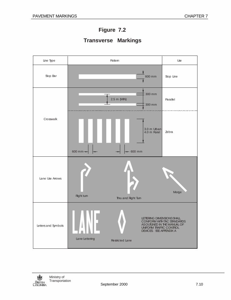
PAVEMENT MARKINGS CHAPTER 7
September 2000 7.10
Ministry ofTransportation
Line Type Pattern Use
Figure 7.2
Transverse Markings
600 mm
300 mm
300 mm
2.5 m (MIN)
3.0 m Urban4.0 m Rural
600 mm 600 mm
Lane Lettering
LETTERING DIMENSIONS SHALLCONFORM WITH TAC STANDARDSAS OUTLINED IN THE MANUAL OFUNIFORM TRAFFIC CONTROLDEVICES. SEE APPENDIX A
Stop Bar
Crosswalk
Lane Use Arrows
Right turnThru and Right Turn
Merge
Restricted Lane
Letters and Symbols
Stop Line
Parallel
Zebra

CHAPTER 7 PAVEMENT MARKINGS
September 2000 7.11Ministry ofTransportation
CL
Figure 7.3
Left / Right Turn Arrow
0.6 m
0.15 m
0.6 m
0.4 m
2.4 m
0.45 m
0.8 m
0.3 m
2
3
3
DIRECTION AND SEQUENCE OF LAYOUT
1
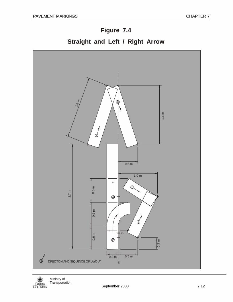
PAVEMENT MARKINGS CHAPTER 7
September 2000 7.12
Ministry ofTransportation
1 DIRECTION AND SEQUENCE OF LAYOUT CL
Figure 7.4
Straight and Left / Right Arrow
1.5
m
0.5 m0.3 m
0.5 m
0.3
m
0.6
m0.
6 m
0.6
m
1.0 m
2.7
m
1.6
m
2
4
6
5
1
3
0.6 m

CHAPTER 7 PAVEMENT MARKINGS
September 2000 7.13Ministry ofTransportation
CL
Figure 7.5
Advance Crossing Marking
6.0
m
0.6 m
1.0 m
NOTE: USED IN ADVANCE OF CROSSINGS SEE FIGURE 7.42 & 7.46 FOR DETAILS
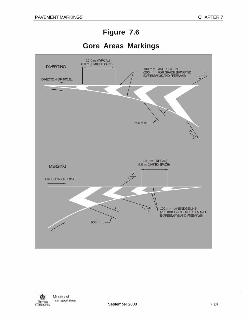
PAVEMENT MARKINGS CHAPTER 7
September 2000 7.14
Ministry ofTransportation
Figure 7.6
Gore Areas Markings
DIVERGING
MERGING
600 mm
1
1
1
2
2
2
100 mm LANE EDGE LINE(200 mm FOR GRADE SEPARATEDEXPRESSWAYS AND FREEWAYS)
100 mm LANE EDGE LINE(200 mm FOR GRADE SEPARATEDEXPRESSWAYS AND FREEWAYS)
6.0 m (LIMITED SPACE)
6.0 m (LIMITED SPACE)
10.0 m (TYPICAL)
10.0 m (TYPICAL)
600 mm
21DIRECTION OF TRAVEL
DIRECTION OF TRAVEL
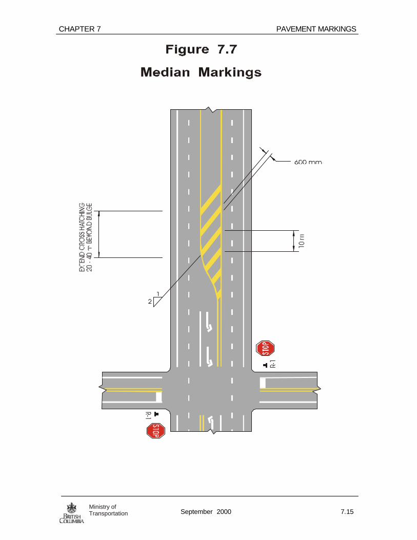
CHAPTER 7 PAVEMENT MARKINGS
September 2000 7.15Ministry ofTransportation

PAVEMENT MARKINGS CHAPTER 7
September 2000 7.16
Ministry ofTransportation
W-25
W-54D
W-25
Figure 7.8
Freeway /Expressway Off-Ramp Markings
10 m10
m
200 mmEDGE LINE
200 mm CONTINUITYLINE, 3m LINE - 3m GAP
8 SE
CO
NDS
OF
TRAV
ELTIM
E AT
PO
STED
SPE
ED L
IMIT
SEE
TABL
E 7.
1
8 SE
CO
NDS
OF
TRAV
ELTIM
E AT
PO
STED
SPE
ED L
IMIT
SEE
TABL
E 7.
1
100 mmEDGE LINE
WHERE DIVERGINGEDGE LINES BECOME200 mm IN WIDTH
10 m
10 m
NOTE: IF THE DISTANCE BETWEEN 200 mm LINES IS < 200 m THEN CONNECT THE 200 mm LINES.
W-54D

CHAPTER 7 PAVEMENT MARKINGS
September 2000 7.17Ministry ofTransportation
NOTE: IF THE DISTANCE BETWEEN 200 mm LINES IS < 200 m THEN CONNECT THE 200 mm LINES.
Figure 7.9
Freeway / Expressway On-Ramp Markings
10
m
10 m
200 mm CONTINUITYLINE, 3m LINE - 3m GAP
4 SE
CO
ND
S O
F TR
AVEL
TIM
E AT
PO
STED
SPE
ED L
IMIT
SEE
TABL
E 7.
1
100 mmEDGE LINE
WHERE DIVERGINGEDGE LINES BECOME200 mm IN WIDTH
50 m MIN.OR TO PHYSICALBULLNOSE
50 m MIN.OR TO PHYSICALBULLNOSE
60 m
MIN
.
60
m M
IN.
W-37R W-37R
R-2
W-38

PAVEMENT MARKINGS CHAPTER 7
September 2000 7.18
Ministry ofTransportation
Figure 7.10
Freeways / Expressway Auxiliary Lane Markings
10 m
100 mmEDGE LINE
WHERE DIVERGINGEDGE LINES BECOME200 mm IN WIDTH
10 m
60 m
MIN
.
4 SECONDS OFTRAVEL TIME ATSPEED LIMIT (MIN.)
4 SECONDS OFTRAVEL TIME ATSPEED LIMIT
200 m MINIMUM(IF LESS, CONNECT200 mmCONTINUITY ANDEDGE LINES)
12 SECONDS OFTRAVEL TIME ATSPEED LIMIT
50 m MIN. ORTO BULLNOSE
100 mm EDGE LINE
200 mm EDGE LINE
200 mm CONTINUTIYLINE, 3m LINE - 3m GAP
100 mm LANE LINE
100 mm EDGE LINE
W-38
W-25
W-37RSEE TABLE 7.1FOR CALCULATEDDISTANCES.
W-54D

CHAPTER 7 PAVEMENT MARKINGS
September 2000 7.19Ministry ofTransportation
Figure 7.11Freeway / Expressway Dual Right Lane Exit Markings
W-25
10 m
100 mmEDGE LINE
WHERE DIVERGINGEDGE LINES BECOME200 mm IN WIDTH
10 m
8 S
EC
ON
DS
OF
TR
AV
EL
TIM
E A
T P
OS
TE
D S
PE
ED
LIM
ITS
EE
TA
BL
E 7
.2
W- 5
4D
REFER TO TABLE 7.1FOR ARROW SPACING

PAVEMENT MARKINGS CHAPTER 7
September 2000 7.20
Ministry ofTransportation
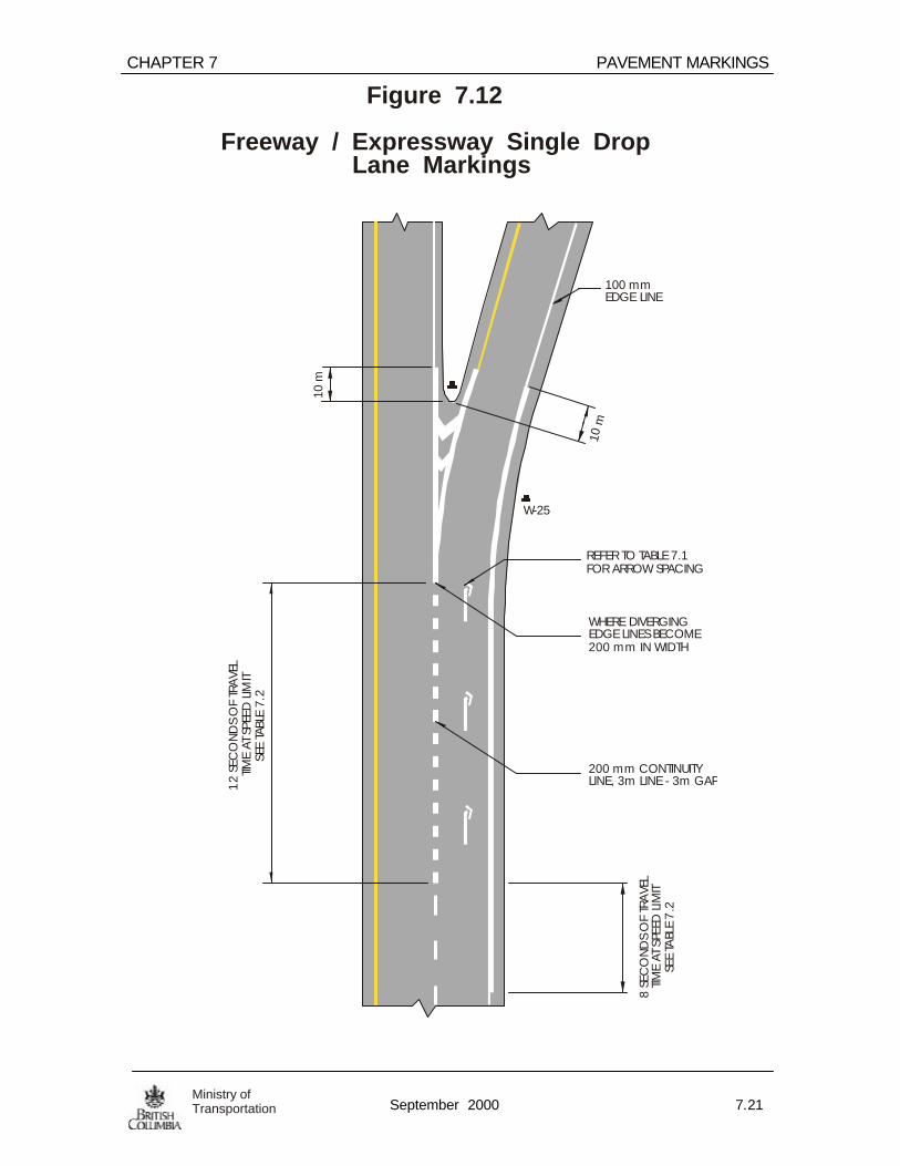
CHAPTER 7 PAVEMENT MARKINGS
September 2000 7.21Ministry ofTransportation
W-25
Figure 7.12
Freeway / Expressway Single Drop Lane Markings
10 m
100 mmEDGE LINE
10 m
200 mm CONTINUITYLINE, 3m LINE - 3m GAP
WHERE DIVERGINGEDGE LINES BECOME200 mm IN WIDTH
REFER TO TABLE 7.1FOR ARROW SPACING
12
SEC
ON
DS
OF
TRA
VEL
TIME
AT S
PEED
LIM
ITSE
E TA
BLE
7.2
8 SE
CO
ND
S O
F TR
AVE
LTIM
E AT
SPE
ED L
IMIT
SEE
TABL
E 7
.2
CHAPTER 7 PAVEMENT MARKINGS
February 2002 7.21Ministry ofTransportation
7.5.0 Delineation
Road-edge delineation, through the use of barrier or post mounted reflectors, orlane edge delineation through the use of raised pavement markers, is an effectiveaid for night driving. Delineation should be used where there are changes inhorizontal alignment, particularly at locations where the night accident frequency ishigh or the alignment at night is confusing
Delineation is to be considered as guide markings rather than warning devices andshall never be substituted for a proper warning sign
7.5.1 Raised Pavement Marker (RPMs) – Lane Edge Delineation
RPMs may be reflective or non-reflective. The following sections generally refer toreflective RPMs. For discussion on non reflective RPMs, especially when used asreplacement for markings, see Sec. C2.9.3 of the MUTCD for Canada
RPMs are often used on coastal routes to provide additional guidance. Snowplowing will damage surface reflectors, therefore they are generally not used in areaswhich receive large or frequent snowfalls. Installation of RPMs shall be approved bythe Regional Traffic Engineer.
RPMs are not required in urban areas with street lighting and a posted speed of 50km/h or lower. RPMs are not installed within an intersection.
In order to reduce snowplow damage, RPMs may be recessed from the top ofpavement by grinding a longitudinal slot in the asphalt. This slot shall be 1.3 m long.The width and depth of the slot will be governed by the type of reflector chosen.Depending on product, typical widths of cut will vary from 108 mm to 154 mm. RPMsare to be set “flush” with top of pavement surface. A typical depth, is 20 mm at thecentre, tapering out to 0 mm at each end of the slot.
RPMs must be approved for use by the Ministry of Transportation EngineeringBranch. Approved RPMs are listed in the “Recognized Product List” available fromthe Engineering Branch.
The District Transportation Office shall keep a list of highway where RPMs havebeen installed.

PAVEMENT MARKINGS CHAPTER 7
February 2002 7.22
Ministry ofTransportation
7.5.2 RPM Spacing1:
• 26.0m maximum where 5.0m dash and 8.0m gap is used
• 18.0m maximum where 3.0m dash and 6.0m gap is used.
• 13.0m for left turn lanes (see Fig. 7.13)
• 300mm in advance of dashed lines
• 50mm to right of median lane line where applicable
7.5.3 RPM – Reflective White Mono-Directional
• Used on lane lines separating traffic in the same direction of travel
7.5.4 RPM – Reflective Yellow Mono-Directional • used on the median line on freeways and other multilane highways divided by a
non-traversable median. 7.5.5 RPM – Reflective Yellow Bi-Directional • Used on directional dividing lines and to outline median crosshatched markings .
(See Figure 7. 13) • Used on two-way left turn lanes spaced at 9.0 m to face each direction of travel.
1 Where warranted and approved by the RTE, spacing may be reduced and RPMs installed at everydashed line , ref: Sec. C2.9.2 of the MUTCD for Canada

CHAPTER 7 PAVEMENT MARKINGS
February 2002 7.23Ministry ofTransportation
7.5.6 RPM – Reflective Red and White Bi-Directional
• Use for two-way delineation in controlling wrong way traffic movements ondivided highways, off or on ramps, and one-way streets.
7.6.0 CMB, CRB & Post Mounted Reflectors – Road Edge Delineation
7.6.1 CMB / CRB Reflectors
The color and spacing of reflectors mounted on long continuos sections of ConcreteMedian and Roadside Barriers is governed by the same guidelines as specified forpavement mounted RPMs (See Section 7.5.2.1 for spacing). 2
On isolated curves with CRB, the barrier mounted reflector may be spaced inaccordance to Table 7.4a if the curve radius is known. Alternatively, if the curveradius is unknown the delineator spacing may be based on Table 7.4b using theposted curve advisory speed.
2 CMB/CRB warrants a higher level of delineation since they represent a physical entity within the roadprism, therefore reflector spacing is limited to a maximum 26m

PAVEMENT MARKINGS CHAPTER 7
February 2002 7.24
Ministry ofTransportation
7.6.2 Post Mounted Delineation
Post mounted reflectors should be 150 x 150cm W-55 mounted on suitablesupports such as square steel posts or wood posts. Flexible delineator posts withfactory installed retroreflective sheeting may also be used. Refer to Section 635 ofthe Standard Specification for Highway Construction for approved delineatorsupports and installation details
The W-55 may be substituted with an approved equivalent reflector having at least225 square cm of retroreflective area and an RA equivalent to prismatic lenssheeting.
Table 7.3 Application Guidelines for Delineation
FREEWAY & EXPRESSWAY CONVENTIONAL HIGHWAY
CURVE TANGENT INTERCHANGE* CURVE TANGENT
WHITE (Right) Mandatory Recommended Recommended Optional ** OptionalYELLOW(Median)
Mandatory*** Recommended Mandatory N/A N/A
SPACING SEE TABLE 7.4a 60m 30m SEE TABLE 7.4a 60m* ALSO APPLIES TO INTERCHANGES ON CONVENTIONAL HIGHWAYS
** MANDATORY ON ACCIDENT PRONE CURVES
*** ONLY FOR RH CURVES <2000M RADIUS
Two-lane highway delineation shall consist of a reflector mounted on a suitablepost. Reflectors shall be erected so that the approach face is approximatelyperpendicular to the highway centreline.
MEDIAN BARRIER ROADSIDE BARRIER
WHITE
YELLOW
Alternate: top mounted reflectors
Note: top or side mountedreflectors may be RPM typeunits or flexible plastic “T” shape reflectors.

CHAPTER 7 PAVEMENT MARKINGS
February 2002 7.25Ministry ofTransportation
Reflector colour always correspond to the colour of the pavement markings. E.g.right shoulder reflector = white, left median reflector = yellow, left shoulder reflector= white.
Reflectors shall be erected on the right-hand side of the roadway for delineating left-hand curves and on the left for similar right-hand curves. Reflectors will always belocated on the outside of curves. For those curves which are require delineation inboth directions, two reflectors should be used on each post throughout the curve sothat one reflector is visible for each direction of travel. In this cases it may benecessary to rotate individual posts away from the standard position (approach faceperpendicular to centreline) in order to obtain a maximum effect. The spacing ofreflectors through horizontal curves is shown in Table 7.4a. (see Figure 7.14)

PAVEMENT MARKINGS CHAPTER 7
February 2002 7.26
Ministry ofTransportation
7.6.2 Post Mounted Delineation (Cont’d)
The use of delineation on straight sections of roadway is optional but may bespecified by the Regional Traffic Engineer. When delineation is specified in thiscase, the reflectors should be spaced 60 m apart.
Where driveways, side roads or other obstructions interrupt this regular spacing, thereflector affected shall be moved a distance not to exceed one-quarter of the normalspacing, or omitted. Where continuous roadside barriers exist, refer to Section7.5.2.
Delineation is required at all interchanges regardless of illumination.
Typical Reflector Application
DIVIDED HIGHWAYS
TWO LANE CONVENTIONAL HIGHWAY
White (
if use
d)
Whit
e
White
White

CHAPTER 7 PAVEMENT MARKINGS
February 2002 7.27Ministry ofTransportation
7.6.3 Active “Lighted” Delineation Systems
Active delineators may be in-road, on barrier or on delineator posts. They may bepowered by solar energy, batteries, or hard wired power supply systems and mostutilize LED’s (light emitting diodes). They have a higher purchase and installationcost so they are typical only used at locations where a high level of delineation iswarranted.
Active delineators have the advantage of being visible from a greater distance thanunlit delineators. They do not rely on vehicle headlights for illumination. Activedelineators emit light so they can be seen from a greater distance, typically > 1 km.
Active delineation systems are generally limited to higher volume highways and maybe considered for use on: accident-prone curves, areas prone to fog and/or rain, orwhere geometric condition demand a high level of positive guidance. The unitsshould be used such that the light output of active delineators improves driverguidance and safety. Hence these devices should not be used in a location ormanner that causes driver distraction.
Site suitability is an important consideration. Areas of continuous shade may not begood candidates for solar power and illuminated urban areas may not be a goodarea for active delineators in general. Also, active delineators may be more at riskof vandalism due to their novelty.
Active delineators are spaced in accordance to 7.5.2 unless otherwise directed bythe Sr. Traffic & Electrical Engineer.
The observation angle of active delineator is determined by the beamwidth of theLED. Therefore the beamwidth of the LED will influence how delineator must beoriented in relation to the curvature of the road. LED’s with beamwidths of ≤40°require critical alignment to optimize their visibility. LED’s with beamwidths of ≥40°usually can be installed with the centre of the LED in line with the barrier.
Use of active delineators must be recommended by the R.T.E. and must beapproved by the Sr. Traffic & Electrical Engineer.

PAVEMENT MARKINGS CHAPTER 7
February 2002 7.28
Ministry ofTransportation
RD.
RD.
Figure 7.13
Raised Pavement Markers (RPMs)
RAIS
ED IS
LAN
D
R-14R
W-54L
R-1
R-1
5
5
8
88
8
26 m
18 m
13 m
66
3
300
mm
300
mm
OPTIONALFLASHER
Note: Where the systematic spacing of RPMs is interrupted by a cross street, railway etc., an RPM may be moved in either direction for a distance not exceeding ¼ of the normalspacing. If the RPM still obstructs, it should be left out and the normal spacing continued as though as RPMs were in place.

CHAPTER 7 PAVEMENT MARKINGS
February 2002 7.29Ministry ofTransportation
Figure 7.14
Reflector / RPM Spacing On Horizontal Curves
6.0 S
6.0 S
3.0 S
3.0 S
1.8 S
1.8 S
S
S
SSS
SX
SS
SS
BEGINNING OF CURVE
R
R
Radius (m)
Note: 1. Divide the X distance among all spacingsso at least the last reflector falls at the end of the curve
2. Spacing between reflectors not to exceed 60m.
3. Reflectors shall be installed perpendicular to oncoming traffic
Table 7.4a Spacing of Reflectors onHorizontal Curves (R Known) Table 7.4b (R unknown)
S R= 2 0 3.

PAVEMENT MARKINGS CHAPTER 7
February 2002 7.30
Ministry ofTransportation
Figure 7.15
Delineators & RPM’s on Freeway / Expressway Ramps
REFLECTORSPACED AT 60 m.
REFLECTORSPACED AT 60 m.
30 m
W-54D
Optional double reflector(1 minimum required)
Optional double reflector(1 reflector minimum required)
Delineators spacedat 30m for entry andexit ramps

CHAPTER 7 PAVEMENT MARKINGS
February 2002 7.31Ministry ofTransportation
BLANK
PAVEMENT MARKINGS CHAPTER 7
February 2002 7.32
Ministry ofTransportation
BLANK

CHAPTER 7 PAVEMENT MARKINGS
February 2002 7.33Ministry ofTransportation
BLANK


CHAPTER 7 PAVEMENT MARKINGS
September 2000 7.33Ministry ofTransportation
7.7 Restricted Lanes (Bus/HOV Lanes)
A full time restricted lane is reserved for the exclusive use of Buses and HighOccupancy Vehicles. The lane is separated from a normal through lane by a 200mm wide lane line. At intersections/interchanges where right/left turns are permittedthe 200 mm wide lane line shall be dashed to permit lane changes. The dashed lineshall consist of a 6 m line and a 3 m gap. The length of the line is defined in Figure7.18. A 100 mm wide lane line shall be broken with a 0.5 m line and 0.5 m gapacross the mouth of an at grade intersection.
At signalized intersections where right turns are permitted from the side street, therestricted lane shall be marked with a white line 200 mm in width on a 2:1 taper fromthe curb to the lane line. This line shall have a 1.5 m gap centered on the width of thethrough lane. The lane lines shall be solid for a minimum of 30 m from the start of theblock. This right turn pavement marking shall not be used for part time restrictedlanes. See Figure 7.17.
HOV or BUS LANE text pavement markings shall not be used for part time restrictedlanes. The elongated diamond symbol shall be used to supplement the signing onboth full-time and part-time restricted lanes.
The frequency of the restricted lane marking shall be based on posted speed, blocklength, distance from the intersections and engineering judgment. For urbanapplications where intersections are closely spaced, a minimum of one set ofmarkings shall be placed for each block. As a general rule, markings are to bespaced at four times the posted speed. ( e.g. for a 50 km/h posted speed, thespacing between markings would be 50 x 4 = 200 m)
Restricted lanes shall be painted to obtain a minimum width of 3.6 m. In areaswhere a lane width of 3.6 m is not obtainable, the Senior Traffic Engineer must beconsulted.

PAVEMENT MARKINGS CHAPTER 7
September 2000 7.34
Ministry ofTransportation
CL CL
Figure 7.16
Reserved Lane Markings
10 m FOR POSTED SPEEDOF 60 KM/H AND BELOW.
15 m FOR POSTED SPEEDABOVE 60 KM/H.
10 m FOR POSTED SPEEDOF 60 KM/H AND BELOW.
15 m FOR POSTED SPEEDABOVE 60 KM/H.
4.0 m
2.40 m
2.40 m
1.0 m 1.0 m
200 mm 200 mm
100 mmEDGE LINE
BUS AND HOV PAVEMENT MARKING SYMBOLS AND WORDED MESSAGES ARE TO BE REPEATED AT NOTE:200 m TO 280 m INTERVALS DEPENDING ON THE OVERALL LENGTH AND CONTINUITY OF THE LANE
200 mm CONTINUITYLINE, 3m LINE - 3m GAP
LETTERING DIMENSIONS SHALL CONFORM WITH TAC STANDARDS AS PER THE MANUAL OFUNIFORM TRAFFIC CONTROL DEVICES FOR CANADA. SEE APPENDIX A-2.
3.6 m MIN.3.6 m MIN.
0.2 m 0.2 mALL SPACES ALL SPACES
1.4 m 1.4 m1.3 m 1.3 m
0.95
m
0.95
m
0.95
m
0.95
m

CHAPTER 7 PAVEMENT MARKINGS
September 2000 7.35Ministry ofTransportation
RD.
Figure 7.17
Reserved Lane Right Turn Marking(Signalized Intersection)
1.5 m
EQUA
L
1
2
3.6 m MIN.
30 m
MIN
.
200 mm LANE LINE
R-211D
W-3
21
R-211L
R-220
OR
R-220

PAVEMENT MARKINGS CHAPTER 7
September 2000 7.36
Ministry ofTransportation
Figure 7.18
Reserved Lane MarkingsFull-Time Operation (Urban)
NOTE: *IF THE DISTANCE BETWEEN INTERSECTIONS ISGREATER THAN 200 m, ADDITIONAL D (R-211D/L)SIGNS MAY BE REQUIRED.
FOR RESTRICTED LANES OVER 1000 m IN LENGTH,ADDITIONAL B (I-200) SIGNS MAY BE REQUIRED.
SPEED L M N o/h N shld
50 KM/H 200m 10m 40m 20m60 KM/H 240m 10m 40m 20m70 KM/H 280m 10m 40m 20m
SPEED X Y
50 KM/H 105m 65m60 KM/H 120m 65m70 KM/H 130m 65m80 KM/H 140m 70m
FOR FURTHER INFORMATION ON SIGN APPLICATIONAND PLACEMENT SEE RESERVED/RESTRICTED LANESIGNING POLICY.
30 m
MIN
.S
EE
FIG
UR
E 5
.2X
YS
EE
NO
TE
AX
B
C
D
E
A
NM
MN
NL
2L*<
L*<
L
NOTE A:
-IF THE REMAINDER OF THE BLOCKIS LESS THAN 30 m THEN CONTINUEWITH BROKEN LINE.
OVERHEADAPPLICATIONS
SHOULDERAPPLICATIONS
E
C
A
B
D
R-211D
R-211D
R-211D
R-211D
R-211L
R-211L
R-211L
R-211L
R-222
R-221
R-220
R-222
R-221
R-220
R-240 R-240
200
mm
CO
NT
INU
OU
SL
INE
100
mm
LIN
E0.
5 m
LIN
E-
0.5
m G
AP
200
mm
LIN
E6
m L
INE
-3
m G
AP
W-3
21
R-1
R-1

CHAPTER 7 PAVEMENT MARKINGS
September 2000 7.37Ministry ofTransportation
Figure 7.19
Reserved Lane MarkingsPart-Time Operation (Urban)
NOTE: *IF THE DISTANCE BETWEEN INTERSECTIONS ISGREATER THAN 200 m, ADDITIONAL (R-216D/L)SIGNS MAY BE REQUIRED.
FOR RESTRICTED LANES OVER 1000 m IN LENGTH,ADDITIONAL B (I-200) SIGNS MAY BE REQUIRED.
FOR FURTHER INFORMATION ON SIGN APPLICATIONAND PLACEMENT SEE RESERVED/RESTRICTED LANESIGNING POLICY.
B
C
D
E
A
10 m
MM
10 m
10 m
L
2L*<
L*<
L ALTERNATE
E
C
A
B
D
R-216L
R-216L
R-216L
R-216L R-215
R-215
R-222
R-221
R-220
R-222
R-220
R-240
R-1
R-1

PAVEMENT MARKINGS CHAPTER 7
September 2000 7.38
Ministry ofTransportation
Figure 7.20
Bus Lane Markings
C
D
E
C
D
E
A
A
VARI
ABLE
LEN
GTH
100
m30
mTA
PER
40 m
50 m
MM
30 m
200
mm
CO
NTIN
UOUS
LINE
200
mm
LIN
E3
m LI
NE-
3 m
GAP
FOR FURTHER INFORMATION ON SIGN APPLICATIONAND PLACEMENT SEE RESERVED LANE SIGNING POLICY.
OVERHEADAPPLICATIONS
SHOULDERAPPLICATIONS
R-201L
R-201L
R-201L
R-201L
R-201D
R-201D
R-201D
R-201D
R-221 R-221
R-220R-220
R-222R-222
L*IF THE DISTANCE BETWEEN INTERSECTIONS ISGREATER THAN 200 m, ADDITIONAL D (R-201D/L)SIGNS MAY BE REQUIRED.
SEE Figure 7.37 FOR TAPER, D, P, AND T DIMENSIONS
*<L
*<L
NOTE:
SPEED L M60 KM/H 240m 10m70 KM/H 280m 10m80 KM/H 320m 10m90 KM/H 360m 10m
W-61RW-61T
W-61R
D+
P
30 TO
50 m
TL

CHAPTER 7 PAVEMENT MARKINGS
September 2000 7.39Ministry ofTransportation
160 m MIN.
160 m MIN.
0.0 m OFFSETPREFERRED
Figure 7.21
Signalized Intersection Markings -Curb & Gutter

PAVEMENT MARKINGS CHAPTER 7
September 2000 7.40
Ministry ofTransportation
1.2 m MIN.
0.0 m OFFSETPREFERRED
1.0 m1.0 m
Figure 7.22
Skewed Signalized Intersection Markings

CHAPTER 7 PAVEMENT MARKINGS
September 2000 7.41Ministry ofTransportation
Figure 7.23
Signalized Intersection Markings(Open Shoulder Design)
NOTE: WHERE THERE IS NO MARKED CROSSWALK, THE STOP LINE SHALL BE SET BACK FROMTHE INTERSECTION TO ALLOW FOR A FUTURE CROSSWALK.
1.0 m600 mm
2.5 m (MIN.)
0.4 m
3.0 m
100 mm CONTINUITYLINE, 3m LINE - 3m GAP
R-9
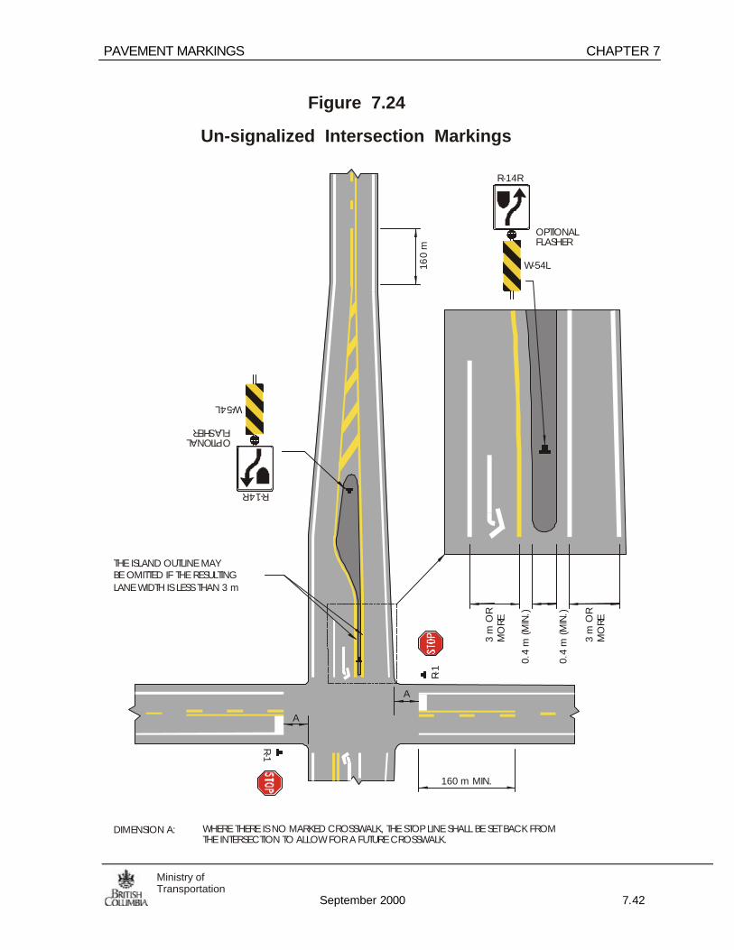
PAVEMENT MARKINGS CHAPTER 7
September 2000 7.42
Ministry ofTransportation
Figure 7.24
Un-signalized Intersection Markings
DIMENSION A: WHERE THERE IS NO MARKED CROSSWALK, THE STOP LINE SHALL BE SET BACK FROMTHE INTERSECTION TO ALLOW FOR A FUTURE CROSSWALK.
A
A
R-14R
W-54L
R-14R
W-54L
R-1
R-1
160 m MIN.
160
m
OPTIONALFLASHER
OPTIONALFLASHER
THE ISLAND OUTLINE MAYBE OMITTED IF THE RESULTINGLANE WIDTH IS LESS THAN 3 m
3 m
OR
MO
RE
3 m
OR
MO
RE
0.4
m (M
IN.)
0.4
m (M
IN.)

CHAPTER 7 PAVEMENT MARKINGS
September 2000 7.43Ministry ofTransportation
Figure 7.25
Right Turn Acceleration and Deceleration Lane Markings
100 mm CONTINUITYLINE, 3 m LINE - 3 mGAP
R-1
R-1
IF TH
E LA
NE
WID
TH IS
WID
ER TH
AN 4
m TH
EN A
CO
NTIN
UITY
LINE
MUS
T BE
USE
D. M
AINT
AIN
THE
SAM
E LA
NE
WID
TH A
SPR
EVIO
US S
ECTIO
N TH
ROUG
H IN
TERS
ECTIO
N.
IF TH
E LA
NE
WID
TH IS
WID
ER TH
AN 4
m T
HEN
A C
ONT
INUI
TYLIN
E M
UST
BE U
SED.
MAI
NTAI
N TH
E SA
ME
LAN
E W
IDTH
AS
PREV
IOUS
SEC
TION
THRO
UGH
INTE
RSEC
TION
.
TPL
BPL
T
REFE
R TO
THE
MO
TH D
ESIG
N M
ANUA
L FO
R LE
TTER
ED D
IMEN
SIONS
& G
EOM
ETRI
C S
TAN
DARD
S
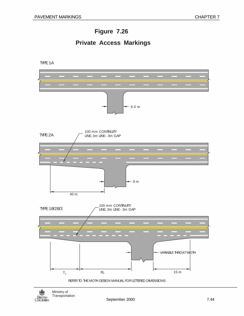
PAVEMENT MARKINGS CHAPTER 7
September 2000 7.44
Ministry ofTransportation
Figure 7.26
Private Access Markings
6.0 m
9 m
VARIABLE THROAT WIDTH
100 mm CONTINUITYLINE, 3m LINE - 3m GAP
100 mm CONTINUITYLINE, 3m LINE - 3m GAP
TYPE 1A
TYPE 2A
TYPE 1B/2B/3
40 m
T 1 P.L. 15 m
REFER TO THE MOTH DESIGN MANUAL FOR LETTERED DIMENSIONS

CHAPTER 7 PAVEMENT MARKINGS
September 2000 7.45Ministry ofTransportation
7.8 Left Turn Lane Pavement Markings
All left turn lanes must be approved by the Regional Traffic Engineer prior to painting.
Left turn lanes must be constructed to the standards shown in the MoTH DesignManual before painting.
100 mm, 1 m line - 1 m gap continuity lines may be used across the throat of left turnslots where the alignment restricts the visibility of the pavement markings.
At intersections with dual left turns, continuity lines should be used to delineate thetwo turn lanes. The continuity lines shall be marked such that the design vehiclespecified for the geometric design can turn in the outside lane and a smaller vehiclein the inside lane can turn simultaneously. The design vehicle for the inside lanemovement will depend on the local traffic conditions and mix.
7.8.1 Rural
Short continuity dash markings (3.0 m gap and 3.0 m line) shall not be marked onrural left turn lane designs except in special circumstances (e.g. a sharp curve withlimited sight distance.
7.8.2 Urban
The urban left turn lane marking shown in Figure 7.28 may be used where the speedlimit is less than or equal to 60 km/h.

PAVEMENT MARKINGS CHAPTER 7
September 2000 7.46
Ministry ofTransportation
Figure 7.27
Left Turn Lane Markings (Rural)
AT "4 LEGGED" INTERSECTION AT "T" INTERSECTION
AB
CD
D2
2 m
A
10 m
600 mm
1
2
3.6
m
3.6
m
4.5
m
4.0
m
4.0
m
3.6
m
3.6
m
4.0
m
1.8
m1
.8 m 4.
0 m
R 22
1.8
m
1.8
m
1.8
m1.
5 m
1.5
m
0.3
m
0.3
m
0.3
m1.
5 m
R-1
R-1
R-1
1.3
m1
.8 m
REFE
R TO
TH
E M
OTH
DES
IGN
MA
NUA
L FO
R LE
TTER
ED D
IMEN
SIO
NS
R-15
0
R- 15 0

CHAPTER 7 PAVEMENT MARKINGS
September 2000 7.47Ministry ofTransportation
REFE
R TO
THE
MO
TH D
ESIG
N M
ANUA
L FO
R LE
TTER
ED D
IMEN
SIO
NS
Figure 7.28
Left Turn Lane Markings (Urban)
AT "4 LEGGED" INTERSECTION AT "T" INTERSECTION
CA
D
D22
mA
10 m
1
2
3.6
m
3.6
m
4.0
m
4.0
m
4.0
m
3.6
m
3.6
m
4.0
m
1.8
m1.
8 m 4.0
m
R 22
1.8
m
1.8
m
1.8
m1.
5 m
1.5
m
0.3
m
0.3
m
0.3
m1.
5 m
R-1
R-1
R-1
33
3 600 mm

PAVEMENT MARKINGS CHAPTER 7
September 2000 7.48
Ministry ofTransportation
Figure 7.29
Long Load Left Turn Lane Markings
55 m
3.6
m
4.0
m2.
5 m
4.0
m
4.0
m
3.6
m
3.6
m
3.6
m
4.5
m
2.8
m4.
0 m
30
m3
0 m
BP.L
.
T
55 m
STO
RAG
EAN
D D
ECEL
ERAT
ION
C
A
REFE
R TO
THE
MO
TH D
ESIG
N M
AN
UAL
FO
R LE
TTER
ED D
IMEN
SIO
NS
100 mm CONTINUITYLINE, 3m LINE - 3m GAP
4.0
m4.
0 m
W-54LW-54L
W-54D
W-54D

CHAPTER 7 PAVEMENT MARKINGS
September 2000 7.49Ministry ofTransportation
Figure 7.30
Protected “T” Intersection Markings
XYZRD.
R-1W-54D
W-54DW
-54D
R-14R
W-54L
R-14R
W-54L
OPTIONALFLASHER
OPTIONALFLASHER
W-54L

PAVEMENT MARKINGS CHAPTER 7
September 2000 7.50
Ministry ofTransportation
RD.
Figure 7.31
Dual Left Turn Lane Markings(Signalized Intersection)
0.5/ 0.5/0.5 WHITE GUIDING LINES
NOTE: GUIDING LINES MAY BE USED FOR SINGLE LEFT TURN LANES IF THE VERTICAL ALIGNMENTAT AN INTERSECTION SECLUDES THE LONGITUDINAL MARKINGS ON THE FAR SIDE OF THEINTERSECTION.
R-15
0
R-150
R-109L
R-109L0.5/ 0.5/0.5 YELLOW GUIDING LINES IF WARRANTED

CHAPTER 7 PAVEMENT MARKINGS
September 2000 7.51Ministry ofTransportation
7.9 Two Way Left Turn Lanes
7.9.1 General
Two way left turn lanes (TWLTL) are an effective median treatment for urban andsuburban collectors and arterials when mid block access to a large number of lowvolume driveways is required. They are applicable when pedestrian crossingvolumes are low and signalized intersections are few and widely spaced.
See The MoTH Design Manual for further details.
7.9.2 Application:
The TWLTL is typically restricted to urban/suburban roads where posted speeds area maximum 60 km/h. The TWLTL treatment is not recommended for use on ruralhighways as it restricts mobility.
7.9.3 Median Lane Width
From 3.0 to 5.0 m.
The recommended width on provincial highways is 4.6 m, to allow for theconventional one way left turn lane development at major intersections.
The width of the median TWLTL should be equal to or greater than the adjacentthrough lanes. TWLTL widths less than 3.5 m should only be used in urban areaswhere the posted speed is 50 km/h or less.
7.9.4 Intersection Treatment
TWLTL lane markings are interrupted at minor cross streets and conventional one-way left-turn lane treatment are used for major cross streets. See Figure 7.32 Highvolume accesses should be treated as major intersections.

PAVEMENT MARKINGS CHAPTER 7
September 2000 7.52
Ministry ofTransportation
R-1
R-1
Figure 7.32
Two Way Left Turn Lane Markings
A MINIMUM OF ONE SET OF LEFT TURN ARROWS SHALL BE PAINTED IN THE MIDDLE OF A SHORTTWO WAY LEFT TURN LANE.
CONJUNCTION WITH THE PLACEMENT OF R-150A SIGNS.
OF TRANSITION. FOR RAISED ISLANDS INSTALL 3 - 5 CROSS-HATCH MARKINGS BEYONDCHANNELIZATION.
NOTE:
SETS OF LEFT TURN ARROWS SHALL BE PAINTED 100 m FROM AN INTERSECTION AND IN
MINOR CROSS STREET(UNSIGNALIZED)
MAJOR CROSS STREET(SIGNALIZED)
See Figure 2.5 for signing details
4.6 m STANDARD WIDTH
DRIVEWAY
DRIVEWAY
DRIVEWAY
FOR PAINTED LEFT TURN SLOT DESIGNS, INSTALL CROSS-HATCH MARKINGS TO THE WIDEST POINT
LEFT TURN ARROWSSPACED 2.0 m APART
33
6

CHAPTER 7 PAVEMENT MARKINGS
September 2000 7.53Ministry ofTransportation
7.10 No Passing Zones
No-passing zones shall be established using a “barrier” line (solid yellow line) atvertical or horizontal curves and at any location on two and three-lane highwayswhere passing in one direction must be prohibited because of restricted sightdistances or other unsafe conditions.
7.10.1 Barrier Lines
7.10.1.1 Sight Distance
A no-passing zone where sight distance is restricted shall be one inwhich the sight distances ahead are equal to or less than that listedbelow for the posted speed limit:
Posted Speed Limit (km/h) Distance (m)
50 160*60 200*70 240*80 275*90 330*100 400*110 475*
* These distances, when applied in the field are modified slightly to conform to the13 metre dash line cycle (5 (m) dash & 8 (m) space).
7.10.1.2 Minimum Passing Zone Lengths
If a passing zone in one direction lies between successive no-passingzones, the actual passing zone or segment of dashed lines cannot beless than the distance as stated above. If the length is less than thisdistance, then the passing zone should be eliminated and made no-passing by the use of a double solid yellow line.
Minimum passing length equalssight distance from above

PAVEMENT MARKINGS CHAPTER 7
September 2000 7.54
Ministry ofTransportation
7.10.1.3 Single to Double Centre line Transitions
At locations where single dashed directional dividing lines (passingzone) would lead into a double solid directional dividing line (no-passing zone) then a single barrier line should be extended for aminimum of the sight distance dimension into the passing zone fortraffic approaching a barrier line. This extension will shorten thepassing zone for approaching drivers, however, this extension willprovide an additional safety buffer for those drivers already carryingout passing maneuvers in this direction.
When transitioning from a single centre line to a double centre line witha solid barrier and dashed line, the barrier line should meet the sightdistance criteria. If it doesn’t then the single centre line should be solidfor a sufficient length to meet the applicable sight distance. Thiscircumstance commonly occurs where rural roads tie in with their urbancounterparts.
Barrier line must equalor exceed minimumdistance per 7.10.1.1
7.10.1.4 Miscellaneous Application of Barrier Lines
Barrier lines shall be marked, unless otherwise instructed, at all pointsas follows:
a. Where sight distance is restricted because of either vertical orhorizontal curvature, or both.
b. On each approach to a signalized intersection
c. On the approach to an intersection of two or more numberedroutes or an intersection with a left turn lane
d. On the approach to left hand painted or curbed islands
e. On the approach to a beginning of a three lane section ofhighway with a barrier line length corresponding to the sightdistance.

CHAPTER 7 PAVEMENT MARKINGS
September 2000 7.55Ministry ofTransportation
7.10.2 Field Measurement of Barrier Lines
Field measurement of barrier lines should be done in accordance with the generalmethodology described in Section C2.2 of the Manual of Traffic Control Devicesfor Canada, except eye height is based on approximately 1.5 m and the target heightis approximately 0.6 m
_____________________________________________________

PAVEMENT MARKINGS CHAPTER 7
September 2000 7.56
Ministry ofTransportation
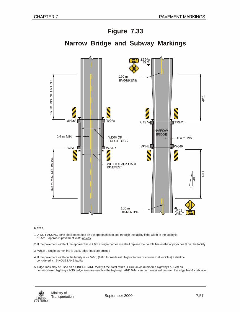
CHAPTER 7 PAVEMENT MARKINGS
September 2000 7.57Ministry ofTransportation
Figure 7.33
Narrow Bridge and Subway Markings
NARROWBRIDGE
40:
14
0:1
40
160
m M
IN. N
O P
ASS
ING
160
m M
IN.
NO
PAS
SIN
G
WIDTH OFBRIDGE DECK
WIDTH OF APPROACHPAVEMENT
W-51W-51T
W-51TW-51
W-54R
W-54R
W-54R
W-54R
W-54L
W-54L
W-54L
W-54L
0.4 m MIN.
1
0.4 m MIN.
160 mBARRIER LINE
160 mBARRIER LINE
Notes:
1. A NO PASSING zone shall be marked on the approaches to and through the facility if the width of the facility is 1.25m + approach pavement width
2. If the pavement width of the approach is < 7.0m a single barrier line shall replace the double line on the approaches & on the facility
3. When a single barrier line is used, edge lines are omitted
4. If the pavement width on the facility is <= 5.0m, (6.0m for roads with high volumes of commercial vehicles) it shall be considered a SINGLE LANE facility
5. Edge lines may be used on a SINGLE LANE facility if the total width is >=3.5m on numbered highways & 3.2m on non-numbered highways AND edge lines are used on the highway AND 0.4m can be maintained between the edge line & curb face
or less

PAVEMENT MARKINGS CHAPTER 7
September 2000 7.58
Ministry ofTransportation
Figure 7.34
Cattle Guard Approach Markings
160 m M
IN. N
O PA
SSING
160 m M
IN. N
O PASSIN
G
160 m
MIN. SO
LID LIN
E
160 m
MIN
. SOLID
LINE
W-54R W-54R
W-54R W-54R
W-54L W-54L
W-54L W-54L
W-046
W-046

CHAPTER 7 PAVEMENT MARKINGS
September 2000 7.59Ministry ofTransportation
Figure 7.36
Slow-Moving Vehicle Pullout MarkingsI-4
5
I -43
TAPER LENGTH TAPER LENGTH
1m LINE - 1m GAP100 mm WIDE
1m LINE - 1m GAP100 mm WIDE WHERE ADEQUATE SIGHT
DISTANCE IS AVALIABLEPASSING MAY BEPERMITTED
100 mm WIDE EDGE LINE
P-1R
P-1D P-1DP-1L

PAVEMENT MARKINGS CHAPTER 7
September 2000 7.60
Ministry ofTransportation
Figure 7.37
Passing / Climbing Lane Markings& Sign Placement
NOTE: CONTINUOUS BARRIER LINES SHALL BE MARKED IN THE SINGLE LANE DIRECTION REGARDLESS OF THESIGHT DISTANCE UNLESS APPROVED FOR DOWNHILL PASSING BY THE SENIOR TRAFFIC ENGINEER.
PASSING IN THE SINGLE LANE DIRECTION MAY BE ALLOWED ONLY WHERE THE PASSING SIGHTDISTANCE IS ADEQUATE AND WHERE S.A.D.T. VOLUME IS LESS THAN 4000 VEHICLES. OTHERWISE,PASSING IN THE SINGLE LANE DIRECTION SHOULD BE PROHIBITED BY A BARRIER LINE.
W-61R
W-61RW-61T
R-7
160
m
160
m
DP
T
R-55
SEE NOTE
TAPE
R
DELINEATORS SPACED AT 10 m(OPTIONAL)
30 m
MIN
.
50
m40
m
THE R-55 SIGN SHALL BEPLACED AT THE START OFEACH SINGLE LANE PASSINGSECTION AND AT 800 mINTERVALS THEREIN.
Posted SpeedLimit (km/h)
Taper (m) D ( m)
50 110 4060 130 5070 150 60

CHAPTER 7 PAVEMENT MARKINGS
September 2000 7.61Ministry ofTransportation
Figure 7.39
Transitional MarkingsFour Lanes to Two Lanes
50 m40 m
W-61R
W-61T
W-61R
T
50 - 100 m
P D
SEE TABLE (ABOVE)
R-7
DELINEATORS SPACED AT 10 m(OPTIONAL)
Figure 7.38
Transitional Markings:Four Lanes, Divided to Undivided
R-14
R
W-5
4L
W-4
8W
-48
10 m150 m - 300 m
DELINEATORS(OPTIONAL)
OPT
ION
AL
FLA
SHE
R SEE TABLE
TAPER FOR DIVIDED TOUNDIVIDED TRANSITION
SPEED RATIO
< 80 km/h 50:1 90 km/h 60:1
> 100 km/h 70:1
eg. AT A SPEED OF 80 km/h AND A MEDIANWIDTH OF 2.6 m THE MINIMUM LENGTH OF THE TAPER WOULD BE 65 m.(2.6 / 2 x 50 = 65 m)
“T” , “P” AND “D” DIMENSION FROM FIG. 7.37

PAVEMENT MARKINGS CHAPTER 7
September 2000 7.62
Ministry ofTransportation
OPTION 1
(PAVED SHOULDER < 1.0m)
OPTION 2 (Preferred)
(PAVED SHOULDER > 1.0m)
0.6 m TYP. 0.6 m TYP.
1.2 m
<1.0m
0.6 m
L/2 L/2
2.5 km
EDG
E O
FPA
VEM
ENT
EDG
E O
FPA
VEM
ENT
>1.0m
500m
CEN
TRE
LINE
CEN
TRE
LINE
LANE
LIN
E
LANE
LIN
E
LAN
E ED
GE
LINE
LAN
E ED
GE
LINE
VARI
ES
VARI
ES
R-100 R-100
R-100
LANE(L)
Figure 7.40
Aerial Speed Check Markings
Notes:
1. A Police Officer must assist & document the layout and measurement and repainting of these markings which would be submitted in court as evidence if a speeding violation is challenged.
2. Markings are white, non-reflectorized
3. A minimum of 6 markings shall be place 500m centre to centre
4. These markings should only be used on tangent highway segments

CHAPTER 7 PAVEMENT MARKINGS
September 2000 7.63Ministry ofTransportation
Figure 7.41
Parallel and Angle Parking Stall Markings
6.5 m MIN
300 mm
100 mm
6 m - 7.5 m
2.5 m
-3 m 5.5 m
7 - 7.5 m 7 - 7.5 m
100 mm LINE PAINTED ONTHE FACE OF THE CURB
100 m
m
100 mm
45
2.5
m
0.5 m

PAVEMENT MARKINGS CHAPTER 7
September 2000 7.64
Ministry ofTransportation
2.5m
XYZ RD.
SEE NOTE A
W-1
0(O
PTIO
NA
L)
W-10
W-1
0
W-10
W-10
W-1
0
R-1
R-1
R-35
R
R-35R
R-35
R
R-35RP-14
P-14
SEE NOTE B
160 mCL
3.0m
G-7
G-7
Figure 7.42
Railroad Crossing Markings
5.0 m MIN.
Note: For W-10 Placementrefer to Chapter 3
10.0m
Notes:
1. Stop lines shall be placed at crossings within 60m of major intersections. The “X” may be omitted in this situation
2. Stop lines shall be as close as practical to the crossing, but no closer than 5.0m to the nearest rail.

CHAPTER 7 PAVEMENT MARKINGS
September 2000 7.65Ministry ofTransportation
Figure 7.43
Fire Hall Markings
FIRE HALL/AMBULANCE
W-318L
W-318R
R-35R
R-35R
SEE
NOTE
160
m
160
m
SEE
NO
TE
NOTE: THE MINIMUM DISTANCE FROM THE STOP BAR TO FIRE SIGNAL LIGHT IS 15 m. THE MAXIMUMDISTANCE IS 25 m. THE OPTIMUM DISTANCE IS 20 m.
1m LINE - 1m GAP100 mm WIDE
I-167L
I-167R
Note: See W-318 warrant in Chapter 3 for location

PAVEMENT MARKINGS CHAPTER 7
September 2000 7.66
Ministry ofTransportation
Figure 7.44
Temporary/Detour Markings
300 mm 300 mm
0.5 m LINE - 8.0 m GAP
1/3 THE SIZE OF REGULAR ARROWS
100m
m
100m
m10
0mm
Notes:
1. Temporary Pavement marking tape shall be white or yellow (conforming to standard marking colours) and approved for Ministry use.
2. Temporary marking tape shall be reflective and easily removed from asphalt and smooth portland cement concrete surfaces
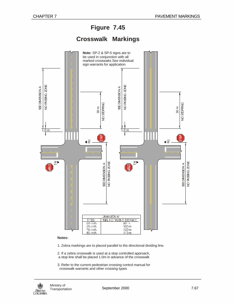
CHAPTER 7 PAVEMENT MARKINGS
September 2000 7.67Ministry ofTransportation
R-1
R-1
R-1
R-1
Figure 7.45
Crosswalk MarkingsSE
E D
IMEN
SIO
N A
SEE
DIM
ENSI
ON
A
SEE
DIM
ENSI
ON
A
SEE
DIM
ENSI
ON
A
NO
PA
SSIN
G Z
ON
E
NO
PA
SSIN
G Z
ON
E
NO
PA
SSIN
G Z
ON
E
NO
PA
SSIN
G Z
ON
E
1.0 m 1.0 m
NO
STO
PPIN
G
NO
STO
PPIN
G
30 m
30 m
Note: SP-2 & SP-5 signs are to be used in conjunction with all marked crosswaks See individualsign warrants for application
Notes:
1. Zebra markings are to placed parallel to the directional dividing line.
2. If a zebra crosswalk is used at a stop controlled approach, a stop line shall be placed 1.0m in advance of the crosswalk
3. Refer to the current pedestrian crossing control manual for crosswalk warrants and other crossing types

PAVEMENT MARKINGS CHAPTER 7
September 2000 7.68
Ministry ofTransportation
R-1
R-1
Figure 7.46
School Crosswalk Markings
SP-001
SP-001
5 m
NO
STO
PPIN
G
NO
STO
PPIN
G
30
m
30 m
5 m
NO
LAN
E C
HAN
GIN
G (3
0 m
MIN
.)
NO
LAN
E C
HAN
GIN
G (3
0 m
MIN
.) XYZ
1 m
Optional “X” Marking
Optional “X” Marking
Note: Refer to Chapter 5 for criteria on SP series sign installation
Notes:
1. Zebra markings are to placed parallel to the directional dividing line.
2. If a zebra crosswalk is used at a stop controlled approach, a stop line shall be placed 1.0m in advance of the crosswalk
3. Refer to the current pedestrian crossing control manual for crosswalk warrants and other crossing types

Appendix
September 2000 1Ministry ofTransportationand Highways
APPENDIX

Appendix
September 2000 A-2Ministry ofTransportationand Highways
Note: Distances are shown in metres, ±10m variation of these values allowed forflexibility in sign placement. (Source: U.S. M.U.T.C.D. TABLE II-1)
Condition A A condition where a driver is required to exercise judgment andconsiderable time is therefore required. For example a merge orlane change.
Condition B A condition where a driver will likely be required to stop. Forexample a STOP sign or pedestrian crossing.
Condition C A condition where a driver will likely be required to decelerate to aspecified speed. For example a curve or hidden intersection.
The distances shown in the table contain an allowance for extra stoppingdistance required by a down grade of 6%. For speeds outside the table datamay be extrapolated. Distances shown provide braking distance for Condition Band comfortable braking distance for Condition C.
TABLE 1 - GUIDE FOR ADVANCE PLACEMENT OF SIGNS
Appendix
September 2000 3Ministry ofTransportationand Highways
REFERENCES
The following manuals and policy papers were used and referenced in thedevelopment of this manual:
Manual of Uniform Traffic Control Devices for CanadaRoads and Transportation Association of Canada2323 St. Laurent BoulevardOttawa, Ontario K1G 4K6
Manual of Uniform Traffic Control DevicesProvince of OntarioMinistry of TransportationTraffic Signing SectionRoom 236, Central Building1201 Wilson AvenueDownsview, Ontario M3M 1J8
Traffic ManualState of CaliforniaDepartment of TransportationTraffic OperationsP.O. Box 942873Sacremento, California 94273-0001
Richtlijnen voor het ontwerpen van autosnelwegenhoofdstuk VI(Netherlands Ministry of Transport Guide Sign Manual)
Cattle Drives on HighwaysProvince of British ColumbiaMinistry of Transportation and HighwaysEngineering Branch - Highway Safety Section4B - 940 Blanshard StreetVictoria, B.C. V8W 3E6
Traffic Control Manual for Work on RoadwaysProvince of British ColumbiaMinistry of Transportation and HighwaysEngineering Branch - Traffic Section4B - 940 Blanshard StreetVictoria, B.C. V8W 3E6
Pedestrian Crossing Control Manual for British Columbia

Appendix
September 2000 A-4Ministry ofTransportationand Highways
Province of British ColumbiaMinistry of Transportation and HighwaysEngineering Branch - Highway Safety Section4B - 940 Blanshard StreetVictoria, B.C. V8W 3E6
H.O.V. Pavement Marking and Signing Practice ManualProvince of British ColumbiaMinistry of Transportation and HighwaysEngineering Branch - Traffic Section4B - 940 Blanshard StreetVictoria, B.C. V8W 3E6
Traffic & Electrical Engineering ManualProvince of British ColumbiaMinistry of Transportation and HighwaysEngineering Branch - Traffic & Electrical Section4B - 940 Blanshard StreetVictoria, B.C. V8W 3E6
Restricted Clearances RegisterProvince of British ColumbiaMinistry of Transportation and HighwaysPlanning Branch3B - 940 Blanshard StreetVictoria, B.C. V8W 3E6

Appendix
September 2000 5Ministry ofTransportationand Highways
DEFINITIONS
ACCELERATION LANE: An auxiliary lane that enables a vehicle entering a roadway toincrease speed and merge with through traffic, as applied at channelized intersections,or as a speed change lane at interchanges.
ADVISORY SPEED: The speed, determined to the nearest 10 kilometres per hour, atwhich traffic may safely negotiate a potential hazard under ideal driving conditions.
APPROACH SPEED: The maximum safe speed that can be maintained over a shortsection of highway immediately in advance of a potentially hazardous location; takinginto account pavement and shoulder width, horizontal and vertical alignment, sightdistance, and other controlling factors. The approach speed does not necessarilycoincide with the design speed.
AT GRADE INTERSECTION: A place where two or more roadways join or intersect inthe same horizontal plane.
BIKE WAY or BIKE ROUTE: Any portion of a roadway, lane or path specificallydesigned for cycle traffic - either exclusively or alongside other vehicles.
BLANKET SPEED LIMIT: The maximum speed allowed on all roads within theboundaries of an established blanket speed limit. Such a speed limit does not apply toroads within the zone that have a different speed limit to the blanket, as indicated byerected Maximum Speed signs.
BLANKET SPEED ZONE: A defined geographical district or area outside anincorporated area (Water District, Fire Protection District, Community Planning Area,etc.) within which all roads are covered by a speed limit established by Gazette notice.
CHANNELIZATION: The separation of traffic flow into positive paths, by means oftraffic marking or islands.
CONSTRUCTION AND MAINTENANCE SIGNS: A group of Regulatory and Warningsigns used for the protection of the traveling public and workers in the vicinity of a workarea located on or near the roadway.
CONTROLLED ACCESS HIGHWAY: A major highway along which the right of accessto abutting property is controlled by the Ministry of Highways.
CONTROLLED INTERSECTION: An intersection where traffic approaching from any orall directions is regulated by some form of traffic-control device.
CROSSWALK: Any part of a roadway specifically intended for pedestrian crossing, andusually indicated so by signs, lines or other markings.
DECELERATION LANE: A speed change lane which enables traffic leaving a throughroadway to reduce speed after leaving the through lane.

Appendix
September 2000 A-6Ministry ofTransportationand Highways
DIRECTIONAL DIVIDING LINE: A pavement marking used on two-way facilities toseparate traffic moving in opposite directions.
DIRECTIONAL SIGN: A Guide sign indicating the direction to the destinations named.
DIVIDED HIGHWAY: A multi-lane highway consisting of roadways for opposing traffic,which are separated by an unpaved area or other physical barrier.
EXPRESSWAY: A divided highway for through traffic with two or more lanes in eachdirection of travel with access only by public road intersections and frequently with gradeseparations at major intersections.
FREEWAY: A divided primary highway for through traffic with two or more lanes in eachdirection of travel with access via interchanges only.
FRONTAGE ROAD: A road running adjacent and more or less parallel to a controlledaccess facility.
GORE: Location where edge of highway and edge of ramp meet each other. The goremay include or exclude curb and gutter. The gore nose is the gore edge which facesthe oncoming traffic (refer to 1990 AASHTO "Green Book", page 969, Figure X-61).
GRADIENT or GRADE: The rate of rise or fall with respect to the horizontal distance;usually expressed as a percentage.
GUARDRAIL: A longitudinal barrier of the general form of concrete or of posts and rail.
GUIDE SIGN: A traffic sign used to direct traffic along a route or towards a destination.
OBJECT MARKER: A traffic sign mounted temporarily or permanently on anobstruction, within or adjacent to the roadway, to make the obstruction highly visible.
HIGHWAY: As defined in the Highway Act: includes all public streets, roads, ways,trails, lanes, bridges, trestles, ferry landings and approaches and any other public way.
HIGHWAY DELINEATOR: One of a series of short posts with reflective heads used toindicate horizontal alignment.
INFORMATIONAL SIGNS: A traffic sign used to convey information of interest to roadusers or non-driving essential information.
INTERCHANGE: A grade-separated intersection with one or more turning roadways (orramps) for travel between the through roads.
INTERSECTION (at-grade): The general area where two or more roads join or cross,within which are included the roadway and roadside facilities for traffic movements.
INTERSECTION APPROACH: That part of an intersection leg used by trafficapproaching the intersection.

Appendix
September 2000 7Ministry ofTransportationand Highways
INTERSECTION LEG: The section of any one of the roadways radiating from anintersection which is close to the intersection but outside the area of the intersectionproper.
ISLAND: A defined area between traffic lanes for control of vehicle movements or forpedestrian refuge and the location of traffic-control devices.
LANE (traffic lane): A part of the traveled way intended for the movement of a singleline of vehicles.
LANE EDGE LINE: A painted line marking the edge of the traveled roadway.
LANE LINE: A longitudinal pavement marking which separates two traffic lanesassigned to traffic moving in the same direction.
LANE-USE SIGNS: Signs erected in advance of an intersection to regulate traffic on anapproach by assigning certain traffic movements to specific lanes. These signs shouldnot be confused with Turn Control signs.
LEFT TURN LANE (left turn slot): A lane or slot reserved for left-turning vehicles and sodesignated by channelization pavement markings and/or Lane-use signs.
LOCAL: A street or road primarily for access to residences, businesses or otherabutting property.
MARKER: See: Object Marker, Route Marker, and Temporary Marker.
MEDIAN: The area that laterally separates traffic lanes carrying traffic in oppositedirections. A median is described as flush, raised or depressed, referring to the generalelevation of the median relative to the adjacent edges of traffic lanes. The terms wideand narrow are often used to distinguish different types of median. A wide mediangenerally refers to depressed medians sufficiently wide to drain the base and sub-baseinto a median drainage channel. Flush and raised medians are usually narrow medians.
MULTI-LANE HIGHWAY: A roadway with two or more traveled lanes carrying traffic ineach direction.
NUMBER ONE LANE (NUMBER TWO LANE, etc.): On a multi-lane facility the trafficlanes are numbered outwards from the directional dividing line or median to the traveledroadway edge.
NUMBERED HIGHWAY (or NUMBERED ROUTE): A highway to which a number hasbeen allotted for the purpose of identification throughout its entire length. See also—Route Marker.
OFF-RAMP: That part of an interchange connecting a deceleration lane to a crossroad.
ON-RAMP: That part of an interchange connecting a crossroad to an acceleration lane.

Appendix
September 2000 A-8Ministry ofTransportationand Highways
OVERHEAD SIGN: A traffic sign mounted with 5 metres of vertical clearance andpreferably located over the lane or lanes to which the sign applies.
OVERSIZE SIGN: A traffic sign with greater proportionate dimensions than theminimums specified in this manual.
PARKING AND STOPPING SIGNS: Traffic signs of the Regulatory type which informmotorists of the Parking and Stopping regulations in effect on facilities where such signsare erected.
PLAYGROUND ZONE: A signed area in the vicinity of a playground where a mandatory30 kilometre per hour maximum speed limit is in effect each day from dawn to dusk.
POSTED SPEED ZONE: A section of highway upon which the maximum speed limit isindicated by appropriate Regulatory signs.
PROVINCIAL HIGHWAY: Any public highway under the jurisdiction of the Ministry ofTransportation and Highways.
REFLECTORIZATION: A method of incorporating light reflective material on theapproach face of a traffic sign so that the sign face will reflect light during the hours ofdarkness while retaining the same colours as by day.
REGULATORY SIGN: A traffic sign advising motorists that certain action is required bythem, disregard of which would constitute an offense under the Motor Vehicle Act.
RIGHT-OF-WAY: The area of land acquired for or devoted to the provision of a road orhighway.
ROUTE MARKER: A guide sign bearing a route number which is erected alongnumbered highways.
RURAL: Pertains to an area of very low density land use (mainly agricultural land, parkor crown land) and sparsely distributed trip generators and attractions. In rurallocations, traffic interruptions due to intersections or driveway accesses are scarce andhighway speeds are mainly controlled by the roadway alignment, weather, and thevolume of through traffic. The term RURAL is used to help classify roads.
SAFE SPEED: See—Advisory Speed.
SCHOOL AND PEDESTRIAN SIGNS: A group of signs which consist of bothRegulatory and Warning used to control vehicular and pedestrian movements wherevera high likelihood of the two may occur.
SCHOOL ZONE: A signed area in the vicinity of a school where a mandatory 30kilometre per hour maximum speed zone is in effect every school day from 8 a.m. to 5p.m.
SHOULDER: Areas of pavement, or gravel placed adjacent to through or auxiliarylanes. They are generally intended for emergency stopping and travel by emergency

Appendix
September 2000 9Ministry ofTransportationand Highways
vehicles only but can usually be used by cyclists. They also provide structural supportfor the pavement.
SIDEWALK: That portion of a highway or street adjacent to the traveled roadway whichhas been improved for the use of pedestrians.
SIGHT DISTANCE (at intersections): The distance along intersecting roads, resulting ina sight triangle, thereby providing a sight line for approaching vehicles. The intersectionsight distance is adequate when a driver has an unobstructed view of the entireintersection and sufficient lengths of the intersecting roadway to avoid conflicts.
SIGN ASSEMBLY: Any traffic sign mounted and erected alone or in conjunction withany combination of associated tab signs.
SIGN GROUP: (1) Two or more associated sign assemblies mounted together on thesame post. (2) A general reference term for distinguishing one category of signs fromothers (Regulatory Group, Warning Group, etc.).
SPEED CHANGE LANE: An auxiliary traffic lane used by traffic entering or leaving afreeway or expressway for the purposes of acceleration or deceleration respectively.
SPEED LIMIT: The maximum vehicular speed allowed within a given posted orunposted speed zone.
SPEED ZONE: A specific section of roadway upon which a maximum speed limit hasbeen imposed. Such zones may either be posted or unposted.
STATUTORY SPEED LIMIT: A maximum speed limit in effect under the Motor VehicleAct on all roads where signs showing the maximum allowable speed have not beenerected. In organized areas (incorporated) , highways and streets have a statutory limitof 50 kilometres per hour. In unorganized (un-incorporated) areas, highways and roadshave a statutory speed limit is 80 kilometres per hour.
STOP LINE OR BAR: Transverse pavement marking to indicate where vehicles arerequired to stop for a traffic control device.
STOPPING SIGHT DISTANCE: The distance required to bring a vehicle completelyand safely to rest with normal braking and normal road conditions.
SUBURBAN: Areas of low density commercial or residential land used urban and ruralland use. Typically, suburban land development is a ribbon of high trip generators andor residential accesses on arterials.
TAB SIGN: A traffic sign which is used only to supplement or clarify one or more signsof the same type. Tab signs may not be erected alone.
TEMPORARY MARKER: A small temporary white-on-red fully reflectorized sign usedat, and in advance of, a minor temporary hazard which may require a reduction in speedby approaching motorists.

Appendix
September 2000 A-10Ministry ofTransportationand Highways
THROUGH ROADWAY: (1) The portion of roadway used by through traffic as opposedto the parts used by traffic which is stopping or turning. (2) A road at which vehiculartraffic from intersecting roads is required to stop before crossing or entering.
THROUGH TRAFFIC: (1) Traffic using a through roadway. (2) Traffic proceedingthrough an area and not having an origin or destination therein.
TRAFFIC CONTROL DEVICE: A sign, signal, line, meter, marking, space, barrier ordevice, placed or erected by authority of the Ministry of Transportation and Highways orthe council of a municipality or a person authorized by either of them to exercise thatauthority to place, mount, or erect such a device for the purpose of regulating, warning,or guiding traffic.
TRAFFIC SIGN: A device which may be erected beside or above a roadway for thepurpose of regulating, warning, or guiding traffic.
TRAVELED WAY: That part of a roadway intended for vehicular use excludingshoulders. It may have a variety of surfaces but is most commonly hard surfaced withasphalt or concrete or gravel surfaced.
TRAVELED ROADWAY EDGE: A line, sometimes marked by an edge line, whichdivides the traveled roadway from the shoulder.
TURN CONTROL SIGNS: Traffic signs, generally erected at an intersection indicatingby arrows the movement or movements all traffic on that approach must make. Thesesigns should not be confused with lane-use signs.
TWO-LANE ROAD OR HIGHWAY: A road or highway that provides for one lane ofthrough traffic in each direction.
TWO-WAY LEFT TURN LANE: The centre lane on some multi-lane sections ofundivided highway which is designed to facilitate left turns from each direction.
UNPOSTED SPEED LIMIT: See—Statutory Speed Limit.
UNPOSTED SPEED ZONE: A section of highway upon which Maximum Speed signsare not erected and where a statutory speed limit is in effect.
URBAN AREA: Pertains to areas of medium to high density land use wheremunicipalities share boundaries . Land in urban areas is subdivided in serviced lotsrequiring a medium to high level of both access and mobility. Traffic generated per unitarea on urban land is significantly higher than on suburban or rural land.
VISION TRIANGLE: The open area in an intersection or rail crossing quadrant acrosswhich it is possible to see.
WARNING SIGN: A sign used to indicate conditions on or adjacent to a highway orstreet that are actually or potentially hazardous to traffic operations.


