
Mitsubishi Industrial Robot
RV-4F-D/7F-D/13F-D/20F-D SeriesStandard Specifications Manual
(CR750-D Controller)
BFP-A8931-G


All teaching work must be carried out by an operator who has received special training. (This also applies to maintenance work with the power source turned ON.)Enforcement of safety training
For teaching work, prepare a work plan related to the methods and procedures of operating the robot, and to the measures to be taken when an error occurs or when restarting. Carry out work following this plan. (This also applies to maintenance work with the power source turned ON.)Preparation of work plan
Prepare a device that allows operation to be stopped immediately during teaching work. (This also applies to maintenance work with the power source turned ON.)Setting of emergency stop switch
During teaching work, place a sign indicating that teaching work is in progress on the start switch, etc. (This also applies to maintenance work with the power source turned ON.)Indication of teaching work in progress
Provide a fence or enclosure during operation to prevent contact of the operator and robot.Installation of safety fence
Establish a set signaling method to the related operators for starting work, and follow this method.Signaling of operation start
As a principle turn the power OFF during maintenance work. Place a sign indicating that maintenance work is in progress on the start switch, etc.Indication of maintenance work in progress
Before starting work, inspect the robot, emergency stop switch and other related devices, etc., and confirm that there are no errors.Inspection before starting work
Always read the following precautions and the separate "Safety Manual" before starting use of the robot to learn the required measures to be taken.
Safety Precautions
CAUTION
CAUTION
WARNING
CAUTION
WARNING
CAUTION
CAUTION
CAUTION
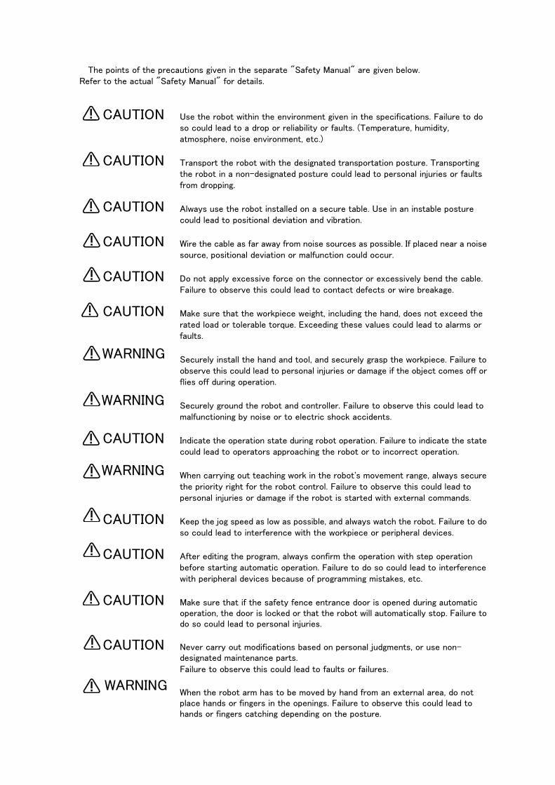
The points of the precautions given in the separate "Safety Manual" are given below.Refer to the actual "Safety Manual" for details.
Use the robot within the environment given in the specifications. Failure to do so could lead to a drop or reliability or faults. (Temperature, humidity, atmosphere, noise environment, etc.)
Transport the robot with the designated transportation posture. Transporting the robot in a non-designated posture could lead to personal injuries or faults from dropping.
Always use the robot installed on a secure table. Use in an instable posture could lead to positional deviation and vibration.
Wire the cable as far away from noise sources as possible. If placed near a noise source, positional deviation or malfunction could occur.
Do not apply excessive force on the connector or excessively bend the cable. Failure to observe this could lead to contact defects or wire breakage.
Make sure that the workpiece weight, including the hand, does not exceed the rated load or tolerable torque. Exceeding these values could lead to alarms or faults.
Securely install the hand and tool, and securely grasp the workpiece. Failure to observe this could lead to personal injuries or damage if the object comes off or flies off during operation.
Securely ground the robot and controller. Failure to observe this could lead to malfunctioning by noise or to electric shock accidents.
Indicate the operation state during robot operation. Failure to indicate the state could lead to operators approaching the robot or to incorrect operation.
When carrying out teaching work in the robot's movement range, always secure the priority right for the robot control. Failure to observe this could lead to personal injuries or damage if the robot is started with external commands.
Keep the jog speed as low as possible, and always watch the robot. Failure to do so could lead to interference with the workpiece or peripheral devices.
After editing the program, always confirm the operation with step operation before starting automatic operation. Failure to do so could lead to interference with peripheral devices because of programming mistakes, etc.
Make sure that if the safety fence entrance door is opened during automatic operation, the door is locked or that the robot will automatically stop. Failure to do so could lead to personal injuries.
Never carry out modifications based on personal judgments, or use non-designated maintenance parts. Failure to observe this could lead to faults or failures.
When the robot arm has to be moved by hand from an external area, do not place hands or fingers in the openings. Failure to observe this could lead to hands or fingers catching depending on the posture.
CAUTION
CAUTION
CAUTION
CAUTION
CAUTION
CAUTION
WARNING
WARNING
CAUTION
WARNING
CAUTION
CAUTION
CAUTION
CAUTION
WARNING

Do not stop the robot or apply emergency stop by turning the robot controller's main power OFF. If the robot controller main power is turned OFF during automatic operation, the robot accuracy could be adversely affected. Moreover, it may interfere with the peripheral device by drop or move by inertia of the arm.
Do not turn off the main power to the robot controller while rewriting the internal information of the robot controller such as the program or parameters.
If the main power to the robot controller is turned off while in automatic operation or rewriting the program or parameters, the internal information of the robot controller may be damaged.
Use the network equipments (personal computer, USB hub, LAN hub, etc) confirmed by manufacturer. The thing unsuitable for the FA environment (related with conformity, temperature or noise) exists in the equipments connected to USB. When using network equipment, measures against the noise, such as measures against EMI and the addition of the ferrite core, may be necessary. Please fully confirm the operation by customer. Guarantee and maintenance of the equipment on the market (usual office automation equipment) cannot be performed.
CAUTION
CAUTION
CAUTION
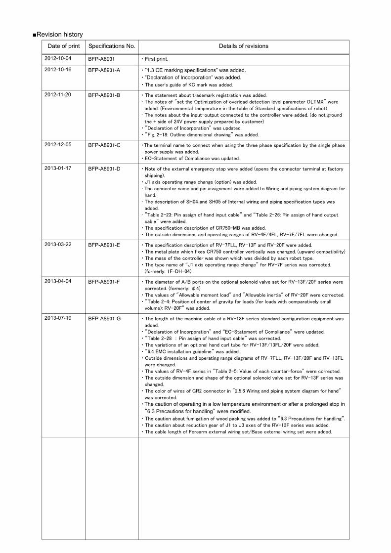
■Revision history
Date of print Specifications No. Details of revisions
2012-10-04 BFP-A8931 ・ First print.
2012-10-16 BFP-A8931-A ・ ”1.3 CE marking specifications” was added.・ ”Declaration of Incorporation” was added.・ The user's guide of KC mark was added.
2012-11-20 BFP-A8931-B ・ The statement about trademark registration was added.
・ The notes of "set the Optimization of overload detection level parameter OLTMX" were
added. (Environmental temperature in the table of Standard specifications of robot)
・ The notes about the input-output connected to the controller were added. (do not ground
the + side of 24V power supply prepared by customer)
・ ”Declaration of Incorporation” was updated.
・ ”Fig. 2-18: Outline dimensional drawing” was added.
2012-12-05 BFP-A8931-C ・The terminal name to connect when using the three phase specification by the single phase
power supply was added.
・ EC-Statement of Compliance was updated.
2013-01-17 BFP-A8931-D ・ Note of the external emergency stop were added (opens the connector terminal at factory
shipping).
・ J1 axis operating range change (option) was added.
・ The connector name and pin assignment were added to Wiring and piping system diagram for
hand.
・ The description of SH04 and SH05 of Internal wiring and piping specification types was
added.
・ ”Table 2-23: Pin assign of hand input cable” and “Table 2-26: Pin assign of hand output
cable” were added.
・ The specification description of CR750-MB was added.
・ The outside dimensions and operating ranges of RV-4F/4FL, RV-7F/7FL were changed.
2013-03-22 BFP-A8931-E ・ The specification description of RV-7FLL, RV-13F and RV-20F were added.
・ The metal plate which fixes CR750 controller vertically was changed. (upward compatibility)
・ The mass of the controller was shown which was divided by each robot type.
・ The type name of “J1 axis operating range change” for RV-7F series was corrected.
(formerly: 1F-DH-04)
2013-04-04 BFP-A8931-F ・ The diameter of A/B ports on the optional solenoid valve set for RV-13F/20F series were
corrected. (formerly: φ4)
・ The values of "Allowable moment load" and "Allowable inertia" of RV-20F were corrected.
・ ”Table 2-4: Position of center of gravity for loads (for loads with comparatively small
volume): RV-20F” was added.
2013-07-19 BFP-A8931-G ・ The length of the machine cable of a RV-13F series standard configuration equipment was
added.
・ ”Declaration of Incorporation” and “EC-Statement of Compliance” were updated.
・ ”Table 2-28 : Pin assign of hand input cable” was corrected.
・ The variations of an optional hand curl tube for RV-13F/13FL/20F were added.
・ ”6.4 EMC installation guideline” was added.
・ Outside dimensions and operating range diagrams of RV-7FLL, RV-13F/20F and RV-13FL
were changed.
・ The values of RV-4F series in "Table 2-5: Value of each counter-force" were corrected.
・ The outside dimension and shape of the optional solenoid valve set for RV-13F series was
changed.
・ The color of wires of GR2 connector in "2.5.6 Wiring and piping system diagram for hand"
was corrected.
・ The caution of operating in a low temperature environment or after a prolonged stop in
”6.3 Precautions for handling” were modified.・ The caution about fumigation of wood packing was added to ”6.3 Precautions for handling”.
・ The caution about reduction gear of J1 to J3 axes of the RV-13F series was added.
・ The cable length of Forearm external wiring set/Base external wiring set were added.

■ Introduction
This series is a full-scale industrial vertical multi-joint type robot that is designed for use in machining processes and assembling. This series supports varied environments, offering a variety of specifications including clean specification, oil mist specification and long-arm specification.
However, to comply with the target application, a work system having a well-balanced robot arm, periph-eral devices or robot and hand section must be structured.
When creating these standard specifications, we have edited them so that the Mitsubishi robot's charac-teristics and specifications can be easily understood by users considering the implementation of robots. However, if there are any unclear points, please contact your nearest Mitsubishi branch or dealer.
Mitsubishi hopes that you will consider these standard specifications and use our robots.
Note that in this specification document the specifications related to the robot arm is described Page 10, "2 Robot arm", the specifications related to the controllerPage 78, "3 Controller", and software functions and a command list Page 135, "4 Software" separately.
This document has indicated the specification of the following types robot.
*RV-4F-D/RV-4FL-D (CR750-D controller) seriesNote) Indicates it as RV-4F series.
*RV-7F-D/RV-7FL-D (CR750-D controller) seriesNote) Indicates it as RV-7F series.
*RV-7FLL-D (CR750-D controller) series *1)
*RV-13F-D (CR750-D controller) series *1)
*RV-20F-D (CR750-D controller) series *1)
Note) *1) Indicates it as "RV-13F series" for a general name of these robots.
・ No part of this manual may be reproduced by any means or in any form, without prior consent fromMitsubishi.
・ The contents of this manual are subject to change without notice.・ The specifications values are based on Mitsubishi standard testing methods.・ The information contained in this document has been written to be accurate as much as possible.
Please interpret that items not described in this document "cannot be performed." or "alarmmay occur". Please contact your nearest dealer if you find any doubtful, wrong or skipped point.
・ This specifications is original.・ Microsoft, Windows, Microsoft Windows NT are either registered trademarks or trademarks of
Microsoft Corporation in the United States and/or other countries.・ The ETHERNET is a registered trademark of the Xerox Corp. ・All other company names and production names in this document are the trademarks or registered
trademarks of their respective owners.
Copyright(C) 2012-2013 MITSUBISHI ELECTRIC CORPORATION
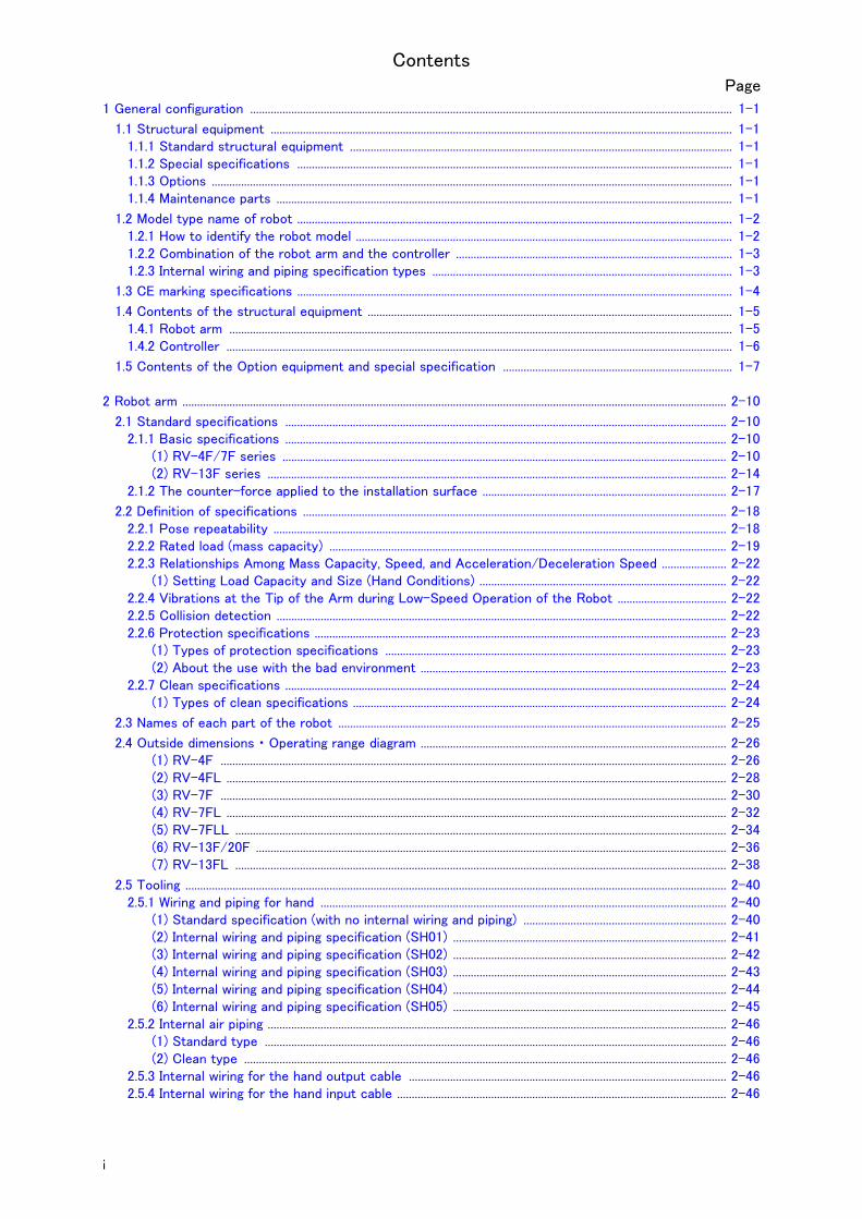
Contents
i
Page
1 General configuration .................................................................................................................................................................... 1-1
1.1 Structural equipment ............................................................................................................................................................. 1-11.1.1 Standard structural equipment .................................................................................................................................. 1-11.1.2 Special specifications .................................................................................................................................................... 1-11.1.3 Options ................................................................................................................................................................................. 1-11.1.4 Maintenance parts ........................................................................................................................................................... 1-1
1.2 Model type name of robot .................................................................................................................................................... 1-21.2.1 How to identify the robot model ................................................................................................................................ 1-21.2.2 Combination of the robot arm and the controller .............................................................................................. 1-31.2.3 Internal wiring and piping specification types ...................................................................................................... 1-3
1.3 CE marking specifications .................................................................................................................................................... 1-4
1.4 Contents of the structural equipment ............................................................................................................................ 1-51.4.1 Robot arm ........................................................................................................................................................................... 1-51.4.2 Controller ............................................................................................................................................................................ 1-6
1.5 Contents of the Option equipment and special specification .............................................................................. 1-7
2 Robot arm ......................................................................................................................................................................................... 2-10
2.1 Standard specifications ...................................................................................................................................................... 2-102.1.1 Basic specifications ...................................................................................................................................................... 2-10
(1) RV-4F/7F series ....................................................................................................................................................... 2-10(2) RV-13F series ............................................................................................................................................................ 2-14
2.1.2 The counter-force applied to the installation surface ................................................................................... 2-17
2.2 Definition of specifications ................................................................................................................................................ 2-182.2.1 Pose repeatability .......................................................................................................................................................... 2-182.2.2 Rated load (mass capacity) ....................................................................................................................................... 2-192.2.3 Relationships Among Mass Capacity, Speed, and Acceleration/Deceleration Speed ...................... 2-22
(1) Setting Load Capacity and Size (Hand Conditions) .................................................................................... 2-222.2.4 Vibrations at the Tip of the Arm during Low-Speed Operation of the Robot ..................................... 2-222.2.5 Collision detection ......................................................................................................................................................... 2-222.2.6 Protection specifications ............................................................................................................................................ 2-23
(1) Types of protection specifications .................................................................................................................... 2-23(2) About the use with the bad environment ........................................................................................................ 2-23
2.2.7 Clean specifications ...................................................................................................................................................... 2-24(1) Types of clean specifications ............................................................................................................................... 2-24
2.3 Names of each part of the robot .................................................................................................................................... 2-25
2.4 Outside dimensions ・ Operating range diagram ........................................................................................................ 2-26(1) RV-4F ............................................................................................................................................................................ 2-26(2) RV-4FL .......................................................................................................................................................................... 2-28(3) RV-7F ............................................................................................................................................................................ 2-30(4) RV-7FL .......................................................................................................................................................................... 2-32(5) RV-7FLL ....................................................................................................................................................................... 2-34(6) RV-13F/20F ................................................................................................................................................................ 2-36(7) RV-13FL ....................................................................................................................................................................... 2-38
2.5 Tooling ........................................................................................................................................................................................ 2-402.5.1 Wiring and piping for hand .......................................................................................................................................... 2-40
(1) Standard specification (with no internal wiring and piping) ..................................................................... 2-40(2) Internal wiring and piping specification (SH01) ............................................................................................. 2-41(3) Internal wiring and piping specification (SH02) ............................................................................................. 2-42(4) Internal wiring and piping specification (SH03) ............................................................................................. 2-43(5) Internal wiring and piping specification (SH04) ............................................................................................. 2-44(6) Internal wiring and piping specification (SH05) ............................................................................................. 2-45
2.5.2 Internal air piping ............................................................................................................................................................ 2-46(1) Standard type ............................................................................................................................................................. 2-46(2) Clean type .................................................................................................................................................................... 2-46
2.5.3 Internal wiring for the hand output cable ............................................................................................................ 2-462.5.4 Internal wiring for the hand input cable ................................................................................................................ 2-46

Contents
ii
Page
2.5.5 Ethernet cable, option wiring cable ........................................................................................................................ 2-462.5.6 Wiring and piping system diagram for hand ......................................................................................................... 2-47
(1) Standard specification (with no internal wiring and piping) ..................................................................... 2-47(2) Internal wiring and piping specification (SH01) ............................................................................................. 2-48(3) Internal wiring and piping specification (SH02) ............................................................................................. 2-49(4) Internal wiring and piping specification (SH03) ............................................................................................. 2-50(5) Internal wiring and piping specification (SH04) ............................................................................................. 2-51(6) Internal wiring and piping specification (SH05) ............................................................................................. 2-52
2.5.7 Electrical specifications of hand input/output .................................................................................................. 2-532.5.8 Air supply circuit example for the hand ............................................................................................................... 2-54
2.6 Shipping special specifications, options, and maintenance parts ...................................................................... 2-552.6.1 Shipping special specifications ................................................................................................................................. 2-55
(1) Machine cable ............................................................................................................................................................. 2-56
2.7 Options ....................................................................................................................................................................................... 2-57(1) Machine cable extension ........................................................................................................................................ 2-58(2) J1 axis operating range change ........................................................................................................................... 2-60(3) Solenoid valve set ..................................................................................................................................................... 2-66(4) Hand input cable ........................................................................................................................................................ 2-69(5) Hand output cable ..................................................................................................................................................... 2-70(6) Hand curl tube ............................................................................................................................................................ 2-71(7) Forearm external wiring set/ Base external wiring set ............................................................................. 2-73
2.8 About Overhaul ...................................................................................................................................................................... 2-76
2.9 Maintenance parts ................................................................................................................................................................. 2-77
3 Controller .......................................................................................................................................................................................... 3-78
3.1 Standard specifications ...................................................................................................................................................... 3-78
3.2 Protection specifications and operating supply ....................................................................................................... 3-79
3.3 Names of each part .............................................................................................................................................................. 3-80
3.4 Outside dimensions/Installation dimensions .............................................................................................................. 3-823.4.1 Outside dimensions ....................................................................................................................................................... 3-823.4.2 Installation dimensions ................................................................................................................................................. 3-83
3.5 External input/output .......................................................................................................................................................... 3-853.5.1 Types .................................................................................................................................................................................. 3-85
3.6 Dedicated input/output ...................................................................................................................................................... 3-86
3.7 Emergency stop input and output etc. ......................................................................................................................... 3-893.7.1 Connection of the external emergency stop ...................................................................................................... 3-893.7.2 Special stop input (SKIP) ........................................................................................................................................... 3-943.7.3 Door switch function .................................................................................................................................................... 3-953.7.4 Enabling device function ............................................................................................................................................. 3-95
(1) When door is opening ............................................................................................................................................... 3-95(2) When door is closing ................................................................................................................................................ 3-95(3) Automatic Operation/Jog Operation/Brake Release and Necessary Switch Settings .............. 3-96
3.8 Additional Axis Function ..................................................................................................................................................... 3-973.8.1 Wiring of the Additional Axis Interface ................................................................................................................. 3-97
3.9 Magnet contactor control connector output (AXMC) for addition axes ..................................................... 3-100
3.10 Options ................................................................................................................................................................................. 3-101(1) Teaching pendant (T/B) ...................................................................................................................................... 3-102(2) Parallel I/O interface ............................................................................................................................................ 3-105(3) External I/O cable .................................................................................................................................................. 3-110(4) Parallel I/O unit ...................................................................................................................................................... 3-112(5) External I/O cable .................................................................................................................................................. 3-121(6) CC-Link interface .................................................................................................................................................. 3-123(7) Controller protection box .................................................................................................................................... 3-126(8) RT ToolBox2/RT ToolBox2 mini ...................................................................................................................... 3-131(9) Instruction Manual(bookbinding) ....................................................................................................................... 3-133
3.11 Maintenance parts ........................................................................................................................................................... 3-134

Contents
iii
Page
4 Software ......................................................................................................................................................................................... 4-135
4.1 List of commands ............................................................................................................................................................... 4-135
4.2 List of parameters .............................................................................................................................................................. 4-138
5 Instruction Manual ..................................................................................................................................................................... 5-140
5.1 The details of each instruction manuals ................................................................................................................... 5-140
6 Safety .............................................................................................................................................................................................. 6-141
6.1 Safety ...................................................................................................................................................................................... 6-1416.1.1 Self-diagnosis stop functions ................................................................................................................................ 6-1416.1.2 External input/output signals that can be used for safety protection measures ........................... 6-1426.1.3 Precautions for using robot .................................................................................................................................... 6-1426.1.4 Safety measures for automatic operation ........................................................................................................ 6-1436.1.5 Safety measures for teaching ............................................................................................................................... 6-1436.1.6 Safety measures for maintenance and inspections, etc. ........................................................................... 6-1436.1.7 Examples of safety measures ................................................................................................................................ 6-144
(1) CR750 controller .................................................................................................................................................... 6-144(2) External emergency stop connection [supplementary explanation] ................................................. 6-149
6.2 Working environment ......................................................................................................................................................... 6-151
6.3 Precautions for handling .................................................................................................................................................. 6-151
6.4 EMC installation guideline ............................................................................................................................................... 6-1536.4.1 Outlines ........................................................................................................................................................................... 6-1536.4.2 EMC directive ............................................................................................................................................................... 6-1536.4.3 EMC measures ............................................................................................................................................................. 6-1546.4.4 Component parts for EMC measures ................................................................................................................. 6-154
(1) Ferrite core ............................................................................................................................................................... 6-154(2) Line noise filter ....................................................................................................................................................... 6-154
7Appendix ........................................................................................................................................................................... Appendix-155Appendix 1 : Specifications discussion material (RV-4F/7F series) ................................................. Appendix-155Appendix 2 : Specifications discussion material (RV-7FLL) ................................................................. Appendix-156Appendix 3 : Specifications discussion material (RV-13F/13FL) ....................................................... Appendix-157Appendix 4 : Specifications discussion material (RV-20F) ................................................................... Appendix-158
1General configuration
Structural equipment 1-1
1 General configuration
1.1 Structural equipment
Structural equipment consists of the following types.
1.1.1 Standard structural equipmentThe following items are enclosed as a standard.
(1) Robot arm (2) Controller(3) Machine cable(4) Robot arm installation bolts(5) Safety manual, CD-ROM (Instruction manual)(6) Guarantee card
1.1.2 Special specificationsFor the special specifications, some standard configuration equipment and specifications have to be changed before factory shipping. Confirm the delivery date and specify the special specifications at the order.
1.1.3 OptionsUser can install options after their delivery.
1.1.4 Maintenance partsMaterials and parts for the maintenance use.
1-2 Model type name of robot
1General configuration
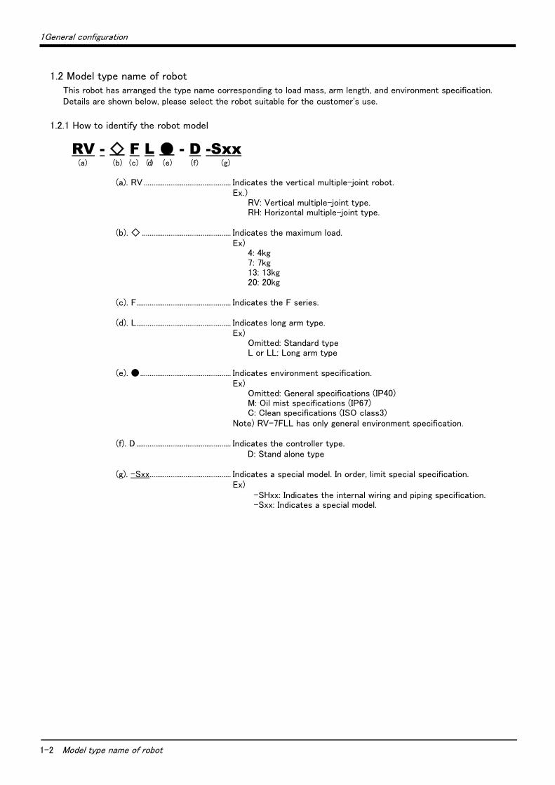
1.2 Model type name of robotThis robot has arranged the type name corresponding to load mass, arm length, and environment specification. Details are shown below, please select the robot suitable for the customer's use.
1.2.1 How to identify the robot model
RV - ◇ F L ● - D -Sxx(a) (b) (c) (d) (e) (f) (g)
(a). RV .............................................. Indicates the vertical multiple-joint robot.Ex.)
RV: Vertical multiple-joint type.RH: Horizontal multiple-joint type.
(b). ◇ ............................................... Indicates the maximum load.Ex)
4: 4kg7: 7kg13: 13kg20: 20kg
(c). F.................................................. Indicates the F series.
(d). L.................................................. Indicates long arm type.Ex)
Omitted: Standard typeL or LL: Long arm type
(e). ●................................................ Indicates environment specification.Ex)
Omitted: General specifications (IP40)M: Oil mist specifications (IP67)C: Clean specifications (ISO class3)
Note) RV-7FLL has only general environment specification.
(f). D .................................................. Indicates the controller type.D: Stand alone type
(g). -Sxx........................................... Indicates a special model. In order, limit special specification.Ex)
-SHxx: Indicates the internal wiring and piping specification.-Sxx: Indicates a special model.
1General configuration
Model type name of robot 1-3
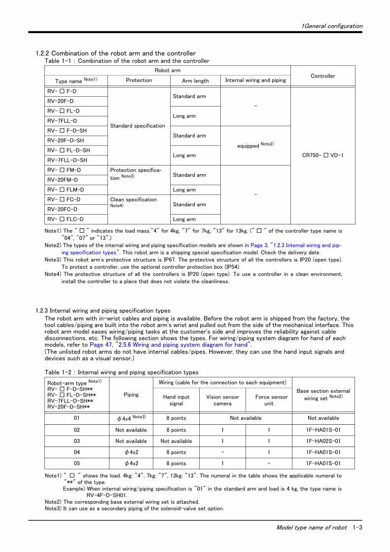
1.2.2 Combination of the robot arm and the controllerTable 1-1 : Combination of the robot arm and the controller
1.2.3 Internal wiring and piping specification typesThe robot arm with in-wrist cables and piping is available. Before the robot arm is shipped from the factory, the tool cables/piping are built into the robot arm's wrist and pulled out from the side of the mechanical interface. This robot arm model eases wiring/piping tasks at the customer's side and improves the reliability against cable disconnections, etc. The following section shows the types. For wiring/piping system diagram for hand of each models, refer to Page 47, "2.5.6 Wiring and piping system diagram for hand".(The unlisted robot arms do not have internal cables/pipes. However, they can use the hand input signals and devices such as a visual sensor.)
Table 1-2 : Internal wiring and piping specification types
Robot armController
Type name Note1)
Note1) The " □ " indicates the load mass."4" for 4kg, "7" for 7kg, "13" for 13kg. (" □ " of the controller type name is"04", "07" or "13".)
Protection Arm length Internal wiring and piping
RV- □ F-D
Standard specification
Standard arm
-
CR750- □ VD-1
RV-20F-D
RV- □ FL-DLong arm
RV-7FLL-D
RV- □ F-D-SHStandard arm
equipped Note2)
Note2) The types of the internal wiring and piping specification models are shown in Page 3, "1.2.3 Internal wiring and pip-ing specification types". This robot arm is a shipping special specification model. Check the delivery date.
RV-20F-D-SH
RV- □ FL-D-SHLong arm
RV-7FLL-D-SH
RV- □ FM-D Protection specifica-
tion Note3)
Note3) This robot arm's protective structure is IP67. The protective structure of all the controllers is IP20 (open type).To protect a controller, use the optional controller protection box (IP54).
Standard arm
-
RV-20FM-D
RV- □ FLM-D Long arm
RV- □ FC-D Clean specification Note4)
Note4) The protective structure of all the controllers is IP20 (open type). To use a controller in a clean environment,install the controller to a place that does not violate the cleanliness.
Standard armRV-20FC-D
RV- □ FLC-D Long arm
Robot-arm type Note1)
RV- □ F-D-SH**RV- □ FL-D-SH**RV-7FLL-D-SH**RV-20F-D-SH**
Note1) " □ " shows the load. 4kg: "4", 7kg: "7", 13kg: "13". The numeral in the table shows the applicable numeral to"**" of the type.Example) When internal wiring/piping specification is "01" in the standard arm and load is 4 kg, the type name is
RV-4F-D-SH01.
Piping
Wiring (cable for the connection to each equipment)
Base section external
wiring set Note2)
Note2) The corresponding base external wiring set is attached.
Hand input signal
Vision sensor camera
Force sensor unit
01 φ4x4 Note3)
Note3) It can use as a secondary piping of the solenoid-valve set option.
8 points Not available Not available
02 Not available 8 points 1 1 1F-HA01S-01
03 Not available Not available 1 1 1F-HA02S-01
04 φ4x2 8 points - 1 1F-HA01S-01
05 φ4x2 8 points 1 - 1F-HA01S-01

1-4 CE marking specifications
1General configuration
1.3 CE marking specificationsThe robot shown in the Table 1-3 is the CE Marking specification.
Table 1-3 : Robot models with CE marking specifications
Note 1) " □ " shows the load. 4kg: "04", 7kg: "07", 13kg: "13".Note 2) "xx" shows the number of the special specification.
Robot type Controller External signal logic Language setting
RV- □ F-D1-S15
RV- □ FL-D1-S15
RV- □ FM-D1-S15
RV- □ FLM-D1-S15
RV- □ FC-D1-S15
RV- □ FLC-D1-S15
CR750- □ VD1-1-S15
Source type English (ENG)RV- □ F-D1-SH15xx
RV- □ FL-D1-SH15xxCR750- □ VD1-1-S15xx
RV-7FLL-D1-S15 CR750-07VLD1-1-S15
RV-20F-D1-S15
RV-20FM-D1-S15
RV-20FC-D1-S15
CR750-20VD1-1-S15
RV-20F-D1-SH15xx CR750-20VD1-1-S15xx
Contents of the structural equipment 1-5
1.4 Contents of the structural equipment
1.4.1 Robot armThe list of structural equipment is shown in below.
Fig.1-1 : Structural equipment (Robot arm)
Pulled out from robot arm・ Forearm external wiring set/ Base
external wiring set
Forearm
Option attachment positions
Base(Opposite side)
*The figure is an example.
Hand curl tubeRV-4F/7F series, RV-7FLL・ 1E-ST040*C (1 - 4 set)
RV-13F/13FL/20F・ 1N-ST060*C (1 - 4 set)
Note) "*" differs by 1 - 4 set. Refer to Table 1-4 for details.
Machine cable extension・ Fixed type: 1S- □□ CBL-01
・ Flexed type: 1S- □□ LCBL-01
Note1) □□ refer the length.Refer to Table 1-4 for details.
Note2) Extend by adding to the arm side of the standard accessory cable (for fix-ing).
Vertical six-axis multiple-jointed type
(RV-4F-D/4FL-D、RV-7F-D/7FL-D)
Vertical six-axis multiple-jointed type
(RV-13F-D/13FL-D,RV-7FLL-D/RV-20F-D)
Either one
Machine cable(Fixed type: 2m)・ 1S-02UCBL-01
Solenoid valve set(Special hand output cable is attached)<Sink type/Source type>・ 1 set: 1F-VD01-**/1F-VD01E-**・ 2 set: 1F-VD02-**/1F-VD02E-**・ 3 set: 1F-VD03-**/1F-VD03E-**・ 4 set: 1F-VD04-**/1F-VD04E-**
Note) "**" differs by robot arm. Refer to Table 1-4 for details.
1F-VD04-02 1F-VD04-03
Internal wiring and piping specification
The robot of the factory-shipments special specification which equipped the inside of the wrist with wiring and the piping, and was pulled out from the mechanical interface
Refer to Page 3, "1.2.3 Internal wiring and piping specification
types" for details.
J1 axis operating range change(Stopper parts)・ RV-4F series: 1F-DH-03・ RV-7F series: 1F-DH-04・ RV-13F series: 1F-DH-05J1
* Installed by customer.
Hand output cable・ 1F-GR35S-02
Hand input cable・ 1F-HC35S-02
[Caution]Standard configuration
Special specifications
Option
equipment
Prepared by customer
Pneum
atic
han
d cust
om
er-
man
ufa
ctu
red
part
s
Machine cableFixed type: RV-4F/7F series..................... 5m
RV-13F series........................... 7m

1-6
1 General configuration
1.4.2 ControllerThe devices shown below can be installed on the controller.
The controllers that can be connected differ depending on the specification of the robot. (Refer to Page 2, "1.2 Model type name of robot".)
Fig.1-2 : Structural equipment
Personal computerPrepared by customer
*)Refer to Table 1-5 for USB cable.
Parallel I/O interface2D-TZ368(Sink)/2D-TZ378(Source)
CC-Link interface 2D-TZ576
Teaching pendant (T/B)
R56TB
R32TB
Controller・ RV-4F : CR750-04VD-1・ RV-7F : CR750-07VD-1・ RV-7FLL : CR750-07VLD-1・ RV-13F : CR750-13VD-1・ RV-20F : CR750-20VD-1
External I/O cable・ 2D-CBL05 (5m)・ 2D-CBL15 (15m)
Parallel I/O unit2A-RZ361(Sink)/2A-RZ371(Source)
External I/O cable・ 2A-CBL05 (5m)・ 2A-CBL15 (15m)
PLC(Programmable Logic Controller)External device
Prepared by customer
Controller protection box・ CR750-MB
Instruction Manual(bookbinding)・ RV-4F-D/7F-D/13F-D:
5F-FF01-PE01
Standard configuration
Special specifications
Options
Prepared by customer
[Caution]
equipment
The photograph is the image figure.
RT ToolBox2/RT ToolBox2 miniRT ToolBox2・ 3D-11C-WINE(CD-ROM)
(MS-Windows2000/XP/Vista/7)
RT ToolBox2 mini ・ 3D-12C-WINE(CD-ROM)
(MS-Windows2000/XP/Vista/7)

1 General configuration
Contents of the Option equipment and special specification 1-7
1.5 Contents of the Option equipment and special specification
A list of all Optional equipment and special specifications are shown below.
Table 1-4 : The list of Option equipment and special specification
Item Type Specifications Classification
Note1) Description
Internal wiring and piping
specification
(robot arm)
RV- □ F-D-SH01
RV- □ FL-D-SH01
RV-7FLL-D-SH01
RV-20F-D-SH01
Functions equipped inside of wrist:Air-hose φ4 x 4, Eight hand input signals. ○
RV- □ F-D-SH02
RV- □ FL-D-SH02
RV-7FLL-D-SH02
RV-20F-D-SH02
Functions equipped inside of wrist:Eight hand input signals, connec-tion cable for vision-sensor cam-era, connection cable for force sensor unit.
○
The connection with the force sensor unit
uses the attached adapter cable in the
force-sensor option.
Note) The corresponding base external
wiring set is attached.RV- □ F-D-SH03
RV- □ FL-D-SH03
RV-7FLL-D-SH03
RV-20F-D-SH03
Functions equipped inside of wrist:Connection cable for vision-sen-sor camera and force sensor unit. ○
RV- □ F-D-SH04
RV- □ FL-D-SH04
RV-7FLL-D-SH04
RV-20F-D-SH04
Functions equipped inside of wrist:Air-hose φ4 x 2, Eight hand input signals, connection cable for force sensor unit.
○
RV- □ F-D-SH05
RV- □ FL-D-SH05
RV-7FLL-D-SH05
RV-20F-D-SH05
Functions equipped inside of wrist:Air-hose φ4 x 2, Eight hand input signals, connection cable for vision-sensor camera.
○
J1 axis operating range change
1F-DH-03 Stopper part for RV-4F series:
Sets as the + side/- side each by
the combination within 30, 73, 103
and 146.
○
This must be installed and setting the
parameter by the customer.
* Refer to Page 60, "(2) J1 axis
operating range change" for details.
1F-DH-04 Stopper part for RV-7F series:
Sets as the + side/- side each by
the combination within 35, 77, 99
and 141.
○
1F-DH-05J1 Stopper part for RV-13F series:
Sets as the + side/- side each by
the combination within 30, 73, 103
and 146.
○
Machine cable (Replaced to shorter cable)
1S-02UCBL-01 For fixing(Set of power and signal) ○ ・ □ 2m (A 2m cable is supplied instead of
the supplied standard cable.)
Extended machine cable 1S- □□ CBL-01 For fixing(Set of power and signal) ○ 5, 10, 15m
1S- □□ LCBL-01 For flexing(Set of power and signal) ○ 5, 10, 15m
Solenoid valve set 1F-VD01-02/VD01E-02 1 set (Sink type)/(Source type) ○ The solenoid-valve set for the hand of
the customer setup.
Use for RV-4F/7F series and RV-7FLL.1F-VD02-02/VD02E-02 2 set (Sink type)/(Source type) ○
1F-VD03-02/VD03E-02 3 set (Sink type)/(Source type) ○
1F-VD04-02/VD04E-02 4 set (Sink type)/(Source type) ○
1F-VD01-03/VD01E-03 1 set (Sink type)/(Source type) ○ The solenoid-valve set for the hand of
the customer setup.
Use for RV-13F/13FL and RV-20F.1F-VD02-03/VD02E-03 2 set (Sink type)/(Source type) ○
1F-VD03-03/VD03E-03 3 set (Sink type)/(Source type) ○
1F-VD04-03/VD04E-03 4 set (Sink type)/(Source type) ○
Hand input cable 1F-HC35S-02 Robot side: connector.Hand side: wire. ○ The cable is connected to the sensor by
the customer.
Hand output cable 1F-GR35S-02 Robot side: connector.Hand side: wire ○
This cable can be used for the solenoid
valve prepared by the customer.
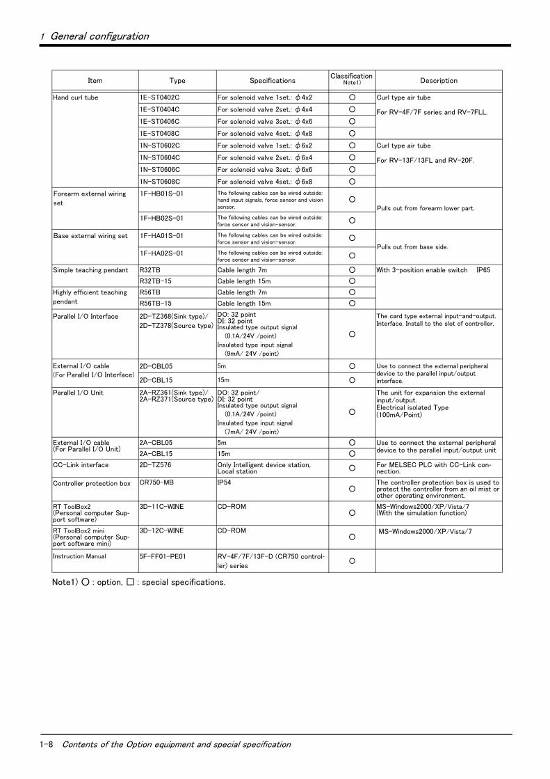
1-8 Contents of the Option equipment and special specification
1 General configuration
Hand curl tube 1E-ST0402C For solenoid valve 1set.: φ4x2 ○ Curl type air tube
For RV-4F/7F series and RV-7FLL.1E-ST0404C For solenoid valve 2set.: φ4x4 ○
1E-ST0406C For solenoid valve 3set.: φ4x6 ○
1E-ST0408C For solenoid valve 4set.: φ4x8 ○
1N-ST0602C For solenoid valve 1set.: φ6x2 ○ Curl type air tube
For RV-13F/13FL and RV-20F.1N-ST0604C For solenoid valve 2set.: φ6x4 ○
1N-ST0606C For solenoid valve 3set.: φ6x6 ○
1N-ST0608C For solenoid valve 4set.: φ6x8 ○
Forearm external wiring
set
1F-HB01S-01 The following cables can be wired outside: hand input signals, force sensor and vision sensor.
○Pulls out from forearm lower part.
1F-HB02S-01 The following cables can be wired outside: force sensor and vision-sensor.
○
Base external wiring set 1F-HA01S-01 The following cables can be wired outside:force sensor and vision-sensor.
○Pulls out from base side.
1F-HA02S-01 The following cables can be wired outside: force sensor and vision-sensor.
○
Simple teaching pendant R32TB Cable length 7m ○ With 3-position enable switch IP65
R32TB-15 Cable length 15m ○
Highly efficient teaching
pendant
R56TB Cable length 7m ○
R56TB-15 Cable length 15m ○
Parallel I/O Interface 2D-TZ368(Sink type)/
2D-TZ378(Source type)
DO: 32 pointDI: 32 pointInsulated type output signal
(0.1A/24V /point)
Insulated type input signal
(9mA/ 24V /point)
○
The card type external input-and-output. Interface. Install to the slot of controller.
External I/O cable
(For Parallel I/O Interface)2D-CBL05 5m ○ Use to connect the external peripheral
device to the parallel input/output interface.2D-CBL15 15m ○
Parallel I/O Unit 2A-RZ361(Sink type)/2A-RZ371(Source type)
DO: 32 point/DI: 32 pointInsulated type output signal
(0.1A/24V /point)
Insulated type input signal
(7mA/ 24V /point)
○
The unit for expansion the external input/output.Electrical isolated Type(100mA/Point)
External I/O cable (For Parallel I/O Unit)
2A-CBL05 5m ○ Use to connect the external peripheral device to the parallel input/output unit
2A-CBL15 15m ○
CC-Link interface 2D-TZ576 Only Intelligent device station, Local station ○ For MELSEC PLC with CC-Link con-
nection.
Controller protection box CR750-MB IP54○
The controller protection box is used to protect the controller from an oil mist or other operating environment.
RT ToolBox2(Personal computer Sup-port software)
3D-11C-WINE CD-ROM○
MS-Windows2000/XP/Vista/7 (With the simulation function)
RT ToolBox2 mini(Personal computer Sup-port software mini)
3D-12C-WINE CD-ROM○
MS-Windows2000/XP/Vista/7
Instruction Manual 5F-FF01-PE01 RV-4F/7F/13F-D (CR750 control-ler) series
○
Note1) ○ : option, □ : special specifications.
Item Type Specifications Classification
Note1) Description
1 General configuration
Contents of the Option equipment and special specification 1-9
[Reference]:The recommendation products of the USB cable are shown below
Table 1-5 : Recommendation article of the USB cable
Be careful to the USB cable to apply neither the static electricity nor the noise.Otherwise, it becomes the cause of malfunction.
Use the network equipments (personal computer, USB hub, LAN hub, etc) confirmed by manufacturer. The thing unsuitable for the FA environment (related with conformity, temperature or noise) exists in the equipments connected to USB. When using network equipment, measures against the noise, such as measures against EMI and the addition of the ferrite core, may be necessary. Please fully confirm the operation by customer. Guarantee and maintenance of the equipment on the market (usual office automation equipment) cannot be performed.
Name Type name Supplier
USB cable
(USB A type-USB mini B type)KU-AMB530 SANWA SUPPLY INC.
USB-M53 ELECOM CO., LTD.
GT09-C30USB-5PMITSUBISHI ELECTRIC SYSTEM & SERVICE CO.,
LTD.
MR-J3USBCBL3M MITSUBISHI ELECTRIC CO., LTD.
USB adapter
(USB B type-USB mini B type)AD-USBBFTM5M ELECOM CO., LTD.
Caution
Caution

2-10 Standard specifications
2Robot arm
2 Robot arm2.1 Standard specifications2.1.1 Basic specifications
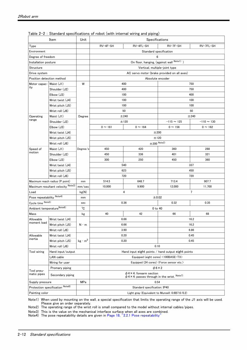
(1) RV-4F/7F seriesTable 2-1 : Standard specifications of robot (with no internal wiring and piping)
Item Unit Specifications
Type RV-4F RV-4FL RV-7F RV-7FL
Environment Omitted: Standard specificationC: Clean specificationM: Oil mist specification
Degree of freedom 6
Installation posture On floor, hanging, (against wall Note1) )
Structure Vertical, multiple-joint type
Drive system AC servo motor (brake provided on all axes)
Position detection method Absolute encoder
Motor capac-ity
Waist (J1) W 400 750
Shoulder (J2) 400 750
Elbow (J3) 100 400
Wrist twist (J4) 100 100
Wrist pitch (J5) 100 100
Wrist roll (J6) 50 50
Operatingrange
Waist (J1) Degree ±240 ±240
Shoulder (J2) ±120 -115 to 125 -110 to 130
Elbow (J3) 0 to 161 0 to 164 0 to 156 0 to 162
Wrist twist (J4) ±200
Wrist pitch (J5) ±120
Wrist roll (J6) ±360
Speed ofmotion
Waist (J1) Degree/s 450 420 360 288
Shoulder (J2) 450 336 401 321
Elbow (J3) 300 250 450 360
Wrist twist (J4) 540 337
Wrist pitch (J5) 623 450
Wrist roll (J6) 720 720
Maximum reach radius (P point) mm 514.5 648.7 713.4 907.7
Maximum resultant velocity Note2) mm/sec 9,000 11,000
Load kg(N) 4 7
Pose repeatability Note3) mm ±0.02
Cycle time Note4) sec 0.36 0.32 0.35
Ambient temperature Note5) ℃ 0 to 40
Mass kg 39 41 65 67
Allowablemoment load
Wrist twist (J4)
N ・ m
6.66 16.2
Wrist pitch (J5) 6.66 16.2
Wrist roll (J6) 3.90 6.86
Allowableinertia
Wrist twist (J4)
kg ・ m2
0.20 0.45
Wrist pitch (J5) 0.20 0.45
Wrist roll (J6) 0.10
Tool wiring Hand input/output Hand input eight points / hand output eight points
LAN cable Equipped (eight cores) <100BASE-TX>
Wiring for user Equipped (24 cores) <Force sensor etc.>
Tool pneu-matic pipes
Primary piping φ6×2
Secondary piping φ4×8
Supply pressure MPa 0.54
2Robot arm
Standard specifications 2-11
Protection specification Note6) Standard specification: IP20
Clean specification: ISO class 3 Note7)
Oil mist specification: IP67 Note8) Note9)
Painting color Light gray (Equivalent to Munsell: 0.6B7.6/0.2)
Note1) When used by mounting on the wall, a special specification that limits the operating range of the J1 axis will be used. Please give an order separately.
Note2) This is the value on the mechanical interface surface when all axes are combined.Note3) The pose repeatability details are given in Page 18, "2.2.1 Pose repeatability"Note4) The required time period to execute one cycle of the following operation pattern with 1kg load. The cycle time may be
longer depending on the required positioning accuracy for the workpiece and the operating position.
Note5) Sets the robot's operating environmental temperature as parameter OLTMX. Corresponding to the environment, the continuous control action performance and the overload-protection function are optimized. (Refers to "Optimizing the overload level" described in "Chapter 5 Functions set with parameters" of separate instruction manual/ Detailed explanations of functions and operations for details.)
Note6) The protection specification details are given in Page 23, "2.2.6 Protection specifications".Note7) The details of the clean specifications are described in Page 24, "2.2.7 Clean specifications".Note8) The protection performance cannot be ensured with some oil characteristics. Contact the dealer.Note9) If you use the controller in oil mist or similar environments, use the controller protection box to protect the controller
from the operation environment. A robot equipped with the controller protection box as standard is available.
Item Unit Specifications
300
25
2-12 Standard specifications
2Robot arm
Table 2-2 : Standard specifications of robot (with internal wiring and piping)
Item Unit Specifications
Type RV-4F-SH RV-4FL-SH RV-7F-SH RV-7FL-SH
Environment Standard specification
Degree of freedom 6
Installation posture On floor, hanging, (against wall Note1) )
Note1) When used by mounting on the wall, a special specification that limits the operating range of the J1 axis will be used. Please give an order separately.
Structure Vertical, multiple-joint type
Drive system AC servo motor (brake provided on all axes)
Position detection method Absolute encoder
Motor capac-ity
Waist (J1) W 400 750
Shoulder (J2) 400 750
Elbow (J3) 100 400
Wrist twist (J4) 100 100
Wrist pitch (J5) 100 100
Wrist roll (J6) 50 50
Operatingrange
Waist (J1) Degree ±240 ±240
Shoulder (J2) ±120 -115 ~ 125 -110 ~ 130
Elbow (J3) 0 ~ 161 0 ~ 164 0 ~ 156 0 ~ 162
Wrist twist (J4) ±200
Wrist pitch (J5) ±120
Wrist roll (J6) ±200 Note2)
Note2) The operating range of the wrist roll is small compared to the model without internal cables/pipes.
Speed ofmotion
Waist (J1) Degree/s 450 420 360 288
Shoulder (J2) 450 336 401 321
Elbow (J3) 300 250 450 360
Wrist twist (J4) 540 337
Wrist pitch (J5) 623 450
Wrist roll (J6) 720 720
Maximum reach radius (P point) mm 514.5 648.7 713.4 907.7
Maximum resultant velocity Note3)
Note3) This is the value on the mechanical interface surface when all axes are combined.
mm/sec 10,000 9,900 12,000 11,700
Load kg(N) 4 7
Pose repeatability Note4)
Note4) The pose repeatability details are given in Page 18, "2.2.1 Pose repeatability"
mm ±0.02
Cycle time Note5) sec 0.36 0.32 0.35
Ambient temperatureNote6) ℃ 0 to 40
Mass kg 40 42 66 68
Allowablemoment load
Wrist twist (J4)
N ・ m
6.66 16.2
Wrist pitch (J5) 6.66 16.2
Wrist roll (J6) 3.90 6.86
Allowableinertia
Wrist twist (J4)
kg ・ m2
0.20 0.45
Wrist pitch (J5) 0.20 0.45
Wrist roll (J6) 0.10
Tool wiring Hand input/output Hand input eight points / hand output eight points
LAN cable Equipped (eight cores) <100BASE-TX>
Wiring for user Equipped (24 cores) <Force sensor etc.>
Tool pneu-matic pipes
Promary piping φ6×2
Secondary pipingφ4×4: forearm sectionφ4×4: passes through in the wrist. Note7)
Supply pressure MPa 0.54
Protection specification Note8) Standard specification: IP40
Painting color Light gray (Equivalent to Munsell: 0.6B7.6/0.2)

2Robot arm
Standard specifications 2-13
Note5) The required time period to execute one cycle of the following operation pattern with 1kg load. The cycle time may be longer depending on the required positioning accuracy for the workpiece and the operating position.
Note6) Sets the robot's operating environmental temperature as parameter OLTMX. Corresponding to the environment, the continuous control action performance and the overload-protection function are optimized. (Refers to "Optimizing the overload level" described in "Chapter 5 Functions set with parameters" of separate instruction manual/ Detailed explanations of functions and operations for details.)
Note7) The internal wiring and piping specification is φ4x4.Note8) The protection specification details are given in Page 23, "2.2.6 Protection specifications".
300
25
2-14 Standard specifications
2Robot arm
(2) RV-13F seriesTable 2-3 : Standard specifications of robot (with no internal wiring and piping)
Item Unit Specifications
Type RV-13F RV-13FL RV-20F RV-7FLL
Environment Omitted: Standard specificationC: Clean specificationM: Oil mist specification
Standard specifica-tion
Degree of freedom 6
Installation posture On floor, hanging (against wallNote1) )
Structure Vertical, multiple-joint type
Drive system AC servo motor (brake provided on all axes)
Position detection method Absolute encoder
Motor capac-ity
Waist (J1) W 1500
Shoulder (J2) 1500
Elbow (J3) 750
Wrist twist (J4) 400
Wrist pitch (J5) 200 100
Wrist roll (J6) 100 50
Operatingrange
Waist (J1) Degree ±190
Shoulder (J2) -90 to +150
Elbow (J3) -10 to +157.5
Wrist twist (J4) ±200
Wrist pitch (J5) ±120
Wrist roll (J6) ±360
Speed ofmotion
Waist (J1) Degree/s 290 234 110 234
Shoulder (J2) 234 164 110 164
Elbow (J3) 312 219 110 219
Wrist twist (J4) 375 124 375
Wrist pitch (J5) 375 125 450
Wrist roll (J6) 720 360 720
Maximum reach radius (P point) mm 1,094 1,388 1,094 1,503
Maximum resultant velocityNote2) mm/sec 10,450 9,700 4,200 15,300
Load Rating (Maximum) kg 12(13) 15(20) 7(7)
Pose repeatabilityNote3) mm ±0.05 ±0.06
Cycle timeNote4) sec 0.53 0.68 0.70 0.63
Ambient temperatureNote5) ℃ 0 to 40
Mass kg 120 130 120 130
Allowablemoment load
Wrist twist (J4) N ・ m 19.3 49 16.2
Wrist pitch (J5) 19.3 49 16.2
Wrist roll (J6) 11 6.86
Allowableinertia
Wrist twist (J4) kg ・ m2 0.47 1.4 0.45
Wrist pitch (J5) 0.47 1.4 0.45
Wrist roll (J6) 0.14 0.1
2Robot arm
Standard specifications 2-15
Tool wiring Hand input/output Hand input eight points / hand output eight points
LAN cable Equipped (eight cores) <100BASE-TX>
Wiring for user Equipped (24 cores) <Force sensor etc.>
Tool pneu-matic pipes
Promary piping φ6×2
Secondary piping φ6×8
Supply pressure MPa 0.54
Protection specification Note6) Standard specification: IP40
Clean specification: ISO class 3 Note7)
Oil mist specification: IP67 Note8) Note9) IP40
Painting color Light gray (Equivalent to Munsell: 0.6B7.6/0.2)
Note1) When used by mounting on the wall, a special specification that limits the operating range of the J1 axis will be used. Please give an order separately.
Note2) This is the value on the mechanical interface surface when all axes are combined.Note3) The pose repeatability details are given in Page 18, "2.2.1 Pose repeatability"Note4) The required time period to execute one cycle of the following operation pattern with 5kg load. The cycle time may be
longer depending on the required positioning accuracy for the workpiece and the operating position.
Note5) Sets the robot's operating environmental temperature as parameter OLTMX. Corresponding to the environment, the continuous control action performance and the overload-protection function are optimized. (Refers to "Optimizing the overload level" described in "Chapter 5 Functions set with parameters" of separate instruction manual/ Detailed expla-nations of functions and operations for details.)
Note6) The protection specification details are given in Page 23, "2.2.6 Protection specifications".Note7) The details of the clean specifications are described in Page 24, "2.2.7 Clean specifications".Note8) The protection performance cannot be ensured with some oil characteristics. Contact the dealer.Note9) To use a controller in an oil mist environment, use the optional controller protection box and protect the controller from
oil mists.
Item Unit Specifications
300
25
2-16 Standard specifications
2Robot arm
Table 2-4 : Standard specifications of robot (with internal wiring and piping)
Item Unit Specifications
Type RV-13F-SH RV-13FL-SH RV-20F-SH RV-7FLL-SH
Environment Standard specification
Degree of freedom 6
Installation posture On floor, hanging (against wallNote1) )
Structure Vertical, multiple-joint type
Drive system AC servo motor (brake provided on all axes)
Position detection method Absolute encoder
Motor capac-ity
Waist (J1) W 1500
Shoulder (J2) 1500
Elbow (J3) 750
Wrist twist (J4) 400
Wrist pitch (J5) 200 100
Wrist roll (J6) 100 50
Operatingrange
Waist (J1) Degree ±190
Shoulder (J2) -90 to +150
Elbow (J3) -10 to +157.5
Wrist twist (J4) ±200
Wrist pitch (J5) ±120
Wrist roll (J6) ±200Note2)
Speed ofmotion
Waist (J1) Degree/s 290 234 110 234
Shoulder (J2) 234 164 110 164
Elbow (J3) 312 219 110 219
Wrist twist (J4) 375 124 375
Wrist pitch (J5) 375 125 450
Wrist roll (J6) 720 360 720
Maximum reach radius (P point) mm 1,094 1,388 1,094 1,503
Maximum resultant velocityNote3) mm/sec 10,450 9,700 4,200 15,300
Load Rating (Maximum) kg 12(13) 15(20) 7(7)
Pose repeatabilityNote4) mm ±0.05 ±0.06
Cycle timeNote5) sec 0.53 0.68 0.70 0.63
Ambient temperatureNote6) ℃ 0-40
Mass kg 120 130 120 130
Allowablemoment load
Wrist twist (J4) N ・ m 19.3 49 16.2
Wrist pitch (J5) 19.3 49 16.2
Wrist roll (J6) 11 6.86
Allowableinertia
Wrist twist (J4) kg ・ m2 0.47 1.4 0.45
Wrist pitch (J5) 0.47 1.4 0.45
Wrist roll (J6) 0.14 0.1
Tool wiring Hand input/output Hand input eight points / hand output eight points
LAN cable Equipped (eight cores) <100BASE-TX>
Wiring for user Equipped (24 cores) <Force sensor etc.>
2Robot arm
Standard specifications 2-17
2.1.2 The counter-force applied to the installation surface The counter-force applied to the installation surface for the strength design of the robot installation surface is shown.
Table 2-5 : Value of each counter-force
Tool pneu-matic pipes
Promary piping φ6×2
Secondary piping φ4×4Note7)
Supply pressure MPa 0.54
Protection specification Note8) Standard specification: IP40
Painting color Light gray (Equivalent to Munsell: 0.6B7.6/0.2)
Note1) When used by mounting on the wall, a special specification that limits the operating range of the J1 axis will be used. Please give an order separately.
Note2) The operating range of the wrist roll is small compared to the model without internal cables/pipes.Note3) This is the value on the mechanical interface surface when all axes are combined.Note4) The pose repeatability details are given in Page 18, "2.2.1 Pose repeatability"Note5) The required time period to execute one cycle of the following operation pattern with 5kg load. The cycle time may be
longer depending on the required positioning accuracy for the workpiece and the operating position.
Note6) Sets the robot's operating environmental temperature as parameter OLTMX. Corresponding to the environment, the continuous control action performance and the overload-protection function are optimized. (Refers to "Optimizing the overload level" described in "Chapter 5 Functions set with parameters" of separate instruction manual/ Detailed expla-nations of functions and operations for details.)
Note7) The internal wiring and piping specification is φ4x4.Note8) The protection specification details are given in Page 23, "2.2.6 Protection specifications".
Item UnitValue
RV-4F series RV-7F series RV-13F series
Falls moment: ML N ・ m 410 900 2,060
Torsion moment: MT N ・ m 400 900 2,060
Horizontal translation force: FH
N700 1,000 1,750
Vertical translation force: FV N 1,200 1,700 2,900
Item Unit Specifications
300
25
2-18 Definition of specifications
2 Robot arm
2.2 Definition of specifications
The accuracy of pose repeatability mentioned in catalogs and in the specification manual is defined as follows.
2.2.1 Pose repeatabilityFor this robot, the pose repeatability is given in accordance with JIS 8432 (Pose repeatability). Note that the value is based on 100 measurements (although 30 measurements are required according to JIS).
[Caution] The specified "pose repeatability" is not guaranteed to be satisfied under the following conditions.
[1] Operation pattern factors1) When an operation that approaches from different directions and orientations are included in rela-
tion to the teaching position during repeated operations
2) When the speed at teaching and the speed at execution are different
[2] Load fluctuation factor1) When work is present/absent in repeated operations
[3] Disturbance factor during operation1) Even if approaching from the same direction and orientation to the teaching position, when the
power is turned OFF or a stop operation is performed halfway
[4] Temperature factors1) When the operating environment temperature changes
2) When accuracy is required before and after a warm-up operation
[5] Factors due to differences in accuracy definition1) When accuracy is required between a position set by a numeric value in the robot's internal coor-
dinate system and a position within the actual space
2) When accuracy is required between a position generated by the pallet function and a position within the actual space

2 Robot arm
2-19
2.2.2 Rated load (mass capacity)The robot's mass capacity is expressed solely in terms of mass, but even for tools and works of similar mass, eccentric loads will have some restrictions When designing the tooling or when selecting a robot, consider the fol-lowing issues.
(1) The tooling should have the value less or equal than the smaller of the tolerable inertia and the tolerable moment found in Page 10, "2.1.1 Basic specifications".
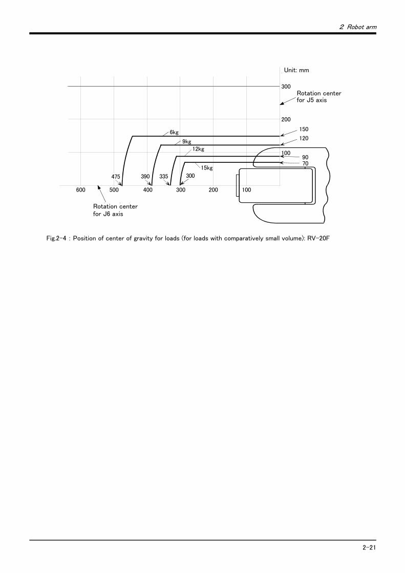
(2) Fig. 2-1, Fig. 2-2, Fig. 2-3 and Fig. 2-4 shows the distribution dimensions for the center of gravity in the case where the volume of the load is relatively small. Use this figure as a reference when designing the tooling.
(3) Even if the load is force, not the mass, design the tooling so that moment does not exceed the allowable moment. Refer to Page 10, "2.1 Standard specifications" for details of allowable moment value.
[Caution] The mass capacity is greatly influenced by the operating speed of the robot and the motion posture.Even if you are within the allowable range mentioned previously, an overload or generate an overcurrntalarm could occur. In such cases, it will be necessary to change the time setting for acceleration/deceler-ation, the operating speed, and the motion posture.
[Caution] The overhang amount of the load, such as the mass capacity and the allowable moment of inertiadefined in this section, are dynamic limit values determined by the capacity of the motor that drives axesor the capacity of the speed reducer. Therefore, it does not guarantee the accuracy on all areas of tooling.Guaranteed accuracy is measured from the center point of the mechanical interface surface. Please notethat if the point of operation is kept away from the mechanical interface surface by long and low-rigidtooling, the positioning accuracy may deteriorate or may cause vibration.
[Caution] Even within the allowable range previously mentioned, an overload alarm may be generated if an ascend-ing operation continues at a micro-low speed. In such a case, it is necessary to increase the ascendingspeed.
Fig.2-1 : Position of center of gravity for loads (for loads with comparatively small volume): RV-4F/4FL
400
200
100200300
150
100
50
0
170
J6軸回転中心
J5軸回転中心 220
155
100
1kg
225290405
2kg
3kg
4kg 120
単位 : mmUnit: mm
Rotation center for J5 axis
Rotation center for J6 axis

2-20
2 Robot arm
Fig.2-2 : Position of center of gravity for loads (for loads with comparatively small volume): RV-7F/7FL
Fig.2-3 : Position of center of gravity for loads (for loads with comparatively small volume): RV-13F/13FL
単位 : mm
600 400 300 200 100
300
200
500
100
175
155
115
135
100
240310
355
430600
220
310
J6軸回転中心
J5軸回転中心
1kg
2kg
3kg
4kg5kg6kg
7kg
280 255
Unit: mm
Rotation center for J5 axis
Rotation center for J6 axis
単位 : mm
600 400 300 200 100
300
200
500
100
210
120
90
J6軸回転中心
J5軸回転中心
3kg
6kg
9kg
12kg
215
150
390 160275
Unit: mm
Rotation center for J6 axis
Rotation center for J5 axis
2 Robot arm
2-21
Fig.2-4 : Position of center of gravity for loads (for loads with comparatively small volume): RV-20F
単位 : mm
600 400 300 200 100
300
200
500
100
120
90
J6軸回転中心
J5軸回転中心
6kg
9kg
335
150
475 300390
7015kg
12kg
Unit: mm
Rotation center for J6 axis
Rotation center for J5 axis

2-22
2 Robot arm
2.2.3 Relationships Among Mass Capacity, Speed, and Acceleration/Deceleration SpeedThis robot automatically sets the optimum acceleration and deceleration speeds and maximum speed, according to the load capacity and size that have been set, and operates using these automatically set speeds. To achieve that, it is necessary to correctly set the actual load data (mass and size of hand and work) to be used. However, vibration, overheating and errors such as excessive margin of error and overload may occur, depending on the robot operation pattern or ambient temperature.
In such a case, change the setting value to the +20% range.
If a setting is performed in such a way that it falls below the mounted load, the life span of the mechanism ele-ments used in the robot may be shortened. In the case of a work requiring a high degree of accuracy, set up the load correctly and use the robot by lowering the ratios of the acceleration and deceleration speeds.
(1) Setting Load Capacity and Size (Hand Conditions)Set up the capacity and size of the hand with the "HNDDAT*" parameter (optimum acceleration/deceleration setting parameter), and set up the capacity and size of the work with the "WRKDAT*" parameter. Numbers 0 to 8 can be used for the asterisk (*) part. Designate the "HNDDAT*" and "WRKDAT*" parameters to be used using the "LoadSet" command in a program. For more details, refer to the separate "Instruction Manual/Detailed Explanation of Functions and Operations."It is the same meaning as "LoadSet 0.0" if not using the "LoadSet".
2.2.4 Vibrations at the Tip of the Arm during Low-Speed Operation of the RobotVibrations at the tip of the arm may increase substantially during the low-speed operation of the robot, depending on the combination of robot operation, hand mass and hand inertia. This problem occurs when the vibration count specific to the robot arm and the vibration count of the arm driving force are coming close to each other. These vibrations at the tip of the arm can be reduced by taking the following measures:
1) Lower the robot's operating speed by approximately 5% from high speed using the Ovrd command.2) Change and move the teaching points of the robot.3) Change the hand mass and hand inertia.
2.2.5 Collision detectionThis series have the "collision detection function" which detects the abnormalities by the collision of the robot arm, however initial setting is in invalid condition. The enable/disable of this function can be changed by parameter: COL and command: ColChk, this function is effective for protect of the robot and of the peripheral equipment.
The abnormalities are detected by the robot's kinetics model, presuming torque necessary for movement at any time. Therefore, the setting parameter (HNDDAT*, WRKDAT*) of the hand and the work piece conditions should be right. And, it may be detected as the collision in movement as speed and motor torque are changed rapidly. (for example, the movement near the place of the origin by linear interpolation, the reversal movement, the cold con-dition, the operation after long term stoppage)
In such a case, by adjusting the value of the setting parameter (COLLVL, COLLVLJG) of the collision detection level according to actual use environment, the sensitivity of collision detection can be optimized and the damage risk can be reduced further. And, in the operation after the low temperature or long term stoppage, please operate by accustoming at low speed (warm-up), or use the warm-up operation mode.
Refer to the separate instruction manual "Detailed explanations of functions and operations" for details of related
parameter.
2 Robot arm
2-23
2.2.6 Protection specifications(1) Types of protection specifications
The robot arm has protection specifications that comply with the IEC Standards. The protection specifications and applicable fields are shown in Table 2-6. Even oil mist environment can be used in addition to the general environment.
Table 2-6 : Protection specifications and applicable fields
Use the controller protection box to protect the controller from the environment when the controller will be used in the environment such as the oil mist shown in the Table 2-6.
The IEC IP symbols define the degree of protection against solids and fluids, and do not indicate a protective structure against the entry of oil or water.
The IEC standard is described by the following "Information" And, the corrosion of the rust etc. may occur to the robot with the liquids, such as the water and the oil.
【Information】
・ The IEC IP40
The protection standard for approach in the dangerous spot in the tool. It indicates the protective structure that the proximity probe 2.5mm in diameter must not advance.
・ The IEC IP67
Protection against water infiltration as specified in IP67 indicates a protective structure that is not harmfully affected, even if the test device dives underwater for the 30 minutes. The diving depth is shown below. When the height of the test device is less than 850 mm, the position of the lowest part is 1 m from the water sur-face.
When the height of the test device is 850 mm or more, the position of the highest part is 150 mm from the water surface.
(2) About the use with the bad environmentThe robot arm with protection specification (oil mist specification) is made by order. This robot has protection methods that conform to IEC's IP67 standards (splashproof type). Recommended usage conditions.
1) The robot is designed for use in combination with machining device.2) To ensure IP67 over the warranty period and further, the inside of the robot arm needs to be pressurized.
Use the provided φ8 joint (AIR PURGE) to supply dry air for pressurizing. The φ8 joint (AIR PURGE) can be found at the base rear part of the robot arm.
Table 2-7 : Specification of the dry air for pressurization
3) We are confirming examining with the cutting oil, and satisfying protection specification. Our warranty does not cover damages or failure resulting from the robot being operated in any environment where other cutting oils than those listed in the table are used (except cutting oils with respect to which the robot's compatibil-ity with the protection specification is verified through our operability evaluation) or where the robot body
TypeProtection
specifications(IEC Standards value)
Classification Applicable field Remarks
RV-4F-D/4FL-D
RV-7F-D/7FL-D
RV-7FLL-D
RV-13F-D/13FL-D
RV-20F-D
IP40
General environ-ment specifications
General assembly
Slightly dusty environment
RV-4FM-D/4FLM-D
RV-7FM-D/7FLM-D
RV-13FM-D/13FLM-D
RV-20FM-D
IP67
Oil mist specifica-tions
Machine tool (cutting)
Machine shop with heavy oil mist
Dusty work shop
Item Dew point Pressure
Specification The atmospheric pressure dew point is -
20 degree or less.
0.01MPa or less
CAUTION
2-24
2 Robot arm
may be directly splashed with water, oil or dust in quantities larger than stated in the protection specifica-tion.
4) Take measures so that the robot will not be exposed to water, oil and/or chips for a long period of time.
Also, entrained water droplets lead to the formation of rust on the robot, but would not usually affect the robot's ability to operate normally.
The warranty is invalid for any faults that occur when the robot is used under the following conditions.
Also, if the cover and/or other parts are damaged by interferences caused by the peripheral devices and the robot, the protection specification (seal performance, etc.) may be degraded. Therefore, please pay extra attention when handling the robot.
Refer to Page 151, "6.2 Working environment".
1) In surroundings that generate inflammable gases or corrosive gasses.2) Atmosphere of the mist containing polish liquid etc.3) Atmosphere in which the water, the oil, and the dust exceeding protection specification fall on the robot arm
directly.4) Pressurization by the dry air exceeding the specification of Table 2-7.
2.2.7 Clean specifications(1) Types of clean specifications
The robot arm with clean specification is made by order. Please check the delivery schedule.
Table 2-8 : Clean specifications
■ Precautions for use1) A φ8 VACUUM coupling is provided in the base section of the robot arm for vacuum inside the robot arm.
(Refer to Fig. 2-20) When using the robot, connect this coupling with the vacuum generating valve (Refer to Table 2-9) and vacuum pump (furnished by the customer).
2) To suck in the robot arm, use the vacuum generator of the specification shown in following a) and b).a) When using the vacuum generator
Table 2-9 : Specifications of vacuum generation valve (Confirmed in our company)
b) When using the vacuum pump Assure the vacuum flow rate of more than 30 L/min. And, secure the exhaust course from the pump not to affect the power supply and the cleanness for the vacuum pumps.
Type Degree of cleanliness Internal suction Remarks
RV-4FC-D/4FLC-D
RV-7FC-D/7FLC-D
RV-13FC-D/13FLC-D
RV-20FC-D
ISO class3 Concentrated suction with vacuum
generating valve.
Use it in the clean room with the
down flow (flow velocity 0.3 m/s
above).
The use of a vacuum generating valve
is recommended.
Type Maker Air pressure Note1)
Note1) It is the vacuum pump maker's written specification.
Quantity
MEDT 14 KONEGAI CORPORATION ・ Vacuum rate: 90.0 L/min(ANR) 1
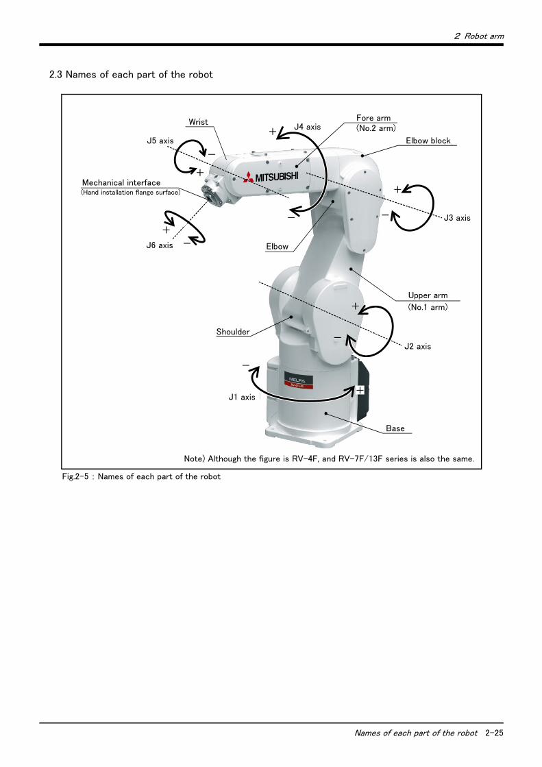
2 Robot arm
Names of each part of the robot 2-25
2.3 Names of each part of the robot
Fig.2-5 : Names of each part of the robot
ベース
ショルダ
J2軸
+
-
J3軸
+
-
アッパーアーム
エルボブロック
J4軸+
-
フォアアーム
J6軸
+
-
メカニカルインタフェース
(ハンド取付フランジ面)
J1軸
-
エルボ
リスト
J5軸
+
-
+
(No.1アーム)
(No.2アーム)
Elbow block
Fore armJ4 axis
Wrist
J5 axis
Mechanical interface(Hand installation flange surface)
J6 axis Elbow
Shoulder
J1 axis
Base
J2 axis
Upper arm
J3 axis
(No.1 arm)
(No.2 arm)
Note) Although the figure is RV-4F, and RV-7F/13F series is also the same.

2-26 Outside dimensions ・ Operating range diagram
2 Robot arm
2.4 Outside dimensions ・ Operating range diagram
(1) RV-4F
Fig.2-6 : Outside dimensions: RV-4F
Maintenance space
Approx. 100
View A: Detail of mechanical interface
φ20H7 depth 6
View B bottom view drawing: Detail of installation dimension
*2)
Notes1. *1) Ensure the cable connection space to connect machine cables.2. *2) Ensure the maintenance space to take out the cover.3. *3) The screw should go in to a depth of 7.5mm to 8mm.4. *4) Screw hole (M4 depth 8) for securing the user cables/piping.5. *5) The size of the internal wiring and piping specification model (-SHxx).6. *6) The depth is 6mm for the normal specification, 3.5mm for the clean/oil mist specification and 6.5mm for -SH**
specification.
Note) Don't install the robot arm in the position where direct rays or the heat of lighting hits. The skin temperature of the robot arm may rise, and the error may occur.
Standard specification
Clean/oil mist specification
-SH** specification
Clean/oil mist specification
-SH** specification
Cable connection space
Standard specification
Clean/oil mist specification
-SH** specification
depth 8
4-M5 screw depth 8*3)
4-φ9 installation hole
(Ins
talla
tion s
urfa
ce)
(Installation surface)
Clean/oil mist specification
-SH** specification
Minimum
Rev. A
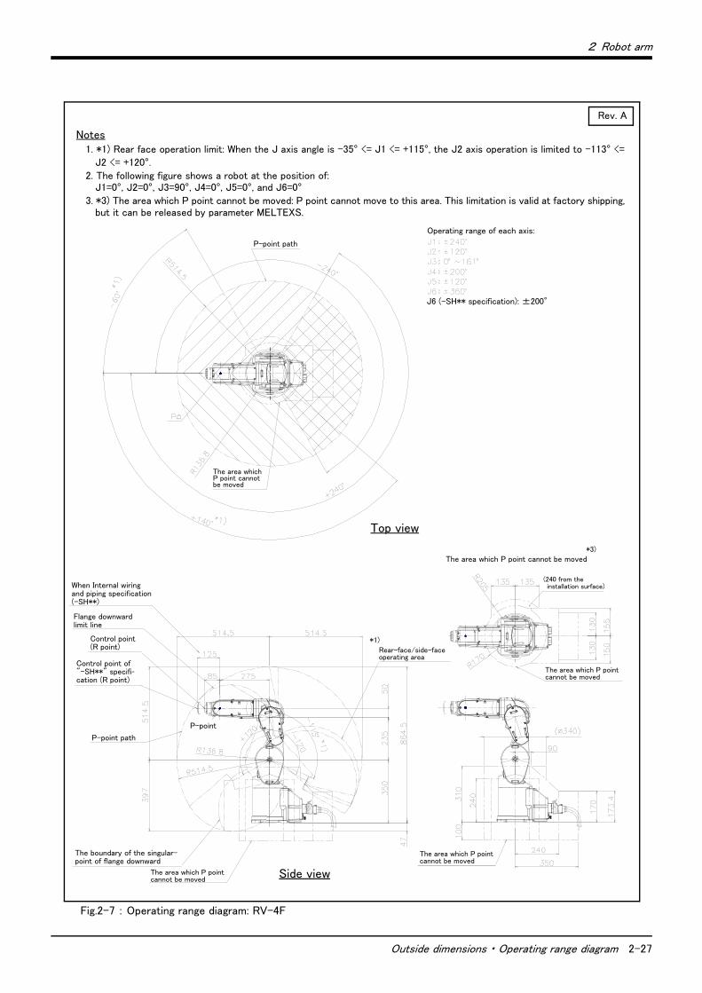
2 Robot arm
Outside dimensions ・ Operating range diagram 2-27
Fig.2-7 : Operating range diagram: RV-4F
Notes1. *1) Rear face operation limit: When the J axis angle is -35° <= J1 <= +115°, the J2 axis operation is limited to -113° <=
J2 <= +120°.2. The following figure shows a robot at the position of:
J1=0°, J2=0°, J3=90°, J4=0°, J5=0°, and J6=0°3. *3) The area which P point cannot be moved: P point cannot move to this area. This limitation is valid at factory shipping,
but it can be released by parameter MELTEXS.
Side view
Top view
When Internal wiring and piping specification (-SH**)
Flange downward limit line
Control point(R point)
Control point of "-SH**" specifi-cation (R point)
Operating range of each axis:
The boundary of the singular-point of flange downward
P-point path
P-point
J6 (-SH** specification): ±200°
P-point path
Rear-face/side-faceoperating area
*1)
Rev. A
The area which P point cannot be moved*3)
(240 from the installation surface)
The area which P point cannot be moved
The area which P point cannot be moved
The area which P point cannot be moved
The area which P point cannot be moved

2-28 Outside dimensions ・ Operating range diagram
2 Robot arm
(2) RV-4FL
Fig.2-8 : Outside dimensions: RV-4FL
Notes1. *1) Ensure the cable connection space to connect machine cables.2. *2) Ensure the maintenance space to take out the cover.3. *3) The screw should go in to a depth of 7.5mm to 8mm.4. *4) Screw hole (M4 depth 8) for securing the user cables/piping.5. *5) The size of the internal wiring and piping specification model (-SHxx).6. *6) The depth is 6mm for the normal specification, 3.5mm for the clean/oil mist specification and 6.5mm for -SH**
specification.
Note) Don't install the robot arm in the position where direct rays or the heat of lighting hits. The skin temperature of the robot arm may rise, and the error may occur.
Maintenance space
Approx. 100
View A: Detail of mechanical interface
φ20H7 depth 6
View B bottom view drawing: Detail of installation dimension
*2)
Standard specification
Clean/oil mist specification
-SH** specification
Clean/oil mist specification
-SH** specification
Cable connection space
Standard specification
Clean/oil mist specification
-SH** specification
depth 8
4-M5 screw depth 8*3)
4-φ9 installation hole
(Ins
talla
tion
surf
ace)
(Installation surface)
Clean/oil mist specification
-SH** specification
Minimum
Rev. A

2 Robot arm
Outside dimensions ・ Operating range diagram 2-29
Fig.2-9 : Operating range diagram: RV-4FL
Notes1. *1) Rear face operation limit: When the J axis angle is -35° <= J1 <= +110°, the J2 axis operation is limited to -114° <=
J2 <= +120°.2. The following figure shows a robot at the position of:
J1=0°, J2=0°, J3=90°, J4=0°, J5=0°, and J6=0°3. *3) The area which P point cannot be moved: P point cannot move to this area. This limitation is valid at factory shipping,
but it can be released by parameter MELTEXS.
Side view
Top view
When Internal wiring and piping specification (-SH**)
Flange downward limit line
Control point(R point)
Control point of "-SH**" specifi-cation (R point)
Operating range of each axis:
The boundary of the singular-point of flange downward
P-point path
P-point
J6 (-SH** specification): ±200°
P-point path
Rear-faceoperating area
*1)
Rev. A
P-point
(240 from the installation surface)
The area which P point cannot be moved
The area which P point cannot be moved
The area which P point cannot be moved
The area which P point cannot be moved*3)
The area which P point cannot be moved

2-30 Outside dimensions ・ Operating range diagram
2 Robot arm
(3) RV-7F
Fig.2-10 : Outside dimensions: RV-7F
Approx. 100
View A: Detail of mechanical interface
φ20H7 depth 6
View B bottom view drawing: Detail of installation dimension
Standard specification
Clean/oil mist specification
-SH** specification
Clean/oil mist specification
-SH** specification
Cable connection space
Standard specification
Clean/oil mist specification
-SH** specification
depth 8
4-M5 screw depth 8*3)
4-φ9 installation hole
(Inst
alla
tion
surf
ace)
(Installation surface)
Clean/oil mist specification
-SH** specification
Minimum
Rev. ANotes
1. *1) Ensure the cable connection space to connect machine cables.2. *2) Ensure the maintenance space to take out the cover.3. *3) The screw should go in to a depth of 7.5mm to 8mm.4. *4) Screw hole (M4 depth 8) for securing the user cables/piping.5. *5) The size of the internal wiring and piping specification model (-SHxx).6. *6) The depth is 6mm for the normal specification, 3.5mm for the clean/oil mist specification and 6.5mm for -SH**
specification.
Note) Don't install the robot arm in the position where direct rays or the heat of lighting hits. The skin temperature of the robot arm may rise, and the error may occur.
Maintenance space
*2)

2 Robot arm
Outside dimensions ・ Operating range diagram 2-31
Fig.2-11 : Operating range diagram: RV-7F
Notes1. The following figure shows a robot at the position of:
J1=0°, J2=0°, J3=90°, J4=0°, J5=0°, and J6=0°2. *1) The area which P point cannot be moved: P point cannot move to this area. This limitation is valid at factory shipping,
but it can be released by parameter MELTEXS.
Side view
Top view
When Internal wiring and piping specification (-SH**)
Flange downward limit line
Control point(R point)
Control point of "-SH**" specifi-cation (R point)
Operating range of each axis:
The boundary of the singular-point of flange downward
P-point path
P-point
J6 (-SH** specification): ±200°
P-point path
Rev. A
P-point
(271 from the installation surface)
The area which P point cannot be moved
The area which P point cannot be moved
The area which P point cannot be moved
The area which P point cannot be moved*1)
The area which P point cannot be moved
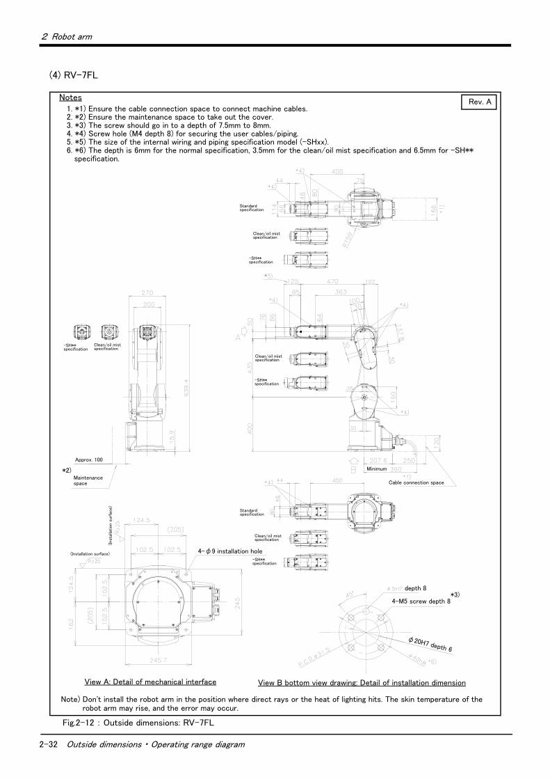
2-32 Outside dimensions ・ Operating range diagram
2 Robot arm
(4) RV-7FL
Fig.2-12 : Outside dimensions: RV-7FL
Approx. 100
View A: Detail of mechanical interface
φ20H7 depth 6
View B bottom view drawing: Detail of installation dimension
Standard specification
Clean/oil mist specification
-SH** specification
Clean/oil mist specification
-SH** specification
Cable connection space
Standard specification
Clean/oil mist specification
-SH** specification
depth 8
4-M5 screw depth 8*3)
4-φ9 installation hole
(Inst
alla
tion s
urf
ace)
(Installation surface)
Clean/oil mist specification
-SH** specification
Minimum
Rev. A
Maintenance space
*2)
Notes1. *1) Ensure the cable connection space to connect machine cables.2. *2) Ensure the maintenance space to take out the cover.3. *3) The screw should go in to a depth of 7.5mm to 8mm.4. *4) Screw hole (M4 depth 8) for securing the user cables/piping.5. *5) The size of the internal wiring and piping specification model (-SHxx).6. *6) The depth is 6mm for the normal specification, 3.5mm for the clean/oil mist specification and 6.5mm for -SH**
specification.
Note) Don't install the robot arm in the position where direct rays or the heat of lighting hits. The skin temperature of the robot arm may rise, and the error may occur.
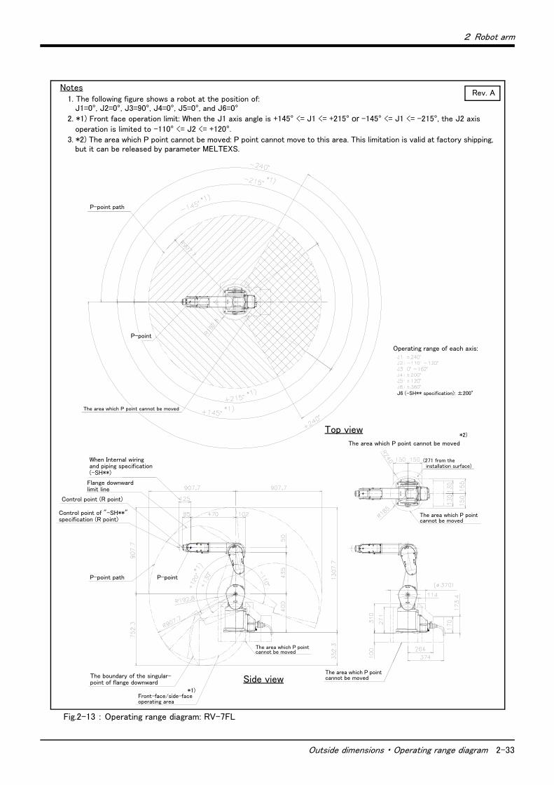
2 Robot arm
Outside dimensions ・ Operating range diagram 2-33
Fig.2-13 : Operating range diagram: RV-7FL
Side view
Top view
When Internal wiring and piping specification (-SH**)
Flange downward limit line
Control point (R point)
Control point of "-SH**" specification (R point)
Operating range of each axis:
The boundary of the singular-point of flange downward
P-point path
P-point
J6 (-SH** specification): ±200°
P-point path
Rev. A
P-point
Notes1. The following figure shows a robot at the position of:
J1=0°, J2=0°, J3=90°, J4=0°, J5=0°, and J6=0°2. *1) Front face operation limit: When the J1 axis angle is +145° <= J1 <= +215° or -145° <= J1 <= -215°, the J2 axis
operation is limited to -110° <= J2 <= +120°.3. *2) The area which P point cannot be moved: P point cannot move to this area. This limitation is valid at factory shipping,
but it can be released by parameter MELTEXS.
Front-face/side-faceoperating area
*1)
(271 from the installation surface)
The area which P point cannot be moved
The area which P point cannot be moved
The area which P point cannot be moved
*2)
The area which P point cannot be moved
The area which P point cannot be moved

2-34 Outside dimensions ・ Operating range diagram
2 Robot arm
(5) RV-7FLL
Fig.2-14 : Outside dimensions: RV-7FLL
Notes1. *1) Ensure the cable connection space to connect machine cables.2. *2) The screw should go in to a depth of 7.5mm to 8mm.3. *3) Screw hole (M4 depth 8) for securing the user cables/piping.4. *4) The size of the internal wiring and piping specification model (-SHxx).5. *5) The depth is 6mm for the normal specification, 3.5mm for the clean/oil mist specification and 6.5mm for -SH**
specification.
View A: Detail of mechanical interface View B bottom view drawing: Detail of installation dimension
Standard specification
Clean/oil mist specification
-SH** specification
Clean/oil mist specification
-SH** specification
depth 8
(Inst
alla
tion s
urf
ace)
(Installation surface)
Clean/oil mist specification
-SH** specification
Min.
Rev. A
Note) Don't install the robot arm in the position where direct rays or the heat of lighting hits. The skin temperature of the robot arm may rise, and the error may occur.
reamer
(The holes are on opposite sides.)
4-M5 screw depth 8*2)
φ20H7 depth 6
4-φ14 installation hole
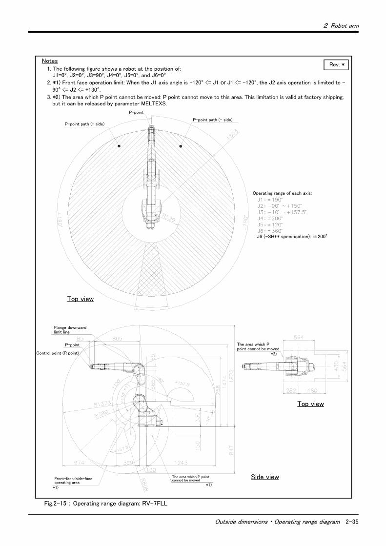
2 Robot arm
Outside dimensions ・ Operating range diagram 2-35
Fig.2-15 : Operating range diagram: RV-7FLL
Notes1. The following figure shows a robot at the position of:
J1=0°, J2=0°, J3=90°, J4=0°, J5=0°, and J6=0°2. *1) Front face operation limit: When the J1 axis angle is +120° <= J1 or J1 <= -120°, the J2 axis operation is limited to -
90° <= J2 <= +130°.3. *2) The area which P point cannot be moved: P point cannot move to this area. This limitation is valid at factory shipping,
but it can be released by parameter MELTEXS.
Top view
Flange downward limit line
Control point (R point)
P-point path (+ side)
Rev. *
P-point path (- side)
The area which P point cannot be movedFront-face/side-face
operating area*1)
P-point
Top view
Side view
Operating range of each axis:
J6 (-SH** specification): ±200°
The area which P point cannot be moved
*2)
*1)
P-point
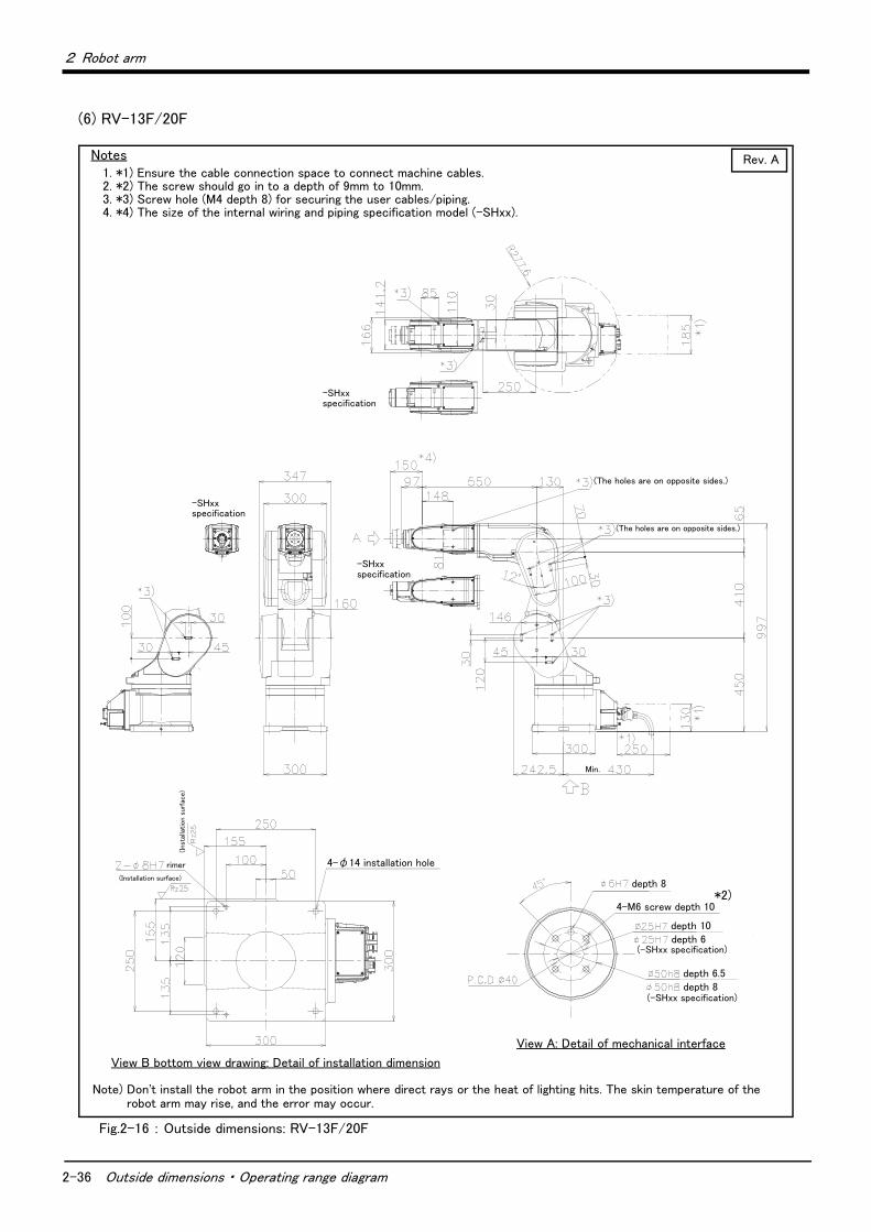
2-36 Outside dimensions ・ Operating range diagram
2 Robot arm
(6) RV-13F/20F
Fig.2-16 : Outside dimensions: RV-13F/20F
Notes1. *1) Ensure the cable connection space to connect machine cables.2. *2) The screw should go in to a depth of 9mm to 10mm.3. *3) Screw hole (M4 depth 8) for securing the user cables/piping.4. *4) The size of the internal wiring and piping specification model (-SHxx).
Note) Don't install the robot arm in the position where direct rays or the heat of lighting hits. The skin temperature of the robot arm may rise, and the error may occur.
rimer
Min.
depth 8
depth 10
depth 6.5 depth 8
(-SHxx specification)
View A: Detail of mechanical interface
Rev. A
View B bottom view drawing: Detail of installation dimension
-SHxx specification
4-φ14 installation hole
(The holes are on opposite sides.)
(The holes are on opposite sides.)
-SHxx specification
depth 6(-SHxx specification)
*2)4-M6 screw depth 10
(Installation surface)
(Ins
talla
tion
surf
ace)
-SHxx specification
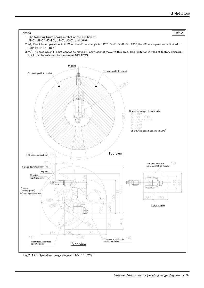
2 Robot arm
Outside dimensions ・ Operating range diagram 2-37
Fig.2-17 : Operating range diagram: RV-13F/20F
Notes1. The following figure shows a robot at the position of:
J1=0°, J2=0°, J3=90°, J4=0°, J5=0°, and J6=0°2. *1) Front face operation limit: When the J1 axis angle is +120° <= J1 or J1 <= -130°, the J2 axis operation is limited to
-90° <= J2 <= +130°.3. *2) The area which P point cannot be moved: P point cannot move to this area. This limitation is valid at factory shipping,
but it can be released by parameter MELTEXS.
Operating range of each axis:
P-point
Flange downward limit line
Rev. A
J6 (-SHxx specification): ±200°
P-point path (- side)P-point path (+ side)
Top view
Side view
Top view
The area which P point cannot be moved
(-SHxx specification)
R-point
P-point
(control point)
R-point(control point)(-SHxx specification)
The area which P point cannot be movedFront-face/side-face
operating area
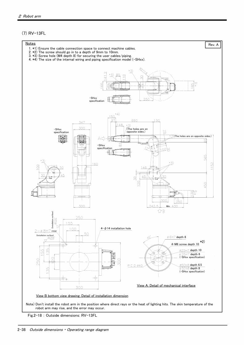
2-38 Outside dimensions ・ Operating range diagram
2 Robot arm
(7) RV-13FL
Fig.2-18 : Outside dimensions: RV-13FL
Notes1. *1) Ensure the cable connection space to connect machine cables.2. *2) The screw should go in to a depth of 9mm to 10mm.3. *3) Screw hole (M4 depth 8) for securing the user cables/piping.4. *4) The size of the internal wiring and piping specification model (-SHxx).
Note) Don't install the robot arm in the position where direct rays or the heat of lighting hits. The skin temperature of the robot arm may rise, and the error may occur.
*2)
-SHxxspecification
rimer
depth 8
depth 10
depth 6
depth 6.5 depth 8
(-SHxx specification)
View A: Detail of mechanical interface
View B bottom view drawing: Detail of installation dimension
Rev. A
(The holes are on opposite sides.)
(The holes are on opposite sides.)
-SHxxspecification
Min.
(-SHxx specification)
4-M6 screw depth 10
4-φ14 installation hole
(Installation surface)
(Ins
talla
tion s
urfa
ce)
-SHxxspecification
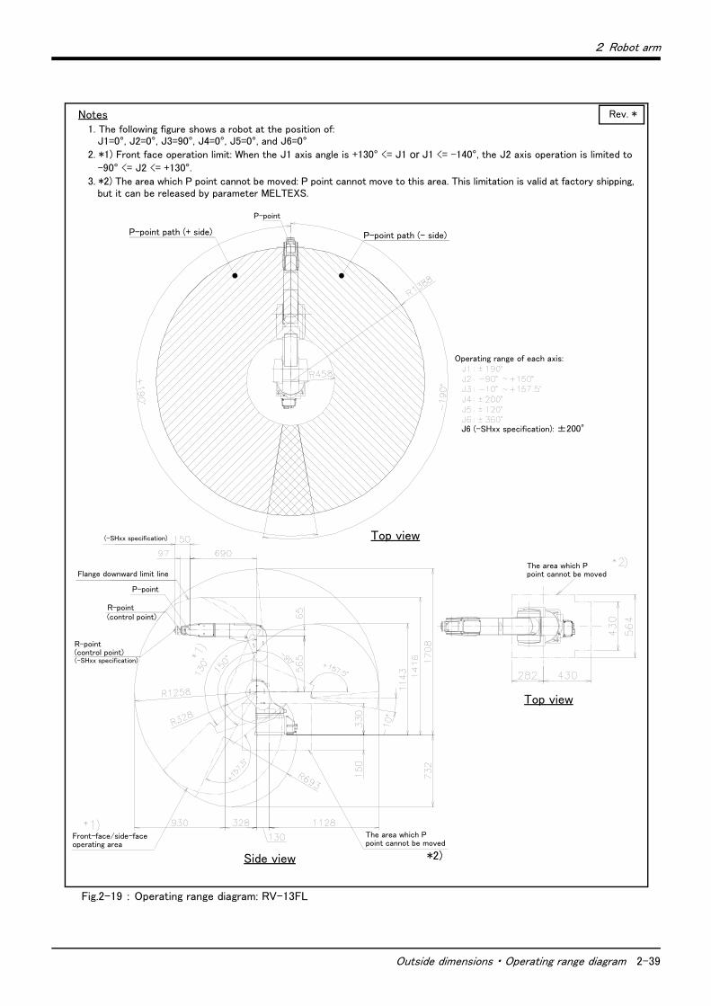
2 Robot arm
Outside dimensions ・ Operating range diagram 2-39
Fig.2-19 : Operating range diagram: RV-13FL
Notes1. The following figure shows a robot at the position of:
J1=0°, J2=0°, J3=90°, J4=0°, J5=0°, and J6=0°2. *1) Front face operation limit: When the J1 axis angle is +130° <= J1 or J1 <= -140°, the J2 axis operation is limited to
-90° <= J2 <= +130°.3. *2) The area which P point cannot be moved: P point cannot move to this area. This limitation is valid at factory shipping,
but it can be released by parameter MELTEXS.
P-point
Flange downward limit line
Rev. *
Operating range of each axis:
J6 (-SHxx specification): ±200°
P-point path (- side)P-point path (+ side)
Top view
Top view
The area which P point cannot be moved
Side view
The area which P point cannot be moved
*2)
Front-face/side-faceoperating area
R-point(control point)(-SHxx specification)
P-point
R-point(control point)
(-SHxx specification)

2-40 Tooling
2 Robot arm
2.5 Tooling
2.5.1 Wiring and piping for handShows the wiring and piping configuration for a standard-equipped hand.
(1) Standard specification (with no internal wiring and piping)
Fig.2-20 : Wiring and piping for hand
GR2GR1
RP
OP4
LAN
OP2
OP1OP3
OP1OP3OP2OP4
LAN
Primary piping pneumatic hose (AIR IN, RETURN)
Primary piping pneumatic coupling (φ6)
(AIR IN, RETURN)
Hand output signal connector (GR1, GR2)
*1) Descriptions of cable connectors
OP1: Connector for option signals
(hand input signals HC1 to HC8)
OP2: Connector for option signals
OP3: Connector for option power supply
(power supply for hand input signals)
OP4: Connector for option power supply
LAN: Connector for Ethernet options
* For details, refer to Page 47, "2.5.6 Wiring
and piping system diagram for hand".
Note 1)
Pull out the cables/ piping
When using the Hand input cable or the Hand output cable (option), the cables can be pulled out from the underneath of the forearm (shown as <A> in the figure).When using the Forearm external wiring set or the Base external wiring set (option), the cables/piping can be pulled out from the underneath of the forearm and the side of the base area. (For the pull-out position, refer to Page 73, "(7) Forearm external wiring set/ Base external wiring set".The shipping special specification model, which the cables/piping equipped into its wrist and pulled out from the mechanical interface, is also available.The details on the wiring and piping specification can be found on Page 47, "2.5.6 Wiring and piping system diagram for hand".
Mechanical interface
Fore arm
Base
Upper arm
}
φ8 coupling(Only for oil mist specification (AIR PURGE) or clean specification (VACUUM))
<A>

2 Robot arm
Tooling 2-41
(2) Internal wiring and piping specification (SH01)
Fig.2-21 : Wiring and piping for hand (SH01)
GR2GR1
RP
OP4
LAN
OP2
OP1OP3
OP1OP3OP2OP4
LAN
}
*1) The screws should go in to a depth of 7.5mm to 8mm.*2) Four air tubes have numbered marking tube. Those lengths from the cable
outlet are 300 mm.*3) Refer to Fig. 2-27 for pin assignment of the hand input cable (HC).*4) The hand input cable and two air tubes are fixed on the surface of
mechanical interface. And, all cables and hoses are fixed also in the cable outlet section.
*3)
*4)
* For details, refer to Page 47, "2.5.6 Wiring and piping system diagram for hand".
Mechanical interface (Front view)
Note1)
Primary piping pneumatic coupling (φ6)
(AIR IN, RETURN)
Base
Upper arm
Primary piping pneumatic hose
(AIR IN, RETURN)
Hand output signal connector
(GR1, GR2)
Installation position of the solenoid valve option
Fore armMechanical interface Note1)
Secondary piping pneumatic hose
(four φ4 hoses)
Hand input signal cable connector (HC)
Hand input cable
(HC)
depth 8depth 8
screw*1)
Air hoses*2)
depth 6Cab
le lengt
h o
f outs
ide t
he r
obo
t ar
m150m
m
Cable outlet

2-42 Tooling
2 Robot arm
(3) Internal wiring and piping specification (SH02)
Fig.2-22 : Wiring and piping for hand (SH02)
GR2GR1
RP
OP4
LAN
OP2
OP1OP3
OP1OP3OP2OP4
LAN
RIO
LAN
E・F1
}
*1) The screws should go in to a depth of 7.5mm to 8mm.*2) The hand input cable and two air tubes are fixed on the surface of
mechanical interface. And, all cables and hoses are fixed also in the cable outlet section.
*1)
Mechanical interface (Front view)
Note1)
Primary piping pneumatic coupling (φ6)
(AIR IN, RETURN)
Base
Upper arm
Primary piping pneumatic hose
(AIR IN, RETURN)
Hand output signal connector
(GR1, GR2)Fore arm
Mechanical interface Note1)
Hand input signal cable
connector (HC)
Force sensor unit
(E ・ F1)
* For details, refer to Page 47, "2.5.6 Wiring and piping system diagram for hand".
depth 8
depth 6Cab
le lengt
h o
f outs
ide t
he r
obo
t ar
m150m
m
Cable outlet
depth 8 screw
Vision sensor (LAN)(Ethernet)
*2)
Hand input cable(HC)
Force sensor unit (E ・ F1)
Vision sensor (LAN)
(Ethernet)

2 Robot arm
Tooling 2-43
(4) Internal wiring and piping specification (SH03)
Fig.2-23 : Wiring and piping for hand (SH03)
GR2GR1
RP
OP4
LAN
OP2
OP1OP3
OP1OP3OP2OP4
LAN
RIO
LAN
E・F1
E・F2
}
*1) The screws should go in to a depth of 7.5mm to 8mm.*2) The hand input cable and two air tubes are fixed on the surface of
mechanical interface. And, all cables and hoses are fixed also in the cable outlet section.
*1)
*2)
Reserved (E ・ F1)
Mechanical interface (Front view)
Note1)
Primary piping pneumatic coupling (φ6)
(AIR IN, RETURN)
Base
Upper arm
Primary piping pneumatic hose
(AIR IN, RETURN)
Hand output signal connector
(GR1, GR2)Fore arm
Mechanical interface Note1)
Force sensor unit
(E ・ F2)
Vision sensor (LAN)
(Ethernet)
depth 8
depth 6
Cab
le lengt
h o
f out
side
the r
obo
t ar
m150m
m
Cable outlet
depth 8 screw
Reserved Force sensor unit(E ・ F2)
Vision sensor (LAN)(Ethernet)
* For details, refer to Page 47, "2.5.6 Wiring and piping system diagram for hand".
(E ・ F1)
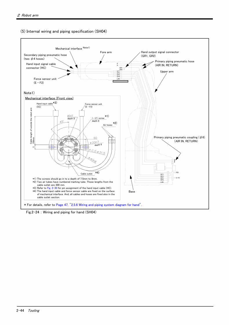
2-44 Tooling
2 Robot arm
(5) Internal wiring and piping specification (SH04)
Fig.2-24 : Wiring and piping for hand (SH04)
GR2GR1
RP
OP4
LAN
OP2
OP1OP3
OP1OP3OP2OP4
LAN
RIO
E・F2
}
*1) The screws should go in to a depth of 7.5mm to 8mm.*2) Two air tubes have numbered marking tube. Those lengths from the
cable outlet are 300 mm.*3) Refer to Fig. 2-30 for pin assignment of the hand input cable (HC).*4) The hand input cable and force sensor cable are fixed on the surface
of mechanical interface. And, all cables and hoses are fixed also in the cable outlet section.
*4)
Mechanical interface (Front view)
Note1)
Primary piping pneumatic coupling (φ6)
(AIR IN, RETURN)
Upper arm
Primary piping pneumatic hose
(AIR IN, RETURN)
Hand output signal connector
(GR1, GR2)Fore arm
Mechanical interface Note1)
Secondary piping pneumatic hose
(two φ4 hoses)
Hand input signal cable
connector (HC)
Force sensor unit
(E ・ F2)
Base
depth 8
depth 6
Cab
le lengt
h o
f outs
ide t
he r
obo
t ar
m150m
m
Cable outlet
depth 8 screw
Hand input cable Force sensor unit(E ・ F2)
Air hoses*2)
*1)
(HC)
*3)
* For details, refer to Page 47, "2.5.6 Wiring and piping system diagram for hand".

2 Robot arm
Tooling 2-45
(6) Internal wiring and piping specification (SH05)
Fig.2-25 : Wiring and piping for hand (SH05)
GR2GR1
RP
OP4
LAN
OP2
OP1OP3
OP1OP3OP2OP4
LAN
RIO
LAN
}
Vision sensor (LAN)
(Ethernet)
*1) The screws should go in to a depth of 7.5mm to 8mm.*2) Two air tubes have numbered marking tube. Those lengths from the
cable outlet are 300 mm.*3) Refer to Fig. 2-31 for pin assignment of the hand input cable (HC).*4) The hand input cable and force sensor cable are fixed on the surface
of mechanical interface. And, all cables and hoses are fixed also in the cable outlet section.
*4)
Mechanical interface (Front view)
Note1)
Primary piping pneumatic coupling (φ6)
(AIR IN, RETURN)
Upper arm
Primary piping pneumatic hose
(AIR IN, RETURN)
Hand output signal connector
(GR1, GR2)
Fore armMechanical interface Note1)
Secondary piping pneumatic hose
(two φ4 hoses)
Hand input signal cable
connector (HC)
Base
depth 6
Cab
le lengt
h o
f outs
ide t
he r
obo
t ar
m150m
m
Cable outlet
depth 8 screw
Hand input cable Vision sensor(LAN)
Air hoses
depth 8*1)
*2)
(HC)
*3)
* For details, refer to Page 47, "2.5.6 Wiring and piping system diagram for hand".
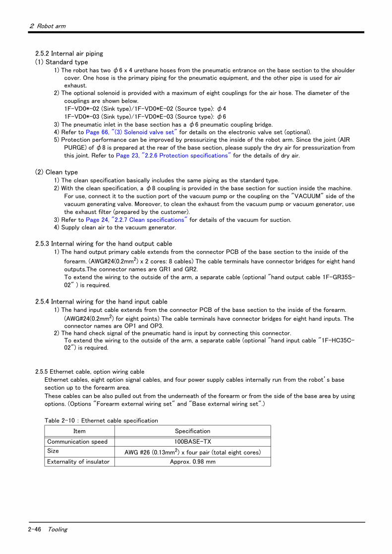
2-46 Tooling
2 Robot arm
2.5.2 Internal air piping(1) Standard type
1) The robot has two φ6 x 4 urethane hoses from the pneumatic entrance on the base section to the shoulder cover. One hose is the primary piping for the pneumatic equipment, and the other pipe is used for air exhaust.
2) The optional solenoid is provided with a maximum of eight couplings for the air hose. The diameter of the couplings are shown below.1F-VD0*-02 (Sink type)/1F-VD0*E-02 (Source type): φ41F-VD0*-03 (Sink type)/1F-VD0*E-03 (Source type): φ6
3) The pneumatic inlet in the base section has a φ6 pneumatic coupling bridge.4) Refer to Page 66, "(3) Solenoid valve set" for details on the electronic valve set (optional).5) Protection performance can be improved by pressurizing the inside of the robot arm. Since the joint (AIR
PURGE) of φ8 is prepared at the rear of the base section, please supply the dry air for pressurization from this joint. Refer to Page 23, "2.2.6 Protection specifications" for the details of dry air.
(2) Clean type1) The clean specification basically includes the same piping as the standard type.2) With the clean specification, a φ8 coupling is provided in the base section for suction inside the machine.
For use, connect it to the suction port of the vacuum pump or the coupling on the "VACUUM" side of the vacuum generating valve. Moreover, to clean the exhaust from the vacuum pump or vacuum generator, use the exhaust filter (prepared by the customer).
3) Refer to Page 24, "2.2.7 Clean specifications" for details of the vacuum for suction.4) Supply clean air to the vacuum generator.
2.5.3 Internal wiring for the hand output cable1) The hand output primary cable extends from the connector PCB of the base section to the inside of the
forearm. (AWG#24(0.2mm2) x 2 cores: 8 cables) The cable terminals have connector bridges for eight hand outputs.The connector names are GR1 and GR2. To extend the wiring to the outside of the arm, a separate cable (optional "hand output cable 1F-GR35S-02" ) is required.
2.5.4 Internal wiring for the hand input cable1) The hand input cable extends from the connector PCB of the base section to the inside of the forearm.
(AWG#24(0.2mm2) for eight points) The cable terminals have connector bridges for eight hand inputs. The connector names are OP1 and OP3.
2) The hand check signal of the pneumatic hand is input by connecting this connector.To extend the wiring to the outside of the arm, a separate cable (optional "hand input cable "1F-HC35C-02") is required.
2.5.5 Ethernet cable, option wiring cableEthernet cables, eight option signal cables, and four power supply cables internally run from the robot’s base section up to the forearm area.
These cables can be also pulled out from the underneath of the forearm or from the side of the base area by using options. (Options "Forearm external wiring set" and "Base external wiring set".)
Table 2-10 : Ethernet cable specification
Item Specification
Communication speed 100BASE-TX
Size AWG #26 (0.13mm2) x four pair (total eight cores)
Externality of insulator Approx. 0.98 mm
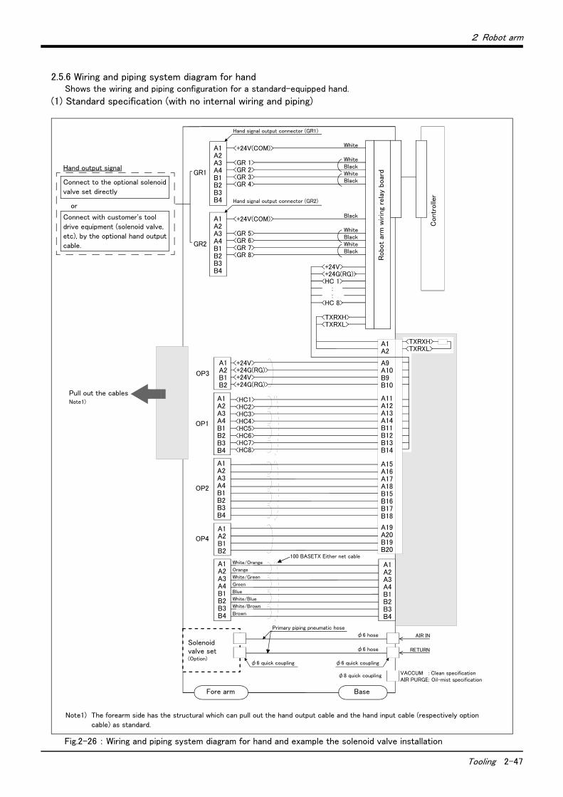
2 Robot arm
Tooling 2-47
2.5.6 Wiring and piping system diagram for handShows the wiring and piping configuration for a standard-equipped hand.
(1) Standard specification (with no internal wiring and piping)
Fig.2-26 : Wiring and piping system diagram for hand and example the solenoid valve installation
白 A1A2A3A4B1B2B3B4
コントローラ
ロボット本体配線中継ボード
<+24V(COM)>
<GR 1><GR 2><GR 3><GR 4>
A1A2A3A4B1B2B3B4
<+24V(COM)>
<GR 5><GR 6><GR 7><GR 8>
ハンド信号出力用コネクタ(GR2コネクタ)
ハンド信号出力用コネクタ(GR1コネクタ)
白橙橙白緑緑青白青白茶茶
φ6クイック継手
1次配管エアホース
φ6ホース
φ6ホース
φ6クイック継手
AIR IN
RETURN
フォアアーム内 ベース部
φ8クイック継手
白
黒
白
黒
黒
白
黒
白
黒
<+24V><+24G(RG)><HC 1> : :<HC 8>
<TXRXH><TXRXL>
<HC1><HC2><HC3><HC4><HC5><HC6><HC7><HC8>
A1A2A3A4B1B2B3B4
A1A2B1B2
<+24V><+24G(RG)><+24V><+24G(RG)>
A1A2B1B2
A1A2A3A4B1B2B3B4
OP3
OP1
OP2
OP4
100BASETXイーサネットケーブル
GR1
GR2
<TXRXH><TXRXL>
A1A2
A15A16A17A18B15B16B17B18
A19A20B19B20
A9A10B9B10
A11A12A13A14B11B12B13B14
A1A2A3A4B1B2B3B4
A1A2A3A4B1B2B3B4
電磁弁セット(オプション)
オイルミスト仕様(加圧)クリーン仕様(吸引)のみ
Hand output signal
Connect to the optional solenoid
valve set directly
or
Connect with customer's tool
drive equipment (solenoid valve,
etc), by the optional hand output
cable.
Note1) The forearm side has the structural which can pull out the hand output cable and the hand input cable (respectively option
cable) as standard.
Pull out the cables Note1)
Hand signal output connector (GR1)
White
WhiteBlackWhiteBlack
Hand signal output connector (GR2)
Black
WhiteBlackWhiteBlack
Robo
t ar
m w
irin
g re
lay
boar
d
Contr
olle
r
White/Orange
Orange
White/Green
Green
Blue
White/Blue
White/Brown
Brown
100 BASETX Either net cable
Primary piping pneumatic hose
Solenoid valve set (Option)
φ6 quick coupling φ6 quick coupling
φ6 hose
φ6 hose
φ8 quick coupling VACCUM : Clean specificationAIR PURGE: Oil-mist specification
Fore arm Base

2-48 Tooling
2 Robot arm
(2) Internal wiring and piping specification (SH01)
Fig.2-27 : Wiring and piping system diagram for hand and example the solenoid valve installation: SH01
白 A1A2A3A4B1B2B3B4
コントローラ
ロボット本体配線中継ボード
<+24V(COM)>
<GR 1><GR 2><GR 3><GR 4>
A1A2A3A4B1B2B3B4
<+24V(COM)>
<GR 5><GR 6><GR 7><GR 8>
ハンド信号出力用コネクタ(GR2コネクタ)
ハンド信号出力用コネクタ(GR1コネクタ)
白橙橙白緑緑青白青白茶茶
φ6クイック継手
1次配管エアホース
φ6ホース
φ6ホース
φ6クイック継手
AIR IN
RETURN
フォアアーム内 ベース部
φ8クイック継手
白
黒
白
黒
黒
白
黒
白
黒
<+24V><+24G(RG)><HC 1> : :<HC 8>
<TXRXH><TXRXL>
<HC1><HC2><HC3><HC4><HC5><HC6><HC7><HC8>
A1A2A3A4B1B2B3B4
A1A2B1B2
<+24V><+24G(RG)><+24V><+24G(RG)>
A1A2B1B2
A1A2A3A4B1B2B3B4
OP3
OP1
OP2
OP4
100BASETXイーサネットケーブル
GR1
GR2
<TXRXH><TXRXL>
A1A2
A15A16A17A18B15B16B17B18
A19A20B19B20
A9A10B9B10
A11A12A13A14B11B12B13B14
A1A2A3A4B1B2B3B4
A1A2A3A4B1B2B3B4
電磁弁セット(オプション)
オイルミスト仕様(加圧)クリーン仕様(吸引)のみ
Hand output signal
Connect to the optional solenoid
valve set directly
or
Connect with customer's tool
drive equipment (solenoid valve,
etc), by the optional hand output
cable.
Hand signal output connector (GR1)
White
WhiteBlackWhiteBlack
Hand signal output connector (GR2)
Black
WhiteBlackWhiteBlack
Robo
t ar
m w
irin
g re
lay
boar
d
Contr
olle
r
White/Orange
Orange
White/Green
Green
Blue
White/Blue
White/Brown
Brown
100 BASETX Either net cable
Primary piping pneumatic hose
Solenoid valve set (Option)
φ6 quick coupling φ6 quick coupling
φ6 hose
φ6 hose
φ8 quick couplingVACCUM : Clean specificationAIR PURGE: Oil-mist specification
Fore arm Base
Hand input signals
Mechanical interface
Note1) The pin assignment of hand input signal connector.
<HC1><HC2><HC3><HC4><24V><HC5><HC6><HC7><HC8><24G(RG)>
A1A2A3A4A6B1B2B3B4B6
Connector
Manufacturer: Tyco Electronics AMP
Robot arm side: 1-1827864-6
Customer-prepared side: 1-1903130-6
1 2 3 4Air tube (φ4x4)
HCNote1)

2 Robot arm
Tooling 2-49
(3) Internal wiring and piping specification (SH02)
Fig.2-28 : Wiring and piping system diagram for hand and example the solenoid valve installation: SH02
白 A1A2A3A4B1B2B3B4
コントローラ
ロボット本体配線中継ボード
<+24V(COM)>
<GR 1><GR 2><GR 3><GR 4>
A1A2A3A4B1B2B3B4
<+24V(COM)>
<GR 5><GR 6><GR 7><GR 8>
ハンド信号出力用コネクタ(GR2コネクタ)
ハンド信号出力用コネクタ(GR1コネクタ)
白橙橙白緑緑青白青白茶茶
φ6クイック継手
1次配管エアホース
φ6ホース
φ6ホース
φ6クイック継手
AIR IN
RETURN
フォアアーム内 ベース部
φ8クイック継手
白
黒
白
黒
黒
白
黒
白
黒
<+24V><+24G(RG)><HC 1> : :<HC 8>
<TXRXH><TXRXL>
<HC1><HC2><HC3><HC4><HC5><HC6><HC7><HC8>
A1A2A3A4B1B2B3B4
A1A2B1B2
<+24V><+24G(RG)><+24V><+24G(RG)>
A1A2B1B2
A1A2A3A4B1B2B3B4
OP3
OP1
OP2
OP4
100BASETXイーサネットケーブル
GR1
GR2
A1A2A3A4
A15A16A17A18B15B16B17B18
A19A20B19B20
A9A10B9B10
A11A12A13A14B11B12B13B14
A1A2A3A4B1B2B3B4
電磁弁セット(オプション)
オイルミスト仕様(加圧)クリーン仕様(吸引)のみ
<TXRXH><TXRXL><+24G(RG)><+24V>
A1A2A3A4B1B2B3B4
Hand output signal
Connect to the optional solenoid
valve set directly
or
Connect with customer's tool
drive equipment (solenoid valve,
etc), by the optional hand output
cable.
Note1) When using a force sensor, use the supplied adaptor cable to connect to the force sensor option.
Hand signal output connector (GR1)
White
WhiteBlackWhiteBlack
Hand signal output connector (GR2)
Black
WhiteBlackWhiteBlack
Robo
t ar
m w
irin
g re
lay
boar
d
Contr
olle
r
White/Orange
Orange
White/Green
Green
Blue
White/Blue
White/Brown
Brown
100 BASETX Either net cable
Primary piping pneumatic hose
Solenoid valve set (Option)
φ6 quick coupling φ6 quick coupling
φ6 hose
φ6 hose
φ8 quick coupling VACCUM : Clean specificationAIR PURGE: Oil-mist specification
Fore arm BaseHand input signals Note2)
Mechanical interface
Vision-sensor camera. (Ethernet)
Force sensor Note1)
Reserved
Option (attached):1F-HA01S-01
Connects with force sensor
interface Note1)
Connects with the vision-sen-sor controller
Note2) The pin assignment of hand input signal connector.
<HC1><HC2><HC3><HC4><24V><HC5><HC6><HC7><HC8><24G(RG)>
A1A2A3A4A6B1B2B3B4B6
Connector
Manufacturer: Tyco Electronics AMP
Robot arm side: 1-1827864-6
Customer-prepared side: 1-1903130-6
HC
E ・ F1
LAN
RIO
E ・ F1
LAN

2-50 Tooling
2 Robot arm
(4) Internal wiring and piping specification (SH03)
Fig.2-29 : Wiring and piping system diagram for hand and example the solenoid valve installation:SH03
白 A1A2A3A4B1B2B3B4
コントローラ
ロボット本体配線中継ボード
<+24V(COM)>
<GR 1><GR 2><GR 3><GR 4>
A1A2A3A4B1B2B3B4
<+24V(COM)>
<GR 5><GR 6><GR 7><GR 8>
ハンド信号出力用コネクタ(GR2コネクタ)
ハンド信号出力用コネクタ(GR1コネクタ)
白橙橙白緑緑青白青白茶茶
φ6クイック継手
1次配管エアホース
φ6ホース
φ6ホース
φ6クイック継手
AIR IN
RETURN
フォアアーム内 ベース部
φ8クイック継手
白
黒
白
黒
黒
白
黒
白
黒
<+24V><+24G(RG)><HC 1> : :<HC 8>
<TXRXH><TXRXL>
<HC1><HC2><HC3><HC4><HC5><HC6><HC7><HC8>
A1A2A3A4B1B2B3B4
A1A2B1B2
<+24V><+24G(RG)><+24V><+24G(RG)>
A1A2B1B2
A1A2A3A4B1B2B3B4
OP3
OP1
OP2
OP4
100BASETXイーサネットケーブル
GR1
GR2
A1A2A3A4
A15A16A17A18B15B16B17B18
A19A20B19B20
A9A10B9B10
A11A12A13A14B11B12B13B14
A1A2A3A4B1B2B3B4
電磁弁セット(オプション)
オイルミスト仕様(加圧)クリーン仕様(吸引)のみ
<TXRXH><TXRXL><+24G(RG)><+24V>
A1A2A3A4B1B2B3B4
Hand output signal
Connect to the optional solenoid
valve set directly
or
Connect with customer's tool
drive equipment (solenoid valve,
etc), by the optional hand output
cable.
Note1) When using a force sensor, use the supplied adaptor cable to connect to the force sensor option.
Hand signal output connector (GR1)
White
WhiteBlackWhiteBlack
Hand signal output connector (GR2)
Black
WhiteBlackWhiteBlack
Robo
t ar
m w
irin
g re
lay
boar
d
Contr
olle
r
White/Orange
Orange
White/Green
Green
Blue
White/Blue
White/Brown
Brown
100 BASETX Either net cable
Primary piping pneumatic hose
Solenoid valve set (Option)
φ6 quick coupling φ6 quick coupling
φ6 hose
φ6 hose
φ8 quick coupling VACCUM : Clean specificationAIR PURGE: Oil-mist specification
Fore arm BaseReserved
Mechanical interface
Vision-sensor camera. (Ethernet)
Force sensor Note1)
Reserved
Option (attached):1F-HA01S-01
Connects with force sensor
interface Note1)
Connects with the vision-sen-sor controller
E ・ F2
LAN
RIO
Reserved
E ・ F2
LAN
E ・ F1
E ・ F1

2 Robot arm
Tooling 2-51
(5) Internal wiring and piping specification (SH04)
Fig.2-30 : Wiring and piping system diagram for hand and example the solenoid valve installation:SH04
白 A1A2A3A4B1B2B3B4
コントローラ
ロボット本体配線中継ボード
<+24V(COM)>
<GR 1><GR 2><GR 3><GR 4>
A1A2A3A4B1B2B3B4
<+24V(COM)>
<GR 5><GR 6><GR 7><GR 8>
ハンド信号出力用コネクタ(GR2コネクタ)
ハンド信号出力用コネクタ(GR1コネクタ)
白橙橙白緑緑青白青白茶茶
φ6クイック継手
1次配管エアホース
φ6ホース
φ6ホース
φ6クイック継手
AIR IN
RETURN
フォアアーム内 ベース部
φ8クイック継手
白
黒
白
黒
黒
白
黒
白
黒
<+24V><+24G(RG)><HC 1> : :<HC 8>
<TXRXH><TXRXL>
<HC1><HC2><HC3><HC4><HC5><HC6><HC7><HC8>
A1A2A3A4B1B2B3B4
A1A2B1B2
<+24V><+24G(RG)><+24V><+24G(RG)>
A1A2B1B2
A1A2A3A4B1B2B3B4
OP3
OP1
OP2
OP4
100BASETXイーサネットケーブル
GR1
GR2
A1A2A3A4
A15A16A17A18B15B16B17B18
A19A20B19B20
A9A10B9B10
A11A12A13A14B11B12B13B14
A1A2A3A4B1B2B3B4
電磁弁セット(オプション)
オイルミスト仕様(加圧)クリーン仕様(吸引)のみ
<TXRXH><TXRXL><+24G(RG)><+24V>
A1A2A3A4B1B2B3B4
Hand output signal
Connect to the optional solenoid
valve set directly
or
Connect with customer's tool
drive equipment (solenoid valve,
etc), by the optional hand output
cable.
Note1) When using a force sensor, use the supplied adaptor cable to connect to the force sensor option.
Hand signal output connector (GR1)
White
WhiteBlackWhiteBlack
Hand signal output connector (GR2)
Black
WhiteBlackWhiteBlack
Robo
t ar
m w
irin
g re
lay
boar
d
Contr
olle
r
White/Orange
Orange
White/Green
Green
Blue
White/Blue
White/Brown
Brown
100 BASETX Either net cable
Primary piping pneumatic hose
Solenoid valve set (Option)
φ6 quick coupling φ6 quick coupling
φ6 hose
φ6 hose
φ8 quick couplingVACCUM : Clean specificationAIR PURGE: Oil-mist specification
Fore arm Base
Mechanical interface
Air tube (φ4x2)
Force sensor Note1)
Reserved
Option (attached):1F-HA01S-01
Connects with force sensor
interface Note1)
E ・ F2
RIO
E ・ F2
Note2) The pin assignment of hand input signal connector.
<HC1><HC2><HC3><HC4><24V><HC5><HC6><HC7><HC8><24G(RG)>
A1A2A3A4A6B1B2B3B4B6
Connector
Manufacturer: Tyco Electronics AMP
Robot arm side: 1-1827864-6
Customer-prepared side: 1-1903130-6
1 2
Hand input signals Note2)
HC

2-52 Tooling
2 Robot arm
(6) Internal wiring and piping specification (SH05)
Fig.2-31 : Wiring and piping system diagram for hand and example the solenoid valve installation:SH05
白 A1A2A3A4B1B2B3B4
コントローラ
ロボット本体配線中継ボード
<+24V(COM)>
<GR 1><GR 2><GR 3><GR 4>
A1A2A3A4B1B2B3B4
<+24V(COM)>
<GR 5><GR 6><GR 7><GR 8>
ハンド信号出力用コネクタ(GR2コネクタ)
ハンド信号出力用コネクタ(GR1コネクタ)
白橙橙白緑緑青白青白茶茶
φ6クイック継手
1次配管エアホース
φ6ホース
φ6ホース
φ6クイック継手
AIR IN
RETURN
フォアアーム内 ベース部
φ8クイック継手
白
黒
白
黒
黒
白
黒
白
黒
<+24V><+24G(RG)><HC 1> : :<HC 8>
<TXRXH><TXRXL>
<HC1><HC2><HC3><HC4><HC5><HC6><HC7><HC8>
A1A2A3A4B1B2B3B4
A1A2B1B2
<+24V><+24G(RG)><+24V><+24G(RG)>
A1A2B1B2
A1A2A3A4B1B2B3B4
OP3
OP1
OP2
OP4
100BASETXイーサネットケーブル
GR1
GR2
A1A2A3A4
A15A16A17A18B15B16B17B18
A19A20B19B20
A9A10B9B10
A11A12A13A14B11B12B13B14
A1A2A3A4B1B2B3B4
電磁弁セット(オプション)
オイルミスト仕様(加圧)クリーン仕様(吸引)のみ
<TXRXH><TXRXL><+24G(RG)><+24V>
A1A2A3A4B1B2B3B4
Hand output signal
Connect to the optional solenoid
valve set directly
or
Connect with customer's tool
drive equipment (solenoid valve,
etc), by the optional hand output
cable.
Hand signal output connector (GR1)
White
WhiteBlackWhiteBlack
Hand signal output connector (GR2)
Black
WhiteBlackWhiteBlack
Robo
t ar
m w
irin
g re
lay
boar
d
Contr
olle
r
White/Orange
Orange
White/Green
Green
Blue
White/Blue
White/Brown
Brown
100 BASETX Either net cable
Primary piping pneumatic hose
Solenoid valve set (Option)
φ6 quick coupling φ6 quick coupling
φ6 hose
φ6 hose
φ8 quick coupling VACCUM : Clean specificationAIR PURGE: Oil-mist specification
Fore arm Base
Mechanical interface
Air tube (φ4x2)
Vision-sensor camera. (Ethernet)
Reserved
Option (attached):1F-HA01S-01
Connects with vision sensor
controller
LAN
RIO
LAN
Note1) The pin assignment of hand input signal connector.
<HC1><HC2><HC3><HC4><24V><HC5><HC6><HC7><HC8><24G(RG)>
A1A2A3A4A6B1B2B3B4B6
Connector
Manufacturer: Tyco Electronics AMP
Robot arm side: 1-1827864-6
Customer-prepared side: 1-1903130-6
1 2
Hand input signals Note1)
HC
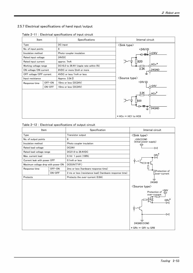
2 Robot arm
Tooling 2-53
2.5.7 Electrical specifications of hand input/output
Table 2-11 : Electrical specifications of input circuit
Table 2-12 : Electrical specifications of output circuit
Item Specifications Internal circuit
Type DC input <Sink type>
<Source type>
* HCn = HC1 to HC8
No. of input points 8
Insulation method Photo-coupler insulation
Rated input voltage 24VDC
Rated input current approx. 7mA
Working voltage range DC10.2 to 26.4V (ripple rate within 5%)
ON voltage/ON current 8VDC or more/2mA or more
OFF voltage/OFF current 4VDC or less/1mA or less
Input resistance Approx. 3.3kΩ
Response time
OFF-ON 10ms or less (DC24V)
ON-OFF 10ms or less (DC24V)
Item Specification Internal circuit
Type Transistor output <Sink type>
<Source type>
* GRn = GR1 to GR8
No. of output points 8
Insulation method Photo coupler insulation
Rated load voltage DC24V
Rated load voltage range DC21.6 to 26.4VDC
Max. current load 0.1A/ 1 point (100%)
Current leak with power OFF 0.1mA or less
Maximum voltage drop with power ON DC0.9V(TYP.)
Response time OFF-ON 2ms or less (hardware response time)
ON-OFF 2 ms or less (resistance load) (hardware response time)
Protects Protects the over-current (0.9A)
3.3K
+24V
24GND
820HCn*
+24V
3.3K
820
24GND
+24V
HCn*
+24V
+24V(COM) (内部電源)
*GRn
過電流保護機能
24GND
Protection of over-current
(Initial power supply)
* GRn
+24V
24GND(COM)
過電流保護機能
Protection of over-current
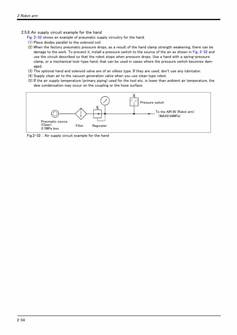
2-54
2 Robot arm
2.5.8 Air supply circuit example for the handFig. 2-32 shows an example of pneumatic supply circuitry for the hand.
(1) Place diodes parallel to the solenoid coil.(2) When the factory pneumatic pressure drops, as a result of the hand clamp strength weakening, there can be
damage to the work. To prevent it, install a pressure switch to the source of the air as shown in Fig. 2-32 and use the circuit described so that the robot stops when pressure drops. Use a hand with a spring-pressure clamp, or a mechanical lock-type hand, that can be used in cases where the pressure switch becomes dam-aged.
(3) The optional hand and solenoid valve are of an oilless type. If they are used, don't use any lubricator.(4) Supply clean air to the vacuum generation valve when you use clean type robot.(5) If the air supply temperature (primary piping) used for the tool etc. is lower than ambient air temperature, the
dew condensation may occur on the coupling or the hose surface.
Fig.2-32 : Air supply circuit example for the hand
Pressure switch
To the AIR IN (Robot arm)(MAX0.54MPa)
Pneumatic source
0.7MPa less Filter Regurater(Clean)
2 Robot arm
Shipping special specifications, options, and maintenance parts 2-55
2.6 Shipping special specifications, options, and maintenance parts
2.6.1 Shipping special specifications
■ What are sipping special specifications?Shipping special specifications are changed before shipping from the factory. Consequently, it is necessary to confirm the delivery date by the customer.
To make changes to the specifications after shipment, service work must be performed at the work site or the robot must be returned for service.
■ How to order(1) Confirm beforehand when the factory special specifications can be shipped, because they may not be
immediately available.(2) Specify, before shipping from our company.(3) Specified method …… Specify the part name, model, and robot model type.

2-56 Shipping special specifications, options, and maintenance parts
2 Robot arm
(1) Machine cable
■ Order type: ● Fixed type .........1S-02UCBL-1 (2m)
■ Outline
This cable is exchanged for the machine cable that was supplied as standard to shorten the distance between the controller and the robot arm.
■ ConfigurationTable 2-13 : Configuration equipment and types
[Caution] Orders made after purchasing a robot are treated as purchases of optional equipment. In this case, themachine cable that was supplied as standard is not reclaimed.
Part name Type Qty. Mass(kg)Note1)
Note1) Mass indicates one set.
RemarksNote2)
Note2) A standard machine cable (for fixed type) is not attached.
Fixed Set of signal and power cables 1S-02UCBL-01 1 set 3.4 2m
Motor signal cable BKO-FA0741H02 (1 cable) -
Motor power cable BKO-FA0739H02 (1 cable) -

2 Robot arm
Options 2-57
2.7 Options
■ What are options?There are a variety of options for the robot designed to make the setting up process easier for customer needs.
customer installation is required for the options. Options come in two types: "set options" and "single options".
1. Set options .......................................A combination of single options and parts that together, from a set for servingsome purpose.
2. Single options ..................................That are configured from the fewest number of required units of a part.Please choose customer's purpose additionally.

2-58 Options
2 Robot arm
(1) Machine cable extension
■ Order type: ● Fixed type 1S- □□ CBL-01● Flexed type 1S- □□ LCBL-01 Note) The numbers in the boxes □□ refer the length.
■ Outline
The distance between the robot controller and the robot arm is extensible by this option. This cable is extended to the machine cable attached as standard.
A fixed type and flexible type are available.
The extended method is discriminated as follows.
Fixed type/Flexed type: ・ Adds to the machine cable attached in the standards.
The fix and flexible types are both configured of the motor signal cable and motor power cable.
■ ConfigurationTable 2-14 : Configuration equipment and types
■ SpecificationsThe specifications for the fixed type cables are the same as those for standard cables.
Shows usage conditions for flexed type cables in Table 2-15.
Table 2-15 : Conditions for the flexed type cables
[Caution] The guidance of life count may greatly differ according to the usage state (items related to Table 2-15and to the amount of silicon grease applied in the cableveyor.
Part name TypeNote1)
Note1) The numbers in the boxes □□ refer the length.
Qty. Mass(kg)Note2)
Note2) Mass indicates one set.
RemarksFixed Flexed
Fixed Set of signal and power cables 1S- □□ CBL-01 1 set - 6.7(5m)
12(10m)
17(15m)
5m, 10m, or 15m each
Motor signal cable 1S- □□ CBL(S)-01 (1 cable) -
Motor power cable 1S- □□ CBL(P)-01 (1 cable) -
Flexed Set of signal and power cables 1S- □□ LCBL-01 - 1 set 7(5m)
13(10m)
17(15m)
5m, 10m, or 15m each
Motor signal cable 1S- □□ LCBL(S)-01 - (1 cable)
Motor power cable 1S- □□ LCBL(P)-01 - (1 cable)
Nylon clamp NK-14N - 2 pcs. - for motor signal cable
Nylon clamp NK-18N - 2 pcs. - for motor power cable
Silicon rubber - 4 pcs. -
Item Specifications
Minimum flexed radius 100R or more
Cableveyor, etc., occupation rate 50% or less
Maximum movement speed 2,000mm/s or less
Guidance of life count 7.5 million times
Environmental proof Oil-proof specification sheath
(for silicon grease, cable sliding lubricant type) IP54
Cable configuration Motor signal cable φ6 x 5, φ8.5 x 1 and φ1.7 x 1
Motor power cable φ8.9 x 2 and φ6.5 x 8

2 Robot arm
Options 2-59
■ Cable configurationThe configuration of the flexible cable is shown in Table 2-16. Refer to this table when selecting the cableveyor.
Table 2-16 : Cable configuration (Flexed type)
Note) The square in the cable name indicates the cable length.
ItemMotor signal cable
1S- □□ LCBL(S)-01
Motor power cable
1D- □□ LCBL(P)-01
No. of cores AWG#24(0.2mm2)-4P AWG#24(0.2mm2)-7P AWG#18(0.75mm2) AWG#17(1.25mm2)-4C AWG#19(0.75mm2)-4C
Finish dimensions Approx. φ6mm Approx. φ8.5mm Approx. φ1.7mm Approx. φ8.9mm Approx. φ6.5mm
No.of cables used 5 cables 1 cable 1 cable 2 cable 8 cable
No. in total 7 cables 10 cables
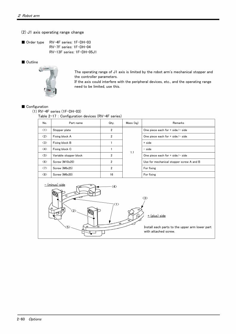
2-60 Options
2 Robot arm
(2) J1 axis operating range change
■ Order type RV-4F series: 1F-DH-03RV-7F series: 1F-DH-04
RV-13F series: 1F-DH-05J1
■ Outline
The operating range of J1 axis is limited by the robot arm's mechanical stopper and the controller parameters.
If the axis could interfere with the peripheral devices, etc., and the operating range need to be limited, use this.
■ Configuration(1) RV-4F series (1F-DH-03)
Table 2-17 : Configuration devices (RV-4F series)
No. Part name Qty. Mass (kg) Remarks
<1> Stopper plate 2
1.1
One piece each for + side/- side
<2> Fixing block A 2 One piece each for + side/- side
<3> Fixing block B 1 + side
<4> Fixing block C 1 - side
<5> Variable stopper block 2 One piece each for + side/- side
<6> Screw (M10x20) 2 Use for mechanical stopper screw A and B
<7> Screw (M6x25) 2 For fixing
<8> Screw (M6x20) 16 For fixing
<1>
<5>
<4>
<3>
<2>
Install each parts to the upper arm lower part with attached screw.
+ (plus) side
- (minus) side

2 Robot arm
Options 2-61
Table 2-18 : Changeable angle (RV-4F series)
1) The changeable angle of RV-4F series is shown in Table 2-18. The changeable angle shown in Table 2-18 indicates the operation range by the software. The limit by the mechanical stopper is positioned three degrees outward from that angle, so take care when designing the layout.
2) The changeable angle can be set independently on the + (plus) side/ - (minus) side, within the condition shown in Table 2-18.
3) The operating range is changed with robot arm settings and parameter settings. Refer to the separate "Instruction Manual/ROBOT ARM SETUP & MAINTENANCE" or "Instruction Manual/Detailed Explanation of Functions and Operations" for details.
Item Standard Changeable angle (combination of + side/- side) (Unit: Degree)
+ (plus) side +240 +30 +73 +103 +146
Variable stopper block angle - +33 +76 +106 +149
Variable stopper block position Note1)
Note1) Symbol: “(a)” - “(d)” are related with the symbol of Page 63 "Fig. 2-33: Installation image of J1axis operating range change option (RV-4F/7F series)".
- (a) (b) (a) (b)
Mechanical stopper screw A Note2)
Note2) In the table, it means that “Disuse” does not install the screw, and “Use” does install the screw.
- Use Disuse Note3)
Note3) Mechanical stopper screw which is either one of the two is always necessary. For this reason, the combination enclosed by the thick line of the square in the table (both of + (plus) side and - (minus) side are 103 or 146) cannot be used. Example) It cannot be used that set +146 as the plus side and set -103 as the minus side simultaneously. The other combination can be set up.
Parameter (MEJAR) setting value +240 +30 +73 +103 +146
- (minus) side -240 -30 -73 -103 -146
Variable stopper block angle - -33 -76 -106 -149
Variable stopper block position Note1) - (d) (c) (d) (c)
Mechanical stopper screw B Note2) - Use Disuse Note3)
Parameter (MEJAR) setting value -240 -30 -73 -103 -146
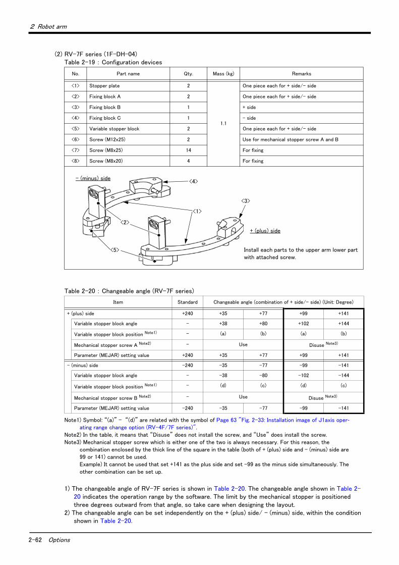
2-62 Options
2 Robot arm
(2) RV-7F series (1F-DH-04)Table 2-19 : Configuration devices
Table 2-20 : Changeable angle (RV-7F series)
1) The changeable angle of RV-7F series is shown in Table 2-20. The changeable angle shown in Table 2-20 indicates the operation range by the software. The limit by the mechanical stopper is positioned three degrees outward from that angle, so take care when designing the layout.
2) The changeable angle can be set independently on the + (plus) side/ - (minus) side, within the condition shown in Table 2-20.
No. Part name Qty. Mass (kg) Remarks
<1> Stopper plate 2
1.1
One piece each for + side/- side
<2> Fixing block A 2 One piece each for + side/- side
<3> Fixing block B 1 + side
<4> Fixing block C 1 - side
<5> Variable stopper block 2 One piece each for + side/- side
<6> Screw (M12x25) 2 Use for mechanical stopper screw A and B
<7> Screw (M8x25) 14 For fixing
<8> Screw (M8x20) 4 For fixing
Item Standard Changeable angle (combination of + side/- side) (Unit: Degree)
+ (plus) side +240 +35 +77 +99 +141
Variable stopper block angle - +38 +80 +102 +144
Variable stopper block position Note1)
Note1) Symbol: “(a)” - “(d)” are related with the symbol of Page 63 "Fig. 2-33: Installation image of J1axis oper-ating range change option (RV-4F/7F series)".
- (a) (b) (a) (b)
Mechanical stopper screw A Note2)
Note2) In the table, it means that “Disuse” does not install the screw, and “Use” does install the screw.
- Use Disuse Note3)
Note3) Mechanical stopper screw which is either one of the two is always necessary. For this reason, the combination enclosed by the thick line of the square in the table (both of + (plus) side and - (minus) side are 99 or 141) cannot be used. Example) It cannot be used that set +141 as the plus side and set -99 as the minus side simultaneously. The other combination can be set up.
Parameter (MEJAR) setting value +240 +35 +77 +99 +141
- (minus) side -240 -35 -77 -99 -141
Variable stopper block angle - -38 -80 -102 -144
Variable stopper block position Note1) - (d) (c) (d) (c)
Mechanical stopper screw B Note2) - Use Disuse Note3)
Parameter (MEJAR) setting value -240 -35 -77 -99 -141
<1>
<5>
<4>
<3>
<2>
Install each parts to the upper arm lower part with attached screw.
+ (plus) side
- (minus) side

2 Robot arm
Options 2-63
3) The operating range is changed with robot arm settings and parameter settings. Refer to the separate "Instruction Manual/ROBOT ARM SETUP & MAINTENANCE" or "Instruction Manual/Detailed Explana-tion of Functions and Operations" for details.
(3) Installation image (RV-4F/7F series)
Fig.2-33 : Installation image of J1axis operating range change option (RV-4F/7F series)
[Example] In the RV-7F series, when limiting the +side to +35 degree, and the -side to -141 degree, install as following.Variable stopper block: Installs in the position of (a), and the position of (c).Mechanical stopper screw A: Install.Mechanical stopper screw B: Do not install.
RV-4F/7F series installation image(Top-view of J1 axis)
<5> The installation position of Variable stopper block(a) - (d)
(d)
(c)
(a)
(b)
- (minus) side
+ (plus) side
Mechanical stopper screw A
Mechanical stopper screw B
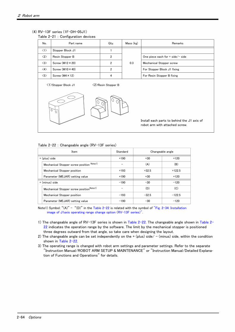
2-64 Options
2 Robot arm
(4) RV-13F series (1F-DH-05J1)Table 2-21 : Configuration devices
Table 2-22 : Changeable angle (RV-13F series)
1) The changeable angle of RV-13F series is shown in Table 2-22. The changeable angle shown in Table 2-22 indicates the operation range by the software. The limit by the mechanical stopper is positioned three degrees outward from that angle, so take care when designing the layout.
2) The changeable angle can be set independently on the + (plus) side/ - (minus) side, within the condition shown in Table 2-22.
3) The operating range is changed with robot arm settings and parameter settings. Refer to the separate "Instruction Manual/ROBOT ARM SETUP & MAINTENANCE" or "Instruction Manual/Detailed Explana-tion of Functions and Operations" for details.
No. Part name Qty. Mass (kg) Remarks
<1> Stopper Block J1 1
0.3
<2> Resin Stopper B 2 One piece each for + side/- side
<3> Screw (M12×20) 2 Mechanical Stopper screw
<4> Screw (M10×40) 2 For Stopper Block J1 fixing
<5> Screw (M4×12) 4 For Resin Stopper B fixing
Item Standard Changeable angle
+ (plus) side +190 +30 +120
Mechanical Stopper screw position Note1)
Note1) Symbol: “(A)” - “(D)” in the Table 2-22 is related with the symbol of "Fig. 2-34: Installation image of J1axis operating range change option (RV-13F series)".
- (A) (B)
Mechanical Stopper position +193 +32.5 +122.5
Parameter (MEJAR) setting value +190 +30 +120
+ (minus) side -190 -30 -120
Mechanical Stopper screw positionNote1) - (D) (C)
Mechanical Stopper position -193 -32.5 -122.5
Parameter (MEJAR) setting value -190 -30 -120
<1>Stopper Block J1 <2>Resin Stopper B
Install each parts to behind the J1 axis of robot arm with attached screw.
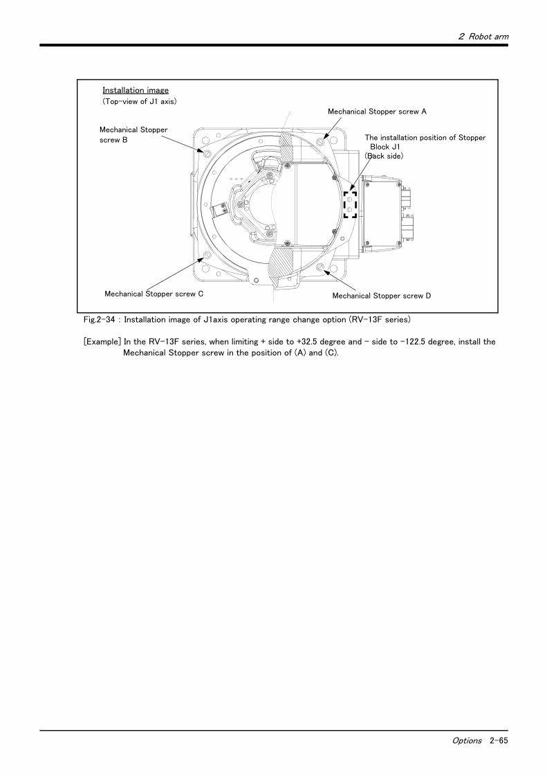
2 Robot arm
Options 2-65
Fig.2-34 : Installation image of J1axis operating range change option (RV-13F series)
[Example] In the RV-13F series, when limiting + side to +32.5 degree and - side to -122.5 degree, install the Mechanical Stopper screw in the position of (A) and (C).
The installation position of Stopper Block J1
(Back side)
Mechanical Stopper screw A
Mechanical Stopper screw B
Mechanical Stopper screw D
Installation image(Top-view of J1 axis)
Mechanical Stopper screw C
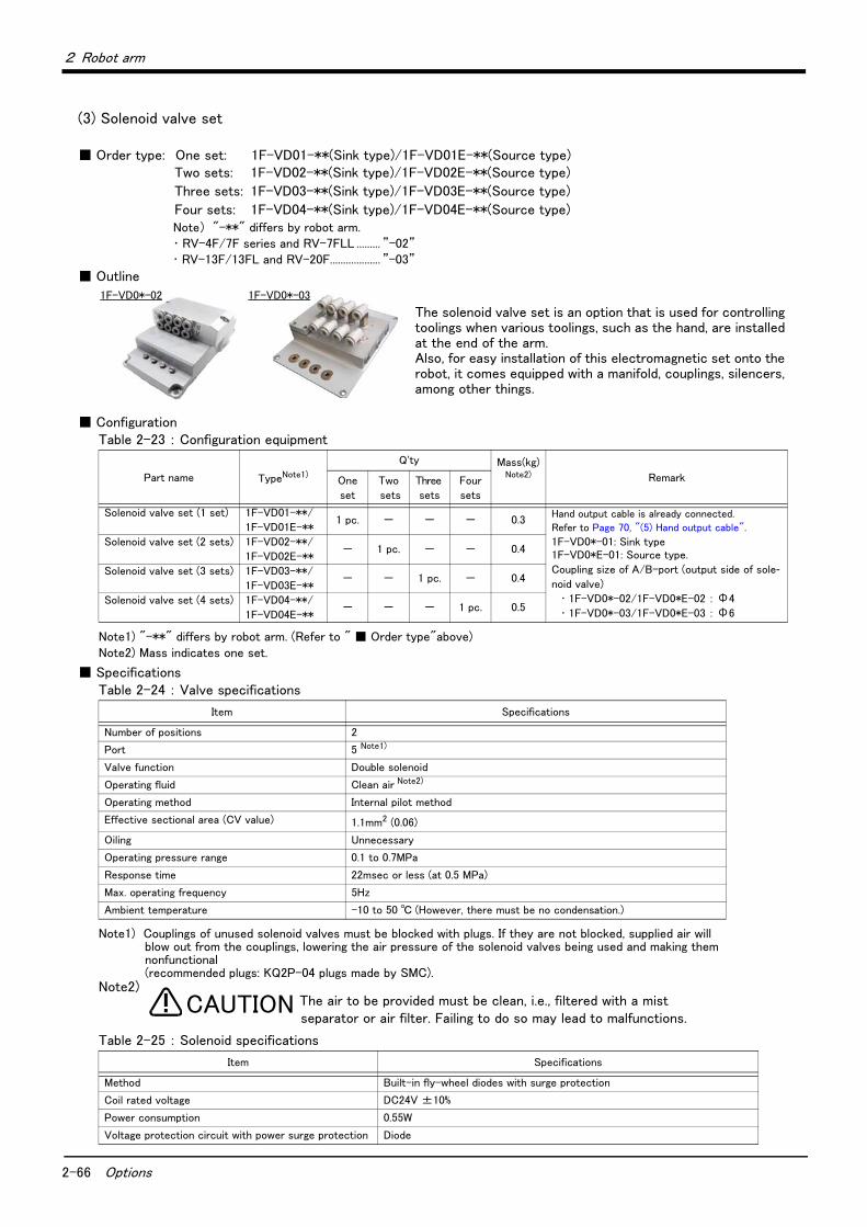
2-66 Options
2 Robot arm
(3) Solenoid valve set
■ Order type: One set: 1F-VD01-**(Sink type)/1F-VD01E-**(Source type)Two sets: 1F-VD02-**(Sink type)/1F-VD02E-**(Source type)
Three sets: 1F-VD03-**(Sink type)/1F-VD03E-**(Source type)
Four sets: 1F-VD04-**(Sink type)/1F-VD04E-**(Source type)Note) "-**" differs by robot arm. ・ RV-4F/7F series and RV-7FLL ......... ”-02”・ RV-13F/13FL and RV-20F................... ”-03”
■ Outline
The solenoid valve set is an option that is used for controlling toolings when various toolings, such as the hand, are installed at the end of the arm. Also, for easy installation of this electromagnetic set onto the robot, it comes equipped with a manifold, couplings, silencers, among other things.
■ ConfigurationTable 2-23 : Configuration equipment
■ SpecificationsTable 2-24 : Valve specifications
Table 2-25 : Solenoid specifications
Part name TypeNote1)
Note1) "-**" differs by robot arm. (Refer to " ■ Order type"above)
Q'ty Mass(kg)Note2)
Note2) Mass indicates one set.
RemarkOne
set
Two
sets
Three
sets
Four
sets
Solenoid valve set (1 set) 1F-VD01-**/
1F-VD01E-**1 pc. - - - 0.3
Hand output cable is already connected.
Refer to Page 70, "(5) Hand output cable".
1F-VD0*-01: Sink type1F-VD0*E-01: Source type.
Coupling size of A/B-port (output side of sole-noid valve)
・ 1F-VD0*-02/1F-VD0*E-02 : Φ4
・ 1F-VD0*-03/1F-VD0*E-03 : Φ6
Solenoid valve set (2 sets) 1F-VD02-**/
1F-VD02E-**- 1 pc. - - 0.4
Solenoid valve set (3 sets) 1F-VD03-**/
1F-VD03E-**- - 1 pc. - 0.4
Solenoid valve set (4 sets) 1F-VD04-**/
1F-VD04E-**- - - 1 pc. 0.5
Item Specifications
Number of positions 2
Port 5 Note1)
Note1) Couplings of unused solenoid valves must be blocked with plugs. If they are not blocked, supplied air will blow out from the couplings, lowering the air pressure of the solenoid valves being used and making them nonfunctional (recommended plugs: KQ2P-04 plugs made by SMC).
Valve function Double solenoid
Operating fluid Clean air Note2)
Note2)
Operating method Internal pilot method
Effective sectional area (CV value) 1.1mm2 (0.06)
Oiling Unnecessary
Operating pressure range 0.1 to 0.7MPa
Response time 22msec or less (at 0.5 MPa)
Max. operating frequency 5Hz
Ambient temperature -10 to 50 ℃ (However, there must be no condensation.)
Item Specifications
Method Built-in fly-wheel diodes with surge protection
Coil rated voltage DC24V ±10%
Power consumption 0.55W
Voltage protection circuit with power surge protection Diode
1F-VD0*-02 1F-VD0*-03
CAUTION The air to be provided must be clean, i.e., filtered with a mist separator or air filter. Failing to do so may lead to malfunctions.

2 Robot arm
Options 2-67
Fig.2-35 : Outline dimensional drawing (1F-VD0*-02/1F-VD0*E-02)
SOL1A
SOL1B
SOL2A
SOL2B
White
A3
<GR1>
A4
A1A2
B3B4
B1B2
GR1
GR2
+24V (COM)
Reserve
Reserve
Reserve
GR3
GR4
Black
Red
Black
Red
Black
Red
Black
Red
SOL3A
SOL3B
SOL4A
SOL4B
White
A3
<GR2>
A4
A1A2
B3B4
B1B2
GR5
GR6
+24V (COM)
Reserve
GR7
GR8
Black
Red
Black
Red
Black
Red
Black
Red
Reserve
Reserve
<Source type><Sink type>Connector name
SOL1A
SOL1B
SOL2A
SOL2B
A3
<GR1>
A4
A1A2
B3B4
B1B2
GR1
GR2
24V (RG)
Reserve
GR3
GR4
Reserve
Reserve
White
Black
Red
Black
Red
Black
Red
Black
Red
SOL3A
SOL3B
SOL4A
SOL4B
A3
<GR2>
A4
A1A2
B3B4
B1B2
GR5
GR6
24V (RG)
Reserve
GR7
GR8
Reserve
Reserve
White
Black
Red
Black
Red
Black
Red
Black
Red
Connector name
1
2
3
4
5
6
7
8
A
B
60 3.5
74.5
4.5
116
126
10 6.8
41.5
4-φ
4.5
40 13.2
21 11.5
GR2
GR1
<7><8>
<1>
<2>
<6>
<9>
<4>
<3>
<5>
Part no. Part name 1 sets 2 sets 3 sets 4 sets Specifications
<1> Solenoid valve 1 2 3 4
<2> Manifold block 1 1 1 1
<3> Quick coupling 8 8 8 8 φ4
<4> Housing 1 1 1 1
<5> Quick coupling 2 2 2 2 φ6
<6> Plug 4 4 4 4
<7> Connector 1 1 2 2 1-1318115-4
<8> Contact 3 5 8 10 1318112-1
<9> Installation screw 4 4 4 4 M4×12
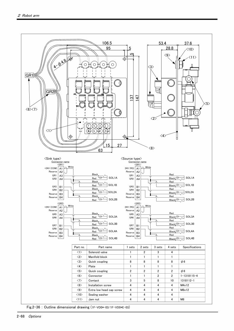
2-68 Options
2 Robot arm
Fig.2-36 : Outline dimensional drawing (1F-VD0*-03/1F-VD0*E-03)
SOL1A
SOL1B
SOL2A
SOL2B
White
A3
<GR1>
A4
A1A2
B3B4
B1B2
GR1
GR2
+24V (COM)
Reserve
Reserve
Reserve
GR3
GR4
Black
Red
Black
Red
Black
Red
Black
Red
SOL3A
SOL3B
SOL4A
SOL4B
White
A3
<GR2>
A4
A1A2
B3B4
B1B2
GR5
GR6
+24V (COM)
Reserve
GR7
GR8
Black
Red
Black
Red
Black
Red
Black
Red
Reserve
Reserve
<Source type><Sink type>Connector name
SOL1A
SOL1B
SOL2A
SOL2B
A3
<GR1>
A4
A1A2
B3B4
B1B2
GR1
GR2
24V (RG)
Reserve
GR3
GR4
Reserve
Reserve
White
Black
Red
Black
Red
Black
Red
Black
Red
SOL3A
SOL3B
SOL4A
SOL4B
A3
<GR2>
A4
A1A2
B3B4
B1B2
GR5
GR6
24V (RG)
Reserve
GR7
GR8
Reserve
Reserve
White
Black
Red
Black
Red
Black
Red
Black
Red
Connector name
Part no. Part name 1 sets 2 sets 3 sets 4 sets Specifications
<1> Solenoid valve 1 2 3 4
<2> Manifold block 1 1 1 1
<3> Quick coupling 8 8 8 8 φ6
<4> Plate 1 1 1 1
<5> Quick coupling 2 2 2 2 φ6
<6> Connector 1 1 2 2 1-1318115-4
<7> Contact 3 5 8 10 1318112-1
<8> Installation screw 4 4 4 4 M4x12
<9> Extra low head cap screw 4 4 4 4 M8x12
<10> Sealing washer 4 4 4 4
<11> Jam nut 4 4 4 4 M8
106.595 5
5
4-φ
4.8
6315 27
137
147
GR2
GR1
53.4 37.628.8
<6><7>
<1>
<2>
<8>
<4>
<3>
<5>
<9>
<10>
<11>

2 Robot arm
Options 2-69
(4) Hand input cable
■ Order type: 1F-HC35S-02
■ Outline
The hand input cable is used for customer-designed pneumatic hands.
It is necessary to use this to receive the hand's open/close confirmation signals and grasping confirmation signals, at the controller.
One end of the cable connects to the connector for hand input signals, which is in the wrist section of the hand. The other end of the cable connected to the sensor inside the hand customer designed.
■ ConfigurationTable 2-26 : Configuration equipment
■ SpecificationsTable 2-27 : Specifications
Pin assign of the hand input cable is shown in Table 2-28.
Table 2-28 : Pin assign of hand input cable
[Caution] This option can be installed on clean-type, but its cleanliness is not under warranty.
Part name Type Qty. Mass (kg) Note1)
Note1) Mass indicates one set.
Remarks
Hand input cable 1F-HC35S-02 1 cable 0.2
Item Specifications Remarks
Size x cable core AWG#24 (0.2 mm2)×10 cores One-sided connector, one-sided cable bridging
Total length 1,000 mm
Color Connector Note1)
Note1) The connector shows the connector name connected to the robot-arm side.
Pin number: names Color Connector Note1) Pin number: names
Purple
OP1
A1: HC1 Yellow
OP3
A1: +24V
Brown A2: HC2 Green A2: +24G (RG)
Blue A3: HC3 - Reserved
Black A4: HC4 - Reserved
Red B1: HC5
White B2: HC6
Gray B3: HC7
Pink B4: HC8
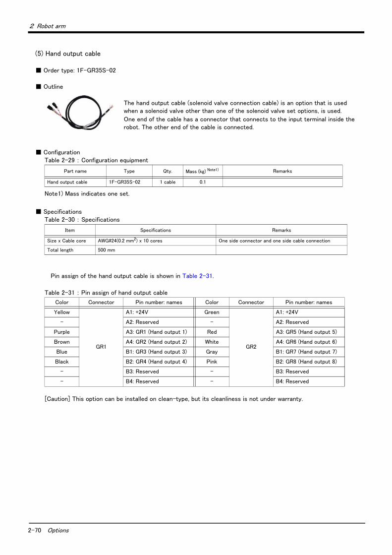
2-70 Options
2 Robot arm
(5) Hand output cable
■ Order type: 1F-GR35S-02
■ Outline
The hand output cable (solenoid valve connection cable) is an option that is used when a solenoid valve other than one of the solenoid valve set options, is used.
One end of the cable has a connector that connects to the input terminal inside the robot. The other end of the cable is connected.
■ ConfigurationTable 2-29 : Configuration equipment
■ SpecificationsTable 2-30 : Specifications
Pin assign of the hand output cable is shown in Table 2-31.
Table 2-31 : Pin assign of hand output cable
[Caution] This option can be installed on clean-type, but its cleanliness is not under warranty.
Part name Type Qty. Mass (kg) Note1)
Note1) Mass indicates one set.
Remarks
Hand output cable 1F-GR35S-02 1 cable 0.1
Item Specifications Remarks
Size x Cable core AWG#24(0.2 mm2) x 10 cores One side connector and one side cable connection
Total length 500 mm
Color Connector Pin number: names Color Connector Pin number: names
Yellow
GR1
A1: +24V Green
GR2
A1: +24V
- A2: Reserved - A2: Reserved
Purple A3: GR1 (Hand output 1) Red A3: GR5 (Hand output 5)
Brown A4: GR2 (Hand output 2) White A4: GR6 (Hand output 6)
Blue B1: GR3 (Hand output 3) Gray B1: GR7 (Hand output 7)
Black B2: GR4 (Hand output 4) Pink B2: GR8 (Hand output 8)
- B3: Reserved - B3: Reserved
- B4: Reserved - B4: Reserved
2 Robot arm
Options 2-71
(6) Hand curl tube
■ Order type: RV-4F/7F series, RV-7FLL ............One set: 1E-ST0402CTwo sets: 1E-ST0404C
Three sets: 1E-ST0406C
Four sets: 1E-ST0408C
RV-13F/13FL/20F..............................One set: 1N-ST0602C
Two sets: 1N-ST0604C
Three sets: 1N-ST0606C
Four sets: 1N-ST0608C
■ Outline
The hand curl tube is a curl tube for the pneumatic hand.
■ ConfigurationTable 2-32 : Configuration equipment
■ SpecificationsTable 2-33 : Specifications
Part name Type Qty. Mass(kg)Note1)
Note1) Mass indicates one set.
Remarks
For RV-4F/7F series, RV-7FLL
Hans curl tube (One set: 2 pcs.) 1E-ST0402C 1 pc. 0.1 φ4 tube, 2pcs.
Hans curl tube (Two sets: 4 pcs.) 1E-ST0404C 1 pc. 0.1 φ4 tube, 4pcs.
Hans curl tube (Three sets: 6 pcs.) 1E-ST0406C 1 pc. 0.1 φ4 tube, 6pcs.
Hans curl tube (Four sets: 8 pcs.) 1E-ST0408C 1 pc. 0.1 φ4 tube, 8pcs.
For RV-13F/13FL/20F
Hans curl tube (One set: 2 pcs.) 1N-ST0602C 1 pc. 0.1 φ6 tube, 2pcs.
Hans curl tube (Two sets: 4 pcs.) 1N-ST0604C 1 pc. 0.1 φ6 tube, 4pcs.
Hans curl tube (Three sets: 6 pcs.) 1N-ST0606C 1 pc. 0.1 φ6 tube, 6pcs.
Hans curl tube (Four sets: 8 pcs.) 1N-ST0608C 1 pc. 0.1 φ6 tube, 8pcs.
Item Specifications
Material Urethane
Size 1E-ST040*C : Outside diameterφ4× Inside diameterφ2.5
1N-ST060*C : Outside diameterφ6× Inside diameterφ4

2-72 Options
2 Robot arm
Fig.2-37 : Outline dimensional drawing
[Caution] This option can be installed on clean-type, but its cleanliness is not under warranty.
600
(ツーリング側)
250
300
(ロボット側)
250
(ツーリング側)
180
200
(ロボット側)
RV-13F/13FL/20F: 1N-ST060*C (φ6)
RV-4F/7F series, RV-7FLL: 1E-ST040*C (φ4)
(Tooling side)
(Robot side)
(Tooling side)
(Robot side)

2 Robot arm
Options 2-73
(7) Forearm external wiring set/ Base external wiring set
■ Order typeForearm external wiring set: 1F-HB01S-01 (Hand input signals, force sensor and vision sensor)
1F-HB02S-01 (Force sensor and vision-sensor)
Base external wiring set: 1F-HA01S-01 (Force sensor and vision-sensor)
1F-HA02S-01 (Force sensor and vision-sensor)
Note) In the Internal wiring and piping specification, the corresponding base external wiring set is attached.
■ Outline
The Forearm external wiring set and the Base external wiring set are used to pull out the hand input signal cables and communication cables etc. from the underneath of the forearm and the side of the base.
This option consists of the cable clamp box and the cable for hand input signals or the cable for communication.1) Hand input cable
The hand input cable of the option (equivalent of 1F-HC35C-02) is installed. Connect to the connectors OP1 and OP3 of the hand input cable, which is built into the forearm. Connect the user connection side of pulled-out cable to the tools etc, and input the signals.
2) Communication cablePulls out the cable which attached the connector for connecting with vision sensor etc. The pulled out cables from the underneath of the forearm are connected with a vision sensor camera, or a force sensor. The pulled out cables from the side of the base are connected with a vision sensor controller, or a force sensor interface. (To connect to a force sensor, use the adaptor cable that is supplied in the force sensor option.)
■ ConfigurationTable 2-34 : Configuration equipment
■ SpecificationThe kind of cable which can be pulled out for each option is shown in Table 2-35. Because to pull out the cable
of the same purpose also as the forearm side and the base side, you should use the option in pair shown in "the pairing (recommendation)" of the table. And, each wiring system figure is shown after the following page.
Table 2-35 : Internal wiring and piping specification types
Table 2-36 : Color of the wire and signal name (hand input cable)
Part name Type Qty. Remarks
Forearm external wiring set 1F-HB01S-01 Either one
pc.1F-HB02S-01
Base external wiring set 1F-HA01S-01 Either one
pc.1F-HA02S-01
Pairing
(recommendation)Option type
Cable length
(mm) Note1)
Note1) The length from the cable clamp box to the connector.
Wiring (cable for the connection to each equipment)
Hand input signal Note2)
Note2) Although the connector is attached to the customer wiring side of hand input cable, the connector can be cut, and con-nect to the tool of the customer preparation. The color and signal name of the wire are shown in Table 2-36.
Vision sensor camera Force sensor unit
11F-HB01S-01 (Forearm) 1,000 eight points 1 Either one unit
1F-HA01S-01 (Base) 500 Not available 1 Either one unit
21F-HB02S-01 (Forearm) 1,000 Not available 1 1
1F-HA02S-01 (Base) 500 Not available 1 1
ColorSignal name
Connector(HC)
ColorSignal name
Connector(HC)
ColorSignal name
Connector(HC)
ColorSignal name
Connector(HC)
Violet HC1 A1 Brown HC2 A2 Blue HC3 A3 Black HC4 A4
Red HC5 B1 White HC6 B2 Gray HC7 B3 Pink HC8 B4
Yellow +24V A6 Green +24G(RG) B6 -
Forearm
Option attachment positions
Base(Opposite side)
*The figure is an exam-ple.

2-74 Options
2 Robot arm
1) Wiring system diagram (1F-H*01S-01: Hand input signals, force sensor and vision sensor)
Fig.2-38 : Wiring system diagram (1F-H*01S-01)
白 A1A2A3A4B1B2B3B4
コントローラ
ロボット本体配線中継ボード
<+24V(COM)>
<GR 1><GR 2><GR 3><GR 4>
A1A2A3A4B1B2B3B4
<+24V(COM)>
<GR 5><GR 6><GR 7><GR 8>
ハンド信号出力用コネクタ(GR2コネクタ)
ハンド信号出力用コネクタ(GR1コネクタ)
白
黒
白
黒
黒
白
黒
白
黒
<+24V><+24G(RG)><HC 1> : :<HC 8>
<TXRXH><TXRXL>
GR1
GR2
φ6クイック継手
1次配管エアホース
φ6ホース
φ6ホース
φ6クイック継手
AIR IN
RETURN
フォアアーム内 ベース部
φ8クイック継手
<HC1><HC2><HC3><HC4><HC5><HC6><HC7><HC8>
A1A2A3A4B1B2B3B4
A1A2B1B2
<+24V><+24G(RG)><+24V><+24G(RG)>
A1A2B1B2
A1A2A3A4B1B2B3B4
OP3
OP1
OP2
OP4
100BASETXイーサネットケーブル
A1A2A3A4B1B2B3B4
電磁弁セット(オプション)
白橙橙白緑緑青白青白茶茶
オイルミスト仕様(加圧)クリーン仕様(吸引)のみ
<TXRXH><TXRXL><+24(RG)><+24V>
A15A16A17A18B15B16B17B18
A19A20B19B20
A9A10B9B10
A11A12A13A14B11B12B13B14
A1A2A3A4
A1A2A3A4B1B2B3B4
LAN
Note 1) When using a force sensor, use the supplied adaptor cable to connect to the force sensor option.
Hand input signal
Vision-sensor camera. (Ethernet)
Force sensor Note 1)
Option (Forearm):
1F-HB01S-01
Cable clamp
Reserved
Connects with the force sensor
interface Note 1)
Connects with the vision-sensor controller
Option (Base):
1F-HA01S-01
Hand output signal
Connect to the optional solenoid
valve set directly
or
Connect with customer's tool
drive equipment (solenoid valve,
etc), by the optional hand output
cable.
Hand signal output connector (GR1)
White
WhiteBlackWhiteBlack
Hand signal output connector (GR2)
Black
WhiteBlackWhiteBlack
Robo
t ar
m w
irin
g re
lay
boar
d
Contr
olle
r
Primary piping pneumatic hose
Solenoid valve set (Option)
φ6 quick coupling φ6 quick coupling
φ6 hose
φ6 hose
φ8 quick couplingVACCUM : Clean specificationAIR PURGE: Oil-mist specification
Fore arm Base
White/Orange
Orange
White/Green
Green
Blue
White/Blue
White/Brown
Brown
100 BASETX Either net cable
LAN
LAN
RIO
E ・ F1E ・ F1
HC
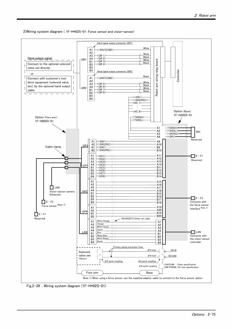
2 Robot arm
Options 2-75
2)Wiring system diagram ( 1F-H*02S-01: Force sensor and vision-sensor)
Fig.2-39 : Wiring system diagram (1F-H*02S-01)
白 A1A2A3A4B1B2B3B4
コントローラ
ロボット本体配線中継ボード
<+24V(COM)>
<GR 1><GR 2><GR 3><GR 4>
A1A2A3A4B1B2B3B4
<+24V(COM)>
<GR 5><GR 6><GR 7><GR 8>
ハンド信号出力用コネクタ(GR2コネクタ)
ハンド信号出力用コネクタ(GR1コネクタ)
白
黒
白
黒
黒
白
黒
白
黒
<+24V><+24G(RG)><HC 1> : :<HC 8>
<TXRXH><TXRXL>
GR1
GR2
φ6クイック継手
1次配管エアホース
φ6ホース
φ6ホース
φ6クイック継手
AIR IN
RETURN
フォアアーム内 ベース部
φ8クイック継手
<HC1><HC2><HC3><HC4><HC5><HC6><HC7><HC8>
A1A2A3A4B1B2B3B4
A1A2B1B2
<+24V><+24G(RG)><+24V><+24G(RG)>
A1A2B1B2
A1A2A3A4B1B2B3B4
OP3
OP1
OP2
OP4
100BASETXイーサネットケーブル
A1A2A3A4B1B2B3B4
電磁弁セット(オプション)
白橙橙白緑緑青白青白茶茶
オイルミスト仕様(加圧)クリーン仕様(吸引)のみ
<TXRXH><TXRXL><+24(RG)><+24V>
A15A16A17A18B15B16B17B18
A19A20B19B20
A9A10B9B10
A11A12A13A14B11B12B13B14
A1A2A3A4
A1A2A3A4B1B2B3B4
LAN
Vision-sensor camera. (Ethernet)
Force sensor Note 1)
Reserved
Connects with the force sensor
interface Note 1)
Reserved
Connects with the vision-sensor controller
Reserved
Option (Fore arm):
1F-HB02S-01
Option (Base):
1F-HA02S-01
Hand output signal
Connect to the optional solenoid
valve set directly
or
Connect with customer's tool
drive equipment (solenoid valve,
etc), by the optional hand output
cable.
Hand signal output connector (GR1)
White
WhiteBlackWhiteBlack
Hand signal output connector (GR2)
Black
WhiteBlackWhiteBlack
Robo
t ar
m w
irin
g re
lay
boar
d
Contr
olle
r
Cable clamp
Primary piping pneumatic hose
Solenoid valve set (Option)
φ6 quick coupling φ6 quick coupling
φ6 hose
φ6 hose
φ8 quick couplingVACCUM : Clean specificationAIR PURGE: Oil-mist specification
Fore arm Base
White/Orange
Orange
White/Green
Green
Blue
White/Blue
White/Brown
Brown
100 BASETX Either net cable
Note 1) When using a force sensor, use the supplied adaptor cable to connect to the force sensor option.
E ・ F1
E ・ F2
RIO
E ・ F1
E ・ F2
LAN
LAN
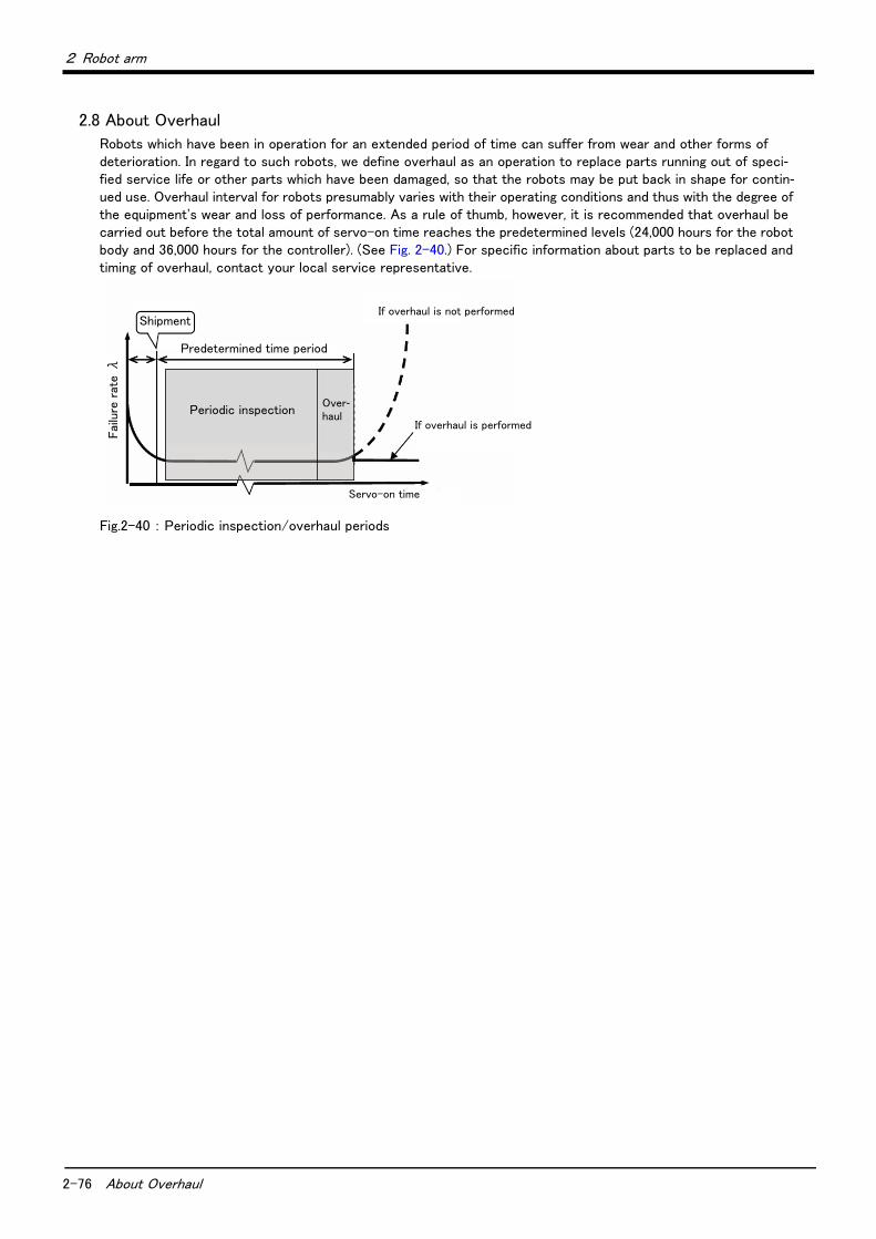
2-76 About Overhaul
2 Robot arm
2.8 About Overhaul
Robots which have been in operation for an extended period of time can suffer from wear and other forms of deterioration. In regard to such robots, we define overhaul as an operation to replace parts running out of speci-fied service life or other parts which have been damaged, so that the robots may be put back in shape for contin-ued use. Overhaul interval for robots presumably varies with their operating conditions and thus with the degree of the equipment's wear and loss of performance. As a rule of thumb, however, it is recommended that overhaul be carried out before the total amount of servo-on time reaches the predetermined levels (24,000 hours for the robot body and 36,000 hours for the controller). (See Fig. 2-40.) For specific information about parts to be replaced and timing of overhaul, contact your local service representative.
Fig.2-40 : Periodic inspection/overhaul periods
Shipment
Fai
lure
rat
e λ
Predetermined time period
If overhaul is performed
Servo-on time
If overhaul is not performed
Periodic inspectionOver-haul

2 Robot arm
Maintenance parts 2-77
2.9 Maintenance parts
The consumable parts used in the robot arm are shown in Table 2-37. Purchase these parts from the designated maker or dealer when required. Some Mitsubishi-designated parts differ from the maker's standard parts. Thus, confirm the part name, robot arm and controller serial No. and purchase the parts from the dealer.
Table 2-37 : Consumable part list
No. Part name Type Note1)
Note1) Confirm the robot arm serial No., and contact the dealer or service branch of Mitsubishi Electric Co., for the type.
Usage place Qty. Supplier
1 Grease Reduction gears of each axis As neededMitsubishi Electric
2 Lithium battery ER6 Inside the CONBOX cover 3 pcs.

3-78 Standard specifications
3Controller
3 Controller
3.1 Standard specifications
Table 3-1 : Specifications of controller
Item Unit Specification Remarks
Type CR750- □ VD-1
CR750-07VLD-1
" □ "in type name shows the load
(04, 07, 13 or 20) of robot arm.
CR750-07VLD-1 controller is only for
RV-7FLL.
Number of control axis Simultaneously 6
Memory
capacity
Programmed positions point 39,000
No. of steps step 78,000
Number of program 512
Robot language MELFA-BASIC V
Teaching method Pose teaching method, MDI method Note1)
Note1) Pose teaching method: The method to register the current position of the robot arm.MDI method: The method to register by inputting the numerical value Immediate.
External input and output
Input and output point 0/0 Max. 256/256 by option
Dedicated input/outputAssigned with general-purpose
input/output
The signal number of "STOP" input
signals is fixing.
Hand open/close input/output point 8/8 Built-in
Emergency stop input point 1 Dual line
Door switch input point 1 Dual line
Enabling device input point 1 Dual line
Emergency stop output point 1 Dual line
Mode output point 1 Dual line
Robot error output point 1 Dual line
Addition axis synchronization point 1 Dual line
Interface RS-422 port 1 Only for T/B
Ethernet port 1 10BASE-T/100BASE-Tx
USB port 1Ver.2.0 FullSpeed
Only device function
Additional axis interface Channel 1SSCNET III (Connects with MR-J3-
BS, MR-J4-B series)
Tracking interface Channel 2
Option slot slot 2 For option interface
Power
source
Input voltage range V RV-4F series:
Single phase AC180 to 253
RV-7F/13F seriesNote2) :
Three phase AC180 to 253, or
Single phase AC207 to 253
Note2) Both the three phase power supply and the single phase power supply can use this product according to voltage condi-tions.
Power capacity kVA RV-4F series : 1.0
RV-7F series : 2.0
RV-13F series : 3.0
Does not include rush current Note3)
Power supply frequency Hz 50/60
Outline dimensions Note4) mm 430(W) x 425(D) x 174(H) Excluding protrusions
Mass kg Approx. 18
Construction Self-contained floor type, Opened type.Installation vertically or horizontally
IP20 Note5)
Operating temperature range ℃ 0 to 40
Ambient humidity %RH 45 to 85 Without dew drops
Grounding Ω 100 or less 100Ωor less (class D grounding)Note6)
Paint color Dark gray Equivalent to Munsell: 3.5PB3.2/0.8
3Controller
Protection specifications and operating supply 3-79
3.2 Protection specifications and operating supply
A protection method complying with the IEC Standard IP20 (Opened type) is adopted for the controller.The IEC IP symbols refer only to the degree of protection between the solid and the fluids, and don't indicated that any special protection has been constructed for the prevention against oil and water.
【Information】
・ The IEC IP20
It indicates the protective structure that prevents an iron ball 12 0+0.05mm diameter, which is being pressed with
the power of 3.1 kg±10%, from going through the opening in the outer sheath of the supplied equipment.
Refer to the section Page 151, "6.2 Working environment" for details on the working environment.
Note3) The power capacity is the rating value for normal operation. The power capacity does not include the rush current whenthe power is turned ON. The power capacity is a guideline and the actual operation is affected by the input power volt-age. The short circuit breaker should use the following.* Operate by the current leakage under the commercial frequency domain (50-60Hz). If sensitive to the high frequency
ingredient, it will become the cause in which below the maximum leak current value carries out the trip.Note4) Refer to Page 82, "3.4 Outside dimensions/Installation dimensions" for details.Note5) This controller is standard specification. (Refer to Page 79, "3.2 Protection specifications and operating supply".)Note6) The robot must be grounded by the customer.
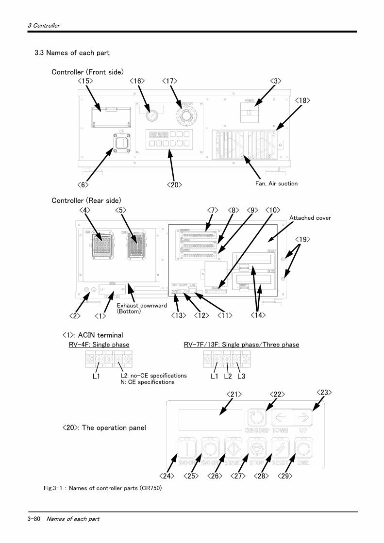
3-80 Names of each part
3 Controller
3.3 Names of each part
Fig.3-1 : Names of controller parts (CR750)
Controller (Front side)<15>
<6>
<16> <17> <3>
<18>
<20> Fan, Air suction
<7> <10><8> <9>
<1><2>
<19>
Attached cover
Controller (Rear side)
Exhaust downward(Bottom)
<5><4>
<13> <12> <11> <14>
L1 L2: no-CE specificationsN: CE specifications
<1>: ACIN terminalRV-4F: Single phase
<20>: The operation panel
<24> <25> <26> <27> <28> <29>
<23><22><21>
L1 L3L2
RV-7F/13F: Single phase/Three phase
3 Controller
Names of each part 3-81
<1> ACIN terminal ................................................The terminal box for AC power source (single phase or single phase/three phase, AC200V) input. (Inner side of a cover)Note)When using the RV-4F series, connect the primary power supply to
L1 and L2 terminal. When using the RV-7F/13F series, connect the primary power supply to L1, L2 and L3 terminal when using the three phase primary power supply, and connect the primary power supply to L1 and L3 terminal when using the single phase primary power supply.
<2> PE terminal .....................................................The screw for grounding of the cable. (M4 screw x 2 place)<3> Power switch .................................................This turns the control power ON/OFF<4> Machine cable connector (motor signal) (CN1)
Connect with the CN1 connector of the robot arm.<5> Machine cable connector (motor power) (CN2)
Connect with the CN2 connector of the robot arm.<6> T/B connection connector (TB) ...........This is a dedicated connector for connecting the T/B. When not using T/
B, connect the attached dummy connector.<7><8><9><10> CNUSR connector ..............The connector for input/ output connection dedicated for robot. (a plug
connector attached)<7>: CNUSR11, <8>: CNUSR12, <9>: CNUSR13, <10>: CNUSR2
<11> LAN connector (LAN)......................... For LAN connection<12> ExtOPT connector (ExtOPT) .......... Connect the cable for addition axis control.<13> RIO connector (RIO) ........................... Connect the extension parallel input/output unit.<14> Option slot (SLOT1, SLOT2)........... Install the interface optional. (Install the cover, when not using.)<15> Interface cover ...................................... USB interface and battery are mounted.<16> Mode key switch ................................... This key switch changes the robot's operation mode.
AUTOMATIC ..........Operations from the controller or external equipment are valid. Operations for which the operation mode must be at the external device or T/B are not possible. (Exclude the start of automatic operation.)
MANUAL ..................When the T/B is valid, only operations from the T/B are valid. Operations for which the operation mode must be at the external device or controller are not possible.
<17> Emergency stop switch...................... This switch stops the robot in an emergency state. The servo turns OFF.<18> Filter cover.............................................. There is an air filter inside the cover.<19> Grounding terminal............................... The grounding terminal for connecting cables of option card. (M3 screw x 2
places)<20> Operation panel ..................................... The operation panel for servo ON/OFF, START/STOP the program etc.<21> Display panel (STATUS.NUMBER) ........... The alarm No., program No., override value (%), etc., are displayed.<22> CHNGDISP button ............................... This button changes the details displayed on the display panel in the order
of "Override" → "Program No." → "Line No.".<23> UP/DOWN button............................... This scrolls up or down the details displayed on the "STATUS. NUMBER"
display panel.<24> SVO.ON button ..................................... This turns ON the servo power. (The servo turns ON.)<25> SVO.OFF button.................................. This turns OFF the servo power. (The servo turns OFF.)<26> START button........................................ This executes the program and operates the robot. The program is run
continuously.<27> STOP button .......................................... This stops the robot immediately. The servo does not turn OFF.<28> RESET button ........................................ This resets the error. This also resets the program's halted state and
resets the program.<29> END button ............................................. This stops the program being executed at the last line or END statement.
Use the network equipments (personal computer, USB hub, LAN hub, etc) confirmed by manufacturer. The thing unsuitable for the FA environment (related with conformity, temperature or noise) exists in the equipments connected to USB. When using network equipment, measures against the noise, such as measures against EMI and
the addition of the ferrite core, may be necessary. Please fully confirm the operation by customer. Guarantee and maintenance of the equipment on the market (usual office automation equipment) cannot be performed.
Caution

3-82 Outside dimensions/Installation dimensions
3 Controller
3.4 Outside dimensions/Installation dimensions
3.4.1 Outside dimensions
Fig.3-2 : Outside dimensions of controller (CR750)
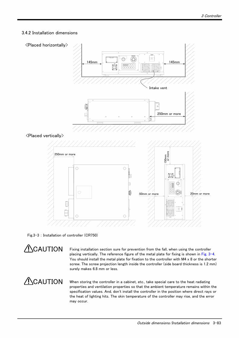
3 Controller
Outside dimensions/Installation dimensions 3-83
3.4.2 Installation dimensions
Fig.3-3 : Installation of controller (CR750)
Fixing installation section sure for prevention from the fall, when using the controller placing vertically. The reference figure of the metal plate for fixing is shown in Fig. 3-4.
You should install the metal plate for fixation to the controller with M4 x 8 or the shorter screw. The screw projection length inside the controller (side board thickness is 1.2 mm) surely makes 6.8 mm or less.
When storing the controller in a cabinet, etc., take special care to the heat radiating properties and ventilation properties so that the ambient temperature remains within the specification values. And, don't install the controller in the position where direct rays or the heat of lighting hits. The skin temperature of the controller may rise, and the error may occur.
150m
m以
上
50mm以上 20mm以上
250mm以上
145mm 145mm
250mm以上
吸気口
<Placed horizontally>
<Placed vertically>
Intake vent
250mm or more
50mm or more 20mm or more
150
mm
or
more
250mm or more
CAUTION
CAUTION

3-84 Outside dimensions/Installation dimensions
3 Controller
Fig.3-4 : Metal plate for fixation to placing vertically (Reference for CR750)
hole(Controller fixation hole)
hole
hole

3 Controller
External input/output 3-85
3.5 External input/output
3.5.1 Types(1) Dedicated input/output...............................These inputs and outputs carry out the robot remote operation and
status display.(2) General-purpose input/output.................These are inputs and outputs that the customer can program for
peripheral device control.(3) Hand input/output .........................................These are inputs and outputs related to the hand that the customer can
program.(4)Emergency stop/Door switch input.........The wiring for the safe security of the emergency stop etc. is shown in
on Page 89, "3.7 Emergency stop input and output etc." and on Page 144, "6.1.7 Examples of safety measures".
<For Reference>
Linking our GOT1000 Series (GT15) display equipment to the robot controller over the Ethernet permits you to control robot controller's input/output from a GOT (graphic operation terminal).

3-86 Dedicated input/output
3 Controller
3.6 Dedicated input/output
Show the main function of dedicated input/output in the Table 3-2. Refer to attached instruction manual "Detailed explanations of functions and operations" in the product for the other functions. Each parameter indi-cated with the parameter name is used by designated the signal No., assigned in the order of input signal No. and output signal No.
Table 3-2 : Dedicated input/output list
Parameter name
Input Note1) Output
Name Function Level Name Function
TEACHMD None Teaching mode out-put signal
Outputs that the teaching mode is
entered.
ATTOPMD None Automatic mode out-put signal
Outputs that the automatic mode is
entered.
ATEXTMD None Remote mode output
signal
Outputs that the remote mode is
entered.
RCREADY None Controller power ON
complete signal
Outputs that external input signals can
be received.
AUTOENA Automatic opera-tion enabled input
signal
Allows automatic operation.
L
Automatic operation
enabled output signal
Outputs the automatic operation
enabled state.
START Start input signal Starts all slots.E
Operating output sig-nal
Outputs that the slot is operating.
STOP Stop input signal Stops all slots.
The input signal No. is fixed to 0.
Note) Use the emergency stop
input for stop inputs related
to safety.
L
Wait output signal Outputs that the slot is temporarily
stopped.
STOP2 Stop input signal The program during operation is
stopped.
Unlike the STOP parameter,
change of the signal number is
possible.
Notes) Specification is the same as
the STOP parameter.
L
Wait output signal Outputs that the slot is temporarily
stopped.
Notes) Specification is the same as the
STOP parameter.
SLOTINIT Program reset input
signal
Resets the wait state.E
Program selection
enabled output signal
Outputs that the slot is in the program
selection enabled state.
ERRRESET Error reset input
signal
Resets the error state.E
Error occurring out-put signal
Outputs that an error has occurred.
CYCLE Cycle stop input
signal
Carries out cycle stop.E
In cycle stop opera-tion output signal
Outputs that the cycle stop is operat-ing.
SRVOFF Servo ON enabled
input signal
Turns the servo OFF for all mech-anisms.
LServo ON enabled
output signal
Outputs servo-on disable status.
(Echo back)
SRVON Servo ON input
signal
Turns the servo ON for all mecha-nisms.
EIn servo ON output
signal
Outputs the servo ON state.
IOENA Operation rights
input signal
Requests the operation rights for
the external signal control.L
Operation rights out-put signal
Outputs the operation rights valid state
for the external signal control.
MELOCK Machine lock input
signal
Sets/resets the machine lock
state for all mechanisms.E
In machine lock out-put signal
Outputs the machine lock state.
SAFEPOS Evasion point
return input signal
Requests the evasion point return
operation.E
In evasion point
return output signal
Outputs that the evasion point return
is taking place.
OUTRESET General-purpose
output signal reset
Resets the general-purpose output
signal.E None
EMGERRNone
Emergency stop out-put signal
Outputs that an emergency stop has
occurred.
S1START
:
S32START
Start input Starts each slot. E In operation outputOutputs the operating state for each
slot.
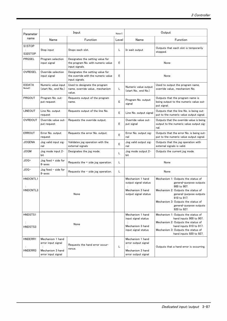
3 Controller
Dedicated input/output 3-87
S1STOP
:
S32STOP
Stop input Stops each slot. L In wait outputOutputs that each slot is temporarily
stopped.
PRGSEL Program selection
input signal
Designates the setting value for
the program No. with numeric value
input signals.
E None
OVRDSEL Override selection
input signal
Designates the setting value for
the override with the numeric value
input signals.
E None
IODATANote2)
Numeric value input
(start No., end No.)
Used to designate the program
name, override value., mechanism
value.
LNumeric value output
(start No., end No.)
Used to output the program name,
override value., mechanism No.
PRGOUT Program No. out-put request
Requests output of the program
name. EProgram No. output
signal
Outputs that the program name is
being output to the numeric value out-put signal.
LINEOUT Line No. output
request
Requests output of the line No.E Line No. output signal
Outputs that the line No. is being out-put to the numeric value output signal.
OVRDOUT Override value out-put request
Requests the override output.
E
Override value out-put signal
Outputs that the override value is being
output to the numeric value output sig-nal.
ERROUT Error No. output
request
Requests the error No. output.E
Error No. output sig-nal
Outputs that the error No. is being out-put to the numeric value output signal.
JOGENA Jog valid input sig-nal
Validates jog operation with the
external signalsE
Jog valid output sig-nal
Outputs that the jog operation with
external signals is valid.
JOGM Jog mode input 2-
bit
Designates the jog mode.L
Jog mode output 2-
bit
Outputs the current jog mode.
JOG+ Jog feed + side for
8-axesRequests the + side jog operation. L None
JOG- Jog feed - side for
8-axesRequests the - side jog operation. L None
HNDCNTL1
:
HNDCNTL3
None
Mechanism 1 hand
output signal status
:
Mechanism 3 hand
output signal status
Mechanism 1: Outputs the status of
general-purpose outputs
900 to 907.
Mechanism 2: Outputs the status of
general-purpose outputs
910 to 917.
Mechanism 3: Outputs the status of
general-purpose outputs
920 to 927.
HNDSTS1
:
HNDSTS3 None
Mechanism 1 hand
input signal status
:
Mechanism 3 hand
input signal status
Mechanism 1: Outputs the status of
hand inputs 900 to 907.
Mechanism 2: Outputs the status of
hand inputs 910 to 917.
Mechanism 3: Outputs the status of
hand inputs 920 to 927.
HNDERR1
:
HNDERR3
Mechanism 1 hand
error input signal
:
Mechanism 3 hand
error input signal
Requests the hand error occur-rence.
L
Mechanism 1 hand
error output signal
:
Mechanism 3 hand
error output signal
Outputs that a hand error is occurring.
Parameter name
Input Note1) Output
Name Function Level Name Function

3-88 Dedicated input/output
3 Controller
AIRERR1
:
AIRERR3
Pneumatic pressure
error 1 input signal
:
Pneumatic pressure
error 3 input signal
Request the pneumatic pressure
error occurrence.L
Pneumatic pressure
error 1 output signal.
:
Pneumatic pressure
error 3 output signal.
Outputs that a pneumatic pressure
error is occurring.
M1PTEXC
:
M3PTEXC
None L
Maintenance parts
replacement time
warning signal
Outputs that the maintenance parts
have reached the replacement time.
USERAREANote3) None
User-designated area
8-points
Outputs that the robot is in the user-
designated area.
Note1) The level indicates the signal level.L: Level signal → The designated function is validated when the signal is ON, and is invalidated when the
signal is OFF.E: Edge signal → The designated function is validated when the signal changes from the OFF to ON state,
and the function maintains the original state even when the signal then turns OFF.Note2) Four elements are set in the order of input signal start No., end No., output signal start No. and end No.Note3) Up to eight points can be set successively in order of start output signal No. and end output signal No.
Parameter name
Input Note1) Output
Name Function Level Name Function
3 Controller
Emergency stop input and output etc. 3-89
3.7 Emergency stop input and output etc.
Do wiring of the external emergency stop, the special stop input, the door switch, and the enabling device from the "special input/output" terminal connector.
Table 3-3 : Special input/output terminal
*At the time of the power supply OFF, the output point of contact is always open.
[Note] The contact capacity of each input/output terminal is DC24V/10mA - 100mA. Don't connect the equipment except for this range. The use exceeding contact capacity causes failure.In the customer's system, do not ground the + side of 24V power supply prepared by customer for connect to the controller. (related with emergency stop and parallel input/output) If it connects with the controller under the condition that the + side is grounded, it will lead to failure of controller.
Pin number assignment of each terminal and the circuit diagram are shown in Fig. 3-6.
3.7.1 Connection of the external emergency stopThe external emergency stop input and door switch input and enabling device input are opened at shipment as shown in Fig. 3-6.Connect the external emergency stop switch and door switch with the following procedure.
And, the example of the connection and notes of the emergency stop are described in Page 144, "6.1.7 Examples of safety measures" Refer to it together
[Caution] The emergency stop circuit is duplicated inside the controller. The emergency stop switch uses a doublecontact-type switch, so please be sure to fix both of the contacts to the connector pins as shown belowin order to ensure the wiring is duplicated. An error will continue to occur in the event that only one ofthe pins is connected.
1) Please prepare the emergency stop switch, door switch and enabling device.a) External emergency switch
・ CR750 controller ..........CNUSR11 connector "between 3 and 4" and CNUSR12 Connector "between 3 and 4".
b) Door switch・ CR750 controller ..........CNUSR11 connector "between 7 and 8" and CNUSR12 connector "between 7 and 8".
c) Enabling device・ CR750 controller ..........CNUSR11 connector "between 9 and 10" and CNUSR12 connector "between 9 and 10".
[Caution] Be sure to use a shield cable for the emergency stop wiring cable. And when operating in an environ-ment that is easily affected by noise, be sure to fix the attached ferrite core (model number:E04SR301334, manufacturer: Seiwa Electric Mfg. Co., Ltd.). Be sure to place the ferrite core more than30 cm from the connecting terminal section.
Make sure there are no mistakes in the wiring. Connecting differently to the way specified in the manual can result in errors, such as the emergency stop not being released. In order to prevent errors occurring, please be sure to check that all functions (such as the teaching box emergency stop, customer emergency stop, and door switch) are working properly after the wiring setup is completed.
Item Name Function
Input Emergency stop Applies the emergency stop. Dual emergency line
Input Special stop input Applies the stop. (Refer to Page 94, "3.7.2 Special stop input (SKIP)")
Input Door switch Servo-off. Dual line, normal close (Page 95, "3.7.3 Door switch function")
Input Enabling device Servo-off. Dual line, normal close (Page 95, "3.7.4 Enabling device function")
Output Robot error output Contactor is opening during error occurrence.
Output Emergency stop output The point of contact opens under occurrence of emergency stop of external input signal, emergency
stop of OP, emergency stop of T/B.
Output Mode output MANUAL mode: contactor is opening, AUTOMATIC mode: contactor is closing.
Output Magnet contactor control
connector output for addi-tion axes
When an additional axis is used, the servo ON/OFF status of the additional axis can be synchronized
with the robot arm. (Page 100, "3.9 Magnet contactor control connector output (AXMC) for addition
axes")
CAUTION
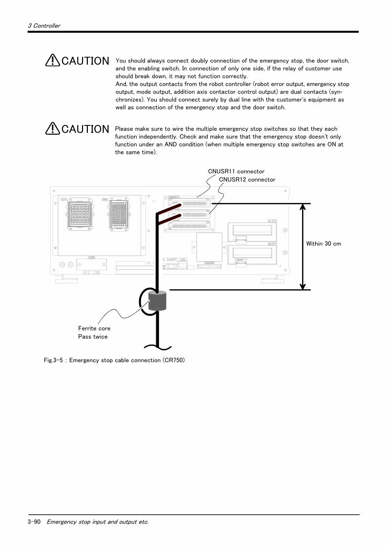
3-90 Emergency stop input and output etc.
3 Controller
You should always connect doubly connection of the emergency stop, the door switch, and the enabling switch. In connection of only one side, if the relay of customer use should break down, it may not function correctly.And, the output contacts from the robot controller (robot error output, emergency stop output, mode output, addition axis contactor control output) are dual contacts (syn-chronizes). You should connect surely by dual line with the customer's equipment as well as connection of the emergency stop and the door switch.
Please make sure to wire the multiple emergency stop switches so that they each function independently. Check and make sure that the emergency stop doesn't only function under an AND condition (when multiple emergency stop switches are ON at the same time).
Fig.3-5 : Emergency stop cable connection (CR750)
CAUTION
CAUTION
30cm以内
フェライトコア2回通し
CNUSR11コネクタ
CNUSR12コネクタ
CNUSR11 connector
Within 30 cm
Ferrite core
Pass twice
CNUSR12 connector
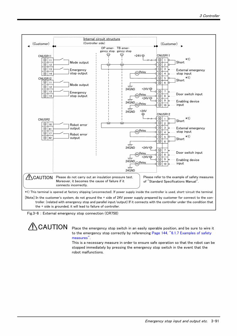
3 Controller
Emergency stop input and output etc. 3-91
Fig.3-6 : External emergency stop connection (CR750)
Place the emergency stop switch in an easily operable position, and be sure to wire it to the emergency stop correctly by referencing Page 144, "6.1.7 Examples of safety measures". This is a necessary measure in order to ensure safe operation so that the robot can be stopped immediately by pressing the emergency stop switch in the event that the robot malfunctions.
CNUSR11
CNUSR2
内部回路構成(お客様配線側) (コントローラ側)
警告 絶縁耐圧試験は行なわないでください。また誤って接続した場合は故障の原因となります。
10
9
8
7
3
4
2
CNUSR11+24V
Relay
+24V
24GND
24GND
24GND
RA+24V
RelayRA
RelayRA
外部非常停止入力
ドアスイッチ入力
イネーブリングデバイス入力
TB非常停止
+24V
Relay
+24V
24GND
24GND
24GND
RA+24V
RelayRA
RelayRA
14
13
12
11
17
41
16
モード出力
非常停止出力
ロボットエラー出力外部非常停止入力
ドアスイッチ入力
イネーブリングデバイス入力
(お客様配線側)
短絡
短絡
短絡
短絡
モード出力
非常停止出力
ロボットエラー出力
CNUSR12
14
13
12
11
1
5
6
10
9
8
7
3
4
2
1
5
6
CNUSR12
OP非常停止
Please refer to the example of safety measures of "Standard Specifications Manual".
内部回路構成( コ ン ト ローラ側 )
Please do not carry out an insulation pressure test.Moreover, it becomes the cause of failure if it connects incorrectly.
CAUTION
Internal circuit structure(Controller side)(Customer) (Customer)
Mode output
Mode output
Robot error output
Robot error output
Emergency stop output
Emergency stop output
Short
External emergency stop input
Short
Door switch input
Enabling device input
Short
External emergency stop input
Short
Door switch input
Enabling device input
TB emer-gency stop
OP emer-gency stop
*1) This terminal is opened at factory shipping (unconnected). If power supply inside the controller is used, short-circuit the terminal.
*1)
*1)
*1)
*1)
[Note] In the customer's system, do not ground the + side of 24V power supply prepared by customer for connect to the con-troller. (related with emergency stop and parallel input/output) If it connects with the controller under the condition that the + side is grounded, it will lead to failure of controller.
CAUTION
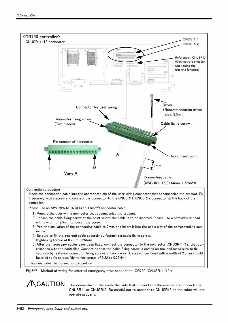
3-92 Emergency stop input and output etc.
3 Controller
Fig.3-7 : Method of wiring for external emergency stop connection (CR750 (CNUSR11/12))
The connector on the controller side that connects to the user wiring connector is CNUSR11 or CNUSR12. Be careful not to connect to CNUSR13 as the robot will not operate properly.
<CR750 controller>CNUSR11/12 connector
CNUSR11
CNUSR12
Driver
*Recommendation driver size: 2.5mm.
Cable fixing screw
Cable insert point
7mm
A
View A
161
Connector fixing screw
(Two places)
Pin number of connector
Connecting cable
(AWG #26-16 (0.14mm-1.5mm2))
Connection procedureInsert the connection cable into the appropriate pin of the user wiring connector that accompanies the product. Fix it securely with a screw and connect the connector to the CNUSR11/CNUSR12 connector at the back of the controller.
Please use an AWG #26 to 16 (0.14 to 1.5mm2) connector cable.
1) Prepare the user wiring connector that accompanies the product.2) Loosen the cable fixing screw at the point where the cable is to be inserted. Please use a screwdriver head
with a width of 2.5mm to loosen the screw.3) Peel the insulation of the connecting cable to 7mm, and insert it into the cable slot of the corresponding con-
nector.4) Be sure to fix the inserted cable securely by fastening a cable fixing screw.
(tightening torque of 0.22 to 0.25Nm)5) After the necessary cables save been fixed, connect the connector to the connector (CNUSR11/12) that cor-
responds with the controller. Connect so that the cable fixing screw is comes on top, and make sure to fix securely by fastening connector fixing screws in two places. A screwdriver head with a width of 2.5mm should be used to fix screws (tightening torque of 0.22 to 0.25Nm).
This concludes the connection procedure.
Connector for user wiring
Reference: CNUSR13 (Connect the encoder, when using the tracking function)
CAUTION
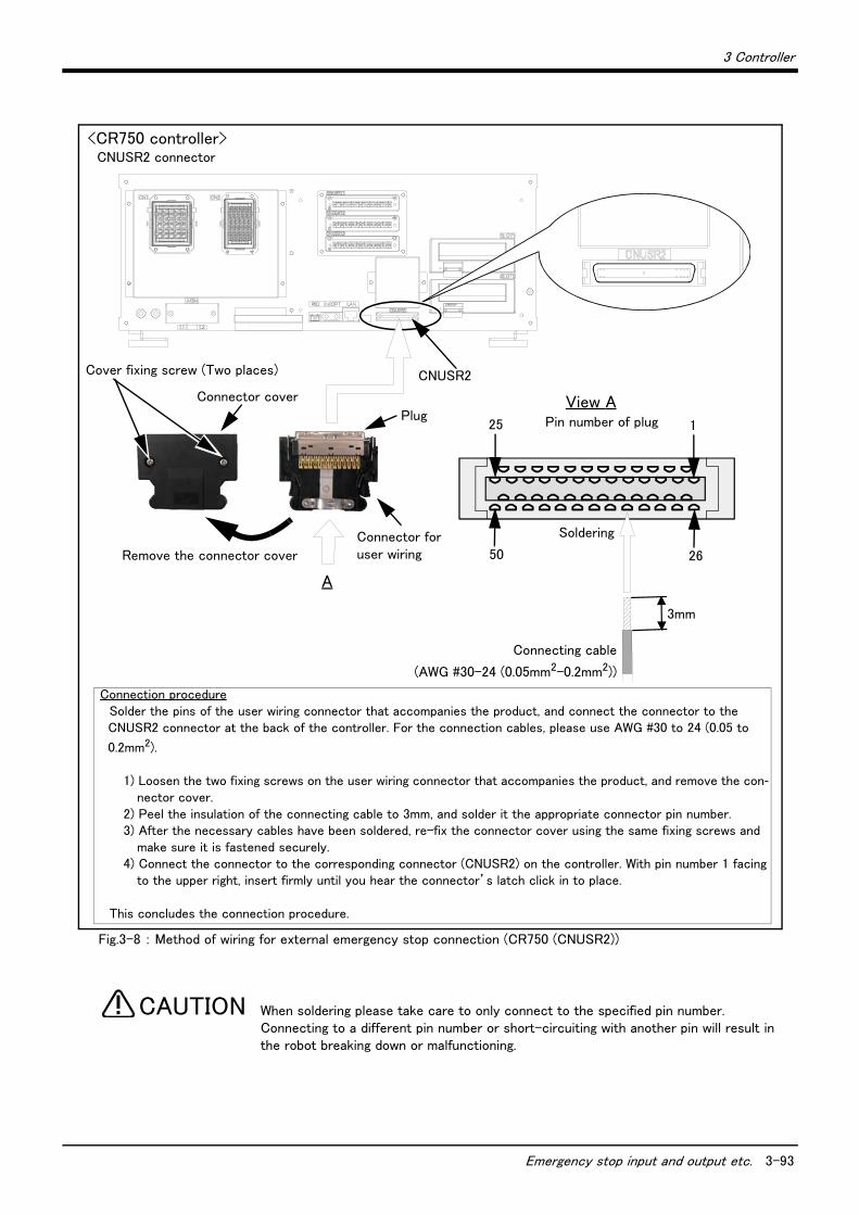
3 Controller
Emergency stop input and output etc. 3-93
Fig.3-8 : Method of wiring for external emergency stop connection (CR750 (CNUSR2))
When soldering please take care to only connect to the specified pin number. Connecting to a different pin number or short-circuiting with another pin will result in the robot breaking down or malfunctioning.
<CR750 controller>CNUSR2 connector
CNUSR2
3mm
A
View APlug
Connector cover
Connecting cable
(AWG #30-24 (0.05mm2-0.2mm2))
Connection procedureSolder the pins of the user wiring connector that accompanies the product, and connect the connector to the CNUSR2 connector at the back of the controller. For the connection cables, please use AWG #30 to 24 (0.05 to
0.2mm2).
1) Loosen the two fixing screws on the user wiring connector that accompanies the product, and remove the con-nector cover.
2) Peel the insulation of the connecting cable to 3mm, and solder it the appropriate connector pin number.3) After the necessary cables have been soldered, re-fix the connector cover using the same fixing screws and
make sure it is fastened securely.4) Connect the connector to the corresponding connector (CNUSR2) on the controller. With pin number 1 facing
to the upper right, insert firmly until you hear the connector’s latch click in to place.
This concludes the connection procedure.
Cover fixing screw (Two places)
Remove the connector cover
Pin number of plug25 1
50 26
SolderingConnector for user wiring
CAUTION
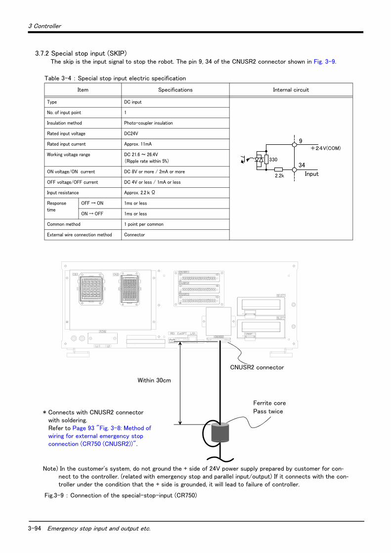
3-94 Emergency stop input and output etc.
3 Controller
3.7.2 Special stop input (SKIP)The skip is the input signal to stop the robot. The pin 9, 34 of the CNUSR2 connector shown in Fig. 3-9.
Table 3-4 : Special stop input electric specification
Fig.3-9 : Connection of the special-stop-input (CR750)
Item Specifications Internal circuit
Type DC input
No. of input point 1
Insulation method Photo-coupler insulation
Rated input voltage DC24V
Rated input current Approx. 11mA
Working voltage range DC 21.6 ~ 26.4V
(Ripple rate within 5%)
ON voltage/ON current DC 8V or more / 2mA or more
OFF voltage/OFF current DC 4V or less / 1mA or less
Input resistance Approx. 2.2 k Ω
Response
time
OFF → ON 1ms or less
ON → OFF 1ms or less
Common method 1 point per common
External wire connection method Connector
330
2.2k 入力
+24V(COM)
1A
1B
Input
9
34
CNUSR2
フェライトコア2回通し
30cm以内
* Connects with CNUSR2 connector with soldering. Refer to Page 93 "Fig. 3-8: Method of wiring for external emergency stop connection (CR750 (CNUSR2))".
Within 30cm
CNUSR2 connector
Ferrite core
Pass twice
Note) In the customer's system, do not ground the + side of 24V power supply prepared by customer for con-nect to the controller. (related with emergency stop and parallel input/output) If it connects with the con-troller under the condition that the + side is grounded, it will lead to failure of controller.

3 Controller
Emergency stop input and output etc. 3-95
3.7.3 Door switch functionThis function retrieves the status of the switch installed on the door of the safety fence, etc., and stops the robot when the door is opened. This differs from an emergency stop in that the servo turns OFF when the door is opened and an error does not occur. Follow the wiring example shown in Page 91 "Fig. 3-6: External emergency stop connection (CR750)" and Page 144, "6.1.7 Examples of safety measures". Those figure explains the wire is contact closes when the door is closed. Details of this function according to the robot status are shown below.
*During automatic operation ..............When the door is opened, the servo turns OFF and the robot stops. An error occurs.The process of the restoration: Close the door, reset the alarm, turn on the servo, and restart
*During teaching........................................ Even when the door is opened, the servo can be turned ON and the robot moved using the teaching pendant.
Fig.3-10 : Door switch function
3.7.4 Enabling device functionWhen the abnormalities occur in teaching operations etc., the robot's servo power can be immediately cut only by
switch operation of the enabling device*1) (servo-off), and the safety increases. To use the robot safely, please be sure to connect the enabling device.
(1) When door is openingPlease do teaching by two-person operations. One person has T/B, the other has enabling device. Turn on the servo power, in the condition that both of switches are pushed. (Enable switch of T/B and enabling device) Then the jog operation will be available. You can off the servo power only by releasing the switch of the enabling device.And, care that the servo-on and releasing the brake cannot be done in the condition that the switch of the enabling device is released.
(2) When door is closingYou can turn on the servo power by operation of only T/B. In this case perform jog operation outside the safeguard sure.
*1) Recommendation products: HE1G-L20MB (IDEC)
Safeguard
Turns OFF the servo
STOP!!
Open
TEACH
AUTO (Ext.)
AUTO (Op.)
Open
TEACH
AUTO (Ext.)
AUTO (Op.)
The servo can be turned ON/Off by turning the enable switch ON/OFF.
Safeguard
Teaching pendant
Robot arm (Example)
Robot arm (Example)
MODEMANUAL AUTOMATIC
① Auto executing
② Teaching
MODEMANUAL AUTOMATIC
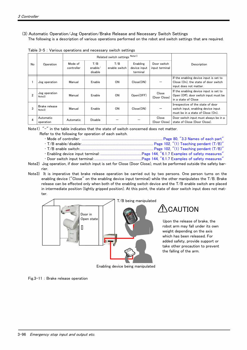
3-96 Emergency stop input and output etc.
3 Controller
(3) Automatic Operation/Jog Operation/Brake Release and Necessary Switch SettingsThe following is a description of various operations performed on the robot and switch settings that are required.
Table 3-5 : Various operations and necessary switch settings
Fig.3-11 : Brake release operation
No Operation
Related switch settings Note1)
Note1) "-" in the table indicates that the state of switch concerned does not matter.Refer to the following for operation of each switch.
・ Mode of controller: ................................................................................................ Page 80, "3.3 Names of each part"・ T/B enable/disable:..................................................................................... Page 102, "(1) Teaching pendant (T/B)"・ T/B enable switch:....................................................................................... Page 102, "(1) Teaching pendant (T/B)"・ Enabling device input terminal: .................................................Page 144, "6.1.7 Examples of safety measures"・ Door switch input terminal: ........................................................Page 144, "6.1.7 Examples of safety measures"
DescriptionMode of
controller
T/B
enable/
disable
T/B
enable switch
Enabling
device input
terminal
Door switch
input terminal
1 Jog operation Manual Enable ON Close(ON) -
If the enabling device input is set to
Close (On), the state of door switch
input does not matter.
2Jog operation Note2)
Note2) Jog operation, if door switch input is set for Close (Door Close), must be performed outside the safety bar-rier.
Manual Enable ON Open(OFF)Close
(Door Close)
If the enabling device input is set to
Open (Off), door switch input must be
in a state of Close
3Brake release Note3)
Note3) It is imperative that brake release operation be carried out by two persons. One person turns on theenabling device ("Close" on the enabling device input terminal) while the other manipulates the T/B. Brakerelease can be effected only when both of the enabling switch device and the T/B enable switch are placedin intermediate position (lightly gripped position). At this point, the state of door switch input does not mat-ter.
Manual Enable ON Close(ON) -
Irrespective of the state of door
switch input, enabling device input
must be in a state of Close (On).
4Automatic
operationAutomatic Disable - -
Close
(Door Close)
Door switch input must always be in a
state of Close (Door Close).
Door in Open state
Upon the release of brake, the robot arm may fall under its own weight depending on the axis which has been released. For added safety, provide support or take other precaution to prevent the falling of the arm.
CAUTION
T/B being manipulated
Enabling device being manipulated
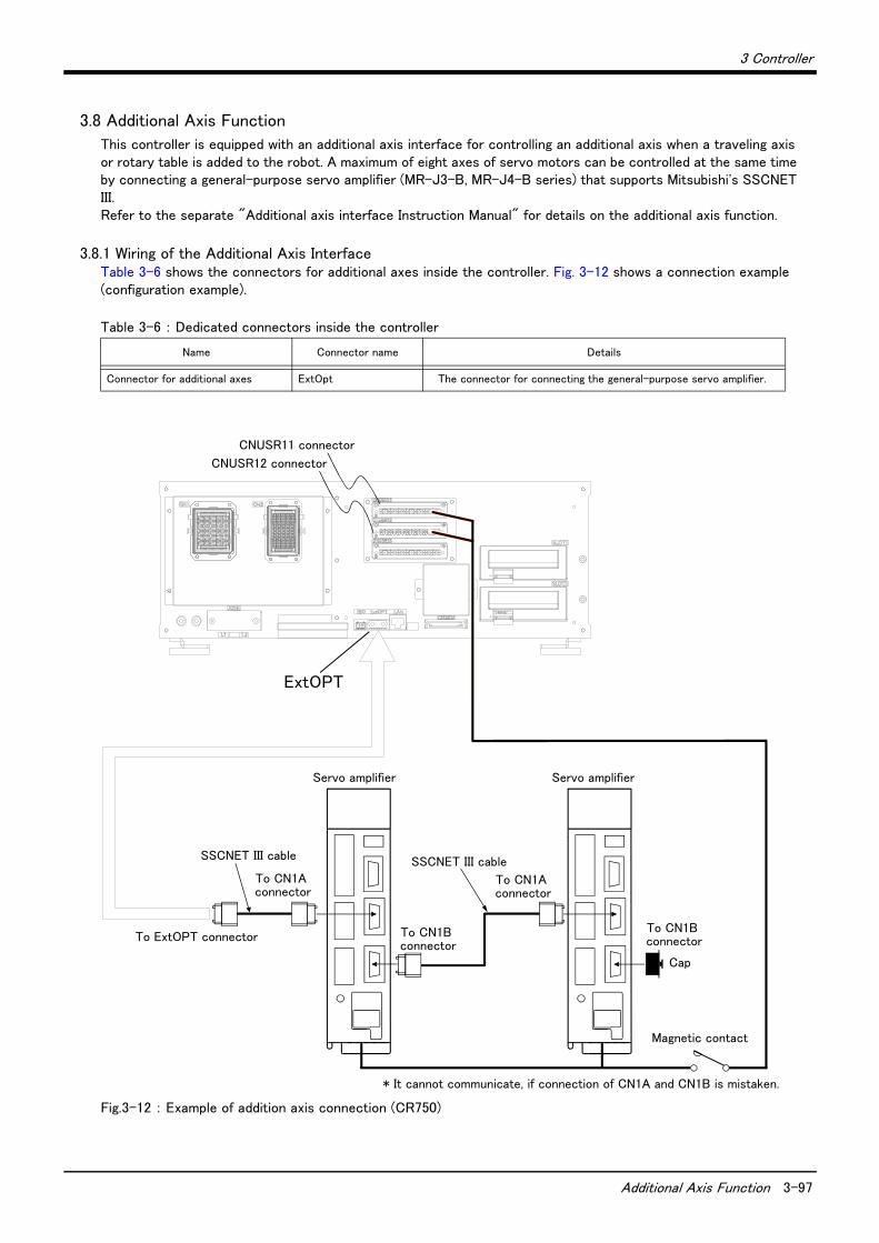
3 Controller
Additional Axis Function 3-97
3.8 Additional Axis Function
This controller is equipped with an additional axis interface for controlling an additional axis when a traveling axis or rotary table is added to the robot. A maximum of eight axes of servo motors can be controlled at the same time by connecting a general-purpose servo amplifier (MR-J3-B, MR-J4-B series) that supports Mitsubishi's SSCNET III. Refer to the separate "Additional axis interface Instruction Manual" for details on the additional axis function.
3.8.1 Wiring of the Additional Axis InterfaceTable 3-6 shows the connectors for additional axes inside the controller. Fig. 3-12 shows a connection example (configuration example).
Table 3-6 : Dedicated connectors inside the controller
Fig.3-12 : Example of addition axis connection (CR750)
Name Connector name Details
Connector for additional axes ExtOpt The connector for connecting the general-purpose servo amplifier.
ExtOPTコネクタへ
サーボアンプ
※CN1A、CN1Bの接続を間違えると、通信できません。
キャップ
サーボアンプ
CN1Aコネクタへ CN1Aコネクタへ
CN1Bコネクタへ
SSCNETⅢケーブルSSCNETⅢケーブル
CN1Bコネクタへ
電磁接触器
ExtOPT
CNUSR11コネクタ
CNUSR12コネクタ
Servo amplifier
SSCNET III cable
Cap
Magnetic contact
* It cannot communicate, if connection of CN1A and CN1B is mistaken.
To CN1A connector
CNUSR11 connector
CNUSR12 connector
Servo amplifier
SSCNET III cable
To CN1B connector
To CN1A connector
To ExtOPT connectorTo CN1B connector

3-98 Additional Axis Function
3 Controller
(1) Example of the installation of the noise filter1) EMC filter (recommended)
Please install the recommendation filter shown below according to the example of connection.
Fig.3-13 : Example of EMC noise filter installation
1)
2)
Note1) For 1-phase 200V to 230VAC power supply, connect the power supply to L1, L2 and leave L3 open. There is no L3 for 1-phase 100 to 120 VAC power supply.
Note2) The example is when a surge protector is connected.

3 Controller
Additional Axis Function 3-99
2) Line noise filter
This filter is effective in suppressing noises radiated from the power supply side and output side of the
servo amplifier and also in suppressing high-frequency leakage current (zero-phase current) especially
within 0.5MHz to 5MHz band.
Fig.3-14 : Example of noise filter installation
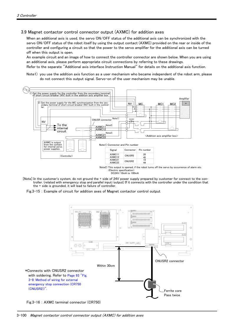
3-100 Magnet contactor control connector output (AXMC) for addition axes
3 Controller
3.9 Magnet contactor control connector output (AXMC) for addition axes
When an additional axis is used, the servo ON/OFF status of the additional axis can be synchronized with the servo ON/OFF status of the robot itself by using the output contact (AXMC) provided on the rear or inside of the controller and configuring a circuit so that the power to the servo amplifier for the additional axis can be turned off when this output is open. An example circuit and an image of how to connect the controller connector are shown below. When you are using an additional axis, please perform appropriate circuit connections by referring to these drawings.
Refer to the separate "Additional axis interface Instruction Manual" for details on the additional axis function.
Note1) you use the addition axis function as a user mechanism who became independent of the robot arm, pleasedo not connect this output signal. Servo-on of the user mechanism may be unable.
Fig.3-15 : Example of circuit for addition axes of Magnet contactor control output
Fig.3-16 : AXMC terminal connector (CR750)
MC2NV MC MC1
内部回路へ
<コントローラ>
内部サーボ電源用コンタクタ接点より
AXMC出力
<走行軸(付加軸)アンプボックス>
NV
2)コントローラ内蔵漏電遮断器(NV)の2次側より、MC同期用電源を取り出す。
AXMC21注2)
1)付加軸アンプボックス内蔵漏電遮断器(NV)の2次側より、コントローラ電源を取り出す。
AXMC11
注1)
88
CNUSRコネクタ
アンプ
DC24V
AXMC12
AXMC22
注2)
注1)コネクタとピン番号を以下に示します。
AXMC11AXMC12AXMC21AXMC22
注2)ロボットがアラームの発生などでサーボOFFしたとき、本出力(接点)が開放します。<接点容量>DC24V/10mA~100mA
信号名 ピン番号コネクタ
CNUSR2451944
20
CNUSR2
1) Get the power supply for the controller from the secondary terminal of short circuit breaker (NV) built in the addition axis amplifier box.
2) Get the power supply for the MC synchronization from the sec-ondary terminal of short circuit breaker (NV) built in the control-ler.
To the internal circuit
AXMC is output from the contact for internal servo power supplies.
<Controller>
CNUSR connectorNote1)
Note2)
Note2)
Amplifier
<Addition axis amplifier box><Addition axis amplifier box>
Signal Connector Pin number
Note1) Connector and Pin number
Note2) This output is opened, if the robot turns off the servo by occurrence of alarm etc.<Electric specification>
DC24V/10mA to 100mA
[Note] In the customer's system, do not ground the + side of 24V power supply prepared by customer for connect to the con-troller. (related with emergency stop and parallel input/output) If it connects with the controller under the condition that the + side is grounded, it will lead to failure of controller.
30cm以内
フェライトコア2回通し
CNUSR2コネクタ
*Connects with CNUSR2 connector with soldering. Refer to Page 93 "Fig.
3-8: Method of wiring for external emergency stop connection (CR750
(CNUSR2))".
Within 30cm
Ferrite corePass twice
CNUSR2 connector

3 Controller
3-101
3.10 Options
■ What are options?There are a variety of options for the robot designed to make the setting up process easier for user needs.
User installation is required for the options. Options come in two types: "set options" and "single options".
1. Set options......................................A combination of single options and parts that together, form a set for servingsome purpose.
2. Single options.................................That are configured from the fewest number of required units of a part.Please choose user's purpose additionally.
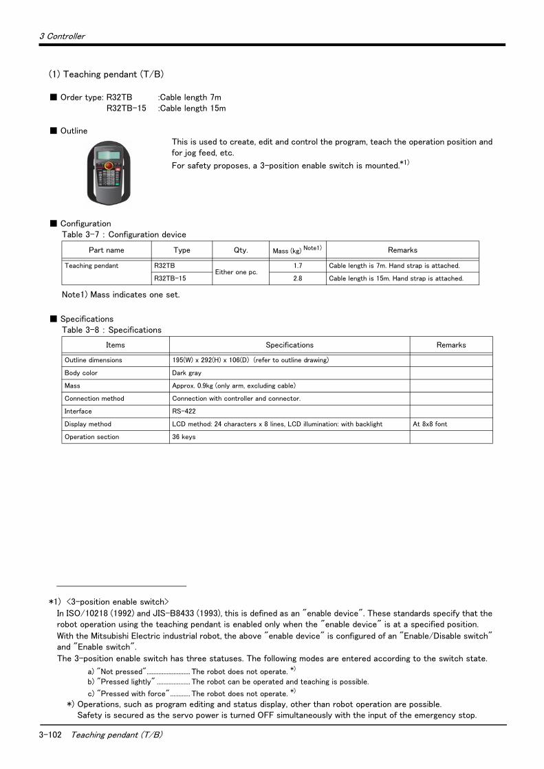
3-102 Teaching pendant (T/B)
3 Controller
(1) Teaching pendant (T/B)
■ Order type: R32TB :Cable length 7mR32TB-15 :Cable length 15m
■ OutlineThis is used to create, edit and control the program, teach the operation position and for jog feed, etc.
For safety proposes, a 3-position enable switch is mounted.*1)
■ ConfigurationTable 3-7 : Configuration device
■ SpecificationsTable 3-8 : Specifications
*1) <3-position enable switch>
In ISO/10218 (1992) and JIS-B8433 (1993), this is defined as an "enable device". These standards specify that the robot operation using the teaching pendant is enabled only when the "enable device" is at a specified position.
With the Mitsubishi Electric industrial robot, the above "enable device" is configured of an "Enable/Disable switch" and "Enable switch".
The 3-position enable switch has three statuses. The following modes are entered according to the switch state.
a) "Not pressed".......................... The robot does not operate. *)
b) "Pressed lightly" .................... The robot can be operated and teaching is possible.
c) "Pressed with force"............ The robot does not operate. *)
*) Operations, such as program editing and status display, other than robot operation are possible.Safety is secured as the servo power is turned OFF simultaneously with the input of the emergency stop.
Part name Type Qty. Mass (kg) Note1)
Note1) Mass indicates one set.
Remarks
Teaching pendant R32TBEither one pc.
1.7 Cable length is 7m. Hand strap is attached.
R32TB-15 2.8 Cable length is 15m. Hand strap is attached.
Items Specifications Remarks
Outline dimensions 195(W) x 292(H) x 106(D) (refer to outline drawing)
Body color Dark gray
Mass Approx. 0.9kg (only arm, excluding cable)
Connection method Connection with controller and connector.
Interface RS-422
Display method LCD method: 24 characters x 8 lines, LCD illumination: with backlight At 8x8 font
Operation section 36 keys

3 Controller
Teaching pendant (T/B) 3-103
Fig.3-17 : Outside dimensions of teaching pendant
■ Installation methodThe teaching pendant is connected to the T/B connector on the front of the controller.
Enable/Disable switch
Emergency stop
Enable switch
Operetion key
Body
Cable (with connector)
<Back>
<Bottom>
63.5
<Front>
LCD
291.9
195.2
133
<side>
105.5
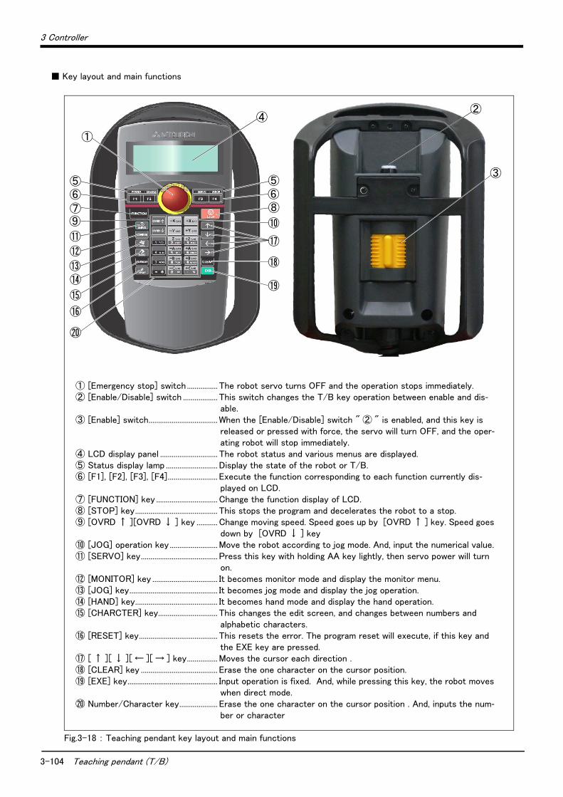
3-104 Teaching pendant (T/B)
3 Controller
■ Key layout and main functions
Fig.3-18 : Teaching pendant key layout and main functions
⑪
⑭⑬
⑫
⑨
⑤⑥⑦
⑮
⑯
⑳
⑤⑥⑧
⑱
⑲
⑩
⑰
①
④
③
②
① [Emergency stop] switch ................ The robot servo turns OFF and the operation stops immediately.② [Enable/Disable] switch .................. This switch changes the T/B key operation between enable and dis-
able.③ [Enable] switch.................................... When the [Enable/Disable] switch " ② " is enabled, and this key is
released or pressed with force, the servo will turn OFF, and the oper-ating robot will stop immediately.
④ LCD display panel .............................. The robot status and various menus are displayed.⑤ Status display lamp ........................... Display the state of the robot or T/B.⑥ [F1], [F2], [F3], [F4].......................... Execute the function corresponding to each function currently dis-
played on LCD. ⑦ [FUNCTION] key ................................ Change the function display of LCD. ⑧ [STOP] key........................................... This stops the program and decelerates the robot to a stop.⑨ [OVRD ↑ ][OVRD ↓ ] key ........... Change moving speed. Speed goes up by [OVRD ↑ ] key. Speed goes
down by [OVRD ↓ ] key⑩ [JOG] operation key......................... Move the robot according to jog mode. And, input the numerical value. ⑪ [SERVO] key........................................ Press this key with holding AA key lightly, then servo power will turn
on. ⑫ [MONITOR] key .................................. It becomes monitor mode and display the monitor menu.⑬ [JOG] key.............................................. It becomes jog mode and display the jog operation. ⑭ [HAND] key........................................... It becomes hand mode and display the hand operation.⑮ [CHARCTER] key............................... This changes the edit screen, and changes between numbers and
alphabetic characters.⑯ [RESET] key......................................... This resets the error. The program reset will execute, if this key and
the EXE key are pressed. ⑰ [ ↑ ][ ↓ ][ ← ][ → ] key................ Moves the cursor each direction .⑱ [CLEAR] key ........................................ Erase the one character on the cursor position.⑲ [EXE] key............................................... Input operation is fixed. And, while pressing this key, the robot moves
when direct mode.⑳ Number/Character key.................... Erase the one character on the cursor position . And, inputs the num-
ber or character

3 Controller
Parallel I/O interface 3-105
(2) Parallel I/O interface
■ Order type : ● 2D-TZ368 (Sink type)/2D-TZ378 (Source type)
■ Outline
This is used to expand the external inputs and outputs
・ The connecting cable with external equipment is not attached. Since we are preparing the external input-and-output cable (2D-CBL05 or 2D-CBL15) as the option, please use.
Notes)Although the combined use with the parallel input-and-output unit (2A-RZ361/2A-RZ371) of another option is also possible, please use the setup of the station number by the different number separately. The station number is automatically determined by the position of the option slot which installed this interface. (station number 0 to 2)
■ ConfigurationTable 3-9 : Configuration device
■ SpecificationsTable 3-10 : Electrical specifications of input circuits
Part name Type Qty. Mass (kg) Note1)
Note1) Mass indicates one set.
Remarks
Parallel I/O interface 2D-TZ368 Either
one pc.
0.4 Input/output 32 points/32 points2D-TZ368 is sink type. 2D-TZ378 is source type.
2D-TZ378
Item Specification Internal circuit
Type DC input <Sink type>
<Source type>
Number of input points 32
Insulation method Photo coupler insulation
Rated input voltage DC12V DC24V
Rated input current Approx. 3mA Approx.9mA
Working voltage range DC10.2 ~ 26.4V
(Ripple factor should be less than 5%)
ON voltage/ON current DC8V or more/2mA or more
OFF voltage/ OFF current DC4V or less/1mA or less
Input resistance Approx. 2.7kΩ
Response time OFF-ON 10ms or less(DC24V)
ON-OFF 10ms or less(DC24V)
Common method 32 points per common
External cable connection
method
Connector
Input
+24V/+12V(COM)
2.7K
820
2.7K
820
0V(COM)
Input
3-106 Parallel I/O interface
3 Controller
Table 3-11 : Electrical specifications for the output circuits
The protection fuse of the output circuit prevents the failure at the time of the load short circuit and incorrect connection. The load connected of the customer should be careful not to exceed maximum rating current. The internal transistor may be damaged if maximum rating current is exceeded.
■ Installation methodThe expansion parallel input/output interface is installed in the controller. Refer to separate "Instruction Manual/ Controller setup, basic operation, and maintenance" for details on the installing method.
If it installs in the option SLOT of the controller, the station number will be assigned automatically.
SLOT1: station number 0(0 to 31)
SLOT2: station number 1(32 to 63)
If it uses together with parallel input-and-output unit 2A-RZ361/2A-RZ371, please do not overlap with the station number of the parallel input-and-output interface.
Fig.3-19 : Parallel I/O interface installation position (CR750)
Item Specification Internal circuit
Type Transistor output <Sink type>
<Source type>
No. of output points 32
Insulation method Photo-coupler insulation
Rated load voltage DC12V/DC24V
Rated load voltage range DC10.2 ~ 30V (peak voltage DC30V)
Max. load current 0.1A/point (100%)
Leakage current at OFF Within 0.1mA
Max. voltage drop at ON DC0.9V(TYP.) Note1)
Note1) The maximum voltage drop value at signal ON. Refer to it for the equipment connected to the output circuit.
Respons
e time
OFF-ON 10ms or less(Resistance load) (hardware response time)
ON-OFF 10ms or less(Resistance load) (hardware response time)
Fuse rating Fuse 1.6A(one per common)
Replacement possible (max. 3)
Common method 16 points per common (common terminal: 2points)
External wire connection
method
Connector
External
power
supply
Voltage DC12/24V(DC10.2 ~ 30V)
Current 60mA(TYP.DC24V per common)(base drive current)
+24V/+12V
Output
0VFuse
+24V/+12V
0V
Fuse
Output
Caution
Caution
SLOT2
SLOT1
<CR750 controller>
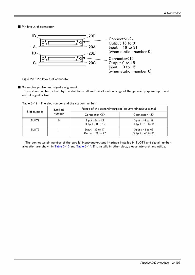
3 Controller
Parallel I/O interface 3-107
■ Pin layout of connector
Fig.3-20 : Pin layout of connector
■ Connector pin No. and signal assignmentThe station number is fixed by the slot to install and the allocation range of the general-purpose input-and-output signal is fixed.
Table 3-12 : The slot number and the station number
The connector pin number of the parallel input-and-output interface installed in SLOT1 and signal number allocation are shown in Table 3-13 and Table 3-14. If it installs in other slots, please interpret and utilize.
Slot numberStation number
Range of the general-purpose input-and-output signal
Connector <1> Connector <2>
SLOT1 0 Input : 0 to 15Output : 0 to 15
Input : 16 to 31Output : 16 to 31
SLOT2 1 Input : 32 to 47Output : 32 to 47
Input : 48 to 63Output : 48 to 63
1B
1A 20A
20B
1D
1C 20C
20D
Connector<2>Output 16 to 31Input 16 to 31(when station number 0)
Connector<1>Output 0 to 15Input 0 to 15(when station number 0)
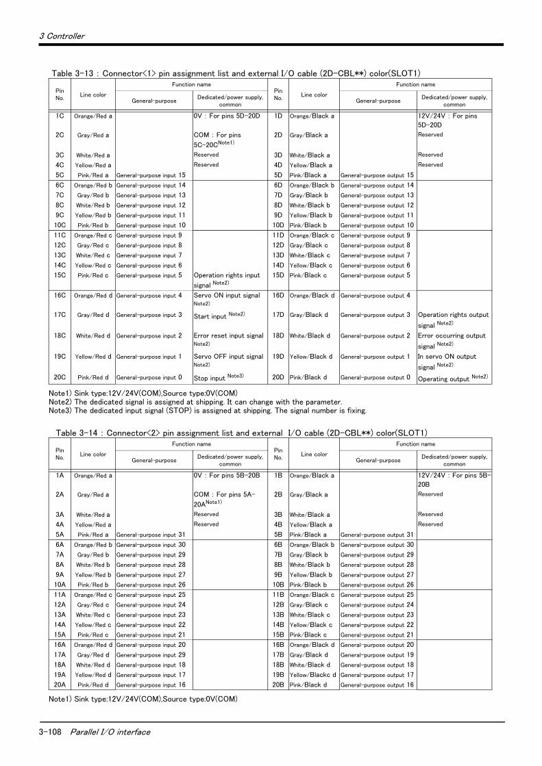
3-108 Parallel I/O interface
3 Controller
Table 3-13 : Connector<1> pin assignment list and external I/O cable (2D-CBL**) color(SLOT1)
Table 3-14 : Connector<2> pin assignment list and external I/O cable (2D-CBL**) color(SLOT1)
PinNo.
Line color
Function namePinNo.
Line color
Function name
General-purposeDedicated/power supply,
commonGeneral-purpose
Dedicated/power supply, common
1C Orange/Red a 0V : For pins 5D-20D 1D Orange/Black a 12V/24V : For pins
5D-20D
2C Gray/Red a COM : For pins
5C-20CNote1)
Note1) Sink type:12V/24V(COM),Source type:0V(COM)
2D Gray/Black a Reserved
3C White/Red a Reserved 3D White/Black a Reserved
4C Yellow/Red a Reserved 4D Yellow/Black a Reserved
5C Pink/Red a General-purpose input 15 5D Pink/Black a General-purpose output 15
6C Orange/Red b General-purpose input 14 6D Orange/Black b General-purpose output 14
7C Gray/Red b General-purpose input 13 7D Gray/Black b General-purpose output 13
8C White/Red b General-purpose input 12 8D White/Black b General-purpose output 12
9C Yellow/Red b General-purpose input 11 9D Yellow/Black b General-purpose output 11
10C Pink/Red b General-purpose input 10 10D Pink/Black b General-purpose output 10
11C Orange/Red c General-purpose input 9 11D Orange/Black c General-purpose output 9
12C Gray/Red c General-purpose input 8 12D Gray/Black c General-purpose output 8
13C White/Red c General-purpose input 7 13D White/Black c General-purpose output 7
14C Yellow/Red c General-purpose input 6 14D Yellow/Black c General-purpose output 6
15C Pink/Red c General-purpose input 5 Operation rights input
signal Note2)
Note2) The dedicated signal is assigned at shipping. It can change with the parameter.
15D Pink/Black c General-purpose output 5
16C Orange/Red d General-purpose input 4 Servo ON input signal Note2)
16D Orange/Black d General-purpose output 4
17C Gray/Red d General-purpose input 3 Start input Note2) 17D Gray/Black d General-purpose output 3 Operation rights output
signal Note2)
18C White/Red d General-purpose input 2 Error reset input signal Note2)
18D White/Black d General-purpose output 2 Error occurring output
signal Note2)
19C Yellow/Red d General-purpose input 1 Servo OFF input signal Note2)
19D Yellow/Black d General-purpose output 1 In servo ON output
signal Note2)
20C Pink/Red d General-purpose input 0 Stop input Note3)
Note3) The dedicated input signal (STOP) is assigned at shipping. The signal number is fixing.
20D Pink/Black d General-purpose output 0 Operating output Note2)
PinNo.
Line color
Function namePinNo.
Line color
Function name
General-purposeDedicated/power supply,
commonGeneral-purpose
Dedicated/power supply, common
1A Orange/Red a 0V : For pins 5B-20B 1B Orange/Black a 12V/24V : For pins 5B-
20B
2A Gray/Red a COM : For pins 5A-
20ANote1)
Note1) Sink type:12V/24V(COM),Source type:0V(COM)
2B Gray/Black a Reserved
3A White/Red a Reserved 3B White/Black a Reserved
4A Yellow/Red a Reserved 4B Yellow/Black a Reserved
5A Pink/Red a General-purpose input 31 5B Pink/Black a General-purpose output 31
6A Orange/Red b General-purpose input 30 6B Orange/Black b General-purpose output 30
7A Gray/Red b General-purpose input 29 7B Gray/Black b General-purpose output 29
8A White/Red b General-purpose input 28 8B White/Black b General-purpose output 28
9A Yellow/Red b General-purpose input 27 9B Yellow/Black b General-purpose output 27
10A Pink/Red b General-purpose input 26 10B Pink/Black b General-purpose output 26
11A Orange/Red c General-purpose input 25 11B Orange/Black c General-purpose output 25
12A Gray/Red c General-purpose input 24 12B Gray/Black c General-purpose output 24
13A White/Red c General-purpose input 23 13B White/Black c General-purpose output 23
14A Yellow/Red c General-purpose input 22 14B Yellow/Black c General-purpose output 22
15A Pink/Red c General-purpose input 21 15B Pink/Black c General-purpose output 21
16A Orange/Red d General-purpose input 20 16B Orange/Black d General-purpose output 20
17A Gray/Red d General-purpose input 29 17B Gray/Black d General-purpose output 19
18A White/Red d General-purpose input 18 18B White/Black d General-purpose output 18
19A Yellow/Red d General-purpose input 17 19B Yellow/Blackc d General-purpose output 17
20A Pink/Red d General-purpose input 16 20B Pink/Black d General-purpose output 16

3 Controller
Parallel I/O interface 3-109
<Reference> The example of connection with our PLC
Table 3-15 : Connection with a Mitsubishi PLC (Example of sink type)
Table 3-16 : Connection with a Mitsubishi PLC (Example of source type)
60mA (24/12V)
Output
Fuse(0V)
(COM)
QX41(Mitsubishi programmablecontroller)
QY41P(Mitsubishi programmablecontroller)
+24V
COM
X
Y
24V
……
Input
Parallel I/O interface (Output)
(Input)
3.3K
Output
Input
Externalpower supply
24G(24GND)COM
Externalpower supply
24V…
…
<Sink>
*The input/output circuit external power supply (24 VDC) must be prepared by the customer.
Note) In the customer's system, do not ground the + side of 24V power supply prepared by customer for connect to the controller. (related with emergency stop and parallel input/output) If it connects with the controller under the condition that the + side is grounded, it will lead to failure of controller.
<Source>
60mA (24/12V)
Output
Output
Fuse
(0V)
(COM)
QX41
24G(24GND)
+24V
COM
External power supply
X
Y
24V
24V
(Output)
(Input)
3.3K
External power supply
Input
Input
……
……
QY81P
Parallel I/O interface
(Output) (Mitsubishi programmablecontroller)
(Mitsubishi programmablecontroller)
*The input/output circuit external power supply (24 VDC) must be prepared by the customer.
Note) In the customer's system, do not ground the + side of 24V power supply prepared by customer for connect to the controller. (related with emergency stop and parallel input/output) If it connects with the controller under the condition that the + side is grounded, it will lead to failure of controller.
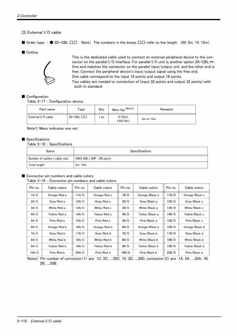
3-110 External I/O cable
3 Controller
(3) External I/O cable
■ Order type : ● 2D-CBL □□ Note) The numbers in the boxes □□ refer to the length. (05: 5m, 15: 15m)
■ OutlineThis is the dedicated cable used to connect an external peripheral device to the con-nector on the parallel I/O interface. For parallel I/O unit is another option 2A-CBL.**. One end matches the connector on the parallel input/output unit, and the other end is free. Connect the peripheral device's input/output signal using the free end.
One cable correspond to the input 16 points and output 16 points.
Two cables are needed to connection of (input 32 points and output 32 points) with built-in standard.
■ ConfigurationTable 3-17 : Configuration device
■ SpecificationsTable 3-18 : Specifications
■ Connector pin numbers and cable colorsTable 3-19 : Connector pin numbers and cable colors
Notes) Pin number of connector<1> are 1C, 2C, ....20C, 1D, 2D, ....20D, connector<2> are 1A, 2A, ....20A, 1B, 2B, ....20B.
Part name Type Qty. Mass (kg) Note1)
Note1) Mass indicates one set.
Remarks
External I/O cable 2D-CBL □□ 1 pc. 0.7(5m)
1.84(15m)5m or 15m
Items Specifications
Number of cables x cable size AWG #28 x 20P (40 pairs)
Total length 5m, 15m
Pin no. Cable colors Pin no. Cable colors Pin no. Cable colors Pin no. Cable colors
1A/C Orange/Red a 11A/C Orange/Red c 1B/D Orange/Black a 11B/D Orange/Black c
2A/C Gray/Red a 12A/C Gray/Red c 2B/D Gray/Black a 12B/D Gray/Black c
3A/C White/Red a 13A/C White/Red c 3B/D White/Black a 13B/D White/Black c
4A/C Yellow/Red a 14A/C Yellow/Red c 4B/D Yellow/Black a 14B/D Yellow/Black c
5A/C Pink/Red a 15A/C Pink/Red c 5B/D Pink/Black a 15B/D Pink/Black c
6A/C Orange/Red b 16A/C Orange/Red d 6B/D Orange/Black b 16B/D Orange/Black d
7A/C Gray/Red b 17A/C Gray/Red d 7B/D Gray/Black b 17B/D Gray/Black d
8A/C White/Red b 18A/C White/Red d 8B/D White/Black b 18B/D White/Black d
9A/C Yellow/Red b 19A/C Yellow/Red d 9B/D Yellow/Black b 19B/D Yellow/Black d
10A/C Pink/Red b 20A/C Pink/Red d 10B/D Pink/Black b 20B/D Pink/Black d

3 Controller
External I/O cable 3-111
■ Connections and outside dimensionsThe sheath of each signal cable (40 lines) is color indicated and marked with dots. Refer to the cable color speci-fications in "Table 3-30: Connector pin numbers and cable colors" when making the connections.
Fig.3-21 : Connections and outside dimensions
(Eg.) Pin number: color indication
1 : Orange / Red / A
Type of dot mark (see figure below)
Color of dot mark
Color of sheath
Line colortype
a type
Pattern of the print mark
One dot
Two dots
Three dots
Four dots
b type
c type
d type
1A/C 1B/D
20A/C 20B/D
or
Plug (Fujitsu Ltd) Connector : FCN-361J040-AU
Cover : FCN-360C040-B
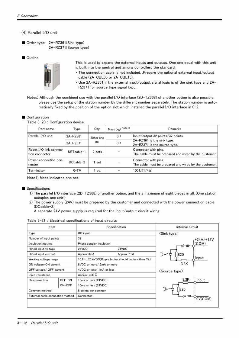
3-112 Parallel I/O unit
3 Controller
(4) Parallel I/O unit
■ Order type: 2A-RZ361(Sink type)2A-RZ371(Source type)
■ OutlineThis is used to expand the external inputs and outputs. One one equal with this unit is built into the control unit among controllers the standard.
・ The connection cable is not included. .Prepare the optional external input/output cable (2A-CBL05 or 2A-CBL15).
・ Use 2A-RZ361 if the external input/output signal logic is of the sink type and 2A-RZ371 for source type signal logic.
Notes) Although the combined use with the parallel I/O interface (2D-TZ368) of another option is also possible, please use the setup of the station number by the different number separately. The station number is auto-matically fixed by the position of the option slot which installed the parallel I/O interface in 0-2.
■ ConfigurationTable 3-20 : Configuration device
■ Specifications1) The parallel I/O interface (2D-TZ368) of another option, and the a maximum of eight pieces in all. (One station
occupies one unit.)2) The power supply (24V) must be prepared by the customer and connected with the power connection cable
(DCcable-2)A separate 24V power supply is required for the input/output circuit wiring.
Table 3-21 : Electrical specifications of input circuits
Part name Type Qty. Mass (kg) Note1)
Note1) Mass indicates one set.
Remarks
Parallel I/O unit 2A-RZ361 Either one
pc.
0.7 Input/output 32 points/32 points2A-RZ361 is the sink type.2A-RZ371 is the source type.2A-RZ371 0.7
Robot I/O link connec-tion connector
NETcable-1 2 sets -Connector with pins.The cable must be prepared and wired by the customer.
Power connection con-nector
DCcable-2 1 set -Connector with pins.The cable must be prepared and wired by the customer.
Terminator R-TM 1 pc. - 100Ω(1/4W)
Item Specification Internal circuit
Type DC input <Sink type>
<Source type>
Number of input points 32
Insulation method Photo coupler insulation
Rated input voltage 24VDC 24VDC
Rated input current Approx 3mA Approx 7mA
Working voltage range 10.2 to 26.4VDC(Ripple factor should be less than 5%.)
ON voltage/ON current 8VDC or more/ 2mA or more
OFF voltage/ OFF current 4VDC or less/ 1mA or less
Input resistance Approx. 3.3kΩ
Response time OFF-ON 10ms or less (24VDC)
ON-OFF 10ms or less (24VDC)
Common method 8 points per common
External cable connection method Connector
入力
+24V/+12V(COM)
3.3K
820Input
3.3K
820
0V(COM)
入力Input
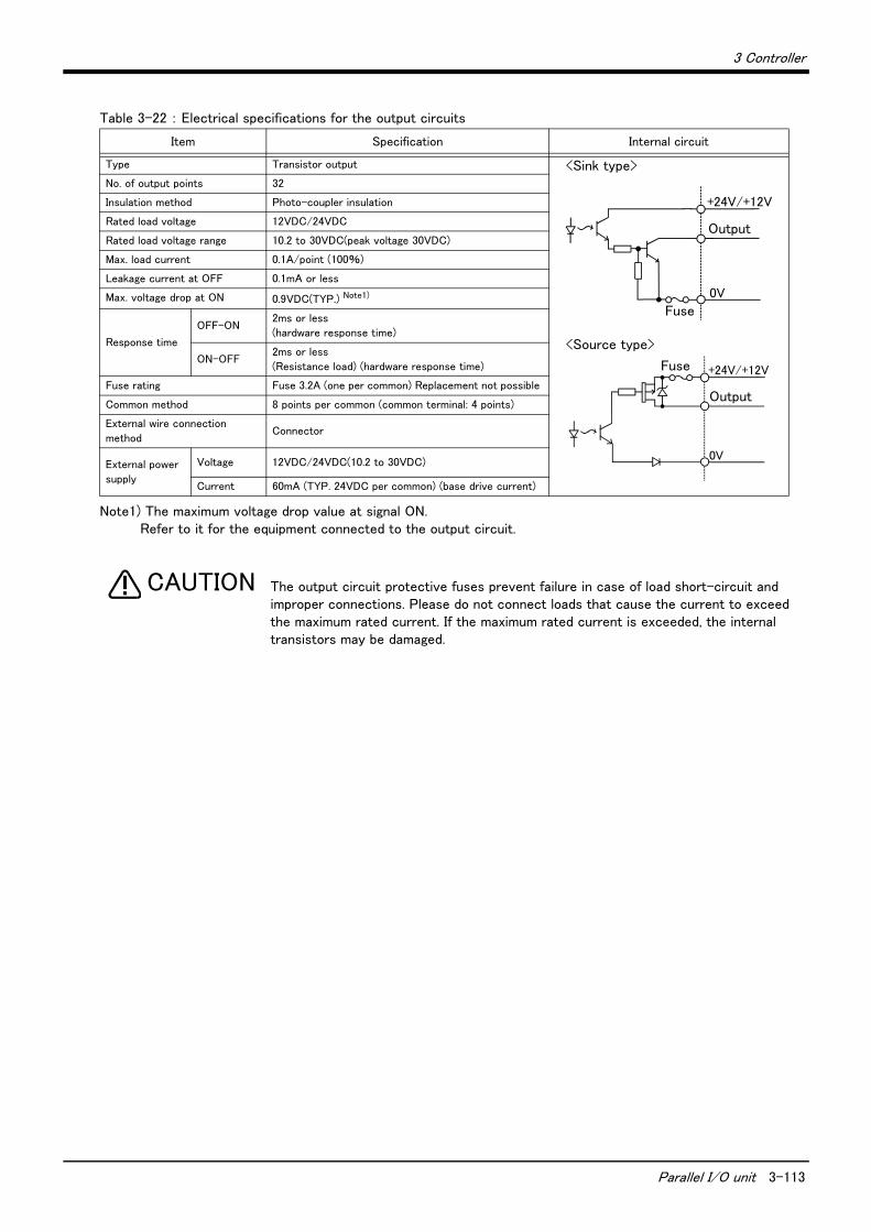
3 Controller
Parallel I/O unit 3-113
Table 3-22 : Electrical specifications for the output circuits
The output circuit protective fuses prevent failure in case of load short-circuit and improper connections. Please do not connect loads that cause the current to exceed the maximum rated current. If the maximum rated current is exceeded, the internal transistors may be damaged.
Item Specification Internal circuit
Type Transistor output <Sink type>
<Source type>
No. of output points 32
Insulation method Photo-coupler insulation
Rated load voltage 12VDC/24VDC
Rated load voltage range 10.2 to 30VDC(peak voltage 30VDC)
Max. load current 0.1A/point (100%)
Leakage current at OFF 0.1mA or less
Max. voltage drop at ON 0.9VDC(TYP.) Note1)
Note1) The maximum voltage drop value at signal ON. Refer to it for the equipment connected to the output circuit.
Response time
OFF-ON 2ms or less
(hardware response time)
ON-OFF 2ms or less
(Resistance load) (hardware response time)
Fuse rating Fuse 3.2A (one per common) Replacement not possible
Common method 8 points per common (common terminal: 4 points)
External wire connection
method Connector
External power
supply
Voltage 12VDC/24VDC(10.2 to 30VDC)
Current 60mA (TYP. 24VDC per common) (base drive current)
+24V/+12V
出力
0Vヒューズ
Output
Fuse
+24V/+12V
0V
出力
ヒューズ
Output
Fuse
CAUTION
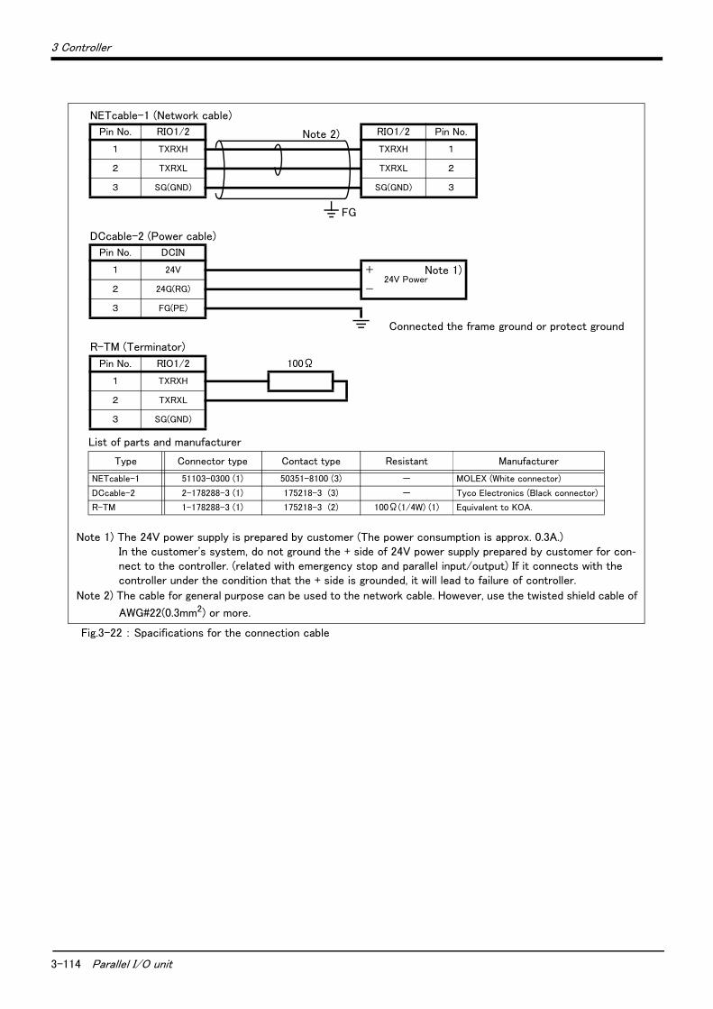
3-114 Parallel I/O unit
3 Controller
Fig.3-22 : Spacifications for the connection cable
NETcable-1 (Network cable)
Pin No. RIO1/2 RIO1/2 Pin No.
1 TXRXH TXRXH 1
2 TXRXL TXRXL 2
3 SG(GND) SG(GND) 3
FG
DCcable-2 (Power cable)
Pin No. DCIN
1 24V +24V Power
2 24G(RG) -
3 FG(PE)
Connected the frame ground or protect ground
R-TM (Terminator)
Pin No. RIO1/2 100Ω
1 TXRXH
2 TXRXL
3 SG(GND)
List of parts and manufacturer
Type Connector type Contact type Resistant Manufacturer
NETcable-1 51103-0300 (1) 50351-8100 (3) - MOLEX (White connector)
DCcable-2 2-178288-3 (1) 175218-3 (3) - Tyco Electronics (Black connector)
R-TM 1-178288-3 (1) 175218-3 (2) 100Ω(1/4W) (1) Equivalent to KOA.
Note 2)
Note 1)
Note 1) The 24V power supply is prepared by customer (The power consumption is approx. 0.3A.)In the customer's system, do not ground the + side of 24V power supply prepared by customer for con-nect to the controller. (related with emergency stop and parallel input/output) If it connects with the controller under the condition that the + side is grounded, it will lead to failure of controller.
Note 2) The cable for general purpose can be used to the network cable. However, use the twisted shield cable of
AWG#22(0.3mm2) or more.
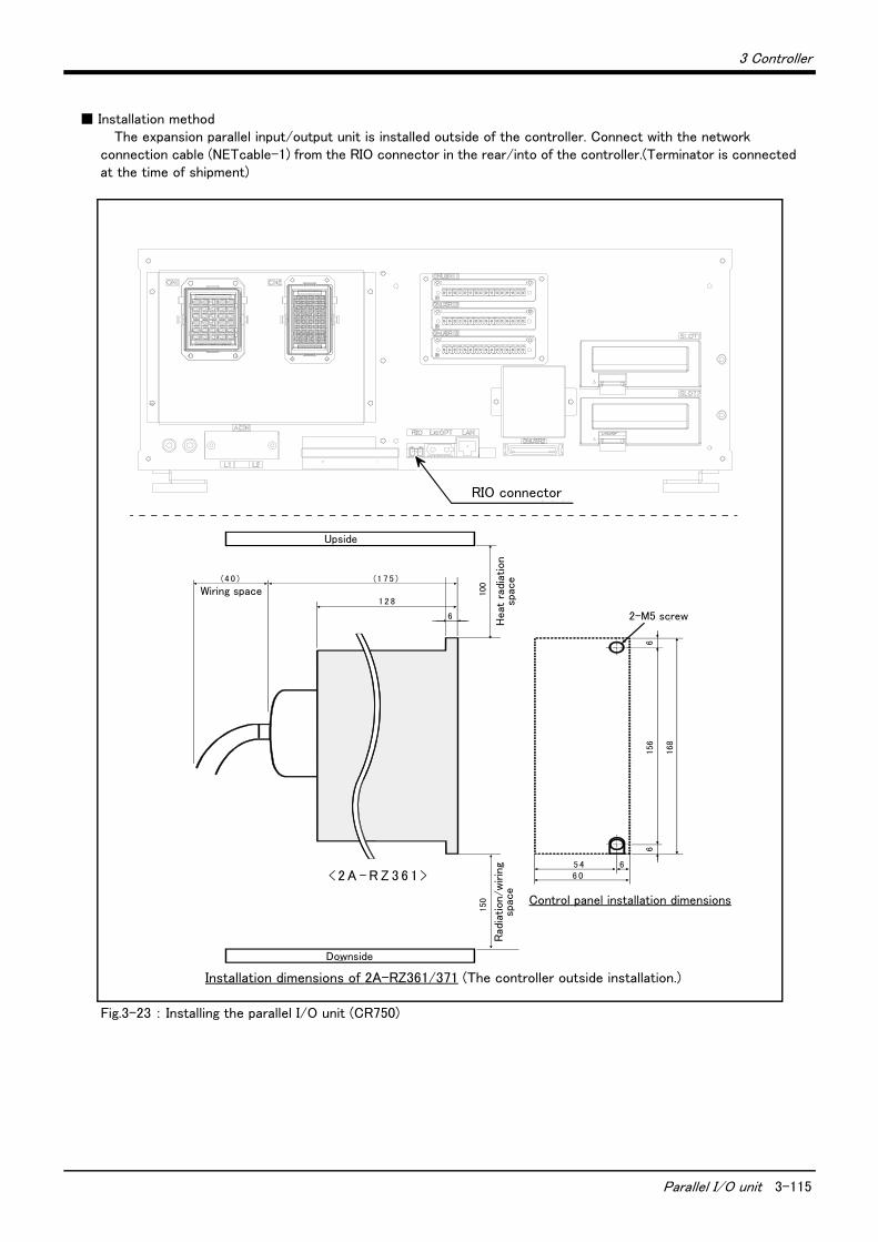
3 Controller
Parallel I/O unit 3-115
■ Installation methodThe expansion parallel input/output unit is installed outside of the controller. Connect with the network
connection cable (NETcable-1) from the RIO connector in the rear/into of the controller.(Terminator is connected at the time of shipment)
Fig.3-23 : Installing the parallel I/O unit (CR750)
RIOコネクタ
6 054 6
放熱
、配
線余
裕
150
6156
2 - M 5 ネ ジ
6
168
放熱
余裕
1 2 8
(1 7 5 )
100
天
配 線 余 裕(4 0 )
地
< 2 A - R Z 3 6 1 >
制 御 盤 取 付 寸 法
2 A - R Z 3 6 1 の 取 付 寸 法
6
Installation dimensions of 2A-RZ361/371 (The controller outside installation.)
RIO connector
Upside
Wiring space
Heat
rad
iation
spac
e
2-M5 screw
Downside
Rad
iation/w
irin
g sp
ace
Control panel installation dimensions
3-116 Parallel I/O unit
3 Controller
Fig.3-24 : Connection method of expansion parallel I/O unit (CR750)
局番設定 1 . . . 6
<CN100><CN300>
局番設定 7
<CN100>
<CN300>
NETcable-1ケーブル
R-TMターミネータ
パラレル入出力ユニット 1 . . . . 6 パラレル入出力ユニット7
RIOコネクタ
DCINコネクタ
RIO2コネクタRIO1コネクタ
NETcable-1ケーブル
DCcable-2ケーブル
RIO2コネクタ
RIO1コネクタ
DCINコネクタ
前 面
FGFG
入出力ユニット底面コネクタ配置図
注)
注)
RIO2コネクタRIO1コネクタ
DCINコネクタ
DCcable-2ケーブル
100mm以内*1)
フェライトコア(CEのみ)
FG
*2)
20~30mm金属製ブレード部
シース シース
*2) ケーブルアースクランプ
シースはケーブルのコネクタ端から200~300mmの箇所を目安にカバーの着脱ができる程度の位置で剥いてください。※シールド線に傷をつけないようにご注意願います。
Connect the NET cable-1 to the RIO connector on the back of the controller. Each unit is connected to from adaisy chain.Always install a terminator (R-TM) to the last unit.Note) Use a shield cable for NET cable-1 as a measure against noise.
Always connect the shield to FG. Install the attached ferrite core in both ends. The unit could malfunction because of noise if the shield cable is not used.
RIO
Parallel I/O unit 1 . . . 6 Parallel I/O unit 7
Note)NETcable-1cable
RIO1 connector
RIO1 connector RIO2 connector RIO1 connector RIO2 connector
Note)NETcable-1cable
DCcable-2cable
DCcable-2cable
RIO2 connector
DCIN connector
R-TMterminator
I/O unit the bottom connector layout
Within 100mm
Front side
Metal braid section
Sheath Sheath
Peel the sheath in the position about 200-300mm from the connector end of the cable, so you can install and remove the cover.* Don't damage the shield line.
Grounding terminal position
Station No.
setting
1 . . . 6
Station No.
setting
7
DCINconnector
DCINconnector
*1) Install the ferrite core in within 100mm from each connector.
Ferrite core(Only for the CE marking/KC mark specification)Pass twice
3 Controller
Parallel I/O unit 3-117
■ Pin arrangement of the connector
Fig.3-25 : Pin arrangement of the parallel I/O unit
■ Assignment of pin number and signalThe assignment range of the general-purpose input-and-output signal is fixed by the setup of the station number.
Table 3-23 : Assignment of pin number and signal
The connector pin number of the parallel I/O unit of the station number 0 and signal number assignment are shown in Table 3-24 and Table 3-25. If it is set as other station number, please interpret and utilize.
Unit Number Station number
CN100 CN300
1st set 0 Input : 0 to 15Output : 0 to 15
Input : 16 to 31Output : 16 to 31
2nd set 1 Input : 32 to 47Output : 32 to 47
Input : 48 to 63Output : 48 to 63
3rd set 2 Input : 64 to 79Output : 64 to 79
Input : 80 to 95Output : 80 to 95
4th set 3 Input : 96 to 111Output : 96 to 111
Input : 112 to 127Output : 112 to 127
5th set 4 Input : 128 to 143Output : 128 to 143
Input : 144 to 159Output : 144 to 159
6th set 5 Input : 160 to 175Output : 160 to 175
Input : 176 to 191Output : 176 to 191
7th set 6 Input : 192 to 207Output : 192 to 207
Input : 208 to 223Output : 208 to 223
8th set 7 Input : 224 to 239Output : 224 to 239
Input : 240 to 255Output : 240 to 255
*2A-RZ361/2 A-RZ371 are 32/32 input-and-output units. (One-station occupancy)
50
26
25
1
Channel No. setting
TXD LED display
Input 0 to 15Output 0 to 15
<CN100>
<CN300> Input 16 to 31Output 16 to 31

3-118 Parallel I/O unit
3 Controller
■ Parallel I/O interface (First expansion unit)Table 3-24 : Connector CN100pin No. and signal assignment list (2A-CBL □□ )
PinNo.
Line color
Function name PinNo.
Line color
Function name
General-purpose Dedicated/power supply,
common General-purpose
Dedicated/power supply, common
1 Orange/Red A FG 26 Orange/Blue A FG
2 Gray/Red A 0V:For pins 4-7, 10-13 27 Gray/Blue A 0V:For pins 29-32, 35-38
3 White/Red A 12V/24V:For pins 4-7 28 White/Blue A 12V/24V:For pins 29-32
4 Yellow/Red A General-purpose output 0 Operating output Note1)
Note1) The dedicated signal is assigned at shipping. It can change with the parameter.
29 Yellow/Blue A General-purpose output 4
5 Pink/Red A General-purpose output 1 In servo ON output signal Note1)
30 Pink/Blue A General-purpose output 5
6 Orange/Red B General-purpose output 2 Error occurring output signal Note1)
31 Orange/Blue B General-purpose output 6
7 Gray/Red B General-purpose output 3 Operation rights output sig-
nal Note1) 32 Gray/Blue B General-purpose output 7
8 White/Red B 0V:For pins 4-7, 10-13 33 White/Blue B 0V:For pins 29-32, 35-38
9 Yellow/Red B 12V/24V:For pins 10-13 34 Yellow/Blue B 12V/24V:For pins 35-38
10 Pink/Red B General-purpose output 8 35 Pink/Blue B General-purpose output 12
11 Orange/Red C General-purpose output 9 36 Orange/Blue C General-purpose output 13
12 Gray/Red C General-purpose output 10 37 Gray/Blue C General-purpose output 14
13 White/Red C General-purpose output 11 38 White/Blue C General-purpose output 15
14 Yellow/Red C COM0:For pins 15-22 Note2)
Note2) Sink type:12V/24V(COM),Source type:0V(COM)
39 Yellow/Blue C COM1:For pins 40-47 Note2)
15 Pink/Red C General-purpose input 0 Stop input Note3)
Note3) The dedicated input signal (STOP) is assigned at shipping. The signal number is fixing.
40 Pink/Blue C General-purpose input 8
16 Orange/Red D General-purpose input 1 Servo OFF input signal Note1)
41 Orange/Blue D General-purpose input 9
17 Gray/Red D General-purpose input 2 Error reset input signal Note1)
42 Gray/Blue D General-purpose input 10
18 White/Red D General-purpose input 3 Start input Note1) 43 White/Blue D General-purpose input 11
19 Yellow/Red D General-purpose input 4 Servo ON input signal Note1) 44 Yellow/Blue D General-purpose input 12
20 Pink/Red D General-purpose input 5 Operation rights input sig-
nal Note1) 45 Pink/Blue D General-purpose input 13
21 Orange/Red E General-purpose input 6 46 Orange/Blue E General-purpose input 14
22 Gray/Red E General-purpose input 7 47 Gray/Blue E General-purpose input 15
23 White/Red E Reserved 48 White/Blue E Reserved
24 Yellow/Red E Reserved 49 Yellow/Blue E Reserved
25 Pink/Red E Reserved 50 Pink/Blue E Reserved

3 Controller
Parallel I/O unit 3-119
Table 3-25 : Connector CN300pin No. and signal assignment list (2A-CBL □□ )
PinNo.
Line color
Function name PinNo.
Line color
Function name
General-purpose Dedicated/power supply,
common General-purpose
Dedicated/power supply, common
1 Orange/Red A FG 26 Orange/Blue A FG
2 Gray/Red A 0V:For pins 4-7, 10-13 27 Gray/Blue A 0V:For pins 29-32, 35-38
3 White/Red A 12V/24V:For pins 4-7 28 White/Blue A 12V/24V:For pins 29-32
4 Yellow/Red A General-purpose output 16 29 Yellow/Blue A General-purpose output 20
5 Pink/Red A General-purpose output 17 30 Pink/Blue A General-purpose output 21
6 Orange/Red B General-purpose output 18 31 Orange/Blue B General-purpose output 22
7 Gray/Red B General-purpose output 19 32 Gray/Blue B General-purpose output 23
8 White/Red B 0V:For pins 4-7, 10-13 33 White/Blue B 0V:For pins 29-32, 35-38
9 Yellow/Red B 12V/24V:For pins 10-13 34 Yellow/Blue B 12V/24V:For pins 35-38
10 Pink/Red B General-purpose output 24 35 Pink/Blue B General-purpose output 28
11 Orange/Red C General-purpose output 25 36 Orange/Blue C General-purpose output 29
12 Gray/Red C General-purpose output 26 37 Gray/Blue C General-purpose output 30
13 White/Red C General-purpose output 27 38 White/Blue C General-purpose output 31
14 Yellow/Red C COM0:For pins 15-22Note1)
Note1) Sink type:12V/24V(COM),Source type:0V(COM)
39 Yellow/Blue C COM1:For pins 40-47 Note1)
15 Pink/Red C General-purpose input 16 40 Pink/Blue C General-purpose input 24
16 Orange/Red D General-purpose input 17 41 Orange/Blue D General-purpose input 25
17 Gray/Red D General-purpose input 18 42 Gray/Blue D General-purpose input 26
18 White/Red D General-purpose input 19 43 White/Blue D General-purpose input 27
19 Yellow/Red D General-purpose input 20 44 Yellow/Blue D General-purpose input 28
20 Pink/Red D General-purpose input 21 45 Pink/Blue D General-purpose input 29
21 Orange/Red E General-purpose input 22 46 Orange/Blue E General-purpose input 30
22 Gray/Red E General-purpose input 23 47 Gray/Blue E General-purpose input 31
23 White/Red E Reserved 48 White/Blue E Reserved
24 Yellow/Red E Reserved 49 Yellow/Blue E Reserved
25 Pink/Red E Reserved 50 Pink/Blue E Reserved

3-120 Parallel I/O unit
3 Controller
<Reference> The example of connection with our PLC
Table 3-26 : Connection with a Mitsubishi PLC (Example of sink type)
Table 3-27 : Connection with a Mitsubishi PLC (Example of source type)
60mA (24/12V)
Output
Fuse(0V)
(COM)
QX41(Mitsubishi programmablecontroller)
QY41P(Mitsubishi programmablecontroller)
+24V
COM
X
Y
24V
……
Input
Parallel I/O interface (Output)
(Input)
3.3K
Output
Input
Externalpower supply
24G(24GND)COM
Externalpower supply
24V
……
<Sink>
*The input/output circuit external power supply (24 VDC) must be prepared by the customer.
Note) In the customer's system, do not ground the + side of 24V power supply prepared by customer for connect to the controller. (related with emergency stop and parallel input/output) If it connects with the controller under the condition that the + side is grounded, it will lead to failure of controller.
<Source>
60mA (24/12V)
Output
Output
Fuse
(0V)
(COM)
QX41
24G(24GND)
+24V
COM
External power supply
X
Y
24V
24V
(Output)
(Input)
3.3K
External power supply
Input
Input
……
……
QY81P
Parallel I/O interface
(Output) (Mitsubishi programmablecontroller)
(Mitsubishi programmablecontroller)
*The input/output circuit external power supply (24 VDC) must be prepared by the customer.
Note) In the customer's system, do not ground the + side of 24V power supply prepared by customer for connect to the controller. (related with emergency stop and parallel input/output) If it connects with the controller under the condition that the + side is grounded, it will lead to failure of controller.
3 Controller
External I/O cable 3-121
(5) External I/O cable
■ Order type: 2A-CBL □□ Note) The numbers in the boxes □□ refer to the length. (05: 5m、 15: 15m)
■ OutlineThis is the dedicated cable used to connect an external peripheral device to the con-nector on the parallel input/output unit.
One end matches the connector on the parallel input/output unit, and the other end is free. Connect the peripheral device's input/output signal using the free end.
One cable correspond to the input 16 points and output 16 points.
Two cables are needed to connection of (input 32 points and output 32 points) with built-in standard.
■ ConfigurationTable 3-28 : Configuration device
■ SpecificationsTable 3-29 : Specifications
■ Connector pin numbers and cable colorsTable 3-30 : Connector pin numbers and cable colors
Part name Type Qty. Mass(kg)Note1)
Note1) Mass indicates one set.
Remarks
External I/O cable 2A-CBL □□ 1pc. 0.7(5m)
1.84(15m)5m or 15m
Items Specifications
Number of cables x cable size 50 pairs x AWG #28
Total length 5m or 15m
Pin no. Cable colors Pin
no. Cable colors Pin no. Cable colors Pin
no. Cable colors Pin no. Cable colors
1 Orange/Red A 11 Orange/Red C 21 Orange/Red E 31 Orange/Blue B 41 Orange/Blue D
2 Gray/Red A 12 Gray/Red C 22 Gray/Red E 32 Gray/Blue B 42 Gray/Blue D
3 White/Red A 13 White/Red C 23 White/Red E 33 White/Blue B 43 White/Blue D
4 Yellow/Red A 14 Yellow/Red C 24 Yellow/Red E 34 Yellow/Blue B 44 Yellow/Blue D
5 Pink/Red A 15 Pink/Red C 25 Pink/Red E 35 Pink/Blue B 45 Pink/Blue D
6 Orange/Red B 16 Orange/Red D 26 Orange/Blue A 36 Orange/Blue C 46 Orange/Blue E
7 Gray/Red B 17 Gray/Red D 27 Gray/Blue A 37 Gray/Blue C 47 Gray/Blue E
8 White/Red B 18 White/Red D 28 White/Blue A 38 White/Blue C 48 White/Blue E
9 Yellow/Red B 19 Yellow/Red D 29 Yellow/Blue A 39 Yellow/Blue C 49 Yellow/Blue E
10 Pink/Red B 20 Pink/Red D 30 Pink/Blue A 40 Pink/Blue C 50 Pink/Blue E

3-122 External I/O cable
3 Controller
■ Connections and outside dimensionsThe sheath of each signal cable (50 lines) is color indicated and marked with dots. Refer to the cable color speci-fications in "Table 3-30: Connector pin numbers and cable colors" when making the connections.
Fig.3-26 : Connections and outside dimensions
(Eg.) Pin number: color indication
1 : Orange / Red / A
Type of dot mark (see figure below)
Color of dot mark
Color of sheath
Type of dot mark
A type
B type
C type
D type
E type
F type
G type
H type
I type
J type
Dot pattern
Receptacle type (PCB side):57AE-40500-21D(D8)
Plug type (cable side):57YE-30500-2(D8)
……DDK
Maker
……DDK
26
5000
66
50 25
1
18.5
1
18.5
18.5
Continuous
18.5
1.5
1.5
1.5
1.5
18.5
3
3
3
18.5
18.5
18.5
7.5
7.5
Continuous
35.7
13.54
16.2 9.27
76. 7
4
64.5
3
51.8
16
2.1
59
Type of dot mark Dot pattern
Note1) The type of the plug shows the specification of this cable. The following connector is recommended when user make the cable. ・Plug type (cable side) : 57E series (Soldering type).....................................................DDK 57FE series (Flat cable pressure connection type)......DDK
Note1)

3 Controller
CC-Link interface 3-123
(6) CC-Link interface
■ Order type: ● 2D-TZ576
■ OutlineThe CC-Link interface is the optioninterface to not only add bit data to the robot controller. but also to add CC-Link field network function that allows cyclic transmission of word data.
■ ConfigurationTable 3-31 : Configuration device
Table 3-32 : Procured by the customer
Fig.3-27 : Example of CC-Link Product Configuration
Part name Type Qty. Mass(kg)Note1)
Note1) Mass indicates one set.
Remarks
CC-Link interface TZ576 1 0.6
Manual BFP-A8701 1 -
Ferrite core E04SR301334 2 -
Be sure to install this for noise countermeasure.Cable clamp AL4 2 -
AL5 2 -
Part name Type Qty. Remarks
Master station
QJ61BT11(Q series)
1 FX series products are not supported.
QJ61BT11N(Q series)
AJ61QBT11(QnA series)
A1SJ61QBT11(QnAS series)
AJ61BT11(A series)
A1SJ61BT11(AnS series)
A80BD-J61BT11(personal computer board)
Communication cable - 1Shielded 3-core twisted cable
This cable may be manufactured by the customer.
Terminal resistor - 1 110Ω or 130Ω is recommended.
ロボットコントローラ(図はCR751)
CC-Link インタフェースカード(本オプション)
ロボット本体
表示器
I/Oユニット
シーケンサ
インバータ
パソコンパートナーメーカーの機器
Robot arm
InverterI/O unit
Display Sequencer
Personal computerPartner manufacturer’s device
CC-Link interface (This option)
Controller(The figure is CR751)
3-124 CC-Link interface
3 Controller
■ SpecificationsTable 3-33 : Specifications
Item Specifications Remarks
Communication function Bit data and word data can be transmitted. Word data are used by the registers.
Station type Intelligent device station Note1)
Note1) The CC-Link interface supports neither the transient transmission function nor the FX series.
Support station Local station No master station function
The version corresponding to CC-Link Ver.2 The extended cyclic setup is possible.
Mountable option slot Slot 1, 2
Number of mountable CC-Link interface cards 1 Multiple CC-Link interface cards cannot be
inserted.
Number of stations 1 to 64 stations When four stations are occupied, continuous
station numbers are used. The station
numbers are set by a DIP switch.
Transmission speed 10M/5M/2.5M/625K/156K bps This is set by the rotary SW.
Station number 1 to 64 When two or more stations are occupied,
continuous station numbers are used.Number of occupied stations 1/2/3/4
Extended cyclic setup 1/2/4/8
Maximum link point Remote I/O
(RX, RY).
Each 896 points The two last cannot be used.
Remote register
(RWr, RWw)
Each 128 register 16 bits/register
Extended cyclic setup - 1 fold
setup
2 fold
setup
3 fold
setup
4 fold
setup
Link point
per set
When one
station is
occupied
Remote I/O
(RX, RY).
32 point 32 point 64 point 128 point
Remote register
( RWw)
4 word 8 word 16 word 32 word
Remote register
(RWr)
4 word 8 word 16 word 32 word
When two
stations is
occupied
Remote I/O
(RX, RY).
64 point 96 point 192 point 384 point
Remote register
( RWw)
8 word 16 word 32 word 64 word
Remote register
(RWr)
8 word 16 word 32 word 64 word
When three
stations is
occupied
Remote I/O
(RX, RY).
96 point 160 point 320 point 640 point
Remote register
( RWw)
12 word 24 word 48 word 96 word
Remote register
(RWr)
12 word 24 word 48 word 96 word
When four
stations is
occupied
Remote I/O
(RX, RY).
128 point 224 point 448 point 896 point
Remote register
( RWw)
16 word 32 word 64 word 128 word
Remote register
(RWr)
16 word 32 word 64 word 128 word
Number of the maximum occupancy station 4 stations
The I/O first number of the robot controller. No. 6000 -.
The number corresponding to the station
number by the setup of the parameter
"CCFIX."
3 Controller
CC-Link interface 3-125
■ Functions(1) Communication function
・ The number of usable points is 896 points maximum for bit control and 128 points maximum for word control.
(2) Easy setup・ The CC-Link interface card can be set by a rotary switch or DIP switch.・No separate space is required to mount the CC-Link interface card as it is embedded in the robot controller (canonly be mounted into slot 2).
・ Easy wiring since only four terminals need to be connected.・ Dedicated commands have been added to MELFA-BASIC V (robot programming language); thus, no complexinterface programming is required.
(3) High-speed response・The link scan time when connecting 64 stations is approximately 7.2 ms, achieving superior high-speed responseperformance.
・ A transmission speed can be selected from 10M, 5M, 2.5M, 625K and 156K bps according to the transmissiondistance.

3-126 Controller protection box
3 Controller
(7) Controller protection box
■ Order type: ● CR750-MB
■ Outline
By putting the controller in this box, the controller can be protected from oil mist environment.
Use this option, when the controller is installed where environment is oil mist such as machine shop etc. Therefore, the operation of installing and removing the T/B, and changing the mode switch can be done, with the controller put in.
■ ConfigurationTable 3-34 : Configuration equipment and types
■ SpecificationsTable 3-35 : Specifications
(1) The robot must be grounded by the customer.(2) The cable for primary power supply connection and the grounding cable are customer preparations.
Part name Type Qty. Mass (Kg)Note1)
Note1) Mass indicates one set.
備考
Controller protection box CR750-MB 1
22
power supply wiring cable 3 For connection between the power supply relay
terminal and controller inside this box
Grounding cable 1 For connection between the grounding terminal and
controller inside this box
Seal for the serial number copy 1
Protection seal clear 1
Cable tie T50L 4
Screw for fixing of the controller
mounting plate
M4x8 4
Item Unit Specifications Remarks
Outside dimension mm 500(W)×725(D)×250(H) Excluding protrusions
Mass Kg 22
Construction Self-contained floor type IP54
Grounding Ω 100 or less (class D grounding)
Paint color Dark gray

3 Controller
Controller protection box 3-127
■ Outside dimension and controller setting position
Fig.3-28 : Outside dimension and controller setting position
Cable cover
Controller setting position
Drain hole
Rubber foot fixa-tion screw for placing vertically (Four places)
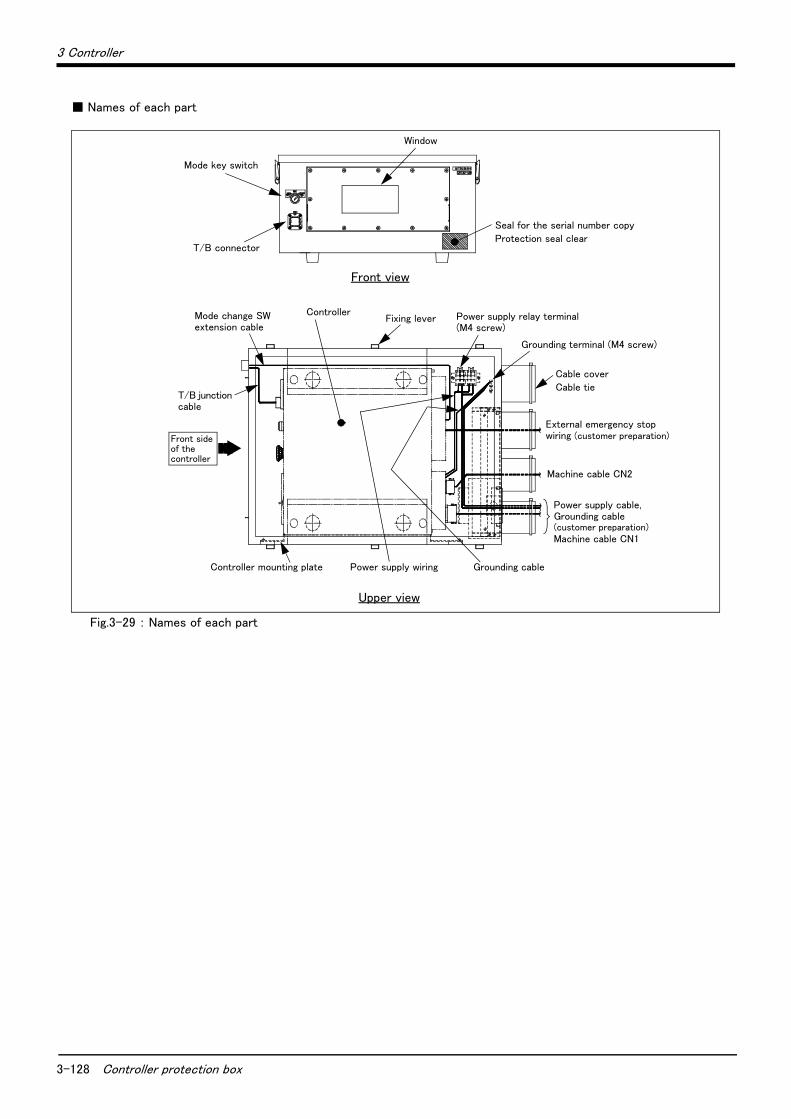
3-128 Controller protection box
3 Controller
■ Names of each part
Fig.3-29 : Names of each part
Window
Seal for the serial number copy
Protection seal clear
Cable cover
Cable tie
External emergency stop wiring (customer preparation)
Machine cable CN2
Power supply cable, Grounding cable(customer preparation)Machine cable CN1
Grounding terminal (M4 screw)
Power supply relay terminal (M4 screw)
Fixing leverControllerMode change SW
extension cable
T/B junction cable
Controller mounting plate Power supply wiring
Mode key switch
T/B connector
Front side of the controller
Front view
Upper view
Grounding cable

3 Controller
Controller protection box 3-129
■ Wiring system diagram
Fig.3-30 : Wiring system diagram
(L1)
FG FG FG
FG
(L2)
(L1)
ACIN
CN1
CN2
CNUSR11/12
(L2)
<Single phase: RV-4F series>
<Single phase/Three phase: RV-7F/13F series>
(L1)
(L2)
FG FG FG
FG
(L2)
(L1)
ACIN
CN1
CN2
CNUSR11/12
(L3)
(L3)
Note1) When using the controller for the three phases with the single-phase power supply, connect the primary power supply to L1 and L2 electric terminal of the protection box so that the power supply may be supplied to the heat-exchanger AC fan of the protection box.Connects with L1 and L3 electric terminal to the ACIN terminal block of the controller. Refer to the separate manual "Controller setup, basic operation, and maintenance" for detail of connecting the power cable and the grounding cable.
Power supply wiringController protection box Terminal
Power supply cable
Grounding cable
Grounding cable
Grounding terminal
AC fan
Controller
Power supply wiringController protection box
Power supply cable
Grounding cable
Grounding cableGrounding terminal
AC fan
Controller
Terminal Note1)

3-130 Controller protection box
3 Controller
■ Installation dimensions
Fig.3-31 : Installation dimensions
<<Placed horizontally>
150mm or more
<Placed vertically>
30mm or more
150mm or more
150mm or more
30mm or more
150mm or more
150mm or more
150mm or more
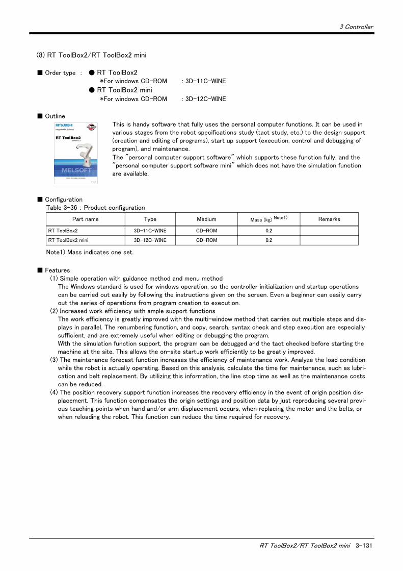
3 Controller
RT ToolBox2/RT ToolBox2 mini 3-131
(8) RT ToolBox2/RT ToolBox2 mini
■ Order type : ● RT ToolBox2*For windows CD-ROM : 3D-11C-WINE
● RT ToolBox2 mini*For windows CD-ROM : 3D-12C-WINE
■ OutlineThis is handy software that fully uses the personal computer functions. It can be used in various stages from the robot specifications study (tact study, etc.) to the design support (creation and editing of programs), start up support (execution, control and debugging of program), and maintenance.
The "personal computer support software" which supports these function fully, and the "personal computer support software mini" which does not have the simulation function are available.
■ ConfigurationTable 3-36 : Product configuration
■ Features(1) Simple operation with guidance method and menu method
The Windows standard is used for windows operation, so the controller initialization and startup operations can be carried out easily by following the instructions given on the screen. Even a beginner can easily carry out the series of operations from program creation to execution.
(2) Increased work efficiency with ample support functionsThe work efficiency is greatly improved with the multi-window method that carries out multiple steps and dis-plays in parallel. The renumbering function, and copy, search, syntax check and step execution are especially sufficient, and are extremely useful when editing or debugging the program.With the simulation function support, the program can be debugged and the tact checked before starting the machine at the site. This allows the on-site startup work efficiently to be greatly improved.
(3) The maintenance forecast function increases the efficiency of maintenance work. Analyze the load condition while the robot is actually operating. Based on this analysis, calculate the time for maintenance, such as lubri-cation and belt replacement. By utilizing this information, the line stop time as well as the maintenance costs can be reduced.
(4) The position recovery support function increases the recovery efficiency in the event of origin position dis-placement. This function compensates the origin settings and position data by just reproducing several previ-ous teaching points when hand and/or arm displacement occurs, when replacing the motor and the belts, or when reloading the robot. This function can reduce the time required for recovery.
Part name Type Medium Mass (kg) Note1)
Note1) Mass indicates one set.
Remarks
RT ToolBox2 3D-11C-WINE CD-ROM 0.2
RT ToolBox2 mini 3D-12C-WINE CD-ROM 0.2

3-132 RT ToolBox2/RT ToolBox2 mini
3 Controller
■ FunctionsTable 3-37 : Functions
Function Functional existenceNote1)
Note1) The functions included with the RT ToolBox2 and the RT ToolBox2 mini are shown below. ○ : Function provided ×: Function not provided
Details
Compatible model ○ ○ Personal computer running Microsoft Windows2000/XP/Vista/7. Note2)
Note2) Recommend corresponding to CE Marking, an FCC standard, and a VCCI standard.
Program editing
functions
Editing functions
○ ○
・ MELFA BASIC V language compatible
・ Multiple editing screen simultaneously display
・ Command input, comment writing
・ Position data editing
・ File operation (writing to controller, floppy disk, personal computer)
・ Search and replace function (using characters, line Nos., labels)
・ Copy, cut, paste, insert (per character, line), undo (per command
statement, position conversion)
・ Line No. automatic generation, renumbering
・ Batch syntax check
・ Command template
・ Position conversion batch editing
・ Position variable template
・ Print, print preview
Control func-tions
○ ○・ Program file control (list, copy, movement, delete, content compari-son, name change, protect)
Debugging func-tions ○ ○
・ Direct editing of program in controller
・ Confirmation of robot program operation (step execution, direct exe-cution)
Simulation func-tion ○ ×
・ Off-line simulation of robot program operation using CG (computer
graphics)
・ Tact time calculation
Monitor func-tions
○ ○
・ Robot operation monitor (robot operation state, stop signal, error
monitor, program monitor (execution program, variables), general-pur-pose input/output signals (forced output possible), dedicated input/
output signals, operation confirmation (operation range, current posi-tion, hand, etc.)
・ Operation monitor (working time statistics, production information,
robot version)
・ Servo monitor (load)
Maintenance
function ○ ○
・ Parameter setting
・ Batch, divided backup
RT ToolBox2 mini
(3D-12C-WINE)
RT ToolBox2
(3D-11C-WINE)
3 Controller
Instruction Manual(bookbinding) 3-133
(9) Instruction Manual(bookbinding)
■ Order type: ● 5F-FF01-PE01...............RV-4F-D/7F-D/13F-D series
■ Outline
This is a printed version of the CD-ROM (instruction manual) supplied with this product.
■ ConfigurationTable 3-38 : Product configuration
Name TypeMass (Kg)
Note1)
Note1) Mass indicates one set.
Specifications
Instruction ManualRV-4F-D/7F-D/13F-D:
5F-FF01-PE012.6
The instructions manual set of RV-4F-D series, RV-
7F-D series and RV-13F-D series.
Safety Manual BFP-A8006 - Items relating to safety in handling the robot
Standard Specifications BFP-A8931 - Specification of the robot arm and controller
Robot Arm Setup & Maintenance BFP-A8935 -Installation method of the robot arm, jog operation, and
maintenance and inspection procedures
Controller Setup, Basic Operation and Maintenance BFP-A8867 -Installation method of the controller, basic operation,
and maintenance and inspection procedures
Detailed Explanation of Functions and Operations BFP-A8869 -Functions of the controller and T/B, operation
method, and explanation of MELFA-BASIC V
Troubleshooting BFP-A8871 - Causes of errors occurred and their countermeasures
Additional axis function BFP-A8863 - Function of the additional axis, operation method.
Tracking Function Manual BFP-A8664 - Function of the Tracking, operation method.
GOT Direct Connection Extended Function BFP-A8849 -
Explains of data configuration of shared memory,
monitoring, and operating procedures, between the
GOT and controller.
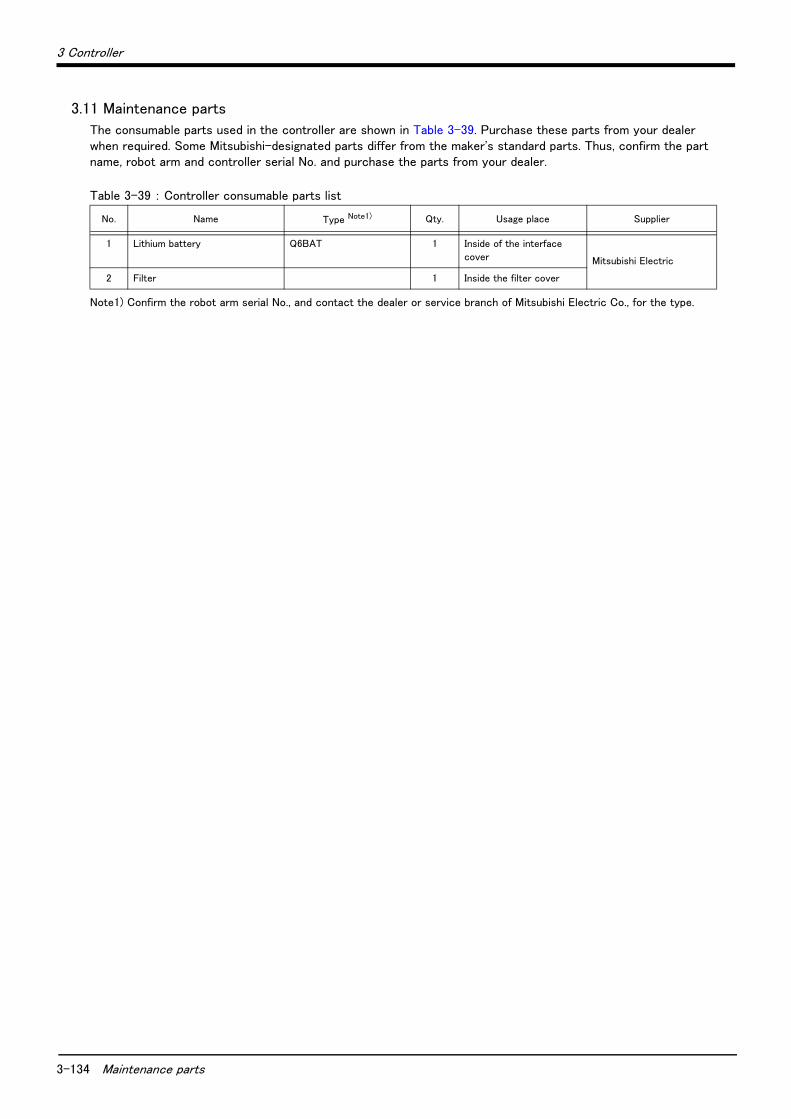
3-134 Maintenance parts
3 Controller
3.11 Maintenance parts
The consumable parts used in the controller are shown in Table 3-39. Purchase these parts from your dealer when required. Some Mitsubishi-designated parts differ from the maker's standard parts. Thus, confirm the part name, robot arm and controller serial No. and purchase the parts from your dealer.
Table 3-39 : Controller consumable parts list
No. Name Type Note1)
Note1) Confirm the robot arm serial No., and contact the dealer or service branch of Mitsubishi Electric Co., for the type.
Qty. Usage place Supplier
1 Lithium battery Q6BAT 1 Inside of the interface
cover Mitsubishi Electric
2 Filter 1 Inside the filter cover

4Software
List of commands 4-135
4 Software
4.1 List of commands
The available new functions in MELFA-BASIC V are given in Table 4-1.
Table 4-1 : List of MELFA-BASIC V commands
Type Class Function Input format (example)
Posi
tion a
nd
ope
ration c
ontr
ol
Joint interpolation Moves to the designated position with joint interpolation. Mov P1
Linear interpolation Moves to the designated position with linear interpolation. Mvs P1
Circular interpolation Moves along a designated arc (start point → passing point → start point
(end point)) with 3-dimensional circular interpolation (360 degrees).Mvc P1,P2,P1
Moves along a designated arc (start point → passing point → end point)
with 3-dimensional circular interpolation.Mvr P1,P2,P3
Moves along the arc on the opposite side of a designated arc (start point
→ reference point → end point) with 3-dimensional circular interpola-tion.
Mvr2 P1,P9,P3
Moves along a set arc (start point → end point) with 3-dimensional cir-cular interpolation.
Mvr3 P1,P9,P3
Speed designation Designates the speed for various interpolation operations with a per-centage (0.1% unit).
Ovrd 100
Designate the speed for joint interpolation operation with a percentage
(0.1% unit).JOvrd 100
Designates the speed for linear and circular interpolation with a numeri-cal value (mm/s unit).
Spd 123.5
Designates the acceleration/deceleration time as a percentage in
respect to the predetermined maximum acceleration/deceleration. (1%
unit)
Accel 50,80
Automatically adjusts the acceleration/deceleration according to the
parameter setting value.Oadl ON
Sets the hand and work conditions for automatic adjustment of the
acceleration/deceleration.Loadset 1,1
Operation Adds a process unconditionally to the operation. Wth
Adds a process conditionally to the operation. WthIf
Designates smooth operation. Cnt 1,100,200
Performance of movement is upgraded corresponding to the application. MvTune 4
Designates the positioning completion conditions with a No. of pulses. Fine 200
Designates the positioning completion conditions with a distance in a
straight lineFine 1, P
Designates the positioning completion conditions with a joint interpola-tion.
Fine 0.5, J, 2
Turns the servo power ON/OFF for all axes. Servo OFF
Limits the operation of each axis so that the designated torque is not
exceeded.Torq 4,10
Position control Designates the base conversion data. Base P1
Designates the tool conversion data. Tool P1
Float control The robot arm rigidity is lowered and softened. (XYZ coordinate system) Cmp Pos ,&B00000011
The robot arm rigidity is lowered and softened. (JOINT coordinate sys-tem)
Cmp Jnt ,&B00000011
The robot arm rigidity is lowered and softened. (TOOL coordinate sys-tem)
Cmp Tool ,&B00000011
The robot arm rigidity is returned to the normal state. Cmp Off
The robot arm rigidity is designated. CmpG 1.0,1.0,1.0,1.0,1.0,1.0,1.0,1.0
Pallet Defines the pallet. Def Plt 1,P1,P2,P3,P4,5,3,1
Operates the pallet grid point position. Plt 1,M1
Singular point pas-sage
Move to a specified position using linear interpolation passing through a
singular point.Mvs P1 Type 0,2

4-136 List of commands
4Software
Pro
gram
contr
ol
Branching Branches unconditionally to the designated place. GoTo 120
Branches according to the designated conditions. If M1=1 Then GoTo *L100
Else GoTo 20
End If
Repeats until the designated end conditions are satisfied. For M1=1 TO 10
Next M1
Repeats while the designated conditions are satisfied. While M1<10
WEnd
Branches corresponding to the designated expression value. On M1 GoTo *La1, *Lb2, *Lc3
Executes program block corresponding to the designated expression
value..
Select
Case 1
Break
Case 2
Break
End Select
Moves the program process to the next line. Skip
Collision detection Set to enable/disable the collision detection. ColChk ON/OFF
Set the detection level of the collision detection. ColLvl 100,80,,,,,,
Subroutine Executes the designated subroutine. (Within program) GoSub *L200
Returns from the subroutine. Return
Executes the designated program. CallP "P10",M1,P1
Defines the program argument executed with the CALLP command. FPrm M10,P10
Executes the subroutine corresponding to the designated expression
value.On M1 GoSub *La1, *Lb2, *Lc3
Interrupt Defines the interrupt conditions and process. Def Act 1, M1=1 GoTo *L100
Enables/disables the interrupt. Act 1=1
Defines the start line of the program to be executed when an interrupt is
generated from the communication line.On Com(1) GoSub *L100
Enables the interrupt from the communication line. Com(1) On
Disables the interrupt from the communication line. Com(1) Off
Stops the interrupt from the communication line. Com(1) Stop
Wait Designates the wait time, and the output signal pulse output time. (0.01s
unit)Dly 0.5
Waits until the variable becomes the designated value. Wait M_In(1)=1
Stop Stops the program execution. Hlt
Generates an error. During program execution, continue, stop or servo
OFF can be designated.Error 9000
End Ends the program execution. End
Han
d Hand open Opens the designated hand. HOpen 1
Hand close Closes the designated hand. HClose 1
Input/
out
put Assignment Defines the input/output variables. Def IO PORT1=BIT,0
Input Retrieves the general-purpose input signal. M1=M_In(1)
Output Calls out the general-purpose output signal.M_Out(1) =0
Par
alle
l exe
cution
Mechanism designa-tion
Acquires the mechanism with the designated mechanism No. GetM 1
Releases the mechanism with the designated mechanism No. RelM 1
Selection Selects the designated program for the designated slot. XLoad 2,"P102"
Start/stop Carries out parallel execution of the designated program. XRun 3,"100",0
Stops parallel execution of the designated program. XStp 3
Returns the designated program's execution line to the head and enters
the program selection enabled state.XRst 3
Type Class Function Input format (example)
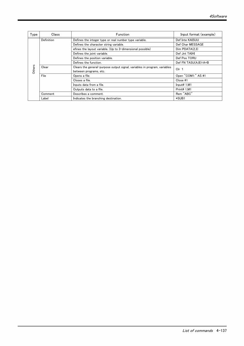
4Software
List of commands 4-137
Oth
ers
Definition Defines the integer type or real number type variable. Def Inte KAISUU
Defines the character string variable. Def Char MESSAGE
efines the layout variable. (Up to 3-dimensional possible) Dim PDATA(2,3)
Defines the joint variable. Def Jnt TAIHI
Defines the position variable. Def Pos TORU
Defines the function. Def FN TASU(A,B)=A+B
Clear Clears the general-purpose output signal, variables in program, variables
between programs, etc.Clr 1
File Opens a file. Open "COM1:" AS #1
Closes a file. Close #1
Inputs data from a file. Input# 1,M1
Outputs data to a file. Print# 1,M1
Comment Describes a comment. Rem "ABC"
Label Indicates the branching destination. *SUB1
Type Class Function Input format (example)

4-138 List of parameters
4Software
4.2 List of parameters
Show the main parameter in the Table 4-2.
Table 4-2 : List of parameters
Parameter Details
Standard tool coordinates. MEXTL Set the default value for the tool data.
Unit: mm or deg.
Standard base coordinates MEXBS Set the relation of the world coordinate system and robot coordinate system.
Unit: mm or deg.
XYZ operation range MEPAR Designate the overrun limit value for the world coordinate system.
JOINT operation range MEJAR Set the overrun limit value for each joint axis.
Free plane limit This is the overrun limit set with the free plane.
Create a plane with the three coordinates x1, y1, z1 to x3, y3, z3, and set the outer side of
the plane as the outside operation range (error). The following three types of parameters are
used.
SFC1P
:
SFC8P
Eight types of free plane limits can be set in SFC1P to SFC8P.
There are nine elements, set in the order of x1, y1, z1, x2, y2, z2, x3, y3, z3.
SFC1ME
:
SFC8ME
Designate which mechanism to use eight types of set free plane limits.
The mechanism No. to use is set with 1 to 3.
SFC1AT
:
SFC8AT
Set the validity of the eight types of set free plane limits.
(Valid 1/Valid 2/invalid = 1/-1/0)
User-defined area An area (cube) defined with two XYZ coordinate points can be designated and that area set
as the outside operation range. Furthermore, a signal can be output when the axis enters
that area. Up to 32 types of area can be designated.
AREA1CS
:
AREA32CS
Specify the coordinate system of the user definition area *.
0: Base coordinate system (conventional compatibility)
1: Robot coordinate system
AREA1P1
:
AREA32P1
Designated the 1st point of the area.
There are eight elements, set in the order of x, y, z, a, b, c, L1, L2.
(L1 and L2 are the additional axes.)
AREA1P2
:
AREA32P2
Designated the 2nd point of the area.
There are eight elements, set in the order of x, y, z, a, b, c, L1, L2.
(L1 and L2 are the additional axes.)
AREA1ME
:
AREA32ME
Designate which mechanism to use the 32 types of set area.
The mechanism No. to use is set with 1 to 3.
AREA1AT
:
AREA32AT
Designate the area check type.
(Invalid/zone/interference = 0/1/2)
Zone: The dedicated output signal USRAREA turns ON.
Interference: An error occurs..
Automatic return setting RETPATH Set to restart the program after returning to the interrupt position when resuming operation
after an interruption.
Buzzer ON/OFF BZR Designate whether to the turn buzzer ON or OFF.
Jog setting JOGJSP Designate the joint jog and step operation speed.
(Set dimension H/L amount, max. override.)
JOGPSP Designate the linear jog and step operation speed.
(Set dimension H/L amount, max. override.)
Jog speed limit value JOGSPMX Limit the operation speed during the teaching mode. Max. 250[mm/s]

4Software
List of parameters 4-139
Parameter Details
Hand type HANDTYPE Set the hand type of the single/double solenoid, and the signal No.
(Single/double = S/D)
Set the signal No. after the hand type. Example) D900
Stop input B contact desig-nation
INB Change the dedicated input (stop) to either of normal open or normal close.
User-designated origin USERORG Designate the user-designated origin position.
Program selection memory SLOTON Select the program selected previously when initializing the slot. The non-selected state will
be entered when not set.
Communication setting CBAU232 Set the baud rate.
CLEN232 Set the character length.
CPRTY232 Set the parity.
CSTOP232 Set the stop bit.
CTERM232 Set the end code.
Slot table SLT1
:
SLT32
Make settings (program name, operation type, order of priority, etc.) for each slot during slot
initialization.
No. of multi-tasks TASKMAX Designate the No. of programs to be executed simultaneously. (Max. 32)
Select the function of
singular point adjacent alarm
MESNGLSW Designate the valid/invalid of the singular point adjacent alarm.
(Invalid/Valid = 0/1)
When this parameter is set up "VALID", this warning sound is buzzing even if parameter:
BZR (buzzer ON/OFF) is set up "OFF".
Display language. LNG Change the language to display on the LCD display of teaching pendant.
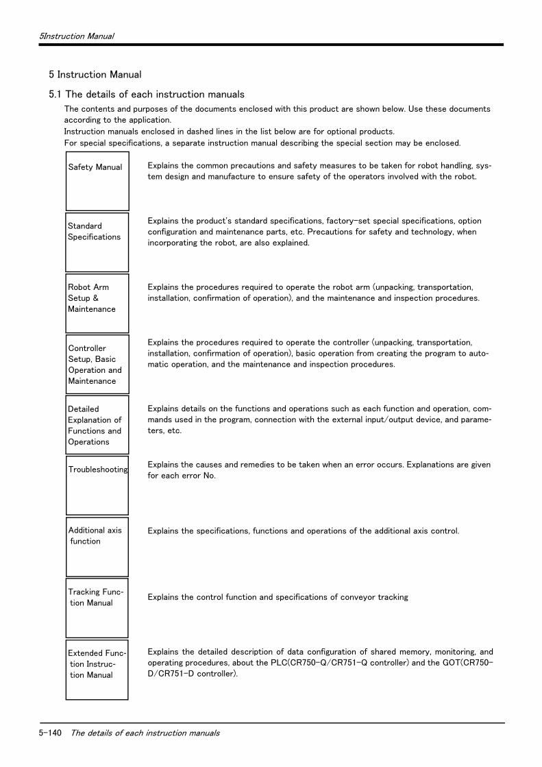
5-140 The details of each instruction manuals
5Instruction Manual
5 Instruction Manual
5.1 The details of each instruction manuals
The contents and purposes of the documents enclosed with this product are shown below. Use these documents according to the application.
Instruction manuals enclosed in dashed lines in the list below are for optional products.
For special specifications, a separate instruction manual describing the special section may be enclosed.
Explains the common precautions and safety measures to be taken for robot handling, sys-tem design and manufacture to ensure safety of the operators involved with the robot.
Explains the product's standard specifications, factory-set special specifications, option configuration and maintenance parts, etc. Precautions for safety and technology, when incorporating the robot, are also explained.
Explains the procedures required to operate the robot arm (unpacking, transportation, installation, confirmation of operation), and the maintenance and inspection procedures.
Explains the procedures required to operate the controller (unpacking, transportation, installation, confirmation of operation), basic operation from creating the program to auto-matic operation, and the maintenance and inspection procedures.
Explains details on the functions and operations such as each function and operation, com-mands used in the program, connection with the external input/output device, and parame-ters, etc.
Explains the causes and remedies to be taken when an error occurs. Explanations are given for each error No.
Explains the specifications, functions and operations of the additional axis control.
Explains the control function and specifications of conveyor tracking
Explains the detailed description of data configuration of shared memory, monitoring, andoperating procedures, about the PLC(CR750-Q/CR751-Q controller) and the GOT(CR750-D/CR751-D controller).
Safety Manual
StandardSpecifications
Robot ArmSetup &Maintenance
ControllerSetup, BasicOperation andMaintenance
Detailed Explanation ofFunctions andOperations
Troubleshooting
Additional axis function
Tracking Func-tion Manual
Extended Func-tion Instruc-tion Manual

6Safety
Safety 6-141
6 Safety
6.1 Safety
Measures to be taken regarding safety of the industrial robot are specified in the "Labor Safety and Sanitation Rules". Always follow these rules when using the robot to ensure safety.
6.1.1 Self-diagnosis stop functionsThis robot has the self-diagnosis stop functions shown in Table 6-1 and the stop functions shown in Table 6-2 for safe use.
Table 6-1 : Self-diagnosis stop functions
Table 6-2 : List of stop functions
No. Function Details Remarks
1 Overload protection func-tion
Activates when the total servo current time exceeds the specified value.
The drive circuit is shut off. The robot stops, and an alarm displays.
2 Overcurrent diagnosis function
Activates when an overcurrent flows to the motor circuit.
The drive circuit is shut off. The robot stops, and an alarm displays.
3 Encoder disconnection diagnosis function
Activates when the encoder cable is disconnected. The drive circuit is shut off. The robot stops, and an alarm displays.
4 Deflection over diagnosis function
Activates when an error occurs between the com-mand value and actual position, and the error exceeds the specified amount.
The drive circuit is shut off. The robot stops, and an alarm displays.
5 AC power voltage drop diagnosis function
Activates when the AC power voltage drops below the specified value.
The drive circuit is shut off. The robot stops, and an alarm displays.
6 CPU error detection func-tion
Activates when an error occurs in the CPU. The drive circuit is shut off. The robot stops, and an alarm displays.
7 Overrun prevention function
Software limit detection
This is the limit provided by the software to enable operation only in the operation range.
The drive circuit is shut off. The robot stops, and an alarm displays.
Mechanical stopper
This is the mechanical stopper provided outside the software.
The robot mechanically stops, and function 1 or 2 activates.
Stopfunction
Operationpanel
Teaching pendant
Externalinput Details
Emergencystop
◯ ◯ ◯ This is the stop with the highest degree of emergency. The servo power is shut off, and the mechanical brakes (all axes) activate to stop the robot.To recover, reset the alarm, and turn the servo ON with the servo ON command.
Stop ◯ ◯ ◯
This is a stop operation with a high degree of emergency. The robot immediately decelerates and stops.Note that the servo power is not shut off. Use this when using the collision evasion sensor, etc.
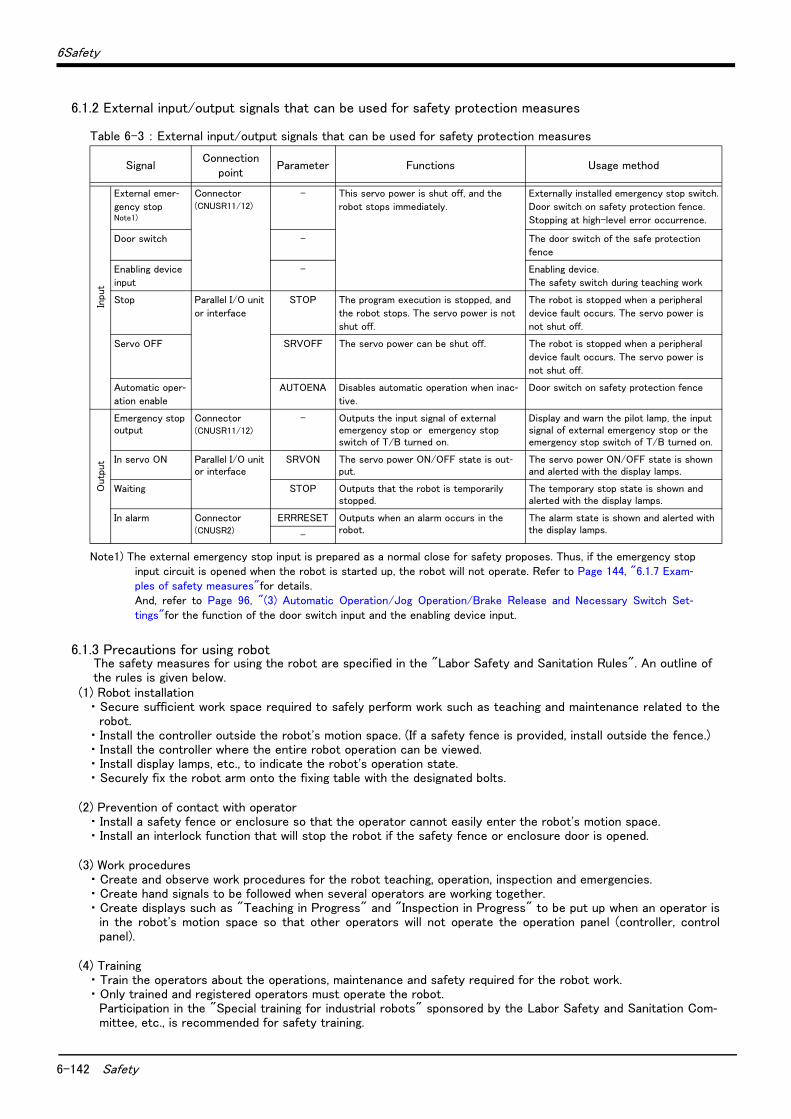
6-142 Safety
6Safety
6.1.2 External input/output signals that can be used for safety protection measures
Table 6-3 : External input/output signals that can be used for safety protection measures
6.1.3 Precautions for using robotThe safety measures for using the robot are specified in the "Labor Safety and Sanitation Rules". An outline of the rules is given below.
(1) Robot installation・ Secure sufficient work space required to safely perform work such as teaching and maintenance related to the
robot.・ Install the controller outside the robot's motion space. (If a safety fence is provided, install outside the fence.)・ Install the controller where the entire robot operation can be viewed.・ Install display lamps, etc., to indicate the robot's operation state.・ Securely fix the robot arm onto the fixing table with the designated bolts.
(2) Prevention of contact with operator・ Install a safety fence or enclosure so that the operator cannot easily enter the robot's motion space.・ Install an interlock function that will stop the robot if the safety fence or enclosure door is opened.
(3) Work procedures・ Create and observe work procedures for the robot teaching, operation, inspection and emergencies.・ Create hand signals to be followed when several operators are working together.・ Create displays such as "Teaching in Progress" and "Inspection in Progress" to be put up when an operator is
in the robot's motion space so that other operators will not operate the operation panel (controller, controlpanel).
(4) Training・ Train the operators about the operations, maintenance and safety required for the robot work.・ Only trained and registered operators must operate the robot.
Participation in the "Special training for industrial robots" sponsored by the Labor Safety and Sanitation Com-mittee, etc., is recommended for safety training.
SignalConnection
pointParameter Functions Usage method
Inpu
t
External emer-gency stop Note1)
Note1) The external emergency stop input is prepared as a normal close for safety proposes. Thus, if the emergency stopinput circuit is opened when the robot is started up, the robot will not operate. Refer to Page 144, "6.1.7 Exam-ples of safety measures"for details. And, refer to Page 96, "(3) Automatic Operation/Jog Operation/Brake Release and Necessary Switch Set-tings"for the function of the door switch input and the enabling device input.
Connector(CNUSR11/12)
- This servo power is shut off, and the
robot stops immediately.
Externally installed emergency stop switch.
Door switch on safety protection fence.
Stopping at high-level error occurrence.
Door switch - The door switch of the safe protection
fence
Enabling device
input
- Enabling device.
The safety switch during teaching work
Stop Parallel I/O unit
or interface
STOP The program execution is stopped, and
the robot stops. The servo power is not
shut off.
The robot is stopped when a peripheral
device fault occurs. The servo power is
not shut off.
Servo OFF SRVOFF The servo power can be shut off. The robot is stopped when a peripheral
device fault occurs. The servo power is
not shut off.
Automatic oper-ation enable
AUTOENA Disables automatic operation when inac-tive.
Door switch on safety protection fence
Out
put
Emergency stop output
Connector(CNUSR11/12)
- Outputs the input signal of external emergency stop or emergency stop switch of T/B turned on.
Display and warn the pilot lamp, the input signal of external emergency stop or the emergency stop switch of T/B turned on.
In servo ON Parallel I/O unit or interface
SRVON The servo power ON/OFF state is out-put.
The servo power ON/OFF state is shown and alerted with the display lamps.
Waiting STOP Outputs that the robot is temporarily stopped.
The temporary stop state is shown and alerted with the display lamps.
In alarm Connector(CNUSR2)
ERRRESET Outputs when an alarm occurs in the robot.
The alarm state is shown and alerted with the display lamps.-
6Safety
Safety 6-143
(5) Daily inspection and periodic inspection・ Always inspect the robot before starting daily operations and confirm that there are no abnormalities.・ Set the periodic inspection standards in view of the robot's ambient environment and operation frequency, and
perform periodic inspections.・ Make records when periodic inspections and repairs have been done, and store the records for three or more
years.
6.1.4 Safety measures for automatic operation(1) Install safety fences so that operators will not enter the operation area during operation and indicate that
automatic operation is in progress with lamps, etc.(2) Create signals to be given when starting operation, assign a person to give the signal, and make sure that the
operator follows the signals.
6.1.5 Safety measures for teachingObserve the following measures when teaching, etc., in the robot's operation range.(1) Specify and follow items such as procedures related to teaching work, etc. (2) Take measures so that operation can be stopped immediately in case of trouble, and measures so that oper-
ation can be restarted.(3) Take measures with the robot start switch, etc., to indicate that teaching work is being done.(4) Always inspect that stop functions such as the emergency stop device before starting the work.(5) Immediately stop the work when trouble occurs, and correct the trouble.(6) Take measures so that the work supervisor can immediately stop the robot operation when trouble occurs.(7) The teaching operator must have completed special training regarding safety. (Training regarding industrial
robots and work methods, etc.)(8) Create signals to be used when several operators are working together.
6.1.6 Safety measures for maintenance and inspections, etc.Turn the power OFF and take measures to prevent operators other than the relevant operator from pressing the start switch when performing inspections, repairs, adjustments, cleaning or oiling.If operation is required, take measures to prevent hazards caused by unintentional or mistaken operations.(1) Specify and follow items such as procedures related to maintenance work, etc. (2) Take measures so that operation can be stopped immediately in case of trouble, and measures so that oper-
ation can be restarted.(3) Take measures with the robot start switch, etc., to indicate that work is being done.(4) Take measures so that the work supervisor can immediately stop the robot operation when trouble occurs.(5) The operator must have completed special training regarding safety. (Training regarding industrial robots and
work methods, etc.)(6) Create signals to be used when several operators are working together.

6-144 Safety
6Safety
6.1.7 Examples of safety measuresTwo emergency-stop input circuits are prepared on the user wiring terminal block of the controller. Create a cir-cuit as shown below for safety measures. In addition, the figure shows the normal state which is not in the emer-gency stop state.[Caution] Since we have omitted the information in part because of explanation, there is the section different
from the product. Also refer to Page 149, "(2) External emergency stop connection [supplementary explanation]".
[Note] ・ In the emergency-stop related wiring by the customer, if the coil (is not the contact points) of the relay prepared by the customer is connected to the controller, please be sure to implement the measure against the noise by the customer in the coil section. And, please also take the lifetime of noise suppres-sion parts into consideration.
・ Electric specification of the emergency-stop-related output terminal: 100mA/24V or less・ In the customer's system, do not ground the + side of 24V power supply prepared by customer for con-
nect to the controller. (related with emergency stop and parallel input/output) If it connects with the controller under the condition that the + side is grounded, it will lead to failure of controller.
(1) CR750 controller
Fig.6-1 : Example of safety measures (CR750 wiring example 1)
<Wiring example 1>: Connect the emergency stop switch of peripheral equipment to the controller. The power supply for emergency stop input uses the power supply in the controller.<Operation of the emergency stop>
If the emergency stop switch of peripheral equipment is pushed, the robot will also be in the emergency stop state.
非常停止スイッチ(2接点タイプ)
周辺装置
安全柵のドア
1
CNUSR11/CNUSR12
CNUSR2
内部非常停止回路
非常停止出力
モード出力
OP非常停止ボタン
RA
RA
RA
}
ドアスイッチ入力
イネーブリングデバイス
2
3
4
5
6
7
8
9
10
13
14
11
12
16/17
41/42 エラー出力}
短絡
短絡
}
TB非常停止ボタン
内部電源 24V
安全リレー
*1) Each of the connectors, CNUSR11 and CNUSR12, are assigned with the same pin number, creating two systems for each terminal. It is absolutely necessary to connect the two systems.
*2) You can see in the diagram that connector CNUSR2 has two terminals and two systems (16/17 indicates two terminals at pin number 16 and pin number 17). It is absolutely necessary to connect the two systems.
Controller
*3) The T/B emergency stop button connected with the controller.*4) Emergency stop input relay.*5) Refer to Standard specification manual for the enabling device.*6) The emergency stop button of the robot controller. (Only specification with the operation panel.)*7) The emergency stop input detection relay is used the controller’s internal safety relay control. If the
emergency stop input detection relay is switched OFF, emergency stop is detected and the safety relay is also switched OFF.
Power supply in the robot controller 24V
OP Emergency stop button
TB Emergency stop button
Not connected
Door switch input
Enabling device
Mode output
Error output
Emergency stop outputSafety relay
Internal emergency stop circuit
Emergency stop switch (2- contact type)
Peripheral equipment
Safety fence door
*1)
*2)
*3)
*6) *4)
*5)
*7)
Short circuit(Short-circuited)
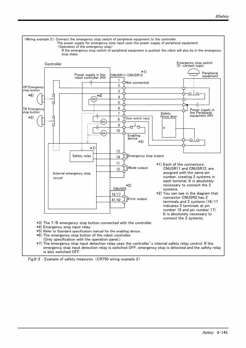
6Safety
Safety 6-145
Fig.6-2 : Example of safety measures (CR750 wiring example 2)
非常停止スイッチ(2接点タイプ)
周辺装置
安全柵のドア
周辺装置側電源24V
CNUSR2
内部非常停止回路
未接続
非常停止出力
モード出力
RA
RA
RA
}
ドアスイッチ入力
イネーブリングデバイス
16/17
41/42 エラー出力}
}
1
CNUSR11/CNUSR12
2
3
4
5
6
7
8
9
10
13
14
11
12
OP非常停止ボタン
TB非常停止ボタン
内部電源 24V
安全リレー
*1) Each of the connectors, CNUSR11 and CNUSR12, are assigned with the same pin number, creating 2 systems in each terminal. It is absolutely necessary to connect the 2 systems.
*2) You can see in the diagram that connector CNUSR2 has 2 terminals and 2 systems (16/17 indicates 2 terminals at pin number 16 and pin number 17). It is absolutely necessary to connect the 2 systems.
<Wiring example 2>: Connect the emergency stop switch of peripheral equipment to the controller. The power supply for emergency stop input uses the power supply of peripheral equipment. <Operation of the emergency stop>
If the emergency stop switch of peripheral equipment is pushed, the robot will also be in the emergency stop state.
Controller
*3) The T/B emergency stop button connected with the controller.*4) Emergency stop input relay.*5) Refer to Standard specification manual for the enabling device.*6) The emergency stop button of the robot controller.
(Only specification with the operation panel.)*7) The emergency stop input detection relay uses the controller’s internal safety relay control. If the
emergency stop input detection relay is switched OFF, emergency stop is detected and the safety relay is also switched OFF.
Power supply in the robot controller 24V
OP Emergency stop button
TB Emergency stop button
Not connected
Door switch input
Enabling device
Mode output
Error output
Emergency stop outputSafety relay
Internal emergency stop circuit
Emergency stop switch (2- contact type)
Peripheral equipment
Safety fence door
Power supply in the Peripheral equipment 24V
*1)
*2)
*3)
*6) *4)
*5)
*7)
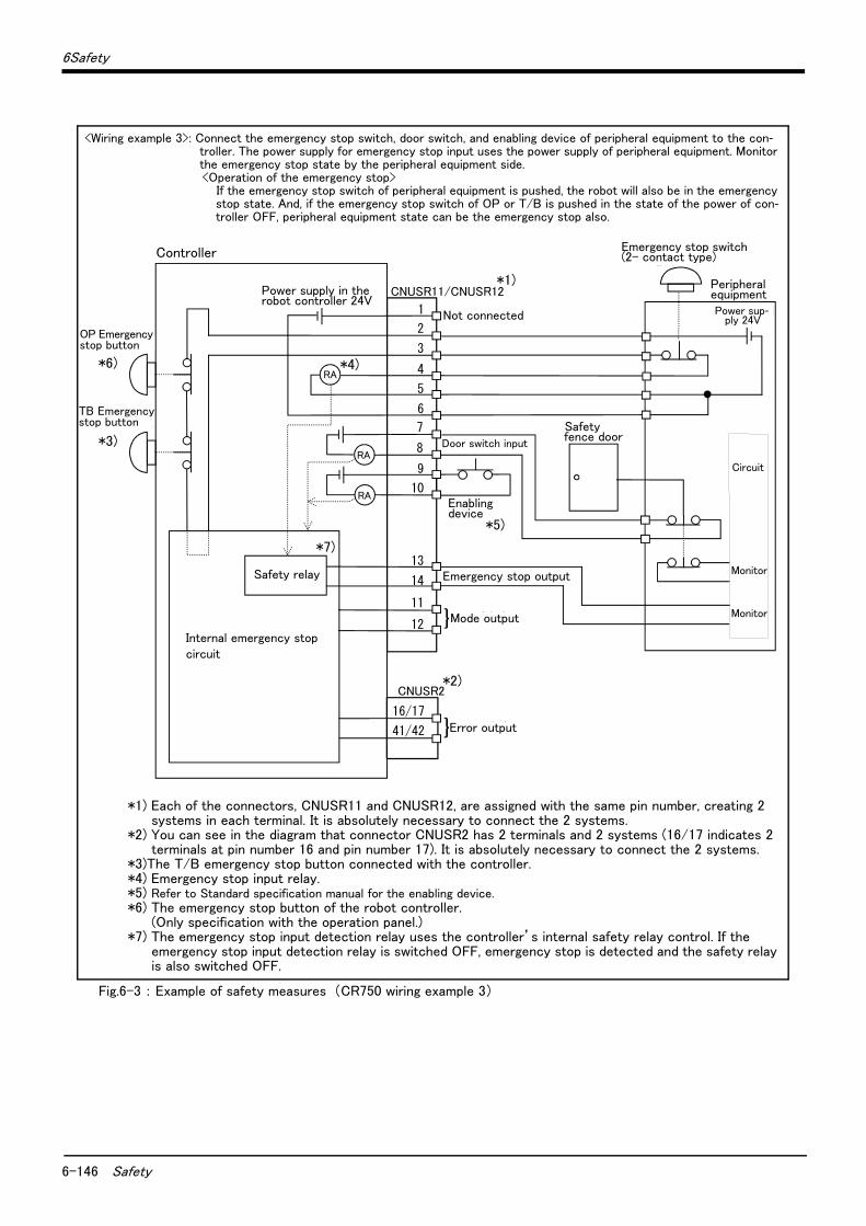
6-146 Safety
6Safety
Fig.6-3 : Example of safety measures (CR750 wiring example 3)
<Wiring example 3>: Connect the emergency stop switch, door switch, and enabling device of peripheral equipment to the con-troller. The power supply for emergency stop input uses the power supply of peripheral equipment. Monitor the emergency stop state by the peripheral equipment side.<Operation of the emergency stop>
If the emergency stop switch of peripheral equipment is pushed, the robot will also be in the emergency stop state. And, if the emergency stop switch of OP or T/B is pushed in the state of the power of con-troller OFF, peripheral equipment state can be the emergency stop also.
非常停止スイッチ(2接点タイプ)
周辺装置
安全柵のドア
周辺装置側電源24V
監視
周 辺 装 置 側 内 部 回 路
CNUSR2
内部非常停止回路
未接続
非常停止出力
モード出力
RA
RA
RA
}
ドアスイッチ入力
イネーブリングデバイス
16/17
41/42 エラー出力}
監視
1
CNUSR11/CNUSR12
2
3
4
5
6
7
8
9
10
13
14
11
12
OP非常停止ボタン
TB非常停止ボタン
内部電源 24V
安全リレー
Controller
*1) Each of the connectors, CNUSR11 and CNUSR12, are assigned with the same pin number, creating 2 systems in each terminal. It is absolutely necessary to connect the 2 systems.
*2) You can see in the diagram that connector CNUSR2 has 2 terminals and 2 systems (16/17 indicates 2 terminals at pin number 16 and pin number 17). It is absolutely necessary to connect the 2 systems.
*3)The T/B emergency stop button connected with the controller.*4) Emergency stop input relay.*5) Refer to Standard specification manual for the enabling device.*6) The emergency stop button of the robot controller.
(Only specification with the operation panel.)*7) The emergency stop input detection relay uses the controller’s internal safety relay control. If the
emergency stop input detection relay is switched OFF, emergency stop is detected and the safety relay is also switched OFF.
Power supply in the robot controller 24V
OP Emergency stop button
TB Emergency stop button
Not connected
Door switch input
Enabling device
Mode output
Error output
Emergency stop outputSafety relay
Internal emergency stop circuit
Emergency stop switch (2- contact type)
Peripheral equipment
Safety fence door
Power sup-ply 24V
*1)
*2)
*3)
*6) *4)
*5)
*7)
Monitor
Monitor
Circuit
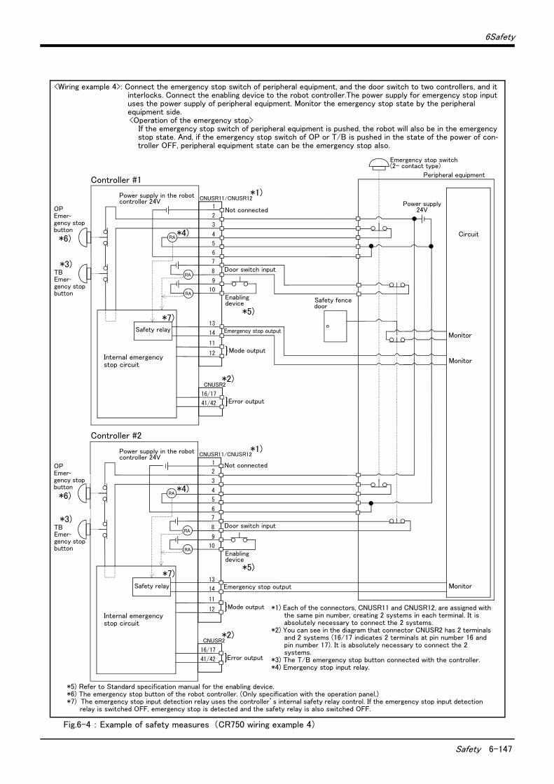
6Safety
Safety 6-147
Fig.6-4 : Example of safety measures (CR750 wiring example 4)
OP非常停止ボタン
TB非常停止ボタン
周辺装置の非常停止出力
周辺装置内部非常停止回路
周辺装置
非常停止スイッチ(4接点タイプ)
安全柵のドア
ドアスイッチ出力
監視
周辺装置の非常停止出力
周辺装置側電源24V
CNUSR2
内部非常停止回路
未接続
非常停止出力
モード出力
RA
RA
RA
}
ドアスイッチ入力
16/17
41/42 エラー出力}
監視
監視
CNUSR2
内部非常停止回路
未接続
非常停止出力
モード出力
RA
RA
RA
}
ドアスイッチ入力
16/17
41/42 エラー出力}
1
CNUSR11/CNUSR12
2
3
4
5
6
7
8
9
10
13
14
11
12
1
CNUSR11/CNUSR12
2
3
4
5
6
7
8
9
10
13
14
11
12
OP非常停止ボタン
TB非常停止ボタン
イネーブリングデバイス
イネーブリングデバイス
内部電源 24V
内部電源 24V
安全リレー
安全リレー
Controller #1
*5) Refer to Standard specification manual for the enabling device.*6) The emergency stop button of the robot controller. (Only specification with the operation panel.)*7) The emergency stop input detection relay uses the controller’s internal safety relay control. If the emergency stop input detection
relay is switched OFF, emergency stop is detected and the safety relay is also switched OFF.
Power supply in the robot controller 24V
OP Emer-gency stop button
TB Emer-gency stop button
Not connected
Enabling device
Mode output
Error output
Emergency stop outputSafety relay
Internal emergency stop circuit
Emergency stop switch (2- contact type)
Peripheral equipment
Safety fence door
Power supply 24V
*1)
*2)
*3)
*6)*4)
*5)*7)
Monitor
Monitor
Circuit
Door switch input
Not connected
<Wiring example 4>: Connect the emergency stop switch of peripheral equipment, and the door switch to two controllers, and it interlocks. Connect the enabling device to the robot controller.The power supply for emergency stop input uses the power supply of peripheral equipment. Monitor the emergency stop state by the peripheral equipment side.<Operation of the emergency stop>
If the emergency stop switch of peripheral equipment is pushed, the robot will also be in the emergency stop state. And, if the emergency stop switch of OP or T/B is pushed in the state of the power of con-troller OFF, peripheral equipment state can be the emergency stop also.
Monitor
Door switch input
Enabling device
Emergency stop output
Power supply in the robot controller 24V
Safety relay
TB Emer-gency stop button
*3)
OP Emer-gency stop button
*6)
Controller #2
*1) Each of the connectors, CNUSR11 and CNUSR12, are assigned with the same pin number, creating 2 systems in each terminal. It is absolutely necessary to connect the 2 systems.
*2) You can see in the diagram that connector CNUSR2 has 2 terminals and 2 systems (16/17 indicates 2 terminals at pin number 16 and pin number 17). It is absolutely necessary to connect the 2 systems.
*3) The T/B emergency stop button connected with the controller.*4) Emergency stop input relay.
Mode output
Error output
Internal emergency stop circuit
*1)
*2)
*7)
*4)
*5)
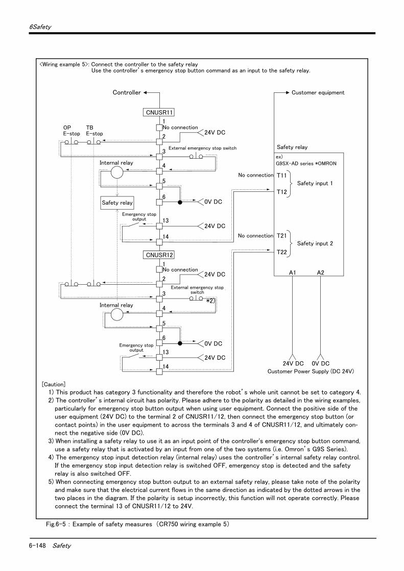
6-148 Safety
6Safety
Fig.6-5 : Example of safety measures (CR750 wiring example 5)
OPE-stop
1
2
3
4
5
6
CNUSR11
内部リレー
TBE-stop
0V DC
1
2
3
4
5
60V DC
内部リレー
T12
T11
T22
T21
No connection
No connection
安全入力1
安全入力2
24V DC 0V DC
例)オムロン社 G9SX-AD
安全リレー
お客様電源(DC 24V)
A1 A2
お客様装置
24V DC
外部非常停止スイッチ
13
14
24V DC
24V DC
外部非常停止スイッチ
13
14
24V DC
安全リレー
非常停止出力
非常停止出力
CNUSR12
No connection
No connection
Controller
Safety relay
*2)
<Wiring example 5>: Connect the controller to the safety relay Use the controller’s emergency stop button command as an input to the safety relay.
Internal relay
Emergency stop output
Internal relay
External emergency stop switch
External emergency stop switch
Emergency stop output
Customer equipment
Safety relay
ex)
G9SX-AD series *OMRON
Safety input 1
Safety input 2
Customer Power Supply (DC 24V)
[Caution]
1) This product has category 3 functionality and therefore the robot’s whole unit cannot be set to category 4.2) The controller’s internal circuit has polarity. Please adhere to the polarity as detailed in the wiring examples,
particularly for emergency stop button output when using user equipment. Connect the positive side of the user equipment (24V DC) to the terminal 2 of CNUSR11/12, then connect the emergency stop button (or contact points) in the user equipment to across the terminals 3 and 4 of CNUSR11/12, and ultimately con-nect the negative side (0V DC).
3) When installing a safety relay to use it as an input point of the controller's emergency stop button command, use a safety relay that is activated by an input from one of the two systems (i.e. Omron’s G9S Series).
4) The emergency stop input detection relay (internal relay) uses the controller’s internal safety relay control. If the emergency stop input detection relay is switched OFF, emergency stop is detected and the safety relay is also switched OFF.
5) When connecting emergency stop button output to an external safety relay, please take note of the polarity and make sure that the electrical current flows in the same direction as indicated by the dotted arrows in the two places in the diagram. If the polarity is setup incorrectly, this function will not operate correctly. Please connect the terminal 13 of CNUSR11/12 to 24V.
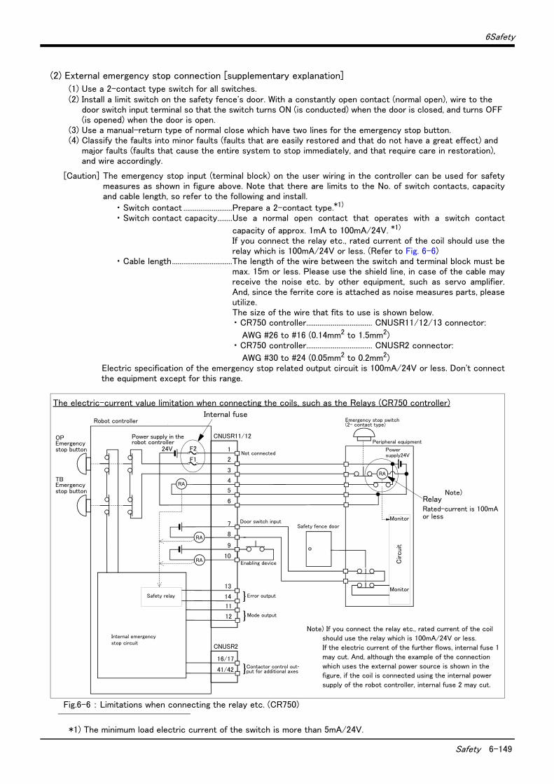
6Safety
Safety 6-149
(2) External emergency stop connection [supplementary explanation]
(1) Use a 2-contact type switch for all switches.(2) Install a limit switch on the safety fence's door. With a constantly open contact (normal open), wire to the
door switch input terminal so that the switch turns ON (is conducted) when the door is closed, and turns OFF (is opened) when the door is open.
(3) Use a manual-return type of normal close which have two lines for the emergency stop button.(4) Classify the faults into minor faults (faults that are easily restored and that do not have a great effect) and
major faults (faults that cause the entire system to stop immediately, and that require care in restoration), and wire accordingly.
[Caution] The emergency stop input (terminal block) on the user wiring in the controller can be used for safetymeasures as shown in figure above. Note that there are limits to the No. of switch contacts, capacityand cable length, so refer to the following and install.
・ Switch contact ..........................Prepare a 2-contact type.*1)
・ Switch contact capacity........Use a normal open contact that operates with a switch contact
capacity of approx. 1mA to 100mA/24V. *1)
If you connect the relay etc., rated current of the coil should use therelay which is 100mA/24V or less. (Refer to Fig. 6-6)
・ Cable length................................The length of the wire between the switch and terminal block must bemax. 15m or less. Please use the shield line, in case of the cable mayreceive the noise etc. by other equipment, such as servo amplifier.And, since the ferrite core is attached as noise measures parts, pleaseutilize.The size of the wire that fits to use is shown below.・ CR750 controller................................... CNUSR11/12/13 connector:
AWG #26 to #16 (0.14mm2 to 1.5mm2)・ CR750 controller................................... CNUSR2 connector:
AWG #30 to #24 (0.05mm2 to 0.2mm2)Electric specification of the emergency stop related output circuit is 100mA/24V or less. Don't connectthe equipment except for this range.
Fig.6-6 : Limitations when connecting the relay etc. (CR750)
*1) The minimum load electric current of the switch is more than 5mA/24V.
1
2
3
4
5
6
13
14
11
12
16/17
41/42
CNUSR11/12
CNUSR2
付加軸用コンタクタコントロール出力
内部非常停止回路
ロボットコントローラ
未接続
非常停止スイッチ(2接点タイプ)
エラー出力
モード出力
周辺装置
TB非常停止ボタン
OP非常停止ボタン
}
RA
RA
RA
}
}
ロボットコントローラ内電源 24V
ドアスイッチ入力安全柵のドア
イネーブリングデバイス
周辺装置側電源24V
監視
監視
周 辺 装 置 側 内 部 回 路
RA
安全リレー
7
8
9
10
F2
F1
The electric-current value limitation when connecting the coils, such as the Relays (CR750 controller)
RelayRated-current is 100mA or less
Note) If you connect the relay etc., rated current of the coil
should use the relay which is 100mA/24V or less.
If the electric current of the further flows, internal fuse 1
may cut. And, although the example of the connection
which uses the external power source is shown in the
figure, if the coil is connected using the internal power
supply of the robot controller, internal fuse 2 may cut.
Internal fuse
Not connected
Door switch inputSafety fence door
Enabling device
Error output
Mode output
Power supply in the robot controller
Robot controller
OPEmergency stop button
TBEmergency stop button
Safety relay
Internal emergency stop circuit
Emergency stop switch(2- contact type)
Peripheral equipment
Power supply24V
Contactor control out-put for additional axes
Monitor
Monitor
Circuit
Note)
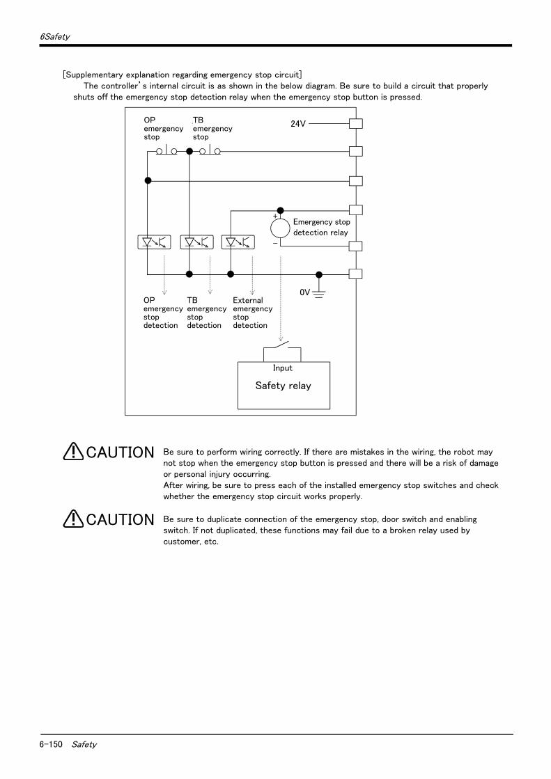
6-150 Safety
6Safety
[Supplementary explanation regarding emergency stop circuit]The controller’s internal circuit is as shown in the below diagram. Be sure to build a circuit that properly
shuts off the emergency stop detection relay when the emergency stop button is pressed.
Be sure to perform wiring correctly. If there are mistakes in the wiring, the robot may not stop when the emergency stop button is pressed and there will be a risk of damage or personal injury occurring.After wiring, be sure to press each of the installed emergency stop switches and check whether the emergency stop circuit works properly.
Be sure to duplicate connection of the emergency stop, door switch and enabling switch. If not duplicated, these functions may fail due to a broken relay used by customer, etc.
OP非常停止
非常停止検出リレー
24VTB非常停止
+
-
OP非常停止検出
TB非常停止検出
外部非常停止検出
0V
入力
安全リレーSafety relay
Input
Emergency stop detection relay
TB emergency stop
OP emergency stop
OP emergency stop detection
TB emergency stop detection
External emergency stop detection
CAUTION
CAUTION

6Safety
Working environment 6-151
6.2 Working environment
Avoid installation in the following places as the equipment's life and operation will be affected by the ambient environment conditions. When using in the following conditions, the customer must pay special attention to the preventive measures.
(1) Power supply・ Where the voltage fluctuation will exceed the input voltage range.・ Where a momentary power failure exceeding 20ms may occur.・ Where the power capacity cannot be sufficiently secured.
Please use the controller with an input power supply voltage fluctuation rate of 10% or less. In the case of 200 VAC input, for example, if the controller is used with 180 VAC during the day and 220 VAC during the night, turn the servo off once and then on again.
If this is not performed, an excessive regeneration error may occur.
(2) Noise・ Where a surge voltage exceeding 1000V, 1μs may be applied on the primary voltage. Near large inverters, highoutput frequency oscillator, large contactors and welding machines. Static noise may enter the lines when thisproduct is used near radios or televisions. Keep the robot away from these items.
(3) Temperature and humidity・ Where the atmospheric temperature exceeds 40 degree , lower than 0 degree.・ Where the relative humidity exceeds 85%, lower than 45%, and where dew may condense.・ Where the robot will be subject to direct sunlight or near heat generating sources such as heaters.
(4) Vibration・ Where excessive vibration or impact may be applied. (Use in an environment of 34m/s2 or less during transpor-tation and 5m/s2 or less during operation.)
(5) Installation environment・ Where strong electric fields or magnetic fields are generated.・ Where the installation surface is rough. (Avoid installing the robot on a bumpy or inclined floor.)・ Where there is heavy powder dust and oil mist present.
6.3 Precautions for handling(1) This robot has brakes on all axes. The precision of the robot may drop, looseness may occur and the reduction
gears may be damaged if the robot is moved with force with the brakes applied.(2) Avoid moving the robot arm by hand. When unavoidable, gradually move the arm. If moved suddenly, the accu-
racy may drop due to an excessive backlash, or the backed up data may be destroyed.(3) Note that depending on the posture, even when within the movement range, the wrist section could interfere
with the base section. Take care to prevent interference during jog. *1)
(4) The robot arm consists of precision parts such as bearing. Lubricants such as grease are also applied on the moving parts to keep the mechanical accuracy. In a cold start under low temperature or in the first start after being stored for one month or longer, lubricants may not be spread enough. Such condition may lower the posi-tioning accuracy, cause servo and overload alarms, and early wearing of the moving parts. To avoid such situ-ation, perform warm-up operation of the machine at a low speed (at about 20% of normal operation speed). Move the robot arm from the lower to the upper limit of the movable range with the 30 degree joint angle or more for about 10 minutes. After that, speed up the operation gradually. Please use the warm-up operation. (About the details of the warm-up operation, refer to "INSTRUCTION MANUAL/Detailed explanations of functions and operations".)
(5) The robot arm and controller must be grounded with 100Ω or less (class D grounding) to secure the noise resistance and to prevent electric shocks.
*1) Jog operation refers to operating the robot manually using the teaching pendant.
CAUTION
6-152 Precautions for handling
6Safety
(6) The items described in these specifications are conditions for carrying out the periodic maintenance and inspections described in the instruction manual.
(7) When using the robot arm on a mobile axis or elevating table, the machine cables enclosed as standard config-uration may break due to the fixed installation specifications. In this case, use "the machine cable extension (for flexed)" factory shipment special specifications or options.
(8) If this robot interferes with the workpiece or peripheral devices during operation, the position may deviate, etc. Take care to prevent interference with the workpiece or peripheral devices during operation.
(9) The hanging installation jig can be borrowed from the maker. Order to dealer when need.(10) Do not attach a tape or a label to the robot arm and the controller. If a tape or a label with strong adhesive
power, such as a packaging tape, is attached to the coated surfaces of the robot arm and controller, the coated surface may be damaged when such tape or label is peeled off.
(11) If the robot is operated with a heavy load and at a high speed, the surface of the robot arm gets very hot. It would not result in burns, however, it may cause secondary accidents if touched carelessly.
(12) Do not shut down the input power supply to stop the robot. If the power supply is frequently shut down during a heavy load or high-speed operation, the speed reducer may be damaged, backlash may occur, and the pro-gram data may be destroyed.
(13) If the J1, J2 and J3 axes collide with the mechanical stopper during the automatic operation of the robot, it is necessary to replace the resin part of the mechanical stopper unit. For the replacement of the resin parts, please contact Mitsubishi or Mitsubishi's dealer. If the resin part is not replaced, the mechanism unit and the speed reducer may be damaged significantly when the axes collide with the mechanical stopper next or subsequent time.
(14) During the robot's automatic operation, a break is applied to the robot arm when the input power supply is shut down by a power failure, for instance. When a break is applied, the arm may deviate from the operation path predetermined by automatic operation and, as a result, it may interfere with the mechanical stopper depending on the operation at shutdown. In such a case, take an appropriate measure in advance to prevent any dangerous situation from occurring due to the interference between the arm and peripheral devices.Example) Installing a UPS (uninterruptible power supply unit) to the primary power source in order to reduce
interference.
(15) The J1 to J3 axes of the RV-13F series generate loud noise during high-speed operation because of their reduction gear structure, but it does not affect the robot's function, performance, and a life.
(16) Do not conduct an insulated voltage test. If conducted by mistake, it may result in a breakdown.(17) Fretting may occur on the axis which moving angle or moving distance move minutely, or not moves. Fretting
is that the required oil film becomes hard to be formed if the moving angle is small, and wear occurs. The axis which not moved is moving slightly by vibration etc. To make no fretting recommends to move these axes about once every day the 30 degree or more, or the 20mm or more.
(18) The United Nations’ Recommendations on the Transport of Dangerous Goods must be observed for trans-border transportation of lithium batteries by air, sea, and land. The lithium batteries (ER6, Q6BAT) used in Mit-subishi industrial robots contain less than 1 g of lithium and are not classified as dangerous goods. However, if the quantity of lithium batteries exceeds 24 batteries for storage, etc., they will be classified as Class 9: Mis-cellaneous dangerous substances and articles. Shipping less than 24 batteries is recommended to avoid having to carry out transport safety measures as the customer’s consignor. Note that some transportation compa-nies may request an indication that the batteries are not dangerous goods be included on the invoice. For ship-ping requirement details, please contact your transportation company.
(19) If the air supply temperature (primary piping) used for the tool etc. is lower than ambient air temperature, the dew condensation may occur on the coupling or the hose surface.
(20) When fumigants that contain halogen materials such as fluorine, chlorine, bromine, and iodine are used for dis-infecting and protecting wooden packaging from insects, they cause malfunction when entering our products. Please take necessary precautions to ensure that remaining materials from fumigant do not enter our prod-ucts, or treat packaging with methods other than fumigation (heat method). Additionally, disinfect and protect wood from insects before packing products.

6Safety
EMC installation guideline 6-153
6.4 EMC installation guideline
6.4.1 OutlinesThe EMC directive is coerced from January 1, 1996, and it is necessary to attach the CE mark which shows that the product is in conformity to directive.
Since the industrial robot is the component of the automation system, it considers that the EMC directive is not the target product of the direct. However, because it is one of the main components, introduces the method and components of the measures for conforming the automation system to the EMC directive.
And also we are carrying out the qualification test about the conformity of the EMC directive under the environ-ment based on the contents of this document. However, the noise level is changed by the kind of equipment to be used, the layout, the construction of the controlling board, the course of wiring, etc. Therefore, please confirm by the customer eventually.
6.4.2 EMC directiveThe Mitsubishi Electric industrial robot follows the European EMC directive. This technical standard regulates the following two items.
(1) Emission (EMI : Electromagnetic Interference) ..............The capacity not to generate the disturbance noise which has a bad influence outside.
(2) Immunity (EMS : Electromagnetic Susceptibility)..........The capacity which does not malfunction for the dis-turbance noise from the outside.
Each contents are shown below.
Item Name ContentsTesting technical-
standard number
Emission
(EMI)
Radiative noise disturbance The electromagnetic noise etc. which are emitted to
environs.
EN61000-6-2 : 2005
EN61000-6-4 : 2007
EN62061:2005(Annex E)Electrical-conduction noise disturbance The electromagnetism noise etc. which flow out of
the power-supply line.
Immunity
(EMS)
Electrostatic discharge immunity test The noise from the electrified human body.
Radiated, radio-frequency, electromagnetic
field immunity test susceptibility test
The electromagnetism noise from the transceiver,
the broadcasting station, etc.
Electrical fast transient burst immunity
test
The relay noise or the electromagnetism noise etc.
which are caused in power-supply ON/OFF.
Immunity to conducted distrurbances
induced radio-frequency fields
The electromagnetism noise etc. which flow in
through the power source wire and the grounding
wire.
Power frequency magnetic field immunity
test
The electromagnetism noise with a power supply
frequency of 50/60 Hz etc.
Voltage dips, short interruptions and
voltage variations immunity test
The noise in the variation of the source voltage of
the power dispatching, etc.
Surge immunity test The electromagnetism noise by the thunderbolt, etc.
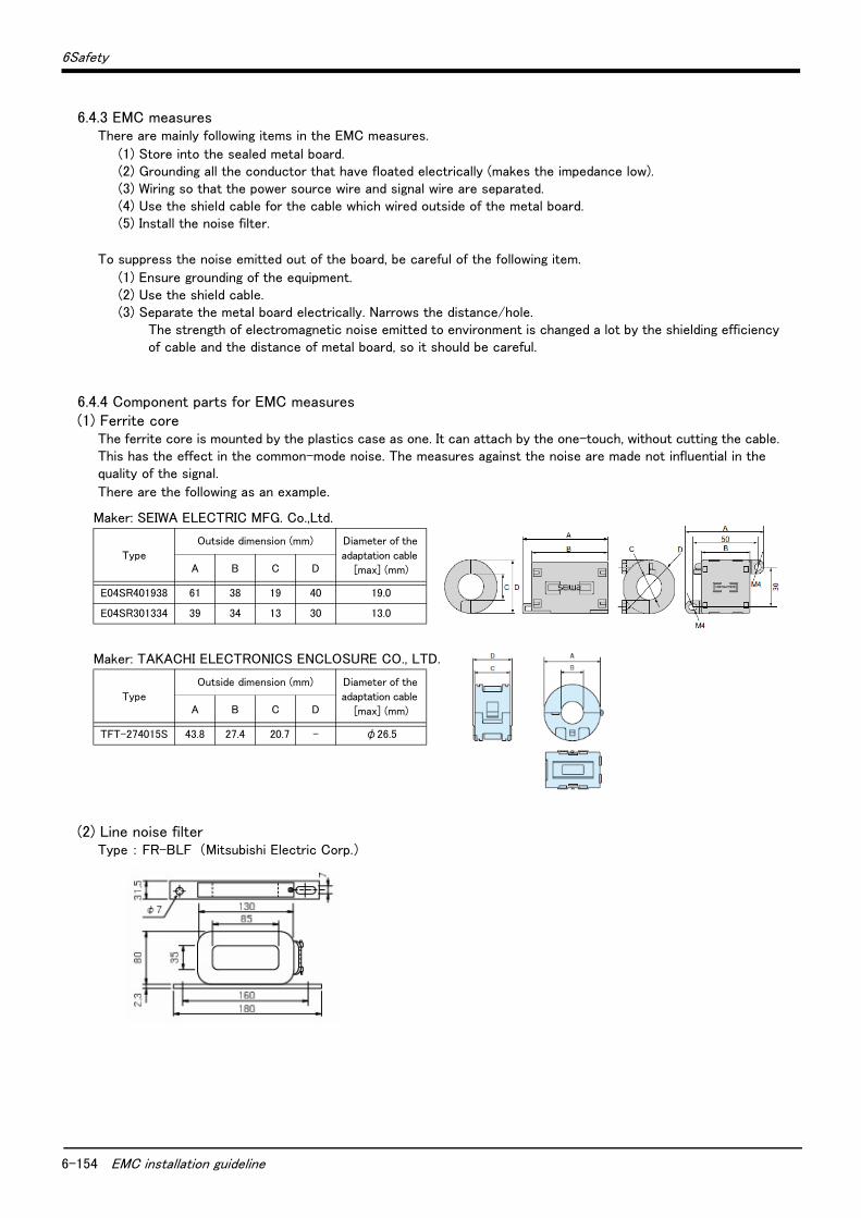
6-154 EMC installation guideline
6Safety
6.4.3 EMC measuresThere are mainly following items in the EMC measures.
(1) Store into the sealed metal board.(2) Grounding all the conductor that have floated electrically (makes the impedance low).(3) Wiring so that the power source wire and signal wire are separated.(4) Use the shield cable for the cable which wired outside of the metal board.(5) Install the noise filter.
To suppress the noise emitted out of the board, be careful of the following item.
(1) Ensure grounding of the equipment.(2) Use the shield cable.(3) Separate the metal board electrically. Narrows the distance/hole.
The strength of electromagnetic noise emitted to environment is changed a lot by the shielding efficiency of cable and the distance of metal board, so it should be careful.
6.4.4 Component parts for EMC measures(1) Ferrite core
The ferrite core is mounted by the plastics case as one. It can attach by the one-touch, without cutting the cable. This has the effect in the common-mode noise. The measures against the noise are made not influential in the quality of the signal.
There are the following as an example.
(2) Line noise filterType : FR-BLF (Mitsubishi Electric Corp.)
Maker: SEIWA ELECTRIC MFG. Co.,Ltd.
Type
Outside dimension (mm) Diameter of the
adaptation cable
[max] (mm)A B C D
E04SR401938 61 38 19 40 19.0
E04SR301334 39 34 13 30 13.0
Maker: TAKACHI ELECTRONICS ENCLOSURE CO., LTD.
Type
Outside dimension (mm) Diameter of the
adaptation cable
[max] (mm)A B C D
TFT-274015S 43.8 27.4 20.7 - φ26.5
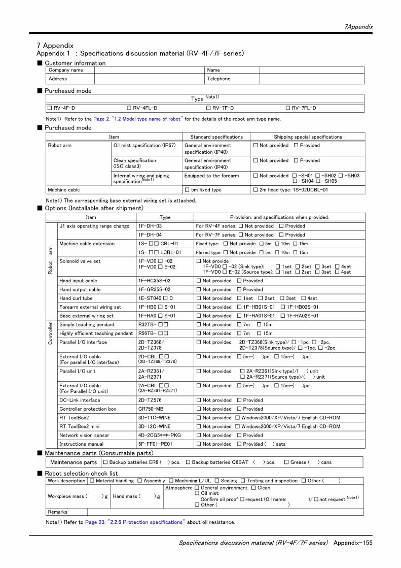
7Appendix
Specifications discussion material (RV-4F/7F series) Appendix-155
7 AppendixAppendix 1 : Specifications discussion material (RV-4F/7F series)
■ Customer information
■ Purchased mode
■ Purchased mode
■ Options (Installable after shipment)
■ Maintenance parts (Consumable parts)
■ Robot selection check list
Company name Name
Address Telephone
Type Note1)
Note1) Refer to the Page 2, "1.2 Model type name of robot" for the details of the robot arm type name.
□ RV-4F-D □ RV-4FL-D □ RV-7F-D □ RV-7FL-D
Item Standard specifications Shipping special specifications
Robot arm Oil mist specification (IP67) General environment
specification (IP40)
□ Not provided □ Provided
Clean specification (ISO class3)
General environment
specification (IP40)
□ Not provided □ Provided
Internal wiring and piping specificationNote1)
Note1) The corresponding base external wiring set is attached.
Equipped to the forearm □ Not provided □ -SH01 □ -SH02 □ -SH03□ -SH04 □ -SH05
Machine cable □ 5m fixed type □ 2m fixed type: 1S-02UCBL-01
Item Type Provision, and specifications when provided.
J1 axis operating range change 1F-DH-03 For RV-4F series: □ Not provided □ Provided
1F-DH-04 For RV-7F series: □ Not provided □ Provided
arm
Machine cable extension 1S- □□ CBL-01 Fixed type: □ Not provide □ 5m □ 10m □ 15m
1S- □□ LCBL-01 Flexed type: □ Not provide □ 5m □ 10m □ 15m
Robo
t Solenoid valve set 1F-VD0 □ -021F-VD0 □ E-02
□ Not provide1F-VD0 □ -02 (Sink type): □ 1set □ 2set □ 3set □ 4set1F-VD0 □ E-02 (Source type): □ 1set □ 2set □ 3set □ 4set
Hand input cable 1F-HC35S-02 □ Not provided □ Provided
Hand output cable 1F-GR35S-02 □ Not provided □ Provided
Hand curl tube 1E-ST040 □ C □ Not provided □ 1set □ 2set □ 3set □ 4set
Forearm external wiring set 1F-HB0 □ S-01 □ Not provided □ 1F-HB01S-01 □ 1F-HB02S-01
Base external wiring set 1F-HA0 □ S-01 □ Not provided □ 1F-HA01S-01 □ 1F-HA02S-01
Contr
olle
r Simple teaching pendant R32TB- □□ □ Not provided □ 7m □ 15m
Highly efficient teaching pendant R56TB- □□ □ Not provided □ 7m □ 15m
Parallel I/O interface 2D-TZ368/2D-TZ378
□ Not provided 2D-TZ368(Sink type)/ □ -1pc. □ -2pc.2D-TZ378(Source type)/ □ -1pc. □ -2pc.
External I/O cable(For parallel I/O interface)
2D-CBL □□(2D-TZ368/TZ378)
□ Not provided □ 5m-( )pc. □ 15m-( )pc.
Parallel I/O unit 2A-RZ361/2A-RZ371
□ Not provided □ 2A-RZ361(Sink type)/( ) unit□ 2A-RZ371(Source type)/( ) unit
External I/O cable(For Parallel I/O unit)
2A-CBL □□(2A-RZ361/RZ371)
□ Not provided □ 5m-( )pc. □ 15m-( )pc.
CC-Link interface 2D-TZ576 □ Not provided □ Provided
Controller protection box CR750-MB □ Not provided □ Provided
RT ToolBox2 3D-11C-WINE □ Not provided □ Windows2000/XP/Vista/7 English CD-ROM
RT ToolBox2 mini 3D-12C-WINE □ Not provided □ Windows2000/XP/Vista/7 English CD-ROM
Network vision sensor 4D-2CG5***-PKG □ Not provided □ Provided
Instructions manual 5F-FF01-PE01 □ Not provided □ Provided ( ) sets
Maintenance parts □ Backup batteries ER6 ( ) pcs. □ Backup batteries Q6BAT ( ) pcs. □ Grease ( ) cans
Work description □ Material handling □ Assembly □ Machining L/UL □ Sealing □ Testing and inspection □ Other ( )
Workpiece mass ( ) g Hand mass ( ) g
Atmosphere □ General environment □ Clean□ Oil mist:
Confirm oil proof □request (Oil name: )/□not request Note1) □ Other ( )
Note1) Refer to Page 23, "2.2.6 Protection specifications" about oil resistance.
Remarks

Appendix-156 Specifications discussion material (RV-7FLL)
7Appendix
Appendix 2 : Specifications discussion material (RV-7FLL)
■ Customer information
■ Purchased mode
■ Purchased mode
■ Options (Installable after shipment)
■ Maintenance parts (Consumable parts)
■ Robot selection check list
Company name Name
Address Telephone
Type Note1)
Note1) Refer to the Page 2, "1.2 Model type name of robot" for the details of the robot arm type name.
■ RV-7FLL-D (General environment specification (IP40))
Item Standard specifications Shipping special specifications
Robot arm Internal wiring and piping specificationNote1)
Note1) The corresponding base external wiring set is attached.
Equipped to the forearm □ Not provided □ -SH01 □ -SH02 □ -SH03□ -SH04 □ -SH05
Machine cable □ 7m fixed type □ 2m fixed type: 1S-02UCBL-01
Item Type Provision, and specifications when provided.
J1 axis operating range change 1F-DH-05J1 □ Not provided □ Provided
arm
Machine cable extension 1S- □□ CBL-01 Fixed type: □ Not provide □ 5m □ 10m □ 15m
1S- □□ LCBL-01 Flexed type: □ Not provide □ 5m □ 10m □ 15m
Robot Solenoid valve set 1F-VD0 □ -02
1F-VD0 □ E-02□ Not provide
1F-VD0 □ -02 (Sink type): □ 1set □ 2set □ 3set □ 4set1F-VD0 □ E-02 (Source type): □ 1set □ 2set □ 3set □ 4set
Hand input cable 1F-HC35S-02 □ Not provided □ Provided
Hand output cable 1F-GR35S-02 □ Not provided □ Provided
Hand curl tube 1E-ST040 □ C □ Not provided □ 1set □ 2set □ 3set □ 4set
Forearm external wiring set 1F-HB0 □ S-01 □ Not provided □ 1F-HB01S-01 □ 1F-HB02S-01
Base external wiring set 1F-HA0 □ S-01 □ Not provided □ 1F-HA01S-01 □ 1F-HA02S-01
Contr
olle
r Simple teaching pendant R32TB- □□ □ Not provided □ 7m □ 15m
Highly efficient teaching pendant R56TB- □□ □ Not provided □ 7m □ 15m
Parallel I/O interface 2D-TZ368/2D-TZ378
□ Not provided 2D-TZ368(Sink type)/ □ -1pc. □ -2pc.2D-TZ378(Source type)/ □ -1pc. □ -2pc.
External I/O cable(For parallel I/O interface)
2D-CBL □□(2D-TZ368/TZ378)
□ Not provided □ 5m-( )pc. □ 15m-( )pc.
Parallel I/O unit 2A-RZ361/2A-RZ371
□ Not provided □ 2A-RZ361(Sink type)/( ) unit□ 2A-RZ371(Source type)/( ) unit
External I/O cable(For Parallel I/O unit)
2A-CBL □□(2A-RZ361/RZ371)
□ Not provided □ 5m-( )pc. □ 15m-( )pc.
CC-Link interface 2D-TZ576 □ Not provided □ Provided
Controller protection box CR750-MB □ Not provided □ Provided
RT ToolBox2 3D-11C-WINE □ Not provided □ Windows2000/XP/Vista/7 English CD-ROM
RT ToolBox2 mini 3D-12C-WINE □ Not provided □ Windows2000/XP/Vista/7 English CD-ROM
Network vision sensor 4D-2CG5***-PKG □ Not provided □ Provided
Instructions manual 5F-FF01-PE01 □ Not provided □ Provided ( ) sets
Maintenance parts □ Backup batteries ER6 ( ) pcs. □ Backup batteries Q6BAT ( ) pcs. □ Grease ( ) cans
Work description □ Material handling □ Assembly □ Machining L/UL □ Sealing □ Testing and inspection □ Other ( )
Workpiece mass ( ) g Hand mass ( ) g Atmosphere □ General environment□ Other ( )
Remarks

7Appendix
Specifications discussion material (RV-13F/13FL) Appendix-157
Appendix 3 : Specifications discussion material (RV-13F/13FL)
■ Customer information
■ Purchased mode
■ Purchased mode
■ Options (Installable after shipment)
■ Maintenance parts (Consumable parts)
■ Robot selection check list
Company name Name
Address Telephone
Type Note1)
Note1) Refer to the Page 2, "1.2 Model type name of robot" for the details of the robot arm type name.
□ RV-13F-D □ RV-13FL-D
Item Standard specifications Shipping special specifications
Robot arm Oil mist specification (IP67) General environment specification (IP40)
□ Not provided □ Provided
Clean specification (ISO class3)
General environment specification (IP40)
□ Not provided □ Provided
Internal wiring and piping specificationNote1)
Note1) The corresponding base external wiring set is attached.
Equipped to the forearm □ Not provided □ -SH01 □ -SH02 □ -SH03□ -SH04 □ -SH05
Machine cable □ 7m fixed type □ 2m fixed type: 1S-02UCBL-01
Item Type Provision, and specifications when provided.
J1 axis operating range change 1F-DH-05J1 □ Not provided □ Provided
arm
Machine cable extension 1S- □□ CBL-01 Fixed type: □ Not provide □ 5m □ 10m □ 15m
1S- □□ LCBL-01 Flexed type: □ Not provide □ 5m □ 10m □ 15m
Robo
t Solenoid valve set 1F-VD0 □ -031F-VD0 □ E-03
□ Not provide1F-VD0 □ -03 (Sink type): □ 1set □ 2set □ 3set □ 4set1F-VD0 □ E-03 (Source type): □ 1set □ 2set □ 3set □ 4set
Hand input cable 1F-HC35S-02 □ Not provided □ Provided
Hand output cable 1F-GR35S-02 □ Not provided □ Provided
Hand curl tube 1N-ST060 □ C □ Not provided □ 1set □ 2set □ 3set □ 4set
Forearm external wiring set 1F-HB0 □ S-01 □ Not provided □ 1F-HB01S-01 □ 1F-HB02S-01
Base external wiring set 1F-HA0 □ S-01 □ Not provided □ 1F-HA01S-01 □ 1F-HA02S-01
Cont
rolle
r Simple teaching pendant R32TB- □□ □ Not provided □ 7m □ 15m
Highly efficient teaching pendant R56TB- □□ □ Not provided □ 7m □ 15m
Parallel I/O interface 2D-TZ368/2D-TZ378
□ Not provided 2D-TZ368(Sink type)/ □ -1pc. □ -2pc.2D-TZ378(Source type)/ □ -1pc. □ -2pc.
External I/O cable(For parallel I/O interface)
2D-CBL □□(2D-TZ368/TZ378)
□ Not provided □ 5m-( )pc. □ 15m-( )pc.
Parallel I/O unit 2A-RZ361/2A-RZ371
□ Not provided □ 2A-RZ361(Sink type)/( ) unit□ 2A-RZ371(Source type)/( ) unit
External I/O cable(For Parallel I/O unit)
2A-CBL □□(2A-RZ361/RZ371)
□ Not provided □ 5m-( )pc. □ 15m-( )pc.
CC-Link interface 2D-TZ576 □ Not provided □ Provided
Controller protection box CR750-MB □ Not provided □ Provided
RT ToolBox2 3D-11C-WINE □ Not provided □ Windows2000/XP/Vista/7 English CD-ROM
RT ToolBox2 mini 3D-12C-WINE □ Not provided □ Windows2000/XP/Vista/7 English CD-ROM
Network vision sensor 4D-2CG5***-PKG □ Not provided □ Provided
Instructions manual 5F-FF01-PE01 □ Not provided □ Provided ( ) sets
Maintenance parts □ Backup batteries ER6 ( ) pcs. □ Backup batteries Q6BAT ( ) pcs. □ Grease ( ) cans
Work description □ Material handling □ Assembly □ Machining L/UL □ Sealing □ Testing and inspection □ Other ( )
Workpiece mass ( ) g Hand mass ( ) g
Atmosphere □ General environment □ Clean□ Oil mist:
Confirm oil proof □request (Oil name: )/□not request Note1) □ Other ( )
Note1) Refer to Page 23, "2.2.6 Protection specifications" about oil resistance.
Remarks
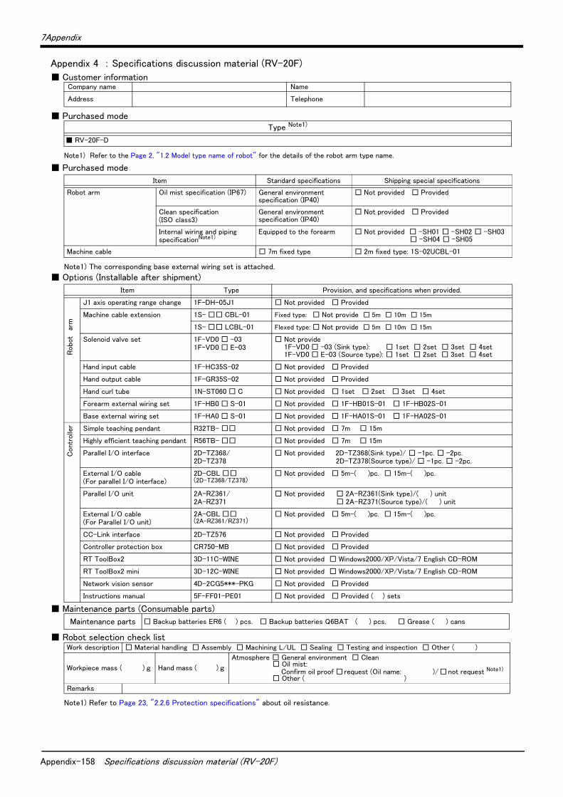
Appendix-158 Specifications discussion material (RV-20F)
7Appendix
Appendix 4 : Specifications discussion material (RV-20F)
■ Customer information
■ Purchased mode
■ Purchased mode
■ Options (Installable after shipment)
■ Maintenance parts (Consumable parts)
■ Robot selection check list
Company name Name
Address Telephone
Type Note1)
Note1) Refer to the Page 2, "1.2 Model type name of robot" for the details of the robot arm type name.
■ RV-20F-D
Item Standard specifications Shipping special specifications
Robot arm Oil mist specification (IP67) General environment specification (IP40)
□ Not provided □ Provided
Clean specification (ISO class3)
General environment specification (IP40)
□ Not provided □ Provided
Internal wiring and piping specificationNote1)
Note1) The corresponding base external wiring set is attached.
Equipped to the forearm □ Not provided □ -SH01 □ -SH02 □ -SH03□ -SH04 □ -SH05
Machine cable □ 7m fixed type □ 2m fixed type: 1S-02UCBL-01
Item Type Provision, and specifications when provided.
J1 axis operating range change 1F-DH-05J1 □ Not provided □ Provided
arm
Machine cable extension 1S- □□ CBL-01 Fixed type: □ Not provide □ 5m □ 10m □ 15m
1S- □□ LCBL-01 Flexed type: □ Not provide □ 5m □ 10m □ 15m
Robo
t Solenoid valve set 1F-VD0 □ -031F-VD0 □ E-03
□ Not provide1F-VD0 □ -03 (Sink type): □ 1set □ 2set □ 3set □ 4set1F-VD0 □ E-03 (Source type): □ 1set □ 2set □ 3set □ 4set
Hand input cable 1F-HC35S-02 □ Not provided □ Provided
Hand output cable 1F-GR35S-02 □ Not provided □ Provided
Hand curl tube 1N-ST060 □ C □ Not provided □ 1set □ 2set □ 3set □ 4set
Forearm external wiring set 1F-HB0 □ S-01 □ Not provided □ 1F-HB01S-01 □ 1F-HB02S-01
Base external wiring set 1F-HA0 □ S-01 □ Not provided □ 1F-HA01S-01 □ 1F-HA02S-01
Cont
rolle
r Simple teaching pendant R32TB- □□ □ Not provided □ 7m □ 15m
Highly efficient teaching pendant R56TB- □□ □ Not provided □ 7m □ 15m
Parallel I/O interface 2D-TZ368/2D-TZ378
□ Not provided 2D-TZ368(Sink type)/ □ -1pc. □ -2pc.2D-TZ378(Source type)/ □ -1pc. □ -2pc.
External I/O cable(For parallel I/O interface)
2D-CBL □□(2D-TZ368/TZ378)
□ Not provided □ 5m-( )pc. □ 15m-( )pc.
Parallel I/O unit 2A-RZ361/2A-RZ371
□ Not provided □ 2A-RZ361(Sink type)/( ) unit□ 2A-RZ371(Source type)/( ) unit
External I/O cable(For Parallel I/O unit)
2A-CBL □□(2A-RZ361/RZ371)
□ Not provided □ 5m-( )pc. □ 15m-( )pc.
CC-Link interface 2D-TZ576 □ Not provided □ Provided
Controller protection box CR750-MB □ Not provided □ Provided
RT ToolBox2 3D-11C-WINE □ Not provided □ Windows2000/XP/Vista/7 English CD-ROM
RT ToolBox2 mini 3D-12C-WINE □ Not provided □ Windows2000/XP/Vista/7 English CD-ROM
Network vision sensor 4D-2CG5***-PKG □ Not provided □ Provided
Instructions manual 5F-FF01-PE01 □ Not provided □ Provided ( ) sets
Maintenance parts □ Backup batteries ER6 ( ) pcs. □ Backup batteries Q6BAT ( ) pcs. □ Grease ( ) cans
Work description □ Material handling □ Assembly □ Machining L/UL □ Sealing □ Testing and inspection □ Other ( )
Workpiece mass ( ) g Hand mass ( ) g
Atmosphere □ General environment □ Clean□ Oil mist:
Confirm oil proof □request (Oil name: )/□not request Note1) □ Other ( )
Note1) Refer to Page 23, "2.2.6 Protection specifications" about oil resistance.
Remarks
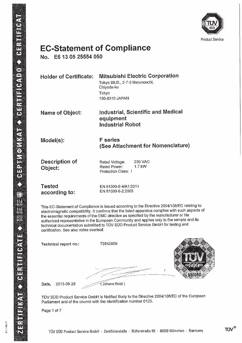
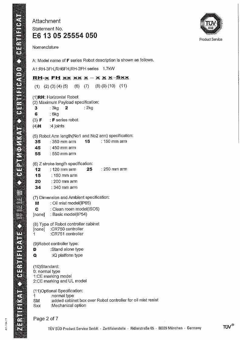

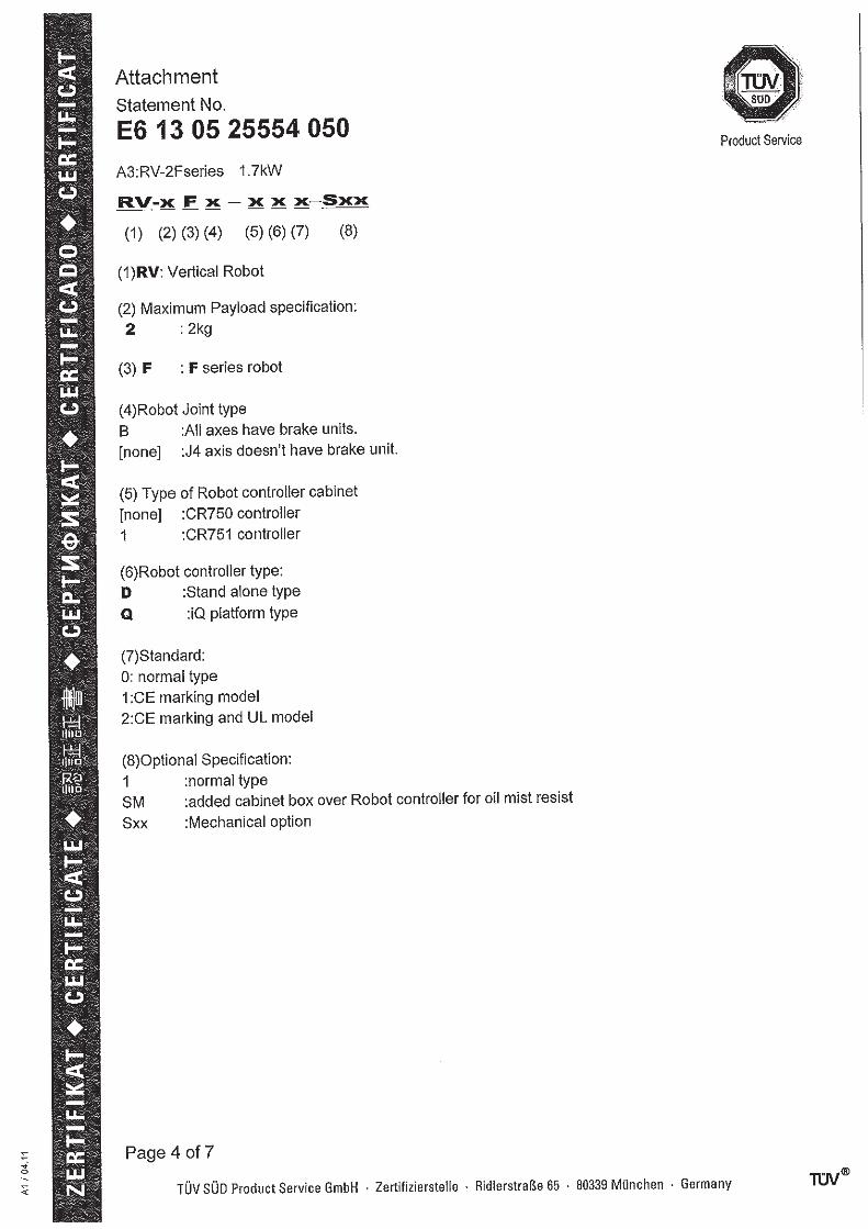

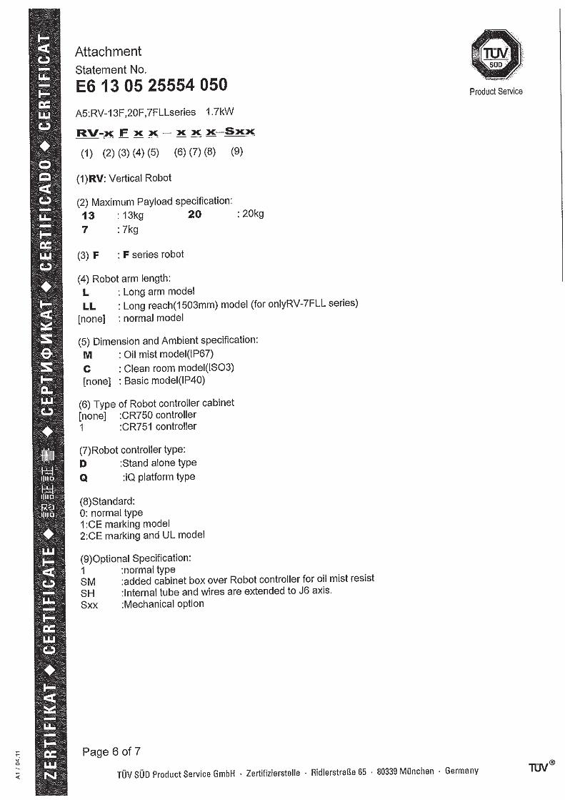
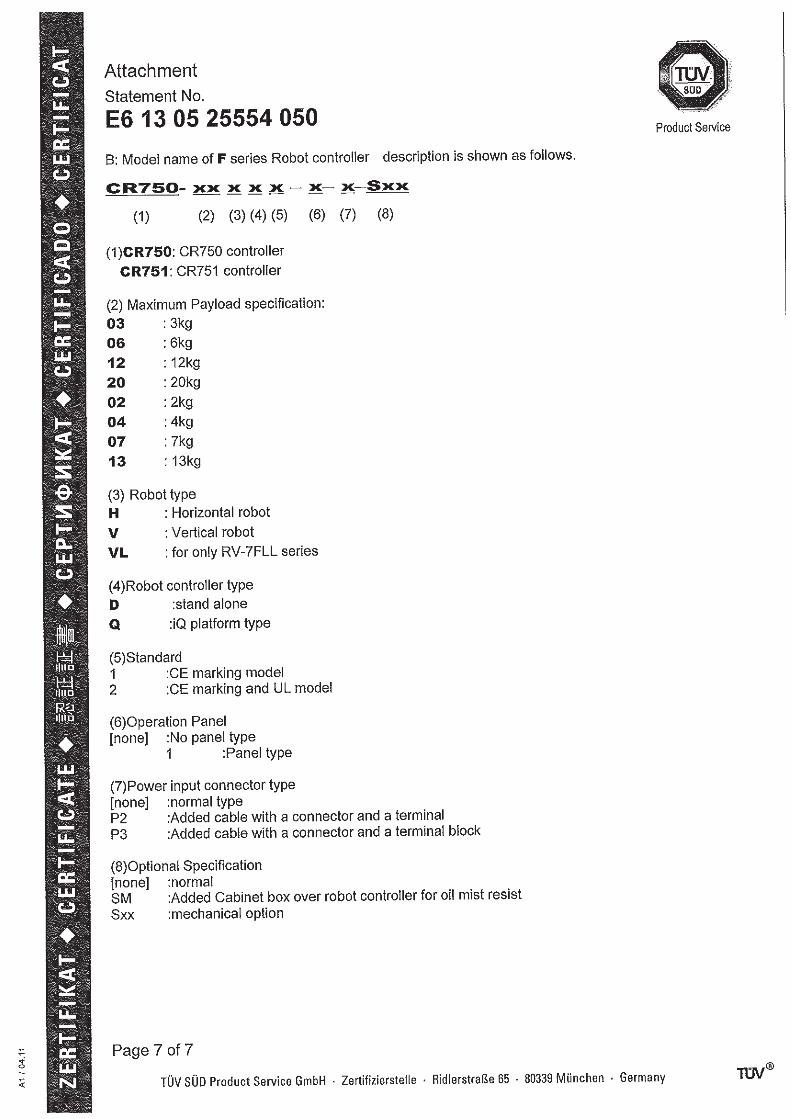
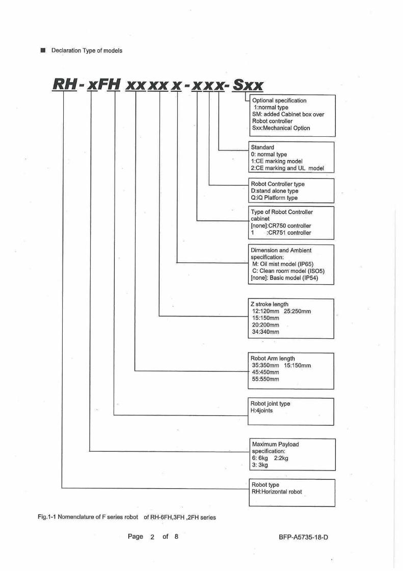

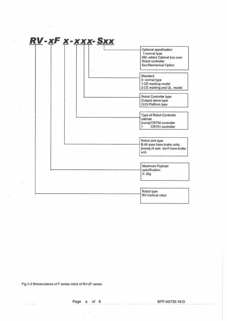
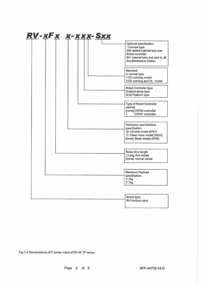

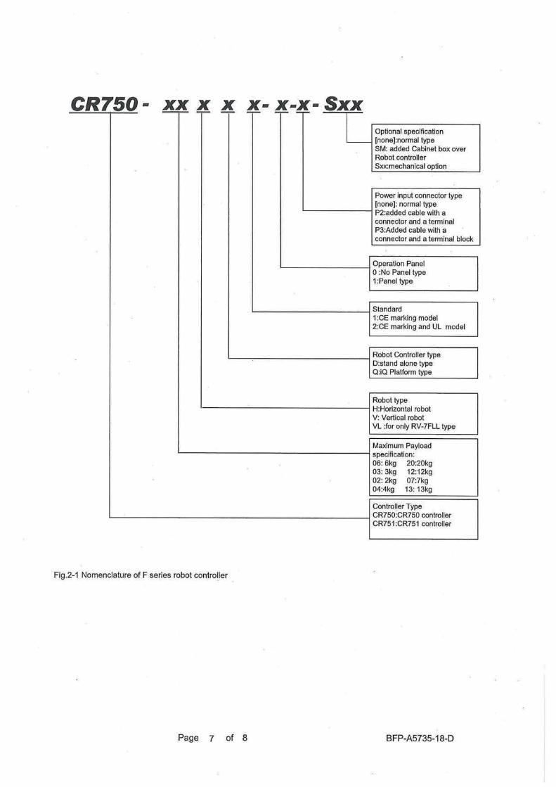


Jun., 2013 MEE Printed in Japan on recycled paper. Specifications are subject to change without notice.
HEAD OFFICE: TOKYO BUILDING, 2-7-3, MARUNOUCHI, CHIYODA-KU, TOKYO 100-8310, JAPANNAGOYA WORKS: 5-1-14, YADA-MINAMI, HIGASHI-KU, NAGOYA 461-8670, JAPAN
Authorised representative:
MITSUBISHI ELECTRIC EUROPE B.V. GERMANY
Gothaer Str. 8, 40880 Ratingen / P.O. Box 1548, 40835 Ratingen, Germany


