Safe, reliable electrical protection under critical conditions
Heinemann hydraulic magnetic circuit breakers AR and AP Series

2 EATON CORPORATION AR/AP Series Breakers CA130002EN – July 2016
Energizing a worldthat demands more.
Powering business worldwideAs a global power management company, we help customers worldwide manage the power needed for buildings, aircraft, trucks, cars, machinery and businesses.
Eaton’s innovative technologies help customers manage electrical, hydraulic and mechanical power more reliably, effi ciently, safely and sustainably.
Discover today’s Eaton.
Eaton’s electrical businessEaton is a global leader with expertise in:• Power distribution and circuit protection• Backup power protection• Solutions for harsh and hazardous environments• Lighting and security• Structural solutions and wiring devices• Control and automation• Engineering services
Eaton is positioned through its global solutions to answer today’s most critical electrical power management challenges. With 100 years of electrical experience behind us, we’re energized by the challenge of powering up a world that demands twice as much energy as today. We’re anticipating needs, engineering products and creating solutions to energize our markets today and in the future.We are dedicated to ensuring that reliable, efficient and safe power is available when it’s needed most. Eaton.com
We provide integrated
solutions that help make
energy, in all its forms,
more practical and
accessible.
With 2015 sales of
$20.9 billion, Eaton
has approximately
100,000 employees
around the world and
sells products in more
than 175 countries.
We deliver:• Electrical solutions that use less energy, improve power reliability
and make the places we live and work safer and more comfortable
• Hydraulic and electrical solutions that enable machines to deliver more productivity without wasting power
• Aerospace solutions that make aircraft lighter, safer and less costly to operate, and help airports operate more efficiently
• Vehicle drivetrain and powertrain solutions that deliver more power to cars, trucks and buses, while reducing fuel consumption and emissions
Catalog_Insert_A4_Spread_English.indd All Pages 2/12/16 4:18 PM

EATON CORPORATION AR/AP Series Breakers CA130002EN – July 2016 3
Energizing a worldthat demands more.
Powering business worldwideAs a global power management company, we help customers worldwide manage the power needed for buildings, aircraft, trucks, cars, machinery and businesses.
Eaton’s innovative technologies help customers manage electrical, hydraulic and mechanical power more reliably, effi ciently, safely and sustainably.
Discover today’s Eaton.
Eaton’s electrical businessEaton is a global leader with expertise in:• Power distribution and circuit protection• Backup power protection• Solutions for harsh and hazardous environments• Lighting and security• Structural solutions and wiring devices• Control and automation• Engineering services
Eaton is positioned through its global solutions to answer today’s most critical electrical power management challenges. With 100 years of electrical experience behind us, we’re energized by the challenge of powering up a world that demands twice as much energy as today. We’re anticipating needs, engineering products and creating solutions to energize our markets today and in the future.We are dedicated to ensuring that reliable, efficient and safe power is available when it’s needed most. Eaton.com
We provide integrated
solutions that help make
energy, in all its forms,
more practical and
accessible.
With 2015 sales of
$20.9 billion, Eaton
has approximately
100,000 employees
around the world and
sells products in more
than 175 countries.
We deliver:• Electrical solutions that use less energy, improve power reliability
and make the places we live and work safer and more comfortable
• Hydraulic and electrical solutions that enable machines to deliver more productivity without wasting power
• Aerospace solutions that make aircraft lighter, safer and less costly to operate, and help airports operate more efficiently
• Vehicle drivetrain and powertrain solutions that deliver more power to cars, trucks and buses, while reducing fuel consumption and emissions
Catalog_Insert_A4_Spread_English.indd All Pages 2/12/16 4:18 PM


EATON CORPORATION AR/AP Series Breakers CA130002EN – July 2016 5
Heinemann® hydraulic magnetic circuit breakers Contents
AMR AMP
ACPACR
ALRAER
ABR
1ContentsDescription Page
1. Product overview Hydraulic Magnetic Principle . . . . . . . . . . . . . . . . . . . . . . . . 7 Product variations . . . . . . . . . . . . . . . . . . . . . . . . . . . . . . . . . 8
2. Product configuration charts AMR – 0.1 to 100 ampere, toggle handle, front mount . . . 10 ABR – 0.1 to 100 ampere toggle handle, snap-in mount . . . 10 AER – 0.1 to 100 ampere toggle handle, sealed front . . . . . 10 ACR – 0.1 to 100 ampere, rocker handle . . . . . . . . . . . . . . . 12 ALR – 0.1 to 100 ampere, illuminated handle, front mount . 14 ACP – 100 to 200 ampere, DC, rocker handle, front mount . 16 AMP – 100 to 300 ampere, DC, front mount . . . . . . . . . . . . 18
3. Accessories Barriers . . . . . . . . . . . . . . . . . . . . . . . . . . . . . . . . . . . . . . . . 20Boots . . . . . . . . . . . . . . . . . . . . . . . . . . . . . . . . . . . . . . . . . 21 Blanking plate . . . . . . . . . . . . . . . . . . . . . . . . . . . . . . . . . . . 21 Busbars – 100 ampere . . . . . . . . . . . . . . . . . . . . . . . . . . . . 21 Busbars – 300 ampere . . . . . . . . . . . . . . . . . . . . . . . . . . . . 21 Rail standard nuts and washers M6 . . . . . . . . . . . . . . . . . . 22 Plug-in receptacle . . . . . . . . . . . . . . . . . . . . . . . . . . . . . . . . 22 Breaker removal tool . . . . . . . . . . . . . . . . . . . . . . . . . . . . . . 22
4. Related productsRemote breaker reset . . . . . . . . . . . . . . . . . . . . . . . . . . . . . 23 Power distribution unit . . . . . . . . . . . . . . . . . . . . . . . . . . . . 24
5. Technical specifications General characteristics . . . . . . . . . . . . . . . . . . . . . . . . . . . . 26 Approvals . . . . . . . . . . . . . . . . . . . . . . . . . . . . . . . . . . . . . . 27 Safety standards . . . . . . . . . . . . . . . . . . . . . . . . . . . . . . . . . 27 Internal circuits . . . . . . . . . . . . . . . . . . . . . . . . . . . . . . . . . . 28 Time delay curves . . . . . . . . . . . . . . . . . . . . . . . . . . . . . . . . 31
6. Overall dimensions AMR . . . . . . . . . . . . . . . . . . . . . . . . . . . . . . . . . . . . . . . . . . 40 ABR . . . . . . . . . . . . . . . . . . . . . . . . . . . . . . . . . . . . . . . . . . 41 ACGR . . . . . . . . . . . . . . . . . . . . . . . . . . . . . . . . . . . . . . . . . 42 ACWR . . . . . . . . . . . . . . . . . . . . . . . . . . . . . . . . . . . . . . . . . 43 ACFR . . . . . . . . . . . . . . . . . . . . . . . . . . . . . . . . . . . . . . . . . 44 AER . . . . . . . . . . . . . . . . . . . . . . . . . . . . . . . . . . . . . . . . . . 45 ALR . . . . . . . . . . . . . . . . . . . . . . . . . . . . . . . . . . . . . . . . . . 46 AMP . . . . . . . . . . . . . . . . . . . . . . . . . . . . . . . . . . . . . . . . . . 47 ACGP . . . . . . . . . . . . . . . . . . . . . . . . . . . . . . . . . . . . . . . . . 48 ACWP . . . . . . . . . . . . . . . . . . . . . . . . . . . . . . . . . . . . . . . . . 49 ACFP . . . . . . . . . . . . . . . . . . . . . . . . . . . . . . . . . . . . . . . . . 50 Terminals . . . . . . . . . . . . . . . . . . . . . . . . . . . . . . . . . . . . . . 51Auxiliary contacts . . . . . . . . . . . . . . . . . . . . . . . . . . . . . . . . 53Mid-trip alarm switch . . . . . . . . . . . . . . . . . . . . . . . . . . . . . 54
6 EATON CORPORATION AR/AP Series Breakers CA130002EN – July 2016
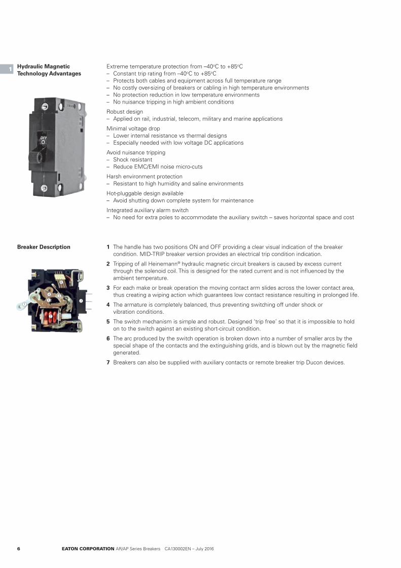
1 The handle has two positions ON and OFF providing a clear visual indication of the breaker condition. MID-TRIP breaker version provides an electrical trip condition indication.
2 Tripping of all Heinemann® hydraulic magnetic circuit breakers is caused by excess current through the solenoid coil. This is designed for the rated current and is not influenced by the ambient temperature.
3 For each make or break operation the moving contact arm slides across the lower contact area, thus creating a wiping action which guarantees low contact resistance resulting in prolonged life.
4 The armature is completely balanced, thus preventing switching off under shock or vibration conditions.
5 The switch mechanism is simple and robust. Designed ‘trip free’ so that it is impossible to hold on to the switch against an existing short-circuit condition.
6 The arc produced by the switch operation is broken down into a number of smaller arcs by the special shape of the contacts and the extinguishing grids, and is blown out by the magnetic field generated.
7 Breakers can also be supplied with auxiliary contacts or remote breaker trip Ducon devices.
Extreme temperature protection from –40oC to +85oC – Constant trip rating from –40oC to +85oC – Protects both cables and equipment across full temperature range – No costly over-sizing of breakers or cabling in high temperature environments – No protection reduction in low temperature environments – No nuisance tripping in high ambient conditions
Robust design – Applied on rail, industrial, telecom, military and marine applications
Minimal voltage drop – Lower internal resistance vs thermal designs – Especially needed with low voltage DC applications
Avoid nuisance tripping – Shock resistant – Reduce EMC/EMI noise micro-cuts
Harsh environment protection – Resistant to high humidity and saline environments
Hot-pluggable design available – Avoid shutting down complete system for maintenance
Integrated auxiliary alarm switch – No need for extra poles to accommodate the auxiliary switch – saves horizontal space and cost
Hydraulic Magnetic Technology Advantages
Breaker Description
1
1
2
34
5
6
7

EATON CORPORATION AR/AP Series Breakers CA130002EN – July 2016 7
Product OverviewHydraulic Magnetic Principle
1
1
Normal Operation
Moderate Overload Condition
Overload Condition
Short-Circuit Condition
The load current is at or below the nominal rating of the breaker. The core remains at the (left) end of the tube opposite the armature.
1. Tube 2. Core 3. Spring 4. Fluid 5. Frame 6. Coil (sensor) 7. Pole piece 8. Armature
The current is sufficient to create enough magnetic flux to move the core (to the right) compressing the springs slightly.
The magnetic flux is sufficient to move the core completely to the end of the tube (right) which attracts the armature, and trips the breaker.
The flux produced by the coil alone, regardless of the core position, is sufficient to attract the armature causing the breaker to trip. This circuit interruption occurs with no intentional delay.
1 2 3 4 7 8
5 6
Hydraulic Magnetic Tripping Mechanism
8 EATON CORPORATION AR/AP Series Breakers CA130002EN – July 2016
Product OverviewAR and AP Product variations1
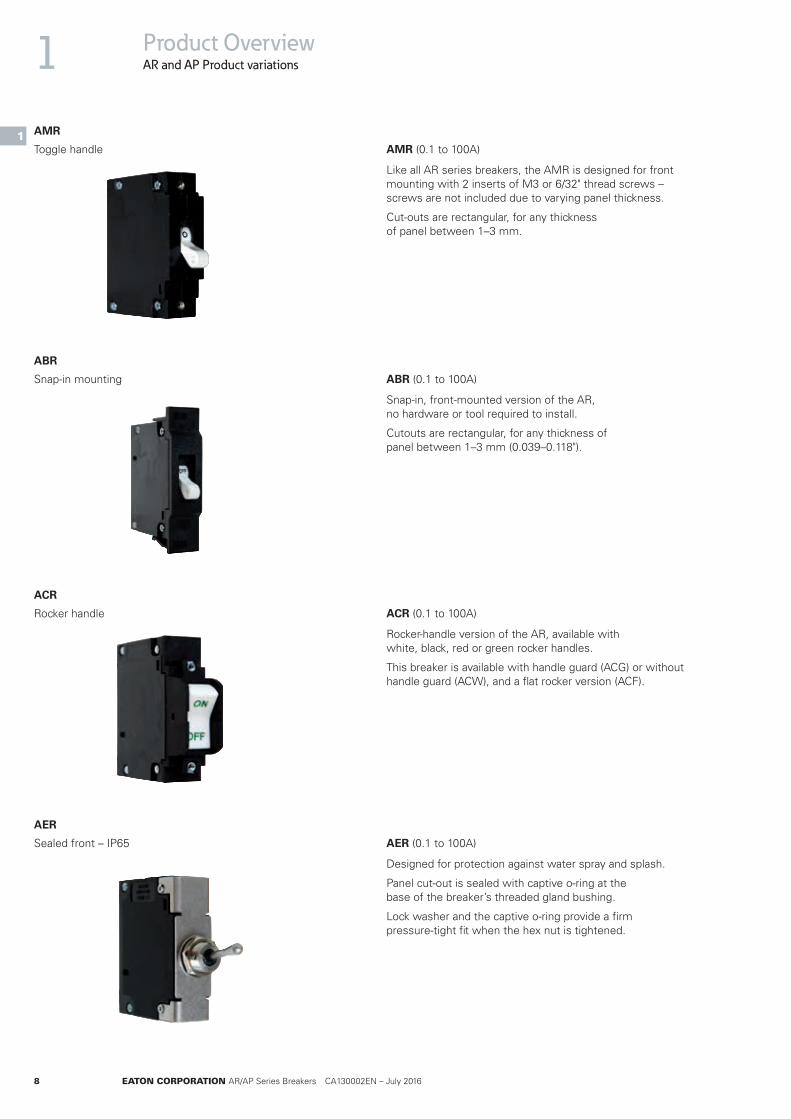
1AMR (0.1 to 100A)
Like all AR series breakers, the AMR is designed for front mounting with 2 inserts of M3 or 6/32" thread screws – screws are not included due to varying panel thickness.
Cut-outs are rectangular, for any thickness of panel between 1–3 mm.
Toggle handle
AMR
ABR (0.1 to 100A)
Snap-in, front-mounted version of the AR, no hardware or tool required to install.
Cutouts are rectangular, for any thickness of panel between 1–3 mm (0.039–0.118").
Snap-in mounting
ABR
ACR (0.1 to 100A)
Rocker-handle version of the AR, available with white, black, red or green rocker handles.
This breaker is available with handle guard (ACG) or without handle guard (ACW), and a flat rocker version (ACF).
Rocker handle
ACR
AER (0.1 to 100A)
Designed for protection against water spray and splash.
Panel cut-out is sealed with captive o-ring at the base of the breaker’s threaded gland bushing.
Lock washer and the captive o-ring provide a firm pressure-tight fit when the hex nut is tightened.
Sealed front – IP65
AER
EATON CORPORATION AR/AP Series Breakers CA130002EN – July 2016 9
Product OverviewAR and AP Product variations
1
1
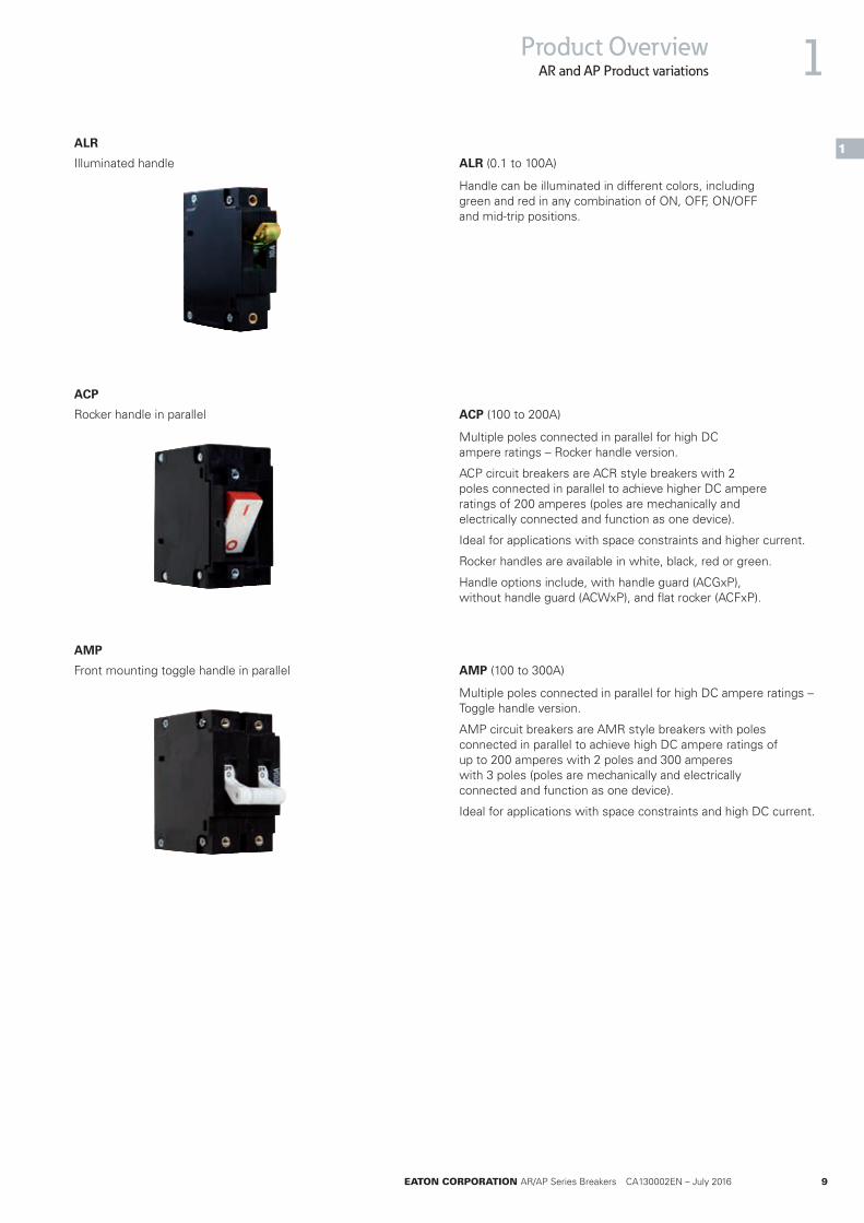
ALR (0.1 to 100A)
Handle can be illuminated in different colors, including green and red in any combination of ON, OFF, ON/OFF and mid-trip positions.
Illuminated handle
ALR
ACP (100 to 200A)
Multiple poles connected in parallel for high DC ampere ratings – Rocker handle version.
ACP circuit breakers are ACR style breakers with 2 poles connected in parallel to achieve higher DC ampere ratings of 200 amperes (poles are mechanically and electrically connected and function as one device).
Ideal for applications with space constraints and higher current.
Rocker handles are available in white, black, red or green.
Handle options include, with handle guard (ACGxP), without handle guard (ACWxP), and flat rocker (ACFxP).
Rocker handle in parallel
ACP
AMP (100 to 300A)
Multiple poles connected in parallel for high DC ampere ratings – Toggle handle version.
AMP circuit breakers are AMR style breakers with poles connected in parallel to achieve high DC ampere ratings of up to 200 amperes with 2 poles and 300 amperes with 3 poles (poles are mechanically and electrically connected and function as one device).
Ideal for applications with space constraints and high DC current.
Front mounting toggle handle in parallel
AMP
10 EATON CORPORATION AR/AP Series Breakers CA130002EN – July 2016
2
2
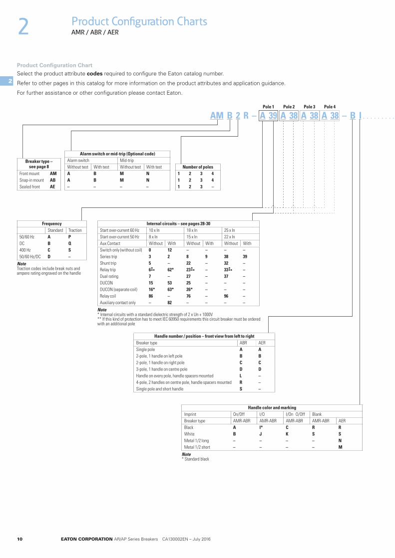
Product Configuration ChartsAMR / ABR / AER
AM B 2 R – A 39 A 38 A 38 A 38 – B I . . . . . . . . . . . . . . . . . .
Breaker type – see page 8
Front mount AMSnap-in mount ABSealed front AE
Number of poles1 2 3 41 2 3 41 2 3 –
FrequencyStandard Traction
50/60 Hz A PDC B Q400 Hz C S50/60 Hz/DC D –
Note Traction codes include break nuts and ampere rating engraved on the handle
Handle number / position – front view from left to rightBreaker type ABR AERSingle pole A A2-pole, 1 handle on left pole B B2-pole, 1 handle on right pole C C3-pole, 1 handle on centre pole D DHandle on every pole, handle spacers mounted L –4-pole, 2 handles on centre pole, handle spacers mounted R –Single pole and short handle S –
Handle color and markingImprint On/Off I/O I/On O/Off BlankBreaker type AMR-ABR AMR-ABR AMR-ABR AMR-ABR AERBlack A I* C R RWhite B J K S SMetal 1/2 long – – – – NMetal 1/2 short – – – – M
Note * Standard black
Alarm switch or mid-trip (Optional code)Alarm switch Mid-tripWithout test With test Without test With testA B M NA B M N– – – –
Product Configuration ChartSelect the product attribute codes required to configure the Eaton catalog number.
Refer to other pages in this catalog for more information on the product attributes and application guidance.
For further assistance or other configuration please contact Eaton.
Pole 1 Pole 2 Pole 3 Pole 4
Internal circuits – see pages 28-30Start over-current 60 Hz 10 x In 18 x In 25 x InStart over-current 50 Hz 8 x In 15 x In 22 x InAux Contact Without With Without With Without WithSwitch only (without coil) 0 12 – – – –Series trip 3 2 8 9 38 39Shunt trip 5 – 22 – 32 –Relay trip 6 62* 23 – 33 –Dual rating 7 – 27 – 37 –DUCON 15 53 25 – – –DUCON (separate coil) 16* 63* 26* – – –Relay coil 86 – 76 – 96 –Auxiliary contact only – 82 – – – –
Note * Internal circuits with a standard dielectric strength of 2 x Un + 1000V ** If this kind of protection has to meet IEC 60950 requirements this circuit breaker must be ordered with an additional pole
*** *** ***

EATON CORPORATION AR/AP Series Breakers CA130002EN – July 2016 11
Product Configuration ChartsAMR / ABR / AER 2
2
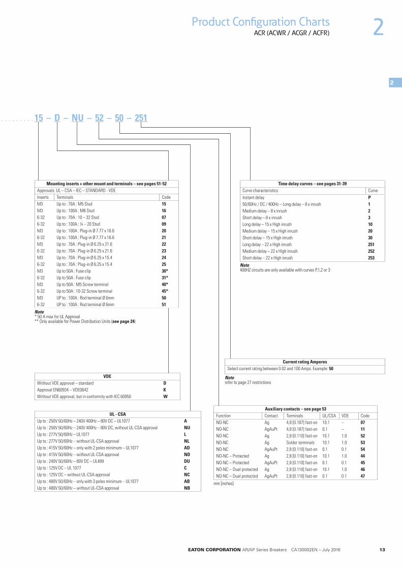
. . . . . . . . . . . . . . . . . . 15 – D – NU – 52 – 50 – 251
Mounting inserts + other mount and terminals – see pages 51-52Inserts Terminals CodeM3 Up to : 70A : M5 Stud 15M3 Up to : 100A : M6 Stud 166-32 Up to : 70A : 10 – 32 Stud 076-32 Up to : 100A : ¼ – 20 Stud 09M3 Up to : 100A : Plug-in Ø 7.77 x 16.6 206-32 Up to : 100A : Plug-in Ø 7.77 x 16.6 21M3 Up to : 70A : Plug-in Ø 6.25 x 21.6 226-32 Up to : 70A : Plug-in Ø 6.25 x 21.6 23M3 Up to : 70A : Plug-in Ø 6.25 x 15.4 246-32 Up to : 70A : Plug-in Ø 6.25 x 15.4 25M3 Up to 50A : Fuse clip 30*6-32 Up to 50A : Fuse clip 31*M3 Up to 50A : M5 Screw terminal 40*6-32 Up to 50A : 10-32 Screw terminal 45*M3 UP to : 100A : Rod terminal Ø 6mm 506-32 UP to : 100A : Rod terminal Ø 6mm 51
Note * 50A max for UL Approval AER types only available with code 15, 16, 20, 22, 24, 30, 40
Time delay curves – see pages 31-39Curve characteristics CurveInstant delay P50/60Hz / DC / 400Hz – Long delay – 8 x inrush 1Medium delay – 8 x inrush 2Short delay – 8 x inrush 3Long delay – 15 x High inrush 10Medium delay – 15 x High inrush 20Short delay – 15 x High inrush 30Long delay – 22 x High inrush 251Medium delay – 22 x High inrush 252Short delay – 22 x High inrush 253
Note 400HZ circuits are only available with curves P,1,2 or 3
Auxiliary contacts – see page 53Function Contact Terminals UL/CSA VDE CodeNO-NC Ag 4,8 [0.187] fast-on 10.1 – 07NO-NC AgAuPt 4,8 [0.187] fast-on 0.1 – 11NO-NC Ag 2,8 [0.110] fast-on 10.1 1.0 52NO-NC Ag Solder terminals 10.1 1.0 53NO-NC AgAuPt 2,8 [0.110] fast-on 0.1 0.1 54NO-NC – Protected Ag 2,8 [0.110] fast-on 10.1 1.0 44NO-NC – Protected AgAuPt 2,8 [0.110] fast-on 0.1 0.1 45NO-NC – Dual protected Ag 2,8 [0.110] fast-on 10.1 1.0 46NO-NC – Dual protected AgAuPt 2,8 [0.110] fast-on 0.1 0.1 47
mm [inches]
Current rating AmperesSelect current rating between 0.02 and 100 Amps
UL - CSAUp to : 250V 50/60Hz – 240V 400Hz – 80V DC – UL1077 AUp to : 250V 50/60Hz – 240V 400Hz – 80V DC, without UL-CSA approval NUUp to : 277V 50/60Hz – UL1077 LUp to : 277V 50/60Hz – without UL-CSA approval NLUp to : 415V 50/60Hz – only with 2 poles minimum – UL1077 ADUp to : 415V 50/60Hz – without UL-CSA approval NDUp to : 240V 50/60Hz – 80V DC – UL489 DUUp to : 125V DC – UL 1077 CUp to : 125V DC – without UL-CSA approval NCUp to : 480V 50/60Hz – only with 3 poles minimum – UL1077 ABUp to : 480V 50/60Hz – without UL-CSA approval NB
Note ABR Types UL-CSA approved AER Types no approval, so code D, NU, NL, ND, NB and NC
VDEWithout VDE approval – standard DApproval EN60934 – VDE0642 KWithout VDE approval, but in conformity with IEC 60950 W
Note refer to page 27 restrictions
12 EATON CORPORATION AR/AP Series Breakers CA130002EN – July 2016
2
2
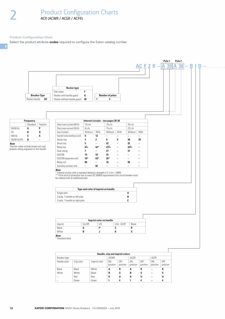
Product Configuration ChartsACR (ACWR / ACGR / ACFR)
AC F 2 R – A 39 A 38 – B I D – . . . . . . . . . . . . . . . . . .
Breaker Type Rocker handle AC
Number of poles1 2
FrequencyStandard Traction
50/60 Hz A PDC B Q400 Hz C S50/60 Hz/DC D –
Note Traction codes include break nuts and ampere rating engraved on the handle
Rocker typeFlat rocker FRocker with handle guard GRocker without handle guard W
Type and color of imprint on handleSingle pole A2-pole, 1 handle on left pole B2-pole, 1 handle on right pole C
Imprint color on handle Imprint On/Off I/O I/On O/Off BlankBlack A I* C RWhite B J K S
Note * Standard black
Product Configuration ChartSelect the product attribute codes required to configure the Eaton catalog number.
Pole 1 Pole 2
Handle, clip and imprint colorsBreaker type ACWR ACGR ACFRHandle color Clip color Imprint color ON
positionOFF position
ON position
OFF position
ON position
OFF position
Black Black White A R A R – RWhite White Black B S B S – S– Red Red D U D U – U– Green Green 1 4 1 4 – 4
Internal circuits – see pages 28-30Start over-current 60 Hz 10 x In 18 x In 25 x InStart over-current 50 Hz 8 x In 15 x In 22 x InAux Contact Without With Without With Without WithSwitch only (without coil) 0 12 – – – –Series trip 3 2 8 9 38 39Shunt trip 5 – 22 – 32 –Relay trip 6 62* 23 – 33 –Dual rating 7 – 27 – 37 –DUCON 15 53 25 – – –DUCON (separate coil) 16* 63* 26* – – –Relay coil 86 – 76 – 96 –Auxiliary contact only – 82 – – – –
Note * Internal circuits with a standard dielectric strength of 2 x Un + 1000V ** If this kind of protection has to meet IEC 60950 requirements this circuit breaker must be ordered with an additional pole
*** *** ***
EATON CORPORATION AR/AP Series Breakers CA130002EN – July 2016 13
Product Configuration ChartsACR (ACWR / ACGR / ACFR) 2
2
. . . . . . . . . . . . . . . . . .
Mounting inserts + other mount and terminals – see pages 51-52Approvals: UL – CSA – IEC – STANDARD - VDEInserts Terminals CodeM3 Up to : 70A : M5 Stud 15M3 Up to : 100A : M6 Stud 166-32 Up to : 70A : 10 – 32 Stud 076-32 Up to : 100A : ¼ – 20 Stud 09M3 Up to : 100A : Plug-in Ø 7.77 x 16.6 206-32 Up to : 100A : Plug-in Ø 7.77 x 16.6 21M3 Up to : 70A : Plug-in Ø 6.25 x 21.6 226-32 Up to : 70A : Plug-in Ø 6.25 x 21.6 23M3 Up to : 70A : Plug-in Ø 6.25 x 15.4 246-32 Up to : 70A : Plug-in Ø 6.25 x 15.4 25M3 Up to 50A : Fuse clip 30*6-32 Up to 50A : Fuse clip 31*M3 Up to 50A : M5 Screw terminal 40*6-32 Up to 50A : 10-32 Screw terminal 45*M3 UP to : 100A : Rod terminal Ø 6mm 506-32 UP to : 100A : Rod terminal Ø 6mm 51
Note * 50 A max for UL Approval ** Only available for Power Distribution Units (see page 24)
15 – D – NU – 52 – 50 – 251
Auxiliary contacts – see page 53Function Contact Terminals UL/CSA VDE CodeNO-NC Ag 4,8 [0.187] fast-on 10.1 – 07NO-NC AgAuPt 4,8 [0.187] fast-on 0.1 – 11NO-NC Ag 2,8 [0.110] fast-on 10.1 1.0 52NO-NC Ag Solder terminals 10.1 1.0 53NO-NC AgAuPt 2,8 [0.110] fast-on 0.1 0.1 54NO-NC – Protected Ag 2,8 [0.110] fast-on 10.1 1.0 44NO-NC – Protected AgAuPt 2,8 [0.110] fast-on 0.1 0.1 45NO-NC – Dual protected Ag 2,8 [0.110] fast-on 10.1 1.0 46NO-NC – Dual protected AgAuPt 2,8 [0.110] fast-on 0.1 0.1 47
mm [inches]
Current rating Amperes Select current rating between 0.02 and 100 Amps. Example: 50
UL - CSAUp to : 250V 50/60Hz – 240V 400Hz – 80V DC – UL1077 AUp to : 250V 50/60Hz – 240V 400Hz – 80V DC, without UL-CSA approval NUUp to : 277V 50/60Hz – UL1077 LUp to : 277V 50/60Hz – without UL-CSA approval NLUp to : 415V 50/60Hz – only with 2 poles minimum – UL1077 ADUp to : 415V 50/60Hz – without UL-CSA approval NDUp to : 240V 50/60Hz – 80V DC – UL489 DUUp to : 125V DC – UL 1077 CUp to : 125V DC – without UL-CSA approval NCUp to : 480V 50/60Hz – only with 3 poles minimum – UL1077 ABUp to : 480V 50/60Hz – without UL-CSA approval NB
VDEWithout VDE approval – standard DApproval EN60934 – VDE0642 KWithout VDE approval, but in conformity with IEC 60950 W
Time delay curves – see pages 31-39Curve characteristics CurveInstant delay P50/60Hz / DC / 400Hz – Long delay – 8 x inrush 1Medium delay – 8 x inrush 2Short delay – 8 x inrush 3Long delay – 15 x High inrush 10Medium delay – 15 x High inrush 20Short delay – 15 x High inrush 30Long delay – 22 x High inrush 251Medium delay – 22 x High inrush 252Short delay – 22 x High inrush 253
Note 400HZ circuits are only available with curves P,1,2 or 3
Note refer to page 27 restrictions

14 EATON CORPORATION AR/AP Series Breakers CA130002EN – July 2016
2
2
Product Configuration ChartsALR
AL B 2 R – A 39 A 38 – B D 3 – . . . . . . . . . . . . . . . . . .
Breaker TypeFront mount AL
Number of poles1 2 3
FrequencyStandard Traction
50/60 Hz A PDC B Q400 Hz C S50/60 Hz/DC D –
Note Traction codes include break nuts and ampere rating engraved on the handle
Handle number / position – front view from left to rightSingle pole A2-pole, 1 handle on left pole B2-pole, 1 handle on right pole C3-pole, 1 handle on centre pole D
Imprint and LED illumination of handleHandle illumination position
Handle imprint ON OFF Mid-trip ON/OFFON/OFF A B C DI/O E F G HI/O – ON/OFF J V V MBlank N P Q R
LED colorRed 1Green 2Red ON/Green OFF 3Green ON/Red OFF 4
Alarm switch or mid-trip (Optional code)Alarm switch Mid-tripWithout test With test Without test With test
A B M N
Product Configuration ChartSelect the product attribute codes required to configure the Eaton catalog number.
Pole 1 Pole 2
. . . . . . . . . . . . . . . . . .
Internal circuits – see pages 28-30Start over-current 60 Hz 10 x In 18 x In 25 x InStart over-current 50 Hz 8 x In 15 x In 22 x InAux Contact Without With Without With Without WithSwitch only (without coil) 0 12 – – – –Series trip 3 2 8 9 38 39Shunt trip 5 – 22 – 32 –Relay trip 6 62* 23 – 33 –Dual rating 7 – 27 – 37 –DUCON 15 53 25 – – –DUCON (separate coil) 16* 63* 26* – – –Relay coil 86 – 76 – 96 –Auxiliary contact only – 82 – – – –
Note * Internal circuits with a standard dielectric strength of 2 x Un + 1000V ** If this circuit breaker has to meet IEC 60950 requirements this circuit breaker requires 2 poles
*** *** ***
EATON CORPORATION AR/AP Series Breakers CA130002EN – July 2016 15
Product Configuration ChartsALR 2
2
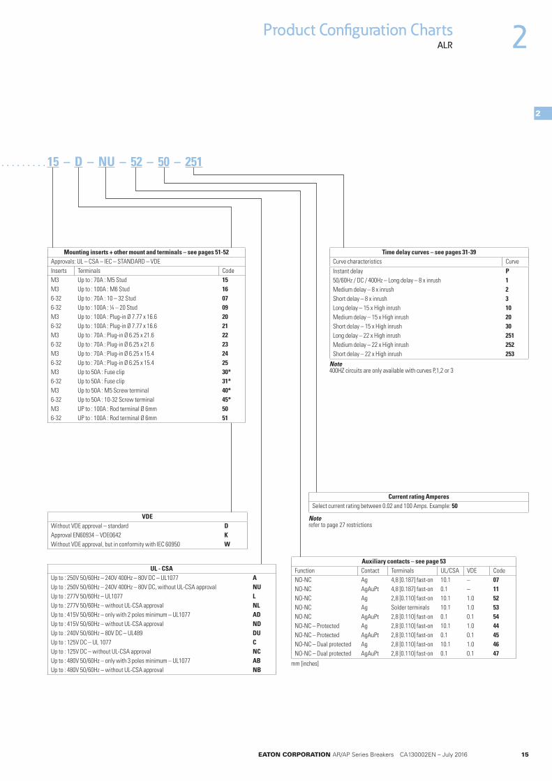
. . . . . . . . . . . . . . . . . .. . . . . . . . . . . . . . . . . . 15 – D – NU – 52 – 50 – 251
Current rating Amperes Select current rating between 0.02 and 100 Amps. Example: 50
Mounting inserts + other mount and terminals – see pages 51-52Approvals: UL – CSA – IEC – STANDARD – VDEInserts Terminals CodeM3 Up to : 70A : M5 Stud 15M3 Up to : 100A : M6 Stud 166-32 Up to : 70A : 10 – 32 Stud 076-32 Up to : 100A : ¼ – 20 Stud 09M3 Up to : 100A : Plug-in Ø 7.77 x 16.6 206-32 Up to : 100A : Plug-in Ø 7.77 x 16.6 21M3 Up to : 70A : Plug-in Ø 6.25 x 21.6 226-32 Up to : 70A : Plug-in Ø 6.25 x 21.6 23M3 Up to : 70A : Plug-in Ø 6.25 x 15.4 246-32 Up to : 70A : Plug-in Ø 6.25 x 15.4 25M3 Up to 50A : Fuse clip 30*6-32 Up to 50A : Fuse clip 31*M3 Up to 50A : M5 Screw terminal 40*6-32 Up to 50A : 10-32 Screw terminal 45*M3 UP to : 100A : Rod terminal Ø 6mm 506-32 UP to : 100A : Rod terminal Ø 6mm 51
UL - CSAUp to : 250V 50/60Hz – 240V 400Hz – 80V DC – UL1077 AUp to : 250V 50/60Hz – 240V 400Hz – 80V DC, without UL-CSA approval NUUp to : 277V 50/60Hz – UL1077 LUp to : 277V 50/60Hz – without UL-CSA approval NLUp to : 415V 50/60Hz – only with 2 poles minimum – UL1077 ADUp to : 415V 50/60Hz – without UL-CSA approval NDUp to : 240V 50/60Hz – 80V DC – UL489 DUUp to : 125V DC – UL 1077 CUp to : 125V DC – without UL-CSA approval NCUp to : 480V 50/60Hz – only with 3 poles minimum – UL1077 ABUp to : 480V 50/60Hz – without UL-CSA approval NB
VDEWithout VDE approval – standard DApproval EN60934 – VDE0642 KWithout VDE approval, but in conformity with IEC 60950 W
Time delay curves – see pages 31-39Curve characteristics CurveInstant delay P50/60Hz / DC / 400Hz – Long delay – 8 x inrush 1Medium delay – 8 x inrush 2Short delay – 8 x inrush 3Long delay – 15 x High inrush 10Medium delay – 15 x High inrush 20Short delay – 15 x High inrush 30Long delay – 22 x High inrush 251Medium delay – 22 x High inrush 252Short delay – 22 x High inrush 253
Note 400HZ circuits are only available with curves P,1,2 or 3
Auxiliary contacts – see page 53Function Contact Terminals UL/CSA VDE CodeNO-NC Ag 4,8 [0.187] fast-on 10.1 – 07NO-NC AgAuPt 4,8 [0.187] fast-on 0.1 – 11NO-NC Ag 2,8 [0.110] fast-on 10.1 1.0 52NO-NC Ag Solder terminals 10.1 1.0 53NO-NC AgAuPt 2,8 [0.110] fast-on 0.1 0.1 54NO-NC – Protected Ag 2,8 [0.110] fast-on 10.1 1.0 44NO-NC – Protected AgAuPt 2,8 [0.110] fast-on 0.1 0.1 45NO-NC – Dual protected Ag 2,8 [0.110] fast-on 10.1 1.0 46NO-NC – Dual protected AgAuPt 2,8 [0.110] fast-on 0.1 0.1 47
mm [inches]
Note refer to page 27 restrictions

16 EATON CORPORATION AR/AP Series Breakers CA130002EN – July 2016
2
2
Product Configuration ChartsACP
AC G 1 P – B 39 B 38 – B I I – . . . . . . . . . . . . . . . . . .
Breaker Type Rocker handle AC
Number of polesMaxi 200A (2 poles //) 1
Frequency Standard Traction
DC B Q
Note Traction codes include break nuts and ampere rating engraved on handle
Rocker typeFlat rocker FHandle guard GWithout handle guard W
Handle number / position – front view from left to right 2-pole, 1 handle on left pole B2-pole, 1 handle on right pole C
Internal circuits – see pages 28-30Start over-current 60 Hz 10 x In 18 x In 25 x InStart over-current 50 Hz 8 x In 15 x In 22 x InAux Contact Without With Without With Without WithSwitch only (without coil) 0 12 – – – –Series trip 3 2 8 9 38 39
Handle color and markingImprint On/Off I/O I/On O/Off BlankBlack A I* C RWhite B J K S
Note * Standard black Other colors available on request
Product Configuration ChartSelect the product attribute codes required to configure the Eaton catalog number.
Pole 1 Pole 2
Handle, clip and imprint colorsBreaker type ACWP ACGP ACFPHandle color Clip color Imprint color ON OFF ON OFF ON OFFBlack Black White A R A R – RWhite White Black B S B S – S– Red Red D U D U – U– Green Green 1 4 1 4 – 4
Note * Standard black in position OFF

EATON CORPORATION AR/AP Series Breakers CA130002EN – July 2016 17
Product Configuration ChartsACP 2
2
. . . . . . . . . . . . . . . . . . 15 – D – NU – 52 – 150 – 251
Mounting inserts + other mount and terminals – see pages 51-52Inserts Terminals CodeM3 Up to : 70A/pole : M5 Stud 15M3 Up to : 100A/pole : M6 Stud 166-32 Up to : 70A/pole : 10 – 32 Stud 076-32 Up to : 100A/pole : ¼ – 20 Stud 09M3 Up to : 100A/pole : Plug-in Ø 7.77 x 16.6 206-32 Up to : 100A/pole : Plug-in Ø 7.77 x 16.6 21
Note Given current is the max value per pole
Time delay curves – see pages 31-39Curve characteristics CurveInstant delay PLong delay – 8 x High inrush 1Medium delay – 8 x High inrush 2Short delay – 8 x High inrush 3Long delay – 15 x High inrush 10Medium delay – 15 x High inrush 20Short delay – 15 x High inrush 30Long delay – 22 x High inrush 251Medium delay – 22 x High inrush 252Short delay – 22 x High inrush 253
VDE Without VDE approval – standard DWithout VDE approval, but in conformity with IEC 60950 WApproval EN 60947-2 HApproval EN60934 – VDE0642 K
UL – CSAUp to : 80V DC – UL1077 AUP to : 80V DC, without UL-CSA approval NUUp to : 80V DC – UL 489A AUUp to : 80V DC – UL 489 DU
Current rating AmperesSelect current rating between 100 and 200 Amps
Auxiliary contacts – see page 53Function Contact Terminals UL/CSA VDE CodeNO-NC Ag 4,8 [0.187] fast-on 10.1 – 07NO-NC AgAuPt 4,8 [0.187] fast-on 0.1 – 11NO-NC Ag 2,8 [0.110] fast-on 10.1 1.0 52NO-NC Ag Solder terminals 10.1 1.0 53NO-NC AgAuPt 2,8 [0.110] fast-on 0.1 0.1 54NO-NC – Protected Ag 2,8 [0.110] fast-on 10.1 1.0 44NO-NC – Protected AgAuPt 2,8 [0.110] fast-on 0.1 0.1 45NO-NC – Dual protected Ag 2,8 [0.110] fast-on 10.1 1.0 46NO-NC – Dual protected AgAuPt 2,8 [0.110] fast-on 0.1 0.1 47
mm [inches]
Note refer to page 27 restrictions

18 EATON CORPORATION AR/AP Series Breakers CA130002EN – July 2016
2
2
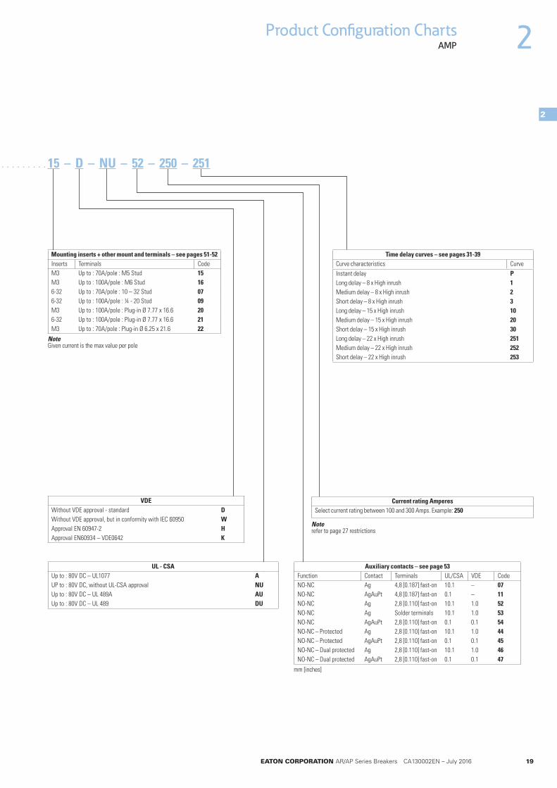
Product Configuration ChartsAMP
AM B 1 P – B 39 B 38 B 38 – L I – . . . . . . . . . . . . . . . . . .
Breaker Type Front mount AM
Number of poles200 A (2 poles in //) 1300 A (3 poles in //) 1
FrequencyStandard Traction
DC B Q
Note Traction codes include break nuts and ampere rating engraved on handle
Handle number / position – front view from left to right Handle on every pole, handle spacers mounted L
Internal circuits – see pages 28-30Start over-current 60 Hz 10 x In 18 x In 25 x InStart over-current 50 Hz 8 x In 15 x In 22 x InAux Contact Without With Without With Without WithSwitch only (without coil) 0 12 – – – –Series trip 3 2 8 9 38 39
ImprintImprint ON/OFF I/O I/ON O/OFF BlankBlack A I* C RWhite B J K S
Note * Standard black Other color available on request
Alarm switch or mid-trip optionAlarm switch Mid-tripWithout test With test Without test With testA B M N
Product Configuration ChartSelect the product attribute codes required to configure the Eaton catalog number.
Pole 1 Pole 2 Pole 3
EATON CORPORATION AR/AP Series Breakers CA130002EN – July 2016 19
Product Configuration ChartsAMP 2
2
15 – D – NU – 52 – 250 – 251. . . . . . . . . . . . . . . . . .
Mounting inserts + other mount and terminals – see pages 51-52Inserts Terminals CodeM3 Up to : 70A/pole : M5 Stud 15M3 Up to : 100A/pole : M6 Stud 166-32 Up to : 70A/pole : 10 – 32 Stud 076-32 Up to : 100A/pole : ¼ - 20 Stud 09M3 Up to : 100A/pole : Plug-in Ø 7.77 x 16.6 206-32 Up to : 100A/pole : Plug-in Ø 7.77 x 16.6 21M3 Up to : 70A/pole : Plug-in Ø 6.25 x 21.6 22
Note Given current is the max value per pole
Current rating Amperes Select current rating between 100 and 300 Amps. Example: 250
VDE Without VDE approval - standard DWithout VDE approval, but in conformity with IEC 60950 WApproval EN 60947-2 HApproval EN60934 – VDE0642 K
UL - CSAUp to : 80V DC – UL1077 AUP to : 80V DC, without UL-CSA approval NUUp to : 80V DC – UL 489A AUUp to : 80V DC – UL 489 DU
Time delay curves – see pages 31-39Curve characteristics CurveInstant delay PLong delay – 8 x High inrush 1Medium delay – 8 x High inrush 2Short delay – 8 x High inrush 3Long delay – 15 x High inrush 10Medium delay – 15 x High inrush 20Short delay – 15 x High inrush 30Long delay – 22 x High inrush 251Medium delay – 22 x High inrush 252Short delay – 22 x High inrush 253
Auxiliary contacts – see page 53Function Contact Terminals UL/CSA VDE CodeNO-NC Ag 4,8 [0.187] fast-on 10.1 – 07NO-NC AgAuPt 4,8 [0.187] fast-on 0.1 – 11NO-NC Ag 2,8 [0.110] fast-on 10.1 1.0 52NO-NC Ag Solder terminals 10.1 1.0 53NO-NC AgAuPt 2,8 [0.110] fast-on 0.1 0.1 54NO-NC – Protected Ag 2,8 [0.110] fast-on 10.1 1.0 44NO-NC – Protected AgAuPt 2,8 [0.110] fast-on 0.1 0.1 45NO-NC – Dual protected Ag 2,8 [0.110] fast-on 10.1 1.0 46NO-NC – Dual protected AgAuPt 2,8 [0.110] fast-on 0.1 0.1 47
mm [inches]
Note refer to page 27 restrictions
20 EATON CORPORATION AR/AP Series Breakers CA130002EN – July 2016
Accessories
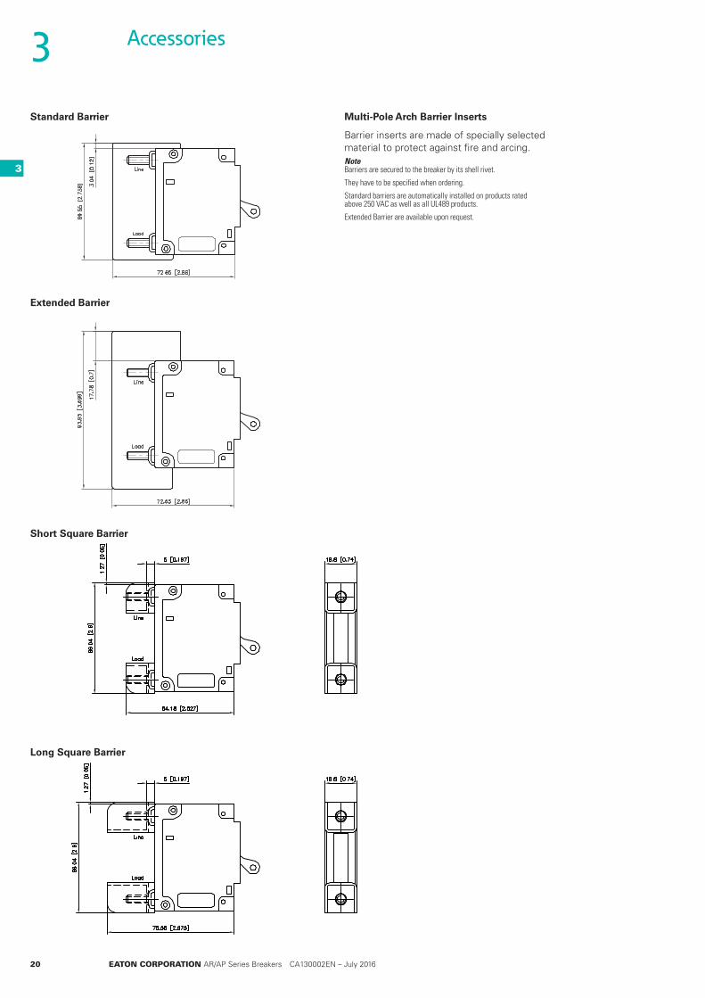
Multi-Pole Arch Barrier Inserts
Barrier inserts are made of specially selected material to protect against fire and arcing.Note Barriers are secured to the breaker by its shell rivet.
They have to be specified when ordering.
Standard barriers are automatically installed on products rated above 250 VAC as well as all UL489 products.
Extended Barrier are available upon request.
Standard Barrier
Extended Barrier
Short Square Barrier
Long Square Barrier
3
3

EATON CORPORATION AR/AP Series Breakers CA130002EN – July 2016 21
Boots (IP 65)
This Silicone rubber boot ensures a perfect water-tight front face.
Boots are delivered with 6-32 UNC screw.
Blanking Plate
Busbars
Tin-plated copper busbars rated for up to 100 amperes enable a common power connection to 2,4 or 8 breakers, eliminating the need to wire power individually to each breaker. Other busbar variations are possible.
Accessories
200 and 300 Ampere Busbar
This busbar device provides a single power connection point to 2 or 3 paralleled breakers (AM1P Series) for applications up to 200 A or 300 A respectively. Other busbar variations are possible including delivery with a simple hole or crimped insert for lug connections.
Part Number
AM1R K25104LLAM2R K25103LLAM3R K25102LLAM4R K25106LL
Part Number
AM2R K12305LLAM4R K12304LLAM8R K12303LL
Part Number
AM2R K03530LLAM3R K03531LL
Part Number
AR K20802LLACR K20803LL
3
3

22 EATON CORPORATION AR/AP Series Breakers CA130002EN – July 2016
Rail Standard Nuts and Washer M6
Plug-in Receptacle
K03860LL
K07449LL
Breaker Removal Tool
Accessories
Part Number
1 x HFR Nuts K03037LL1 x Onduflex washer K03039LL1 x Flat washer K03038LL
Part Number
K03860LLK07449LL
Part Number
K20050LL
3
3

EATON CORPORATION AR/AP Series Breakers CA130002EN – July 2016 23
Related ProductsRemote Breaker Reset – RBR Series
Series ARJS AR
Maximum number of poles to reset
1 pole up to 4 poles
Electrical characteristics
Operatig voltage 24-48-72-110 VDC
Type of signal Pulse
Operating conditions, standards and approvals
Operating temperature -40°C to +55°C (-40°F to +131°F)
Approvals - Rail EN 50155, NFF 61373, NFF 16102, VDC0580, NFC79300
Testing 10'000 Cycles (2 cycles per minute)
Physical characteristics
Dimensions WxHxD (mm) 19x 60x 20 mm 35 x 57 x 35 mm
Dimensions WxHxD (inches) 0.75" x 2.36" x 079" 1.38" x 2.25" x 1.38"
Weight 65 grams (2.29 oz) 300 g (10.6 oz)
Mounting, Terminals
Power Connection SMS 3 pin SMS 3pin / Hirshmann 4 faston
Mounting plate thickmess 2 to 5mm (0.079" to 0.197")
Note: Technical information may differ by product variation, please contact your Eaton representative for more detailed information.In the interests of continual product improvement all specifications are subject to change without notice.
Circuit Breaker closed (protected circuit is powered)
Circuit Breaker opens (current is cut in the protected circuit)
RBR rest signal pulse sent to RBR for reset instruction: RBR actuates the Circuit Breaker handle
RBR returns to initial configuration (by gravity)
The Remote Breaker Reset (RBR) allows user to remotely reset a circuit breaker after it has been opened. The RBR is designed to work with Eaton Heinemann AR series breakers for applications that require remote circuit breaker control.
Thanks to it mounting directly under the circuit breaker handle, the RBR saves valuable horizontal space and allows fast and reliable closing of the protected circuit once fault has been cleared.
The speed of actuation also resolves timing issues compared to other
solutions available on the market, and avoids arcing during reset under overload or short circuit conditions
RBR devices are available in 4 voltage ratings and two sizes, depending on application and number of poles to reset.
4
4
24 EATON CORPORATION AR/AP Series Breakers CA130002EN – July 2016
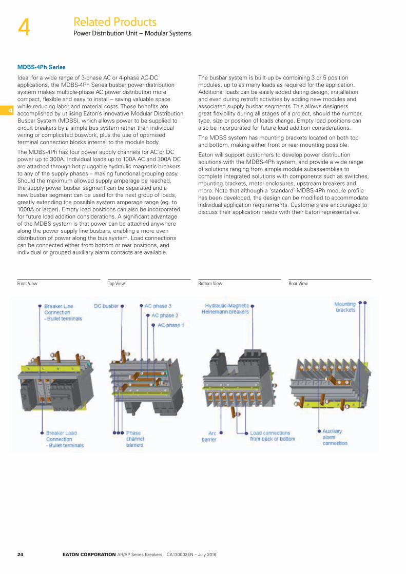
MDBS-4Ph Series
Ideal for a wide range of 3-phase AC or 4-phase AC-DC applications, the MDBS-4Ph Series busbar power distribution system makes multiple-phase AC power distribution more compact, flexible and easy to install – saving valuable space while reducing labor and material costs. These benefits are accomplished by utilising Eaton’s innovative Modular Distribution Busbar System (MDBS), which allows power to be supplied to circuit breakers by a simple bus system rather than individual wiring or complicated buswork, plus the use of optimised terminal connection blocks internal to the module body.
The MDBS-4Ph has four power supply channels for AC or DC power up to 300A. Individual loads up to 100A AC and 300A DC are attached through hot pluggable hydraulic magnetic breakers to any of the supply phases – making functional grouping easy. Should the maximum allowed supply amperage be reached, the supply power busbar segment can be separated and a new busbar segment can be used for the next group of loads, greatly extending the possible system amperage range (eg. to 1000A or larger). Empty load positions can also be incorporated for future load addition considerations. A significant advantage of the MDBS system is that power can be attached anywhere along the power supply line busbars, enabling a more even distribution of power along the bus system. Load connections can be connected either from bottom or rear positions, and individual or grouped auxiliary alarm contacts are available.
The busbar system is built-up by combining 3 or 5 position modules, up to as many loads as required for the application. Additional loads can be easily added during design, installation and even during retrofit activities by adding new modules and associated supply busbar segments. This allows designers great flexibility during all stages of a project, should the number, type, size or position of loads change. Empty load positions can also be incorporated for future load addition considerations.
The MDBS system has mounting brackets located on both top and bottom, making either front or rear mounting possible.
Eaton will support customers to develop power distribution solutions with the MDBS-4Ph system, and provide a wide range of solutions ranging from simple module subassemblies to complete integrated solutions with components such as switches, mounting brackets, metal enclosures, upstream breakers and more. Note that although a ‘standard’ MDBS-4Ph module profile has been developed, the design can be modified to accommodate individual application requirements. Customers are encouraged to discuss their application needs with their Eaton representative.
Front View Top View Bottom View Rear View
Related ProductsPower Distribution Unit – Modular Systems4
4
EATON CORPORATION AR/AP Series Breakers CA130002EN – July 2016 25
Related ProductsPower Distribution Unit – Modular Systems
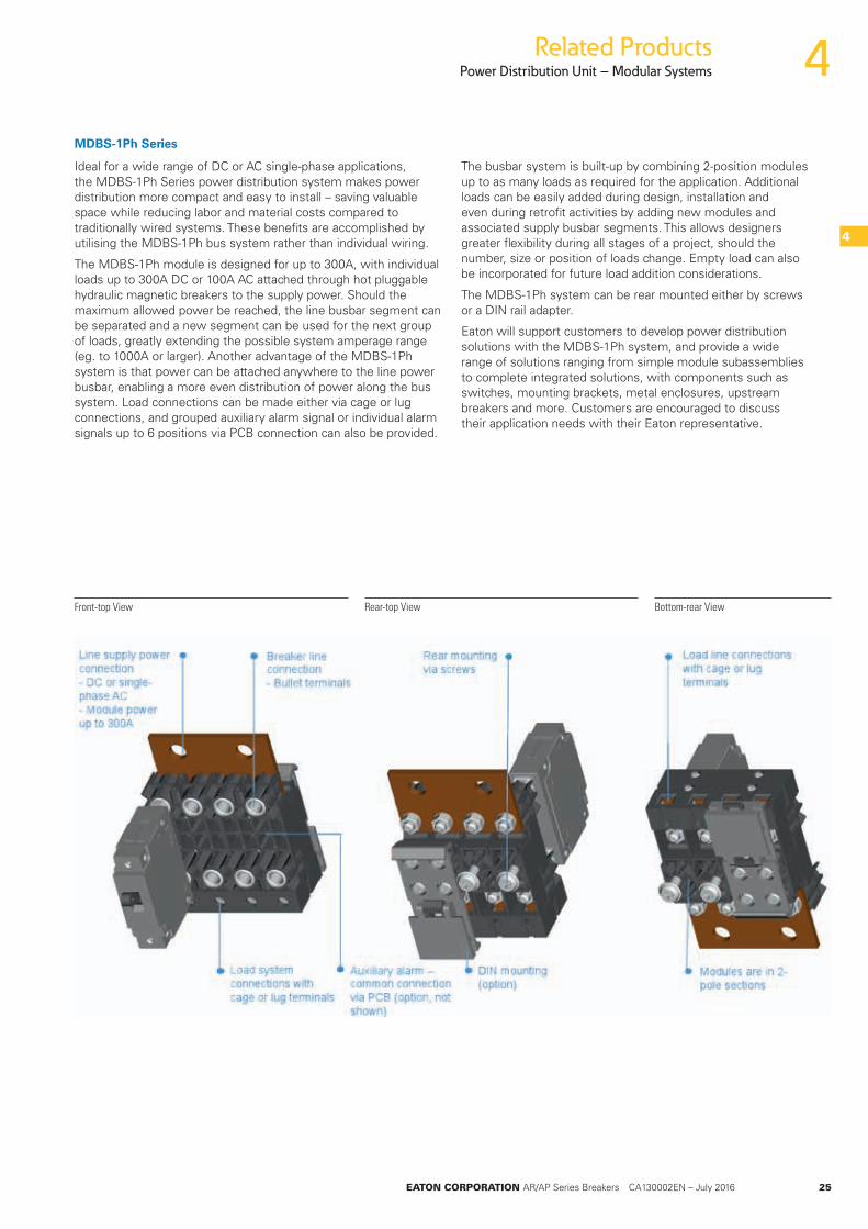
MDBS-1Ph Series
Ideal for a wide range of DC or AC single-phase applications, the MDBS-1Ph Series power distribution system makes power distribution more compact and easy to install – saving valuable space while reducing labor and material costs compared to traditionally wired systems. These benefits are accomplished by utilising the MDBS-1Ph bus system rather than individual wiring.
The MDBS-1Ph module is designed for up to 300A, with individual loads up to 300A DC or 100A AC attached through hot pluggable hydraulic magnetic breakers to the supply power. Should the maximum allowed power be reached, the line busbar segment can be separated and a new segment can be used for the next group of loads, greatly extending the possible system amperage range (eg. to 1000A or larger). Another advantage of the MDBS-1Ph system is that power can be attached anywhere to the line power busbar, enabling a more even distribution of power along the bus system. Load connections can be made either via cage or lug connections, and grouped auxiliary alarm signal or individual alarm signals up to 6 positions via PCB connection can also be provided.
The busbar system is built-up by combining 2-position modules up to as many loads as required for the application. Additional loads can be easily added during design, installation and even during retrofit activities by adding new modules and associated supply busbar segments. This allows designers greater flexibility during all stages of a project, should the number, size or position of loads change. Empty load can also be incorporated for future load addition considerations.
The MDBS-1Ph system can be rear mounted either by screws or a DIN rail adapter.
Eaton will support customers to develop power distribution solutions with the MDBS-1Ph system, and provide a wide range of solutions ranging from simple module subassemblies to complete integrated solutions, with components such as switches, mounting brackets, metal enclosures, upstream breakers and more. Customers are encouraged to discuss their application needs with their Eaton representative.
Front-top View Rear-top View Bottom-rear View
4
4
26 EATON CORPORATION AR/AP Series Breakers CA130002EN – July 2016
Technical SpecificationsGeneral Characteristics5
5
Technical characteristics
Operating Temperature –40°C +85°CStorage Temperature –40°C +85°CHumidity IEC 60068-2-78
and MIL-STD-202 Method 103 Test A
Protection IEC 60529 IP 65 AER Handle IP 40 Front sealing IP 00 Back terminals sealingShock IEC 60068-2-27 MIL-STD-202, method 213 cond 1 100 G, 6 msVibration IEC 60068-2-6 MIL-STD-202, method 204 10 to 500 Hz 10 G Amplitude 1.52mmVibrations IEC 61373 (Rail) Cat. 1 Classe BLife 10 000 switching operations** Approx. weights AR 1-pole 100 g = 0.22 lbs 2-pole 200 g = 0.44 lbs 3-pole 300 g = 0.66 lbs 4-pole 400 g = 0.88 lbsApprovals UL - NF F - CSA- IEC - CCC - GOST In conformity with IEC 60950Rail Approvals NF F 16-101 & NF F 16-102 (A1) Fire test NF F 62-001 Rolling Stock NF EN60068-2-1 cold test NF EN60068-2-2 dry heat test NF F60068-2-1 Salt spray 500h IEC 61373 vibrations IEC 45545-2 Fire & SmokeDielectric strength Up to 3750V AC 50/60HzInsulation resistance 100 MΩ under 500V DCAuxiliary switches 220V AC : 10A Rated current (contact AgAuPt)Time delay Wide range available, see pages 31-39* Shock and vibration tests are conducted with breakers carrying full rated current.
Shock and vibration specifications apply to time delay breakers only
** Meet UL endurance requirements
*** Refer to configuration chart on page 11
Note:
Technical characteristics are subject to modifications based on testing and approval compliance results.
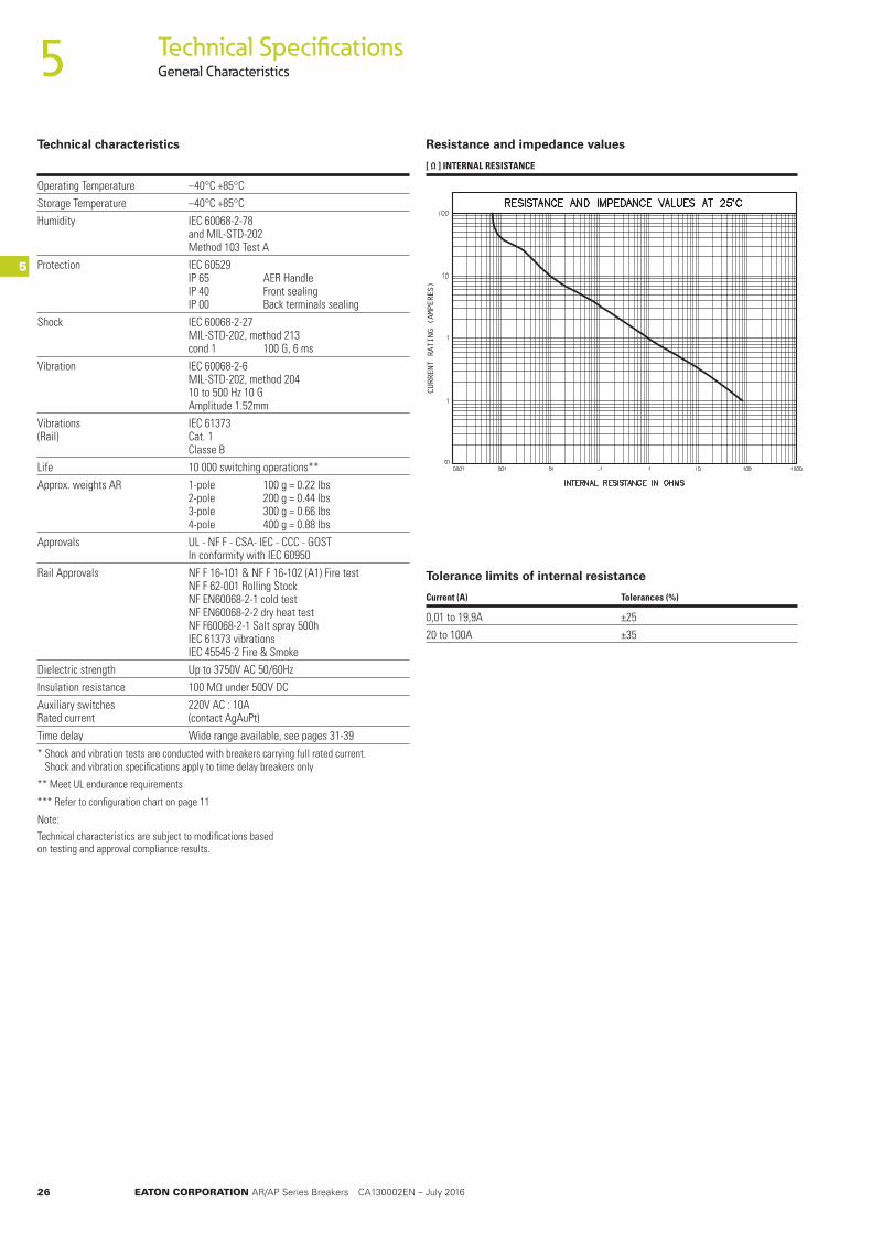
Resistance and impedance values
[ Ω ] INTERNAL RESISTANCE
Tolerance limits of internal resistance
Current (A) Tolerances (%)
0,01 to 19,9A ±2520 to 100A ±35
CURRENT RATING (AMPERES)
EATON CORPORATION AR/AP Series Breakers CA130002EN – July 2016 27
5
5
Technical SpecificationsApprovals and safety standards
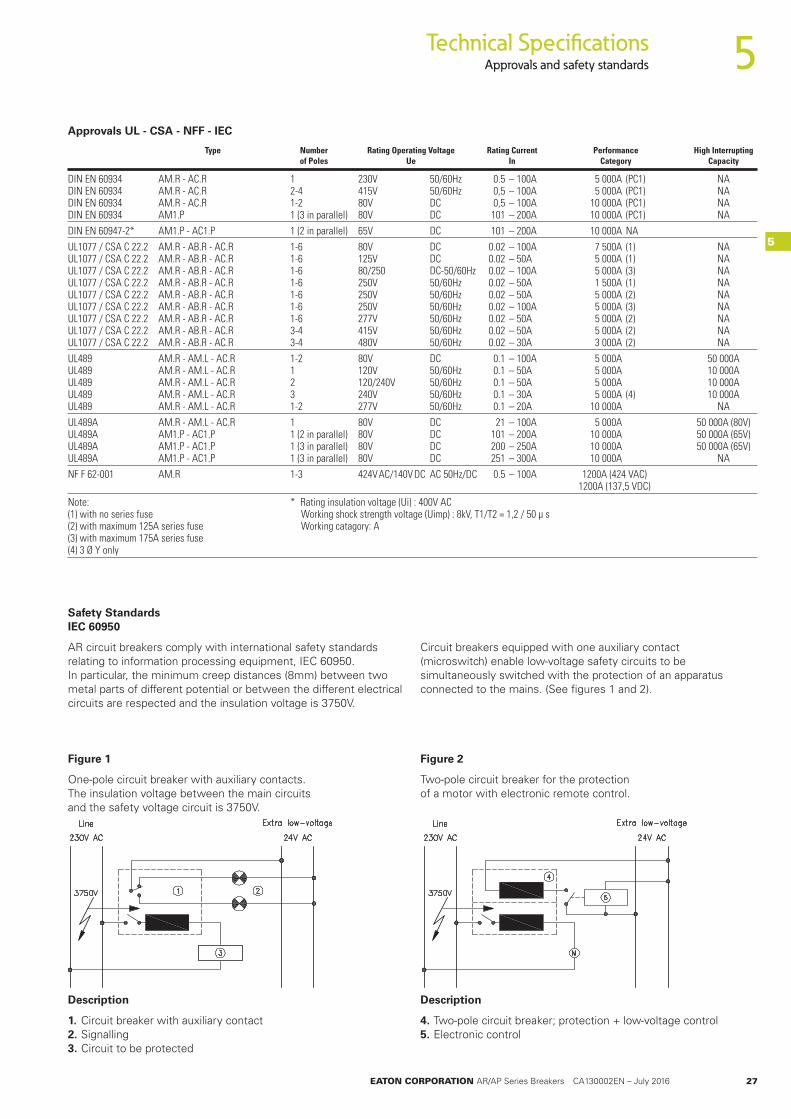
Figure 1
One-pole circuit breaker with auxiliary contacts. The insulation voltage between the main circuits and the safety voltage circuit is 3750V.
Figure 2
Two-pole circuit breaker for the protection of a motor with electronic remote control.
Approvals UL - CSA - NFF - IEC
Type Number Rating Operating Voltage Rating Current Performance High Interrupting of Poles Ue In Category Capacity
DIN EN 60934 AM.R - AC.R 1 230V 50/60Hz 0.5 – 100A 5 000A (PC1) NA DIN EN 60934 AM.R - AC.R 2-4 415V 50/60Hz 0,5 – 100A 5 000A (PC1) NA DIN EN 60934 AM.R - AC.R 1-2 80V DC 0,5 – 100A 10 000A (PC1) NA DIN EN 60934 AM1.P 1 (3 in parallel) 80V DC 101 – 200A 10 000A (PC1) NADIN EN 60947-2* AM1.P - AC1.P 1 (2 in parallel) 65V DC 101 – 200A 10 000A NAUL1077 / CSA C 22.2 AM.R - AB.R - AC.R 1-6 80V DC 0.02 – 100A 7 500A (1) NA UL1077 / CSA C 22.2 AM.R - AB.R - AC.R 1-6 125V DC 0.02 – 50A 5 000A (1) NA UL1077 / CSA C 22.2 AM.R - AB.R - AC.R 1-6 80/250 DC-50/60Hz 0.02 – 100A 5 000A (3) NA UL1077 / CSA C 22.2 AM.R - AB.R - AC.R 1-6 250V 50/60Hz 0.02 – 50A 1 500A (1) NA UL1077 / CSA C 22.2 AM.R - AB.R - AC.R 1-6 250V 50/60Hz 0.02 – 50A 5 000A (2) NA UL1077 / CSA C 22.2 AM.R - AB.R - AC.R 1-6 250V 50/60Hz 0.02 – 100A 5 000A (3) NA UL1077 / CSA C 22.2 AM.R - AB.R - AC.R 1-6 277V 50/60Hz 0.02 – 50A 5 000A (2) NA UL1077 / CSA C 22.2 AM.R - AB.R - AC.R 3-4 415V 50/60Hz 0.02 – 50A 5 000A (2) NA UL1077 / CSA C 22.2 AM.R - AB.R - AC.R 3-4 480V 50/60Hz 0.02 – 30A 3 000A (2) NAUL489 AM.R - AM.L - AC.R 1-2 80V DC 0.1 – 100A 5 000A 50 000A UL489 AM.R - AM.L - AC.R 1 120V 50/60Hz 0.1 – 50A 5 000A 10 000A UL489 AM.R - AM.L - AC.R 2 120/240V 50/60Hz 0.1 – 50A 5 000A 10 000A UL489 AM.R - AM.L - AC.R 3 240V 50/60Hz 0.1 – 30A 5 000A (4) 10 000A UL489 AM.R - AM.L - AC.R 1-2 277V 50/60Hz 0.1 – 20 A 10 000A NAUL489A AM.R - AM.L - AC.R 1 80V DC 21 – 100A 5 000A 50 000A (80V) UL489A AM1.P - AC1.P 1 (2 in parallel) 80V DC 101 – 200A 10 000A 50 000A (65V) UL489A AM1.P - AC1.P 1 (3 in parallel) 80V DC 200 – 250A 10 000A 50 000A (65V) UL489A AM1.P - AC1.P 1 (3 in parallel) 80V DC 251 – 300A 10 000A NANF F 62-001 AM.R 1-3 424V AC/140V DC AC 50Hz/DC 0.5 – 100A 1200A (424 VAC) 1200A (137,5 VDC) Note: * Rating insulation voltage (Ui) : 400V AC (1) with no series fuse Working shock strength voltage (Uimp) : 8kV, T1/T2 = 1,2 / 50 μ s (2) with maximum 125A series fuse Working catagory: A (3) with maximum 175A series fuse (4) 3 Ø Y only
Safety Standards IEC 60950
AR circuit breakers comply with international safety standards relating to information processing equipment, IEC 60950. In particular, the minimum creep distances (8mm) between two metal parts of different potential or between the different electrical circuits are respected and the insulation voltage is 3750V.
Circuit breakers equipped with one auxiliary contact (microswitch) enable low-voltage safety circuits to be simultaneously switched with the protection of an apparatus connected to the mains. (See figures 1 and 2).
Description
1. Circuit breaker with auxiliary contact 2. Signalling 3. Circuit to be protected
Description
4. Two-pole circuit breaker; protection + low-voltage control 5. Electronic control

28 EATON CORPORATION AR/AP Series Breakers CA130002EN – July 2016
Technical SpecificationsInternal Circuits5
5
Switch
Description
Switch only (without coil) with or without auxiliary contact.
Auxiliary contact Code
With 12Without 0
Series trip
Description
The contacts and the coil are in series. This is the current execution of the AR circuit breaker.
It is often used as main switch at the same time.
Inrush Code
8x 315x 822x 38
Series trip with auxiliary contact
Description
The contacts and the coil are in series. Auxiliary contacts are placed behind the circuit breaker and mechanically connected to the releasing system.
Inrush Code
8x 215x 922x 39
Shunt trip
Description
Enables two loads to be checked by means of a single circuit breaker. However it only releases if there is an overload in the main circuit. The sum of the two nominal currents must not exceed the peak current of the contacts. It is also possible to calibrate the trip point through a potentiometer connected between the shunt terminal (3)D and the load terminal (2)A.
Inrush Code
8x 515x 2222x 32
EATON CORPORATION AR/AP Series Breakers CA130002EN – July 2016 29
5
5
Technical SpecificationsInternal Circuits
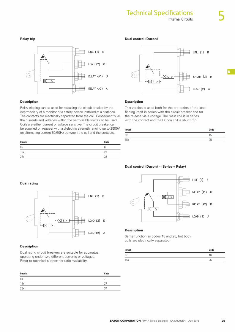
Relay trip
Description
Relay tripping can be used for releasing the circuit breaker by the intermediary of a monitor or a safety device installed at a distance. The contacts are electrically separated from the coil. Consequently, all the currents and voltages within the permissible limits can be used. Coils are either current or voltage sensitive. The circuit breaker can be supplied on request with a dielectric strength ranging up to 2500V on alternating current 50/60Hz between the coil and the contacts.
Inrush Code
8x 615x 2322x 33
Dual rating
Description
Dual rating circuit breakers are suitable for apparatus operating under two different currents or voltages. Refer to technical support for ratio availability.
Inrush Code
8x 715x 2722x 37
Dual control (Ducon)
Description
This version is used both for the protection of the load finding itself in series with the circuit breaker and for the release via a voltage. The main coil is in series with the contact and the Ducon coil is shunt trip.
Inrush Code
8x 1515x 25
Dual control (Ducon) – (Series + Relay)
Description
Same function as codes 15 and 25, but both coils are electrically separated.
Inrush Code
8x 1615x 26

30 EATON CORPORATION AR/AP Series Breakers CA130002EN – July 2016
Technical SpecificationsInternal Circuits
Relay trip for IEC execution
Auxiliary contact
Auxiliary contacts
Description
These internal circuits have no main contact. When combined with another pole, they permit compliance with the safety regulations dictated by IEC 60950.
The minimum required creepage distance between two galvanically separated electric circuits can thus be attained. (see page 28).
Note: This breaker should always be combined with one or other poles.
Description
Auxiliary contact only, without main contact and coil.
Note: This breaker should always be combined with one or other poles.
Inrush Code
8x 8615x 7622x 96
Auxiliary contact Code
With 82
5
5

EATON CORPORATION AR/AP Series Breakers CA130002EN – July 2016 31
Technical SpecificationsTime Delay Curves
5
5
Time delay curve codes are based on the following selection of high-inrush values:
Tripping specification
All curves describe breaker response with no preloading. Curves are plotted at an ambient temperature of 25°C, with breakers in the standard wall-mount position.
All circuit breakers shall hold 100% rated load continuously.
Breakers for 50/60Hz or DC service may trip between 101% and 125% rated load, must trip at 125% and above, as shown on the time-delay curve selected. (150% for 400Hz).
Non-time-delay circuit breakers (P curve) may trip instantaneously between 101% and 125% of rated load, must trip instantaneously at 125% for 50/60Hz or DC. (150% for 400Hz).
The voltage trip breakers may trip below 100% rated voltage, must trip at 100% and above: They are only available in no-time-delay construction (P curve).
AR and AP series are available with various levels of high-inrush currents, avoiding nuisance tripping during short starting periods.
In case of motor protections that would, for example, cause a steep wave front transient of very high current amplitude and short duration of overload, the breaker would not trip.
By using high-inrush tripping types, unnecessary and dangerous over calibrations involving use of thicker cables or wires can be avoided, thus saving energy and money.
The magnetic shunt used offers maximum possibilities on inrushes values at 800%, 1500% or 2200% xIn for 50Hz and 1000%, 1800% or 2500% xIn for 60Hz during a half wave period of 10ms and 8ms at respectively 50Hz and 60Hz.
Inrush Codes
8x 1 2 315x 10 20 3022x 251 252 253
High-inrush rates valid for different curves
Curve P 50/60Hz, 400Hz, DC
Curve P 50/60Hz/DC/400Hz Instant Delay (Max.time)
In. % 125 135 150 200 300 400 500 600 700 800 900 1000 1100 1200
Max 0.100 0.060 0.050 0.034 0.020 0.015 0.012 0.011 0.011 0.011 0.011 0.011 0.011 0.011

32 EATON CORPORATION AR/AP Series Breakers CA130002EN – July 2016
Technical SpecificationsTime Delay Curves
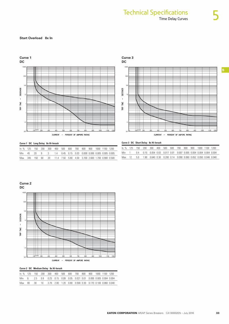
Curve 1 50/60Hz
Start Overload 8 x In (50Hz)
Curve 2 50/60Hz
Curve 3 50/60Hz
Curve 1 50/60Hz Long Delay 8x Hi-Inrush
In. % 125 150 200 300 400 500 600 700 800 900 1000 1100 1200
Min 50 32 10 – 1.5 – 0.5 – 0.02 – 0.006 – 0.005
Max 700 350 90 – 1.5 – 7.0 – 3.00 – 2.000 – 1.000
Curve 2 50/60Hz Medium Delay 8x Hi-Inrush
In. % 125 150 200 300 400 500 600 700 800 900 1000 1100 1200
Min 10 4.5 1.7 0.55 0.25 0.11 0.05 0.025 0.015 0.011 0.01 0.009 0.008
Max 100 50 18 6.00 2.80 1.90 1.50 1.200 0.800 0.410 0.20 0.100 0.050
Curve 3 50/60Hz Short Delay 8x Hi-Inrush
In. % 125 150 200 300 400 500 600 700 800 900 1000 1100 1200
Min 1 0.4 0.15 0.054 0.03 0.017 0.01 0.007 0.005 0.004 0.004 0.004 0.004
Max 12 5.0 1.90 0.640 0.30 0.200 0.14 0.090 0.060 0.050 0.050 0.046 0.040
5
5
EATON CORPORATION AR/AP Series Breakers CA130002EN – July 2016 33
Technical SpecificationsTime Delay Curves
5
5Start Overload 8x In
Curve 1 DC
Curve 3 DC
Curve 1 DC Long Delay 8x Hi-Inrush
In. % 125 150 200 300 400 500 600 700 800 900 1000 1100 1200
Min 45 20 9 3 1.4 0.45 0.15 0.03 0.009 0.006 0.005 0.005 0.005
Max 345 150 60 20 11.4 7.50 5.80 4.50 3.700 2.600 1.700 0.900 0.500
Curve 2 DC
Curve 2 DC Medium Delay 8x Hi-Inrush
In. % 125 150 200 300 400 500 600 700 800 900 1000 1100 1200
Min 6 2.5 0.8 0.25 0.15 0.09 0.05 0.021 0.01 0.006 0.005 0.004 0.004
Max 80 30 10 3.70 2.00 1.20 0.80 0.500 0.30 0.170 0.100 0.060 0.040
Curve 3 DC Short Delay 8x Hi-Inrush
In. % 125 150 200 300 400 500 600 700 800 900 1000 1100 1200
Min 1 0.4 0.15 0.054 0.03 0.017 0.01 0.007 0.005 0.004 0.004 0.004 0.004
Max 12 5.0 1.90 0.640 0.30 0.200 0.14 0.090 0.060 0.052 0.050 0.046 0.040
34 EATON CORPORATION AR/AP Series Breakers CA130002EN – July 2016
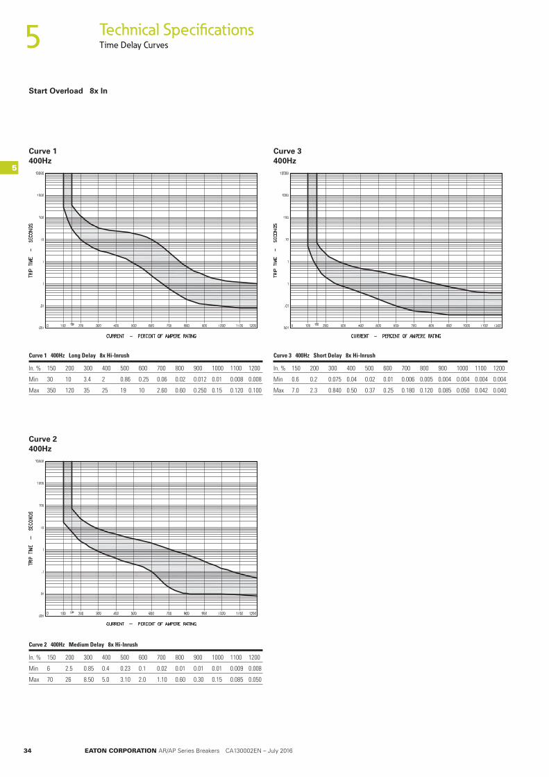
Technical SpecificationsTime Delay Curves
Curve 1 400Hz
Curve 2 400Hz
Curve 3 400Hz
Curve 1 400Hz Long Delay 8x Hi-Inrush
In. % 150 200 300 400 500 600 700 800 900 1000 1100 1200
Min 30 10 3.4 2 0.86 0.25 0.06 0.02 0.012 0.01 0.008 0.008
Max 350 120 35 25 19 10 2.60 0.60 0.250 0.15 0.120 0.100
Curve 2 400Hz Medium Delay 8x Hi-Inrush
In. % 150 200 300 400 500 600 700 800 900 1000 1100 1200
Min 6 2.5 0.85 0.4 0.23 0.1 0.02 0.01 0.01 0.01 0.009 0.008
Max 70 26 8.50 5.0 3.10 2.0 1.10 0.60 0.30 0.15 0.085 0.050
Curve 3 400Hz Short Delay 8x Hi-Inrush
In. % 150 200 300 400 500 600 700 800 900 1000 1100 1200
Min 0.6 0.2 0.075 0.04 0.02 0.01 0.006 0.005 0.004 0.004 0.004 0.004
Max 7.0 2.3 0.840 0.50 0.37 0.25 0.180 0.120 0.085 0.050 0.042 0.040
Start Overload 8x In
5
5

EATON CORPORATION AR/AP Series Breakers CA130002EN – July 2016 35
Technical SpecificationsTime Delay Curves
5
5
COMBINED AC/DC VERSIONS
This type of circuit breaker can be used for 50/60Hz and DC applications. In this case the must trip point is rated at 135%.
Curve 1 50/60Hz – DC
Curve 2 50/60Hz – DC
Curve 3 50/60Hz – DC
Curve 1 50/60Hz/DC Long Delay 8x Hi-Inrush
In. % 135 150 200 300 400 500 600 700 800 900 1000 1100 1200
Min 35 20 9 3 1.4 0.45 0.15 0.03 0.009 0.006 0.005 0.005 0.005
Max 520 350 90 26 15 10.0 7.00 4.80 3.700 2.500 2.000 1.600 1.000
Curve 2 50/60Hz/DC Medium Delay 8x Hi-Inrush
In. % 135 150 200 300 400 500 600 700 800 900 1000 1100 1200
Min 7 4.5 1.7 0.55 0.25 0.11 0.05 0.025 0.015 0.011 0.01 0.009 0.008
Max 80 50 18 6.00 2.80 1.90 1.50 1.200 0.800 0.410 0.20 0.100 0.050
Curve 3 50/60Hz/DC Short Delay 8x Hi-Inrush
In. % 135 150 200 300 400 500 600 700 800 900 1000 1100 1200
Min 0.6 0.4 0.15 0.054 0.03 0.017 0.01 0.007 0.005 0.004 0.004 0.004 0.004
Max 9.0 5.0 1.90 0.640 0.30 0.200 0.14 0.090 0.060 0.052 0.050 0.046 0.040
Start Overload 8x In (50Hz)

36 EATON CORPORATION AR/AP Series Breakers CA130002EN – July 2016
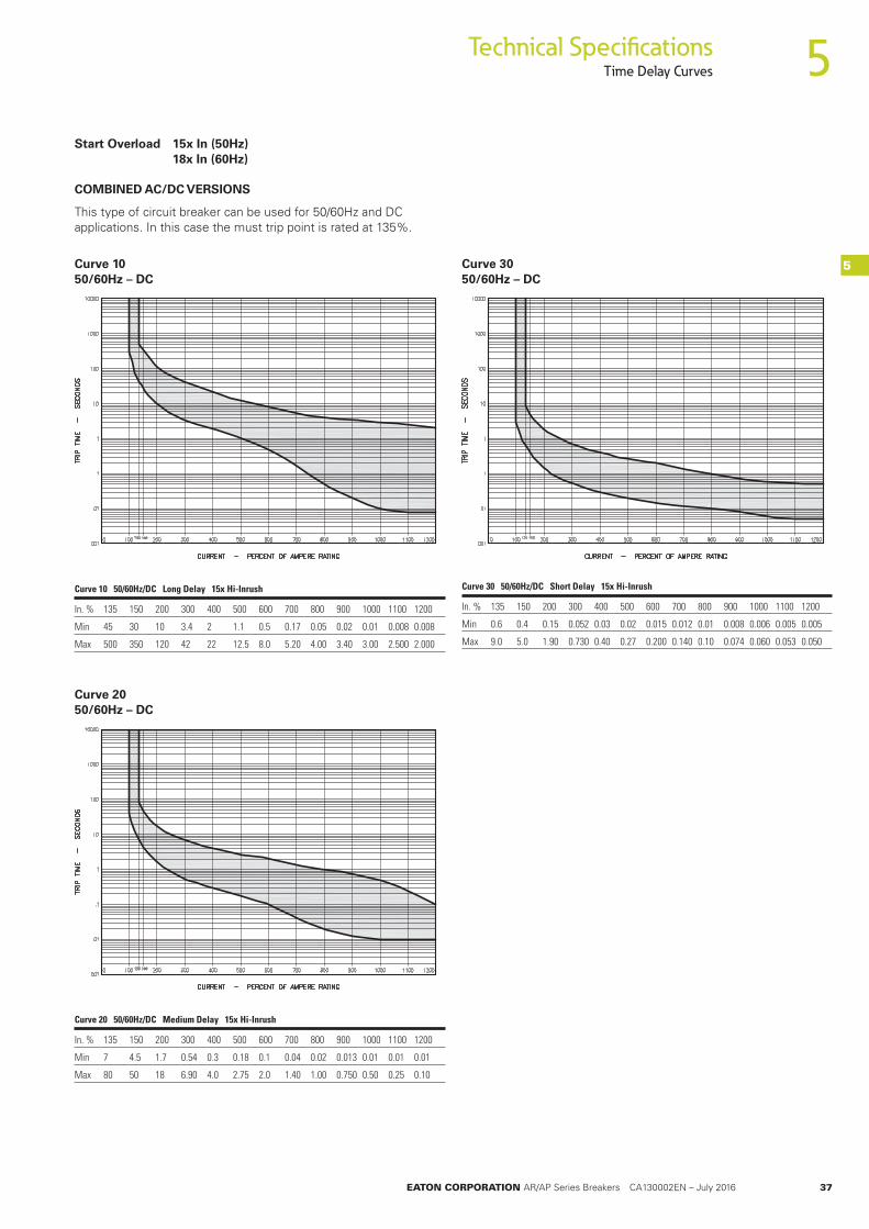
Technical SpecificationsTime Delay Curves
Curve 10 50/60Hz or DC
Curve 20 50/60Hz or DC
Curve 30 50/60Hz or DC
Curve 10 50/60Hz or DC Long Delay 15x Hi-Inrush
In. % 125 150 200 300 400 500 600 700 800 900 1000 1100 1200
Min 60 30 10 3.4 2 1.1 0.5 0.17 0.05 0.02 0.01 0.008 0.008
Max 700 350 120 42 22 12.5 8.0 5.20 4.00 3.40 3.00 2.500 2.000
Curve 20 50/60Hz or DC Medium Delay 15x Hi-Inrush
In. % 125 150 200 300 400 500 600 700 800 900 1000 1100 1200
Min 10 4.5 1.7 0.54 0.3 0.18 0.1 0.04 0.02 0.013 0.01 0.01 0.01
Max 110 50 18 6.90 4.0 2.75 2.0 1.40 1.00 0.750 0.50 0.25 0.10
Curve 30 50/60Hz or DC Short Delay 15x Hi-Inrush
In. % 125 150 200 300 400 500 600 700 800 900 1000 1100 1200
Min 1 0.4 0.15 0.052 0.03 0.02 0.015 0.012 0.01 0.008 0.006 0.005 0.005
Max 12 5.0 1.90 0.730 0.40 0.27 0.200 0.150 0.10 0.074 0.060 0.053 0.050
Start Overload 15x In (50Hz) 18x In (60Hz)
5
5
EATON CORPORATION AR/AP Series Breakers CA130002EN – July 2016 37
Technical SpecificationsTime Delay Curves
5
5
COMBINED AC/DC VERSIONS
This type of circuit breaker can be used for 50/60Hz and DC applications. In this case the must trip point is rated at 135%.
Curve 10 50/60Hz – DC
Curve 20 50/60Hz – DC
Curve 30 50/60Hz – DC
Curve 10 50/60Hz/DC Long Delay 15x Hi-Inrush
In. % 135 150 200 300 400 500 600 700 800 900 1000 1100 1200
Min 45 30 10 3.4 2 1.1 0.5 0.17 0.05 0.02 0.01 0.008 0.008
Max 500 350 120 42 22 12.5 8.0 5.20 4.00 3.40 3.00 2.500 2.000
Curve 20 50/60Hz/DC Medium Delay 15x Hi-Inrush
In. % 135 150 200 300 400 500 600 700 800 900 1000 1100 1200
Min 7 4.5 1.7 0.54 0.3 0.18 0.1 0.04 0.02 0.013 0.01 0.01 0.01
Max 80 50 18 6.90 4.0 2.75 2.0 1.40 1.00 0.750 0.50 0.25 0.10
Curve 30 50/60Hz/DC Short Delay 15x Hi-Inrush
In. % 135 150 200 300 400 500 600 700 800 900 1000 1100 1200
Min 0.6 0.4 0.15 0.052 0.03 0.02 0.015 0.012 0.01 0.008 0.006 0.005 0.005
Max 9.0 5.0 1.90 0.730 0.40 0.27 0.200 0.140 0.10 0.074 0.060 0.053 0.050
Start Overload 15x In (50Hz) 18x In (60Hz)
38 EATON CORPORATION AR/AP Series Breakers CA130002EN – July 2016
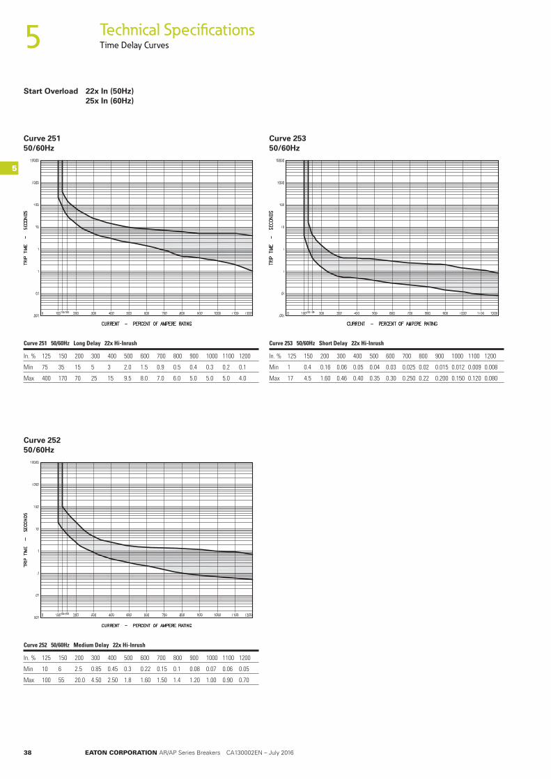
Technical SpecificationsTime Delay Curves
Curve 251 50/60Hz
Curve 252 50/60Hz
Curve 253 50/60Hz
Curve 251 50/60Hz Long Delay 22x Hi-Inrush
In. % 125 150 200 300 400 500 600 700 800 900 1000 1100 1200
Min 75 35 15 5 3 2.0 1.5 0.9 0.5 0.4 0.3 0.2 0.1
Max 400 170 70 25 15 9.5 8.0 7.0 6.0 5.0 5.0 5.0 4.0
Curve 252 50/60Hz Medium Delay 22x Hi-Inrush
In. % 125 150 200 300 400 500 600 700 800 900 1000 1100 1200
Min 10 6 2.5 0.85 0.45 0.3 0.22 0.15 0.1 0.08 0.07 0.06 0.05
Max 100 55 20.0 4.50 2.50 1.8 1.60 1.50 1.4 1.20 1.00 0.90 0.70
Curve 253 50/60Hz Short Delay 22x Hi-Inrush
In. % 125 150 200 300 400 500 600 700 800 900 1000 1100 1200
Min 1 0.4 0.16 0.06 0.05 0.04 0.03 0.025 0.02 0.015 0.012 0.009 0.008
Max 17 4.5 1.60 0.46 0.40 0.35 0.30 0.250 0.22 0.200 0.150 0.120 0.080
Start Overload 22x In (50Hz) 25x In (60Hz)
5
5
EATON CORPORATION AR/AP Series Breakers CA130002EN – July 2016 39
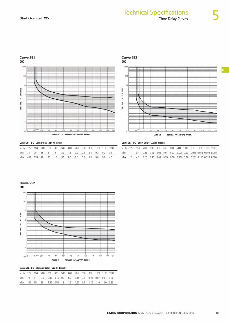
Technical SpecificationsTime Delay Curves
5
5
Curve 251 DC
Curve 252 DC
Curve 253 DC
Curve 251 DC Long Delay 22x Hi-Inrush
In. % 125 150 200 300 400 500 600 700 800 900 1000 1100 1200
Min 75 35 15 5 3 2.0 1.5 0.9 0.5 0.4 0.3 0.2 0.1
Max 400 170 70 25 15 9.5 8.0 7.0 6.0 5.0 5.0 5.0 4.0
Curve 252 DC Medium Delay 22x Hi-Inrush
In. % 125 150 200 300 400 500 600 700 800 900 1000 1100 1200
Min 10 6 2.5 0.85 0.45 0.3 0.2 0.15 0.1 0.08 0.07 0.07 0.06
Max 100 55 20 4.50 2.50 1.8 1.6 1.50 1.4 1.20 1.10 1.00 0.90
Curve 253 DC Short Delay 22x Hi-Inrush
In. % 125 150 200 300 400 500 600 700 800 900 1000 1100 1200
Min 1 0.4 0.16 0.06 0.05 0.04 0.03 0.025 0.02 0.015 0.012 0.009 0.008
Max 17 4.5 1.60 0.46 0.40 0.35 0.30 0.250 0.22 0.200 0.150 0.120 0.080
Start Overload 22x In
40 EATON CORPORATION AR/AP Series Breakers CA130002EN – July 2016
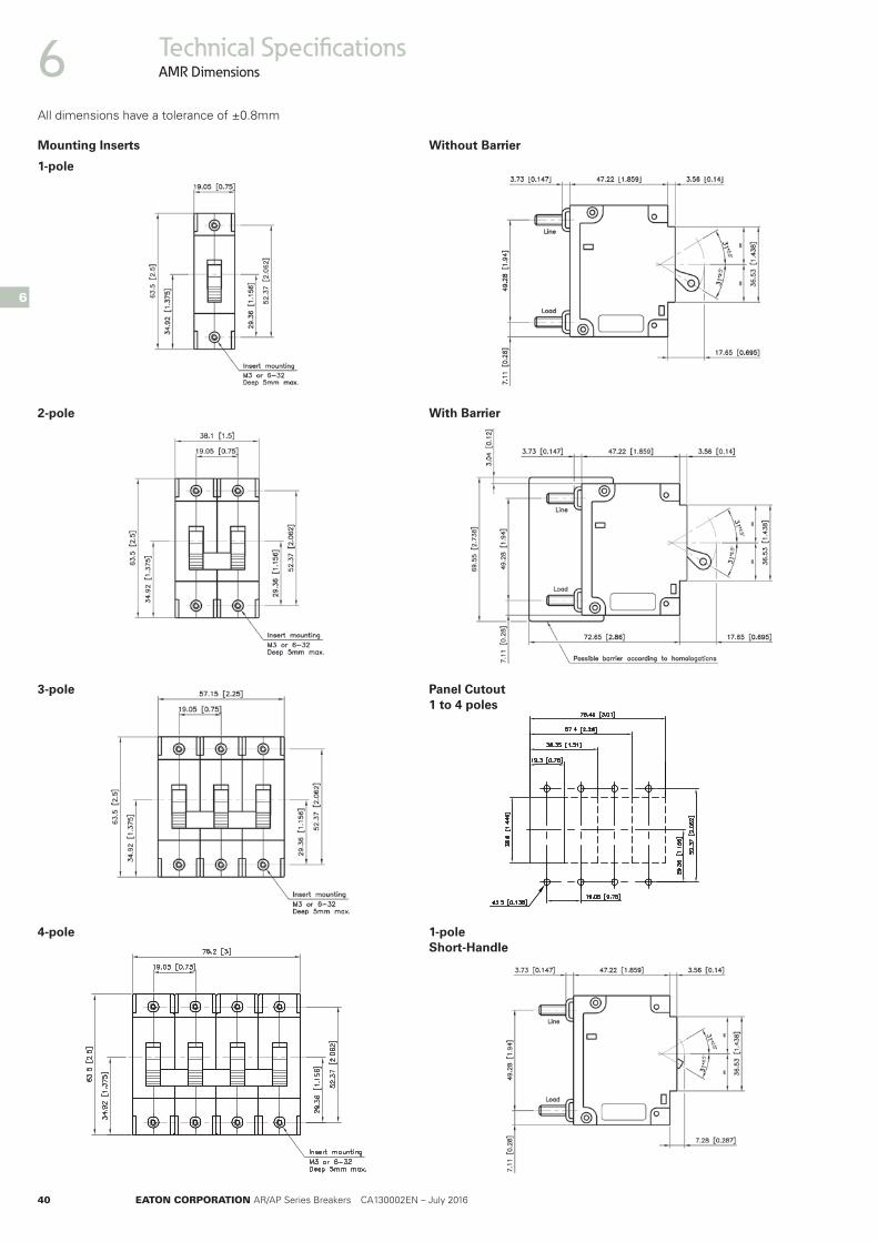
2-pole
3-pole
4-pole
Without Barrier
1-pole
With Barrier
Panel Cutout 1 to 4 poles
1-pole Short-Handle
Mounting Inserts
Technical SpecificationsAMR Dimensions6
6
All dimensions have a tolerance of ±0.8mm
EATON CORPORATION AR/AP Series Breakers CA130002EN – July 2016 41
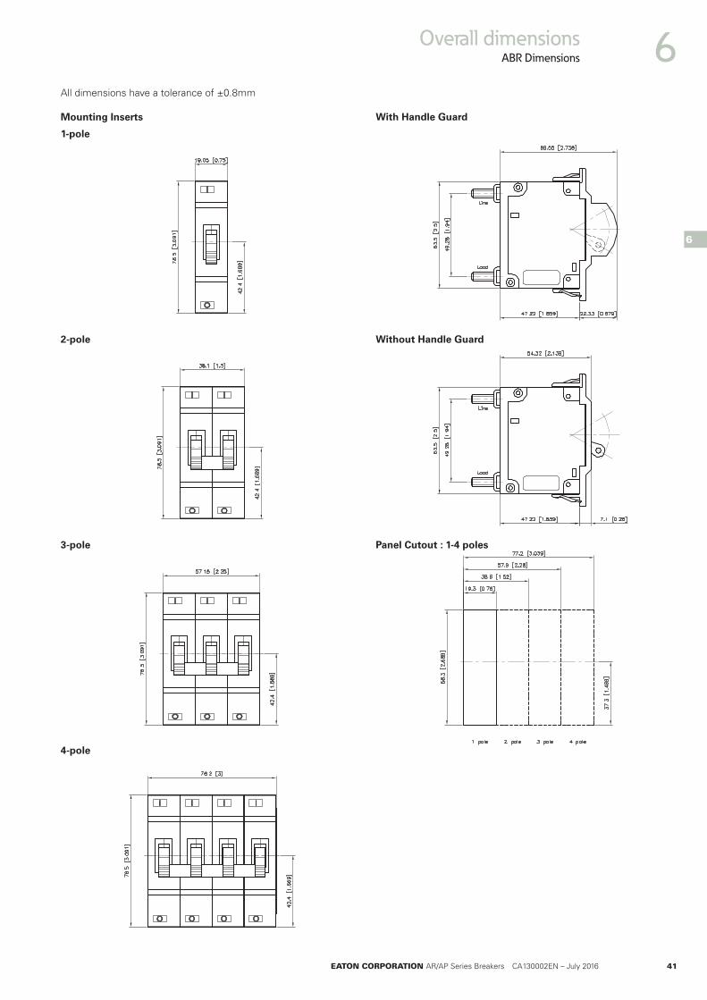
Overall dimensionsABR Dimensions 6
1-pole
2-pole Without Handle Guard
Panel Cutout : 1-4 poles3-pole
4-pole
With Handle Guard
Mounting Inserts
All dimensions have a tolerance of ±0.8mm
6
42 EATON CORPORATION AR/AP Series Breakers CA130002EN – July 2016
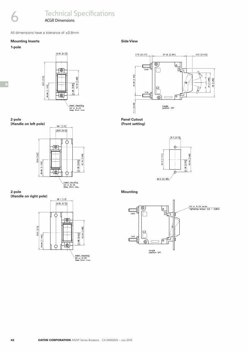
Technical SpecificationsACGR Dimensions
1-pole
2-pole (Handle on left pole)
2-pole (Handle on right pole)
Side View
Mounting
Panel Cutout (Front setting)
Mounting Inserts
6All dimensions have a tolerance of ±0.8mm
6

EATON CORPORATION AR/AP Series Breakers CA130002EN – July 2016 43
Overall dimensionsACWR Dimensions 6
1-pole
2-pole (Handle on left pole)
2-pole (Handle on right pole)
Mounting
Panel Cutout (Front setting)
Mounting Inserts Side View
All dimensions have a tolerance of ±0.8mm
6
44 EATON CORPORATION AR/AP Series Breakers CA130002EN – July 2016
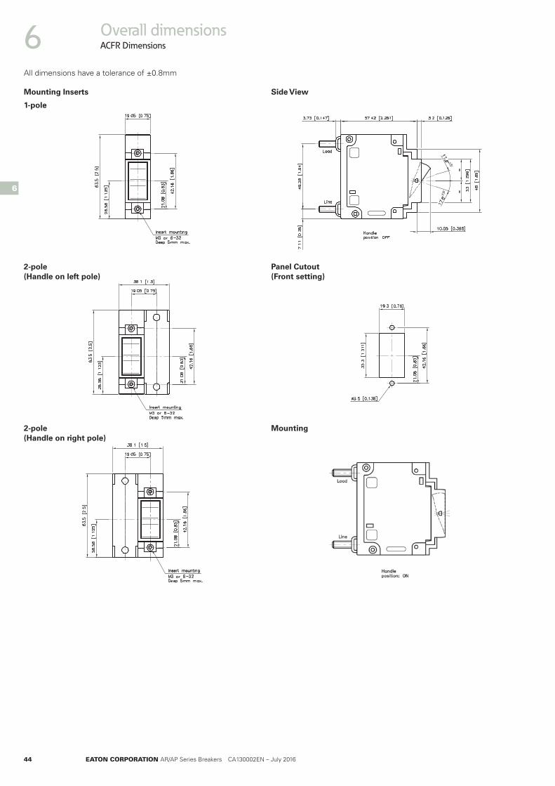
Overall dimensionsACFR Dimensions
1-pole
2-pole (Handle on left pole)
2-pole (Handle on right pole)
Mounting
Panel Cutout (Front setting)
Mounting Inserts Side View
6
6
All dimensions have a tolerance of ±0.8mm

EATON CORPORATION AR/AP Series Breakers CA130002EN – July 2016 45
Overall dimensionsAER Dimensions 6
6
1-pole
2-pole (Handle on left pole)
2-pole (Handle on right pole)
Panel Cutout (Front setting)
3-pole AER mounting
Metal Short Handle
Mounting Inserts Metal Long Handle
All dimensions have a tolerance of ±0.8mm

46 EATON CORPORATION AR/AP Series Breakers CA130002EN – July 2016
Overall dimensionsALR Dimensions6
6
1-pole
2-pole (Handle on left pole)
Single Auxiliary Switch
2-pole (Handle on right pole)
3-pole
Panel Cutout
Mounting Inserts Without Auxiliary Switch
All dimensions have a tolerance of ±0.8mm
EATON CORPORATION AR/AP Series Breakers CA130002EN – July 2016 47
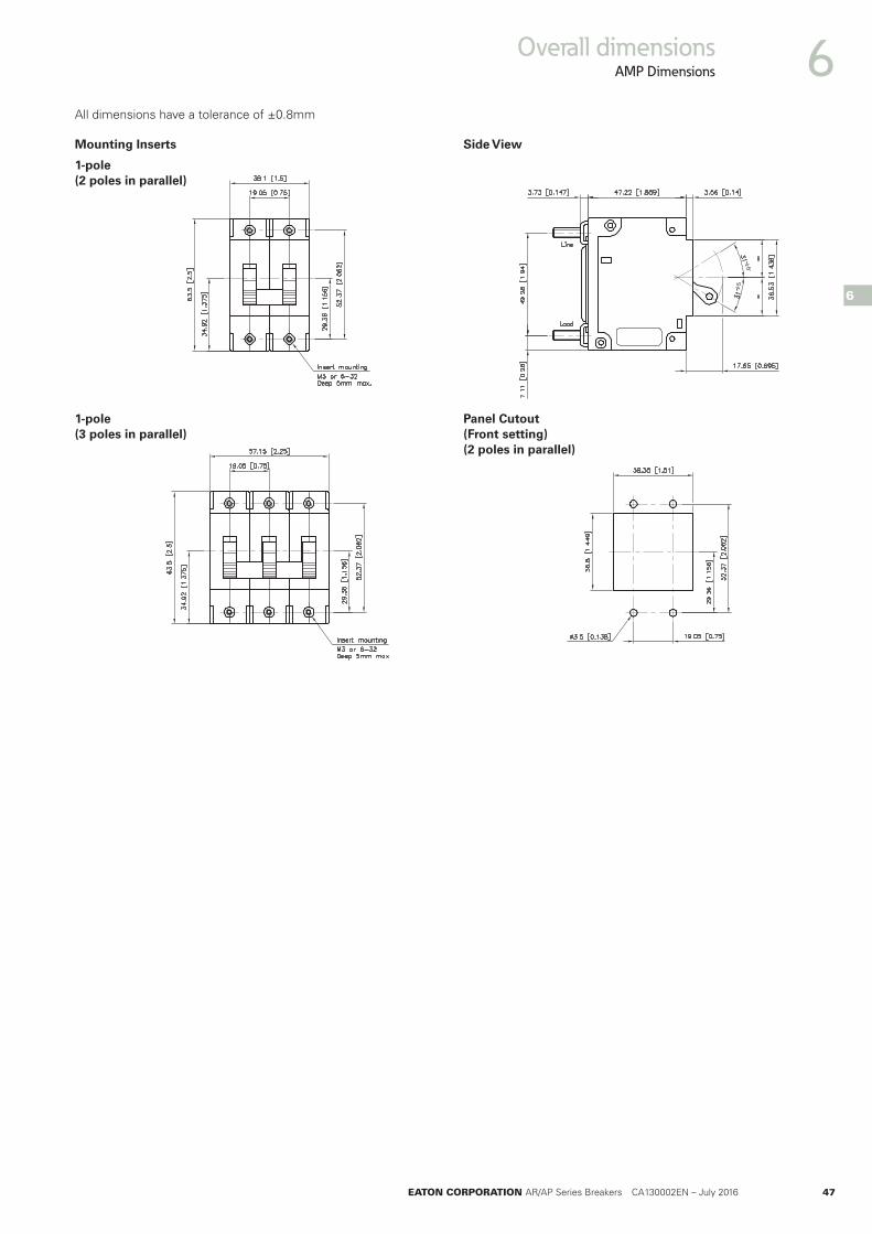
Overall dimensionsAMP Dimensions 6
6
1-pole (2 poles in parallel)
1-pole (3 poles in parallel)
Panel Cutout (Front setting) (2 poles in parallel)
Mounting Inserts Side View
All dimensions have a tolerance of ±0.8mm
48 EATON CORPORATION AR/AP Series Breakers CA130002EN – July 2016
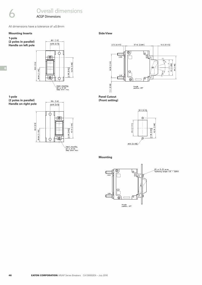
1-pole (2 poles in parallel) Handle on left pole
1-pole (2 poles in parallel) Handle on right pole
Panel Cutout (Front setting)
Mounting
Mounting Inserts Side View
Overall dimensionsACGP Dimensions6
6
All dimensions have a tolerance of ±0.8mm
EATON CORPORATION AR/AP Series Breakers CA130002EN – July 2016 49
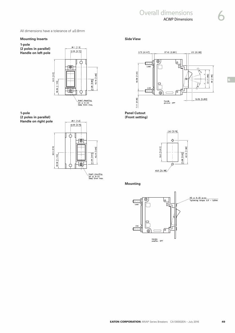
Overall dimensionsACWP Dimensions 6
6
Mounting
1-pole (2 poles in parallel) Handle on left pole
1-pole (2 poles in parallel) Handle on right pole
Panel Cutout (Front setting)
Mounting Inserts Side View
All dimensions have a tolerance of ±0.8mm

50 EATON CORPORATION AR/AP Series Breakers CA130002EN – July 2016
1-pole (2 poles in parallel) Handle on left pole
1-pole (2 poles in parallel) Handle on right pole
Panel Cutout (Front setting)
Mounting
Mounting Inserts Side view (Flat rocker version)
Overall dimensionsACP Dimensions6
6
All dimensions have a tolerance of ±0.8mm

EATON CORPORATION AR/AP Series Breakers CA130002EN – July 2016 51
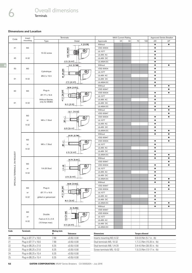
Overall dimensionsTerminals 6
6
PARA001070552slavorppAliateDepyT
Without • •VDE 60934 •UL1077 •UL489 AC •UL489 DC •UL489A DC •Without • •VDE 60947 •VDE 60934 • •UL1077 •UL489 AC •UL489 DC •UL489A DC • •Without • •VDE 60934 •UL1077 •UL489 AC •UL489 DC •UL489A DC •Without • •VDE 60947 •VDE 60934 • •UL1077 •UL489 AC •UL489 DC •UL489A DC • •Without • •VDE 60947 •VDE 60934 • •UL1077 •UL489 AC •UL489 DC •UL489A DC • •Without • •VDE 60947 •VDE 60934 • •UL1077 •UL489 AC •UL489 DC •UL489A DC • •Without • •VDE 60947 •VDE 60934 • •UL1077 •UL489 AC •UL489 DC •UL489A DC • •Without • •VDE 60934 •UL1077 •UL489 AC •UL489 DC •UL489A DC •Without • •VDE 60934 •UL1077 •UL489 AC •UL489 DC •UL489A DC •
07
08
10-32 Stud
M5 x 0.8 Stud
6-32
09
MAX Current RatingTerminals
10
13
15
14
16
20
21
22
23
24
25
30
31
40
44
6-32
M3
M3
M3
6-32
M3
6-32
M3
1/4-20 Stud
M6 x 1 Stud
10-32 Stud
M5 x 0.8 Stud
1/4-20 Stud
M6 x 1 Stud
Plug-in
Ø7.77 x 16.6
Plug-in
Ø6.25 x 15.4
M3
6-32
InsertmountingCode
Approved Series Breaker
6-32
M3
6-32
Plug-in
Ø6.25 x 21.6
Fuse
clip
Ø6.
35
M5 screw
Dimensions and Location
52 EATON CORPORATION AR/AP Series Breakers CA130002EN – July 2016
Overall dimensionsTerminals6
6
PARA001070552slavorppAliateDepyT
Without • •VDE 60934 •UL1077 •UL489 AC •UL489 DC •UL489A DC •Without • •VDE 60934 •UL1077 •UL489 AC •UL489 DC •UL489A DC •Without • •VDE 60947 •VDE 60934 • •UL1077 •UL489 AC •UL489 DC •UL489A DC • •Without • •VDE 60947 •VDE 60934 • •UL1077 •UL489 AC •UL489 DC •UL489A DC • •Without • •VDE 60947 •VDE 60934 • •UL1077 •UL489 AC •UL489 DC •UL489A DC • •Without • •VDE 60947 •VDE 60934 • •UL1077 •UL489 AC •UL489 DC •UL489A DC • •Without • •VDE 60947 •VDE 60934 • •UL1077 •UL489 AC •UL489 DC •UL489A DC • •Without • •VDE 60947
VDE 60934
UL1077
UL489 AC
UL489 DC
UL489A DC
Insert
mounting
41
45
50
Code
51
60
61
M3
M3
6-32
10-32 screw
Cylindrique
Ø6.0 x 19.5
Plug-in
Ø7.77 x 16.6
Without Barrier,
only for MDBS
6-32
Terminals
M3
6-32
M3
or
6-32
M3
or
6-32
M6 x 1 Stud
M3
or
6-32
M6 x 1 Stud
MAX Current Rating Approved Series Breaker
M3
or
6-32
1/4-28 Stud
SP
EC
IALS
TE
RM
INA
LS
, O
N R
EQ
UE
ST
M3
or
6-32
Double
Fast-on 6.3 x 0.8
(10 Amps max)
Plug-in
Ø7.77 x 16.6
gilded or galvanized
Dimensions Torque allowed
Inserts mounting M3; 6-32 0.6-0.8 Nm (5-7 in. -lb)Stud terminals M5; 10-32 1.7-2.3 Nm (15-20 in. -lb)Stud terminals M6; 1/4-20 3.4-4.0 Nm (30-35 in. -lb)Screw terminals M5; 10-32 1.5-2.0 Nm (13-17 in. -lb)
Code Terminals Mating hole Ø Tolerance
20 Plug-in Ø7.77 x 16.6 7.90 +0.05/-0.0021 Plug-in Ø7.77 x 16.6 7.90 +0.05/-0.0022 Plug-in Ø6.25 x 21.6 6.35 +0.05/-0.0023 Plug-in Ø6.25 x 21.6 6.35 +0.05/-0.0024 Plug-in Ø6.25 x 15.4 6.35 +0.05/-0.0025 Plug-in Ø6.25 x 15.4 6.35 +0.05/-0.00
Dimensions and Location
EATON CORPORATION AR/AP Series Breakers CA130002EN – July 2016 53
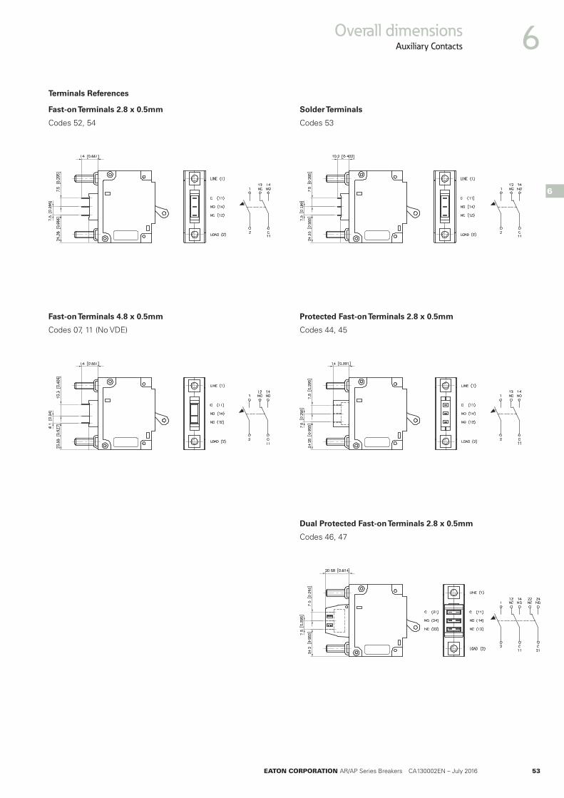
Overall dimensionsAuxiliary Contacts 6
6
Codes 52, 54
Codes 07, 11 (No VDE) Codes 44, 45
Codes 53
Codes 46, 47
Fast-on Terminals 2.8 x 0.5mm
Fast-on Terminals 4.8 x 0.5mm Protected Fast-on Terminals 2.8 x 0.5mm
Solder Terminals
Dual Protected Fast-on Terminals 2.8 x 0.5mm
Terminals References

54 EATON CORPORATION AR/AP Series Breakers CA130002EN – July 2016
Overall dimensionsMid-Trip Alarm Switch6
6
AMR ABR
Test Button Option
Off Position On Position MID-TRIP Position (Electrical Trip)
Configuration available with double Alarm switch (2HK)
Test Button Option
Types AMA, AMB, AMM, AMN ABA, ABB, ABM, ABN
Conventional circuit breakers have two handle positions: ON and OFF.
The MID-TRIP ALARM-SWITCH versions have three positions: ON, OFF, ELECTRICAL OFF (MID-TRIP position) which allows immediate visual identification of an electrically tripped circuit breaker (handle moves to the MID-TRIP position).
The optional integrated test button offers the advantage to verify the electrical trip functions without electrically simulating an overcurrent.
Adding auxiliary contacts changes the AMR or ABR MID-TRIP breakers into a sophisticated ALARM-SWITCH that can also indicate when the main contacts have been electrically opened.

All of the above are trademarks of Eaton Corporation or its affiliates. Eaton has a license to use the Westinghouse brand name in Asia Pacific. ©2012 Eaton Corporation.
1874 1886 19111893 19831962 19891984 19991976 1977190819061899 1963 19671934
The power of fusion.
There’s a certain energy at Eaton. It’s the power of uniting some of the world’s most respected names to build a brand you can trust to meet every power management need. The energy created supports our commitment to powering business worldwide.
Eaton is dedicated to ensuring that reliable, efficient and safe power is available when it’s needed most. With unparalleled knowledge of electrical power management across industries, experts at Eaton deliver customized, integrated solutions to solve our customers’ most critical challenges. Eaton.com/Electrical.
Changes to the products, to the information contained in this document, and to prices are re-served; so are errors and omissions. Only order confirmations and technical documentation by Eaton is binding. Photos and pictures also do not warrant a specific layout or functionality. Their use in whatever form is subject to prior approval by Eaton. The terms and Conditions of Eaton apply, as referenced on Eaton internet pages and Eaton order confirmations.
Our focus is on delivering the right solution for the application. But, decision makers demand more than just innovative products. They turn to Eaton for an unwavering commitment to personal support that makes customer success a top priority.
For more information, visit www.eaton.eu/electrical
To contact an Eaton salespersonor local distributor/agent, please visitwww.eaton.eu/electrical/customersupport
Local Distributor/agent
Follow us on social media to get the latest product and support information.
For more information, visit www.eaton.eu/electrical or send your request to [email protected]
Eaton Industries Manufacturing GmbHEMEA Headquarters7 Route de la Longeraie1110 MorgesSwitzerland
© 2016 Eaton CorporationAll Rights ReservedAll other trademarks are propertyof their respective owners. Publication number CA130002EN


