
2. Parts and Functions
1. Introductions 3. Terminal Description
-1- -2- -3-
• +12V: 12VDC power output.• LK-: power ground.• LK+: common contact of the relay.• NO.: normally open contact of the relay• EB+: exit button positive connection port.• EB-: exit button negative connection port.• JP-LK: for electronic lock safety type setting(refer to door lock connections).• SET : DIP switches for system configurations.• CN/KMB: call button module connection port.• CN/T-COIL: reserved.• CN/FUN: touch sensor keypad module or TFT display module connection
CN
-LK
JP-LK
+12V
LK-
LK+
NO
EB
-
EB
+
SE
T
12V
TX1
RX
1G
ND
RX
3TX
3G
ND
5CL
GN
D5D
AR
ST
INT
GN
D12
VC
LKD
AT
STR
C2
C1
CTR
GN
DG
ND
VIO
PO
W
WG
0W
G1
GN
D12V
CN/KMB CN/T-COIL
CN/FUN CN/WGNL1 L2
1 2 3 4 5 6
ON DIP
DavidCalo
5. Mounting
name paper
L1 L2
1 2 3 4 5 6
ON DIP
308
mm
123 mm
RF CARD
Camera LensSpeaker
Night View LED
ID Card WindowStatus Indicator
Microphone
Nameplate
LED Indicator
Call button
Mounting box for flush mounted
Rainy cover for surface mounted
Connection port
Surface mounted
298.
5 m
m
114.5 mm
45 mm
This manual is a guide for quick installation. For more detailed instructions, please refer to the DT system technical guide.
The door station provides means of calling and communication to the internal video handsets, when in communication control of a door locking device is available. The modular design of the MW Series provides high flexibility allowing various panel configurations for example a video entry module and a card reader module can be assembled with call buttons: this example allows users to swipe cards to open the door. For the card type, please refer to DT system technical guide.
A B
Note: Keys A and key B will not be seen on the panel as they are hidden. For information regarding activating key A and key B, please refer to Part 7.
4. Name Label
Press down and move to the left or right to open the transparent nameplate cover. Then insert the name paper and replace the cover. Please note that the double row button panel can be opened in both directions, the single row button panel can only be opened to the right side.
Semi-flush mounted
port.• CN/WGN: card reader module connection port.• Bus(L1,L2): non-polarity bus line, connect to PC6.
Note: Keypad and TFT display modules are also available, please refer to DT system technical guide.
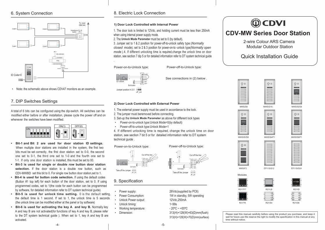
Quick Installation Guide
8. Electric Lock Connection
9. Specification
Please read this manual carefully before using the product you purchase, and keep it well for future use.We reserve the right to modify the specification in this manual at any time without notice.
RF CARD
RF CARD
R21/TFT R21/LB R21/ID
R21/TK R21/S4 R21/D8
1 2 3
4 5 6 0
7 8 #9
*
Modules
6. System Connection
7. DIP Switches Settings
ON(1)
=
OFF(0)
=ONON
ON
1 2 3 4 5 6
1) Door Lock Controlled with Internal Power
2) Door Lock Controlled with External Power
• Power-on-to-unlock type:Unlock Mode=0(by default)• Power-off-to-unlock type:Unlock Mode=1
JP_LK
12V 300mA
Exit button
Jumper position in 2-3
+
-+12VLK - LK+N.O.EB-EB+
1 2 3
Power-on-to-Unlock type:
Power-off-to-Unlock type:
+
+
-
-+12VLK - (GND)LK+(COM)N.O.EB-EB+
Take off the JumperJP_LK
Cut off the line
1 2 3
Exit button
+12VLK - (GND)LK+(COM)N.O.EB-EB+
Take off the Jumper
+
+
-
-
JP_LK
Cut off the line
1 2 3
Exit button
Code=0
OFF ON
DBC4
A
A B
C D
Impedance switch
To next DBC4A
100~240VAC
BUS(IM) BUS(DS)
PC6
AC~
Code=2
Code=1
Code=3
RF CARD
BUS(IM) BUS(DS)
ID Code=0
-4- -5-
313(H)×128(W)×70(D)mm(surface)
• Note: the schematic above shows CDV47 monitors as an example.
A total of 6 bits can be configured using the dip-switch. All switches can be modified either before or after installation, please cycle the power off and on whenever the switches have been modified.
• Bit-6 is used for activating the key A and key B. Normally key A and key B are not activated(for functions of key A and key B, please refer to the DT system technical guide ). When set to 1, key A and key B are activated.
• Bit-5 is used for unlock time setting. 0 is the default setting,the default time is 1 second. If set to 1, the unlock time is 5 seconds (the unlock time can be modified either at the panel or by software)
• Bit-4 is used for button code selection. If using the default codes (Button #1 top left) for each button of the door station, set to 0. If using programmed codes, set to 1(the code for each button can be programmed by software, for detailed information refer to DT system technical guide)
1. The external power supply must be used in accordance to the lock.2. The jumper must beremoved before connecting.3. Set-up the Unlock Mode Parameter as above for different lock types
MWS/S8 MWS/D16 MWS/ID/S4
MWS/ID/D8 MWS/S4/F1 MWS/D8/F1
MWS/F2 EP11S/S12 EP11S/D24
4. If different unlocking time is required, change the unlock time on door station, see section 7 bit 5 or for detailed information refer to DT system technical guide .
Power-on-to-Unlock type:
1. The door lock is limited to 12Vdc, and holding current must be less than 250mA when using internal power supply mode.2. The Unlock Mode Parameter must be set to 0 (by default).3. Jumper set to 1 & 2 position for power-off-to-unlock safety type (Normally closed mode); set to 2 & 3 position for power-on-to -unlock type(Normally open mode ). 4. If different unlocking time is required,change the unlock time on door station, see section 7 dip 5 or for detailed information refer to DT system technical guide .
Power-off-to-Unlock type:
See connections in (2) below .
• Power supply: 26Vdc(supplied by PC6)• Power Consumption: 1W in standby, 5W operating• Unlock Power output: 12Vdc,250mA• Unlock timing: 1~99s• Working temperature: - 20ºC ~ +55ºC• Dimension: 313(H)×128(W)×63(D)mm(flush)
• Bit-1 and Bit 2 are used for door station ID settings. When multiple door stations are installed in the system, the first two bits must be set correctly, the first door station set to 0-0, the second
• Bit-3 is used for single or double row button door station selection. If the door station is a double row button, such as CDV-MW8ID set this bit to 0. For single row button door station,set to 1.
one set to 0-1, the third one set to 1-0 and the fourth one set to 1-1. If only one door station is installed, this must be set to 00.
CDV-MW Series Door Station2-wire Colour ARS Camera
Modular Outdoor Station


