4" SIDE PORT
PRESSURE VESSEL
TECHNICAL
MANUAL
January 2013
I January 2013 1st Edition
Introduction
BEL, founded in 1966, specializes in the design and manufacture of a variety of
products made from advanced composite materials. With over 40 years of experience,
the company has developed and mastered the innovative technologies necessary to
manufacture the highest quality composite products. Combining innovation,
technology, responsibility and dedication, our goal is to become the leader in
providing commercial and industrial composite vessels for our clients needs.
BEL pressure vessels are manufactured from filament wound fiber reinforced plastic
(FRP), wound over precision mandrels, using a superior epoxy resin, which results in
the ultimate combination of physical strength and an ultra smooth inside surface.
Vessels are tested according to the requirements of ASME code section X, the
internationally recognized standard for pressure vessel construction.
BEL holds ISO 9001 quality systems certification, and its quality assurance is also
approved for in-house final inspection by many of its customers.
The BEL family of pressure vessels is designed to be used as housings for all 4'' ,8''
,9'' and 16'' spiral-wound Reverse Osmosis (RO), Nanofiltration (NF) and Ultra
filtration (UF) membrane elements.
The pressure vessels are manufactured in different configurations, according to the
required operating pressures, filtration type, and piping layout. In order to enhance
interchangeability and facilitate the use and maintenance of the vessels, the utilization
of identical parts and sub-assemblies has been maximized throughout the design of
the vessel. For better performance and longer service life, each model is manufactured
from the highest quality and highest performing materials of construction.
II January 2013 1st Edition
Table of contents
Introduction ............................................................................................................................ I
Chapter 1- Safety precautions ...............................................................................................1
Chapter 2 - Installations notes ................................................................................................2
Chapter 3 - component list......................................................................................................3
3.1 BEL 4" pressure vessel - 300/450 PSI side port assembly ....................................3
3.2 BEL 4" pressure vessel - 600/1000/1200 PSI side port assembly .......................4
Chapter 4 - Maintenance ........................................................................................................5
4.1 Head assembly .....................................................................................................5
4.1.1 - BEL 4" pressure vessel 300/450 PSI ...................................................6
4.1.2 - BEL 4" pressure vessel 600/1000/1200 .............................................7
4.2 - Head disassembly ..............................................................................................8
4.3 - Visual inspection ...............................................................................................8
4.3.1 Component inspection ........................................................................8
4.3.1 Vessel inspection ................................................................................8
4.4 - Loading the membrane element .......................................................................9
Appendixes ...........................................................................................................................10
Appendixe 1 - Shimming procedure ........................................................................10
Appendixe 2 - BEL puller for 4" pressure vessel ......................................................12
Appendixe 3 - O-Ring replacement and scratches treatment procedure ................14
III January 2013 1st Edition
Table list
Table 2.1 Victaulic maximum offsets ......................................................................................2
Table 3.1 BEL 4" 300/450 PSI component list..........................................................................3
Table 3.2 - BEL 4" 600/1000/1200 PSI components list ..........................................................4
Figures list
Fig 3.1 - BEL 4" 300/450 PSI head assembly ............................... ...........................................3
Fig 3.2 - BEL 4" 600/1000/1200 PSI head assembly ................................................................4
Fig 4.1 - BEL 4" pressure vessel head components -350/450 PSI ............................................5
Fig 4.2 - BEL 4" pressure vessel head components - 600/1000/1200 PSI ................................5
/14 January 2013 1st Edition1
Chapter 1- Safety precautions
i. BEL pressure vessels are designed for high pressure operations. Improper
installation, operation service or maintenance may cause severe damage to
property, physical injury or death.
ii. BEL pressure vessels are designed for water treatment only.
iii. PRESSURE AND TEMPERATURE DESIGN LIMITS - Operation of a vessel
outside the design limits will make void the warranty and may result in vessel
fatigue with possible eventual explosive head failure. Although each vessel is
tested at 110% of the design pressure LONG-TERM OPERATION ABOVE
DESIGN PRESSURE MUST BE PREVENTED. Permeate port pressure MUST
NOT EXCEED 125 psi (8.6 bar).
Vessels should NOT BE CONTINUOUSLY OPERATED AT
TEMPERATURES ABOVE 120°. (49° C).
iv. The pressure vessel should not be use as a support. Piping manifolds and other
fittings should be properly designed system framework. OPERATING
PERSONNEL SHOULD BE DISCOURAGED FROM APPLYING UNDUE
FORCE TO ANY FITTINGS CONNECTED DIRECTLY TO A PRESSURE
VESSEL.
v. Only qualified mechanics, experienced in working with high pressure hydraulic
systems, should be allowed to disassemble or assemble the vessel.
vi. Regularly inspect the system so as to ensure that the various components have not
deteriorated or been damaged. Replace any faulty component, make sure the reason
for the fault has been found and fixed as well.
vii. Make sure that vessels and associated pipe systems are fully depressurized before
attempting any service or maintenance operation.
viii. Be careful not to scratch the inside wall of the shell, especially at the inner sealing
area near the groove.
ix. Corroded parts may cause difficulties in removing the head or other components.
Do not try to force remove components before all visible signs of corrosion have
been eliminated.
x. Never attempt to repair or disassemble the feed/concentrate port in a side port
vessel without consulting BEL.
xi. Inspect end closures regularly; replace components that have deteriorated and
correct causes of corrosion.
xii. Do not tolerate Leaks, or allow end closures to be routinely wetted in any way.
/14 January 2013 1st Edition2
Chapter 2 - Installation notes
2.1 Provide adequate room for serving at both ends of vessel. Elements are installed
from the upstream end, pushed through towards the downstream end and
eventually removed from the downstream end.
2.2 Make sure that the vessel is horizontally installed on support saddles.
2.3 The vessels must not be rigidly clamped in place, mounting design must allow for
both radial and axial expansion (typically up to 0.5 mm radial and up to 2-3 mm
axial). Restriction can result in damage to the vessel and other system components.
2.4 Straps should be tightened enough to hold the vessel onto the support pads, but
never so tightly as to restrict expansion.
2.5 A flexible piping connection should be provided in order to prevent unwanted
loads transfer from the manifolds to the permeate connection and to permit
decoupling the header from the vessel.
The recommended permeate port connection is a U-bend pipe with flexible
connections at each end.
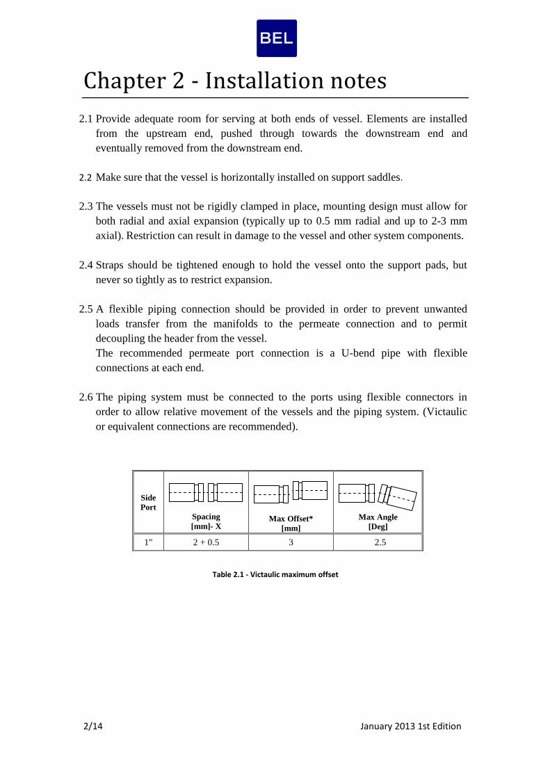
2.6 The piping system must be connected to the ports using flexible connectors in
order to allow relative movement of the vessels and the piping system. (Victaulic
or equivalent connections are recommended).
Table 2.1 - Victaulic maximum offset
Max Angle
[Deg]
Max Offset*
[mm]
Spacing
[mm]- X
Side
Port
2.5 3 2 + 0.5 1"

/14 January 2013 1st Edition3
Chapter 3 - Component list
3.1 BEL 4" pressure vessel - 300/450 psi side port assembly
Fig 3.1 - BEL 4" 300/450 PSI head assembly (ends are identical)
MATERIAL DESCRIPTION QTY PART
NUMBER ITEM
Vessel
Glass/Epoxy Body of pressure vessel 1 41300-1* 1
Head assembly
Stainless steel Retaining ring 2 55410208 2
Engineering plastic Base plate 2 003-400-0005 3
EPDM Seal for base plate 2 55412360 4
EPDM Seal for adapter 2 55412367 5
Engineering plastic Disk spacer 0-6 55412377 6
EPDM Membrane seal 2 As required 7
Engineering plastic Adapter 2 As required 8
Feed/Concentrate port assembly
Stainless steel F/C port 1" 1-4 009-106-0450 9
EPDM Seal for F/C port 1-4 014-100-0505 10
Stainless steel Disk for F/C port 1-4 006-112-1202 11
Stainless steel Retaining ring 2-8 011-100-1202 12
Vessel support parts - optional -
Stainless steel Strap assembly 2 55410246 13**
Engineering plastic Saddle 2-3 55410352 14**
* For working pressures - 300/450. Number of elements can vary between 1-6 for membrane length of 40", or 1-12 for membrane length of 21".
** items not shown in the drawing assembly Table 3.1 -BEL 4" 300/450 PSI components list
/14 January 2013 1st Edition4
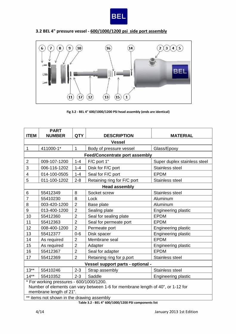
3.2 BEL 4" pressure vessel - 600/1000/1200 psi side port assembly
Fig 3.2 - BEL 4" 600/1000/1200 PSI head assembly (ends are identical)
MATERIAL DESCRIPTION QTY PART
NUMBER ITEM
Vessel
Glass/Epoxy Body of pressure vessel 1 411000-1* 1
Feed/Concentrate port assembly
Super duplex stainless steel F/C port 1" 1-4 009-107-1200 2
Stainless steel Disk for F/C port 1-4 006-116-1202 3
EPDM Seal for F/C port 1-4 014-100-0505 4
Stainless steel Retaining ring for F/C port 2-8 011-100-1202 5
Head assembly
Stainless steel Socket screw 8 55412349 6
Aluminum Lock 8 55410230 7
Aluminum Base plate 2 003-420-1200 8
Engineering plastic Sealing plate 2 013-400-1200 9
EPDM Seal for sealing plate 2 55412360 10
EPDM Seal for permeate port 2 55412363 11
Engineering plastic Permeate port 2 008-400-1200 12
Engineering plastic Disk spacer 0-6 55412377 13
EPDM Membrane seal 2 As required 14
Engineering plastic Adapter 2 As required 15
EPDM Seal for adapter 2 55412367 16
Stainless steel Retaining ring for p.port 2 55412369 17
Vessel support parts - optional -
Stainless steel Strap assembly 2-3 55410246 13**
Engineering plastic Saddle 2-3 55410352 14**
* For working pressures - 600/1000/1200. Number of elements can vary between 1-6 for membrane length of 40", or 1-12 for membrane length of 21".
** items not shown in the drawing assembly Table 3.2 - BEL 4" 600/1000/1200 PSI components list
/14 January 2013 1st Edition5
Chapter 4 - Maintenance
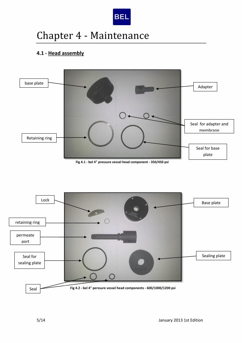
4.1 - Head assembly
base plate
Retaining ring
Seal for base
plate
Adapter
Seal for adapter and
membrane
Base plate
Sealing plate
Seal
s
Seal for
sealing plate
permeate
port
retaining ring
Lock
Fig 4.1 - bel 4" pressure vessel head component - 350/450 psi
Fig 4.2 - bel 4" perssure vessel head components - 600/1000/1200 psi
/14 January 2013 1st Edition6
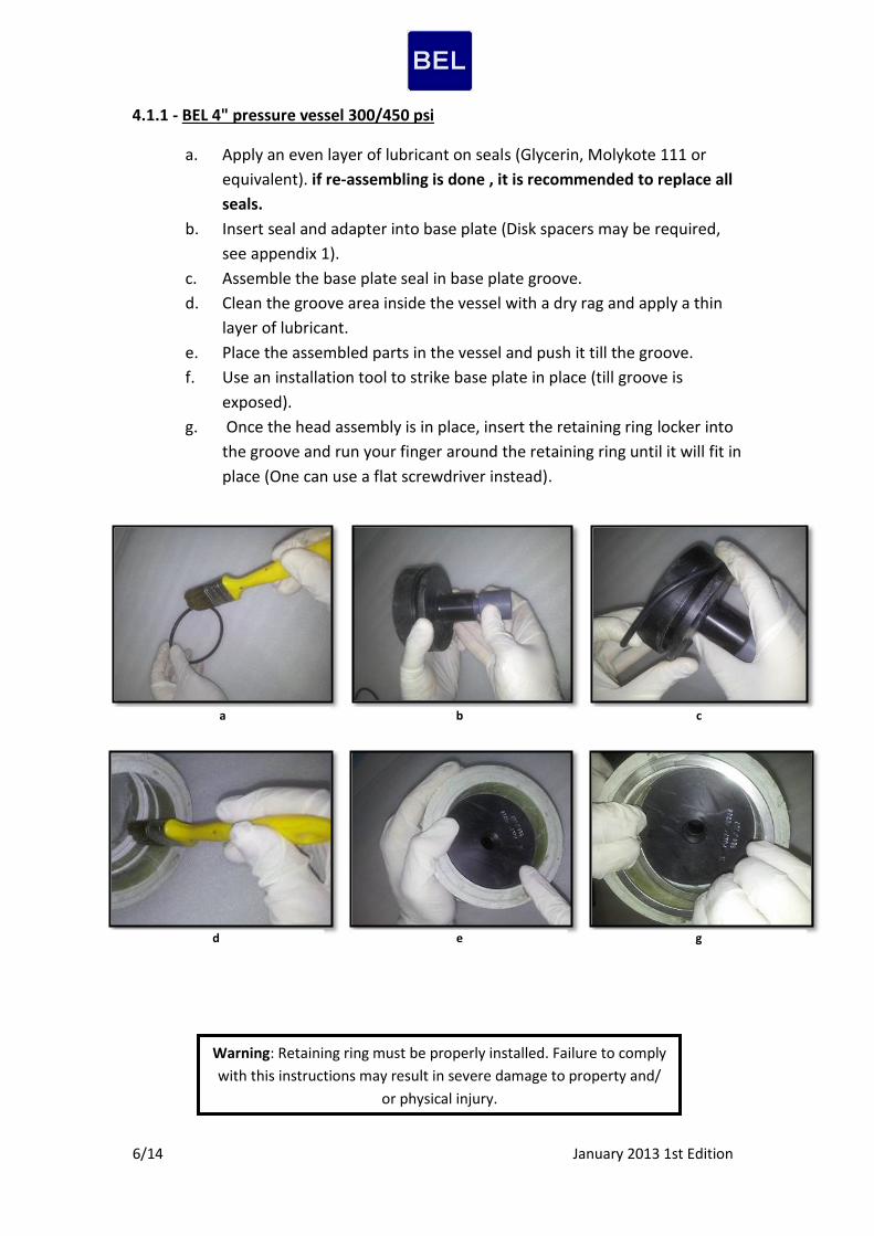
4.1.1 - BEL 4" pressure vessel 300/450 psi
a. Apply an even layer of lubricant on seals (Glycerin, Molykote 111 or
equivalent). if re-assembling is done , it is recommended to replace all
seals.
b. Insert seal and adapter into base plate (Disk spacers may be required,
see appendix 1).
c. Assemble the base plate seal in base plate groove.
d. Clean the groove area inside the vessel with a dry rag and apply a thin
layer of lubricant.
e. Place the assembled parts in the vessel and push it till the groove.
f. Use an installation tool to strike base plate in place (till groove is
exposed).
g. Once the head assembly is in place, insert the retaining ring locker into
the groove and run your finger around the retaining ring until it will fit in
place (One can use a flat screwdriver instead).
Warning: Retaining ring must be properly installed. Failure to comply
with this instructions may result in severe damage to property and/
or physical injury.
a b c
d e g

/14 January 2013 1st Edition7
4.1.2 - BEL 4" pressure vessel 600/1000/1200
a. Apply an even layer of lubricant on the seals (Glycerin, Molykote 111 or
equivalent). if re-assembling is done, it is recommended to replace all seals. b. Insert seal and permeate port into sealing plate.
c. Place permeate port with sealing plate into base plate.
d. Lock permeate port with designated retaining ring. e. Clean the groove area inside the vessel with a dry rag and apply a thin layer
of lubricant. f. Place the assembled parts inside the vessel and push it through the groove. g. Use an installation tool to strike base plate in place (until groove is exposed). h. with head assembly in place, install four locking segments into the locking
groove and secure each one of them with an Allen screw. i. visually inspect the locking segments installation to ensure that their position
is correct between head disc and the vessel groove. Make sure that each lock
is safely secured with its screw.
a
Warning: Locking segments must be properly installed. Failure to
comply with this instructions may result in severe damage to
property and/ or physical injury.
Caution! over- tightening may cause disassembly problems. it is
recommended to apply an anti- seize compound onto screw threads
to facilitate late assembly.
b-1 b-2
c d e
h

/14 January 2013 1st Edition8
4.2 - Head disassembly
a. Pressure relieve - Stop all pumps and relieve pressure.
b. Disconnect all pipes from ports connecting vessel's heads with manifolds.
c. 300/450 psi vessels - Use a flat-end screwdriver. Insert the blade
underneath the tab of the spiral retaining ring locker and pull out the end
of the spiral. Pull the spiral’s end towards the center of the head and
outwards until the whole length of the spiral retaining ring has been
extracted
600/1000/1200 vessels - Disassemble locking segments by using a
screwdriver.
d. Use a removal tool in order to remove head assembly from vessel. see
appendix 2 for BEL's extractor.
e. When disassembling is done, please refer to section 4.3 visual inspection
for further maintenance actions.
4.3 Visual inspection
Once the head have been disassembled perform a visual inspection of the
vessel head and fitting in order to locate any signs of corrosion or salt concentrations.
If corrosion or salt concentrations are found follow these steps:
4.3.1 Component inspection 4.3.2 Vessel inspection
i. Use a small wire brush to loosen any
large deposits.
ii. Place components in a shallow
container of soapy water and scrub
their surfaces with medium-grade
Scotch-Brite until all corrosion is
removed.
iii. Rinse components with clear water.
iv. Blow components dry with
compressed air.
v. Examine components for damage that
may affect structural strength or
sealing properties.
i. If any case of deposit of foreign
material has been discovered scrub
the surface with a fine Scotch-Brite
and a mild detergent solution, clean
both ends of the vessel, up to 20 cm
into the vessel.
ii. If during inspection scratches are
found on the inner surface of the
vessel up to 15 cm depth, grind the
area carefully with sand paper until
it is smooth.
Note! DO NOT strike or apply excessive force on
the ports to remove the vessel's head.
Note! if the vessel was in service for a long time, it
may be more difficult to remove the head
assembly.
/14 January 2013 1st Edition9
4.4 Loading the membrane
element
i. Flush the vessel with fresh water to
remove dust and debris.
ii. Insert Head assembly, without the
O-ring into the downstream end of
the vessel.
iii. Install the segments of the support
ring into the locking groove.
iv. Inspect the membrane element
surface to find any imperfections
that could scratch the vessel bore
element loading. If a defect is
found, which cannot be easily
corrected contact the element
manufacturer.
v. Apply a thin layer of lubricant to
lubricate the inside of the vessel
near the groove.
This will assist membrane
element loading and reduce the
risk of inadvertently scratching
the vessel bore.
vi. Install the brine seal on the
upstream end of the membrane
element so that the seal's open side
faces upstream (if it is not already
installed by the manufacturer).
vii. Load the first element into the
upstream of the vessel .Leave 10
cm of the element projecting out of
the vessel to facilitate connection
with the next element.
viii. Apply a small amount of Lubricant
onto the O-ring of the
interconnector.
ix. Connect the interconnector to the
projected end of the loaded
element.
x. Line up the next element and
assemble it to the inter connector
which is already on the first
element. Carefully maintain
element alignment during
assembly, misalignment may
result damage to the membrane
and vessel parts.
xi. Line up the next element and
assemble it to the interconnector
which is already on the first
element.
xii. Carefully push the two elements
into the vessel until the second
element is projecting from the
vessel approximately 10 cm.
Repeat the above steps until all
membrane elements have been
assembled.
xiii. Calculate the correct shimming
distance (see Annex 2) in order to
avoid impact damage on the
membrane and head parts during
pressure drop.
xiv. Insert the shimming spacers on the
upstream head assembly
(Membrane adapter) so that the
sum of their lengths will be equal
to the shimming distance.
xv. Install the upstream head assembly
as described in section 4.1.
xvi. Remove the downstream head
assembly and reassemble it with
the O-ring.

/14 January 2013 1st Edition11
Appendixes
Appendix 1 - Shimming procedure
Shimming is needed in order to keep minimum membrane movement. Apply
shimming at the feed side only.
First, make sure the membranes is fully pressed towards the brine side. Load the head
assembly and the membranes. In order to check that the membrane is fully pressed
against the brine side, pull out the head assembly and measure the distance between
the membrane and the locker (See "Y" in the drawing below). This distance is equal
to the total length of the head assembly (110 mm for 300/450 psi vessels, 135 mm for
600/1000/1200 psi vessels). It is important to mention that measuring of "Y" is an
option and it's not mandatory. However it is very important* to make sure that the
membrane is fully pressed before applying the shimming procedure.
Correct shimming can be achieved by using the following formulas:
For BEL 4" 300/450 psi:
Let X (see drawing above) be the distance between the groove and the membrane on
the feed side. Measure this distance by using a caliber between the inner side of the
locker and membrane.
- Thickness of base plate
- Thickness of adapter
* Note: this process is highly recommended for vessels containing 3 membranes and above.
Y
Head assembly Membrane
Feed Concen.
X

/14 January 2013 1st Edition11
For BEL 4" 600/1000/1200 psi-
Let X (see drawing above) be the distance between the inner side of the locker and the
membrane on feed side.
- Thickness of sealing plate
- Thickness of base plate
- Thickness of permeate port base
- Thickness of adapter
After installing the shimming, a space of 1 mm to install the retaining ring locker /
locker shall remain. In case of extra space or too little space, remove or add spacers
respectively until receiving a satisfying result.
/14 January 2013 1st Edition12
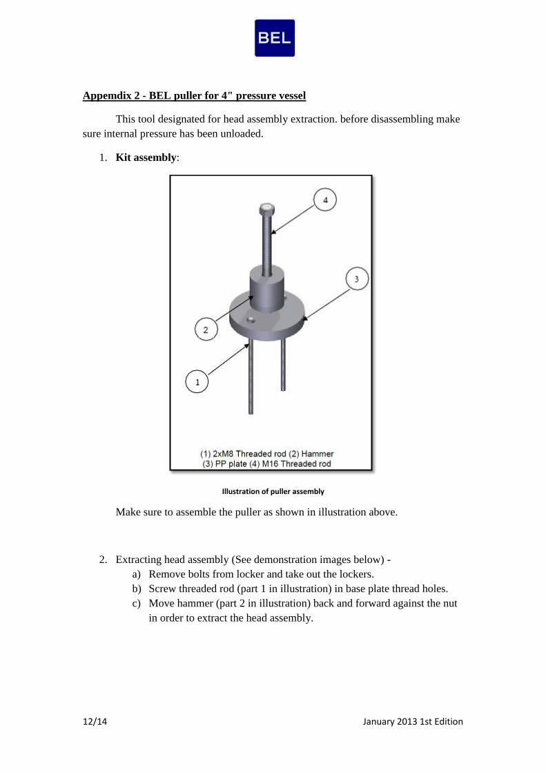
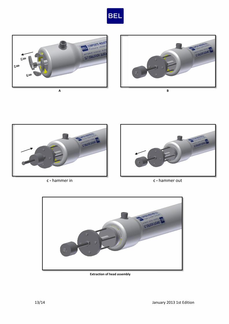
Appemdix 2 - BEL puller for 4" pressure vessel
This tool designated for head assembly extraction. before disassembling make
sure internal pressure has been unloaded.
1. Kit assembly:
Illustration of puller assembly
Make sure to assemble the puller as shown in illustration above.
2. Extracting head assembly (See demonstration images below) -
a) Remove bolts from locker and take out the lockers.
b) Screw threaded rod (part 1 in illustration) in base plate thread holes.
c) Move hammer (part 2 in illustration) back and forward against the nut
in order to extract the head assembly.
/14 January 2013 1st Edition13
A B
C - hammer in C - hammer out
Extraction of head assembly
/14 January 2013 1st Edition14
Appemdix 3 - O-Ring replacement and scratches treatment procedure
1. Preparations
Please prepare the following items before procedure:
i. New intact O-Ring seal.
ii. Clean cloth.
iii. Lubricant.
iv. BEL Pusher-Puller (optional).
2. O-Ring Replacement procedure
i. Remove head assembly.
ii. Clean vessel internal surface at sealing area (O-Ring area) with clean damp
cloth.
iii. Ensure vessel sealing area is smooth and free of scratches. See next procedure
for scratch treating.
iv. Assemble the head assembly and apply full and reach layer of lubricant on
seals, vessel's groove and vessel's sealing area.( Ensure the base plate/sealing
plate O-Ring groove is clean and free of scratches).
v. Install the head assembly.
3. Scratches treatment procedure
i. Clean vessel internal surface at sealing area (O-Ring area) with clean damp
cloth.
ii. Locate the scratch at the O-Ring sealing area. Scratches out of this area will
not cause leaks, therefore will not be treated.
iii. Grind out the scratch using Extra-Fine sand paper (P400) until scratch is flat
and smooth. DO NOT grind deep into the vessel, this might cause permanent
damage to the vessel.
Note: In case of deep scratches or layers de-lamination please consult BEL
engineering department.


