technical description - pressure transmitter selection ... · pdf filepressure transmitter...
TRANSCRIPT
Pressure transmitter selection How to select the right pressure transmitter for your application
Technical description TD/PRESSURE/001-EN
OverviewThe variety of potential applications and installation locations for pressure measurement means it is difficult to set any hard and fast rules. This guide advises on some basic guidelines that will help to shape and narrow down the eventual choice of pressure measurement device for your application.
Transducers or transmitters?
The first stage is whether to opt for a transducer or a transmitter. Although the terms are often confused, there are several differences between transducer and transmitter devices.
A transducer creates a low-level electronic signal in response to changes in applied or differential pressure. As with transmitters, transducers feature an internal sensor that converts the applied force into an electrical signal, from which the measurement is derived.
Transducers are generally unsuitable for the harsh environments typical of many industrial applications. The transducer body is
usually small and cannot easily be fitted to standard industrial piping. In contrast to transmitters, which are designed for use in industrial applications, most pressure transducers are either for niche applications or for use in laboratories.
Transducers have a number of drawbacks that make them generally unsuitable for widespread use in industrial environments. They are generally most suited to very contained environments where there is no risk of water or dust ingress, for example. They are also commonly poorly protected against the effects of overpressure or damage caused by sudden variations in process conditions.
As well as being much less rugged, transducers lack sufficient energy to transmit a signal over the same distance that transmitters can. There is also a much wider range of temperature transmitters certified and available for use in hazardous areas and areas with extremes of temperature and humidity.
Compared to transmitters, most transducers also have offer a very limited amount of adjustability and have inferior stability and measurement accuracy. They offer limited compensation for variations in process or ambient conditions such as
Advice and guidance for selecting pressure transmitters and ancillary equipment.
Measurement made easy
2 TD/PRESSURE/001-EN | Pressure transmitter selection. How to select the right pressure transmitter for your application
Pressure transmitter selection
temperature and are often fixed range devices, which can only measure within a set span.
Transmitters for measuring pressure or differential pressure, on the other hand, comprise two basic parts. A primary element directly or indirectly in contact with the process collects the measurement, while a secondary electronics package translates the output from the primary element into a communications signal enabling it to relay information either via a fieldbus protocol such as Foundation Fieldbus or Profibus, or a standard 4 to 20 mA dc output signal.
These secondary electronics are highly sophisticated and perform many functions that transducers cannot. Variations in process or ambient conditions measured by the primary sensor, for example, can be automatically compensated for before being converted into a 4 to 20 mA signal. Other functions include square root extraction for flow applications, totalizers, and reverse flow output function.
This minimises unwanted measurement errors and gives the transmitter a very stable output. Operators can also calibrate the transmitter over a range of input pressures, enabling one unit to be used to measure a range of spans.
Consider your operating environment
Modern pressure transmitters should be able to comfortably handle adverse temperatures, humidity and vibration conditions provided they are within design specification limits. Minimising the effects of such conditions will help to maximise the transmitter’s operational life.
TemperatureMost electronic transmitters are suitable for ambient conditions ranging from lows of –20°C to –40°C to highs of 60°C to 85°C, although this may not always be the case for certain types, for example where special filling materials have been specified for the transmitter.
An application’s ambient temperature conditions can significantly affect transmitter accuracy. This can include not just the inherent background temperature of the installation location, but also heat generated from a process or radiated from surrounding process equipment and piping.
High temperatures can have a detrimental effect, potentially causing premature component failure. Exceeding the device’s parameters can have a significant effect on performance. Low temperatures, for example, can cause fill fluids to become more viscous, whilst high temperatures can cause them to vaporise. Variations in ambient temperature and pressure can also have an impact, particularly if the transmitter’s calibrated span is a small proportion of its upper range limit.
To overcome these problems, the temperature of the transmitter should ideally be kept as close to room temperature as possible for maximum life expectancy.
Careful consideration also needs to be exercised when installing a transmitter outdoors. Atmospheric conditions such as direct sunlight or high winds can cause heating or cooling of transmitters, which can adversely affect their operation.
Humidity Vapour caused by humid conditions can sometimes penetrate the transmitter housing and attack sensitive components. Prolonged exposure to high humidity can also result in corrosion of the transmitter housing and mountings.
Transmitter housings are designed to protect electrical components against the ingress of moisture caused by humidity. However, even housings with an IP rating for moisture or hosedown applications can encounter problems if the housing cover is removed during commissioning, operation or maintenance.
Some manufacturers employ various methods such as using potting material to protect transmitter electronics against humidity. Whilst they can delay humidity problems, these methods do not provide a long-term solution. The only true prevention against humidity is for the transmitter housing to be hermetically sealed.
VibrationAvoid installing a transmitter in an area subject to prolonged or unnecessary levels of vibration, as this can reduce the service life of the transmitter. To protect against potential damage or malfunction caused by vibration, transmitters should be mounted in a location that will be unaffected by vibration when a process is in operation.
Pressure transmitter selection. How to select the right pressure transmitter for your application | TD/PRESSURE/001-EN 3
Two wire, digital or wireless?
There are many different types of transmitters, each of which use different techniques to transmit a signal.
The role of the transmitter is to amplify and condition the signal so that it can be relayed over long distances to the control room or to localised devices such as indicators, recorders and controllers without deterioration or interference.
For the majority of applications where power is readily available, the two-wire transmitter, which uses a 4 to 20 mA current both to operate its circuitry and to relay a signal, is often the most practical choice. Because the current is protected against the effects of changing resistance along the line, signals can be relayed over long distances.
Where transmission of accurate data or large volumes of data (such as diagnostic information) is essential, the best choice may be to opt for digital transmitters. Digital signal transmission allows much more data to be relayed between the instrument and the control room. Fieldbus technology such as Foundation Fieldbus and Profibus PA (for process automation) and DP (for discrete or factory automation), enable data to be quickly relayed to the control room, where it can be used by the control system to make informed and immediate operational and management decisions.
Where high speed transmission of data is less essential, a WirelessHART enabled device may provide the solution.
WirelessHART provides the ideal solution for any application where it is either uneconomical or impractical to have a wired device. The ability to remotely interrogate a wireless device from up to 200 metres away also eliminates the need for operators and maintenance staff to have to visit potentially unsafe areas, such as high up on a column, for example.
With wiring and installation costs accounting for almost 50 percent of the total cost of a device, it makes both financial and technological sense to use wireless devices wherever possible. Wireless devices used to be largely confined to specialist applications in remote installations, such as water distribution or oil and gas. However, the arrival of the WirelessHART protocol means industry now has an international standard that enables wireless instruments to communicate a wealth of standardised information throughout plant networks.
Reliability is crucial, and the meshed architecture of WirelessHART networks provides a robust solution that can reroute information to bypass malfunctioning nodes and provide a secure service.
ABB’s pressure transmitters are available with a choice of communications standards including HART/4 to 20 mA, Profibus, Modbus and Foundation Fieldbus, enabling data to be transmitted from the device to a centralised control system.
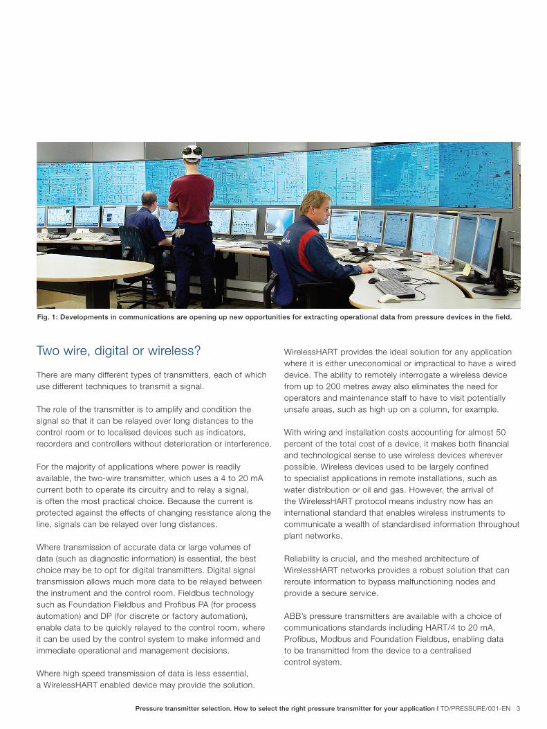
Fig. 1: Developments in communications are opening up new opportunities for extracting operational data from pressure devices in the field.
4 TD/PRESSURE/001-EN | Pressure transmitter selection. How to select the right pressure transmitter for your application
Pressure transmitter selection
Is the application hazardous?
Any electronic instrument either stores electrical energy or is a source of electrical energy. In certain conditions, this energy, if discharged, could ignite any accumulated mixtures of flammable gases, combustible dusts and ignitable fibres that may be present.
Caution needs to be exercised when locating any electronic pressure transmitter in a hazardous or potentially hazardous location. There needs to be careful analysis of the conditions that might arise under normal operating conditions and/or fault conditions. Attention also needs to be given to preventing ignition of any hazardous atmospheres that might be present.
Various international standards, such as ATEX, FM, IEC, INMETRO, GOST, NEPSI and SAA set out various measures for assessing the risk posed by hazardous environments and the steps that need to be taken to minimise the risk of ignition.
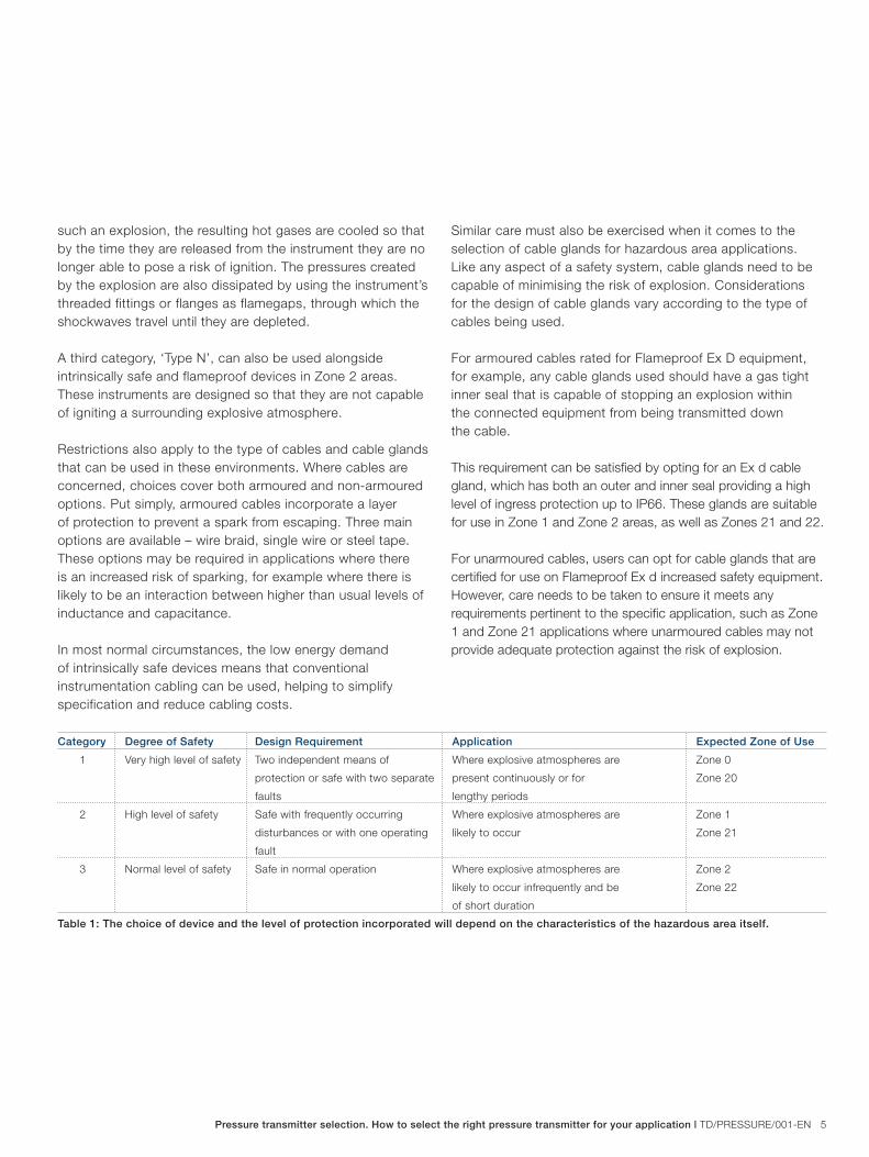
The choice of device and the level of protection incorporated will depend on the characteristics of the hazardous area itself. Under the ATEX Directive, for example, equipment is designated by the type of potentially explosive atmosphere in which the equipment may be used – Group 1 for underground mines and Group 2 for surface industries.
In Group 2, ATEX also defines categories of equipment, specified by their protection characteristics. It also designates the hazardous location zones they can be used in - zones 0, 1 and 2 for gases, vapours and mists and zones 20, 21 and 22 for dusts.
A table showing the zones and the category of equipment that can be used in them is shown in figure 1.
The aim of the standard is to eliminate the risk of an explosion caused by a spark or a hot surface. The differing requirements of each zone mean that operators need to select the device that offers the best levels of protection.
The high safety requirements of Zone 0, for example, mean that only intrinsically safe devices can be used. These devices use low-energy signalling to limit the energy transferred to a hazardous area to a level well below that needed to pose a risk of explosion. Though very low, these energy levels are more than sufficient to enable efficient operation with most instrumentation systems.
These same devices can also be used to satisfy the requirements of Zone 1 and 2 areas. In Europe under ATEX, operators can also use flameproof devices in Zone 1 areas. These devices are built to safeguard the surrounding environment against an internal explosion. In the event of
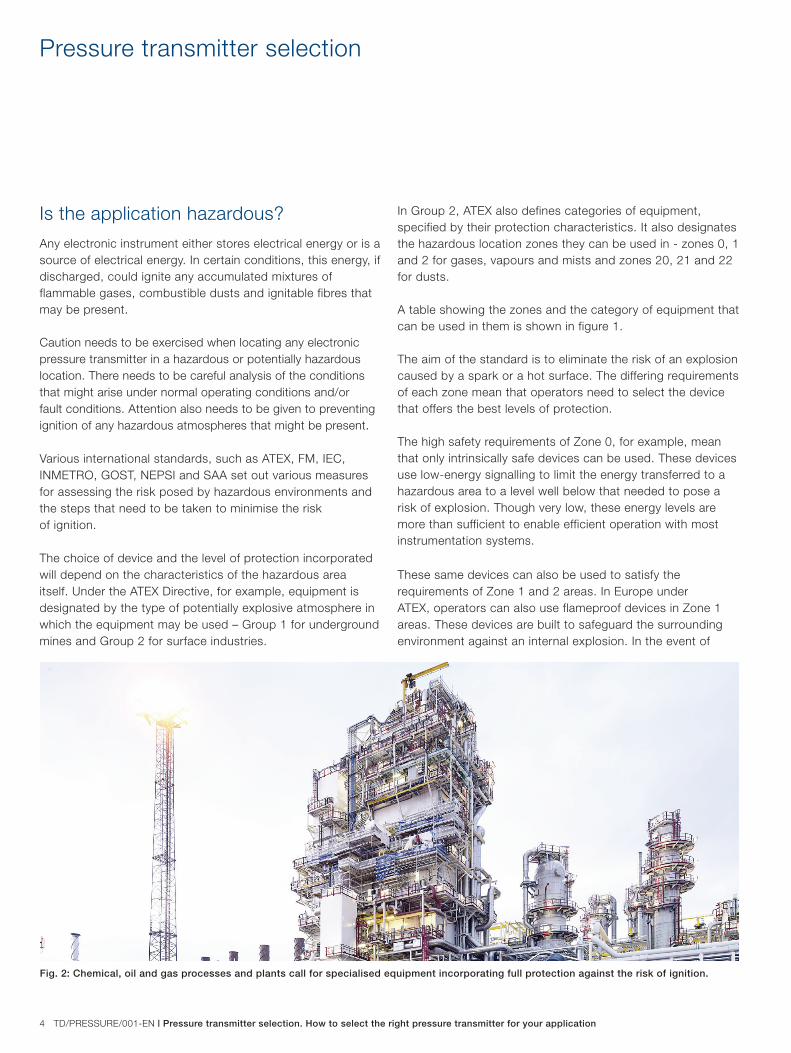
Fig. 2: Chemical, oil and gas processes and plants call for specialised equipment incorporating full protection against the risk of ignition.
Pressure transmitter selection. How to select the right pressure transmitter for your application | TD/PRESSURE/001-EN 5
such an explosion, the resulting hot gases are cooled so that by the time they are released from the instrument they are no longer able to pose a risk of ignition. The pressures created by the explosion are also dissipated by using the instrument’s threaded fittings or flanges as flamegaps, through which the shockwaves travel until they are depleted.
A third category, ‘Type N’, can also be used alongside intrinsically safe and flameproof devices in Zone 2 areas. These instruments are designed so that they are not capable of igniting a surrounding explosive atmosphere.
Restrictions also apply to the type of cables and cable glands that can be used in these environments. Where cables are concerned, choices cover both armoured and non-armoured options. Put simply, armoured cables incorporate a layer of protection to prevent a spark from escaping. Three main options are available – wire braid, single wire or steel tape. These options may be required in applications where there is an increased risk of sparking, for example where there is likely to be an interaction between higher than usual levels of inductance and capacitance.
In most normal circumstances, the low energy demand of intrinsically safe devices means that conventional instrumentation cabling can be used, helping to simplify specification and reduce cabling costs.
Similar care must also be exercised when it comes to the selection of cable glands for hazardous area applications. Like any aspect of a safety system, cable glands need to be capable of minimising the risk of explosion. Considerations for the design of cable glands vary according to the type of cables being used.
For armoured cables rated for Flameproof Ex D equipment, for example, any cable glands used should have a gas tight inner seal that is capable of stopping an explosion within the connected equipment from being transmitted down the cable.
This requirement can be satisfied by opting for an Ex d cable gland, which has both an outer and inner seal providing a high level of ingress protection up to IP66. These glands are suitable for use in Zone 1 and Zone 2 areas, as well as Zones 21 and 22.
For unarmoured cables, users can opt for cable glands that are certified for use on Flameproof Ex d increased safety equipment. However, care needs to be taken to ensure it meets any requirements pertinent to the specific application, such as Zone 1 and Zone 21 applications where unarmoured cables may not provide adequate protection against the risk of explosion.
Category Degree of Safety Design Requirement Application Expected Zone of Use
1 Very high level of safety Two independent means of Where explosive atmospheres are Zone 0
protection or safe with two separate present continuously or for Zone 20
faults lengthy periods
2 High level of safety Safe with frequently occurring Where explosive atmospheres are Zone 1
disturbances or with one operating likely to occur Zone 21
fault
3 Normal level of safety Safe in normal operation Where explosive atmospheres are Zone 2
likely to occur infrequently and be Zone 22
of short duration
Table 1: The choice of device and the level of protection incorporated will depend on the characteristics of the hazardous area itself.
6 TD/PRESSURE/001-EN | Pressure transmitter selection. How to select the right pressure transmitter for your application
Pressure transmitter selection
Satisfying Functional Safety Considerations for pressure transmitter selection also extend to Functional Safety, or the ability of a safety instrumented system to carry out the actions needed to achieve or maintain a safe state. In assessing this ability, an instrument with a safety function is rated according to the probability of this function being able to perform the required actions under specific stated conditions within a stated period of time.
These safety functions are assigned one of four Safety Integrity Levels. Safety Integrity Level 4 hasthe highest level of safety integrity, while Safety Integrity Level 1 has the lowest. These levels are defined in terms of the required probability of failure on demand average (PFDavg), which is the average probability that the system will be in a failed state when a demand occurs.
ABB’s Safety Pressure Transmitters provide a single range of pressure measurement devices for hazardous applications that call for SIL2 and SIL3 integrity, such as in the chemical, petrochemical, pharmaceutical and oil and gas industries. In a SIL2 environment, a single safety transmitter can provide the same level of protection as two conventional devices, eliminating the need for two devices and effectively reducing operating and lifecycle costs by 50%.
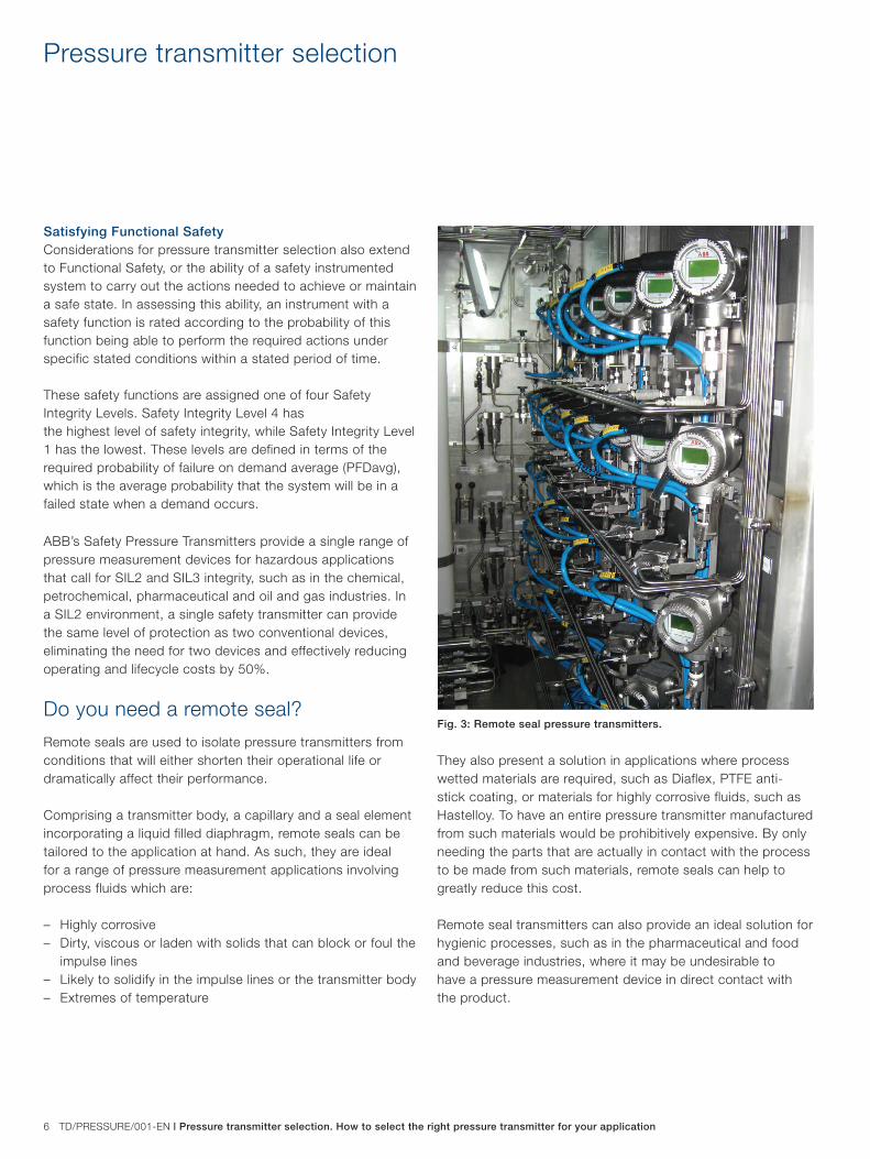
Do you need a remote seal?
Remote seals are used to isolate pressure transmitters from conditions that will either shorten their operational life or dramatically affect their performance.
Comprising a transmitter body, a capillary and a seal element incorporating a liquid filled diaphragm, remote seals can be tailored to the application at hand. As such, they are ideal for a range of pressure measurement applications involving process fluids which are: – Highly corrosive– Dirty, viscous or laden with solids that can block or foul the
impulse lines– Likely to solidify in the impulse lines or the transmitter body– Extremes of temperature
They also present a solution in applications where process wetted materials are required, such as Diaflex, PTFE anti-stick coating, or materials for highly corrosive fluids, such as Hastelloy. To have an entire pressure transmitter manufactured from such materials would be prohibitively expensive. By only needing the parts that are actually in contact with the process to be made from such materials, remote seals can help to greatly reduce this cost.
Remote seal transmitters can also provide an ideal solution for hygienic processes, such as in the pharmaceutical and food and beverage industries, where it may be undesirable to have a pressure measurement device in direct contact with the product.
Fig. 3: Remote seal pressure transmitters.
Pressure transmitter selection. How to select the right pressure transmitter for your application | TD/PRESSURE/001-EN 7
What else do you want to measure?
For certain applications involving the measurement of gases or fluids subject to rapid density changes, it may be advantageous to use a multivariable pressure transmitter device. These devices offer a three-in-one solution for the measurement of flows of liquids, steam or gas with absolute pressure and temperature compensation, ideal for calculating changes in flow density.
Previously, the main method of calculating flow density involved deriving measurements against known standard conditions. Though fine for applications with constant or relatively minor deviations in process conditions, this approach is less effective for installations where high accuracy measurement is required or where fluctuations in the flow medium are likely to occur.
For ABB’s multivariable transmitter, the combination of three different measurements into one device enables users to select appropriate accuracies for their applications ranging from 0.04% to 0.075%.
Incorporating three different forms of measurement into one unit can also significantly reduce installation costs savings on installation through the need for fewer devices and a reduction in the amount of cabling and I/O devices required.
Summary
ABB has wide experience in the manufacture and supply of pressure measurement solutions derived from a host of industrial applications worldwide. For more information and advice on selecting and installing pressure measurement devices, contact 0870 600 6122, email [email protected] or visit www.abb.com/measurement.
TD/P
RE
SS
UR
E/0
01–E
N
01.2
015
Contact us
NoteWe reserve the right to make technical changes or modify the contents of this document without prior notice. With regard to purchase orders, the agreedparticulars shall prevail. ABB does not accept any responsibility whatsoever for potential errors or possible lack of information in this document.
We reserve all rights in this document and in the subject matter and illustrations contained therein. Any reproduction, disclosure to third parties or utilization of its contents - in whole or in parts – is forbidden without prior written consent of ABB.
Copyright© 2015 ABBAll rights reserved
ABB LimitedProcess AutomationHoward RoadEaton SoconSt NeotsCambridgeshirePE19 8EUTel: +44 (0)870 600 6122Email: [email protected]
ABB Inc.Process Automation125 E. County Line RoadWarminster PA 18974USATel: +1 215 674 6000Fax: +1 215 674 7183
www.abb.com