
IAP 2008 12.091 ipeclal Toplcs Course January 8 - 22, XiK1
Department d Eadh Atmosphdc &Planetary Sclences Mauachuseits lnrfihrh of Technology
Cambridge, MA 021 39
SESSION 3: January 15,2008

1. Introduction to terrestrial impact cratering
2. Review of some major research studies of terrestrial impact craters
3. Tools of analysis4. Chesapeake Bay Impact Crater:
Environmental and Geochemical Research Studies
5. Summary 2
January 15, 2008: IAP
2008: 12.091: Session 3: P
. ILA

The course work involves the following:January 8, 10, 15, 17, 22 10 AM to Noon5 sessions each of 2 hours - 25%Study/work assignments – 4 - 20%ProjectLiterature Survey &Writing a report - 30%
Project Presentation - 25%Required percentage to pass this course is 95%Grading: P/F
3
January 15, 2008: IAP
2008: 12.091: S
ession 3: P. ILA

4
January 15, 2008: IAP
2008: 12.091: S
ession 3: P. ILA

1. Fundamental events of impact cratering2. Basic principles of aeromagnetic survey
measurement3. Basic principles of gravity anamoly measurement4. Phenomenology of impact cratering5. Determination of impact cratering parameters6. Concepts of hydrocode modeling7. Age determination by conventional K – Ar method8. Neutron Activation Analysis 9. Inductively Coupled Plasma Mass Spectrometry10.Electron microprobe analysis
5
January 15, 2008: IAP
2008: 12.091: Session
3: P. ILA

Scientists, typically, divide the formation of an impact crater into three main stages:
1. contact and compression,2. excavation, 3. modification.
Ref: Melosh (1989) & French (1998)6
January 15, 2008: IAP
2008: 12.091: S
ession 3: P. ILA
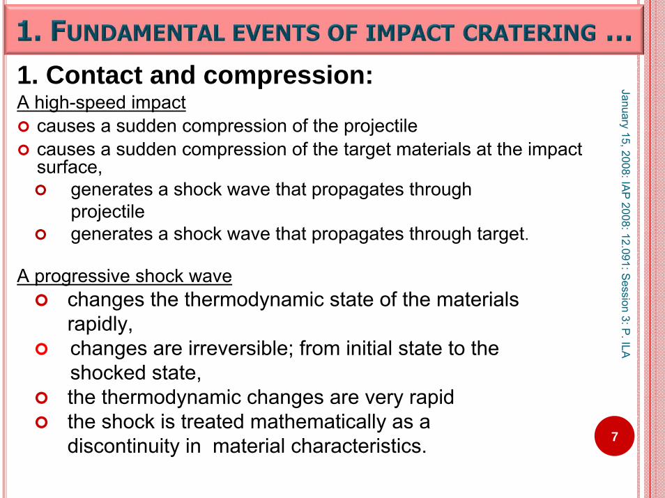
1. Contact and compression:A high-speed impact
causes a sudden compression of the projectile causes a sudden compression of the target materials at the impact surface,
generates a shock wave that propagates throughprojectile generates a shock wave that propagates through target.
A progressive shock wave changes the thermodynamic state of the materials rapidly, changes are irreversible; from initial state to the shocked state, the thermodynamic changes are very rapidthe shock is treated mathematically as a discontinuity in material characteristics. 7
January 15, 2008: IAP
2008: 12.091: Session 3: P
. ILA

A rarefaction wave reflects back when the shock wave reaches the rear end of the projectilethe target surface releases the previously compressed material to low pressures.
Speed of the rarefaction wave is greater than that of the hemispherically-expanding shock wave.The shock wave finally achieves the shape of a thin shell.
8
January 15, 2008: IAP
2008: 12.091: S
ession 3: P. ILA

2. ExcavationParticle velocity of the target is the material velocity. This opens the crater during the excavation stage. The material velocity has a radial component,and a complementary tangential component,
tending to deflect the particle trajectories towards the surface, pushing material into the target,expelling material from the expanding crater.
9
January 15, 2008: IAP
2008: 12.091: S
ession 3: P. ILA
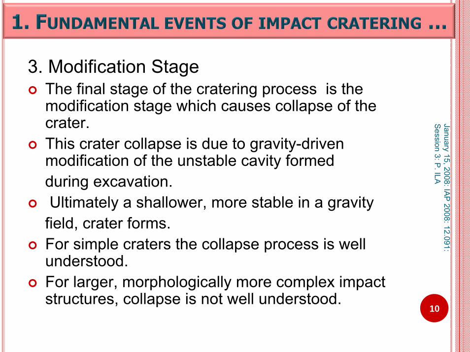
3. Modification StageThe final stage of the cratering process is the modification stage which causes collapse of the crater.This crater collapse is due to gravity-driven modification of the unstable cavity formedduring excavation.Ultimately a shallower, more stable in a gravity
field, crater forms.For simple craters the collapse process is well understood.For larger, morphologically more complex impact structures, collapse is not well understood.
10
January 15, 2008: IAP
2008: 12.091: S
ession 3: P. ILA

Aeromagnetic surveyMeasures intensity of the Earth’s magnetic field
using magnetometers mounted in an airplane or helicopter.
The differences between actual measurements and theoretical values represent anomalies in the magnetic field.
The anamolies in turn represent changes in rock type or thickness of rocks.
The contour maps generated from the survey provide information to consider whether there is crater or other geologic formation in that region.
11
January 15, 2008: IAP
2008: 12.091: S
ession 3: P. ILA

Aeromagnetic surveys are conducted on a wide variety of terrains; with varying sampling rates, and line spacings.
Contour maps represent the results.
The survey grid defines the continuous magnetic field sufficiently well to justify interpolation.
Ref: A. B. Reid , Aeromagnetic Survey Design, Geophysics Vol.45 No.5 (May 1980) p 973-976.
12
January 15, 2008: IAP
2008: 12.091: S
ession 3: P. ILA

Aeromagnetic measurement parameters:
The spatial wave length λ N and spacing Δ x of line of samples are related by the Nyquist equation
λ N = 2 Δ x (1)
Hence, it is very important to determine a priori the most appropriate value for Δ x in terms of height of the sensor above source bodies.
13
January 15, 2008: IAP
2008: 12.091: S
ession 3: P. ILA

Aeromagnetic measurement parameters …
<C2(r)> approaches unity for sources of considerable depth extent. <S2(r)> approaches unity for sources of small upper surface area.So the equation (1) reduces to<E(r)> = 4Π2km
2 exp(-2hmr)
Ref: A. B. Reid , Aeromagnetic Survey Design, Geophysics Vol.45, No.5 (May 1980) p 973-976.
14
January 15, 2008: IAP
2008: 12.091: S
ession 3: P. ILA

Aeromagnetic measurement parameters …
For a given survey spacing Δ x, there will be aNyquist wavenumber rN and is given byrN = 2Π / λ N = Π/ Δ x
The fraction of the power FT = exp(- 2Πhm / Δ x)hm = mean elevation difference between the top surfaces of the magnetic areas and the sensor
Here Δ x should be taken to be the line spacing or in-line sample spacing, which ever is larger.
15
January 15, 2008: IAP
2008: 12.091: S
ession 3: P. ILA
The following figures are courtesy of USGS:Ref: V. J. S. GrauchHigh-Resolution Aeromagnetic Survey to Image
Shallow Faults, Dixie Valley Geothermal Field, Nevada
USGS Open File Report ofr-02-0384_508.pdfFigure 3 p. 6Figure 5 p. 8Figure 6 p. 9
16
January 15, 2008: IAP
2008: 12.091: S
ession 3: P. ILA

17
Reduced-to-pole (RTP) aeromagnetic data shown in color shaded-relief, illuminated from the northwest. Figure courtesy of USGS
January 15, 2008: IAP
2008: 12.091: S
ession 3: P. ILA

18
Separation of the Reduced to Pole aeromagnetic data into different anomaly-width (depth) components using matched filtering. Figure courtesy of USGS.
January 15, 2008: IAP
2008: 12.091: S
ession 3: P. ILA

19
Interpreted faults, color-coded according to estimated depth, compared to faults mapped atthe surface from Smith et al. (2001). Figure courtesy of USGS.
January 15, 2008: IAP
2008: 12.091: S
ession 3: P. ILA

Gravity is one of the universal forces of nature. It is an attractive force between all things. The gravitational force between two objects depends on their masses, and the distance between them. Gravitational force can be observed when at least one of the objects is very large (like the Earth). Gravity surveying consists of looking at the subsurface structure based on the differences in densities of the subsurface rocks. Gravity anamoly variations can give ideas about depth, size and shape of the body of interest. Earth’s gravity of acceleration is
980 cm /s2 or 9.80 m /s2
20
January 15, 2008: IAP
2008: 12.091: S
ession 3: P. ILA
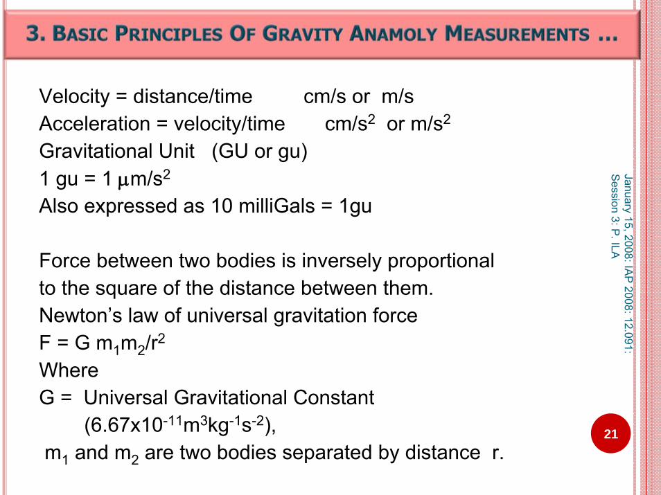
Velocity = distance/time cm/s or m/sAcceleration = velocity/time cm/s2 or m/s2
Gravitational Unit (GU or gu)1 gu = 1 μm/s2
Also expressed as 10 milliGals = 1gu
Force between two bodies is inversely proportional to the square of the distance between them.Newton’s law of universal gravitation forceF = G m1m2/r2
Where G = Universal Gravitational Constant
(6.67x10⁻¹¹m3kg-1s-2), m1 and m2 are two bodies separated by distance r.
21
January 15, 2008: IAP
2008: 12.091: S
ession 3: P. ILA

Gravitational field measured by using a typical device like LaCoste & Romberg gravimeter. The device consistofvery sensitive spring and mass of weight. The weight is attached to a beam and a spring .As gravity increases, the weight is forced downwards, stretching the spring. By adjusting a screw, the beam is brought back to horizontal position.Gravitational force is proportional to the amount of movement required.
January 15, 2008: IAP
2008: 12.091: S
ession 3: P. ILA
22
Adjustment Screw

The gravitational field is mapped using the gravitational potential, U.Potential = Force x distanceU = GM/r
Ref:P. Keary & M. Brooks, 1991. An Introduction to Geophysical Exploration. W. Lowrie, 1997. Fundamentals of Geophysics.
23
January 15, 2008: IAP
2008: 12.091: S
ession 3: P. ILA
24
January 15, 2008: IAP
2008: 12.091: S
ession 3: P. ILA
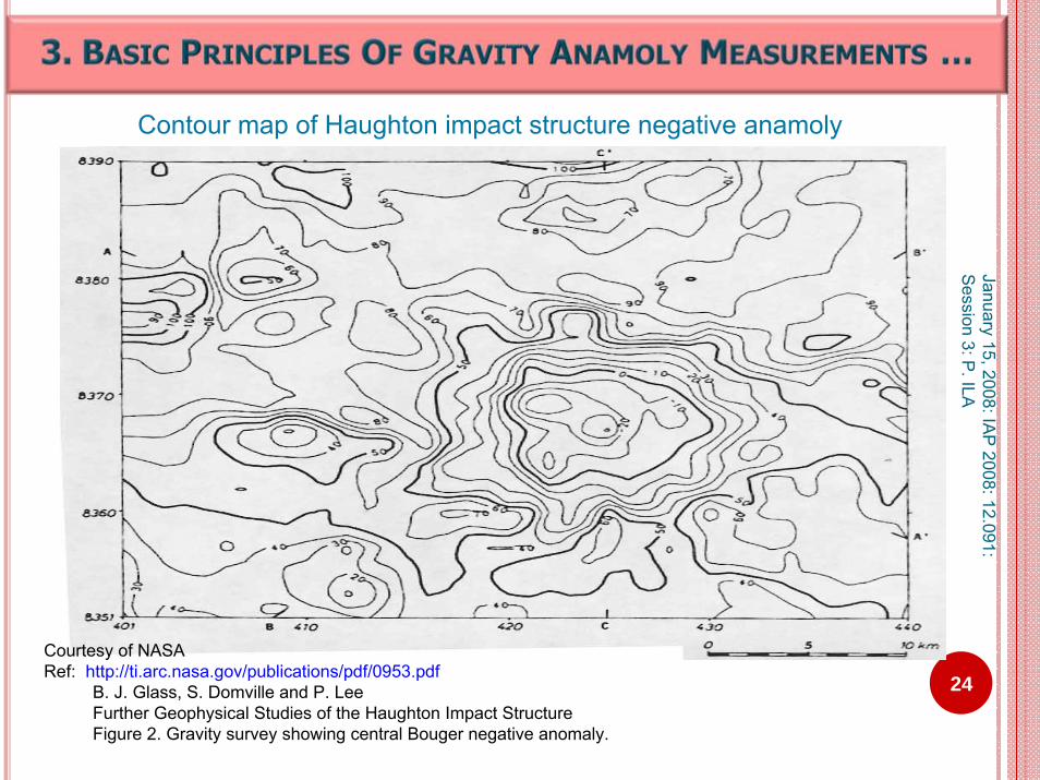
Courtesy of NASARef: http://ti.arc.nasa.gov/publications/pdf/0953.pdf
B. J. Glass, S. Domville and P. LeeFurther Geophysical Studies of the Haughton Impact StructureFigure 2. Gravity survey showing central Bouger negative anomaly.
Contour map of Haughton impact structure negative anamoly

25
January 15, 2008: IAP
2008: 12.091: S
ession 3: P. ILA
Courtesy of NASARef: http://ti.arc.nasa.gov/publications/pdf/0953.pdf
B. J. Glass, S. Domville and P. LeeFurther Geophysical Studies of the Haughton Impact StructureFigure 3. Merged gravity dataset contour plot.
Merged gravity dataset contour plot

Quantitative models
Physical quantification of the mechanics involved in meteorite impacts:
Impactor traveling with hypervelocity Final impact dynamics
diffusion, turbulence of flight, geometry, rotation of flight, aerodynamic pressure, drag and energy transfer,
26
January 15, 2008: IAP
2008: 12.091: S
ession 3: P. ILA

Quantitative models …
Final Impact parameters …ablation, radiation, target density, atomic collision, potential energy of atomic interaction, shock wave propagation, cratering, melting, oblique impacting 27
January 15, 2008: IAP
2008: 12.091: S
ession 3: P. ILA

In the words of Melosh (1980):“To gain a basic understanding of the sheer magnitude and striking spectacle that is a meteorite impact, it may be more effective (if not more understandable) to focus on simple energy relationships”
“This approach has been quite successful for small meteorite impacts, however for large scale impacts, our ability to understand the processes involved decreases as the size of the meteorite increases.”
28
January 15, 2008: IAP
2008: 12.091: S
ession 3: P. ILA

Impact energy of a meteoriteThe impact energy of a meteorite can be
estimated by calculating its kinetic energy from its size ( of certain radius) and speed ( velocity of impact).
Total Kinetic Energy = ( ½)MV2 .The units can be in g cm2/sec2 or kg m2/sec2 .M = Mass of the meteorite kg .V = velocity of the meteorite km/sec .
29
January 15, 2008: IAP
2008: 12.091: S
ession 3: P. ILA

Units of energy Joule
J = kg x m2 /s2
ErgErg = g cm2/s2
Giga Joules (GJ). 1 GJ = 109 J
1 million tons of dynamite equivalent is1 Mt = 4 x 10¹⁵ J.
30
January 15, 2008: IAP
2008: 12.091: S
ession 3: P. ILA

Consider some realistic limits for the parameters.
Velocity of a meteorite must be at least 11 km/s. Reason being,
this is the estimated minimum velocity for aprojectile shot from earth to overcome gravity andreach space.
Conversely, any thing falling from space to earth must achieve the same velocity.
Upper value for the velocity 72 km/s Ref: Middleton and Wilcock (1994).
31
January 15, 2008: IAP
2008: 12.091: S
ession 3: P. ILA

METEORITE SPEED VS. ENERGY
32
January 15, 2008: IAP
2008: 12.091: S
ession 3: P. ILA

Mass of the meteorite:Mass = Volume x DensityM m = Vm x ρm
Volume of a spherical meteorite of radius Rm= (4/3 )Π Rm
3
Example:Iron meteorite
density = 8000 kg/m3
Stony meteorite is density = 3500 kg/m3.
From these observed values, meteorite density range could be visualized. 33
January 15, 2008: IAP
2008: 12.091: S
ession 3: P. ILA

The diameter of the meteorite, hence the radius Rmof the meteorite is unknown, because we are interested in estimating the size of the meteorite.The probable density range
3500 kg/m3 to 8000 kg/m3
So a simplistic numerical model is tovary the parameters of diameter, density, velocity in Kinetic Energy formula
Kinetic Energy = ( ½)MV2 = (1/2)[(4/3) Π Rm
3 ρm ] Vm2
34
January 15, 2008: IAP
2008: 12.091: S
ession 3: P. ILA

Impact angle is neglected
An impact at 75 degrees is approximately the same as using a diameter 3/4 as big as the original diameter orusing a density that is 3/4 the original density of the meteorite.
35
January 15, 2008: IAP
2008: 12.091: S
ession 3: P. ILA
Estimation of energy of the meteorite to a first approximation:Assumptions1. Formation of a simple crater
The shape of crater is a simple bowl
2.The impact energy is 100% from impactor to the target
Kinetic Energy of the meteorite = Potential Energy of the Crater
36
January 15, 2008: IAP
2008: 12.091: S
ession 3: P. ILA

Potential Energy of the crater =volume of rock that will be displaced (Vr)x rocks density (ρr), x gravity of the planet the meteorite is
impacting (in this case, earth) (GE) x height of crater formation (h).
PE = Vr * ρr * GE* h37
January 15, 2008: IAP
2008: 12.091: S
ession 3: P. ILA

Consider the hemispherical crater of radius the RCrater
Assumption:Height of the ejected impacted rock (h) be equal to Rcrater ,h = Rcrater .Then,Energymeteorite= (½)[(4/3)Π * ρr * GE * Rcrater
3 ] Rcrater
= (2/3)Π * ρr * GE * [Rcrater ]4
38
January 15, 2008: IAP
2008: 12.091: S
ession 3: P. ILA
But not all of the meteorite’s energy transformsinto potential energy for the formation of the crater.
Estimations show that 80% - 95% meteorite’s energy is consumed in
shock wave productionheat production
Melosh (1985), Holsapple and Schmidt (1987).39
January 15, 2008: IAP
2008: 12.091: S
ession 3: P. ILA

Emeteorite = Ecratering + Eheat + Eshock waveis a simplistic equation.
Target rock characteristics effect calculations ofshock propagation speed and particle velocity
amount of heat produced resulting amount of melt
Calculations are complicated and at the most are approximations only.
40
January 15, 2008: IAP
2008: 12.091: S
ession 3: P. ILA

Melt Volume CalculationsMelt Volume = Total volume of the hemispherical Crater bowl
- volume of crater bowl with a diameter of{ d-(2*0.05d)}.
Assumption:Melt thickness = 0.05 *diameter of the crater4% to 6% of the diameter of the crater is equal to thethickness of the melt layer produced. Ref: O'Keefe and Ahrens (1994)
41
January 15, 2008: IAP
2008: 12.091: S
ession 3: P. ILA
Through a series of 3D hydrocode simulations, Pierazzo and Melosh (2000b) conclude:For constant impact conditions but varying impact angle, impact melt volume decreases byat most 20% for impacts from 90º (vertical) down to 45º. about 50% for impacts at 30º, more than 90% for a 15º impact. An energy scaling law does not seem to hold for oblique impacts, even if the impact velocity is substituted by its vertical component.
42
January 15, 2008: IAP
2008: 12.091: S
ession 3: P. ILA

43
“During this early impact phase, the impacting body is stopped after about 2 projectile radii and the kinetic energy [ (1/2)mv2 ] is transformed into heat and shock waves that penetrate into the projectile and target.
The most important phenomenon, which is characteristic of impact, is the generation of a supersonic shock wave that is propagated into the target rock.”
January 15, 2008: IAP
2008: 12.091: S
ession 3: P. ILA

Shock pressure calculationHolsapple and Schmidt (1987):
Initial pressure of the shock wavePinitial = dtarget* v2
meteorite
vmeteorite velocity of the meteorite
P is the pressure of the shock wave at a distance, (d) from the crater
44
January 15, 2008: IAP
2008: 12.091: S
ession 3: P. ILA

Shock Pressure Calculations …At impact, approximately
initial particle velocity = [1/2 ]meteorite's velocity initial pressure of shock = dtarget*v2
meteorite, where dtarget = distance from target decay of shock wave pressure = 1/ RCrater
6 to 1/ RCrater2, where RCrater is the radius of
the impact craterHolsapple and Schmidt (1987)
initial impact pressures for an 11.2 km/s to 30 km/s impact are around 1 to 10 Mega bars. Melosh (1980) 45
January 15, 2008: IAP
2008: 12.091: S
ession 3: P. ILA

Shock pressure wave calculation …
Pinitial = K*1/r3initial , where K is a proportionality constant
and rinitial is the radial distance from point of contact.For maximum P, r is approximately equal to the radius of the meteorite Rmeteorite .K value can be calculated for various Rmeteorite and Pinitialvalues which in turn are dependent upon initial velocity and target density.Using these K value and P value into the above equation, the distance from the impact site where the shock wave would reach this pressure can be calculated.Or for various r values of the above equation, shock pressure, P at that distance can be calculated
46
January 15, 2008: IAP
2008: 12.091: S
ession 3: P. ILA

Oblique ImpactThe probability of a meteorite striking a target surface
exactly vertically is very small. The most probable angle of impact is 45o .
The main difference between vertical and oblique impacts is the fate of the impacting meteorite.
The meteorite’s material gets compressed by a shock that originates at the contact surface of impact and propagates into the meteorite. The vertical component of the meteorite’s velocity gets reduced by the shock, but the horizontal component is still large.
The meteorite penetrates less deeply into the target in an oblique impact than a vertical impact.
47
January 15, 2008: IAP
2008: 12.091: S
ession 3: P. ILA

References for further details on effects of oblique impact :
Pierazzo E, Melosh H. J., (2000a), Hydrocode modeling of oblique impacts: The fate of the projectile, Meteoritics and Planetary Science 35: 117-130.
Pierazzo, E., Melosh, H. J., (2000b),Melt production in oblique impacts. Icarus 2000, v. 145, 252-261.
Pierazzo, E., Melosh, H. J., (2000c), Understanding oblique impacts from experiments, observations, and modeling. Annual Review of Earth and Planetary Science 2000, v. 28, 141-167.
Pierazzo,E., Collins, G., (2004),A brief introduction to hydrocode modeling of impact cratering, In: Dypvik,D.,Burchell,M., Claeys,P., editor, Cratering in marine environments and on ice,New York, Springer, 2004, Pages: 323 – 340. 48
January 15, 2008: IAP
2008: 12.091: S
ession 3: P. ILA

Effects of Oblique impact
Peak shock pressure contours in the plane of impact for various oblique impacts (angles are measured from thesurface) of a projectile 10 km in diameter impacting at 20 km/s can
be understood from the figures provided by Pierazzo and Collins (2004) and Pierazzo and Melosh (2000b).
Pierazzo et al (2000 b) conclude that the shape of the region of melting/vaporization is not
symmetrically distributed around the impact point for oblique impacts, but the shape progresses downrange from the impact point.
49
January 15, 2008: IAP
2008: 12.091: S
ession 3: P. ILA

Hugoniot Elastic LimitThe shock wave causes compression of the target rocks at pressures far above a material property called the Hugoniot elastic limit (HEL). The Hugoniot elastic limit is the maximum stress in an elastic wave that a material can be subjected to without permanent deformation. Above this limit plastic, or irreversible, distortions occur in the solid medium through which the compressive wave travels .In addition to structural changes, phase changes may occur as well.
50
January 15, 2008: IAP
2008: 12.091: S
ession 3: P. ILA

51
Ref: Impact Cratering: An overview of mineralogical and geochemical aspects;after: Koeberl, C., 1997, Impact cratering: The mineralogical and geochemical evidence. In:
Proceedings, "The Ames Structure and Similar Features", ed. K. Johnson and J. Campbell, Oklahoma Geological Survey Circular 100, 30-54.
January 15, 2008: IAP
2008: 12.091: S
ession 3: P. ILA
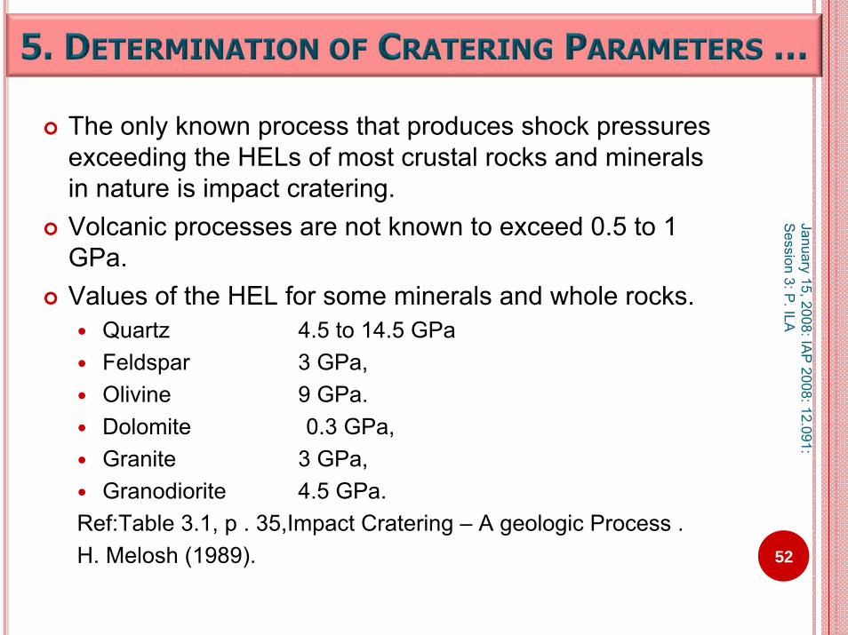
The only known process that produces shock pressures exceeding the HELs of most crustal rocks and minerals in nature is impact cratering. Volcanic processes are not known to exceed 0.5 to 1 GPa. Values of the HEL for some minerals and whole rocks.
Quartz 4.5 to 14.5 GPaFeldspar 3 GPa, Olivine 9 GPa. Dolomite 0.3 GPa, Granite 3 GPa,Granodiorite 4.5 GPa.
Ref:Table 3.1, p . 35,Impact Cratering – A geologic Process .H. Melosh (1989). 52
January 15, 2008: IAP
2008: 12.091: S
ession 3: P. ILA

Hugoniot Equations …
The parameters of the one-dimensional flow behind a planar shock wave are obtained by application of the conservation laws of mass, momentum, and energy across this wave.By choosing a coordinate system fixed in the undisturbed medium, one may derive the familiar Rankine-Hugoniot equations
53
January 15, 2008: IAP
2008: 12.091: S
ession 3: P. ILA

Hugoniot EquationsFor a thermodynamical treatment of shock fronts travelling through
matter, the so-called Hugoniot equations are used (Ref: Melosh, 1989).
These equations link uncompressed (initial) the pressure P,internal energy E, density ρ in front of a shock wave
to the values after the shock.
The density is also expressed as the specific volumes V = 1/ ρ and V0 = 1/ ρ 0 for the compressed and uncompressed cases, respectively
Uncompressed: P0, E0, ρ 0) are linked to values after the shock front compressed: P, E, ρ. 54
January 15, 2008: IAP
2008: 12.091: S
ession 3: P. ILA

Hugoniot Equations …Initial pressure, energy, and density before the shock are known values, while the respective values after the shock are unknown quantities, as are the shock velocity U and particle velocity up behind the shock front. The Hugoniot equations are then written as:
ρ(U - up) = ρ0 UP - P0 = ρ0 upUE - E0 = (P + P0)(V0 - V)/2 where V = 1/ ρ and V0 = 1/ ρ0 are compressed and uncompressed specific (per unit mass) volumes, ρ and ρ0 are compressed and uncompressed densities, E0 and E are the specific internal energies; and P0 and P are pressures in front of and behind the shock front.
55
January 15, 2008: IAP
2008: 12.091: S
ession 3: P. ILA
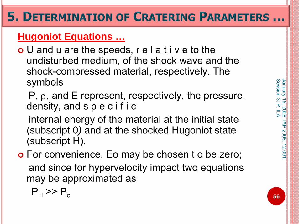
Hugoniot Equations …U and u are the speeds, r e l a t i v e to the undisturbed medium, of the shock wave and the shock-compressed material, respectively. The symbolsP, ρ, and E represent, respectively, the pressure, density, and s p e c i f i cinternal energy of the material at the initial state (subscript 0) and at the shocked Hugoniot state (subscript H). For convenience, Eo may be chosen t o be zero; and since for hypervelocity impact two equations may be approximated asPH >> Po 56
January 15, 2008: IAP
2008: 12.091: S
ession 3: P. ILA

Hugoniot Equations …The factors that effect the observed shock effect and consequently effect the Hugoniot equation- of-state of minerals and rocks are:initial volume of porositygrain sizemodal mineral compositionshock impedancethermal conductivity of surrounding phasespresence of voidswater content
57
January 15, 2008: IAP
2008: 12.091: S
ession 3: P. ILA

Hydrodynamic computer codes (hydrocodes) are powerful numerical tools for simulating the dynamics of continuous media.
Several hydrocodes are developed from simple to complex impact cratering simulations involving phase changes and multiple materials.
58
January 15, 2008: IAP
2008: 12.091: S
ession 3: P. ILA
Hydrocodes are developed to study variousimpact parameters such as
viscous fluid flow elastic and plastic deformationtensile failurecrater collapsedynamic fragmentation during an impactSpallationatmospheric breakup of meteoroids during atmospheric entry.
59
January 15, 2008: IAP
2008: 12.091: S
ession 3: P. ILA

Examples of Hydrocode modeling programs:Earth Impact Effects Program: A Web-based computer program for calculating the regional environmental consequences of a meteoroid impact on EarthG. S. Collins, H. J. Melosh, R. A. Marcus,Meteoritics & Planetary Science, 2005, v. 40, Nr. 6, 817–840.SALE 2 is an extensively modified version of SALESALE : Simplified Arbitrary Lagrangian-Eulerian computer program,A. A. Amsden, H.M. Ruppel, C.W. Hirt, SALE: A Simplified ALE computer program for fluid flow at all speeds, Los Alamos National Laboratory Report LA-8095, 1980.C. E. Anderson Jr., An overview of the theory of hydrocodes,International Journal of Impact Engineering, 1987, v. 5, 33-59.
60
January 15, 2008: IAP
2008: 12.091: S
ession 3: P. ILA

Energy of the impactor (meteorite)
E = (1/2) miv02 = (Π/12)ρi L0
3v02
L0 is the impactor diameter at the top of the atmosphere, v0 is the velocity of the impactor at the top of the atmosphere,
Other necessary parameters are:ρi is the impactor density, ρt is the target density, Θ is the angle subtended between the impactor’s trajectory and the tangent plane to the surface of the Earth at the impact pointr is distance from the impact site at which the environmental consequences are determined is measured along the surface of the EarthΔ isthe epicentral angle Δ between the impact point and thisRE is the radius of the Earth. distance r is given by Δ = r/RE
61
January 15, 2008: IAP
2008: 12.091: S
ession 3: P. ILA

a) the impactor of initial diameter L0 begins to break up at a certain altitude; from then onwards because of different pressures on the front and back face the impactor spreads perpendicular to the trajectory.b) the impactor breaks up but the critical impactordiameter is not attained before the fragmented impactor strikes the surface.
Schematic illustration of two atmospheric entry scenarios considered in the Earth Impact Effects Program could be found in the reference.
62
January 15, 2008: IAP
2008: 12.091: S
ession 3: P. ILA

Salient features of the Web program modeling of environmental effects of impact on Earth consists of
Impact energy and recurrence intervalCrater dimensions and melt productionThermal radiationSeismic effectsEjecta depositAir blastEffect of water layerGlobal effects …
Ref: Earth Impact Effects Program: A Web-based computer program for calculating the regional environmental consequences of a meteoroid impact on Earth,G. S. Collins, H. J. Melosh, and R. A. Marcus,Meteoritics & Planetary Science 40, Nr 6, 817–840 (2005) 63
January 15, 2008: IAP
2008: 12.091: S
ession 3: P. ILA

Melt volume produced during the impact event, based on tresults of numerical modeling of the early phase of the impevent is studied by several authors.O’Keefe and Ahrens1982b, Grieve and Cintala 1992,Pierazzo et al. 1997, Pierazzo and Melosh, 2000,
Assumptions are: 1) the impact velocity is in excess of ~12 km s−1 (the threshold velocity for significant target melting, O’Keefe anAhrens 1982b); 2) the density of the impactor and target are comparable; a3) all impacts are vertical, these data are well-fit by the simexpression:
he act
d
nd ple
64
January 15, 2008: IAP
2008: 12.091: S
ession 3: P. ILA

Interaction of matter under impact“ Matter is being accelerated very rapidly and,
the resulting stress wave will become a shock wave moving at supersonic speed (up to about 2/3 of the impact velocity). Shock waves are inherently nonlinear and shock fronts are abrupt. They can be mathematically represented as a discontinuous jump of pressure, density, particle velocity, and internal energy. In reality, shock waves have a finite thickness, up to a few meters in rocks, depending on their porosities.”
65
January 15, 2008: IAP
2008: 12.091: S
ession 3: P. ILA

Crater Dimensions and Melt production ModelingDetermining the size of the final crater from a given impactorsize, density, velocity, and angle of incidence is a complex task. The main difficulty in deriving an accurate estimate of the final crater diameter is that no observational or experimental data are present for impact craters larger than a few tens of meters in diameter. Hence modeling is required.Sophisticated numerical models capable of simulating
the propagation of shock waves, the excavation of the transient crater, the subsequent collapse
are needed66
January 15, 2008: IAP
2008: 12.091: S
ession 3: P. ILA

Laboratory experiments reveal that, at low pressures and temperatures (well below melting), the yield strength of rock materials may be considered to have two components,
a cohesive strength that is independentof overburden pressure, a frictional component that is a function of overburden pressure and, hence, depth.
(Lundborg, 1968). The scaling laws are useful to extend the capabilities of the laboratory experiments. 67
January 15, 2008: IAP
2008: 12.091: S
ession 3: P. ILA

SCALING LAWSA set of scaling laws that extrapolate the results of small-scaleexperimental data to scales of interest or extend observationsof cratering on other planets to the Earth can be used.
The Scaling law is based on the works of Gault (1974),Holsapple and Schmidt (1982), Schmidt and Housen (1987), and combines a wide range of experimental cratering data such assmall-scale hypervelocity experiments and nuclearexplosion experiments
The equation relates the density ofthe target ρt and impactor ρi (in kg m−3), the impactor diameter after atmospheric entry L (in m), the impact velocity at the surface vi (in m s−1), the angle of impact θ (measured to the horizontal), andthe Earth’s surface gravity gE (in m s−2 ).
68
January 15, 2008: IAP
2008: 12.091: S
ession 3: P. ILA

A simple case:Living bones contain U around 100 ppb (0.1 ppm).Say we come across a fossilized tooth or bone With U in that 1 – 15 ppm.
What does that mean?
69
January 15, 2008: IAP
2008: 12.091: S
ession 3: P. ILA

This means that bones and teeth are enriched in U during fossilization.U comes from ground water or interstitial water in archaeological layers.
Possible assumptions in the analysisThe introduction of the U is effective shortly after death U is introduced continuously and slowly, then the analysis will have additional parameters to be considered.
70
January 15, 2008: IAP
2008: 12.091: S
ession 3: P. ILA

Stable and radioactive isotope measurements provide excellent tools for the determination of age of an event or formation etc.Radioactive isotopes decay continuously at a constant rate.
This is expressed as N = No e-λt
Where N is the number of parent nuclei existing at time t in terms of initial number of nuclei No .
Where λ is the decay constant = ln 2/ T1/2 .T1/2 = Half life of the radioisotope.
Ref: Montigny, R., The conventional Potassium-Argon Method, p. 295-321 in Nuclear Methods of Dating
71
January 15, 2008: IAP
2008: 12.091: S
ession 3: P. ILA

No - N = N (e-λt - 1)
The value of t can be derived for a series of measurements of (No - N )
Radioactive isotopes for age studies may be distinguished into two types:
1) Primitive and 2) CosmogenicPrimitive: radioisotopes that have existed since the
formation of the Earth147Sm, 238UCosmogenic: Continuously generated.39Ar, 14C, 36Cl 72
January 15, 2008: IAP
2008: 12.091: S
ession 3: P. ILA
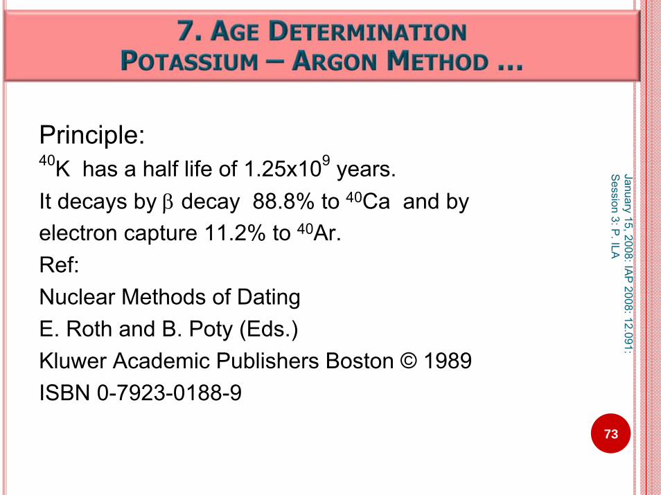
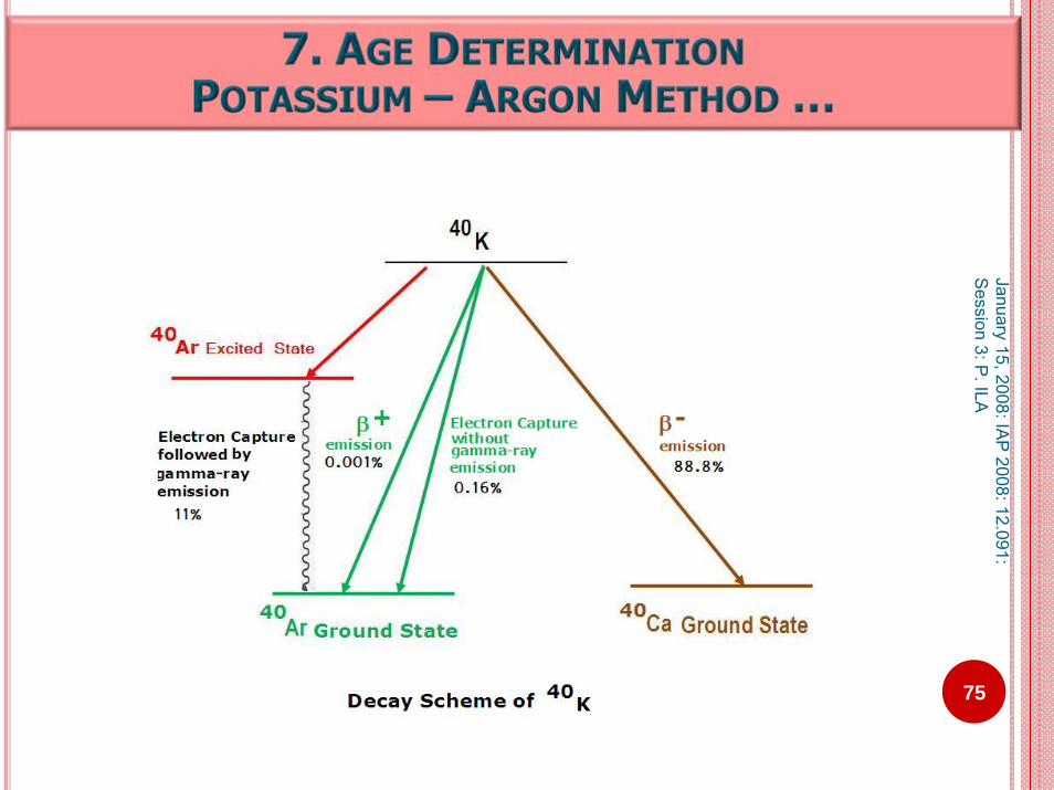
Principle:40K has a half life of 1.25x10⁹ years.It decays by β decay 88.8% to 40Ca and by electron capture 11.2% to 40Ar.Ref:Nuclear Methods of DatingE. Roth and B. Poty (Eds.)Kluwer Academic Publishers Boston © 1989ISBN 0-7923-0188-9
73
January 15, 2008: IAP
2008: 12.091: S
ession 3: P. ILA

Review notes:During beta-minus decay, a neutron of the nucleusbecomes a proton, an electron and an antineutrino. During beta-plus decay, a proton of the nucleus becomes neutron, a positron and a neutrino. Although the numbers of protons and neutrons in an atom's nucleus change during beta decay, the total number of particles (protons + neutrons) remains the same.
Electron Capture:The process in which an atom or ion passing through
a material medium either loses or gains one or more orbital electrons.
74
January 15, 2008: IAP
2008: 12.091: S
ession 3: P. ILA
75
January 15, 2008: IAP
2008: 12.091: S
ession 3: P. ILA

76
January 15, 2008: IAP
2008: 12.091: S
ession 3: P. ILA
The age equation is given by
where λε refers to the decay of 40K to 40Arλβ refers to the decay of 40K to 40Ca*40Ar is radiogenic argon, produced by in situ decay of 40KFor further details refer toMontigny, R., The conventional Potassium-Argon Method, p. 297 inNuclear Methods of Dating

77Ref: Schematic is based on Figure 2, Montigny, R., The conventional Potassium-Argon Method, p. 299 in Nuclear Methods of Dating.
January 15, 2008: IAP
2008: 12.091: S
ession 3: P. ILA

78
January 15, 2008: IAP
2008: 12.091: S
ession 3: P. ILA
The analyzed argon consists of three components:1) Radiogenic argon 40Arrad ,2) The trace ArT3) Atmospheric contamination Atatm
The values of components ArT and Atatmare known, hence 40Arrad can be calculated.
From this, the age of the sample can be calculated, (as shown in the next slide).
Ref: Montigny, R., The conventional Potassium-Argon Method, p. 300 in Nuclear Methods of Dating
Argon Analysis is done currently by isotope dilution and mass spectrometry
The procedure consists of1.A known amount of a rock or mineral is melted in a
molybdenum crucible inserted in a high vacuum system.
2.When melting , a known amount of almost 99% enriched 38Ar is added to gases extracted from the sample.
3.The mixture is purified by removal of oxygen, hydrogen, nitrogen and carbon dioxide.
79
January 15, 2008: IAP
2008: 12.091: S
ession 3: P. ILA

4. The rarefied gases are introduced into mass spectrometer
5. 40Ar/38Ar and 38Ar/36Ar are measured.6. The fraction of atmospheric argon 38Ar can be
obtained from 38Ar/36Ar of the atmosphere. 7. 40Ar/36Ar = 295.5 (known).8. The radiogenic 40Ar of the sample is calculated.9. 40Arrad: number of 40Ar atoms in the sample
38ArT : number of 38Ar atoms of the tracerM means measured ratio; ‘a’ means atmospheric ratio
80
January 15, 2008: IAP
2008: 12.091: S
ession 3: P. ILA

Potassium Analysis:K concentrations can be determined by one of the
methods:1) Flame spectrophotometry2) Atomic Absorption3) Neutron Activation4) Isotope Dilution5) Mass spectrometry
81
January 15, 2008: IAP
2008: 12.091: S
ession 3: P. ILA

82
decay constant of 40K to 40Arλε = 0.581x10⁻¹⁰ y-1
decay constant of 40K to 40Caλβ = 4.962x 10⁻¹⁰y-1
Knowing all the parameters, namely, *40Ar, 40K, λε, λβon the right hand side of the equation, age of thesample can be determined.Ref: Montigny, R., The conventional Potassium-Argon Method, p. 302 in Nuclear Methods of Dating
January 15, 2008: IAP
2008: 12.091: S
ession 3: P. ILA
INTRODUCTION & CONCEPTSAnalytical technique is a tool to determine
abundances of elementsinformation about mineralsinformation about organics
May be categorized asinorganic and organicqualitative and quantitativespectroscopic and classical
January 15, 2008: IAP 2008: 12.091: Session 3: P. ILA
83

INTRODUCTION & CONCEPTS …Qualitative means – identification. Quantitative means - determining the abundance.The basic concept of quantitative analysis:Take a material, with known abundances, called the standard.Using the known amount of abundance(s) in the standard, estimate the abundance(s) in the unknown called the sample, maintaining all the conditions and parameters same for the sample and the standard.
January 15, 2008: IAP 2008: 12.091: Session 3: P. ILA
84
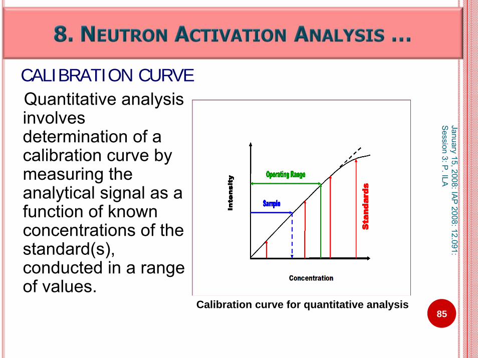
CALIBRATION CURVEQuantitative analysis involves determination of a calibration curve by measuring the analytical signal as a function of known concentrations of the standard(s), conducted in a range of values.
January 15, 2008: IAP
2008: 12.091: S
ession 3: P. ILA
85Calibration curve for quantitative analysis
The different energies of the photons in the electromagnetic spectrum are representative of different types of interactions in the atoms and molecules; and are detected and measured by different types of spectroscopic techniques.Microwave and infrared spectroscopy use the properties of molecular rotations and vibrations.Ultra violet and visible light spectroscopy utilize absorption and emission of energies of outer electron transitions.X-ray fluorescence – inner electronsGamma rays – nuclear transitions.
January 15, 2008: IAP
2008: 12.091: S
ession 3: P. ILA
86
SPECTROSCOPIC TECHNIQUES …

January 15, 2008: IAP
2008: 12.091: S
ession 3: P. ILA
87
PICTORIAL DEPICTION OF ATOMIC NUCLEUS – ELECTRON ORBITALS
K shell orbital (2 electrons)
L shell orbital (8 electrons)
M shell orbital (18 electrons)
Nucleus

Neutron irradiation
A stable isotope when bombarded with neutrons, absorbs a neutron; and by the most common type of nuclear reaction, namely, (n, gamma) reaction, gets transformed into higher mass unstable nucleus.
A * A+1X (n,γ) X X
Z N (unstable) Z N+1
When the unstable nucleus de-excites by prompt gamma rays, and gets transformed into a radioactive nucleus (with next higher neutron number). This radioactive nucleus decays mainly by beta rays and (or) characteristic gamma-rays.
January 15, 2008: IAP 2008: 12.091: Session 3: P. ILA
88

Nuclear ReactionNuclear reaction occurs when target nuclei are bombarded with nuclear particles, depicted pictorially
X + a Y + b + QOr
X(a,b)Y
Target X is bombarded by particle “a”,Y is the product nuclei with resulting particle “b” .Q is the energy of the nuclear reaction, which is the difference between the
masses of the reactants and the products.Ex:
59Co + 1n 60Co + γ27 32 0 1 27 33
or59Co (n, γ) 60Co
27 32 27 33
January 15, 2008: IAP
2008: 12.091: S
ession 3: P. ILA
89

Principle:Neutron Activation Analysis is a nuclear analytical technique that involves irradiatinga sample with neutrons. The stable isotopes of different elements in the samplebecome radioactive. The radioactivity of different radionuclides can be detected and quantified by gamma spectroscopy.
January 15, 2008: IAP 2008: 12.091: Session 3: P. ILA
90
ANALYSIS OF SOLIDS BYNEUTRON ACTIVATION ANALYSIS (NAA) AND GAMMA SPECTROSCOPY

Neutron capture:The target nucleus absorbs (captures) a neutron resulting in a product isotope, the mass number of which is incremented by one. If the product nucleus is unstable, it usually de-excites by emission of gamma rays and/or β. Ex:
58Fe (n, γ) 59Fe .26 32 26 33
January 15, 2008: IAP 2008: 12.091: Session 3: P. ILA
91

An irradiated material is radioactive emitting radiations –α, β, γ, ………
For Neutron Activation Analysis – usually gamma radiation is selected.
Gamma spectrometer is the detection system that measures gamma ray intensity.
92
GAMMA SPECTROMETER
January 15, 2008: IAP 2008: 12.091: Session 3: P. ILA

Gamma spectrometer system formeasuring the gamma-ray activity of an irradiated material consists typically 1) Detector2) Amplifier3) Multi Channel Analyzer4) Computer & peripheralsThis is shown pictorially in the next slide.
January 15, 2008: IAP 2008: 12.091: Session 3: P. ILA
93
GAMMA SPECTROMETER

January 15, 2008: IAP
2008: 12.091: S
ession 3: P. ILA
94
Gamma Spectroscopy System

The energy of nuclear radiation is convertedinto an electrical signal by a device that is the nuclear radiation detector.The three major categories of gammadetectors used in Neutron Activation Analysis
are:1)Scintillators : NaI(Tl), CsF, ZnS(Ag)2)Semiconductors : Si, Ge, CdTe, GaAs3)Gas Filled : He, Air, H2, N2
January 15, 2008: IAP 2008: 12.091: Session 3: P. ILA
95
GAMMA DETECTOR…
The nuclear radiations emanating from the irradiated material will cause ionization in the detector medium by means of charged particle products of their interactions.
The scintillators and the semiconductors have energy discrimination capacity better than the gas filled detectors.
January 15, 2008: IAP 2008: 12.091: Session 3: P. ILA
96
GAMMA DETECTOR…

The nuclear radiations incident on the detector crystal initiate ionizations by creation of electrons (negative charge) and holes (positive charge).
An electric field is created by applying high voltage to the electrodes mounted on opposite sides of the detector crystal. The charge carriers get attracted to the electrodes of opposite polarity because of the electric field. The charge collected at the electrodes is proportional to the energy lost by the incident radiation.
A germanium detector system and a typical gamma spectrum are shown in the next two slides
January 15, 2008: IAP 2008: 12.091: Session 3: P. ILA
97
GAMMA DETECTORS…

January 15, 2008: IAP
2008: 12.091: Session 3:
P. ILA
98
Components of a Germanium Detector System
Ref: Knoll, G. F., Radiation detection and measurements.Debertin, K., and Helmer, R. G.,Gamma and X-ray spectrometry with semiconductor detectors

99
January 15, 2008: IAP
2008: 12.091: S
ession 3: P. ILA
Ref: P. Ila and P. Jagam, Journal of Radioanalytical and Nuclear Chemistry, 57 (1980) 205-210.

Source Gamma-ray Channel Energy Number keV
57Co 123.0 366
137Cs 661.64 1985
60Co 1173.21 35211332.48 3996
Energy C alib ration
366, 123.0
1985, 661.64
3521, 1173.213996, 1332.48
0
200
400
600
800
1000
1200
1400
0 500 1000 1500 2000 2500 3000 3500 4000
Channel Number
Gam
ma-
ray
Ener
gy(k
eV)
January 15, 2008: IAP
2008: 12.091: S
ession 3: P. ILA
100
Energy Calibration of a Gamma Spectrometer using Standard Calibration Sources

AStandard = Activity of an isotope of an element in the known (Standard) is proportional to the amount present.ASample = Activity of the isotope of the same element in the unknown (Sample)AmountStandard/ AmountSample= AStandard / AsampleAmountSample = AmountStandard * AStandard / Asampleassuming all the values of standard and sample are normalized to the same experimental conditions.
January 15, 2008: IAP 2008: 12.091: Session 3: P. ILA
101
COMPARATOR METHOD

January 15, 2008: IAP
2008: 12.091: S
ession 3: P. ILA
102
Trace Element Analysis of Impact Melt RocksInstrumental Neutron Activation Analysis
C1-N10-1 Y6-N19-P C1-N10-1 Y6-N19-Pppm Error ppm ppm Error ppm ppm Error ppm ppm Error ppm
Sc 16.6 0.2 12.4 0.1 La 21.9 0.3 23.3 0.3Cr 88 1 114 2 Ce 45.2 0.5 36.8 0.5Co 16.2 0.2 9.8 0.1 Nd 26 3 16 2Ni 30 8 20 8 Sm 4.53 0.07 3.05 0.04As 0.7 0.2 0.4 0.1 Eu 1.04 0.02 0.69 0.01Se <0.4 <0.3 Tb 0.72 0.01 0.42 0.01Br 3.1 0.3 1.2 0.1 Yb 2.69 0.04 1.71 0.03Rb 55 2 67 3 Lu 0.41 0.01 0.27 0.006Sr 336 18 640 30 Hf 3.84 0.06 2.61 0.05Zr 155 18 98 19 Ta 0.62 0.02 0.35 0.01Sb 0.11 0.01 0.22 0.01 W 1.1 0.4 1.7 0.3Cs 0.16 0.02 0.33 0.02 Ir (ppb) 6.0 0.7 <1.6Ba 701 17 745 17 Au (ppb) 40 2 17 1
Th 7.18 0.08 6.9 0.1U 2.0 0.1 3.05 0.09
Ref: Schuraytz et al (Geology, 1994, v. 22, p. 871, NASA-CR-203591)

ICPMS technique is useful for multi-element analysis of geological, environmental and medical sample materials.
ICPMS provides information about the abundancesas well as isotopic ratios of the nuclides.
January 15, 2008: IAP
2008: 12.091: Session 3: P
. ILA
103

Principle:The ICPMS technique consists of a high temperature plasma, into which the sample aerosol is injected and positively charged ionsare generated by the interaction. A mass spectrometer quantifies the ionization based on the mass to charge ratio.Knowing the concentration of an element (of corresponding isotope) in the standard, the unknown concentration in the sample is calculated.
January 15, 2008: IAP
2008: 12.091: S
ession 3: P. ILA
104

105
January 15, 2008: IAP
2008: 12.091: S
ession 3: P. ILA
Ref: P. J. Potts, Handbook of silicate Rock Analysis

Electron probe microanalysis technique is useful to analyze the composition of a selected surface area of diameter size of few microns (micron = 0.001 meter = 0.1 cm) of the sample.For example in geological materials – can determine
composition of individual mineralsvariation of concentration within a single grain
For this type of analysis – the samples are to be polished thin sections mounted
in a resin block, orglass slide backing..
January 15, 2008: IAP 2008: 12.091: Session 3: P. ILA
106

107
January 15, 2008: IAP
2008: 12.091: S
ession 3: P. ILA
Ref: P. J. Potts, Handbook of Silicate Rock Analysis

WAVELENGTH DISPERSIVE XRF (WDXRF)ENERGY DISPERSIVE XRF (EDXRF) …Principles:
In a stable atom, electrons occupy in discrete energy orbitals; the notation of these orbitals in decreasing binding energy level is K, L, M, … .The sample is excited by means electromagnetic radiation generated by radioisotopes, X-ray tubes, charged particles (electrons, protons and alpha particles).WDXRF use X-ray tubesEDXRF uses both X-ray tube and radio-isotopes.
January 15, 2008: IAP
2008: 12.091: S
ession 3: P. ILA
108

WAVELENGTH DISPERSIVE XRF (WDXRF)ENERGY DISPERSIVE XRF (EDXRF)
Dispersive means separation and measurement.WDXRF – Separation is done by collimators and diffraction crystals. Measurement is done by detecting the characteristic wavelengths by scintillation detectors and proportional counters providing a pulse height distributed spectrum. EDXRF – the wavelength dispersive crystal and detector system is replaced by solid state energy dispersive system consisting of Si(Li) detector coupled to a Multichannel analyzer system.
January 15, 2008: IAP
2008: 12.091: S
ession 3: P. ILA
109

January 15, 2008: IAP
2008: 12.091: S
ession 3: P. ILA
110
Major Element Analysis of Impact Melt RocksElectron Microprobe Analysis
C1-N10-1 Y6-N19-P% Error % % Error %
SiO2 64.4 0.40 61.7 0.50TiO2 0.53 0.02 0.36 0.01Al2O3 14.9 0.20 13.7 0.10FeO 4.60 0.10 3.83 0.02
MnO 0.09 0.01 0.08 0.01MgO 2.76 0.07 2.55 0.02CaO 5.50 0.10 10.01 0.09
Na2O 3.71 0.05 2.54 0.02K2O 2.72 0.03 2.27 0.03P2O3 0.13 0.01 0.09 0.01SO3 0.07 0.01 0.08 0.01Sum 99.4 97.2
Ref: Schuraytz et al (Geology, 1994, v. 22, p. 871, NASA-CR-203591)

January 15, 2008: IAP
2008: 12.091: S
ession 3: P. ILA
111
Amsden, A. A., Ruppel, H. M., Hirt, C. W., SALE: A simplified ALE computer program for fluid flow at all
speeds,Los Alamos National Laboratories LA-8095: 101 pp, 1980.
Anderson Jr . C. E .,An overview of the theory of hydrocodes,International Journal of Impact Engineering 1987, v.5, 33-59 .
Collins, G. S., Melosh, H. J., Robert A. Marcus, R. A.,Earth Impact Effects Program: A Web-based computer program for calculating the regional environmental consequences of a meteoroid impact on Earth,Meteoritics & Planetary Science, 2005, v. 40, Nr. 6, 817–840.

Dean, J. R.,Practical inductively coupled plasma spectroscopy, Hoboken, NJ : Wiley, 2005.ISBN: 978-0-470-09348
Debertin, K., and Helmer, R. G.,Gamma and X-ray spectrometry with semiconductor detectors,New York: North Holland 1988ISBN: 0444871071.
112
January 15, 2008: IAP
2008: 12.091: S
ession 3: P. ILA
Deutsch, A.,Isotope Systematics Support the Impact Origin of theSudbury Structure (Ontario, Canada). Large Meteorite Impacts and Planetary Evolution,GSA Special Paper 1994, 293, 348 pp.ISBN:0813723841.
Ewing’s Analytical Instrumentation Handbook,3rd Edition,Editor: J. Gazes,New York: Marcel Dekker, c 2005
French, B.M. , 1998, Traces of Catastrophe, Lunar and Planetary Institute, Houston, Tx, 120 pp.,LPI Contribution No. 954. 113
January 15, 2008: IAP
2008: 12.091: S
ession 3: P. ILA
Gault D. E.,Impact cratering; in A primer in lunar geology, edited by Greeley R. and Shultz P. H. Moffett Field: NASA Ames Research Center. 1974, pp. 137–175.
Glass, B. J., Domville, S., and Lee, P.,Further Geophysical Studies of the Haughton Impact Structure,Lunar and Planetary Science XXXVI (2005).http://ti.arc.nasa.gov/publications/pdf/0953.pdf
Grieve, R. A. F., Cintala, M. J., An analysis of differential impact melt-crater scaling and implications for the terrestrial impact record, Meteoritics, 1992, v. 27, p. 526-538.
114
January 15, 2008: IAP
2008: 12.091: S
ession 3: P. ILA

Grauch, V. J. S. High-Resolution Aeromagnetic Survey to Image Shallow Faults, Dixie Valley Geothermal Field, Nevada, USGS Open File Report ofr-02-0384_508.pdf
Grieve, R.A.F. and L.J. Pesonen,The Terrestrial Impact Cratering Record, Tectonophysics, 1992, v. 216, 1-30.
Holsapple and Schmidt,Point Source Solutions and Coupling Parameters in Cratering Mechanics. Journal of Geophysical Research, 1987, v. 92, 6350-6376.
115
January 15, 2008: IAP
2008: 12.091: S
ession 3: P. ILA

Ila, P., and Jagam, P. ,Multielement analysis of food spices by instrumentalneutron activation analysis, Journal of Radioanalytical and Nuclear Chemistry,1980, v. 57, p. 205-210.
Jagam, P., and Muecke,G. K., Chapter IV : Instrumentation in neutron activation analysis, pages 73-108,Mineralogical Association of CanadaShort Course in Neutron Activation Analysis in the Geosciences,Halifax May 1980, Ed: G. K. Muecke
Keary, P. and Brooks, M.,Introduction to Geophysical Exploration,(2nd edition) Blackwell Scientific Publishing, 1991, ISBN 0632029234
116
January 15, 2008: IAP
2008: 12.091: S
ession 3: P. ILA
Knoll, G. F.,Radiation detection and measurementsNew York: John Wiley & Sons, 1979,
ISBN: 047149545XKoeberl, C., Impact cratering: The mineralogical and geochemical evidence. In: Proceedings, "The Ames Structure and Similar Features", Editors: K. Johnson and J. Campbell, Oklahoma Geological Survey Circular 1997, 100, 30-54.Lowrie, W. , Fundamentals of Geophysics,
Cambridge University Press (October 13, 1997),ISBN: 0521467284
117
January 15, 2008: IAP
2008: 12.091: S
ession 3: P. ILA

Lundborg, N., Strength of rock-like materials. Int. J. Rock Mech. Min. Sci., 1968, v. 5, 427-454.
Mark, K., (1987), Meteorite Craters,The University of Arizona Press. 288 pp.ISBN-10: 0816509026,ISBN-13: 9780816509027
118
January 15, 2008: IAP
2008: 12.091: S
ession 3: P. ILA

Melosh, H.J. (1980), Cratering Mechanics - Observational, Experimental, and Theoretical. The Annual Review of Earth and Planetary Sciences, 1980, v. 8, 626 pp.
Melosh, H.J., (1985),Impact Cratering Mechanics: Relationship between the Shock Wave and Excavation Flow,Icarus, 1985, v. 62, p. 339-343.
Melosh, H. J. (1989), Impact Cratering. New York: Oxford University Press, © 1989, 245 pp.ISBN 0195042840 119
January 15, 2008: IAP
2008: 12.091: S
ession 3: P. ILA

Middleton, G.V. and Wilcox, P.R., Mechanics in the earth and environmental sciences, New York, Cambridge University Press, © 1994, 459 pp.ISBN: 9780521446693Montigny, R. The conventional Potassium-Argon Method, p. 295-321 in Nuclear Methods of Dating,E. Roth and B. Poty (Eds.)Kluwer Academic Publishers Boston © 1989,ISBN 0-7923-0188-9. 120
January 15, 2008: IAP
2008: 12.091: S
ession 3: P. ILA

Morrison, R. H.,Simulation of meteoroid velocity impact by use of dense projectiles, NASA Technical Note TN – D5734, April1970.
Nininger, H.H. (1961). Ask a Question about Meteorites, 87pp.Amer Meteorite Lab,ISBN-10: 0910096031,ISBN-13: 978-0910096034.
Norman, M.D. , Sudbury Igneous Complex: Impact Melt or Endogenous Magma? Implications for Lunar Crustal Evolution. Large Meteorite Impacts and Planetary Evolution,GSA Special Paper, 1994, 293, 348 pp.ISBN 0-9665869-3-X
121
January 15, 2008: IAP
2008: 12.091: S
ession 3: P. ILA

O'Keefe, J.D. and T.J. Ahrens (1994). Impact-Induced Melting of Planetary Surfaces, Large Meteorite Impacts and Planetary Evolution GSA Special Paper 293, 348 pp,ISBN:0813723841
Pierazzo,E., Collins, G., A brief introduction to hydrocode modeling of impact cratering, In: Dypvik,D., Burchell,M., Claeys,P., editor, Crateringin marine environments and on ice, New York, Springer, 2004, Pages: 323 - 340, ISBN: 3-5404-0668-9
122
January 15, 2008: IAP
2008: 12.091: S
ession 3: P. ILA

Pierazzo E, Melosh HJ (2000a), Hydrocode modeling of oblique impacts: The fate of the projectile, Meteoritics and Planetary Science 35: 117-130. Pierazzo E, Melosh HJ (2000b), Melt production in oblique impacts, Icarus 145: 252-261. Pierazzo E, Melosh HJ (2000c),Understanding oblique impacts from experiments, observations, and modeling, Annual Review of Earth and Planetary Science 28: 141-167.
123
January 15, 2008: IAP
2008: 12.091: S
ession 3: P. ILA
Potts, P. J.,A handbook of silicate rock analysis,New York: Blackie, Chapman and Hall, 1987,ISBN: 0-412-00881-5 (U.S.A.).
Reid A.B. , Aeromagnetic Survey Design,Geophysics, (May 1980) Vol. 45, No.5, p. 973-976.
Schmidt R. M. and Housen K. R.,Some recent advances in the scaling of impact and explosion cratering, International Journal of Impact Engineering, 1987, v. 5, 543–560. 124
January 15, 2008: IAP
2008: 12.091: S
ession 3: P. ILA

Schuraytz, B. C., Sharpton, V. L., Marin, L. E.,Petrology of impact-melt rocks, at Chicxulubmultiring basin, Yucatan, Mexico,Geology, 1994, v. 22, p. 868 – 872, NASA-CR-203591.
Skoog, D. A., West, D. M., Holler, F. J.,Fundamentals of Analytical Chemistry, Sixth Edtion. New York, Saunders College Publishing,Harcourt Brace Jovanovich College Publisher,ISBN: 0-03-074922-0.
Stoffler, D. and A. Deutsch (1994). The formation of the Sudbury Structure, Canada: Toward a unified impact model,Large Meteorite Impacts and Planetary Evolution GSA Special Paper 293, 348 pp.,ISBN 0-9665869-3-X. 125
January 15, 2008: IAP
2008: 12.091: S
ession 3: P. ILA

126
January 15, 2008: IAP
2008: 12.091: S
ession 3: P. ILA


