University of Colorado Time Systems
Lucas BuccafuscaSean DesMarteauTanner Hannam
Jeff LassenJoshua Yang
Project Overview Functional Description of Parts and Interfaces Specifications Network Structure Description of Software Preliminary Parts List Division of Labor Schedule Questions
Contents
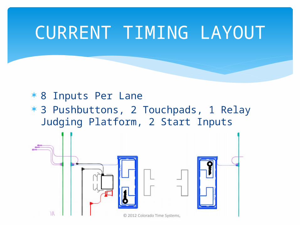
8 Inputs Per Lane 3 Pushbuttons, 2 Touchpads, 1 Relay Judging
Platform, 2 Start Inputs (Speaker/LEDs on Start Block)
CURRENT TIMING LAYOUT
CURRENT TIMING LAYOUT
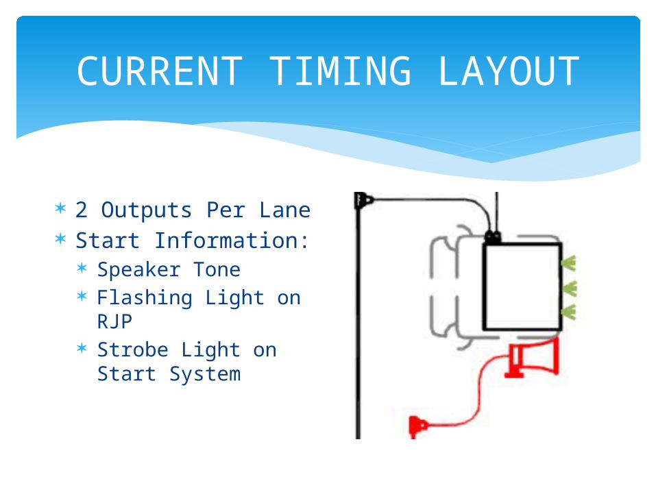
2 Outputs Per Lane Start Information:
Speaker Tone Flashing Light on RJP Strobe Light on Start
System
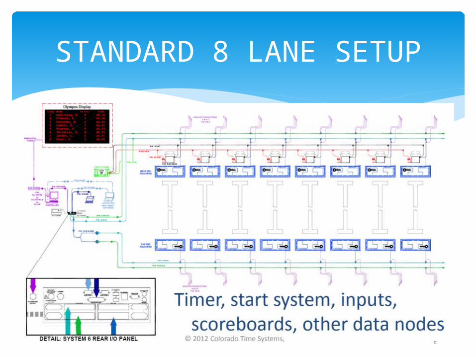
STANDARD 8 LANE SETUP
While current system is satisfactory it provides downsides. TOO MANY WIRES!!!! Very elaborate setup Wires/touchpads can be easily ruined by
water/human handling if not cared for properly Therefore an upgraded system is desired to
combat these downsides
DOWNSIDES TO CURRENT SYSTEM
Project Scope
Evolve from Wired Connections
Precise timing relations through copper connections
Need for conduits and elaborate setup To wireless input and output nodes
Mesh network synchronized to 1 msec Easy setup
Objectives
Create system of 80+ wireless nodes to account for all inputs/outputs per lane for 10 lane pool
Test for accuracy and reliability of system under normal race/pool conditions
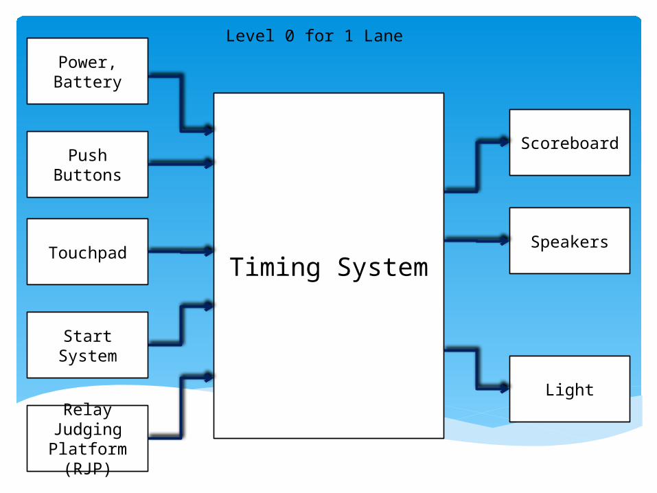
Timing System
Push Buttons
Power, Battery
Start System
Relay Judging Platform
(RJP)
Scoreboard
Speakers
Light
Touchpad
Level 0 for 1 Lane
Push
B
utt
ons
Pow
er,
B
att
er
y
Sta
rt
Syst
em
Rela
y
Jud
gin
g
Pla
tform
(R
JP)
Com
pute
r/
Sco
reboar
d
Speake
rs
Light
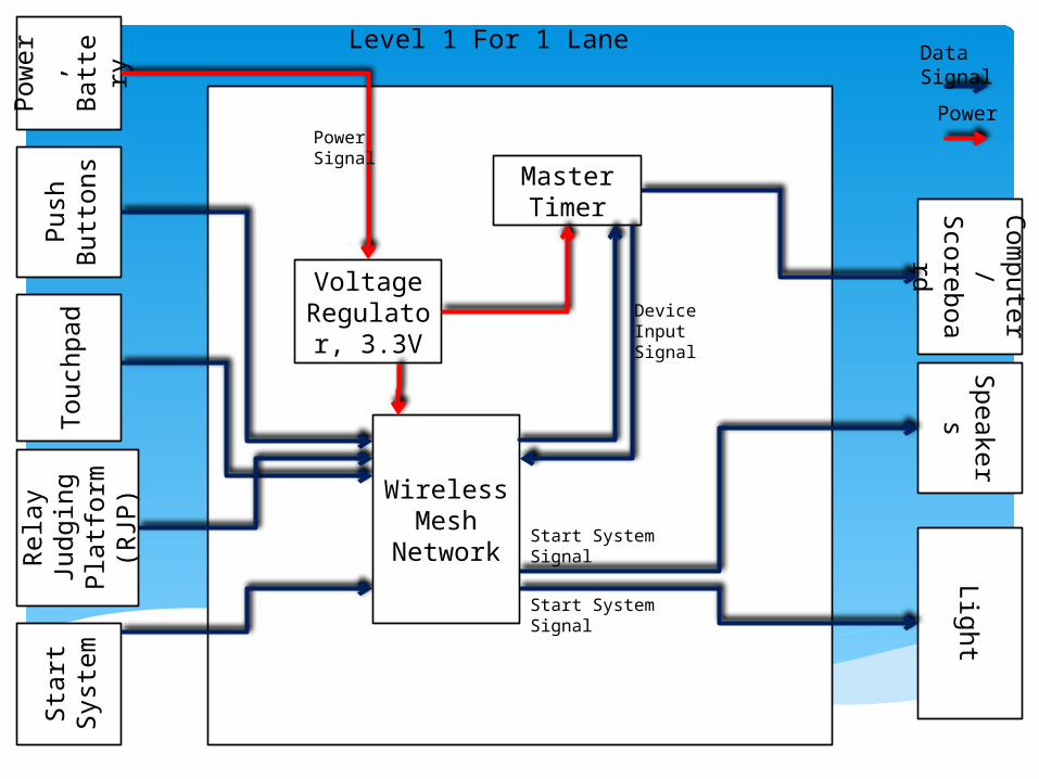
Voltage Regulator
, 3.3V
Wireless Mesh
Network
MasterTimer
Touch
pad
Start System Signal
Start System Signal
Device Input Signal
Power Signal
Level 1 For 1 LaneData Signal
Power
Push
B
utt
ons
Pow
er,
B
att
ery
Sta
rt
Syst
em
Rela
y
Jud
gin
g
Pla
tform
(R
JP)
Sco
reboar
dSp
eake
rsLig
ht
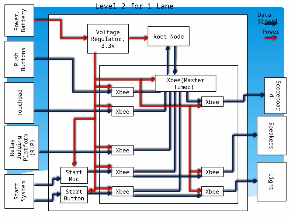
Voltage Regulator,
3.3V
Touch
pad
Level 2 for 1 Lane
Xbee
Xbee
Xbee
Xbee
Xbee
Xbee
Xbee
Start Mic
Start Button
Xbee
Xbee Xbee(Master Timer)
Data Signal
PowerRoot Node
Push
B
utt
ons
Pow
er,
B
att
ery
Sta
rt
Syst
em
Rela
y
Jud
gin
g
Pla
tform
(R
JP)
Sco
reboard
Sp
eake
rsLig
ht
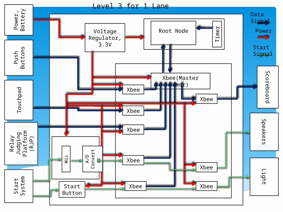
Voltage Regulator,
3.3V
Touch
pad
Level 3 for 1 Lane
Xbee
Xbee
Xbee
Xbee
Xbee
Xbee
Xbee Start Button
Xbee
Xbee(Master Timer)
A/D
C
onvert
or
Mic
Tim
er
Root Node
Data Signal
Power
Start Signal
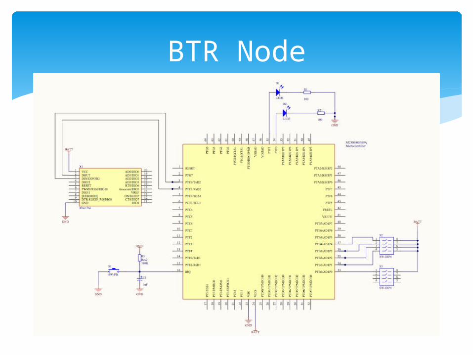
BTR Node
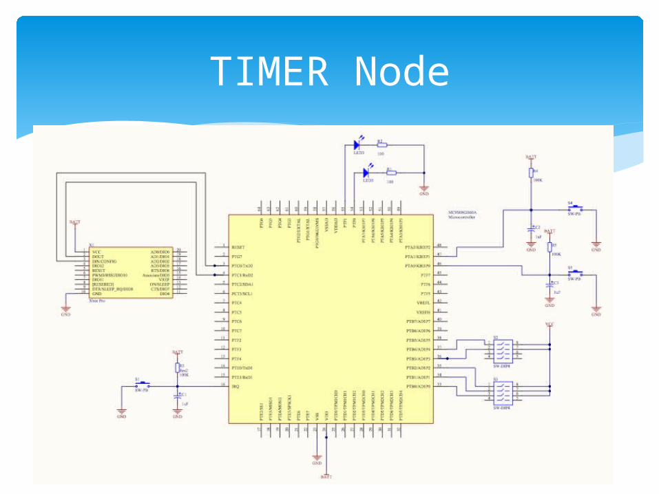
TIMER Node
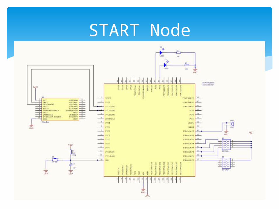
START Node
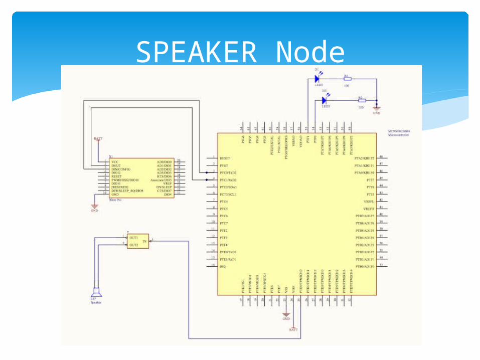
SPEAKER Node
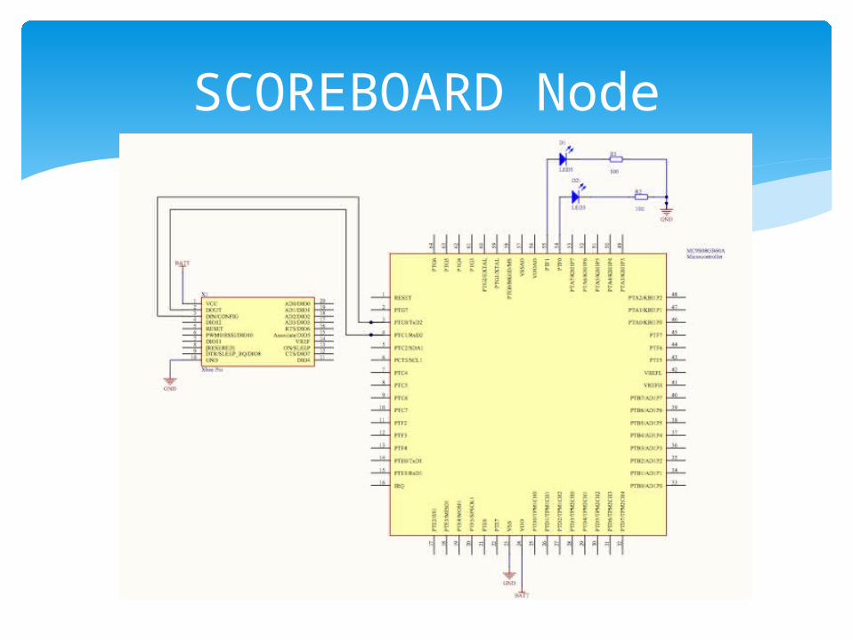
SCOREBOARD Node
Network Structure
Network orientation will be a Wireless Mesh Network (WMN)
Properties of a WMN include: Ability to Self-form/Self-heal (meaning that as
we add nodes to the network, we are able to wirelessly seam them together without trouble)
Relatively stable topology Data can reach the final destination in a
relatively fast amount of time
Network Setup
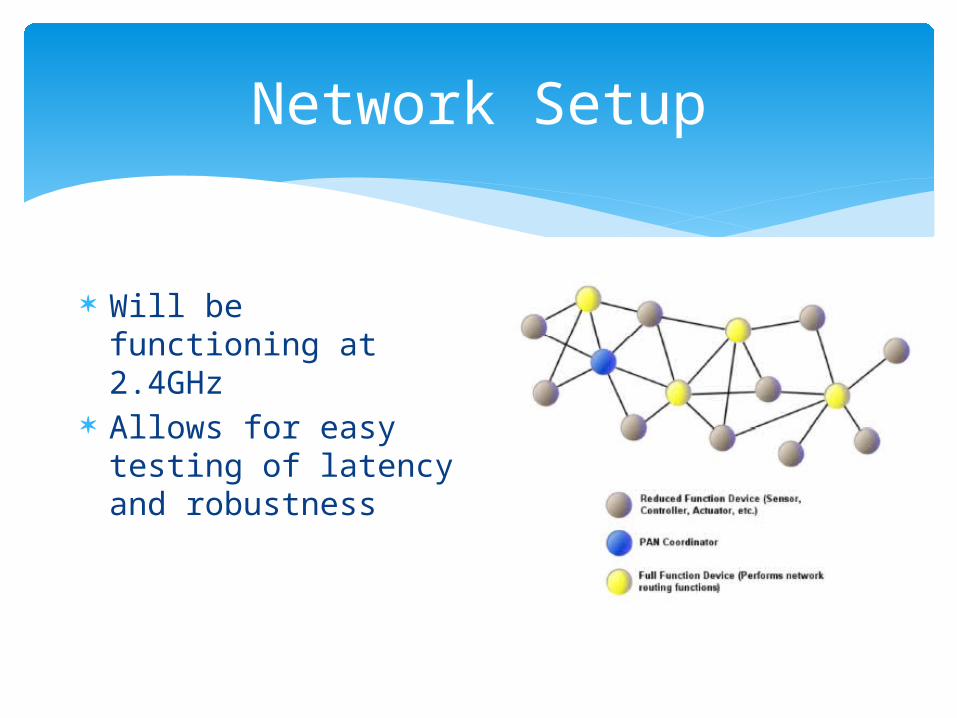
Will be functioning at 2.4GHz
Allows for easy testing of latency and robustness
Network Setup
Initial Wireless Synchronization will be implemented with Timing-sync Protocol for Sensor Networks (TPSN)
Offers distinct advantages to other wireless systems
Average Error due to propagation is relatively constant as more nodes are added
Requires fewer messages sent, and is more energy efficient.
TPSN Setup
Consists of two stages: Network Discovery and Synchronization
Discovery Phase:
The level discovery phase is run on network deployment. First, the root node is assigned. Once the root node is determined, it will initiate the level discovery.
The neighbors of the root node will then assign themselves as level 1. They will in turn send out the level_discovery packet to their neighboring nodes. This sequential labeling of nodes continues until all nodes are given a level
After the discovery phase, there is a moment where any nodes that are expected to be in the network that may have failed communication can reconnect
Synchronization Phase
The basic concept of the synchronization phase is two-way communications between two nodes. Similar to the level discovery phase, the synchronization phase begins at the root node and propagates through the network.
Synchronization Phase
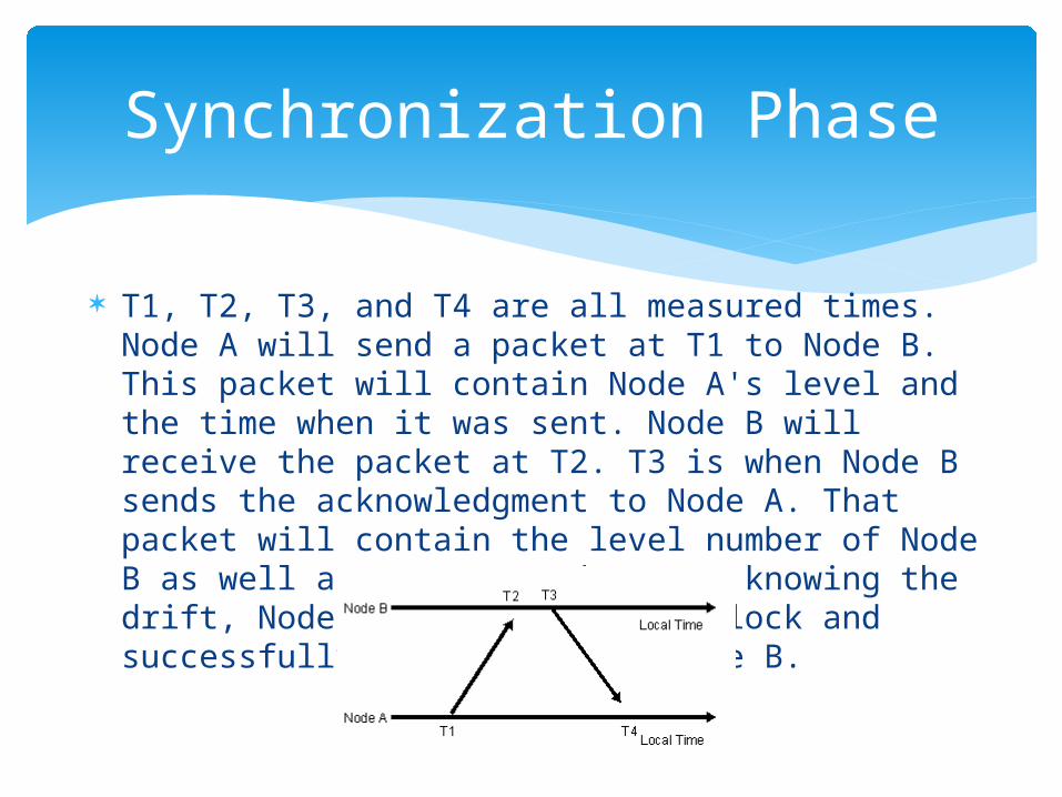
T1, T2, T3, and T4 are all measured times. Node A will send a packet at T1 to Node B. This packet will contain Node A's level and the time when it was sent. Node B will receive the packet at T2. T3 is when Node B sends the acknowledgment to Node A. That packet will contain the level number of Node B as well as T1, T2, and T3. By knowing the drift, Node A can correct its clock and successfully synchronize to Node B.
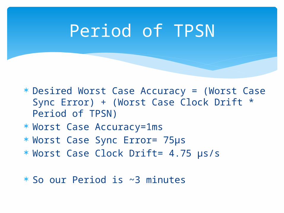
Period of TPSN
Desired Worst Case Accuracy = (Worst Case Sync Error) + (Worst Case Clock Drift * Period of TPSN)
Worst Case Accuracy=1ms Worst Case Sync Error= 75μs Worst Case Clock Drift= 4.75 μs/s So our Period is ~3 minutes
Reason for TPSN Selection
TPSN offers certain advantages over the other common wireless synchronization system (RBS)
More energy efficient (fewer messages sent) Error is (mostly) independent to the number of
nodes and typically 2x better than RBS
Node Types
Button Nodes Timer Node Start System Node Speaker Node Scoreboard Node
Primary Inputs
Hardware Inputs Rising or falling edge voltage 0-3.3V (BTR
nodes) Analog input from microphone at 8kHz into 16
bits (starter) Radio Inputs
Event packets from Xbee Radio Time sync packets from Xbee radio
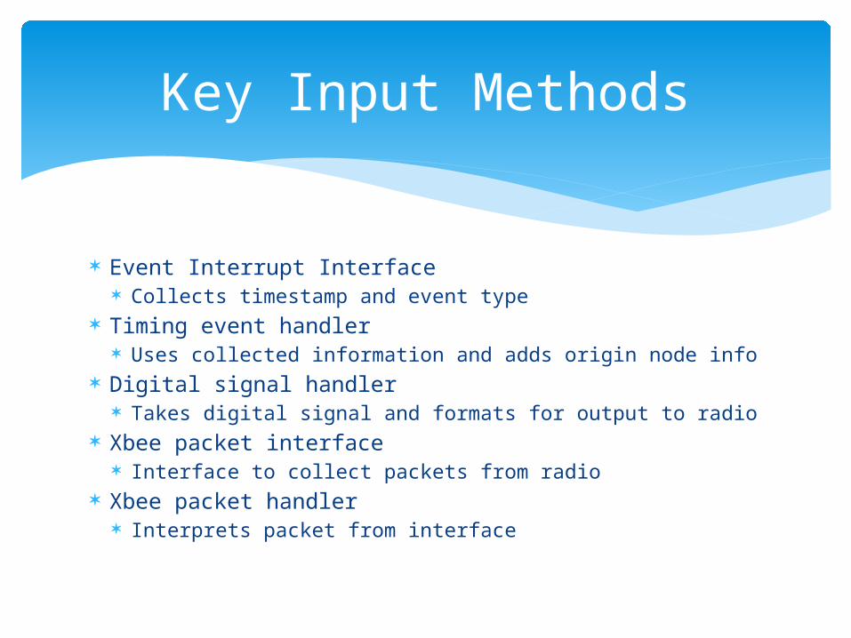
Key Input Methods
Event Interrupt Interface Collects timestamp and event type
Timing event handler Uses collected information and adds origin node info
Digital signal handler Takes digital signal and formats for output to radio
Xbee packet interface Interface to collect packets from radio
Xbee packet handler Interprets packet from interface
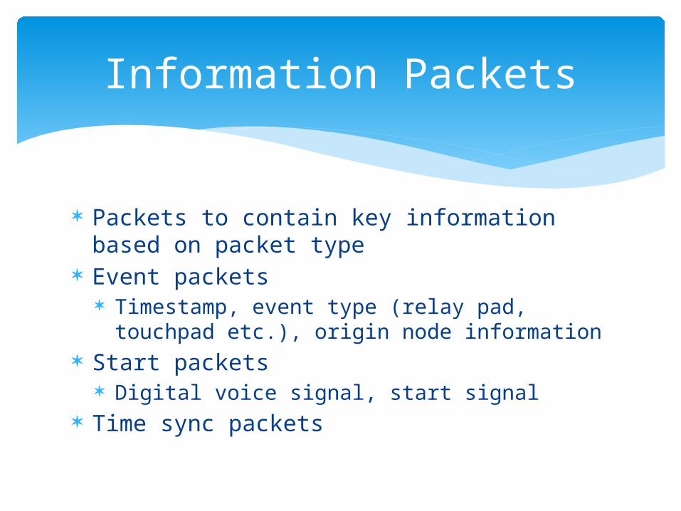
Information Packets
Packets to contain key information based on packet type
Event packets Timestamp, event type (relay pad, touchpad
etc.), origin node information Start packets
Digital voice signal, start signal Time sync packets
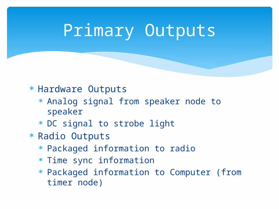
Primary Outputs
Hardware Outputs Analog signal from speaker node to speaker DC signal to strobe light
Radio Outputs Packaged information to radio Time sync information Packaged information to Computer (from timer
node)
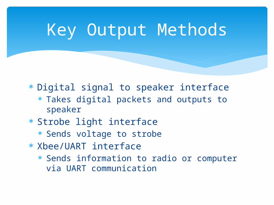
Key Output Methods
Digital signal to speaker interface Takes digital packets and outputs to speaker
Strobe light interface Sends voltage to strobe
Xbee/UART interface Sends information to radio or computer via
UART communication
Xbee Output Signal
Custom firmware settings flashed to radios Enables different settings for packet length,
baud rate etc. Enables different network setups and node
identification
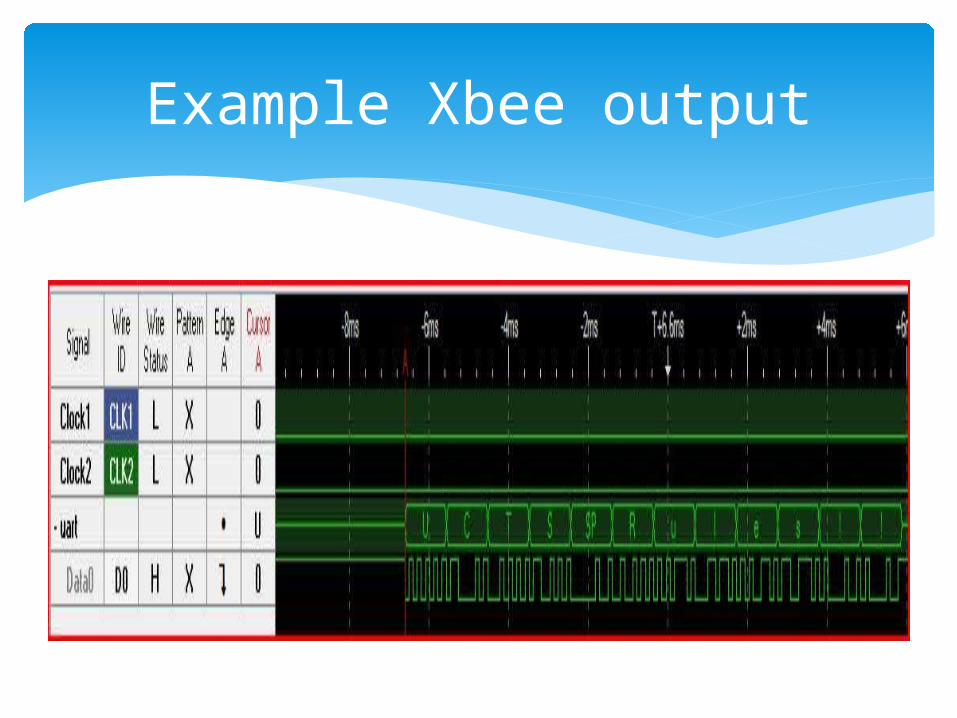
Example Xbee output
MC9S08GB60A – MCU
Suited for low power applications Has required elements
Two SCI Lines 16-bit Timers Necessary number of I/O External IRQ Pin 10 bit ADC
Well documented through App. Notes
MC9S08GB60A – Progress
Working with Development board M68DEMO908GB60E
Working Functions: 1 kHz timer interrupt (for 1 ms precision) External IRQ pin for button interrupts Serial interface to Tera Term on Computer
MC9S08GB60A – Next Step 1
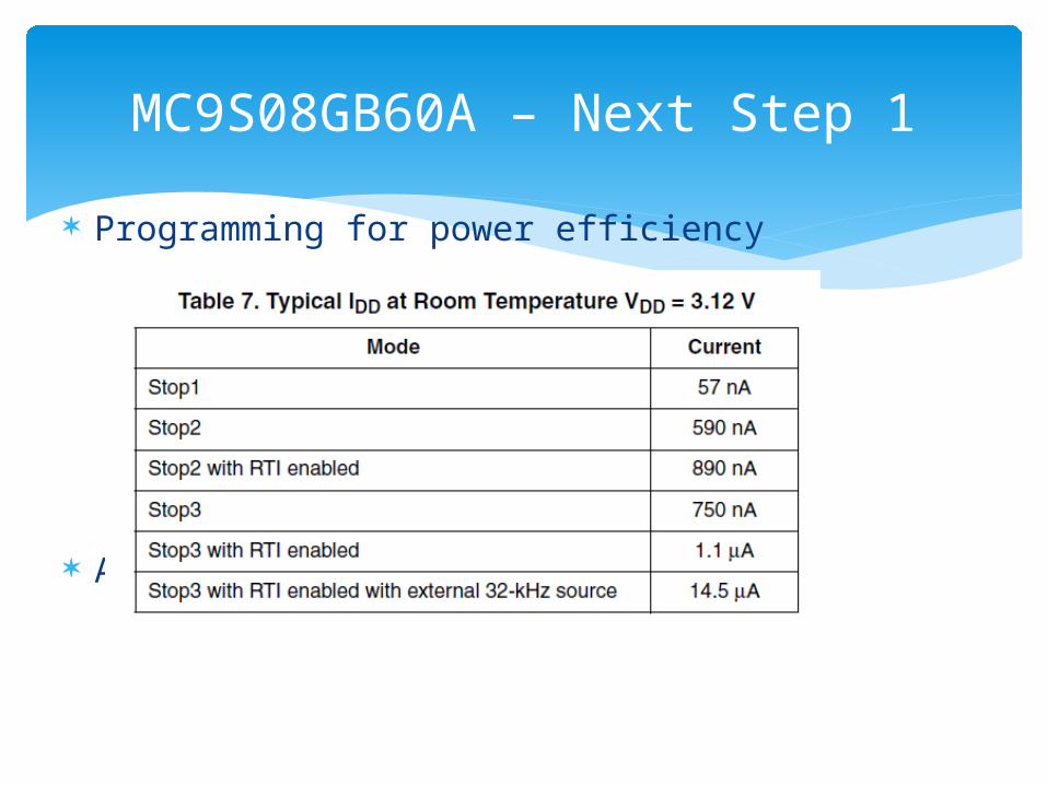
Programming for power efficiency
Also a WAIT mode
MC9S08GB60A – Next Step 2
Communication of MCU to MCU through Xbee Mesh Network Synching of two 16 bit variables Send times of when Interrupts occur between
Nodes
Testing Routines Start with 1 Lane – Race Simulation
Testing – Race Simulation
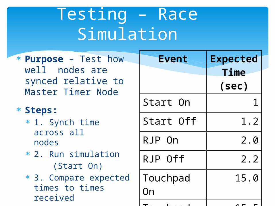
Purpose – Test how well nodes are synced relative to Master Timer Node
Steps: 1. Synch time across
all nodes 2. Run simulation
(Start On) 3. Compare expected
times to times received
Event Expected Time (sec)
Start On 1
Start Off 1.2
RJP On 2.0
RJP Off 2.2
Touchpad On 15.0
Touchpad Off 15.5
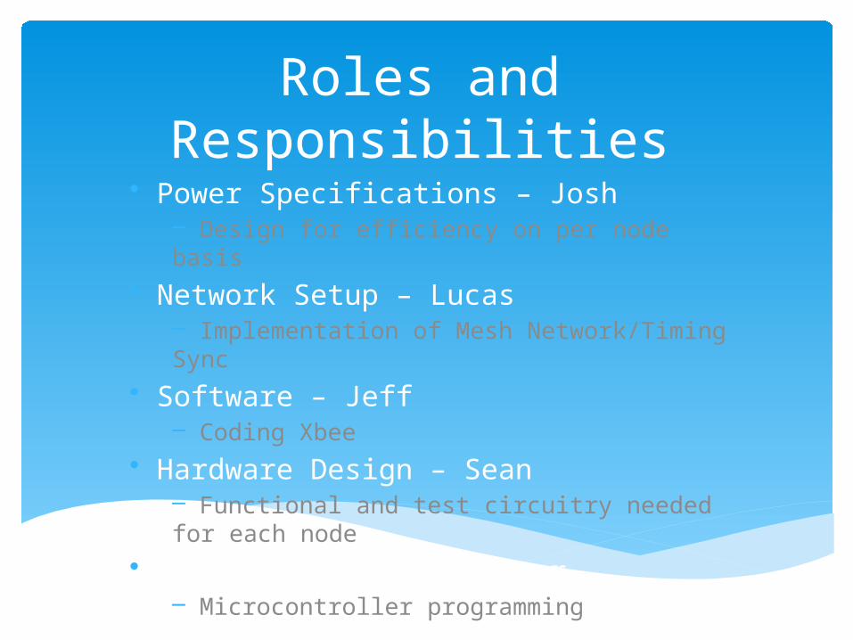
Roles and Responsibilities• Power Specifications – Josh
– Design for efficiency on per node basis• Network Setup – Lucas
– Implementation of Mesh Network/Timing Sync• Software – Jeff
– Coding Xbee• Hardware Design – Sean
– Functional and test circuitry needed for each node
• Testing Manager – Tanner– Microcontroller programming
Schedule
Plan is to continue to follow the schedule designed by Tom Brown for the year-long Capstone course
In addition, try to meet deadlines set by Colorado Time Systems
Schedule
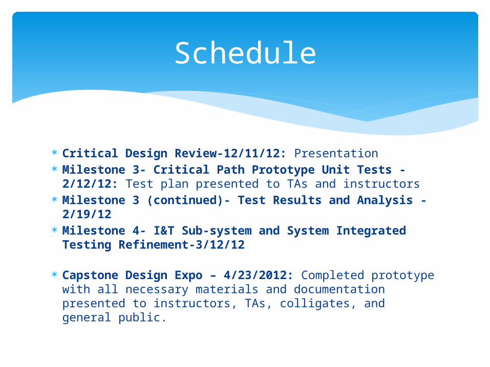
Critical Design Review-12/11/12: Presentation Milestone 3- Critical Path Prototype Unit Tests -
2/12/12: Test plan presented to TAs and instructors Milestone 3 (continued)- Test Results and Analysis -
2/19/12 Milestone 4- I&T Sub-system and System Integrated
Testing Refinement-3/12/12
Capstone Design Expo – 4/23/2012: Completed prototype with all necessary materials and documentation presented to instructors, TAs, colligates, and general public.

Questions?


