dp6 bedienung e 20120926 v1 4 - guenther- · pdf filetemperature boos t the menu item...
TRANSCRIPT

User manual control unit DP6
www.guenther-hotrunner.com 1
Deckblatt

User manual control unit DP6
2 www.guenther-hotrunner.com
© GÜNTHER Heisskanaltechnik GmbH Sachsenbergerstr. 1 D-35066 Frankenberg (Eder) Tel : +49 (0) 6451 5008 - 0 Fax: +49 (0) 6451 5008 50 E-mail [email protected] Internet www.guenther-hotrunner.com
26.09.2012 V1.4
Technical changes and errors excepted.

User manual control unit DP6
www.guenther-hotrunner.com 3
Contents 1. General notes 4
1.1 Safety information 5
2. Display and controls 6 2.1 Change operation mode 7 2.2 Temperature lowering 7 2.3 Temperature boost function 8 2.4 Loading factory defaults 9 2.5 Error messages 9
3. Parameter settings 10
3.1 Parameter menu 11 3.2 Configuration menu 13
4. Further functions 15 4.1 Softstart 15 4.2 “Ready for molding” signal 15 4.3 Start-up ramp 16 5. Connection of control circuits 17 6. Installation and start up 18 7. Table of faults and defects 19 8. Technical data 20 9. Appendix 21 9.1 Appendix A – EG declaration of conformity 21

User manual control unit DP6
4 www.guenther-hotrunner.com
1 General notes
This control unit has been build according to DIN 57411 part 1/VDE 0411 Teil1 and the regulation and standards shown in the appended EG conformity declaration and has left the factory in perfect condition. In order to maintain this standard and to guarantee safe operation, please read this user manual carefully and follow the instructions. Ensure that your local supply voltage corresponds to the unit´s nominal voltage before switching on. For safe operation, the unit must be plugged into an earthed socket. Any disconnection of the earthed conductor, e.g. by using an extension flex without earthed conductor, may cause severe danger ! Attention : Pull mains plug !
Always disconnect the unit from mains before working on electrical connectors.
This control unit contains hazardous voltage. Any repair and service work must be carried out by
qualified and authorised personell only. The components inside the unit are maintenance-free for
our customers. They are exclusively serviced by Günther Hot Runner Systems.
To operate the control unit, a fuse protected 16 A CEE socket must be used. Please note that the DP6 uses 2 phases with a maximum current of 16 A. This device is used in the commercial sector. The operator of the device is therefore subject to the legal obligations for workplace safety. In addition to the safety instructions in this manual be valid for the range of the device safety, accident prevention and environmental protection regulations are observed. All statements and information in this manual has been complied in accordance with applicable standards and regulations, the prior art as well as our many years of knowledge and experience. GÜNTHER assumes no liability for damages caused by:
� Not following the manual � Improper use � Use of untrained personnel � Unauthorized conversions and technical changes � Use of unauthorized spare parts
User manual control unit DP6
www.guenther-hotrunner.com 5
1.1 Safety information
The control unit DP6 is designed for temperature regulation of six hot runner circuits. As an application is the control of all 230 V hot runner zones provided. With an output power of up to 3500 W, very different 230 V loads can be operated via the integrated pulse control group. On the rear the illuminated main switch, the combined load and thermocouple plug and the six load fuses are positionized. The plugs contact assignment is shown in chapter 5 “Connection of control circuits”. For the protection of each circuit the six load fuses F1 – F6 are located below the load connector. Use exclusively only fuse elements type 6,3 x 32mm 16A SA (super fast acting). Attention : The maximum current for the heater circuits should not exceed 16 A. Use only original fuse type „Schurter 16A-SA 6,3x32mm“.

User manual control unit DP6
6 www.guenther-hotrunner.com
2 Display and controls
Fig. 2.1 controls of the DP6
The simple operation of the controller DP6 occurs mainly via the channel selector buttons and the „A“ and „B“ buttons. Use the channel selection buttons to first select the control circuit ( zone ) and then modify the displayed set temperature. The set temperature of the selected zone can be changed using the keys „5“ and „6“. The set temperatures of several zones can be changed after selecting them. To do this, press the zone selector keys in quick succession. A flashing parallel display indicates the selected zones. The parallel display on the right side of the controller shows the current values for all six zones. The „M“ button is used to change the displayed value to the set temperature (“SET”), the current temperature (“ACTUAL”), the deviation (“DIFF”) and the output power in %. During normal operation the actual temperatures will be shown. If there is a zone which has been turned off, the display “---” appears. On the status display a green illuminated text “OK” indicates the “ready for molding” signal if the deviation is within +/- 5°C.

User manual control unit DP6
www.guenther-hotrunner.com 7
2.1 Change operation mode
Normal operation mode for all zones is “temperature regulation”. In a case of a defective thermocouple, the mode can be changed temporarily to “percentage” with an adjustable output power in %. The setting for the unregulated output value in % should correspond to the average heating power of a similar nozzle and is set manually. By simultaneously pressing the keys “A” and “B” you can change the operation mode of the selected zone from “regulation” over “percentage” to “off”. Additionally, the mode will change if you press the zone selection key for more than 2 seconds.
Note : If the controller detects during normal operation a defective thermocouple, the heater circuit turns off and an error message appears. The DP6 controller switches over to percentage mode after confirming this message.
2.2 Temperature lowering During any long-term production pause it´s advisable to lower the temperatures. This prevents the material to get damaged. In opposite to switching off the controller, the production process can be restarted faster after the break. Pressing the lowering key activates the lowering mode. This is indicated by a green LED. The set temperatures of all zones will be reduced by a adjustable value.
Fig. 2.2 temperature lowering is activated
The activated temperature reduction is indicated by a green glowing LED and the text “red.” ( reduction ). Additionally, the lowering temperature ( f.e. 50°C ) will be shown . In order to achieve the most uniform cooling a ramp reduces the temperature within the first 2 minutes slowly. The green light of the lowering key is blinking during this cooling ramp. The temperature lowering value can be adjusted using the main menu item „red.°“. The factory default value is 50°C.

User manual control unit DP6
8 www.guenther-hotrunner.com
2.3 Temperature boost function
For starting a tool it can be helpful to raise all temperatures for a short period. After pressing the boost key the set temperatures of all zones increases to the adjustable boost value f.e. 25°C.
Fig. 2.3 activated BOOST function
The activated temperature boost is indicated by a green glowing LED and the text “boo.” ( boost ). Additionally, the boost temperature value ( f.e. 25°C ) will be shown . In order to achieve the most uniform heating a ramp increases the temperature within the first 2 minutes slowly. The green light of the boost key is blinking during this heating ramp. The temperature boost value can be adjusted using the main menu item „boo.°“. The factory default value is 25°C.
User manual control unit DP6
www.guenther-hotrunner.com 9
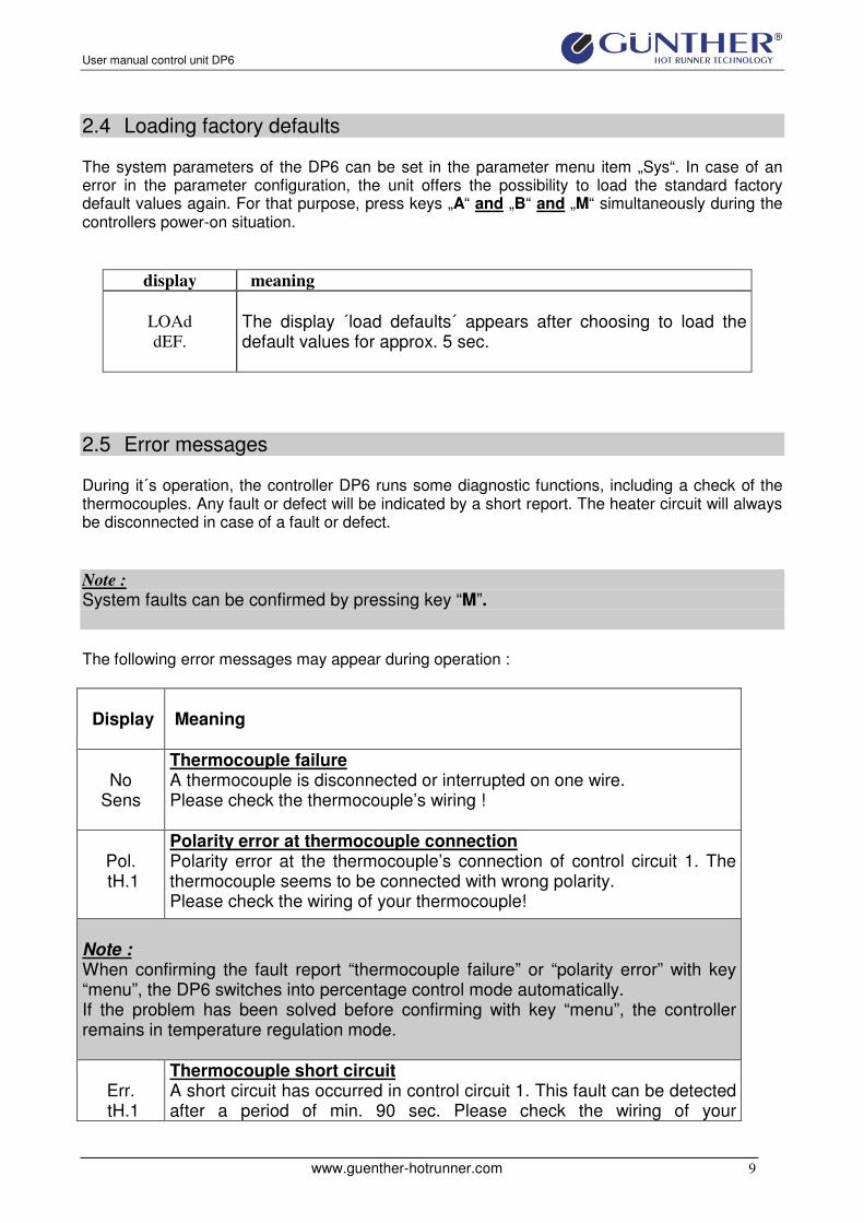
2.4 Loading factory defaults
The system parameters of the DP6 can be set in the parameter menu item „Sys“. In case of an error in the parameter configuration, the unit offers the possibility to load the standard factory default values again. For that purpose, press keys „A“ and „B“ and „M“ simultaneously during the controllers power-on situation.
display meaning
LOAd
dEF.
The display ´load defaults´ appears after choosing to load the default values for approx. 5 sec.
2.5 Error messages
During it´s operation, the controller DP6 runs some diagnostic functions, including a check of the thermocouples. Any fault or defect will be indicated by a short report. The heater circuit will always be disconnected in case of a fault or defect.
Note :
System faults can be confirmed by pressing key “M”.
The following error messages may appear during operation :
Display
Meaning
No
Sens
Thermocouple failure A thermocouple is disconnected or interrupted on one wire. Please check the thermocouple’s wiring !
Pol. tH.1
Polarity error at thermocouple connection Polarity error at the thermocouple’s connection of control circuit 1. The thermocouple seems to be connected with wrong polarity. Please check the wiring of your thermocouple!
Note : When confirming the fault report “thermocouple failure” or “polarity error” with key “menu”, the DP6 switches into percentage control mode automatically. If the problem has been solved before confirming with key “menu”, the controller remains in temperature regulation mode.
Err. tH.1
Thermocouple short circuit A short circuit has occurred in control circuit 1. This fault can be detected after a period of min. 90 sec. Please check the wiring of your

User manual control unit DP6
10 www.guenther-hotrunner.com
thermocouple !
t.Hi Ch1
Over temperature The temperature of control circuit 1 crosses the security mark. The max. allowed temperature can be set as system parameter and is set to 500°C as standard.
Err. Temp
Ambient temperature above limit The unit detected an ambient temperature of above 70°C.
3 Parameter settings
The controller’s operation depends on the setting of the parameters. For easy access, the most important parameters are displayed in a menu. The parameter menu is divided into a user menu and a configuration menu, to which the access is restricted by a password. In the user menu only non-critical system parameters can be changed. Caution :
The access to configuration data is protected by a password. The configuration should only be changed by authorised and qualified personnel. Inexpert configuration may cause damage of the hot runner system. The person who sets the unit into operation is responsible for the correct configuration of the controller.

User manual control unit DP6
www.guenther-hotrunner.com 11
3.1 Parameter menu
Fig. 3.1 flow chart for the parameter menu
You will enter the parameter menu when you press the key „M“ for more than 2 seconds. Every following key stroke on „M“ leads to the next menu item.

User manual control unit DP6
12 www.guenther-hotrunner.com
The function of each menu item will be activated using the keys „A“ or „B“. Then the display changes between “- no” or “-Yes”. Once you entered a menu item, the desired value can be changed using the “A” and “B“ keys. Parameter changes will be saved when you press the key „M“ to leave the menu item. The configuration menu is needed to change important system parameters like the PID regulation values. Note : The password for the configuration level is „0099“ on default.
Display
Meaning
qUIt
exit menu By selecting quit, the parameter menu will be closed. Press key „A“ or „B“ to return to the normal operating level. If for approximately 10 seconds no key has been pressed, the parameter menu closes automatically.
SoFt
softstart The softstart function for 230V nozzles is selected by entering the menu SOFT. Here you can enable or disable the softstart function.
rEd° rEdA
temperature lowering The menu item ‚set value lowering‘ („rEd.°“ or „rEd.A“) enables the user to set the lowering temperature or the lowering current.
bOO°
temperature boost The menu item ‚set value boost‘ („bOO.°“) is used to adjust the boost temperature.
ConF
configuration menu The menu item ´configuration menu´ („CONF.“) enables the user to enter the configuration menu. This menu is protected by a password. Please refer to chapter 3.2 “Configuration menu”.

User manual control unit DP6
www.guenther-hotrunner.com 13
3.2 Configuration menu
Fig. 3.1 flow chart of the configuration menu
The system parameters of controller DP6 can be set in the configuration menu. After entering the password ( “0099” ), the various items for frequently used parameters can be changed easily. The item ‚system‘ allows changes to all parameters. Therefore it is protected by an additional password. Changes of system parameters must be carried out by authorised and qualified personnel.

User manual control unit DP6
14 www.guenther-hotrunner.com
Display
Meaning
ConF - - - -
configuration menu The configuration menu is used to change the controllers parameters. You have to enter the correct password before entering this menu area. Consider that the digits of the password have to be entered starting right by pressing key “A” or “B”. Each of the four digits must be entered by pressing the key “M”. The standard password is “0099”.
Pid1..6
PID parameters The item PID1..6 allows to change the PID regulation parameters for each zone manually.
UnIt temperature unit This menu item is used to choose the temperature unit °C or °F.
Hour counter operating time The operating hours will be shown in this menu item.
SYS
system parameters After entering the menu item ‚sys‘, the system parameters of the DP6 can be changed. The menu is protected by a password and enables the user to set and change all system parameters. Changes to the system parameters should only be carried out by authorised and qualified personnel. If the manual configuration of the system parameters is inadequate or faulty, it is possible to load the standard default values as described in chapter 2.4 “Loading default values”.
qUIt
exit menu By selecting quit, the parameter menu is closed. To return to the normal operating level, press key “A” or “B”. If for approx. 10 seconds no key has been pressed, the parameter menu will be quit automatically.

User manual control unit DP6
www.guenther-hotrunner.com 15
4 Further functions
4.1 Softstart
The first heating of a hot runner system should be done as gently as possible. When using 230V heaters, a softstart is necessary in order to remove the moisture slowly from the heaters. Therefore the output power increases in a so-called ramp time from 0 to 40 % during the first phase of the softstart. The ramp time should guarantee that a temperature of 105°C is reached at its end. During the following hold time the DP6 regulates the temperature to 105° independent to the selected set values. During the hold time, the nozzles are dried out adequately with a low thermical load. This start-up procedure occurs automatically, when switching the controller on. After the hold time the unit switches into normal operating condition. The typical running time is 10 minutes.
Note : The softstart function can be de-activated in the parameter menu. It will be reactivated again every time you power-up the controller
4.2 „Ready for molding“ signal
At the end of the heating phase all zones reaches the temperature window of +/- 5 °C and are then in a steady state. The complete hot runner readiness is achieved when all zones are adjusted for a certain time periode. The DP6 activates the “ready for molding” relay after an adjustable delay time. Especially for needle valve systems a “ready for molding” delay of f.e. 120 sec is recommended. You can change the delay time for the “OK” signal using the parameter 57 in the system parameter menu. The „OK“ relay contact ( connector Wieland ST17/2BA ) on the controllers rear will turn on if the “ready for molding” signal is active. This potential-free relay contact (250 V / 5 A ) can be connected with the molding machine to stop the cycle automatically in a case of unsuitable temperatures.

User manual control unit DP6
16 www.guenther-hotrunner.com
4.3 Start-up ramp
A typical hot runner system contains some fast acting nozzles and single slow acting manifold plates. To prevent material damages it´s recommended to heat up all zones uniform to the slowest one. The automatic start-up ramp detects the slowest heater circuit ( manifold ) and tries to heat up this circuit as fast as possible. All other zones will heat up only as fast as the detected manifold zone. As a result, all zones achieves their operating temperatures at one time.
Fig. 4.1 start-up ramp detects the manifold on zone 1
During the start-up ramp the text „RP“ and the zone number of the detected manifold circuit will be displayed. If the automatic manifold detection doesn´t find the correct zone, you can set the manifold zone also manually. Therefore the parameter 42 is helpful.
Value of parameter 42
Function
0 Start-up ramp deactivated
1 - 6 manual manifold presetting ( zone number 1 – 6 )
9 automatic manifold detection
( default )

User manual control unit DP6
www.guenther-hotrunner.com 17
5 Connection of control circuits
Fig. 5.1 connector on the DP6 rear
On the controllers rear you will find the 24-pin HAN24 connector for the heater circuits and the thermocouples. Each 230 V load circuit and it´s thermocouple will be connected using these solid 20A contacts. Please refer to fig. 5.2 for informations about the assignment for heaters and thermocouples.
Fig. 5.2 Assignment load and thermocouple connection
zone 1 2 3 4 5 6
load 1 (phase) 1 3 5 7 9 11
load 2 (neutral) 2 4 6 8 10 12
Thermocouple + 13 15 17 19 21 23
Thermocouple - 14 16 18 20 22 24

User manual control unit DP6
18 www.guenther-hotrunner.com
6 Installation and start up
Fig. 6.1 rear of the DP6 controller
Ensure that the controller DP6 has a stable position where no heat can occur. The electrical connection will be done using the 5-pin CEE plug in 16 A version. The used CEE socket must be fused with a 16 A circuit breaker. It´s not allowed to operate the controller on a 32 A CEE socket.
Installation :
• Plug in the 24-pin load connector with the connected regulation zones • Plug in 16A CEE mains plug for power supply
• Turn on the main switch
• Set the desired set temperatures for all zones
• During initial start-up you should activate each zone one after the other. So you can
find possible mix-up of thermocouples or heater loads.
• After switching on the control unit, please wait for a few minutes until all zones are heated up evenly

User manual control unit DP6
www.guenther-hotrunner.com 19
7 Table of faults and defects
During operation, the DP6 checks continuously the regulation circuits on faults or defects . A corresponding error message will be shown, if an error appears.
Message
Fault / Defect
Possible cause
Countermeasure
A Fault report ”no sensor 3”
Thermocouple of zone 3 defect
Thermocouple is not connected or interrupted
Check connection plug and cable of thermocouple
B Fault report ”Pol. TH 1”
Polarity error at thermocouple of zone 1
Polarity error at the thermocouple
Correct the polarity
C Fault report ”no load 2”
100 % output power but no temperature increasement on zone 2
defective fuse or disconnected heater or short circuit on the thermocouple
Check the 16A fuse of zone 2 or check the thermocouple
D Significant fluctuation of temperature (+/- 100 °C )
Thermocouple defect or load circuit not earthed
Check the earth wire of the load circuit
E Temperature doesn´t increase
load circuits swapped
Check assignment of heater circuit to the thermocouple
Note : The earth wire of all tool elements like heaters and thermocouples must be in a good condition. Lack of earthing or insufficiently earthed heating elements may cause severe errors in temperature reading. Note : During initial start-up the zone’s assignment must be checked. For that purpose the user should heat up the control circuits one by one and monitor the temperature rise.

User manual control unit DP6
20 www.guenther-hotrunner.com
8 Technical data
Nominal Voltage: 2-phasig, 2 x 230VAC ( +5 / -10% ) ( L1, L2 , N, PE ) Mains plug : CEE-16A Stecker, 5-polig ( 2 Phasen belegt ), Länge 3 m Nominal capacity : 7000 W, 2 x 16A
Standby capacity : ca. 10 VA Load connection: 6 x heater circuit 230V / 16A, ( zones 1-6 ) Harting series HAN24 ( contacts 1-12 )
Temperature sensor: 6 x thermocouple Typ L ( FeCu-Ni ), Harting series HAN24 ( contacts 13-24 ) Fuses: 16A FF Schurter Typ SA super fast acting for triacs ( zone 1 – 6 )
Regulation: Fuzzy-PID regulator with puls group control, 0 bis 500°C ( 0...932° F)
Storage temperature: -25 bis 80°C
Operating temperature: 0 bis 45°C
Protection type : IP 20
Dimensions: (B, H, T) 259mm x 95mm x 290mm
Colour: grau und blau (RAL 9018 und RAL 5015)
Weight: 3,8 kg

User manual control unit DP6
www.guenther-hotrunner.com 21
9 Appendix
9.1 Appendix A – EG-Konformitätserklärung
For the following below listed products:
Günther Hot Runner Controller DP6 We hereby confirm that above listed products comply to all important safety requirements that have been declared by the Council of Assimilation of legal regulations by the EC membership countries concerning electromagnetical conformity. 89/336/EEC EMC electromagnetic compatibility 73/23/EEC Low voltage requirements To verify these products to electromagnetical conformity the following standards were referred to: EN 50081, part 2 EN 50082, part 2 The above mentioned products also comply to: DIN EN 61010, Teil 1/03.94. DAVIDSMEYER & PAUL GmbH Elektronik Brüsselerallee 12 D-41812 Erkelenz Erkelenz, den 01.06.2012 J. Marquardt (Geschäftsführer)