dr. augustine ofori agyeman assistant professor of chemistry department of natural sciences clayton...
TRANSCRIPT

DR. AUGUSTINE OFORI AGYEMANAssistant professor of chemistryDepartment of natural sciences
Clayton state university
INSTRUMENTAL ANALYSIS CHEM 4811
CHAPTER 15

CHAPTER 15
ELECTROANALYTICAL CHEMISTRY
- The study of the relations between chemical reactions and electricity
- The study of the interconversion of chemical energy and electrical energy
- The study of redox reactions
- Electrochemical processes involve the transfer of electrons from one substance to another
ELECTROCHEMISTRY

Electroactive Species
- Species that undergoes an oxidation or a reduction during reaction
- Species may be complexed, solvated, molecule, or ion
- Species may be in aqueous or nonaqueous solution
ELECTROCHEMISTRY

- The use of electrochemical techniques to characterize a sample
- Deals with the relationship between electricity and chemistry
- Analytical calculations are based on the measurement of electrical quantities (current, potential, charge, or resistance)
and their relationship to chemical parameters
ELECTROANALYTICAL CHEMISTRY

Advantages
- Measurements are easy to automate as they are electrical signals
- Low concentrations of analytes are determined without difficulty
- Far less expensive equipment than spectroscopy instruments
ELECTROANALYTICAL CHEMISTRY

FUNDAMENTAL CONCENPTS
Redox Reaction
- Oxidation-reduction reaction
- Reactions in which electrons are transferred from one substance to another
Oxidation- Loss of electrons
Reduction- Gain of electrons
Oxidized Species
- The species that loses electrons
- The reducing agent (reductant)
- Causes reduction
Fe(s) ↔ Fe2+(aq) + 2e-
FUNDAMENTAL CONCENPTS

Reduced Species
- The species that gains electrons
- Oxidizing agent (oxidant)
- Causes oxidation
Cu2+(aq) + 2e- ↔ Cu(s)
FUNDAMENTAL CONCENPTS

Half Reactions
- Just the oxidation or the reduction is given
- The transferred electrons are shown
Oxidation Half-Reaction
- Electrons are on the product side of the equation
Reduction Half-Reaction
- Electrons are on the reactant side of the equation
FUNDAMENTAL CONCENPTS
Half Reactions
Oxidation half reactionFe(s) ↔ Fe2+(aq) + 2e-
Fe2+ ↔ Fe3+ + e-
Reduction half reaction Cu2+(aq) + 2e- ↔ Cu(s)
Cl2(g) + 2e- ↔ 2Cl-
FUNDAMENTAL CONCENPTS

- Many redox reactions are reversible
- Reduction reaction becomes oxidation reaction when it is reversed and vice versa
- Sum of oxidation and reduction half-reactions gives the net redox reaction or the overall reaction
- No electrons appear in the overall reaction
FUNDAMENTAL CONCENPTS

The Overall Reaction- Both an oxidation and a reduction must occur in a redox reaction
- The oxidizing agent accepts electrons from the reducing agent
Cu2+(aq) + Fe(s) ↔ Cu(s) + Fe2+(aq)
- Oxidizing agent- Reduced species
- Electron gain
- Reducing agent- Oxidized species
- Electron loss
FUNDAMENTAL CONCENPTS

Charge (q)
Charge (q) of an electron = - 1.602 x 10⁻¹⁹ CCharge (q) of a proton = + 1.602 x 10⁻¹⁹ C
C = coulombs
Charge of one mole of electrons = (1.602 x 10⁻¹⁹ C)(6.022 x 10²³/mol) = 96,485 C/mol
= Faraday constant (F)
- The charge (q) transferred in a redox reaction is given by q = n x F
FUNDAMENTAL CONCENPTS
Current (i)
- The quantity of charge flowing past a point in an electric circuit per second
i = q/time
Units Ampere (A) = coulomb per second (C/s)
1A = 1C/s
FUNDAMENTAL CONCENPTS

Voltage or Potential Difference (E)
- The amount of energy required to move charged electrons between two points
- Work done by or on electrons when they move from one point to another
w = E x q or E = w/q
Units: volts (V or J/C)
1V = 1J/C
FUNDAMENTAL CONCENPTS

Ohm’s Law
i = E/R
R = resistance
UnitsΩ (ohm) or V/A
FUNDAMENTAL CONCENPTS

Electrode
- Conducts electrons into or out of a redox reaction system
- The electrode surface serves as a junction between an ionic conductor and an electronic conductor
Examplesplatinum wire
carbon (glassy or graphite) GoldSilver
FUNDAMENTAL CONCENPTS

Electroactive Species- Donate or accept electrons at an electrode
- Can be made to oxidize or reduce
Electrochemical Measurements- Occur at the electrode – solution interface
Chemical Measurements- Involve homogeneous bulk solutions
FUNDAMENTAL CONCENPTS
- Made up of the electrodes and the contacting sample solution
- Electrical conductor is immersed in a solution of its own ions
- A potential difference (voltage) is created between the conductor and the solution
- The system is a half-cell
- The metal conductor is an electrode and the solution is an electrolyte
ELECTROCHEMICAL CELL

Electrode Potential
- A measure of the ability of the half-cell to do work(the driving cell for the half-cell reaction)
Anode- Electrode where oxidation occurs
Mo → Mn+ + ne-
- Metal loses electrons and dissolves (enters solution)Cd(s) → Cd2+ + 2e-
Ag(s) → Ag+ + e-
ELECTROCHEMICAL CELL

Cathode
- Electrode where reduction occursMn+ + ne- → Mo
- Positively charged metal ion gains electrons
- Neutral atoms are deposited on the electrode
- The process is called electrodeposition
Cd2+ + 2e- → Cd(s)Ag+ + e- → Ag(s)
ELECTROCHEMICAL CELL

ELECTROLYSIS
- Voltage is applied to drive a redox reaction thatwould not otherwise occur
Examples- Production of aluminum metal from Al3+
- Production of Cl2 from Cl-

ELECTROLYTIC CELL
- Nonspontaneous reaction
- Requires electrical energy to occur
- Consumes electricity from an external source

- Spontaneous reaction
- Produces electrical energy
- Can be reversed electrolytically for reversible cells
ExampleRechargeable batteries
Conditions for Non-reversibility- If one or more of the species decomposes
- If a gas is produced and escapes
GALVANIC CELL

- Also known as voltaic cell
- A spontaneous redox reaction generates electricity
- One reagent is oxidized and the other is reduced
- The two reagents must be separated (cannot be in contact)
- Electrons flow through a wire (external circuit)
GALVANIC CELL

Oxidation Half-Reaction- Loss of electrons
- Occurs at anode (negative electrode)- The left half-cell by convention
Reduction Half-Reaction- Gain of electrons
- Occurs at cathode (positive electrode)- The right half-cell by convention
GALVANIC CELL

GALVANIC CELL
Salt Bridge
- Connects the two half-cells (anode and cathode)
- Filled with gel containing saturated aqueous salt solution (KCl)
- Ions migrate through to maintain electroneutrality (charge balance)
- Prevents charge buildup that may cease the reaction process
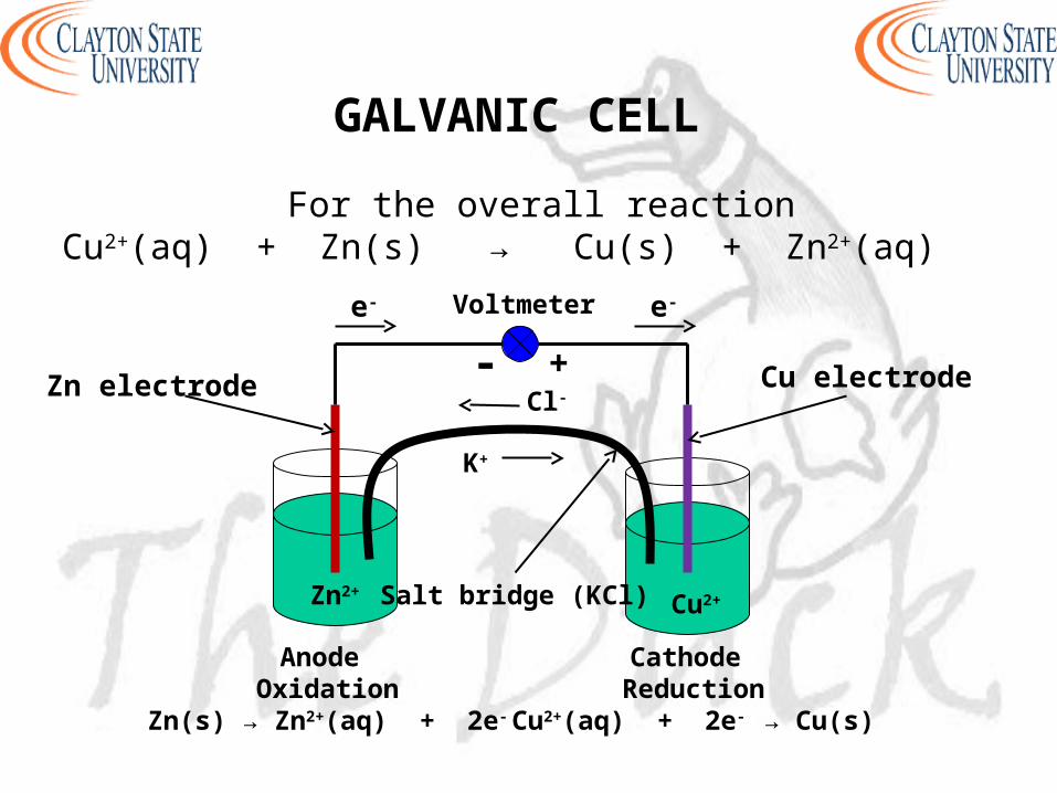
For the overall reactionCu2+(aq) + Zn(s) → Cu(s) + Zn2+(aq)
Anode Oxidation
Zn(s) → Zn2+(aq) + 2e-
Cathode Reduction
Cu2+(aq) + 2e- → Cu(s)
Salt bridge (KCl)
Cl-
K+
Voltmeter
- +
e- e-
Cu electrodeZn electrode
Cu2+Zn2+
GALVANIC CELL

Line Notation
Phase boundary: represented by one vertical line
Salt bridge: represented by two vertical lines
Fe(s) FeCl2(aq) CuSO4(aq) Cu(s)
GALVANIC CELL

STANDARD POTENTIALS
Standard Reduction Potential (Eo)
- Used to predict the voltage when different cells are connected- Potential of a cell as cathode compared to
standard hydrogen electrode- Species are solids or liquids
- Activities = 1
- We will use concentrations for simplicityConcentrations = 1 M
Pressures = 1 bar
STANDARD POTENTIALS
Standard Hydrogen Electrode (SHE)
- Reference electrode half-cell
- Used to measure Eo for half-reactions (half-cells)
- Connected to negative terminal (anode)
Assigned Eo = 0.000 under standard state conditions(T = 25 oC, concentration = 1M, pressure = 1 bar,
pure solid or liquid)

STANDARD POTENTIALS
Standard Hydrogen Electrode (SHE)
Consists of - Platinized Pt electrode immersed in a solution of 1M HCl
- H2 gas (1 bar) is bubbled over the Pt electrode
2H+(aq, 1 M) + 2e- ↔ 2H2 (g, 1 bar)

CELL POTENTIALS
- The potential for a cell containing a specified concentrationof reagent other than 1 M
Standard Cell PotentialEo
cell = Eocathode – Eo
anode
Cell PotentialEcell = Ecathode – Eanode
- Ecell is positive for spontaneous reactions
- Half-reaction is more favorable for more positive Eo
CELL POTENTIALS
Junction Potential
- Is produced when there is a difference in concentrationor types of ions of the two half-cells
- Is created at the junction of the salt bridge and the solution
- Is a source of error
- Minimized in KCl salt bridge due to similar mobilities of K+ and Cl-

Half ReactionF2 + 2e- ↔ 2F-
MnO4- + 5e- ↔ Mn2+
Ce4+ + e- ↔ Ce3+ (in HCl)O2 + 4H+ + 4e- ↔ 2H2O
Ag+ + e- ↔ Ag(s)Cu2+ + 2e- ↔ Cu(s)2H+ + 2e- ↔ H2(g)Cd2+ + 2e- ↔ Cd(s)Fe2+ + 2e- ↔ Fe(s)Zn2+ + 2e- ↔ Zn(s)Al3+ + 3e- ↔ Al(s)
K+ + e- ↔ K(s)Li+ + e- ↔ Li(s)
Eo (V)2.8901.5071.2801.2290.7990.3390.000-0.402-0.440-0.763-1.659-2.936-3.040In
crea
sing
oxi
dizi
ng p
ower
Incr
easi
ng r
educ
ing
pow
er
Oxidizingagents
Reducingagents
CELL POTENTIALS

- Elements that are more powerful reducing agents than hydrogen show negative potentials
- Elements that are less powerful reducing agents than hydrogen show positive potentials
- Metals with more negative Eo are more active
- More active metals displace less active metals from solution
Fe will displace Cu2+ out of solutionZn dissolves in HCl but Cu does not
CELL POTENTIALS

NERNST EQUATION
Gives relationship between the potential of an electrochemical cell and the concentration of reactants and products
O + ne- ↔ R
R
Olog
nF
2.3RTEE O
E = electrode potentialEo = standard potential for the redox reaction
R = gas constant = 8.314 J/K-molT = absolute temperature in Kelvin
F = Faraday’s constant = 96,485 C/moln = number of electrons transferred

NERNST EQUATION
a
bO
A
Blog
n
0.05916EE
For the half reaction
aA + ne- ↔ bB
The half-cell potential (at 25 oC), E, is given by
a
bO
A
Bln
nF
RTEE
a
bO
A
Blog
nF
2.3RTEE

NERNST EQUATION
For the overall reaction
aA + bB ↔ cC + dD
The potential at 25 oC is given by
ba
dcO
BA
DClog
nF
2.3RTEE
ba
dcO
BA
DCln
nF
RTEE
ba
dcO
BA
DClog
n
0.05916EE

NERNST EQUATION
- E = Eo when [O] = [R] = 1M
- Concentration for gases are expressed as pressures in bars or atm
- Concentrations for pure solids, liquids, and solvents are omitted (activity = 1)
- Reduction is more favorable on the negative side of Eo
- When a half reaction is multiplied by a factorEo remains the same

REFERENCE ELECTRODES
- An ideal reference electrode
- Has a fixed potential over time and temperature
- Long term stability
- Ability to return to the initial potential after exposure to small currents (reversible)
- Obey the Nernst equation

REFERENCE ELECTRODES
Standard Hydrogen Electrode (SHE)E = 0.000 V
Saturated Calomel Electrode (SCE)- Composed of metallic mercury in contact with saturated
solution of mercurous chloride (calomel, Hg2Cl2)
- Pt wire is in contact with the metallic mercury
- Calomel is in contact with saturated KCl solution
E = +0.244 V at 25 oC

REFERENCE ELECTRODES
Silver/Silver Chloride Reference Electrode (Ag/AgCl)
- Consists of silver metal coated with silver chloride paste
- Immersed in saturated KCl and AgCl solution
E = +0.199 V at 25 oC

ELECTROANALYTICAL METHODS
Two main types - Potentiometric and Potentiostatic
- The type of technique reflects the type of electrical signal used for quantitation
- Techniques require at least two electrodes and an electrolyte (containing solution)
ElectrodesWorking (indicator) electrode, reference electrode, counter electrode

Potentiometric Technique
- Based on a static (zero-current) situations
- Based on measurement of the potential established across a membrane
- Used for direct monitoring of ionic species (Ca2+, Cl-, K+, H+)
ELECTROANALYTICAL METHODS

Potentiostatic Technique
- Controlled-potential technique
- Based on dynamic (non-zero-current) situations
- Deals with the study of charge transfer processes at the electrode-solution interface
- Chemical species are forced to gain or lose electrons
ELECTROANALYTICAL METHODS

- Potentiometry
- Coulometry
- Voltammetry
- Polarography
- Methods are classified according to the variable being measured
- One variable (current, voltage, charge) is measured and the others are controlled
ELECTROANALYTICAL METHODS

- Based on static (zero-current) measurements
- Involves measurement of potential (voltage) of an electrochemical cell
- Used to obtain information on the composition of an analyte
- Potential between two electrodes is measured (indicator electrode and reference electrode)
- Indicator (sensing) electrode responds to the concentration of the analyte species
POTENTIOMETRY

- The analyte concentration is related to the potential difference between the indicator electrode and the reference electrode
(by applying the Nernst equation)
- Indicator electrode is connected to a reference electrode (SCE, Ag/AgCl) to form a complete cell
- Implies Etotal = Eindicator – Ereference
- Reference electrode is connected to the negative terminal of the readout device (potentiometer)
POTENTIOMETRY

Applications
- Environmental monitoring
- Clinical diagnostics (blood testing, electrolytes in blood)
- Control of reaction processes
POTENTIOMETRY

- Electrode that responds to change in analyte activity
- Generally show high degree of selectivity
Types of indicator electrodes- Metallic electrodes (metal wire, mesh, or strip)
- Metal coated with its sparingly soluble salt (Ag/AgCl)- Electrode whose equilibrium reaction responds to nalyte cation
- Redox indicator electrode (measures redox reactions)
INDICATOR ELECTRODE

- Are indicator electrodes
- Respond directly to the analyte
- Used for direct potentiometric measurements
- Selectively binds and measures the activity of one ion (no redox chemistry)
ExamplespH electrode
Calcium (Ca2+) electrodeChloride (Cl-) electrode
ION-SELECTIVE ELECTRODES (ISE)
Advanteages
- Exhibit wide response
- Exhibit wide linear range
- Low cost
- Color or turbidity of analyte does not affect results
- Come in different shapes and sizes
ION-SELECTIVE ELECTRODES (ISE)

- Made from a permselective ion-conducting membrane(ion-exchange material that allows ions of one electrical
sign to pass through)
- Reference electrode is inbuilt
- Internal solution (solution inside electrode) contains ion of interest with constant activity
- Ion of interest is also mixed with membrane
- Membrane is nonporous and water insoluble
ION-SELECTIVE ELECTRODES (ISE)
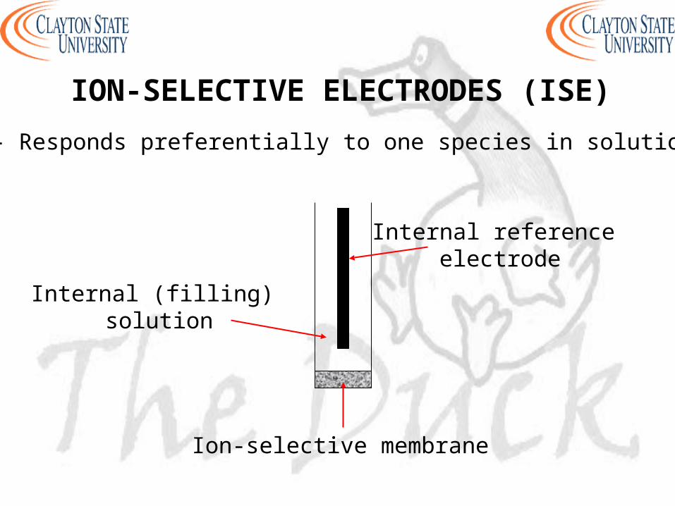
- Responds preferentially to one species in solution
Internal reference electrode
Ion-selective membrane
Internal (filling) solution
ION-SELECTIVE ELECTRODES (ISE)

- If C+ is the preferential ion
- [C+] inside the electrode ≠ [C+] outside the electrode
- Results in a potential difference across the membrane
Generally (at 25 oC)- 10-fold change in activity implies 59/zi mV change in E- zi is the charge on the selective ion (negative for anions)
- zi = +1 for K+, zi = +2 for Ca2+, zi = -2 for CO32-
ION-SELECTIVE ELECTRODES (ISE)
inner
outer
i ][C
][Cln
Fz
RTE
inner
outer
i
o
][C
][Clog
z
0.05916EC, 25At

- Let ci = molarity of C+
- Activity (ai) rather than molarity is measured by ISEs
- Activity is the effective (active) concentration of analyte(effective concentration decreases due to ionic interactions)
ai = γici
where γi = activity coefficient (between 0 and 1)
ION-SELECTIVE ELECTRODES (ISE)

Selectivity Coefficient (k)
- A measure of the ability of ISE to discriminate against an interfering ion
- It is assumed that ISEs respond only to ion of interest
- In practice, no electrode responds to only one specific ion
- The lower the value of k the more selective is the electrode
- k = 0 for an ideal electrode (implies no interference)
ION-SELECTIVE ELECTRODES (ISE)

Selectivity Coefficient (k)
For k > 1- ISE responds better to the interfering ion than to the target ion
For k = 1- ISE responds similarly to both ions
For k < 1- ISE responds more selectively to ion of interest
ION-SELECTIVE ELECTRODES (ISE)

Empirical Calibration PlotP
oten
tial
(m
V)
p[C+]
Slope = 59/zi mV
zi = charge of ion
Called Nernstian slope
- Used to determine the unknown concentration of analytes
- Departure from linearity is observed at low concentrations
ION-SELECTIVE ELECTRODES (ISE)
Three groups of ISEs
- Glass electrodes
- Liquid electrodes
- Solid electrodes
ION-SELECTIVE ELECTRODES (ISE)

GLASS ELECTRODES
- Responsive to univalent cations
- Employs thin ion-selective glass membrane

pH GLASS ELECTRODE
- The most widely used
- For pH measurements (selective ion is H+)
- Response is fast, stable, and has broad range
- pH changes by 1 when [H+] changes by a factor of 10
- Potential difference is 0.05196 V when [H+] changes by a factor of 10
For a change in pH from 3.00 to 6.00 (3.00 units)Potential difference = 3.00 x 0.05196 V = 0.177

pH GLASS ELECTRODE
- Thin glass membrane (bulb) consists of SiO4
- Most common composition is SiO2, Na2O, and CaO
Glass membrane contains - dilute HCl solution saturated in AgCl
- inbuilt reference electrode (Ag wire coated with AgCl)

pH GLASS ELECTRODE
Glass Electrode Response at 25 oC (potential across membrane with respect to H+)
ΔpH = pH difference between inside and outside of glass bulb
β ≈ 1 (typically ~ 0.98)(measured by calibrating electrode in solutions of known pH)
K = assymetry potential (system constant, varies with electrodes)
ΔpHβ(0.05916)KE
)log(a 0.05916 -KEH
pH GLASS ELECTRODE
- Equilibrium establishes across the glass membrane with respect to H+ in inner and outer solutions
- This produces the potential, E
- Linearity between pH and potential
- Calibration plot yields slope = 59 mV/pH units
- Electrode is prevented from drying out by storing in aqueous solution when not in use

pH GLASS ELECTRODE
Sources of Error
- Standards used for calibration- Junction potential- Equilibration time
- Alkaline (sodium error)- Temperature- Strong acids
- Response to H+ (hydration effect)

OTHEER GLASS ELECTRODES
Glass Electrodes For Other CationsK+ -, NH4
+-, Na+-selective electrodes- Mechanism is complex
- Employs aluminosilicate glasses (Na2O, Al2O3, SiO2)- Minimizes interference from H+ when solution pH > 5
pH Nonglass Electrodes- Quinhydrone electrode (quinone – hydroquinone couple)
- Antimony electrode

SOLID-STATE ELECTRODES
- Solid membranes that are selective primarily to anions
Solid-state membrane may be - single crystals (most common)
- polycrystalline pellets or
- mixed crystals

SOLID-STATE ELECTRODES
- Ionic solid contains the target ion
- Solid is sealed to the end of a polymer tube
- Contains internal reference electrode and filling solution
- Concentration difference across the membrane causes migration of charged species across the membrane
- Can measure concentrations as low as 10-6 M
SOLID-STATE ELECTRODES
Examples
- Most common is fluoride-ion-selective electrode (limited pH range of 0-8.5)
(OH- is the only interfering ion due to similar size and charge)
- Iodide electrode (high selectivity over Br- and Cl-)
Chloride electrode (suffers interference from Br- and I-)
Thiocynate (SCN-) and cyanide (CN-) electrodes

LIQUID MEMBRANE ELECTRODES
- Employs water-immiscible substances impregnated in a polymeric membrane (PVC)
- For direct measurement of polyvalent cations and some anions
- The inner solution is a saturated solution of the target ion
- Hydrophilic complexing agents (e.g. EDTA) are added to inner solutions to improve detection limits
- Inner wire is Ag/AgCl

Ion-Exchange Electrodes
- The basis is the ability of phosphate ions to form stable complexes with calcium ions
- Selective towards calcium
- Employs cation-exchanger that has high affinity for calcium ions(diester of phosphoric acid)
- Inner solution is a saturated solution of calcium chloride
)log(a2
0.05916KE Ca
LIQUID MEMBRANE ELECTRODES
- Cell potential is given by

Other Ion-Exchange Electrodes
- Have poor selectivity and are limited to pharmaceutical formulations
Examples- IEE for polycationic species (polyarginine, protamine)
- IEE for polyanionic species (DNA)- IEE for detection of commonly abused drugs
(large organic species)
LIQUID MEMBRANE ELECTRODES

Anion-Selective Electrodes
- For sensing organic and inorganic anions
Examples of Anions- Phosphate- Salicylate
- Thiocyanate- Carbonate
LIQUID MEMBRANE ELECTRODES

OTHER ELECTRODES
- Coated-wire electrodes (CWE)
- Solid-state electrodes without inner solutions
- Made up of metallic wire or disk conductor (Cu, Ag, Pt)
- Mechanism is not well understood due to lack of internal reference
- Usually not reproducible
For detection ofamino acids, cocaine, methadone, sodium

- For monitoring gases such as CO2, O2, NH3, H2S
- Device is known as compound electrode(probe is usually used in place of electrode)
- Highly sensitive and selective for measuring dissolved gases
- For environmental monitoring for clinical and industrial applications
GAS SENSING PROBES
- Gas permeable membrane (teflon, polyethylene) is immobilized on a pH electrode or ion-selective electrode
- Thin film of electrolyte solution is placed between electrode and membrane (fixed amount, ~0.1 M)
- Inbuilt reference electrode
- The target analyte diffuses through the membrane and comes to equilibrium with the internal electrolyte solution
GAS SENSING PROBES

- The target gas then undergoes chemical reaction and the resulting ion is detected by the ion-selective electrode
- Electrode response is directly related to the concentration of gas in the sample
- Two types of polymeric materials are usedMicroporous and Homogeneous
- Membrane thickness is ~ 0.01 – 0.10 mm
- Membrane is impermeable to water and ions
GAS SENSING PROBES

CO2 Sensors
- Consists of pH electrode covered by a CO2 selective membrane (silicone)
- Electrolyte between electrode and membrane is NaHCO3-NaCl solution
- pH of inner solution lowers when CO2 diffuses through membrane
- Inner glass electrode senses changes in pH
- Overall potential is determined by CO2 concentration in sample
GAS SENSING PROBES
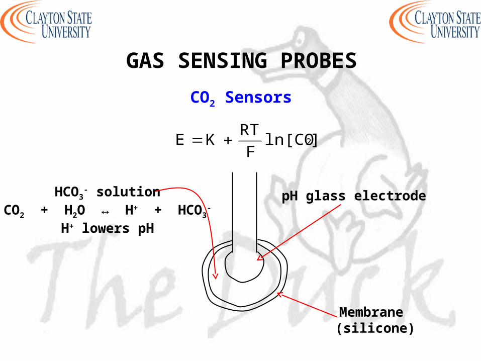
CO2 Sensors
]ln[COF
RTKE 2
pH glass electrodeHCO3- solution
CO2 + H2O ↔ H+ + HCO3-
H+ lowers pH
Membrane (silicone)
GAS SENSING PROBES

NH3 Sensors
- Consists of pH electrode covered by NH3 selective membrane (teflon or polyethylene)
- Electrolyte between electrode and membrane is NH4
+-KCl solution
- NH3 goes through membrane and raises pH
- Inner glass electrode senses changes in pH
- Increase in pH is proportional to amount of NH3 in sample
GAS SENSING PROBES

Other Gas Sensing Devices
NO2 and SO2
- Makes use of modified pH electrode
H2S- Makes use of S2- ISE or modified pH electrode
HF- Makes use of F- ISE or modified pH electrode
GAS SENSING PROBES

- Enzymes are proteins that catalyze chemical reactions in living things
- Based on coupling a layer of an enzyme with an electrode(enzyme is immobilized on an electrode)
- Electrode serves as a transducer
- Very efficient and extremely selective
IMMOBILIZED ENZYME MEMBRANE ELECTRODES

- Enzyme (biocatalytic) layer immobilized on an electrode
Electrode
Biocatalytic Layer
IMMOBILIZED ENZYME MEMBRANE ELECTRODES

Applications
- Useful for monitoring clinical, environmental, food samples
- For determination of glucose in blood (glucose sensors)
For amperometric sensing of ethanol (ethanol electrodes)
For sensing urea in the presence of urease enzyme (urea electrodes)
IMMOBILIZED ENZYME MEMBRANE ELECTRODES

- Known as ion-selective field effect transistors (ISFET)
- Are semiconductor devices
- Surface of transistor is covered with silicon nitride
- Absorbs H+ from solution (results in change of conductivity)
- Provides the ability to sense several ions (Na+, Ca2+, K+, pH in blood samples, etc)
- For detection of hydrocarbons and NOx in exhaust
SOLID-STATE DEVICES

- External reference electrode is required
- Does not require hydrating
- Has rapid response time
ExamplesNa+ ISFETNH3 ISFETCl- ISFET
SOLID-STATE DEVICES

- Employs a potential measuring device (handheld device)(high-impedance circuit)
- Example is the pH meter (or pIon meter)
- Designed to work with various electrodes
- Have built-in temperature measurement and compensation
- Three-point or more auto calibration
- Two-electrode system (auxiliary reference electrode and working electrode)
POTENTIOMETRY INSTRUMENTATION

APPLICATIONS OF POTENTIOMETRY
- Used as detectors for automated flow analyzers(flow injection systems)
- High-speed determination of blood electrolytes in hospitals(H+, K+, Cl-, Ca2+, Na+)
- For measuring soil samples (NO3-, Cl-, Li+, Ca2+, Mg2+)
- Coupling ion chromatography with potentiometric detection
- Micro ISEs as probe tips for SECM
- Column detectors for capillary-zone electrophoresis

- For studying chemical reactions (kinetics, equilibria, mechanism, solubility product constant, stability constant of complexes)
- For characterization of materials
- Quality control of raw materials and finished products
- Pharmaceutical and biological studies
- Elemental and molecular analysis
- Environmental monitoring
APPLICATIONS OF POTENTIOMETRY

- Electronics
- Electrochemical sensors
Advantages of controlled potential processes- High sensitivity and selectivity
- Very low detection limits- Wide range of electrode types
- Wide range of linearity- Portable and low cost instrumentation
APPLICATIONS OF POTENTIOMETRY

- Electrostatic technique
- Measurement of the current response to an applied potential
- Various combinations of potential excitations exist(step, ramp, sine wave, pulse strain, etc)
CONTROLLED POTENTIAL TECHNIQUES

Instrumentation
- Potentiostat (Voltammetric Analyzer)
- Electrochemical cell with a three-electrode systemWorking Electrode (WE)Reference Electrode (RE)
Counter/Auxiliary Electrode (CE/AE)
- Plotter
- Other components may be required depending on the type of experiment
CONTROLLED POTENTIAL TECHNIQUES

Potentiostat- Instrument that controls the potential at a working electrode
- Connects the three electrodes
Electrochemical Cell- Covered glass container of 5 – 50 mL volume
- Contains the three electrodes immersed in the sample solution
- Electrodes are inserted through holes in the cell cover
- N2 gas used as deoxygenated gas
CONTROLLED POTENTIAL TECHNIQUES

Working Electrode (WE)- Electrode at which the reaction of interest occurs
(Pt, Au, Ag, C)
Reference Electrode (RE)- Provides a stable and reproducible potential
- Independent of the sample composition(Ag/AgCl, SCE)
Counter/Auxiliary Electrode (CE/AE)- Current-carrying electrode made of inert conducting metal
(Pt wire, Graphite rod)
CONTROLLED POTENTIAL TECHNIQUES

- RE is placed as close as possible to WE to minimize potential drop caused by the cell resistance (iR)
- Flow cannot occur through RE hence the need for CE to complete the current path
- Current flows through solution between WE and CE
- Voltage is measured between WE and RE
CONTROLLED POTENTIAL TECHNIQUES

Electrochemical Cell
CE WERE
N2
Opening
Teflon cap
Glass container
CONTROLLED POTENTIAL TECHNIQUES

MASS TRANSPORT
- Three modes of mass transport
Diffusion- Spontaneous movement as a result of concentration gradient
- Movement from regions of high concentration to regions of low concentration

MASS TRANSPORT
- Three modes of mass transport
ConvectionTransport to the electrode by gross physical movement
Forced Convection- Driving force is an external mechanical energy
- Solution stirring or flowing- Electrode rotation or vibration
Natural Convection- Physical movement as a result of density gradient

MASS TRANSPORT
- Three modes of mass transport
Migration- Movement of charged particles along an electric field
- Charge is carried through the solution as a result of movement of ions

- Inert
- Decreases the resistance of the solution
- Eliminates electromigration effects
- Maintains a constant ionic strength
- Concentration range in usually 0.1 M – 1.0 M
- Should be in large excess of analyte concentration
SUPPORTING ELECTROLYTE

- Medium for electrochemical measurements
- Contains a supporting electrolyte
- Choice of solvent depends on the solubility and the redox activity of the analyte
Solvent Properties- Electrical conductivity
- Electrochemical activity - Chemical reactivity
SOLVENTS

- Purging with an inert gas for about 10 minutes
- Nitrogen gas is usually used
- Purging is done just before voltammetric measurements
- Necessary as oxygen complicates interpretation
Other Methods- Formation of peroxides followed by reduction of peroxides
-Reduction by addition of sodium sulfite or ascorbic acid
OXYGEN REMOVAL

- Method in which charge is measured
- Species being measured is converted quantitatively to a new species
The Methods Based on Electrolysis- Electrogravimetry
- Constant-potential coulometry- Constant-current coulometry (coulometric titrimetry)
Electrolysis- A process causing a thermodynamically nonspontaneous
oxidation or reduction reaction to occur by application of potential or current
COULOMETRY

Electrogravimetry
- Product of electrolysis is plated on a pre-weighed electrode
- Electrode is weighed again after process and the amountplated is determined by difference
- Metal dissolves from the anode and deposits on the cathode(electroplating, electrowinning, or electrorefining)
Examples of metals commonly determinedCd, Bi, Co, Cu, Sb, Zn, Ni, In, Ag
COULOMETRY

Controlled Potential Coulometry
- Three electrode system
- Permits applied potential pulse or ramp at the working electrode
- Metal elements are deposited as potential is increased which increases charge passing through cell
- The instrument is the coulometer which measures q
COULOMETRY

Controlled Potential Coulometry
Applications
- Used to eliminate interferences from other reactions that take place at different potentials
- Used to determine the number of electrons involved in a reaction
- Used for coulometric titrations
COULOMETRY
Conductometric Analysis
- Measures electrical conductivity between two electrodes by ions in solution
Applications- To determine the ionic content of drinking water,
deionized water, solvents, beverages
- Used as a detector for ion chromatography, HPLC
- Used for conductometric titrations (end point determination)
COULOMETRY

Instrumentation
Apparatus comprises of- Potentiostat with DC output voltage
- Inert cathode and anode- Stirring rod set-up
- Solution may be heated
- Working electrode can be either anode or cathode
- Controlled potential conditions
COULOMETRY

- Voltage between two electrodes is varied as current is measured
- Solid working electrodes are used
- Oxidation-reduction takes place at or near the surface of the working electrode
- Graph of current versus potential is obtained
- Peak current is proportinal to concentration of analyte
VOLTAMMETRY

VOLTAMMOGRAM
- Current versus potential plot
- Current on vertical axis and excitation potential on horizontal axis
- Electrode reactions involve several steps and can be complicated
- The rate is determined by the slowest step and depends on the potential range

- Involves linear scanning of potential of a stationary electrode using a triangular waveform
- Solution is unstirred
- The most widely used technique for quantitative analysis of redox reactions
Provides information on- the thermodynamics of redox processes
- the kinetics of heterogeneous electron transfer reactions- the kinetics of coupled reactions
CYCLIC VOLTAMMETRY

- Is a three electrode system
- Pretreatment (polishing) of working electrode is necessary
- The current resulting from an applied potential is measured during a potential sweep
- Current-potential plot results and is known as cyclic voltammogram (CV)
CYCLIC VOLTAMMETRY

CYCLIC VOLTAMMOGRAM (CV)
Triangular waveform (left) and CV (right) of ferricyanide

O + ne- ↔ R
- Assume only O is present initially
- A negative potential sweep results in the reduction of O to R(starting from a value where no reduction of O initially occurs)
- As potential approaches Eo for the redox process, a cathodic current is observed until a peak is reached
- The direction of potential sweep is reversed after going beyond the region where reduction is observed
CYCLIC VOLTAMMETRY

- This region is at least 90/n mV beyond the peak
- R molecules generated and near the electrode surface are reoxidized to O during the reverse (positive) scan
- Results in an anodic peak current
- The characteristic peak is a result of the formation of a diffusion layer near the electrode surface
- The forward and reverse currents have the same shape
CYCLIC VOLTAMMETRY

- Increase in peak current corresponds to achievement of diffusion control
Characteristic Parameters- Anodic peak current (ipa)
- Cathodic peak current (ipc)- Anodic peak potential (Epa)
- Cathodic peak potential (Epc)
CYCLIC VOLTAMMETRY

Reversible Systems
- Peak current for a reversible couple is given by the Randles-Sevcik equation (at 25 oC)
n = number of electronsA = electrode area (cm2)
C = concentration (mol/cm3)D = diffusion coefficient (cm2/s)
ν = potential scan rate (V/s)
1/21/23/25p νACDn10x2.69i
CYCLIC VOLTAMMETRY

Reversible Systems
ip is proportional to C
ip is proportional to ν1/2
- Implies electrode reaction is controlled by mass transport
ip/ic ≈ 1 for simple reversible couple
- For a redox couple
2
EEE pcpao
CYCLIC VOLTAMMETRY

Reversible Systems
- The separation between peak potentials
Vn
0.059EEΔE pcpap
- Used to determine the number of electrons transferred
- For a fast one electron transfer ∆Ep = 59 mV
- Epa and Epc are independent of the scan rate
CYCLIC VOLTAMMETRY

Irreversible Systems- Systems with sluggish electron transfer
- Individual peaks are reduced in size and are widely separated
- Characterized by shift of the peak potential with scan rate
Quasi-reversible Systems- Current is controlled by both charge transfer and mass transport
- Voltammograms are more drawn out
- Exhibit larger separation in peak potentials compared to reversible systems
CYCLIC VOLTAMMETRY

Applications
For analyzing - drugs
- herbicides- insecticieds
- foodstuff additives- pollutants
CYCLIC VOLTAMMETRY

- Voltammetry in which the working electrode is dropping mercury
- Makes use of potential ramp
- Conventional DC
- Wide cathodic potential range and a renewable surface
- Hence widely used for the determination of many reducible species
POLAROGRAPHY

- Initial potential is selected such that the reaction of interest does not take place
- Cathodic potential scan is applied and current is measured
- Current is directly proportional to the concentration-distance profile
- Reduction begins at sufficiently negative potential[concentration gradient increases and current rises
rapidly to its limiting value (iL)]
POLAROGRAPHY

- Diffusion current is obtained by subtracting response due to supporting electrolyte (background current)
- Analyte species entering region close to the electrode surface undergo instantaneous electron transfer reaction
- Maximum rate of diffusion is achieved
- Current-potential plot provides polarographic wave (polarogram)
POLAROGRAPHY

DC POLAROGRAPHY
- Three electrode system
WE = dropping mercury electrode (DME)
CE = Pt wire or foil
RE = SCE

The Ilkovic Equation
DC POLAROGRAPHY
D = cm2/s C = mol/cm3 m = g/s t = s
iL is current at the end of drop life (the limiting current)
iL is a measure of the species concentration
Ctm708nDi 1/62/31/2
L

Half Wave Potential (E1/2)
- Potential at which the current is one-half its limiting value
- E1/2 is independent of concentration of species
DC POLAROGRAPHY
DR = diffusion coefficient of reduced speciesDO = diffusion coefficient of oxidized species
- Experimental E1/2 is compared to literature values to identify unknown analyte
1/2
O
Ro1/2 D
Dlog
nF
RTEE

Half Wave Potential (E1/2)
At 25 oC
DC POLAROGRAPHY
- A graph of E versus log[(iL-i)/i] is linear if reaction is reversible(Nernstian behavior)
- Slope = 0.05916/n and intercept = E1/2
E = E1/2 when [Ox] = [Red]
i
ilog
n
0.05916EE L
1/2i

STRIPPING ANALYSIS
Two step technique
1. Deposition Step (Preconcentration step)- Involves preconcentration of analyte species by reduction
(anodic stripping) or oxidation (cathodic stripping) into a mercury electrode
2. Stripping Step- Measurement step
- Rapid oxidation or reduction to strip the products back into the electrolyte

STRIPPING ANALYSIS
- Very sensitive for trace analysis of heavy metals
- Favorable signal to background ratio
- About four to six metals can be measured simultaneously at levels as low as 10-10 M
- Low cost instrumentation
- There are different versions of stripping analysis depending on the nature of the deposition and stripping steps

STRIPPING ANALYSIS
Anodic Stripping Voltammetry (ASV)
- The most widely used stripping analysis
- Preconcentration is done by cathodic deposition at controlled potential and time
- Metals are preconcentrated by electrodeposition into a small-volume Hg electrode
- Deposition potential is usually 0.3 – 0.5 V more negative than Eo for the analyte metal ion

STRIPPING ANALYSIS
Anodic Stripping Voltammetry (ASV)
- Metal ions reach the Hg electrode surface by diffusion and convection
- Electrode rotation or solution stirring is employed to achieve convection
- Metal ions are reduced and concentrated as amalgams
Mn+ + ne- + Hg → M(Hg)
- Hg film electrodes or Hg drop electrodes may be used

STRIPPING ANALYSIS
Anodic Stripping Voltammetry (ASV)
Following preselected deposition period:
- Forced convection is stopped
- Anodic potential scan is employed (may be linear or pulse)
- Amalgamated metals are reoxidized (stripped off electrode)
- An oxidation (stripping) current then flows
M(Hg) → Mn+ + ne- + Hg

STRIPPING ANALYSIS
Cathodic Stripping Voltammetry (CSV)
- Mirror image of ASV
- Involves anodic deposition of analyte and subsequent stripping by a potential scan in the negative direction
An- + Hg ↔ HgA + ne-
(Deposition to the right and stripping to the left)
- Useful for measuring organic and inorganic compounds that form insoluble salts with Hg (thiols, penicillin, halides, cyanides)