dr. lee jones senior accelerator physicist
TRANSCRIPT

Dr. Lee Jones
Senior Accelerator Physicist
Accelerator Science and Technology Centre
STFC Daresbury Laboratory
Photoinjectors: A General Overview
1

Over the years ……
The synchrotron The cyclotron
2

IOT Rack
Alice Diagnostics
Beamline
RF Distribution
EMMA: The world’s first non-scaling fixed-field alternating gradient accelerator (nsFFAG)
Credit: STFC

Booster
Dipole
Compression
Chicane
LINAC
500 kV
Power
Supply
Gun
Photoinjector
Laser
Nominal Gun Energy: 350 keV Injector Energy: 8.35 MeV Final Beam Energy: 35 MeV
RF Frequency: 1.3 GHz Rep. Rate: 81.25 MHz Bunch Charge: 80 pC Average Current: 6.5 mA
Moveable
Arc
ALICE: Europe’s first energy-recovery linear accelerator (ERL)
Single-pass machine dynamic aperture does not define beam brightness
Credit: STFC
5
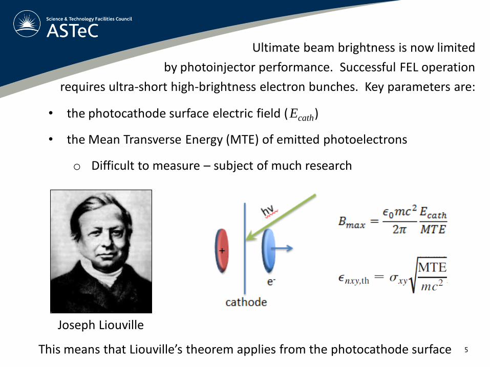
Joseph Liouville
Ultimate beam brightness is now limited
by photoinjector performance. Successful FEL operation
requires ultra-short high-brightness electron bunches. Key parameters are:
• the photocathode surface electric field ( Ecath )
• the Mean Transverse Energy (MTE) of emitted photoelectrons
o Difficult to measure – subject of much research
This means that Liouville’s theorem applies from the photocathode surface

6
• What is a an electron gun?
o Combines electron source with beam conditioning
and a high voltage for acceleration
• Possible electron gun technologies:
o Hot filament
o Field-emission nano tip array
o Carbon nanotubes
o Magneto-optical trap
o Plasmonic surfaces & structures
o Photoinjector
Photocathode
Illumination by pulsed laser
Emittance compensation + accelerating stage(s)
An electron gun ? …… No
A high-performance electron machine gun !!!
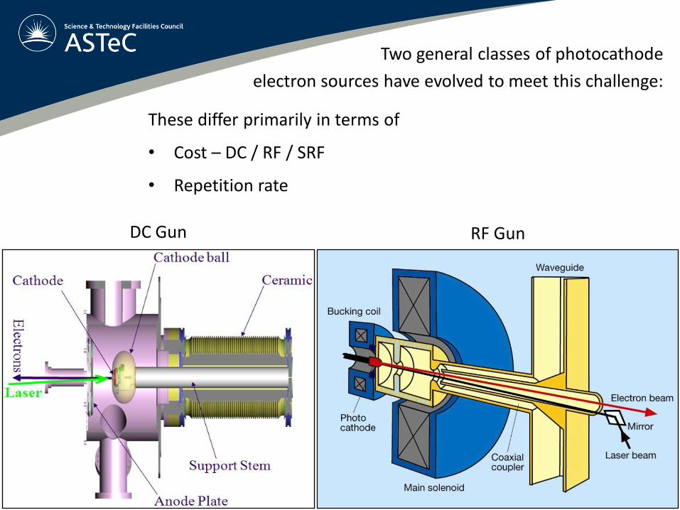
DC Gun RF Gun
Two general classes of photocathode
electron sources have evolved to meet this challenge:
These differ primarily in terms of
• Cost – DC / RF / SRF
• Repetition rate

Field
strength, Ecath Technology 0.01 nC 0.1 nC 1.0 nC
10 MV/m DC gun 0.11 0.34 1.08
20 MV/m VHF gun 0.08 0.24 0.77
50 MV/m L-band gun 0.05 0.15 0.48
100 MV/m S-band gun 0.03 0.11 0.34
DC/RF Gun performance FOM:
q = bunch charge [C]
Ei = initial energy [eV]

The photocathode family tree

10
DC Guns: Technical challenges
• Power supply ripple
• Vacuum requirements – dependent on cathode
• Back-ion bombardment
• Dark current / field emission
• HV Conditioning – use of He/Kr during processing
• Insulating ceramic – electrical and mechanical loading

PSU ripple drives fluctuations in beam emittance, bunch shape, bunch arrival
time, and average energy after full acceleration.
Phase change at a distance L away from the gun caused by gun voltage variation:
where j is in radians, f is the RF frequency, c is the speed of light, and
Vgun / Vgun is relative ripple of the gun voltage.
In terms of RF phase, variations of ± 1° are tolerable for low emittance beams.
At 1.3 GHz, ± 1° in phase is approximately ± 2 ps in arrival time, corresponding to
a shift of ± 450 V (0.18 %) 1 metre from a 250 kV gun.
The voltage ripple needs to be specified over the frequency ranges present in
the power supply, typically up to 60 kHz (or more) for switching power supplies. 11
3
12
( )
gun
gun
VLf
c V
j
DC Guns: Technical challenges
Power supply ripple

12
• Much easier to pump a DC gun chamber than an RF gun
• Photocathodes used in a DC gun generally have very high vacuum requirements
o Requires use of high-quality materials and good engineering practices
o Pumping to XHV achieved through use of large ion pumps and NEG coatings,
and baking for a long time
• Vacuum degraded by gun operations, and in-situ photocathode preparation
o Maintenance of good gun vacuum requires an external photocathode
preparation facility (PPF)
• Poor vacuum leads to contamination of the photocathode, and thereby a drop in
the Quantum Efficiency (Q.E.)
• Poor vacuum also increases the back-ion bombardment rate, reducing
photocathode lifetime and the maximum achievable Q.E.
DC Guns: Technical challenges
Vacuum considerations

13
• Back-ion bombardment is a major challenge in DC guns
• It degrades Q.E. and damages the cathode surface
• Reduced by good vacuum, but fundamentally un-avoidable
• Worst effects occur within a few mm of the photocathode surface
• Positive bias on the anode suppresses back-ions from downstream
DC Guns: Technical challenges
Back-ion bombardment
Courtesy Joe Grames, JLab

Photocathode Preparation Facility for the ALICE ERL DC photocathode gun
Photocathode gun
500 kV DC power supply
PPF - Photocathode Preparation Facility
The use of a PPF confers several
operational advantages:
• Improved environment for
photocathode activation
• Reduced accelerator down-time for
photocathode activation, permitting
operations with high bunch charge
• Improved gun operating environment
o Better gun vacuum
o Reduces contamination of the
gun HV electrodes
• Permits accelerator operation with
different types of photocathodes
DC Guns: Technical challenges
Courtesy Boris Militsyn, DL

Right: Measurements of field emission
between two single crystal niobium
electrodes, polished with BCP process
and HV conditioned using Kr.
Courtesy Matt Poelker, JLab
DC Guns: Technical challenges
High voltage conditioning
• Potentially dangerous, but essential for stable operation of a DC gun
• HV electrodes must be ‘trained’ to support high voltages
• Conditioning necessary to desired operating voltage + 10 % as a minimum
• Use of Kr during HV conditioning is beneficial for new HV electrodes
Voltage [kV]
Fiel
d e
mis
sio
n c
urr
ent
[pA
]
16
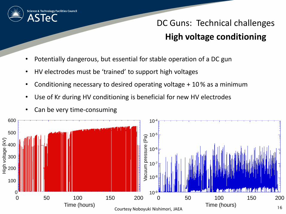
DC Guns: Technical challenges
High voltage conditioning
• Potentially dangerous, but essential for stable operation of a DC gun
• HV electrodes must be ‘trained’ to support high voltages
• Conditioning necessary to desired operating voltage + 10 % as a minimum
• Use of Kr during HV conditioning is beneficial for new HV electrodes
• Can be very time-consuming
Time (hours)
0 50 200 100 150
Time (hours)
0 50 200 100 150 10-9
Va
cu
um
pre
ssu
re (
Pa
)
10-8
10-7
10-6
10-5
10-4
0
100
300
500
600
Hig
h v
olta
ge
(kV
)
200
400
Courtesy Noboyuki Nishimori, JAEA

17
DC Guns: Technical challenges
Dark current & Field emission
• Some dark current is un-avoidable in any photocathode gun
o Intrinsic property of the photocathode, affected by photocathode choice
Measurements show that Cu and Cs2Te have similar levels of dark
current emission, but Cs3Sb exhibits much higher dark current levels.
Courtesy Christoph Hessler, CERN

18
DC Guns: Technical challenges
Dark current & Field emission
• Some dark current is un-avoidable in any photocathode gun
o Intrinsic property of the photocathode, affected by photocathode choice
• Low-level field emission is also unavoidable, but must be managed
o Careful design of HV surfaces and maximum electric field strength
o Clean conditions during assembly
o Effective HV conditioning
• Intense or sudden field emission can be catastrophic
o Tracking along ceramic – short circuit
o Punch-through causing a leak
• Biased (floating) anode plate permits dark current measurements

19
DC Guns: Technical challenges
Insulating ceramic
• Insulating ceramic must withstand extreme DC voltage and a large mechanical
load whilst maintaining large pressure difference
• It should not be a perfect insulator !!!
• Surface coating or bulk doping for high resistivity

20
DC Guns: Technical challenges
Insulating ceramic
• Insulating ceramic must withstand extreme DC voltage and a large mechanical
load whilst maintaining large pressure difference
• It should not be a perfect insulator !!!
• Surface coating or bulk doping for high resistivity
In-air HV cable
Courtesy Carlos Hernandez-Garcia, JLab

• Insulating ceramic must withstand extreme DC voltage and a large mechanical
load whilst maintaining large pressure difference
• It should not be a perfect insulator !!!
• Segmented ceramic with guard rings
21
DC Guns: Technical challenges
Insulating ceramic
cathode
anode
laser
e-beam
stem
electrod
e
seg
men
ted
ceram
ics
500 kV Photocathode gun at JAEA
Courtesy Noboyuki Nishimori, JAEA
22
RF Guns: Technical challenges
Some common ground
RF guns share some of the technical challenges described for DC guns:
• Photocathode integration
o Vacuum environment & electric field disruption
o Different photocathode ‘standards’
o Collaborations difficult – vacuum suitcases needed
• DC Ripple / effective RF ripple – amplitude and timing
o Cavity temperature stability
• Symmetric and uniform electric field
• Dark current / field emission
• Synchronisation of the photoinjector drive laser to the RF via a master clock
o Use of optical clocks for distributed timing – Holgar Schlarb, DESY
o Problems increase with the size of the facility
23
• Arguably the most critical factor in a photocathode/photoinjector gun
• Very difficult to measure accurately !!!
o Amplitude noise indistinguishable from phase noise
• Best-practice for phase noise measurements in lasers establish by
Scott et. al: IEEE J. Sel. Top. Quan. Elec.; 7(4), 641, 2001
DC & RF Guns: Drive Lasers
Synchronisation with the RF

24
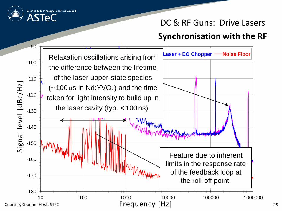
Measurements on ALICE: Initially, the noise floor of the HP3047A system was measured
by feeding the same signal from a Wenzel low-noise 81.25 MHz RF oscillator into both
inputs of the low-noise mixer in quadrature. The laser was then synchronised to the
oscillator, and the laser output fed back to a low-noise mixer via a fast photodiode.
DC & RF Guns: Drive Lasers
Synchronisation with the RF
Courtesy Graeme Hirst, STFC
-180
-170
-160
-150
-140
-130
-120
-110
-100
-90
10 100 1000 10000 100000 1000000
Laser Laser + EO Chopper Noise Floor
Frequency [Hz] 25
Relaxation oscillations arising from
the difference between the lifetime
of the laser upper-state species
(~ 100 ms in Nd:YVO4) and the time
taken for light intensity to build up in
the laser cavity (typ. < 100 ns).
Feature due to inherent
limits in the response rate
of the feedback loop at
the roll-off point.
DC & RF Guns: Drive Lasers
Synchronisation with the RF
Sig
na
l le
vel
[dB
c/H
z]
Courtesy Graeme Hirst, STFC

-180
-170
-160
-150
-140
-130
-120
-110
-100
-90
10 100 1000 10000 100000 1000000
Laser Laser + EO Chopper Noise Floor
Frequency [Hz] 26
DC & RF Guns: Drive Lasers
Synchronisation with the RF
Sig
na
l le
vel
[dB
c/H
z]
Courtesy Graeme Hirst, STFC
Measurement indicates
650 fs RMS phase noise

27
Extinction ratio is critical in a non-CW machine
DC & RF Guns: Drive Lasers
Extinction ratio
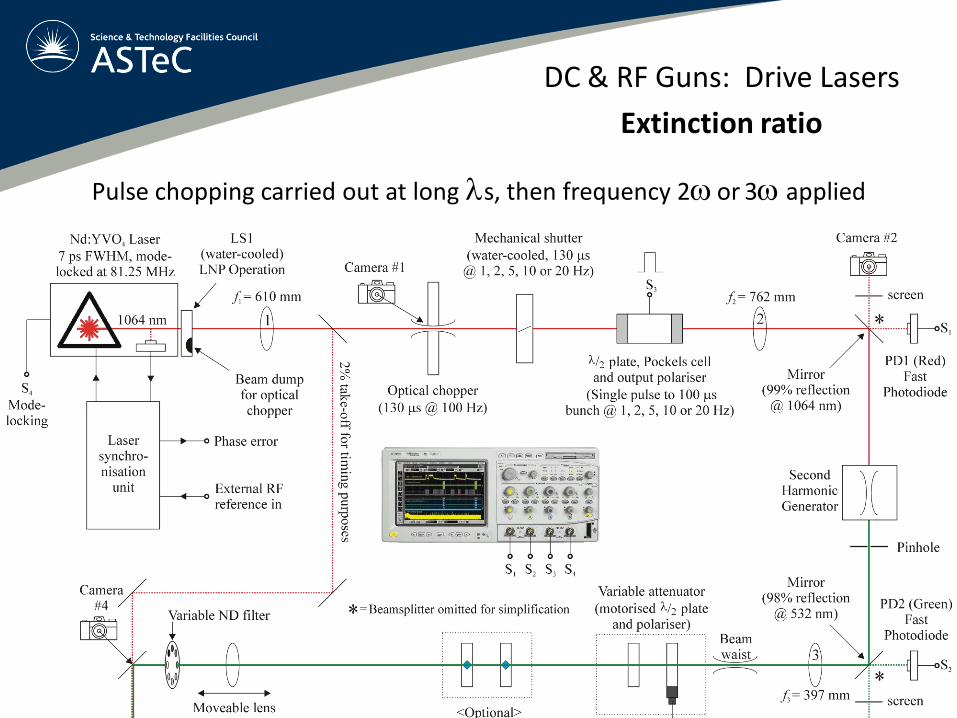
Pulse chopping carried out at long ls, then frequency 2w or 3w applied
DC & RF Guns: Drive Lasers
Extinction ratio
Pulse chopping carried out at long ls, then frequency 2w or 3w applied
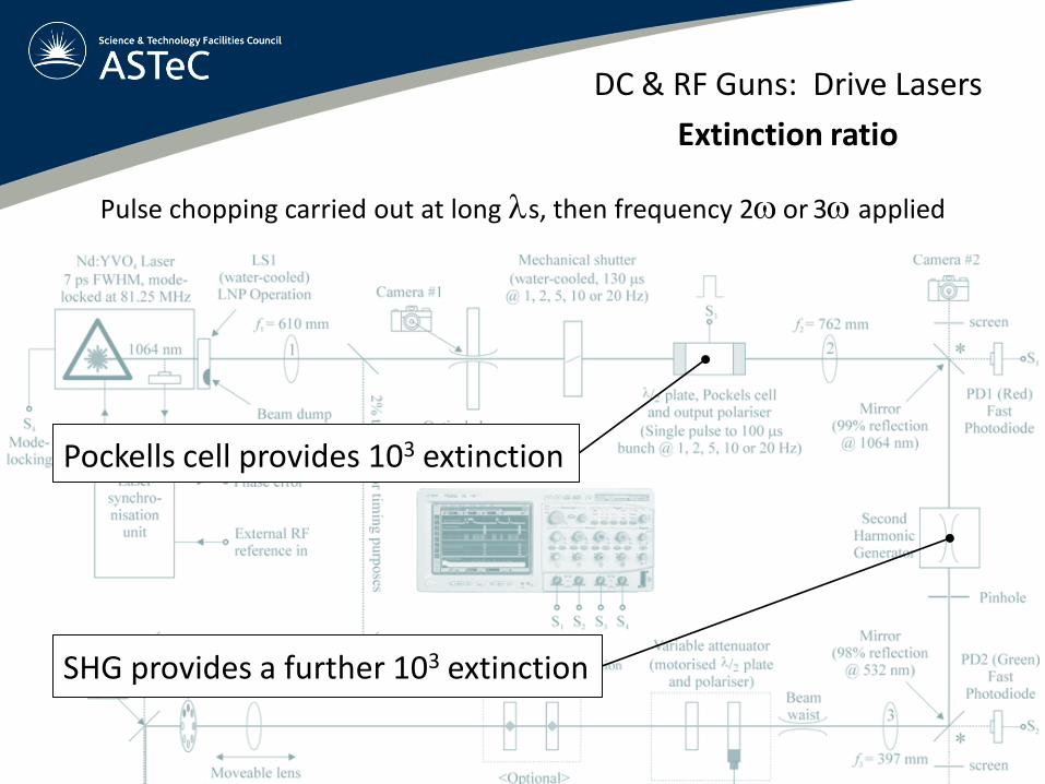
DC & RF Guns: Drive Lasers
Extinction ratio
Pockells cell provides 103 extinction
SHG provides a further 103 extinction
30
DC & RF Guns: Drive Lasers
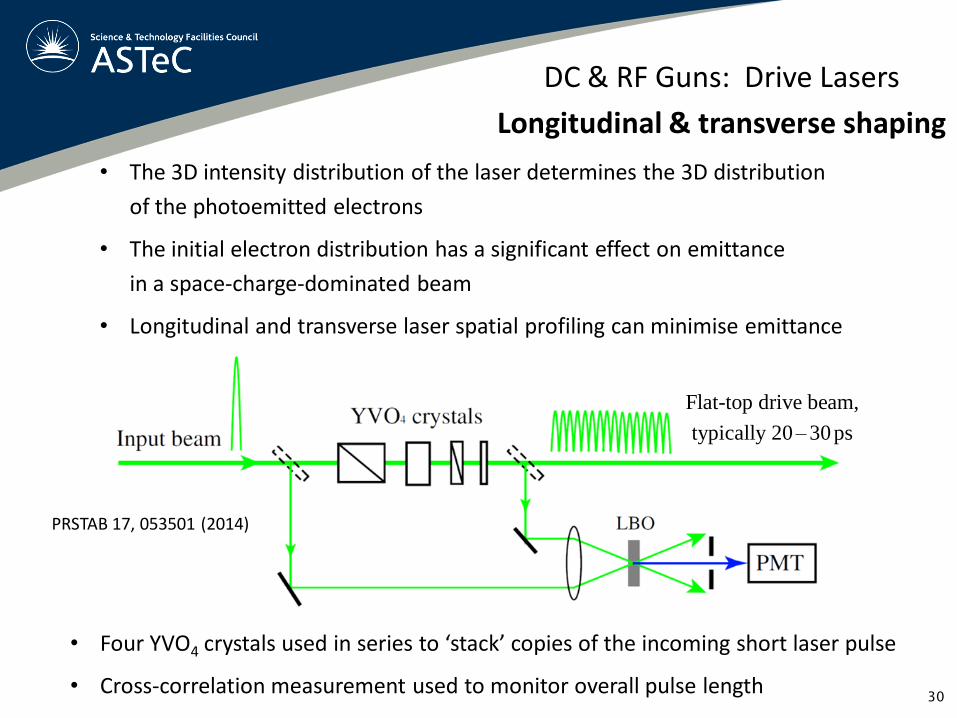
Longitudinal & transverse shaping
• The 3D intensity distribution of the laser determines the 3D distribution
of the photoemitted electrons
• The initial electron distribution has a significant effect on emittance
in a space-charge-dominated beam
• Longitudinal and transverse laser spatial profiling can minimise emittance
• Four YVO4 crystals used in series to ‘stack’ copies of the incoming short laser pulse
• Cross-correlation measurement used to monitor overall pulse length
Flat-top drive beam,
typically 20 – 30 ps
PRSTAB 17, 053501 (2014)

31
DC & RF Guns: Drive Lasers
Longitudinal & transverse shaping
A non-uniform laser beam generates a non-
uniform electron beam which expands at a
rate linked to the plasma period.
The best electron beam is achieved with a
truncated Gaussian transverse laser beam.
Emittance tests on
various transverse
laser beam profiles
PRSTAB 5, 094203 (2002)
Transverse beam dimension [mm]
Transverse beam dimension [mm]
Transverse beam dimension [mm]
Transverse beam dimension [mm]
Transverse beam dimension [mm]

32
DC & RF Guns: Drive Lasers
Good practice
• Off-centre illumination to avoid worst effects of back-ion bombardment
o Cornell claim no detriment to emittance for a 0 – 4 mm laser offset
• Use of a virtual cathode
o Concept inspired by DESY Zeuthen
o Splits off small fraction of drive laser beam and images this on a screen

• 167 W IR laser power at 1.3 GHz (fibre amplifier)
• 124 W green laser power at 1.3 GHz
• 800 fs micropulses, stretchable to 80 ps ‘stacked’
• Further power increases possible
“Enabling next-generation high-current X-ray sources”
Courtesy Bruce Dunham, CHESS
The Cornell 1.3 GHz, 1 ps rod fibre amplifier
photoinjector drive laser
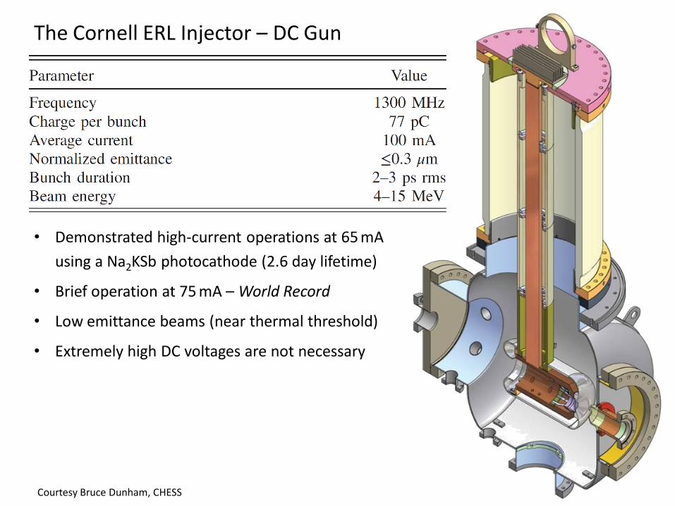
The Cornell ERL Injector – DC Gun
• Demonstrated high-current operations at 65 mA
using a Na2KSb photocathode (2.6 day lifetime)
• Brief operation at 75 mA – World Record
• Low emittance beams (near thermal threshold)
• Extremely high DC voltages are not necessary
Courtesy Bruce Dunham, CHESS

Anode electrode
2 welded bellows
Gate valve
• Gun originally designed for 750 kV operation
• Cathode field is crucial
• Translatable anode to tailor the cathode field strength
• 20 - 50 mm adjustable gap
Courtesy Bruce Dunham, CHESS Small gap, 20 mm Large gap, 50 mm

The Cornell ERL Injector – DC Gun
• Demonstrated high-current operations at 65 mA
using a Na2KSb photocathode (2.6 day lifetime)
• Brief operation at 75 mA – World Record
• Low emittance beams (near thermal threshold)
• Extremely high DC voltages are not necessary
• Simulations + optimisations match experiments
• Halo / beam loss can be maintained below
1 part in 107 to 108
• Photocathodes are still the key challenge
Courtesy Bruce Dunham, CHESS

37
Thank you for listening
Credits to colleagues for material used in this presentation:
Dr. Bruce Dunham, Cornell
Dr. Joe Grames, JLab
Dr. Carlos Hernandez-Garcia, JLab
Dr. Christoph Hessler, CERN
Dr. Graeme Hirst, STFC (ret)
Dr. Boris Militsyn, STFC
Dr. Noboyuki Nishimori, JAEA
Dr. Matt Poelker, JLab
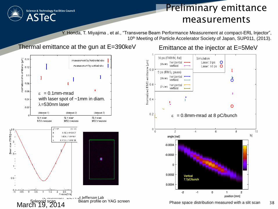
Preliminary emittance
measurements
March 19, 2014
N. Nishimori EIC14 at Jefferson Lab
Y. Honda, T. Miyajima , et al., “Transverse Beam Performance Measurement at compact-ERL Injector”,
10th Meeting of Particle Accelerator Society of Japan, SUP011, (2013).
Thermal emittance at the gun at E=390keV
= 0.1mm-mrad
with laser spot of ~1mm in diam.
l=530nm laser
Emittance at the injector at E=5MeV
Phase space distribution measured with a slit scan Solenoid scan
= 0.8mm-mrad at 8 pC/bunch
Beam profile on YAG screen 38

39
DC Guns: Drive Lasers
Polarised electrons
• Polarised emission from the 4s1/2 band when illuminating GaAs (100)
• l ~ 800 nm RCP generates mj = +1 and LCP generates mj = -1
• Clebsch-Gordan coefficients give likelihood of transition
• Transitions from mj = -3/2 state 3 times more likely than those from mj = -1/2 state
Polarisation, P = (1 – 3)/(1 + 3)
= - 0.5
Courtesy Carlos A.E.R. Malins, STFC

Feedback Stabilization
17 July 2014 C. Hessler 40
Result: Improvement of intensity stability (laser beam) and charge
stability (electron beam) by a factor of 3 down to 0.4% rms and 1% rms