dýrafjarðargöng – sérverklýsing (technical specification) · dýrafjarðargöng technical...
TRANSCRIPT

Dyrafjarðargong – serverklysing
(Technical Specification)
English translation of chapters: 8.03 Tunnel Excavation 8.04 Drilling and Grouting 8.05 Rockbolts 8.06 Sprayed Concrete 8.07 Waterproof- and frost lining
Technical specification Dýrafjarðargöng
Tunnel excavation
1/9
8.02. Tunnel excavation.
General specification 22.5 Drill and blast tunnel, excavation a) The work item includes all materials and all work for the excavation (blasting) as specified. Included are among others, drilling, charging and explosives, blasting, mucking, hauling, tipping and sorting of material, finishing of surfaces, scaling and chiselling, regardless whether it is made along with the excavation or later, e.g. in connection with final rock support of the tunnel, placing pipes for water, and electricity, lighting and ventilation, measurements and testing.
b) Explosives and detonators must be appropriate for the rock and be of a type commonly used in tunnelling and causes minimum disruption to the rock outside the drilled cross section of tunnel.
Explosive with a limited explosive energy shall be used in perimeter holes (pipe charge, reduced loading, or blasting cord). Next row of holes within the perimeter holes shall also be charged with explosive of limited power in proportion to the distance from the perimeter holes.
c) Boreholes in the perimeter should normally lie between the design line of excavation and drilling limit, unless the Owner´s Representative (OR) approves otherwise. The distance between boreholes on the perimeter of the cross section shall be adjusted to the geological conditions and not be greater than 0.6 m. The distance between the perimeter holes and the next row of boreholes hole shall never be greater than 0.9 m, unless it has been shown that greater distance does not harm the rock outside design perimeter and has been approved by the OR.
Under certain conditions it might be necessary to extend the cross section to create more space for extensive rock reinforcement. The excavation for extended space for rock reinforcement shall only be performed when so instructed by the OR.
Necessary safety precautions to protect workers are required during blasting work. Rock support at tunnel face and temporary rock support is assumed during excavation work of tunnel to ensure security and stability of the rock, see work items 25.2 and 25.4. Temporary rock support shall follow the tunnel excavation and unsupported rock that shall never extend more than 15 meter from the tunnel face.
During the tunnel excavation the tunnel shall be lighted, ventilated and drained for water as not to interfere with the work in the tunnel. The Contractor must also provide portable lights (lamps / lanterns) for specific lighting in places inside the tunnel as the OR requires for inspection and where testing takes place.
The Contractor shall provide for approval by the OR the calculations and preliminary design of the ventilation system before tunnel excavations starts.
Working condition in the tunnel shall be at the best and at the least in accordance with the following referenced in the order they are listed:
Håndbok nr. 3 Arbeidsmiljø under fjord (Norsk Forening for Fjellsprengningsteknikk,2000).
Jarðgangagerð 5. Leiðbeiningar um aðbúnað, hollustuhætti og öryggi. (Guidelines on working conditions, health-and safety measures). Vinnueftirlit ríkisins, júní 1984.

Technical specification Dýrafjarðargöng
Tunnel excavation
2/9
Explosives and blasting plans shall be approved by the Owners Representative (OR). Blasting shall only be carried out in quantity, method and magnitude as approved. The OR can demand a change in the tunnelling method if he concludes that the blasting method of the Contractor causes excessive disruption of the rock outside the design perimeter of the excavation. Before blasting the OR shall be advised with due notice, as further detailed by the OR.
Necessary precautions shall be done to maintain as possible undisturbed rock outside the blasting limit. Drilling rig with automatic direct drilling guidance system shall be used and blasting of the tunnel shall be with a technique that suits for the rock. Any damage caused by poor work of the Contractors or abnormal disruption of the rock outside the excavation line, the Contractor shall remedy with no cost to the Owner, unless otherwise approved by the OR.
The Contractor shall carefully scale the rock surface in the tunnel at the face after each blast, and behind the face elsewhere in the tunnel as needed, to prevent damage due to falling rock. Loose stones and blocks of rock on the rock surface, shall be removed with a ripper rod, special rods or other methods that do not cause further distortion of the cross section drilled. If there is a significant time gap between rock blasting (excavation) and concrete spraying, a repeated scaling might be necessary before spraying concrete or at the completion of tunnel work, if the rock shall not be concrete sprayed.
If a poor rock is encountered on the tunnel route it might be necessary to reduce spacing between boreholes, change the charging of holes, shorten the drilling depth (rounds) and / or splitting rounds apart. Possibly excavation has to be done without blasting where rock is very fractured and poor. Short blasting rounds at tunnel entrances shall be assumed independent of rock type. If a blasting rounds needs to be split up it shall be included in the unit price.
Excavated materials to be used in the work shall be sorted and stockpiled at approved tip sites or at storage area near tunnel openings (portals) as shown on the drawings and as specified. If necessary, the tip area shall be cleaned of non-usable surface materials to avoid mixing of those with the piled material.
Excavated materials from tunnels that is unsuitable for the work shall be placed and piled for later use at the tip area as shown in the drawings and/or as directed.
The OR may approve the construction of side niches and lay-by’s or spaces outside of designed cross section if the Contractor considers it necessary for his own convenience. There are limitations on shape of such niches to meet requirements for safety and appearance. All cost of excavation and rock support for the Contractor´s convenience shall be included in the payment for the tunnel excavation.
d) The Contractor shall submit his plan for excavation of tunnels for OR´s approval. The plan shall cover all items relevant to tunnel excavations, blasting rounds in full length or half rounds. Details on the drilling plan, type of explosives and length of blasting rounds, method of excavation and mucking and hauling of material, disposal areas, care of water, method of scaling, temporary rock support, ventilation, lighting, environmental, safety and health measures and other relevant issues.
During the tunnel excavation the Contractor shall document each blasting rounds, length of tunnel excavated and volume, drilling and loading time of every blasting rounds, ventilation time after blasting, time for mucking and hauling, scaling and rock support of tunnel. Furthermore, the amount of explosives shall be documented, deviations from the approved drilling plan etc. as prescribed. This documentation shall be available for the OR daily. Temperature of incoming leakage water at the face shall be recorded on weekly basis.
Technical specification Dýrafjarðargöng
Tunnel excavation
3/9
The Contractor shall verify by regular surveying that the tunnel is correctly excavated. During the excavation of tunnel, the Contractor shall survey the direction and cross section of the tunnel and scan the tunnel before applying sprayed concrete with appropriate density of survey points to verify that the tunnel is everywhere excavated to or beyond excavation design lines and there is nowhere protruding rock within the design line. Sections with 5 m interval shall be submitted. Deviation of excavation shall be shown on flattened map (cf. “Kortlagningu á jarðfræði og styrkingum ganga) Comparable surveying shall be done after applying sprayed concrete, see 25.4 Sprayed concrete. If the Contractor finds underbreakage he shall immediately mark the location and correct as soon as possible. Surveying measurement shall be submitted weekly to the OR, unless otherwise agreed. For reference, 10-16 mm steel rod or pin shall be placed in one wall of the tunnel at 20 m intervals. The rod shall be 1 m above the centre-line of the road.
The Contractor shall, in cooperation with the OR install vibration measuring instrument on nearby buildings, at up to 600 metres distances from the tunnel portals, for measuring vibration from blasting work.
The Contractor shall in cooperation with the "Vinnueftirlitið"(Administration of Occupational Safety and Health) measure pollutants on a regular basis to verify that the requirements for air pollution in the tunnel is fulfilled and submit this to the OR.
The Contractor shall assist the OR in installation of special instruments and provide assistance with measurements in the tunnel, such as measurements of tunnel rock wall deformations due to rock stress, if requested.
e) The design cross section is the minimum cross section of tunnel for use, i.e. inside water shielding and frost protections.
Design line of excavation is defined in the Contract documents as designed blasted cross section of the tunnel. Design lines of excavation are payment limits of excavation.
Drilling limit of excavation is defined to be 0,3 m outside the design line of the excavation. The perimeter bore holes of the blasted cross section shall be located with a maximum of 0,10 m deviation from the approved blasting plan and never within the design line of excavation. Drilling deviation of perimeter holes outside the design limit should normally not exceed 5% of the depth of the bore hole or be more than 0,3 m beyond the design line of the excavations.
Over-break line is defined limit for determination of the geological overbreak. This limit is defined minimum 0,60 m outside the designed cross section of excavation or 0,30 m outside the drilled cross section, if that is larger. Overbreak to be considered for payment needs to be more than 10% of the blasted cross section at each location. Overbreak in the tunnel floor is not recognised.
Item 12. 22.51 Excavation full round. a) This work item includes all materials and all work on tunnel excavation (blasting) within design line with lay-bys (niches) for each round in length that is longer than 3.0 m, as specified. Included is i.e., drilling, charging and explosives, blasting, mucking, hauling of excavation material, tipping and sorting of excavated material, finishing of surfaces, scaling and chiselling, whether performed simultaneously with excavation or later, e.g. at final support of the tunnel, placing of pipes for water and electricity, lighting and ventilation, measurements and testing.
Technical specification Dýrafjarðargöng
Tunnel excavation
4/9
c) The tunnel shall be excavated from both ends to highest point. Excavated material shall be sorted as possible for use in road embankments and sub base.
f) Payment is based on designed volume of undisturbed rock.
Unit: m3.
Item 13. 22.52 Excavation shortened rounds. a) This work item includes all materials and all work on tunnel excavation (blasting and excavation without blasting) within design line for each round in length that is equal or shorter than 3,0m, and possible division of round, as specified. Included is i.e., drilling, charging and explosives, blasting, mucking, hauling of excavation material, tipping and sorting of excavated material, finishing of surfaces, scaling and chiselling, whether performed simultaneously with excavation or later, e.g. at final support of tunnel, placing of pipes for water and electricity, lighting and ventilation, measurements and testing.
c) This work item shall only be used for difficult rock conditions pending approval from OR. The tunnel shall be excavated from both ends to highest point. Excavated material shall be sorted as possible for use in road embankments and sub base.
f) Payment based on designed volume of undisturbed rock.
Unit: m3.
Item 14. 22.53 Excavation of side chamber. a) This work item includes all materials and all work on excavation (blasting) of side chambers outside the tunnel design cross section with lay-bys as specified. Included is i.e., drilling, charging and explosives, blasting, mucking, hauling of excavation material, tipping and sorting of excavated material, finishing of surfaces, scaling and chiselling, whether performed simultaneously with excavation or later, e.g. at final rock support of tunnel, placing pipes for water and electricity, lighting and ventilation, measurements and testing.
c) Excavation of technical chambers falls under excavation of side chambers. Size and shape of the chamber is shown on drawings. The Contractor can suggest a different form, if he considers that in his interest, such as to get rid of placing concrete at rock walls. Alternative proposals are only considered if it is proven that the change will not increase Owner´s cost.
Excavation of side chambers can take place anywhere in the tunnel during the construction period.
f) Payment is based on designed volume of undisturbed rock.
Unit: m3
Item 15. 22.54 Excavation outside design line. a) This work item includes all materials and all work on the excavation (blasting), outside the design lines of excavation if needed to install increased reinforcements, piping, manholes, ventilation equipment or other equipment in the tunnels, also excavations in weak rock in tunnel floor if needed to place thicker sub bases as prescribed. Included is i.e., drilling, loading and explosives, blasting, loading, transportation of excavation material, stockpiling and sorting of excavated material, finishing of surfaces, scaling and chiselling, whether
Technical specification Dýrafjarðargöng
Tunnel excavation
5/9
performed simultaneously with excavation or later, channelling for water and electricity, lighting and ventilation, measurements and testing.
c) Excavation according to this payment-item may occur behind the advancing tunnel face, anywhere in the tunnels during construction period.
f) Payment is based on designed volume into natural solid rock.
Units: m3
Item 16. 22.55 Geological over-breakage. a) This work item includes work to remove and transport material that has been approved as a geological over-break. Included in the cost of this item is scaling of loose rock within the over-breakage area as well as all delays on tunnel excavation that may occur as a result of over-break.
f) Payment is based on the agreed quantity. Unit price shall maximum be 20% of unit price for the work item 22:51, Excavation full round.
Payment for the geological over-break will only be approved if the following conditions are met:
• Over-breakage is above the excavation design line in the tunnel floor. • Over-breakage is outside the over-breakage limit and is more than 10% of the design
cross section. • Drilling extends no more than 0,30 m outside the design line of the excavation. If the
drilled cross section is larger, the over-breakage limit is moved correspondingly outer. • The OR is notified of a possible geological over-breakage before the area in question
is covered with sprayed concrete in order to evaluate the extent and causes of the over-breakage.
• Approved method of drilling, blasting and scaling of the blasting round has been applied.
Unit: m3.
22.71 Convergence measurements a) This work item includes convergence measurements, installation of measuring points and measuring between these points with tape extensometer.
b) Eye-bolts shall be used that fits the hook on the measuring tape. Eye-bolts shall be welded to anchor rods fastened about 0,5 m into rock.
c) Three measuring points shall be in each measuring section, on mid walls and ceiling, as further directed by the OR. Location measuring sections will be decided by the OR but will in general be 2 for every 1000 m plus places where more deformation is expected
Points shall be measured daily the first week after installation, twice a week the next week and then once a week for one month and the monthly while tunnel excavation is ongoing.
For points that are damaged, replacing points shall be installed as soon as possible and the section measured. d) OR collects data and interpreter.
Technical specification Dýrafjarðargöng
Tunnel excavation
6/9
Item 17. 22.711 Convergence measurements, installation of measuring points a) This work item includes all material and work for installation of measuring points for convergence measurements
f) Payment is based on number of installed measuring points, in general three in every measuring section. Replacing bolts will be paid half price.
Unit: pc.
Item 18. 22.712 Convergence measurements, measuring section a) This work item includes all work for measuring between three convergence points. Included is among other lifting equipment.
f) Payment is based on number of three-point measuring sections, three convergence measurements.
Unit: pc.
Item 19. 22.732 Rock thermometer a) This work item includes all work for installation of thermometers. Included is among other drilling, inserting, grouting material, grouting of holes and placing wire coupling box over the hole end.
b) Sensor shall be of approved type, based on Thermocouple K cable. Accuracy shall be at minimum +/-1°C in 10 years (submitted by the Owner). Material for grouting shall be the same as for rockbolts, see work item 25.2. Normal wire coupling box with cap shall be placed over the hole end.
c) Sensors shall be placed at 1m and 5 m depth in every lay-bay, normally in the inner corner. Holes shall be drilled as directed by the OR. Level shall be about 1,5 m above final height of the tunnel floor. Measuring holes shall normally be in concave and not convex wall surface. Depth of holes shall be for sensors at 1 m and 5 m depth. This can be more holes of different depth at the same place. When holes are grouted sensors shall be in the bottom of hole and with at least 30 cm wire sticking out from the hole. Wire coupling box shall be fastened as directed by the OR. Wire shall be winded up in the coupling box. Possibly the coupling box will be covered with sprayed concrete. Location of the wall shall be marked out by with 15 cm long grouted pin over the coupling box. If the coupling box will be behind water shielding wires shall be extended out through the shielding and another coupling box placed there. The object is to be able to monitor rock temperature over several years at each place. Thermometers shall be installed as soon as possible after excavation of lay-bays.
d) Location of holes shall be recorded with such accuracy that it can be found with surveying if coupling box or pin are not visible.
f) Payment is based on number of rock thermometers installed.
Unit: pc.

Technical specification Dýrafjarðargöng
Tunnel excavation
7/9
General specification 22.8 Care of water. a) The work item includes all materials and work for care of water in tunnel, and diverting water from the tunnel, cold water as well as geothermal water to receptor, from the commencement to finish of works, including pumping, regular recording and measurement of water flow in the tunnel or out of tunnel section during the entire construction period. Included are i.e., water canals, oil-/-sediment separators, installation, operation and maintenance of pumping and piping system, settling ponds and testing, as well as costs due to delays in other work items caused by water flow or insufficient care of water.
b) The type and size of oil-/-sediment separators must be supported by the Environment Agency document "Guidance on oil separators,"
(http://www.ust.is/ media/skyrslur2005 /Leidbeiningar_um_oliuskiljur_2005.pdf.)
Reference is made to "Guidelines for the measurement of water flow in streams and brooks", version 2002 (http://www.vedur.is/media/vatnafar/leidbeiningar_til_raforkubaenda.pdf) on which methods can be used for measuring of water flow. The measuring device shall be so constructed that it remains stable and doesn’t need constant care.
c) At the measurement location by niches drainage water shall be diverted into a culvert by the road or have about 5 m long protection wall parallel to the road at each station, in order to protect the measuring device from damage during road maintenance and traffic in the tunnel. Instead of protective wall a wide culvert can be used. Type of measuring devise shall be approved by the OR.
The Contractor is responsible for all damages caused by his action against water influx or lack of measures for care of water.
All water inflow into the tunnel shall be diverted or pumped out of the tunnel. During the construction period, the Contractor shall divert water from the tunnel in to an oil-/-sediment separator and from there to the receptor, which is the closest stream or river.
The Contractor shall measure the water flow in the tunnel during the excavation of tunnel, and until the water inflow has been diverted into in the water drainage pipes. Measurements are i.a. used for final design of pipelines.
d) Weekly measurement shall be made on water flow in water canal, for example at each niche, so quantity and change in the inflow of water into the tunnel between the measurement points, can be evaluated.
Daily measurement shall be made on the volume of water pumped out from the tunnel, i.e. up over the high point of the tunnel. Measurements shall be made when not interfered with the Contractors working water or else the measurements are corrected accordingly.
Water inflow shall be measured by the method best suited at each location and giving the most accurate results in the OR opinion.
The results from measurements of water inflow in the tunnel shall be submitted weekly to the OR. If major changes in water inflow into the tunnel occurs the OR can request daily measurements. Monitoring should continue after the excavation work is finished and flow measurements shall be used for determining the drainage pipe sizes.
e) Measurement of water flow shall be within 10% accuracy.

Technical specification Dýrafjarðargöng
Tunnel excavation
8/9
Item 20 22.81 Care of water without pumping, on the Arnafjörður side Item 21. 22.81 Care of water without pumping, on the Dýrafjörður side. a) The work item includes all materials and work for care of water in the tunnels and diverting of water from the tunnels, cold water and geothermal water into receptor, from start to finish of work. Included are, water channels, oil-/sediment separators, settling ponds, water flow measurement generally in every lay-bay, testing, operation and maintenance, as well as cost due to delays in work caused by water inflow or insufficient care of water.
f) The payment amount is based on a lump sum basis. Progressive payments will be made as follows: 25% after separators and measurement equipment outside the tunnel have been installed and excavation has commenced at tunnel portals, 25% when half of the excavation of a tunnel part is finished, 25% when tunnel parts are joined by a breakthrough, and 25% when water shielding and drainage pipes are in place.
Unit: Lump sum.
Item 22. 22.91 Delay time for unexpected conditions a) This work item includes delay at the face if excavation work and all other work at face must be stopped for more than 4 hours, due to unexpected conditions while evaluating the conditions and preparing countermeasures at face.
c) If the Contractor considers the conditions at face to be such that work must be stopped, he shall inform the OR immediately. The OR shall as soon as possible investigate the conditions and delay time according to this item is only approved if OR agrees with the stop. The OR can also suggest or demand on stop of work at face that may then fall under this item.
f) Payment is based on length of stop of the work at face. For payment to be approved the delay time shall for each occasion be at least 4 hours. Delay time is measured as "effective" delay, i.e. delay time in context with the Contractors shift arrangements.
Unit: hours
Item 23. 29.2 Documentation of geology and rock support a)-The work item includes mapping of the geology of the tunnel, water influx to the tunnel, rock classification and recording this information as specified. Also, included is recording of rock support in the tunnel as specified. Included shall be any delays that may occur on the excavation work because of mapping and recording, whether the delays result from the geological conditions, water influx or other conditions in the tunnel.
c) Mapping and recording shall be in accordance with the guidelines of the "Vegagerdin" (State Road Authority) "Mapping the geology and rock support in tunnels", which can be found on "Vegagerdin" website.
Surveying and mapping of the geology in the tunnel shall be accurately executed and the location of all leakage areas that are found in the tunnel line shall be marked on the map. On the geological maps there shall be information on the type of rock in the tunnels, boundary of rock formations, fractures and faults, water leakage, water temperature and other things concerning the geology of the tunnel route. Every blasting round shall be mapped during the excavation of the tunnel and tunnel parts as specified. The rock support drawings shall show

Technical specification Dýrafjarðargöng
Tunnel excavation
9/9
the location of rock bolts, specified and measured thickness of shotcrete, where grouting i has been made etc., in accordance with instructions in the above referred guidelines.
All measurements and mappings the geology at the tunnel face and reinforcements shall be submitted to the OR weekly, unless otherwise agreed, but the OR shall be immediately alerted, if a sudden change in the geology of the tunnel route occurs, such as when the tunnel crosses dikes or faults or unexpected water influx into the tunnel.
Beside recording as described in the Road Authority guidelines (Kortlagning á jarðfræði og styrkingum í jarðgöngum”, longitudinal section shall be drawn with information on geological layers. Geology of the tunnel on flattened tunnel map, for every 100 m sections, along with longitudinal sections shall be submitted to the OR within one month from passing that area.
Requirements on recording information on excavation and rock support under the relevant work items on excavation and rock reinforcement are either not the same information as mention here or the results are recorded in a different manner.
Mapping of water shielding and drainage pipes is not included under this work item but under relevant items for water shielding even though recording shall be in accordance with the same guidelines and possibly drawn on same drawings.
f) Payment is on a lump sum basis. 70% is divided into progress payments in proportion to the progress of excavation and rock support of the tunnels, provided the recording is done simultaneously with excavation and rock support installation, and draft of the flattened map submitted, 30% when the recording is finally approved by the OR and final issue submitted page by page on pdf-form in accordance with the guidelines and all in cad form.
Unit: lump sum.
Dýrafjarðargöng Drilling and grouting
Technical specification
1/13
8.04 Drilling and grouting. General specification 21.6 Core drilling a) Work item includes all materials and work on core drilling as specified. Included are, i.a. water supply, re-location and line up of drilling rig, core boxes and placing cores into them and labeling, storage, demobilization and clean up.
Included shall be all delays that may occur in the tunnel excavation because of core drilling, whether delays are caused by the geological conditions, water influx or other conditions in the tunnel.
c) Diameter of cores shall be at least 45 mm, and a three tube ("triple tube") core barrel shall be used, unless the OR agrees otherwise. The drilling rig shall be able to drill at 45° angle from the vertical when drilling downwards. In tunnel the drilling rig shall also be able to drill horizontally and upwards 45 degrees.
The core shall be handled and stored so that they are well preserved for later stage inspection. The cores shall be placed in specially marked boxes and the drill depth shall be written on marker chips placed in the boxes at each core lifting. Care shall be taken that the core will be subjected to a minimum of damage in drilling, core lifting and handling when it is placed in the core boxes.
Under exploratory investigation the core boxes with the cores shall be taken to a fixed storage location immediately after completion of drilling and delivered to the OR.
When drilling inside tunnel, the Contractor shall keep place the core in storage, where there is no danger of freezing and damage. Before end of Work, the Contractor shall be delivered core boxes to the OR for transport from the site.
d) Location of core holes shall be recorded, type and diameter of the drill bit and core barrel which are used, type of drilling rig, depth of every drilling section along with length of core that is recovered from each section of the hole and reason for failed core recovery. Further it shall be recorded where ground water enters the hole and ground water level in the hole when fully drilled.
It shall be verified that the precision of the drilling, direction and inclination is as specified. The actual angle of borehole inclination shall be measured.
The OR will log the geology of the drilled cores, but the Contractor shall assist in the recording and handling of core boxes.
e) Deviation from the specified inclination of a hole shall be less than +/- 2°.
Item 24 21.621 Core drilling in tunnels, 45-55 mm core a) The work item includes all materials and work on 45 -55 mm core drilling, drilled downward with a less than 20° angle from vertical, as specified. Included are i.a. core boxes and placing cores into them and storage. Included shall also be all delays that may occur in the tunnel excavation because of drilling of core holes.
f) Payment is based on the length of drilled core hole measured from the beginning of core sampling.
Unit: m.
Dýrafjarðargöng Drilling and grouting
Technical specification
2/13
Item 25 21.64 Core drilling rig availability a) The work item includes all cost, while working on the tunnel excavation, having a core drilling rig available on site or where it can be fetched on short notice. Included is i.a. rental fee for the equipment. Included are also all delays that may occur in the tunnel excavation while equipment is transported to the site and taken into operation.
d) The Contractor shall provide information proving that the drilling rig is available, where it is located, how it will be transported it to the site, if it is not there, and then how long it takes to transport it to site.
f) Payment is based on lump sum, 50% is paid when the equipment is available and 50% paid after completion of the excavation.
Measurement: Lump sum.
General specification 23.2 Drilling of exploration and grouting holes a) The work item includes all materials, work, testing and recording, with the drilling of exploration-, drainage- and grouting holes with percussion- and rotation drilling with diameter from 45 to 76 mm as specified.
Included shall be all delays that may occur in the tunnel excavation because of drilling of exploration- and grouting holes, whether caused by the geological conditions, water influx or other conditions in tunnel.
c) Drilling rigs shall be in good working condition and suitable for the work such that normal progress is achieved. The Contractor can use the drilling rig intended for the work for different drilling in the tunnel, as convenient.
The Contractor shall ensure sufficient water to drilling equipment to flush out cuttings and other fines from holes.
Exploration holes are drilled to explore the geological conditions and the danger of water inflow in front of the face, above or oblique to the tunnel and, if water is considered to be a problem, holes for drainage as specified. Length of exploration holes will normally be 24 - 28 m, or at least equal to the length of four blasting rounds, plus at least 6 m overlap, unless the OR decides otherwise. Drainage holes will usually be 5 - 10 m.
The Contractor shall also be prepared to drill up to 40 m long exploration holes beyond the face of the tunnel or oblique to the tunnel line. Diameter of boreholes shall at least be 45 mm and not wider than possible to plug with a packer for grouting.
The OR shall be notified immediately on influx of water from the exploration holes, which exceeds the criteria for grouting, on high water pressure, sudden change in water temperature, evidence of poor rock, fissures or other changes in geology, which may affect the progress of the tunneling. If water inflow from exploration holes exceeds the given criteria row of holes shall be drilled for grouting beyond the face or elsewhere as needed and injection shall be prepared, see the Item 23.6 Grouting.
Grouting holes are drilled for the injection of cement or chemical grouts for sealing of rock. Holes for grouting are generally 22 to 24 m deep, or a minimum of 3 blasting rounds, plus at least 8 m overlap.
Use of any additives in the water to facilitate the drilling of grouting holes or to reduce wear of

Dýrafjarðargöng Drilling and grouting
Technical specification
3/13
drill bits is prohibited unless approved by the OR. Such materials may in no way compromise the quality of the grouting or adversely affect the hardening of the cement grout. The use of grease, oil or other lubricants is not permitted in drilling holes for grouting.
d) Within 24 hours after completing the drilling of exploration or grouting holes, the Contractor shall provide information about the drilling process in a form approved by the OR. The documentation shall include inter alia the following:
• Date and time when the drilling starts and drilling is completed.
• Names of drilling crew and foreman.
• Number of borehole, location in the tunnel, inclination, direction, and depth of the borehole.
• Written comments of the drilling crew concerning progress of drilling, drilling speed, rotation speed of the drilling bit, and whether the drilling speed was constant or spasmodic etc.
• Location of the voids, stratification, fractures, soft or cracked rock, weather voids are filled or open, color of the drilling water, and any other observations that are believed to be informative on the geology of the rock in the hole.
• Drill depth shall be recorded for all changes that may occur in the flow of drill water, increase in inflow of water or loss of flush water.
• Water inflow from a completed hole, the results of temperature measurements, permeability measurements and other borehole tests if any.
• Interpretation by the drilling crew and description of the type of rock encountered as the drilling progresses.
The Contractor shall measure the inflow of water, hydrostatic pressure and water temperature in each exploratory hole and grouting hole. If the water temperature exceeds 20°C, conductivity and pH-value shall also be measured, if the OR so directs.
e) Exploration holes shall be accurately drilled such that their direction is within a three degree deviation from the specified direction. Holes shall be located within 250 mm deviation from the location shown on the drawings or as the OR specifies.
Inclination of boreholes for grouting, interval between grouting holes and the depth of drilling as shown on the drawings are only for reference in the tender. The number of grouting holes, depth, location and inclination of holes shall be adapted to conditions in the tunnel at the location where the grouting is performed in consultation with the OR or as he specifies.
Item 26 23.21 Drilling of exploration holes a) The work item includes all materials, work, testing and recording, with the drilling of exploration holes with percussion- and rotation drilling with diameter from 45 to 76 mm beyond the tunnel face as the OR specifies. This work item also includes the drilling of drainage holes as the OR specifies. Included shall also be all delays that may occur in the tunnel excavation resulting from drilling of exploration holes, whether caused by the geological conditions, water influx or other conditions in tunnels.
f) Payment is based on the length of drilled hole.
Units: m.
Dýrafjarðargöng Drilling and grouting
Technical specification
4/13
Item 27 23.22 Drilling of grouting holes a) The work item includes materials, all work, testing and recording, with the drilling of grouting holes with percussion- and rotation drilling with diameter from 45 to 76 mm beyond the tunnel face as the OR specifies. Included shall be all delays that may occur in excavation of tunnel resulting from drilling of exploration holes, whether caused by the geological conditions, water influx or other conditions in tunnel.
f) Payment is based on the length of drilled hole.
Units: m.
General specification 23.6 Grouting a) The work item includes all materials, work, testing and recording in connection with grouting in tunnels as specified. Included shall be all delays that may occur in the tunnel excavation resulting from grouting, whether caused by the geological conditions, water influx or other conditions in tunnels.
b) The standard ÍST-EN 12715:2000 „Excavation of special geotechnical works – Grouting“, applies to grouting unless specified otherwise. Also guidelines from Norsk Forening for Fjellsprengningsteknikk can be used. „Praktisk berginjeksjon for underjordsanlegg“ , issued 2010, ( http://www.nff.no/index.php?c=181&kat=NFF+H%E5ndb%F8ker ) and „Sikkerhet ved berginjeksjon“, issued 2008, ( http://www.nff.no/article.php?id=325 ).
Cement grout is defined as a mixture of cement and water with admixtures such as plasticizers and with additives for ex. bentonite or silica fume and eventual sand. Cement grout shall be stable grout mix. Stable grout mix is mix of cement and water with selected additives and admixtures such that the grout has little viscosity, good flow and there will not be separation of water and cements (bleeding) during pumping under pressure or hardening of the grout.
The mixture used shall be in accordance with the purpose of the grouting, but the initial mixture shall generally have a water / cement ratio 0,75 to 1 and the mixture shall be gradually thickened, depending on grout take in the borehole until the water / cement ratio becomes 0,4 to 0,5.
Proportions of components in different grout mixtures shall be selected and tested at the beginning of tunneling so that all properties of the mixtures are known before grouting commence. Grouting mixtures used shall be those OR has specified or agreed on. Grouting mixture shall be under constant revision to be adjusted to conditions encountered.
Cement for grouting shall usually be fine grained of the Portland type, CEM I of strength class 42.5R or comparable and of fineness which is more than 450 m2/kg, except the OR otherwise approves.
Micro cement for grouting shall be 95% less than 20 μm.
Water for mixing cement slurry must be clean and the water temperature at the mixing between 10 ° C to 25° C, depending on type of cement, external conditions and preferable setting time.
Additives: Silica-slurry, 50/50 silica/water mix, shall be used, depending circumstances, to reduce bleeding of cement grout. Quantity shall be 5-10% of cement weight, unless OR

Dýrafjarðargöng Drilling and grouting
Technical specification
5/13
approves or directs otherwise. Silica fume shall be very fine-grained powder of particle size less than 0.5 μm.
Bentonite for grouting shall be powder sodium bentonite with liquid limit 400% or higher. Content of bentonite shall be about 2% of cement quantity unless the OR approves or requests differently.
For very open fractures addition of sand to the grout shall be considered.
Particle size distribution of sand shall be as follows, unless the OR approves otherwise:
ISO mesh Passing (%) mm by weight
--------------------------------------------
2,0 100
1,0 70-100
0,50 40 - 80
0,25 15 - 50
0,125 5 - 25
0,063 0 - 5
Admixtures: Admixtures shall be mixed with into the grout to maximize strength, plasticity and density of the grout and minimize bleeding, setting time and shrinkage.
Only admixtures shall be used that have been verified before grouting starts. Certificates or manufacturer's warranties do not exempt the Contractor in any way from the responsibility that each admixture is suitable for the work. Each plasticizer used shall be verified as compatible for use in the mixture intended for grouting.
For cement grout with w/c ratio 1, the quantity of plasticizer shall be sufficient to achieve a mixture with flow time of less than 35 seconds, measured through standard funnel according to the Marsh-flow test. Quantity of plasticizer is commonly 1,5 – 2% of cement weight.
Accelerator shall be added to the grout at the packer. Accelerator can be of same type as accelerator used for sprayed concrete.
Chemical grout: Material for chemical grout shall be approved substances which are not hazardous to the environment and have been used elsewhere for grouting of rock.
Ratio of substances in chemical grout shall be in accordance with the manufacturer's instructions and as he recommends. All chemical grout shall be tested under conditions that are comparable to conditions in the tunnel encountered to verify the suitability of different materials and their mixing ratio.
The use of toxic chemicals such as acrylamide or materials that may adversely affect the environment or human health is not permitted in the work.
Permitted is the use of polyurethane, or other approved urethane material, if information from the manufacturer of the material shows that the material has been used previously without adverse effects.
The Contractor may propose other types of chemical grout to be used if circumstances require. The Contractor must then submit a detailed manufacturer's instructions for use, a certificate

Dýrafjarðargöng Drilling and grouting
Technical specification
6/13
showing that the material is not toxic, as well as a list of works in which the same type of chemical grout has been used. Testing of materials in different chemical grout mixtures shall be made prior to starting work.
c) Grouting shall only be carried out in exceptional cases as it is planned in general to dewater the tunnel through drainage pipes. A grouting operation shall not be started unless upon special request from the OR. This could for instance be because of greater water inflow than the drainage system can handle, because of unstable rock at the face or because of high water temperature.
The criteria for grouting is based on the amount of inflow of water from exploration holes, water temperature and the average inflow into tunnels per km of tunnel length as specified by the OR. The inflow shall be measured twice with about 1 hour intervals. If the inflow has reduced greatly between measurements, grouting may be terminated if the OR decides or approves.
The OR can change, raise or lower the threshold limits for grouting, if measurements show stable or declining inflow. The OR can also change the threshold limits if the average inflow/km is more or less than expected and the change does not result to significant increases in drainage pipes and/or increase in water shielding work in the tunnel.
It is not permitted to use chemical grout or a mixture of cement and other materials without a prior attempt to grout rock with cement grout and then only with approval of the OR. This could for example be in cases of too large inflow of water under high pressure, grouting of fine fissures which very fine grained cement does not penetrate or for stopping water inflow behind the face.
Storage, handling and use of chemical materials shall be in accordance with the manufacturer's printed instructions. It shall be especially checked whether the materials for chemical grout are suitable for conditions in tunnels and if durability is comparable with cement grout.
Equipment for grouting with cement grout: For grouting only equipment shall be used that is in good working order and has been approved by the OR. Equipment shall consist of grout pump, a scale for weighing the admixtures and cement, water meter, mixer, agitator with a stirring device, pressure gauges, packers, pipes and fittings along with other tools and equipment needed for special operations and difficult grouting work.
The equipment shall be able to mix and stir grouting mixture without segregation of materials and pump, with continuous flow at up to 80 bars constant flow pressure, simultaneously into 2 or more holes. The equipment must be capable of controlling accurately pressure and flow of the grout material and it shall be possible to continuously measure grout take, pump pressure and total consumption of grout that has been injected into the hole. The equipment shall be suitable for use with pure cement grout as well as for grout mixture of cement and sand.
The mixer shall have rotation speed to achieve sufficient mixing and dissolution of materials such that lump formation is prevented. The rotation speed must be more than 1500 rpm.
The mixer shall be equipped with device to weigh and measure the volume of materials in cement grout with a tolerance of less than 2% of the receipt quantity in grout. Water meter shall show the water volume in liters and with a switch to reset volume measure after each mix.
The grouting pump shall have the capacity of pumping 100 l/min of thick grout (water / binder = 0.5) with steady flow at 25 bars steady pumping pressure and up to 20 l/min at 80 bars steady pumping pressure at the hole with a continuous flow without pressure drop. The
Dýrafjarðargöng Drilling and grouting
Technical specification
7/13
grouting pump shall withstand necessary overpressure to maintain the specified pumping pressure.
The pump shall be equipped with precise adjustment valves for pressure and output that are connected to computer control systems where either a maximum pressure or continuous flow can be fixed value.
The grouting equipment shall always be maintained in accordance with the requirements of OR to ensure continuous and efficient progress of work during a grouting operation.
Before the work begins and periodically during the work, all the pressure gauges, scales, recording equipment and flow meters shall be reviewed and calibrated.
Packers for closing grout holes shall be such that a borehole may be closed and grouted at any depth in the hole. Packers shall suit different diameters of boreholes and be of adequate length so that no leak occurs between the packer and the rock wall in the borehole. Packers shall be able to withstand up to 60 bars injection pressure.
Packer pipes shall be so equipped that accelerator can be mixed with the cement grout at the packer.
The packer shall be positioned 1 to 5 m inside the holes. The Contractor shall have available a sufficient number of packers for all holes in one grouting operation and shall be prepared to pump simultaneously in up to 6 holes if any leaks from one hole to another are detected.
It shall be ensured that packers cannot be ejected from holes when pumping at high pressure, for ex. by stretching a chain between the packer and anchor rod into the tunnel floor or wall.
Equipment for mixing and injection of chemical-grout: For chemical grouting is only equipment shall be used that in good working condition and has been approved by the OR. Equipment shall consist of pump, pressure gauges, packers, pipes and connections along with other tools and equipment, as described before for cement grouting and applies for complicated grouting work with chemical grout. It shall be checked when handling chemical grout that workers are trained in grouting operations with chemical grouting.
Grouting methods: Grouting shall be done by skilled workforce specially trained for grouting work.
For grouting it is expected that 9 to 18 holes will be drilled to form a certain sealing area or umbrella around the tunnel. The number of holes depends on how much water is inflowing, if the water inflow is evenly distributed over the tunnel cross section or inflow is in part of the cross section. Drilling depth for grouting shall normally be equal to three full blasting rounds plus 8 m, such that grouted section and drilling of next explorations hole overlap by 8 m.
Before grouting begins water pressure in the hole shall be measured, water temperature and, if requested by the OR decides, also conductivity and pH-value of the water.
Injection pressure shall normally be 20 bars plus measured water pressure in holes. The injection pressure may be increased or decreased with the consent of the OR or if he so instructs.
In general, injection of grout in each hole shall not be stopped until inflow of grout, at maximum permissible pump pressure, is less than 1 l / min/m of hole, unless the Engineer instructs otherwise. Cement grout shall be used, without or with accelerator to speed up hardening of the grout mix, unless conditions demand that chemical grout is used, such as if inflow water is very cold or/else inflow of water cannot be controlled with cement grout alone, at the OR´s opinion.

Dýrafjarðargöng Drilling and grouting
Technical specification
8/13
Grouting method shall be adapted to the conditions encountered, orientation of fractures, quantity of inflow water from probe holes, water pressure, temperature etc I cooperation with OR. The following are few examples of grouting methods:
Method 1 (inflow > 20 l/s or water pressure > 5 bar): Start grouting with stable grout mix, initial mixture w/c ratio = 0,75, thicken gradually to w/c ratio 0,5 to 0,4 until grout take in each hole is less than 1 l / min / m in the hole. The mixture shall be thickened and accelerator added to the grout at the packer if the pressure will not be achieved or flow into the hole is constant and does not gradually decrease with time. If no decrease will be in grout take after 2000 kg of cement has been pumped into hole or maximum injection pressure cannot be achieved, mixing of sand into the grout shall be considered.
Method 2 (temperature >30°C, inflow < 5 l/s): Start grouting with stable grout mix, initial mixture w/c ratio = 1.0, thickened gradually to w/c ratio 0.5 until grout take in each hole becomes less than 1 l/min/m in the hole. The grout shall be thickened if the pressure will not be achieved or flow into the hole is constant and does not gradually decrease with time.
Method 3 (special measures): Grouting with chemical grout mixture if leakage could not be stopped with cement grout. Method of grouting shall comply to the specifications of the manufacturer of the substances. Grouting with chemical grout could for example be instructed if grouting criteria is not reached with cement grouting at the face or if grouting is required to stop leakage in the tunnel behind the face.
If grout take is > 2000 kg/m hole grouting shall be halted in the specific hole for 30 minutes for allowing the grout to set before injection is restarted.
If leakage of grout from the face is experienced while grouting operations are in progress, the injection pressure shall be decreased or other measures done to reduce the leakage, such as grouting first next to the face with rapid hardening chemical grout and then injecting cement grout beyond that.
After grouting of each hole the packer shall be left in the hole closed with the final pressure of the grouting until setting of grout is well advanced, i.e. no reflux occurs from the hole when the packer is removed from the hole.
A grouting mixture that has not been injected within an hour from mixing shall be discarded.
Items that concerns grouting, such as number of grouting holes, location and direction of holes, pump pressure, grout mixture, criteria of grouting etc. shall be adapted to the conditions encountered in cooperation with the OR and results from probe drilling as the work progresses. The OR can direct without notice changes in before approved method of grouting in view of conditions and grouting results.
Exploration holes after grouting: Two exploration holes, 1 m shallower than holes for grouting, shall be drilled after each grouting operation is completed and the inflow of water from these holes shall be measured. If the water inflow exceeds the specified limits for grouting, drilling and grouting shall be repeated, in consultation with the OR, with holes located midway between the first group of holes.
d) The Contractor shall submit for OR´s approval his proposed grouting method for different conditions in the tunnel. This shall include all items concerning grouting work and how the Contractor will respond to different conditions, for. ex. when water is cold or hot, pressure is medium high too high, water inflow is along fractures in the face or behind the face etc.
The Contractor shall submit detailed data on materials for approval, including material safety data sheet. Information on the safety data sheet shall be in accordance with guidelines from
Dýrafjarðargöng Drilling and grouting
Technical specification
9/13
the Environment Agency of Iceland (http://eldri.ust.is/efniogefnavorur/REACH/oryggisblod/).
The Contractor shall prepare and test trial mixtures as the OR recommends at least 30 days in advance of any grouting operation begins. The materials in grouting mixtures shall be tested to verify whether they conform to requirements for grouting mixtures and methods of grouting.
The following test done in a laboratory will be requested to investigate:
- particle size distribution of cement - particle size distribution and moisture content of sand - viscosity of grout according to Marsh flow test - density of each component and the grout mixture - sedimentation or bleeding of the grout - setting time with the Vicar needle at different temperatures - shrinkage of set grout - strength after 24 hours, 7 and 28 days at different temperatures
Also, tests should be performed in the workplace to investigate:
- density of grout performed with hydrometers or density scale - viscosity of grout with the Marsh cone method - sedimentation or bleeding of the grout - initial set of grout - temperature of grout mixture when injecting
Sampling and testing shall be performed every time grouting is performed unless the OR agrees otherwise.
Within 24 hours after grouting of a hole is completed, the Contractor shall submit a report on the grouting on a form approved by the OR. The report must include at least the following items:
- Date and time when grouting begins and ends. - The number of grouted holes, location in the tunnel, direction and depth of holes. - Grouting method, type of grout mixture and all constituents of grout, grout take
and injection pressure. - Interconnection with other holes. - Leaking of water or grout at or behind the face of the tunnel. - Date and time when exploration hole after grouting is drilled.
The OR reserves the right to request recording of additional information that is pertinent to the matter and that these will be included in presented data.
Grouting reports will be used as a basis for payment.
The Contractor shall assist the OR in the installation of special instruments in boreholes, if so requested.
Item 28 23.6112 Grouting equipment available, cement grout a) The work item includes all cost for having grouting equipment for cement grout injection available such that it can be move to work site and taken to use with sufficient short time at the Contractors opinion.
The work item also includes necessary arrangements to have material in cement grout available in the same way as the equipment.
Dýrafjarðargöng Drilling and grouting
Technical specification
10/13
Included are all eventual delays on tunnel excavation during transport of material and equipment and mobilisation.
The Contractor shall provide documents showing that the relevant equipment and material is available, where the equipment is located and how it shall be moved to site if is not there.
f) Payment is based on lump sum. 50% when OR has evidence that equipment and material is available with short notice and 50% after completion of tunnel excavation
Unit: Lump sum
Item 29 23.6113 Grouting equipment available, chemical grout a) The work item includes all cost for having grouting equipment for chemical grout injection available such that it can be move to work site and taken to use with sufficient short time at the Contractors opinion.
f) Payment is based on lump sum. 50% when equipment is at work site and the rest with equally divided over the work period until completion of tunnel excavation
Unit: Lump sum
Item 30 23.6122 Grouting equipment at site, mobilisation/demobilisation, cement grout a) The work item includes all work on the mobilisation of grouting equipment in the tunnel before grouting, transportation of all grouting equipment, preparation of grouting and demobilisation at completion of grouting. Setting time of the grout, from completion of grouting until drilling of probe holes start, is included in this work item.
Also included are all eventual delays on tunnel excavation due to grouting work
f) Payment is based on number of grouting operations. If grouting is required again after drilling of probe holes this counts as new operation
Unit: pc.
Item 31 23.6123 Grouting equipment at site, mobilisation/demobilisation, chemical grout a) The work item includes all work on the mobilisation of grouting equipment in the tunnel before grouting, transportation of all grouting equipment, preparation of grouting and demobilisation at completion of grouting. Setting time of the grout, from completion of grouting until drilling of probe holes start, is included in this work item.
Also included are all eventual delays on tunnel excavation due to grouting work
f) Payment is based on number of grouting operations. If grouting is required again after drilling of probe holes this counts as new operation
Unit: pc.
Item 32 23.6132 Grouting equipment, connections, cement grout a) The work item includes all material and work for connection and disconnection of packers, grouting hoses and other connection devices to boreholes in the tunnel, testing and recording.

Dýrafjarðargöng Drilling and grouting
Technical specification
11/13
Included are i.a. packers, packer rods and hoses
Included are all delays that may occur because of connections problems, weather delays are resulting from geological conditions, water inflow or other conditions in the tunnel.
f) Payment is based on number of connections. In general, only one connection will be paid for each borehole. No payment will be for relocation of the packer in borehole while grouting or for temporary recess in the grouting operation, for ex. due to surface leakage.
Units: pc.
Item 33 23.6133 Grouting equipment, connections, chemical grout a) The work item includes all material and work for connection and disconnection of packers, grouting hoses and other connection devices to boreholes in the tunnel, testing and recording. Included are i.a. packers, packer rods and hoses
Included are all delays that may occur because of connections problems, weather delays are resulting from geological conditions, water inflow or other conditions in the tunnel.
f) Payment is based on number of connections. In general, only one connection will be paid for each borehole. No payment will be for relocation of the packer in borehole while grouting or for temporary recess in the grouting operation, for ex. due to surface leakage.
Units: pc.
Item 34 23.6211 Grouting with cement grout, pumping a) The work item includes all work on the injection of cement grout with two to four line pumping device. Included are i.a. mixing, transport, injection, testing and recording, from the beginning of grouting operation to its end, monitoring of leakage and disconnection. Included in this item are all delays that may occur in the tunnel excavation because of grouting, weather delays are resulting from geological conditions, water inflow or other conditions in the tunnel. Time for setting of the grout, from end of grouting to start of drilling probing holes is included in work item 23.6122.
d) It shall be recorded in grouting report, for every hole, time from start of grouting to end of grouting.
f) Payment is based on pumping time from starting to end. Measuring base is three active pumping lines, see work item 23.6212.
Units: hours.
Item 35 23.6212 Grouting with cement grout, number of connections, corrections a) The work item includes additional and subtraction price for pumping with other than three grouting lines (connected holes). If fourth hole is connected this price is added but subtracted for each line if less than tree lines are used.
d) It shall be recorded in grouting report, for every hole, time from start of grouting to end of grouting.
f) Payment is based on pumping time from starting to end.
Units: hours.

Dýrafjarðargöng Drilling and grouting
Technical specification
12/13
Item 36 23.6221 Cement in cement grout mixture a) The work item includes cement for grouting. Included are i.a., providing, handling, transportation, storage, loss and testing.
f) Payment is based on used quantity of rapid cement, which has been pumped into holes in grouting.
Units: kg.
Item 37 23.6222 Micro cement in cement grout mixture a) The work item includes micro cement for grouting. Included are i.a. providing, handling, transportation, storage, loss, and testing.
f) Payment is based on used quantity of micro cement, which has been pumped into holes.
Units: kg.
Item 38 23.6223 Bentonite in cement grout mixture a) The work item includes bentonite for grouting. Included are i.a. providing, handling, transportation, storage, loss, and testing.
f) Payment is based on used quantity of bentonite, which has been pumped into the holes.
Units: kg.
Item 39 23.6224 Silica fume in cement grout mixture a) The work item includes silica fume for grouting. Included are i.a. providing, handling, transportation, storage, loss, and testing.
f) Payment is based on used quantity of silica fume, dry weight in slurry, which has been pumped into the holes.
Units: kg.
Item 40 23.6226 Accelerator in cement grout mixture a) The work item includes accelerator for grouting or other special admixtures. Included are, providing, handling, transportation, storage, loss, and testing.
f) Payment is based on used quantity of accelerator and other special material, which has been pumped into holes.
Units: kg.
Item 41 23.631 Grouting with chemical grout, pumping The work item includes all work for the injection of chemical grout with approved pumping equipment. Included are i.a. mixing, transport, injection, testing and recording, from start to finish of the grouting operation, monitoring of leakage and disconnection. Included in this
Dýrafjarðargöng Drilling and grouting
Technical specification
13/13
item are all delays that may occur in the tunnel excavation because of grouting, weather delays are resulting from geological conditions, water inflow or other conditions in the tunnel.
d) It shall be recorded in grouting report, for every hole, time from start of grouting to end of grouting.
f) Payment is based on time from start of pumping until end.
Units: hour.
Item 42 23.632 Materials for chemical grout mixture a) The work item includes all materials for chemical grout mixture. Included are i.a. providing, handling, transportation, storage and testing.
f) Payment is based on the used quantity, which has been pumped into holes.
Units: kg.
Dýrafjarðargöng Rock bolts
Technical specification
1/5
8.05 Rock bolts. General specification, 25.2 Rock bolts a) The item includes all materials, drilling, installation, cement and resin grouting and tensioning as specified, along with testing and recording.
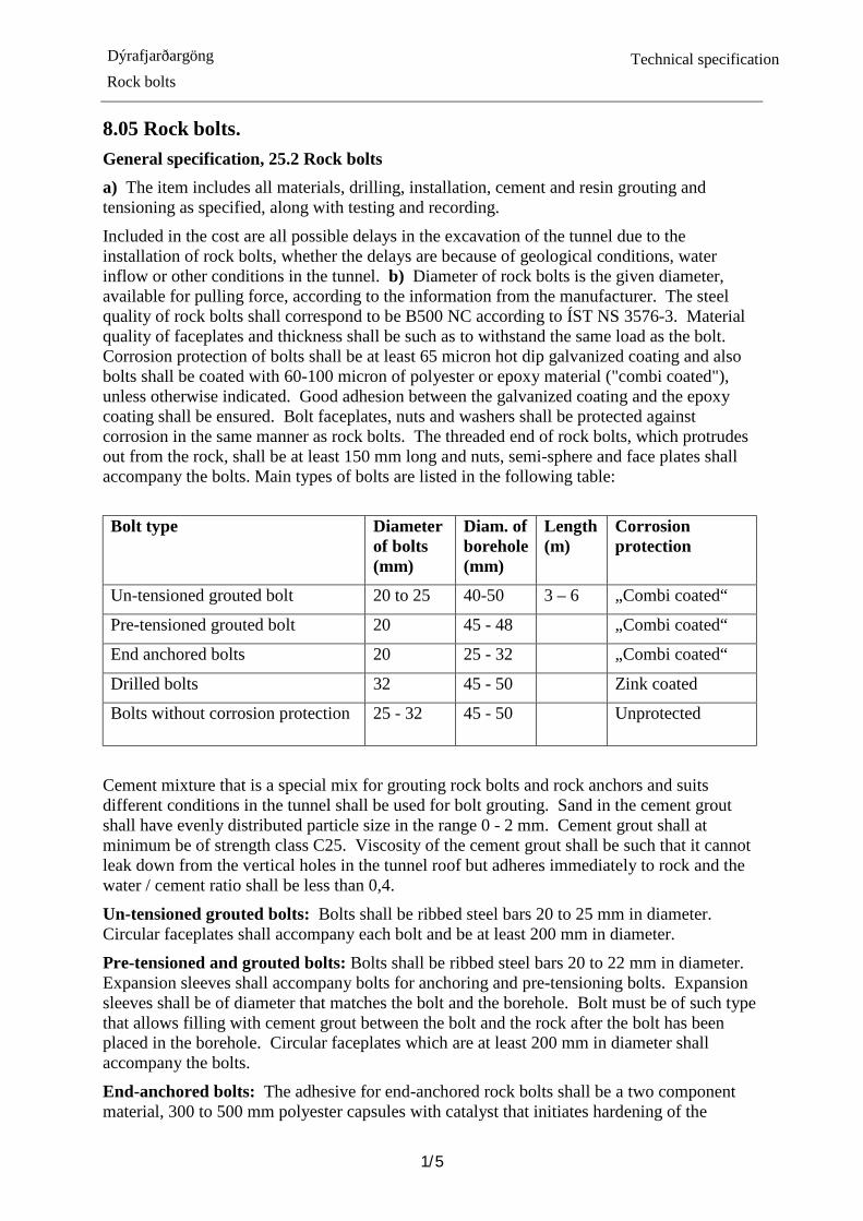
Included in the cost are all possible delays in the excavation of the tunnel due to the installation of rock bolts, whether the delays are because of geological conditions, water inflow or other conditions in the tunnel. b) Diameter of rock bolts is the given diameter, available for pulling force, according to the information from the manufacturer. The steel quality of rock bolts shall correspond to be B500 NC according to ÍST NS 3576-3. Material quality of faceplates and thickness shall be such as to withstand the same load as the bolt. Corrosion protection of bolts shall be at least 65 micron hot dip galvanized coating and also bolts shall be coated with 60-100 micron of polyester or epoxy material ("combi coated"), unless otherwise indicated. Good adhesion between the galvanized coating and the epoxy coating shall be ensured. Bolt faceplates, nuts and washers shall be protected against corrosion in the same manner as rock bolts. The threaded end of rock bolts, which protrudes out from the rock, shall be at least 150 mm long and nuts, semi-sphere and face plates shall accompany the bolts. Main types of bolts are listed in the following table:
Bolt type Diameter
of bolts (mm)
Diam. of borehole (mm)
Length (m)
Corrosion protection
Un-tensioned grouted bolt 20 to 25 40-50 3 – 6 „Combi coated“
Pre-tensioned grouted bolt 20 45 - 48 „Combi coated“
End anchored bolts 20 25 - 32 „Combi coated“
Drilled bolts 32 45 - 50 Zink coated
Bolts without corrosion protection 25 - 32 45 - 50 Unprotected
Cement mixture that is a special mix for grouting rock bolts and rock anchors and suits different conditions in the tunnel shall be used for bolt grouting. Sand in the cement grout shall have evenly distributed particle size in the range 0 - 2 mm. Cement grout shall at minimum be of strength class C25. Viscosity of the cement grout shall be such that it cannot leak down from the vertical holes in the tunnel roof but adheres immediately to rock and the water / cement ratio shall be less than 0,4.
Un-tensioned grouted bolts: Bolts shall be ribbed steel bars 20 to 25 mm in diameter. Circular faceplates shall accompany each bolt and be at least 200 mm in diameter.
Pre-tensioned and grouted bolts: Bolts shall be ribbed steel bars 20 to 22 mm in diameter. Expansion sleeves shall accompany bolts for anchoring and pre-tensioning bolts. Expansion sleeves shall be of diameter that matches the bolt and the borehole. Bolt must be of such type that allows filling with cement grout between the bolt and the rock after the bolt has been placed in the borehole. Circular faceplates which are at least 200 mm in diameter shall accompany the bolts.
End-anchored bolts: The adhesive for end-anchored rock bolts shall be a two component material, 300 to 500 mm polyester capsules with catalyst that initiates hardening of the

Dýrafjarðargöng Rock bolts
Technical specification
2/5
material when a bolt is pushed through the capsule and be specially designed for anchoring rock bolts. Faceplates shall be triangular and be at least 400 x 500 mm in size and the thickness of the faceplates shall be such as to withstand the same load as the bolts. End anchored bolts are not grouted.
Drilled bolts: Bolts shall be hollow drilling rods joined with drilling rod sleeves and with drill bit that allows bolts to be drilled directly into rock and be grouted afterwards. The outer diameter of the bolt shall be about 32 mm and inner diameter < 15 mm. Bolts shall be grouted with cement grout through hole in the rod (drill rod).
Bolts without corrosion protection: Bolts shall be 25 to 32 mm ribbed steel bars without faceplates. Bolts shall be grouted bolts unless the OR agrees otherwise.
c) Before rock bolting begins, the Contractor shall ensure that the cross section has been excavated to the design lines of the excavation. The decision on the type, length and location of rock bolts for rock support during the excavation phase shall be jointly made by the OR and the Contractor in view of the geological conditions. The same applies for rock bolting and length of rock bolts in the portal excavation before tunnelling begins.
Rock bolts shall be positioned so that they can be part of the permanent rock support of the tunnel. Generally, rock bolts shall be installed in each blasting round before a new one is blasted and never shall there be more than 15 m from the face unsupported without rock bolts. Where he deems necessary OR will at the end of the excavation phase decide on further rock bolting for permanent rock support of the tunnel.
Boreholes shall be cleaned with air and water just before bolt fasteners (cement grout, adhesive capsules or anchor sleeves) are installed in the hole.
Un-tensioned grouted bolts: Bolts shall generally be 3-4 m long ribbed steel bars. At the tunnel portals it is likely that longer grouted bolts are needed, 5-6 m long, to support the rock before excavation of tunnel commences. Bolts shall be grouted to the rock without voids along the whole length of the bolt. Therefore, it is a requirement that boreholes for un-tensioned grouted rock bolts are filled with cement grout from bottom up the hole and that the cement grout extrudes from the hole when a rock bolts has reached close to the bottom of the hole. The faceplates shall lie close to the rock / sprayed concrete and the nut, that holds the plate, shall be securely tightened after the grout has set.
Pre-tensioned grouted bolts: Bolts shall only be used where conditions require, for example, were short term stability of rock in the roof and walls of the tunnel is poor or where there is a lot of water in the boreholes. Bolts shall be pre-tensioned with end anchor and the pre-tension force shall be 50 kN. Bolts shall be grouted later with injection of cement grout that fills the entire void between the rock bolts and rock in the hole from bottom up the hole. No air voids shall be left in the hole. If rock is sprayed concrete before the grout injection, grouting holes in the faceplates/nut shall be protected so that the bolt can be grouted after the concrete spraying.
End-anchored bolts: Bolts shall only be used where high rock stresses exist, for example where the rock cover over the tunnel is thickness. The difference between the nominal diameter of bolt and diameter of borehole shall be between 5 to 15 mm. The rock bolt in the hole must be turned with a pneumatic drill to achieve perfect mixing of the adhesive components in the capsules Rock bolts shall be tensioned by tightening the nut to the bolt plate. The loading force shall be 50 kN.
Drilled bolts: Use of this type of rock bolt is not anticipated unless the tunnel intersects a very bad rock and rock bolting with other types of bolts cannot be achieved. Borehole
Dýrafjarðargöng Rock bolts
Technical specification
3/5
diameter shall be between 45 to 60 mm. Bolts shall be grouted after installation with injection of cement grout through the hollow bolt so that the grout fills all voids between the rock bolt and the rock in the hole from the bottom up the hole.
Bolts without corrosion protection: The bolts may be used for spiling bolting beyond the face, e.g. where the blasting rounds needs to be shortened and sprayed concrete reinforce ribs are installed in the tunnel due to unstable rock. These bolts are either not grouted or grouted in the same way as un-tensioned grouted bolts.Based on circumstances different types of bolts may be used for spiling bolting, pending approval of the OR. Spiling bolts shall be drilled with 10-25°angle to the tunnel alignment and bolts shall be grouted unless approved otherwise the OR.
d) The Contractor shall seek approval from the OR for type of rock bolts with accompanied materials, which he intends to use in the tunnelling, and submit data from the manufacturer of the rock bolts to verify their quality. To verify anchorage ofbolts 2% of the installed bolts, of each type, shall be tested in pull out testing with a pull force that is 80% of the yield strength of the bolt.
The Contractor shall record the use of bolts daily. The record shall indicate where and how many bolts were used, what type of bolts were used and when bolting began and ended.
Item 43 25.232 End-anchored rock-bolts, D=20 mm, L= 2,4 m a) The work item includes all materials, drilling, installation, anchoring with resin grout as specified. Included in the unit price are i.a. resin capsules, faceplates, half-spheres, nuts, testing and recording. Included in the cost are all delays in the excavation of the tunnel because of installation of rock bolts, whether the delays are because of geological conditions, water inflow or other conditions in the tunnel.
f) The payment is based on the number of fully installed rock bolts as specified.
There will be no payment for rock bolts that are needed for supporting unnecessary overbreak in the tunnel, nor for temporary rock bolting needed for the Contractors own work, nor for rock bolts that are installed in places where they are useless for rock supporting, in the opinion of the OR. Unit: pcs
Item 44 25.246 Drilled bolts, D= 32 mm, L= 6 m Item 45 25.248 Drilled bolts, D= 32 mm, L= 8 m a) The work item includes all materials, drilling work, installation and grouting as specified. Included are i.a. drill bit. faceplates, hemispherical washer and nuts, testing and recording. Included in the cost are all delays that may occur in the excavation of tunnel because of installation of rock bolts, whether the delays are because of geological conditions, water inflow or other conditions in the tunnel. f) The payment is based on the number of fully installed drilled rock bolts as specified.
There will be no payment for rock bolts that are needed for supporting unnecessary overbreak in the tunnel, nor for temporary rock bolting needed for the Contractors own work, nor for rock bolts that are installed in places where they are useless for rock supporting, in the opinion of the OR.
Unit: pcs

Dýrafjarðargöng Rock bolts
Technical specification
4/5
Item 46 25.2561 Bolts without corrosion protection, grouted, D= 32mm, L= 6 m Item 47 25.2562 Bolts without corrosion protection, grouted, D= 32mm, L= 8 m a) The work item includes all materials and work for drilling, installation, grouting, testing and recording as specified. Included are i.a. cement grout, testing and recording. Included in the cost are all possible delays in the excavation of the tunnel because of installation of rock bolts, whether delays are because of geological conditions, water inflow or other conditions in the tunnel.
c) Bolts are to be grouted with cement grout.
f) The payment is based on the number of fully installed rock-bolts as specified.
Unit: pcs
Item 48 25.2581 Bolts without corrosion protection, un-grouted, D= 32mm, L= 6 m Item 49 25.2582 Bolts without corrosion protection, un-grouted, D= 32mm, L= 8 m a) The work item includes all materials and work for drilling, installation, testing and recording as specified. Included are i.a. testing and recording. Included in the cost are all possible delays in the excavation of the tunnel because of installation of rock bolts, whether delays are because of geological conditions, water inflow or other conditions in the tunnel.
c) Bolts are not grouted in holes.
f) The payment is based on the number of fully installed rock-bolts as specified.
Unit: pcs
Item 50 25.273 Rockbolts at the face, D= 20mm, L= 3 m Item 51 25.274 Rockbolts at the face, D= 20mm, L= 4 m Item 52 25.275 Rockbolts at the face, D= 25mm, L= 5 m Item 53 25.276 Rockbolts at the face, D= 25mm, L= 6 m a) The work item includes all materials, drilling, installation and grouting of rock bolts up to 15 m from the tunnel face, whether bolts are un-tensioned grouted or tensioned grouted, as specified, i.a. end anchors, cement grout, faceplates, half spheres, nuts, testing and recording. Included in the unit prices shall be possible difficulties and delays that can arise when rock supporting the tunnel, whether delays or difficulties are because of poor geological conditions, water inflow or other conditions at the site.
c) It is in general the Contractors decision which type of bolt is used, but in general end-anchored grouted rockbolts shall be assumed.
f) The payment is based on the number of fully installed rock bolts as specified.
There will be no payment for rock bolts that are needed for supporting unnecessary overbreak in the tunnel, nor for temporary rock bolting needed for the Contractors own work, nor for rock bolts that are installed in places where they are useless for rock supporting, in the opinion of the OR.
Unit: pcs
Dýrafjarðargöng Rock bolts
Technical specification
5/5
Item 54 25.283 Rockbolts at the face, D= 20mm, L= 3 m Item 55 25.284 Rockbolts at the face, D= 20mm, L= 4 m Item 56 25.285 Rockbolts at the face, D= 25mm, L= 5 m Item 57 25.286 Rockbolts at the face, D= 25mm, L= 6 m a) The work item includes all materials, drilling, installation and grouting of rock bolts more than 15 m from the tunnel face, whether bolts are un-tensioned grouted or tensioned grouted, as specified, i.a. end anchors, cement grout, faceplates, half spheres, nuts, testing and recording.
Included in the unit prices shall be possible difficulties and delays that can arise when rock supporting the tunnel, whether delays or difficulties are because of poor geological conditions, water inflow or other conditions at the site.
c) It is in general the Contractors decision which type of bolt is used, but in general un-tensioned grouted rockbolts shall be assumed.
f) The payment is based on the number of fully installed rock bolts as specified.
There will be no payment for rock bolts that are needed for supporting unnecessary overbreak in the tunnel, nor for temporary rock bolting needed for the Contractors own work, nor for rock bolts that are installed in places where they are useless for rock supporting, in the opinion of the OR.
Unit: pcs
Item 58 25.3 Steel ties a) The work item includes all materials and work on installation of steel ties with all pertinent parts and fasteners and recording as specified.
Included in the cost are all possible delays in the excavation of the tunnel because of installation of steel ties, whether the delays are because of geological conditions, water inflow or other conditions in the tunnel.
b) Steel ties shall be composed of two interwoven or connected 10 mm ribbed steel bars.
Steel ties shall be protected against corrosion in the same manner as rock bolts, see 25.2.. Steel quality shall be B500 C.
c) Steel ties shall be placed between bolts and linked together as specified. For that it shall be tried to locate the rock bolts such that steel ties between the rock bolts lies almost everywhere tight to the rock.
Steel ties shall always be covered with sprayed concrete.
f) The payment is based on the meter of length of fully installed steel ties as specified.
Units: m.

Dýrafjarðargöng Sprayed concrete
Technical specification
1
8.06 Sprayed concrete General Specification 25.4 Sprayed concrete a) The item includes all materials and work with sprayed concrete, including all costs of processing and transport of concrete materials on site, admixtures, production of concrete, transport of concrete to the site, cleaning surfaces, spraying concrete, recording, protection against precipitation, frost and dehydration during transportation, spraying and curing, testing and thickness measurement of concrete and recording.
b) Sprayed concrete shall be in accordance with the Standards ÍST EN 14487-1 Sprayed Concrete - Part 1: Definitions, specifications and conformity and ÍST EN 14487-2 Sprayed concrete - Part 2: Execution, and as specified in this specification.
Following there are standards that apply to sprayed concrete, where relevant, and referred to at appropriate places in the text. If the publication year of the standard is specified that issue shall be followed, else the latest version and its annexes shall apply. ÍST EN 197-1 Cement - Part 1: Composition, specifications and conformity criteria for
common cement. ÍST-EN 206-1 Concrete - Part 1: Specifications, performance, production and conformity
ÍST EN 932-3 Test for general properties of aggregates - Part 3: Procedure and terminology for simplified petrographic description. -
ÍST EN 933-1 Tests for geometrical properties of aggregates, Part 1: Determination of particle size distribution - Sieving method.
ÍST EN 934-1 Admixtures for concrete, mortar and grout, - Part 1 Common requirements ÍST-EN 934-2 Admixtures for concrete, mortar and grout - Part 2: Concrete admixtures -
Definitions, requirements, conformity, marking and labelling ÍST EN 934-5 Admixtures for concrete, mortar and grout - Part 5: Admixtures for use in
sprayed concrete - Definitions, requirements, conformity, marking and labelling
ÍST EN 934-6 Admixtures for concrete, mortar, and grout - Part 6: Sampling, conformity control and evaluation of conformity.
ÍST-EN 1097-6 Tests for mechanical and physical properties of aggregates - Part 6: Determination of particle density and water absorption.
ÍST EN 12504-1 Testing concrete in structures - Part 1: Cored specimens - Taking, examining and testing in compression.
ÍST EN 12620 Aggregates for concrete ÍST EN 13263-1 Silica fume for concrete -Part 1: Definitions, requirements and conformity
criteria. ÍST EN 13791 Assessment of in-situ compressive strength in structures and precast concrete
components. ÍST EN 14487-1 Sprayed concrete – Part 1: Definitions, specifications and conformity.
ÍST EN 14487-2 Sprayed concrete – Part 2: Execution.
ÍST EN 14488-1 Testing sprayed concrete – Part 1: Sampling fresh and hardened concrete. ÍST EN 14488-2 Testing sprayed concrete - Part 2: Compressive strength of young sprayed
concrete.
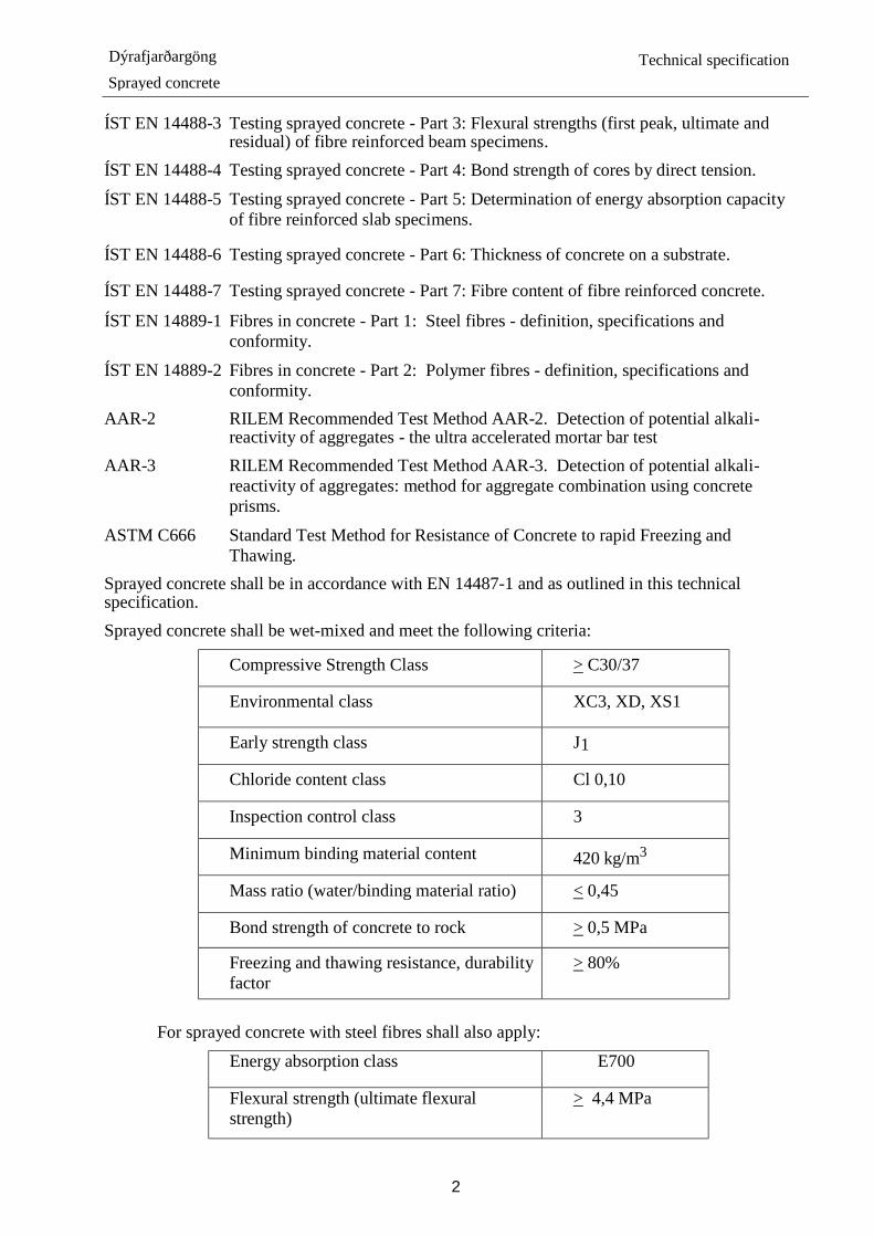
Dýrafjarðargöng Sprayed concrete
Technical specification
2
ÍST EN 14488-3 Testing sprayed concrete - Part 3: Flexural strengths (first peak, ultimate and residual) of fibre reinforced beam specimens.
ÍST EN 14488-4 Testing sprayed concrete - Part 4: Bond strength of cores by direct tension.
ÍST EN 14488-5 Testing sprayed concrete - Part 5: Determination of energy absorption capacity of fibre reinforced slab specimens.
ÍST EN 14488-6 Testing sprayed concrete - Part 6: Thickness of concrete on a substrate.
ÍST EN 14488-7 Testing sprayed concrete - Part 7: Fibre content of fibre reinforced concrete.
ÍST EN 14889-1 Fibres in concrete - Part 1: Steel fibres - definition, specifications and conformity.
ÍST EN 14889-2 Fibres in concrete - Part 2: Polymer fibres - definition, specifications and conformity.
AAR-2 RILEM Recommended Test Method AAR-2. Detection of potential alkali-reactivity of aggregates - the ultra accelerated mortar bar test
AAR-3 RILEM Recommended Test Method AAR-3. Detection of potential alkali-reactivity of aggregates: method for aggregate combination using concrete prisms.
ASTM C666 Standard Test Method for Resistance of Concrete to rapid Freezing and Thawing.
Sprayed concrete shall be in accordance with EN 14487-1 and as outlined in this technical specification. Sprayed concrete shall be wet-mixed and meet the following criteria:
Compressive Strength Class > C30/37
Environmental class XC3, XD, XS1
Early strength class J1
Chloride content class Cl 0,10
Inspection control class 3
Minimum binding material content 420 kg/m3
Mass ratio (water/binding material ratio) < 0,45
Bond strength of concrete to rock > 0,5 MPa
Freezing and thawing resistance, durability factor
> 80%
For sprayed concrete with steel fibres shall also apply:
Energy absorption class E700
Flexural strength (ultimate flexural strength)
> 4,4 MPa

Dýrafjarðargöng Sprayed concrete
Technical specification
3
When calculating the water cement ratio of concrete mixture effective water content shall be used which is the total water content in the mixture minus saturated water content in aggregates. The total water content consists of the blending water, moisture in aggregates, water in admixtures, and additives, etc. Constituent materials in sprayed concrete shall be in accordance with EN 14487-1, 5.1 as specified in this technical specification. Cement: Cement in sprayed concrete shall be in: accordance with ÍST EN 197-1 and shall comply with other requirements for sprayed concrete and conditions on site. Strength category shall be 42.5R or higher. Cement type is subject to the approval of the OR. Additives: Additives shall be in accordance with relevant standards. In sprayed concrete there shall be used a minimum of 6 % silica fume of cement weight and not more than 10 %. Here meaning the total quantity of silica fume in concrete mix including the silica fume that might be already in the cement. The use of other additives is subject to the approval of the Engineer. Further see in ÍST EN 206-1. Aggregates: Aggregates shall be in accordance with EN 12620 and as further specified here:
Properties: Class
Particle size distribution GNG90 Sieve limits, see below
Content of fines f10
Freezing and thawing resistance F1 Further there shall be available testing results on particle density, water absorption, chloride content, humus content, petrographic analyses. Particle size distribution of aggregates shall be within limits in following table.
Mesh size Percentage passing
(mm) (%)
11.2 100
8.0 90 - 100
4.0 73 - 100
2.0 55 - 90
1.0 37 - 72
0.50 22 - 50
0.25 11 - 26
0.125 2.5 - 12 Alkali reaction: Sprayed concrete shall be non-reactive to alkali-silicate reactions and the Contractor shall prove this with relevant tests. If aggregates prove to be non-reactive, i.e. expansion is less than 0,20% after 14 days according to testing after RILEM method AAR-2, no further alkali reaction tests are required. Sprayed concrete which contains alkali-reactive aggregates is considered non-reactive if either one of the following criteria is met:

Dýrafjarðargöng Sprayed concrete
Technical specification
4
i) Expansion of mortar prisms made from the mixture of aggregates, cement and additives intended for use by the Contractor, is less than 0,20% after 14 days according to RILEM method AAR-2.
ii) Expansion of the mortar prisms is less than 0,05 % after 12 months according to RILEM method AAR-3.
If expansion according to item i) is more than 0.20% but less than 0,30% the OR may temporarily approve the use of the concrete mix until results according to the AAR-3 testing method are available. Admixtures: Admixtures shall be in accordance with IST EN 934 and shall comply with other requirements for sprayed concrete and conditions on site. Compatibility of admixtures with other materials of the sprayed concrete mixture, as well as with the mixing process itself, shall be verified. Use of admixtures shall be in accordance with the manufacturer's guidelines.
Admixture added to the concrete during spraying shall be alkali free admixtures
c) Equipment, concrete mixing and delivery shall be in accordance with ÍST EN 14487-2, Article 7 and Article 8 and further as described in this specification and concrete spaying shall be in accordance with Article 9. Work support: Sprayed concrete to secure work surroundings. Normally during the tunnel excavation phase, at the tunnel face and two to five blast rounds behind the face. Use of sprayed concrete for work support shall be taken jointly determined by the Contractor and the OR. Work support with sprayed concrete shall follow the tunnel excavation to secure safety and the stability of the rock and be part of the permanent rock support of the tunnel as possible. Unsupported rock in roof of the tunnel shall never exceed 15 m from the tunnel face.
Concrete spraying on the tunnel walls, during the excavation phase, shall be as little as possible and as geological condition allows.
Final support: Sprayed concrete for permanent rock support of tunnel. Normally after tunnel excavation is finished or well behind the tunnel face. The OR will determine and specify the thickness of the sprayed concrete layer for permanent rock support of the tunnel.
Final support or permanent support is usually done simultaneously as pipes, cables and various other devices, that accompanied the excavation of tunnel, are removed. Complete rock support of the tunnel roof, parallel with tunnel excavation, can be considered where the rock conditions are good. Then thickness of the sprayed concrete layer shall never be less than specified thickness. To achieve specified thickness concrete spraying shall take place at least two rounds behind the face.
Final support of the tunnel walls shall be performed after excavation of tunnel is completed.
Sprayed concrete may be of different thickness in the roof and walls of a tunnel according to the specifications given by the OR and every thickness interval can be variable along the length of the tunnel, but generally not less than 5 m in length (length of one round).
Minimum thickness at completion of rock support, work support and final support in total, shall be 60 mm on walls and 80 mm in roof of the tunnel. Working procedure: The Contractor shall always have available on stock sufficient amount of approved aggregates at the concrete batch plant. All handling and storage of aggregates shall be such that the quality is maintained and mixing of foreign materials that might clog the spraying equipment, shall be prevented. After material is approved and placed in storage, the Contractor shall not use it for other purposes without approval of the OR. In aggregate production,

Dýrafjarðargöng Sprayed concrete
Technical specification
5
production control shall be applied, in accordance with ÍST EN 12620, Annex H.
Generally accepted methods for spayed concrete application shall be used and skilled workers with special training in concrete spraying shall perform the work. The Contractor shall have available and use sprayed concrete equipment and devises, with which he can use to spray on the face of the tunnel before mucking starts, if necessary. Use of chemicals that speed setting and hardening of the sprayed concrete and chemicals that has a negative influence on other sprayed concrete properties shall always be minimal and the sprayed concrete robot shall be fitted with devices to control use of such materials.
Before application of sprayed concrete starts all loose material from the rock surface shall be cleaned with a air-water jet, with at least 0.7 MPa pressure, where the volume of air is at least 10 m3/mín and water flow is at least 300 l / min. The distance from nozzle to face shall be less than 1.5 m. Cleaning of rock surfaces shall start at the top of the tunnel cross section and the rock shall be cleaned down the walls to the tunnel floor. It is of particular importance that the walls are cleaned well below the surface where sprayed concrete shall be applied. In addition to dust, it is important to thoroughly clean all oil and soot from engine exhaust and clay from surfaces of rock and fractures. If necessary, a grease solvent shall be used to remove oil and soot from rock surfaces. The OR shall approve the cleaning of rock surfaces before sprayed concrete application begins. The cleaning water shall have drained from the rock surface and the surface temperature must be more than 2 °C when applying sprayed concrete. If a second layer is sprayed onto an older concrete surface special care shall be taken that the surface of the first layer is moist and clean in accordance with the cleaning requirements for rock surfaces to be sprayed concreted. Spraying shall be perpendicular to the surface with even flow of concrete where the nozzle is kept within 1.5 m from the surface. Spraying shall be from bottom up so as not to spray over rebound from spraying. Care shall be taken that the entire surface of the rock is covered with sprayed concrete, especially surfaces facing away from the sprayer to avoid thin spots or gaps in the concrete layer.
Temperature of the concrete shall be between 15 to 30°C when spraying starts and temperature of the accelerator shall not be less than temperature of the concrete.
Spraying shall be such that neither thick humps forms (or too thick layers), so that there is risk of concrete subsidence or a fall of the wall, nor too thin layers that breaks up at little loads and will thus not be of use as part of the final support of the tunnel.
It shall be expected that the total thickness of the spayed concrete in places can be over 180 mm, sprayed in several layers. Common thickness of spayed concrete is estimated 60 to 100 mm. If sprayed concrete is applied in several layers each layer shall not be less than 30 mm.
Welded wire mesh, steel ties and rock bolts shall be covered by a minimum of 30 mm thick layer of sprayed concrete or as specified. Concrete that has not been sprayed within 1,5 hours after it was produced shall be discarded and new concrete mixed. There will no payment for discarded concrete. If there is much water inflow through fissures in the rock, special types of admixtures may be used or increased amount of admixtures, such as admixtures to increase cohesion and adhesion, rapid setting and hardening of the sprayed concrete. Change in use of admixtures is pending the OR approval in each case.
The Contractor shall clean and remove all rebound of sprayed concrete. Use of rebound for sprayed concrete production is always prohibited. The Contractor shall at his own expense repair sprayed concrete that has been damaged by Contractors working methods or carelessness.

Dýrafjarðargöng Sprayed concrete
Technical specification
6
Curing and protection of sprayed concrete shall begin as soon as possible after spraying. To prevent drying out of the concrete curing compound shall be mixed to the concrete before spraying for internal curing. It is not permitted to use curing compound to prevent dehydration of a surface where an added layer is to be sprayed. vThe surface temperature of sprayed concrete shall be kept higher than 3°C and it shall be protected from frost until the compressive strength has reached a minimum of 5 MPa.
d) The OR shall approve materials, equipment and working procedures which the Contractor intends to use given he has presented technical information which show that material, equipment, and procedures fulfil requirements. Among others the Contractor shall submit a detailed execution document describing his working procedure, according to ÍST EN 14487-2 and submit this to review and approval. In the execution document i.a. planned materials and machinery, methodology, manpower, recording, conformity control and tests shall be described.
At the place of concrete production there shall be a documented production control system (production control manual) according to ÍST EN 206-1, Article 9, and in accordance with ÍST EN 14487-1, Article 7.4.
Inspection and monitoring shall be in accordance with ÍST EN 14487-2, article 11, control class 3 and the Contractor shall carry out necessary checks and tests to ensure full compliance with the specification and other project data.
The Contractor shall on a daily basis when applying sprayed concrete submit a report on the use of the concrete. The report shall include detailed information on to composition of the concrete, when, where and how much of the concrete was used in each sprayed concrete application.
At the end of each week, report on the production of sprayed concrete, sampling and sampling places and test results shall be submitted to the OR, but these will be evaluated when approving payments to the Contractor.
After sprayed concrete is applied the Contractor shall scan the tunnel with acceptable density of measuring points to be able to prove that the tunnel is everywhere outside the design line. The Contractor shall also compare scanned surface before and after spraying concrete to evaluate if thickness of sprayed concrete is in accordance with specification. Difference deviation of before and after spraying concrete shall be shown on flattened map, c.f. d) in chapter 22.5 Tunnel excavation. Preconstruction tests: Preconstruction testing of aggregate shall be done in accordance with ÍST EN 12620, Article 7 and Annex H. Preconstruction testing of sprayed concrete shall be conducted according to ÍST EN 14487-1, Article 7.3. Preconstruction testing shall at least cover the properties of sprayed concrete as specified in paragraph b above. Alkali reaction of the aggregate shall be tested with the RILEM-method AAR-2. If the aggregate proves to be reactive and the Contractor desires to use it nevertheless, then the alkali reactivity of a mixture of aggregates, cement and additives, which the contractor intends to use, shall be tested according to RILEM – method AAR-2 and method AAR-3.
Conformity tests: Production control an aggregate shall be conducted according to tables H.1 to H.3 in ÍST EN12620 - Annex H
Conformity control shall be in accordance with ÍST EN 14487-1, Article 7.4. Minimum frequency of tests on concrete mix shall be according to Table 11 in that standard and testing of sprayed concrete according to Table 12 with the following modifications.

Dýrafjarðargöng Sprayed concrete
Technical specification
7
Testing Fresh concrete: Water / cement ratio Quantity of accelerators Quantity of fibres*
Testing according to Calculated Measured ÍST EN 14488-7
Frequency of testing Each mixture Each spraying 1 /100 m³
Hardened concrete: Concrete early strength ÍST EN 14488-2 1/250 m³ Compressive strength ÍST EN 12504-1 1/250 m³ Density of hardened concrete ÍST EN 12390-7 Same samples as for compressive test
Bond strength knocking With < 50 m intervals in roof and both walls
Energy absorption* ÍST EN 14488-5 1/400 m³ Fibre content of hardened concrete* ÍST EN 14488-7 Same samples as tested for energy
absorption Flexural strength* ÍST EN 14488-3 1/400 m³ Freezing/thawing resistance ASTM C666 1/5000 m3 Thickness measurements ÍST EN 14488-6 With ≤ 50 m intervals in roof and on
both walls. *Only tested on concrete with fibre.
Conformity criteria for concrete shall be according to ÍST EN 14487-1, Article 7.5. Evaluation of compressive strength class of drilled cores shall be in accordance with ÍST EN 13791. To check concrete bond to rock knocking shall be applied to roof and walls to map hollow sound. Roof and wall shall be mapped with minimum 50 m interval, minimum 1 knock/3m2, with hammer or scaling stick, over 10 m2 area on each wall and in roof. Where hollow sound is found size of the area shall be mapped in more detail. Concrete shall be between 7-28 days old when inspection is carried out. Results shall be recorded on prepared sheets, that are approved by the OR. Fibre quantity in newly sprayed concrete shall be measured for the same mix that samples are taken for energy absorption tests. Samples shall be taken immediately after spraying and tested before it hardens. Thickness of sprayed concrete shall be measured according to ÍST EN 14488-6. Tunnel surfaces, i.e. the right wall, ceiling and left wall, shall be checked and the length of each surface can be a maximum of 50 m, but can be much less. Thickness of sprayed concrete shall always be measured when there will be a change in thickness specified. Three 5-point stars shall be measured on every surface. The OR determines the location of these stars. If a measurement on a surface does not meet the thickness requirements, the Contractor, if he so wishes, can split the surface in question into smaller surfaces and measure three stars in these smaller surfaces and then the same conditions apply as before for each of the new surfaces. Rebound shall be measured if required and the Contractor shall have available the appropriate tools to measure rebound. The OR will decide whether the measurement holes in the sprayed concrete shall be backfilled.
If tests show that hardened sprayed concrete does not meet requirements as specified it will normally not be paid. This applies if the faultiness is caused by incorrect mixture or poor
Dýrafjarðargöng Sprayed concrete
Technical specification
8
workmanship, but not by adverse geological conditions.
All test results that the Contractor gets done and submits as a proof of quality of the concrete are considered the property of the Owner.
e) The average thickness shall be equal to or greater than the specified thickness. Minimum thickness shall be greater than 75% of thickness specified. Area is considered fully sprayed concreted if no thickness measurement star has an average thickness of less than 75% of the specified thickness and the average of three-stars is equal to or more than the specified thickness. If either condition is not met, a layer shall be added to the whole area according to instructions. The Contractor can however, if he so wishes, split the area in question in smaller areas and measure three stars in each area and then the same conditions apply as before for each of the new areas. Roughness is defined as the proportion between a tape measure length which follows the rock surface and another line of measure in the direction of tunnel and touches the outermost protrusions at the same location. The roughness shall be measured by three parallel lines, at least 4 m long, distributed on the area in question, in that section of the tunnel which roughness is to be evaluated. The average of those three lines is considered to be the roughness of the area at that location.
Item 59 25.433 Sprayed concrete on rock, 60 mm Item 60 25.434 Sprayed concrete on rock, 80 mm Item 61 25.435 Sprayed concrete on rock, 100 mm Item 62 25.436 Sprayed concrete on rock, 120 mm Item 63 25.437 Sprayed concrete on rock, 150 mm Item 64 25.438 Sprayed concrete on rock, 180 mm a) The work item includes all materials and work with sprayed concrete for work support as well as final support as specified. Included are i.a. aggregates, admixtures, mixing, transport, surface cleaning of surfaces, spraying, curing, testing, thickness measurement and recording. Included are also the difficulties and delays that can arise because of tunnel support, whether delays or difficulties are resulting from poor geological conditions, water inflow or other conditions at site.
c) Roughness of the rock must be taken into consideration when estimating quantity of sprayed concrete. Included in unit prices shall be the amount of concrete required to achieve the required average thickness for roughness ≤ 1.4 and over-excavation. The Contractor can claim for an extra payment if measured roughness, as defined in 25.4 e), is > 1.4
f) Payment is based on specified area of spayed concrete that has been sprayed on rock in the tunnel. The amount shall be determined by calculations based on the design lines for excavation in roof and the walls of the tunnel, 0.3 m below the surface of road shoulders, as further specified by the OR. The payment is based on specified layer thickness for permanent support of the tunnel, which is the combined thickness of sprayed concrete layer for work- and final support. Payment for work support is partial payment for total support layer at specified location. Sprayed concrete needed to support unnecessary overbreak in the tunnel resulting from bad workmanship, will not be paid. In the Bill of Quantities 6 thickness classes are specified 60, 80, 100, 120, 150, 180 mm. If another thickness is specified calculated price shall be in accordance with relative difference

Dýrafjarðargöng Sprayed concrete
Technical specification
9
in the Contractor´s unit prices for different thicknesses. Thus, the unit price for a 50 mm concrete layer shall be 5/6 of unit price for 60 mm concrete layers in tendered BoQ. For 240 mm sprayed concrete layer the unit price shall be the unit price for 180 mm sprayed concrete layer plus the difference between the unit prices of 120 and 180 mm concrete layers etc. Unit: m2. Item 65 25.44 Sprayed concrete on rock under special conditions a) The work item includes all materials and work with sprayed concrete where there is geological over-break and area-payment cannot be applied and for reinforced sprayed concrete ribs, as specified. Included are i.a. aggregate, admixtures, mixing, transport, surface cleaning, spraying, curing, testing and recording. Included are also the difficulties and delays that can arise because of tunnel rock support, whether delays or difficulties are resulting from poor geological conditions, water inflow or other conditions at site. c) Geological over-break shall be concrete sprayed as specified by the OR. Thickness and texture shall be as even as possible. Sprayed concrete reinforced ribs shall be as shown on the drawings unless otherwise approved by the OR. In general, a layer of sprayed concrete shall be placed for levelling under the ribs. f) Payment is based on the cubic meter of mixed sprayed concrete from the concrete batch plant, which is sprayed on rock. Rebound exceeding 10% and unused sprayed concrete shall be deducted from the mixed quantity. Sprayed concrete needed to support unnecessary overbreak in the tunnel resulting from bad workmanship, will not be paid. Unit: m3.
General specification 25.45 Sprayed concrete on waterproof lining a) The work item includes all materials and work with sprayed concrete on waterproof lining, either the first or the second layer as specified. Included are i.a. aggregates, admixtures, mixing, transportation, surface cleaning, spraying, curing, removing rebound, testing, thickness measurement, and recording.
c) As a fire protection all waterproof linings shall be covered with 60 to 80 mm thick sprayed concrete. 60 mm layer is without mesh reinforcement and is applied in two layers. The first layer shall be 40 mm thick, with reinforcement fibres (E700) and 2 kg /m³ of polymer fibre to increase fire resistance, and the second layer should be 20 mm by 2 kg /m³ of polymer fibre to increase fire resistance. If welded wire mesh is placed over lining the sprayed concrete layer shall be 80 mm, with only 2 kg/m³ of polymer fibre to increase fire resistance. The sprayed concrete layer shall be applied in two or more steps.
Before spraying begins installations and belonging fixture shall be protected where needed. Rebound shall be removed.
To ensure an even concrete thickness layer while spraying, the thickness of the sprayed concrete shall be measured by inserting a pin through the wet concrete or use a thickness pins, fastened in the lining as specified.

Dýrafjarðargöng Sprayed concrete
Technical specification
10
d) After spraying the concrete, holes shall be drilled through the layer for layer thickness measurements. The grid of the measurement points shall be in accordance with EN ÍST 14488-6. Each lining area shall be inspected separately and divided into sections where there are total linings and the thickness measure in the same way as for the sprayed concrete for rock support. On lining surfaces <40m2 it is sufficient to measure one star. e) The average thickness of sprayed concrete shall be at least as specified and the deviation must not exceed -10 mm / +30 mm from the specified total thickness. Thickness is defined as the average measurements of a 5-point star. Measured the minimum thickness is the lowest average measurements of a 5-point star. The maximum thickness is defined accordingly. If the thickness proves insufficient, addition shall be placed on the entire surface, however, the Contractor can divide surfaces into sub-surfaces and measure tree stars in each surface.
Item 66 25.451 Sprayed concrete on waterproof lining, 20 mm Item 67 25.452 Sprayed concrete on waterproof lining, 40 mm Item 68 25.454 Sprayed concrete on waterproof lining, 80 mm a) The work item includes all materials and work with sprayed concrete on waterproof lining, either the first or the second layer as specified. Included are i.a. aggregates, admixtures, mixing, transportation, surface cleaning, spraying, curing, removing rebound, testing, thickness measurement, and recording.
c) 80 mm layer shall be applied in two or more layers. f) Payment is for linings installed based on specified design area plus 0,3 m wide edge on along the linings (but not bottom edge) for closure.
Units: m2
General specification 25.5 Fibres a) The work item includes all materials, work and cost of using fibres in sprayed concrete in accordance with the specifications. Included are i.a. testing and recording and possible difficulties and delays that may arise. b) Steel fibres shall be in accordance with following standards: ÍST EN 14889-1. Part 1: Steel fibres – Definitions. Specifications and conformity ÍST EN 14889-2. Part 2: Polymer fibres – Definitions. Specifications and conformity Reinforcement fibres: When using fibres to increase strength of sprayed concrete (energy absorption, bending strength) shall:
− Steel fibres be in accordance with EN 14889-1 group I, cold-drawn wire, deformed. Steel fibres shall be at least 30 mm long, 0.5 mm thick and the ratio length/diameter ≥ 60. Tensile strength of steel fibre, Rm, shall be higher than 1000 MPa,
− polymer fibres be in accordance with ÍST EN 1889-2, group II macro fibres. To meet requirements of minimum 700 J energy absorption for sprayed concrete with fibres the amount of steel fibres shall be 30-40 kg/m3, measured in sprayed concrete, but amount of polymer fibres shall be 4,5-5,5 kg/m3, measured in sprayed concrete. Required amount depends on strength requirements and type of fibres and shall be determined in pretesting. Fibres to increase fire resistance: When using fibres to meet requirements on fire resistance of

Dýrafjarðargöng Sprayed concrete
Technical specification
11
concrete, fibres shall be
− polymer fibres in accordance with ÍST EN 14889-2, group Ia monofilament fibre, handled specifically to minimize cohesiveness of fibres and water in the mixing. For monofilament polypropylene fibres, that are 18 μm in diameter and 6 mm long, 2 kg/m3 is needed to meet fire resistance requirements. The fibres must be The amount of fibre of this type shall be 2 kg/m3, measured in sprayed concrete.
The OR can approve other types of polymer fibres, if it is demonstrated that the type and the specified quantity is equal or better for the fire resistance of the concrete.
c) The type and quantity of fibres shall be used as specified by the OR.
It is generally not expected to use the reinforcement fibres, where reinforcement steel, steel bars or welded wire mesh, is used.
It shall be ensured that the fibres mix well with the concrete and do not form lumps. d) Data from the fibre manufacturer shall be submitted to the OR for approval prior to use, showing that the type and properties of the fibres are in accordance with the above standards. The following information shall be stipulated. Steel fibres: length, equivalent diameter, ratio length/diameter, tension strength, E-modulus and other that might be requested. Reinforcement polymer fibres: material type, shape, surface handling, length, ratio length/equivalent diameter, tension strength, E-modulus, melting limit, ignition limit and other that might be requested. Fire safety polymer fibres: material type, shape, type of bundles if so, surface handling, length, ratio length/equivalent diameter, melting limit, ignition limit and other that might be requested. Type of reinforcement fibres and quantity to meet requirements for energy absorption shall be verified with preconstruction tests. Other types of steel fibres shall not be used unless tested in preconstruction tests which show that the type and quantity of fibres meet the requirements for energy absorption. Conformity requirements for the quantity of fibres shall be according to IST EN 14487-1 article 7.5.2.1. Samples shall be taken after spraying concrete on walls or roof. Sampling and testing shall be according to ÍST EN 14488-7. Three test coupons are considered one sample. Requirements are considered fulfilled if the result of sample test deviates less than 15 % of prescribed requirement. If requirements are not fulfilled three additive samples may be taken and average taken from all 6 test coupons. The test shall apply for all sprayed concrete of the same type since last test. e) The deviation in the amount of fibre measured in sprayed concrete, shall not be more than 15% of the prescribed quantity based on average of three test coupons.
Item 69 25.512 Polymer fibres a) The work item includes all materials, work and cost of using polymer fibres in sprayed concrete in accordance with the specifications. Included is i.a. testing and recording and possible problems or delays associated with the use of fibres.
c) OR can approve use of steel fibres instead of polymer macro fibres upon the Contractors request if requirements on energy absorption are met. Then kilogram price of steel fibres shall not be higher than 1/8 of kilogram price for polymer fibres. f) Payment is based on the weight of steel in the sprayed concrete according to specifications, and as following further detailed.
Dýrafjarðargöng Sprayed concrete
Technical specification
12
If the sprayed concrete is reimbursed based on cubic meters used, the calculated amount of fibres to be paid is the specified quantity of fibres per cubic meter and the number of cubic meters to be paid. If the payment of sprayed concrete is reimbursed based on area and thickness, the amount for payment is based on specified thickness and surface area sprayed. The payment shall be based on specified layer thickness for permanent rock support of the tunnel, which is the combined thickness of the sprayed concrete layer for work- and final support. Payment for work support is partial payment for total support layer at the specified locations. If the roughness of the rock surface is greater than the baseline limit, the amount of fibres will be handled in the same manner as the sprayed concrete for the surface area under consideration. There will be no payment for the steel fibres in sprayed concrete required to support unnecessary over-break in tunnel, resulting from bad workmanship.
If measured quantity of fibres in the sprayed concrete is less than 85 % of specified quantity (15% deviation), deviation more than 15% is subtracted from payment. Unit: kg. Item 70 25.521 Polymer fibres, 20 mm sprayed concrete layer
Item 71 25.522 Polymer fibres, 40 mm sprayed concrete layer Item 72 25.523 Polymer fibres, 80 mm sprayed concrete layer a) The work item includes all materials, work and cost of using plastic fibres in sprayed concrete to improve fire resistance of the sprayed concrete in accordance with the specifications. Included are i.a. testing and recording. f) The payment is based on the weight of polymer fibres in the sprayed concrete according to specifications and as further detailed in the following. If measured quantity if fibres in the sprayed concrete is 70 % to 85 % of specified quantity only 70% will be reimbursed in the relevant thickness. If the quantity of fibres is less than 70 % of specified quantity no payment is made. If the quantity of fibres is more than specified quantity payment is only made for the specified quantity.
Units: m2. General specification 25.6 Reinforcement a) The work item includes all materials and work with the reinforcement of sprayed concrete in accordance with the specifications Included are also the difficulties and delays that can arise because of tunnel rock support, whether delays or difficulties are resulting from poor geological conditions, water inflow or other conditions at site.
b) The reinforcing steel shall be ribbed steel bars B500 NC. Yield strength: fyk ≥ 500 N/mm2 Ductility: Ultimate tension / yield stress ≥ 1.15 Ultimate elongation: ≥ 7,5%
Reinforcement shall comply with the requirements of ÍST EN 13670 chapter 6 Reinforcement as further specified in this specification and on the drawings. Reinforcement steel bars shall be in accordance to IST NS 3576-3, Armeringsstål, Mål og eigenskaper-Del 3: kamstål B500NC. Welded wire mesh shall be in accordance to ÍST NS 3576-4, Armeringsstål, Mål og eigenskaper – Del 4: Sveiste armeringsnet. Material properties of welded wire mesh shall be in accordance with IST NS 3576-3.

Dýrafjarðargöng Sprayed concrete
Technical specification
13
c) The reinforcement bars shall be installed as specified. This will primarily be reinforcement in sprayed concrete ribs. The OR may prescribe f. ex. reinforcement bars for other than sprayed concrete ribs or in a different way than shown in the drawings. Reinforcement bars in sprayed concrete ribs shall either consist of 3 to 6 ribbed steel bars placed with tensile overlap and bent in a manner that the bars adjust to the tunnel surface or from prefabricated steel bar lattice with 3 to 4, 20 and 25 mm bars in trilateral or quadrilateral forms and that are linked together with 8 mm bars (Lattice girder). Welded wire mesh shall be placed close to the underlying concrete or rock and thoroughly fastened so that it does not vibrate when sprayed concrete is applied. Overlap should be equal to two meshes. d) Production certificate for all reinforcing steel and welded wire mesh shall be submitted. Item 73 25.611 Welded wire mesh for rock support a) The work item includes all costs, materials, and work with welded wire mesh, including bars and other fasteners to attach the mesh in accordance with the specifications. Included are also the difficulties and delays that can arise because of tunnel rock support, whether delays or difficulties are resulting from poor geological conditions, water inflow or other conditions at site. b) Welded wire mesh shall be of K131 type, according to IST NS 3576-4 (parallel perpendicular mesh with 150 mm spacing, diameter of rods 5 mm), except specified otherwise. f) The payment is based on the weight of the welded wire mesh, which have been placed in the sprayed concrete. More than two mesh overlapping will not be paid for. Weight of the welded wire mesh shall be calculated according to ÍST EN 10080. There will be no payment for welded wire mesh needed to support unnecessary over-break in tunnel caused by bad workmanship. Unit: kg. Item 74 25.612 Welded wire mesh on water shielding a) The work item includes all costs, materials, and work with welded wire mesh along with fasteners to attach the mesh in accordance with the specifications that are not included in the unit price for water shielding b) Welded wire mesh shall be of K131 type, according to IST NS 3576-4 (parallel perpendicular mesh with 150 mm spacing, diameter of rods 5 mm), except specified otherwise. f) The payment is based on the weight of the welded wire mesh, which have been placed in the sprayed concrete. More than two mesh overlapping will not be paid for. Weight of the welded wire mesh shall be calculated according to ÍST EN 10080.
Unit: kg.
Item 75 25.62 Reinforcement bar a) The work item includes all costs, materials, and work with reinforcement bars in sprayed concrete ribs in accordance with specifications. Included are also difficulties and delays that can arise because of tunnel rock support, whether delays or difficulties are resulting from geological conditions, water inflow or other conditions at site.

Dýrafjarðargöng Sprayed concrete
Technical specification
14
f) The payment is based on the weight of steel bars place in the reinforced sprayed concrete ribs in accordance with drawings. Weight of steel bars shall be calculated according to ÍST EN 10080. There will be no payment for steel bars needed to reinforce unnecessary over-break in tunnel, caused by bad in workmanship. Units: kg.

Dýrafjarðargöng Waterproof- and frost lining Technical specification
1/7
8.07 Waterproof and frost lining
General Specification 26.1 Insulation lining under sprayed concrete
a) The work item includes all materials and work with insulation lining in accordance with instructions. Included are i.a., bolts for mounting, straps, connecting steel bars, plates, nuts, measurements and registration. b) This specification is based partly on PE-cladding which shall at minimum 45 mm thick and satisfy the conditions in Chapter 4 in Handbook R510 “vann og frostsikring i tunneler”, from the Norwegian Public Road Administration, for insulation value. The insulation lining material shall be cross-banded PE. Thermal conductivity coefficient shall be < 0,043 W/mK and density about 30 kg/m3 ± 2 kg/m3. The Contractor is entitled to propose other solutions than those listed above with reference to that the solution has been approved for water lining in tunnels under similar conditions. On material quality and installation requirements specified in the “Hb R510" shall be followed unless otherwise is required (The handbook in pdf format can be downloaded from the Norwegian Public Roads Administration website, see http://www.vegvesen.no/fag/Teknologi/Tunneler/Vann+og+frostsikring). Installation shall be in accordance with drawings and also be in accordance with the manufacturer's instructions. The insulation lining shall fulfil requirements for reference value F10 for frost hours for the tunnel in question.
All metal objects, used for installation of the lining shall be hot galvanized and epoxy-coating where metal parts are not covered with concrete. Anchoring bolts shall be made of Ø16 mm B500 NC reinforcement steel, 800 to 1500 mm long bars with 200 mm long threaded end in the tunnel but attached at least 500 mm into rock with a polyester adhesive. Bolt shall include nut, front plate at least 100 mm in diameter and back plate, at least 140 mm in diameter and this shall be threaded in accordance with the thread of the bolt such that position of the lining against rock can be adjusted.
Bolts in each row in the cross section shall be connected with hot dip galvanized steel straps made of two Ø10 mm reinforcement steel bars (K10), welded together. Bolt pattern shall be as shown on drawings. Back plates with attached sealing shall always be used.
Materials for sealing of leaks through joints or holes in the lining shall be silicon material or other approved sealing material that the manufacturer of the lining recommends and the Engineer approves. Water lining shall be water tight and all leaks on joints and with fasteners shall be permanently sealed. A water groove shall be on the backside edges of the lining material at the joints. Sealant (putty) in the expansion slots shall be of fire resistant material. A certificate from the manufacturer shall be submitted for verification.
c) The extent and location of waterproof lining and frost protection will be determined by the OR in view of conditions in the tunnel after the excavation of tunnel and rock support is completed. From experience leakage will change the first months and is probably greatest in the summer months. Final decision about location does therefore not and come until later and the Contractor does not get all information about quantity before waterproof lining work commences. The Contractor must then further implement the installation details. Determination and the extent of waterproof lining actors shall be based on mapping of water leakage in the tunnel, mainly the mapping done after the breakthrough,
Dýrafjarðargöng Waterproof- and frost lining Technical specification
2/7
on leakage into the tunnel at each location, where in the cross section of the tunnel the water is seeping in etc. Estimated quantities in bill of quantities and the relative ratio between different types of water lining can therefore drastically change in view of conditions in the tunnel.
Leakage may change and reappear at a new location after the installation of water lining has commenced. The Contractor must assume that lining may need to be added in various locations after the main installation and that shall be included in the unit prices.
The lining shall be installed as close to the rock surface as possible and always outside the design profiles of the tunnel as shown in the drawings. After installation of the lining, the end of rock bolts with nuts shall be cut at the nuts. Insulation mats (PE mats) can be laid both butt-to-butt with flip of lining material under the joints or laid with overlap. Where laid with overlap overlapping shall be min 300 mm and mats shall be placed in such a way that longitude overlapping is not is not over the traffic box as shown on drawings and never close to centre part of the tunnel. Lining on tunnel walls shall be placed min 300 mm beneath shoulder surface. Full lining shall be placed parallel with theoretical design lines, but as close to the rock surface as possible. At preparation stage this shall be detailed further as discussed with the Contractor. Lining with sprayed concrete shall never reach within the theoretical design line. Where a lining is only partially in a cross section it shall be placed close to the rock surface and follow protruding rock and can be at variable distance from the design line, unless OR directs otherwise. Steel straps (connecting rebars) shall be installed in direction of the tunnel as deemed necessary to ensure stable lining as the OR directs. Lining shall be kept clean during the installation and other activities in the work progress. If this fails, the OR can request that the lining is washed specifically before applying sprayed concrete.
To control contraction jointing special joint list shall be placed on all continuous PE-linings before concrete is sprayed on the lining for fire protection. The joint list shall be placed on full lining from floor to floor or from the lower edge in the floor to the upper edge as necessary perpendicular to the direction of the tunnel 12 m from lining end and then with25 m intervals. Joint lists shall be made of plastic and be at least 50 mm in height and shall be suitable to create contraction joints and be securely attached to the lining with appropriate plastic screws. At end of work or after the contraction joints have opened a fire resistant sealant shall be placed in the expansion slots. The colour of the sealant shall be as possible similar to concrete. Prior to placing the sealant in the crack, edges shall be grinded until it becomes around 10 mm or as is suitable for the sealant. It is important that the longest period passes from applying sprayed concrete until the sealant is placed so that the shrinkage has mostly occurred in the sprayed concrete. The Contractor can propose different methods or other types of joint lists but this is dependent on the approval of the Engineer. A fire barrier shall be placed in waterproofing lining at 250 m intervals in a tunnel where there is a long continuous lining. Fire barrier shall also be placed in a waterproof lining at both sides of technical rooms. An example of a fire barrier is shown on the drawings. d) The Contractor shall submit information to the OR and obtain approval for all the material he intends to use for the waterproof linings or for frost protection in the tunnel and present data that similar material has been used for the same purposes in other tunnels, domestic or foreign, with satisfactory results.
Dýrafjarðargöng Waterproof- and frost lining Technical specification
3/7
Any material that is intended to be used for frost- and waterproof linings shall be accompanied with information from the manufacturer that the material has proved satisfactory in tunnels and been approved by the Client for comparable use. The Contractor shall submit production certificate on type and properties of sealants for approval by the OR before it is used. At completion of work, the Contractor shall submit to the OR drawings showing where and what type of waterproof linings is applied to each place in the tunnel and show on the same drawings all pipes in the drainage system. Form and submittal of drawings shall be in the same scale as geological mapping, see the guidelines from the Road Administration "Mapping of the geology and support in tunnels", which can be found on the website of the Road Administration.
Item 76 26.11 Insulation lining, full lining
a) The work item includes all materials and work with insulation lining, which is full lining, in accordance with instructions. Included are i.a., bolts for mounting, testing, straps, connection bars, cross bars, plates, nuts, measurement and registration. Welded wire mesh on lining material is paid under item 25.612.
c) Lining mats shall be placed butt to butt with flap over the joint but without overlap, as shown on drawings. Sprayed concrete for fire protection shall be 80 mm.
For reference, full lining shall be placed at least 300 m from each portal end, but length of area depends on the length of the portal. Full lining will also be placed on over variable length within the tunnel, pending water leakage, according to OR determination.
f) The payment is according to installed lining based on theoretical surface perpendicular to tunnel direction, 300 mm beneath the road shoulder (sidewalk).
Units: m2.
Item 77 26.13 Insulation lining, partial lining > 40 m2
Item 78 26.14 Insulation lining, partial lining < 40m2 a) The work item includes all materials and work with insulation lining, which is not full lining, in accordance with instructions. Included are i.a., closing of edges, bolts for mounting, testing, straps, connection bars, plates, nuts, measurement and registration.
f) The payment is based on installed lining 300 mm beneath road shoulder (sidewalk). Overlap is included.
Units: m2.
Item 79 26.15 Insulation lining, full lining, end closure
a) The work item includes all materials and work with closure of edges in full lining perpendicular to wall, when opening beneath the lining is more than 100 mm. Included is, i.a. insulation material for the closure and mountings, cutting of the lining to fit irregular ends, wire mesh and bending of the mesh over the ends and onto rock for fastening, in accordance with drawings.
Where spacing between ends of full lining is less than 100 mm this is included in the unit
Dýrafjarðargöng Waterproof- and frost lining Technical specification
4/7
price for the lining. Closure of partial lining is always included in the unit price for partial lining.
c) Purpose of the insulation lining is insulation and form for sprayed concrete. The closure needs not to be water tight as water should not seep out from the full lining edges.
f) The payment is based on meter of edges where spacing under the lining is more than 100 mm. Welded wire mesh and other material and normal work with installation is paid under another pay item. Sprayed concrete is paid under another pay items.
Unit: m
General Specification 26.3 Fabric lining under sprayed concrete
a) The work item includes all materials and work on fabric lining, which is not thermally insulating or with a low insulating value, as prescribed. Included are i.a., all mounting materials, testing, measurement and registration.
b) The material for fabric lining shall be of an approved type for use in tunnels and withstand spraying of concrete.
Fabric lining, which is less than 1.5 m in width, shall be fastened at the edges to the rock wall with hot dip galvanized M6 115/50 bolts with expansion sleeve, or by shot nails, with 100 to 200 mm interval Bolts / nails shall be connected by the slotted metal strap.
Fabric lining, which is wider than 1.5 m shall, in addition to perimeter fastening, be mounted with anchor bolts. The bolt pattern shall be about 1200 x 1200 mm. Bolts shall be of Ø16 mm steel B500C reinforcement steel that fasten at least 500 mm into rock with a polyester adhesive. Bolts shall be with 200 mm long threaded end and include with bolts shall be front plates and back plates about 140 mm in diameter, a cross bar with an approximately 300 mm steel bars in each direction and nuts threaded to fit the threads of the bolts so that the positioning of the lining against the rock may be adjusted. Back plates with attached sealant shall always be used.
The OR may approve deviation from the above 1.5 m criteria, if it is demonstrated that the anchorage is adequate.
c) The extent and location of fabric lining will be determined by the OR in view of conditions in the tunnel after the excavation of tunnel and rock support is completed. From experience leakage will change the first months and final decision about location does therefore not and come until later and the Contractor does not get all information about quantity before waterproof lining work commences. The Contractor must then further implement the installation details and work method submitted to and approved by the OR. Determination and extent of water lining shall be based on mapping of water leakage in the tunnel, mainly the mapping done after the breakthrough, on leakage into the tunnel at each location, where in the cross section of the tunnel the water is seeping in etc.
Estimated quantities in bill of quantities and the relative ratio between different types of water lining can therefore drastically change in view of conditions in the tunnel and unit prices.
Fabric lining can only be used where the lining is not affected by frost as determined by the OR. Lining shall at edges be fastened to rock with 100 to 200 mm spacing such that the lining lies flush to the rock. The fabric lining shall extend at least 300 mm beneath the surface of the road shoulder.

Dýrafjarðargöng Waterproof- and frost lining Technical specification
5/7
The joints of the fabric lining shall be welded together and the fabric shall be totally tight and all the leakage along joints and fasteners must be sealed permanently with approved sealant.
Welded wire mesh shall be places on fabric lining before applying sprayed concrete, see work item 25.612, if OR deems this necessary. Spacing between the fabric lining and the mesh shall be minimum 20 mm.
d) The Contractor shall submit information to the OR and obtain approval for all the material he intends to use for the fabric linings in the tunnel and present data that similar material has been used for the same purposes in other tunnels, domestic or foreign, with satisfactory results.
Any material that is intended to be used for fabric linings shall be accompanied with information from the manufacturer that the material has proven satisfactory in tunnels. The Contractor shall submit production certificate on type and properties of sealants for approval by the OR before it is used.
At completion of work, the Contractor shall submit to the OR drawings showing where and what type of waterproof linings is applied to each place in the tunnel and show on the same drawings all pipes in the drainage system. Form and submittal of drawings shall be in the same scale as geological mapping, see the guidelines from the Road Administration "Mapping of the geology and support in tunnels", which can be found on the website of the Road Administration.
e) Full lining shall be placed parallel to the design section and follow it, as further out as possible as close as possible to protruding rock, unless the OR directs or approves otherwise. Partial linings shall be as close to rock as possible.
Item 80 26.33 Fabric lining under shotcrete, strips a) The work item includes all materials and work on fabric lining, which is not thermal-insulating or with a low insulating value, as prescribed. Included are., all attachments, testing, measurement and registration.
c) Strips shall generally not reach higher than 5 m.
f) The payment is based on the installed fabric strips as directed.
Units: m2
Item 81. 26.6 Water shields a) The work item includes all the Contractors cost for materials and work with water shields as directed. Included are i.a., bolts for mounting, straps, rock ties, connecting rebars, plates, nuts, testing, measurement and registration.
b) Materials for water shields shall be of approved type, such as HDPE lining material. The material must withstand load from local water jets.
Mounting bolts and connection bars shall be comparable to insulation linings under sprayed concrete and all fasteners shall be hot dip galvanized and with epoxy coating.
The spacing between the connection bars and fasteners shall as for insulation linings. Mounting bolts shall be fastened 500 mm into rock and plates installed under and over the shield material, fastened with nut to keep shielding in position. Connecting bars

Dýrafjarðargöng Waterproof- and frost lining Technical specification
6/7
shall be placed between bolts as shown in the drawings and as directed.
Strips shall be joint together so that joint are water tight. c) The extent and location of water shields will be determined by the Engineer. The work procedures shall be presented to and approved by the Engineer. Water shields shall mainly be used where water leakage is high in specific areas as determined by the OR, for example, where water jets from the rocks might damage the insulation lining. Water shield is then placed as an inner protection under the PE-lining The Contractor shall endeavour to use the same mounting bolts for both layers of lining. f) The payment is based on the installed water shield as directed.
Units: m2
Item 82. 26.9 Stabilising bars for long mounting bolts a) The work item includes materials and work with stabilising bars to lining mounting bolts longer than 1 m
b) Stabilising bars are 16 mm hot dip galvanized rebars and wire clamps with 19 mm (3/4 inch) nominal size. Length of stabilising bars varies pending local conditions.
c) Stabilising applies mainly for full lining, insulation lining or fabric lining. Stabilising is done by placing stabilising bars to the longest bolts, 1,5 to 3 m in length. One end of the stabilising bar is fastened with the wire clamp close to the outer end of a mounting bolt (by the lining), that needs to be stabilised, but the other end is fastened in the same way to next standing bolt, close to the rock and in general to the bolt above but possibly the one below. End of stabilising bars is bended to ease placement of clamps.
f) Payment is based on number of stabilising bars placed. Unit: pa.

Dýrafjarðargöng Waterproof- and frost lining Technical specification
7/7