d_ra_f_t__~opy_fqera*w jn'i'i;gi{a”j'xj) l)umj) assiuvjbi ,y
TRANSCRIPT

.
D_RA_F_T__~opy_fQERA*W
r“lo bc prcsrmted at the 26th lnternrrtional Confcrerm on I;nvironmentai Sciences, Monterey, California,July 8-11, 1996
JN’I’I;GI{A”J’XJ) l)UMJ) ASSIUVJBI ,Y - AN AC’J’JVJC (:001,1 N(; SYSrJ’JtM lM)RMARS J’A3’IIWNJ)lLR ‘J’111’:RN’JA1. CON’J’J{O1 ,
Ciajanana C. Ilirur, J’radecp Jlhandari, and Mar-shall 11. GramJet Propu Is’ion I aboratory
Califcmiia lnslitutc of-l’cch[loiogy,Pasadena, Califorr]ia
andJohn I)urkec
J JowcJcn l:]uid Systems, Santa Jlar+ara, California
ABSI’RACJ’
I’hc Mars l]athfindcr spacecraft which will be launched in l)ecember 1996 features an activecooling systcrn for controlling the temperature ofthc sprrcccraft. ‘]’his wi]l be the first time that such a
mechanical pump cooling systcm is used on an interplanetary or long duration flight (over two weeks) inspace. l’hc major elerncnt ofthc cooling systcrn is the Jntegratcd I’urnp Asscrnbly (l I’A). It usesccntrifuga] pumps to circu]atc tiquid freon to transfer heat from spacecraft electronics to an externairadiator. ‘1’hc IJ’A consists of redundant pumps, motor contl-ol electronics, thermal control valves, checkvalves, and an accumulator. “1’hc dc. ign and flight irnplerncntation of this pump assembly wereaccompli sheci in ICSS than two years. ‘l’his paper dcscrihcs the design, fabrication, assembly, and tes[ing ofthe 11’A.
IN’J’J?O1)LJ(:’I’1 ON:
A thermal control systcm fcaturin?, a new mechanical cooling loop technology has been designed,built, ancl installed on the Mar-s Pathfrndcr Spacecraft. ‘l’his thermal control systcm, callecl the }IeatJ<ejection Systcrn (} IRS), employs single-phase freon ]iquicl to transfer excess heat from the spacecraftelectronics and other cquiprncn[ to an external racliator. The major element of the JIKS is the IntegratedJ’ump Assembly (11’A) which circulates and controls the flow of freon irl the mechanical loop. ‘1’hc JJ’Aconsists ofrncchanical centrifugal pumps, control clcctrortics. ancl valves and is the only aclivc componentofti]e J)athfindcr thermal contloi system, 1 he dcsi:n and fli:hl inlplcmerltzition of the IJ’A is described inthis paper.
“1’he Mars Pathfinder spacecraft is schedulcci to bc launched in Dccembcr 1996. It is the first of aseries of spacecraft dcsigneci to exJ>lore the planet Mars; at least two spacecraft arc plannecl to bc sent toMars every two years for the next tiflecn years by the United States, the }luropeaa Space A:,ency, andRussia. The m:ijor objectives of the Mars J’athfindcr are to demonstrate low cost entry, descent, andlandinp, technolop,ies for LISC in the subsequent ilig,hts ICI Mars. f;urtber, the Pathfinder includes a Iancierthat will operate for one nlonth on the Martian surfacr conducting surface science studies assisted by arnicrorovcr.
‘1’hc temperature control requircracnts of the spacecraft during ]aunch, cruise, and Martian surfaceoperation necessitated the dcsi:,n of the }Ieat Rejection System. A description of the design of }11<S is
1

given in a companion paper (Reference 1 ). WhCN the decision was made in May of 1994 to use a heatrejection system on Pathfinder, there were only eighteen months available to clesign, fabricate, flightqualify, and install the 111{S on the spacecraft. Initial dcsi~,n studies of }IRS showed the 11’A to bc not onlythe major element of the 1 IRS but also consisting of technologies that were new :tnd never flown in spacefor long ciuration. l’urthcr, the experience base at the Jet I’repulsion 1 aboratory (J f’1,) on these types ofpump systems was practically nonexistent. in addition, because of the Discovery class mission status ofPathfinder, the cost ancl schedule were capped and could not be exceeded. “1’hc challenge was how todesig,n ancl flig,ht implement the lllA with :ill these comtraints.
ll lA lhll’l,ItM1tNrl’A’l’l[)N AI’I’ROACII:
An initial tr’aclc-off of the constraints on schcciuie, cost, and J1’1, in-house experience for the 11’Ashowecl that industry participation was imperative. An industrial survey was made of companies and otherorganizations who bad cxpcrtisc in mechanical pumped cooling loops for aerospace applications. NASA’sGoddard Space I’light Center had extensive experience in developing capillary pumped loops for thespacecraft applications and some experience in using mechanica] pumps as boosters, Olher mechanicalpumped loop space applications inchrdecl the cooling system for the Space Shutllc bay, coolin~ for thespace suits used by the shuttle astronauts, and cooling of avionics and lasers used in fig,bter p]anes. ‘1’heonly other space-based rncchanical pump effort was at the l~uropean SJ~ace Agency where somedcvcloptnmrtal efforts were being n]ade (Reference 2). llasccl on this survey and other trade studies, it wasdecidecl to have the 1}’A procured from an experienced vcn(ior.
The flight irl]~~ler~let~tatiot~ of a new technology flight hardware usually consists of developmentalunits for proving the enginccrinc, concepts, cnginccrin~j model units fur flight qualification, ancl finalfabrication of the flight units. 1 Iowevcr, in the Path fincler)s case, because of the schcclulc and costconstraints along with the limited experience in the use ofrnechanical purnpeci cooling loops in the spaceindustry, a new in~plementation approach was used for the I} ’A. In this approach, it was decided to proceedwith the clcveloprnental ancl the flight units at the same time and to skip building the eng,inecring modelunits for qualification and to qualify the flight urrits at the protoflight test levels. One of the risks in thisapproach was that any significant design change to address the problem obserwecl in the dcvcloprne.ntalunits would af[ect the flight unit scheciule and cost. ‘1’hc other risk to the flight system design was that anyproblcm encountered during tbc protoflight tests could recjuire design changes that Wouicl affect thescheclule and cost.
It was decided early in the design of the system that the risks could be rninirnized with a carefuldesign of the developmental tests and a thoroug}l review oftbc flight system design before the start offrrbrication. It was also understood that in order to minimize t}]c risks, J])l, hacl to work very closely withthe selected vendor ofthc 11’A, The whole approach was success-oriented and expected a close workingrelationship arnong,st all the parties involved,
initial specifrcatio])s were developed in May oi- 1994 ancl l<equest for Inforlila~iol] was scri~ out tc~the indus[ry. “1’he final detailed spccifrcations were developed atld sem out in September 1994 and thevendor was selcclcd and contract awarded by 1 )ecenlber 1994,
lJ’A SI’It{:ll~l CA’l’10NS:
The 11’A clcsi?,n specifications were developed based not only on the spacecraft thermal co[]trolconsiderations but also on the spacecraft systcm level c.c~nsi(icrations of reliability, nlass, power, and cost.As a conscquelicc, the overall systcn] consisted of redundant pump systems: each unit consisting of its owr]pun~p/rnotor, motor cc)ntrol electronics, check valves, atlcl thcnnal cont[-oi valve to bypass the flow. Theonly non-redundant component in the lI}A is the accumulator-. The specified ar[ arlgerncnt of thecomponents in the 1[’A is shown in ~igurc ].

‘1’hc spccificatims clcvcloped for the IPA for the J<equest for I’reposal consisted of the following?) ~onlporlerlt description, 3) Mechanical and electricaltopics: 1 ) }Iydrau]ic and electrical performance, -
design, 4 )lllectronic and mechanical parls, 5) }:lectrornagrletic compatibility, 6) C)pcratinsg anti r]orl-operating environments, 7) Fabrication and assembly requirements, and quality assurance provisions.I’he key specifications arc listed in “l’able 1.
“1’able 1. IrrtcSratcd Pump Assmnbly Spccificatiorjs
Section ‘–”-:l’III;RM. AI., & lIYLJRA!JIICl;low kale and I’ressure rise
Max. C)pcrating, l’rcssurcOpcrat ing “1 ‘cmpcr:it ure Rrrnp,cllypnss ratio
leak Rate
Stol-age ten]pcrature
~11.YSICAl,Mass
SizeService ValvesMountinp,
QvEl<ATlONl,ife ‘“Star+stops
1:1 ?I;C:IKICAI.Jinput VoltagePowerlsohitionl;icctronics parts
ACCI:I’I’ANCE ‘1’ES’1’S
}Jrcon flow ralc of 0.2 gpm, at 4 psicl in the operating tcmpcrtrturc ran!Of-?o to 30 c100 psia-30 c to40 (O C above, 100°/0 Iaciiator flow-7 ~ bC]OW, ] OOO/. bypass flOW1 lclium leak rate of 10-7 scc/scc for the gas and 10-’1 scc/scc for theliquid side-’40 c to 50 (
Maximom of 8 kg dry
10 inch by 10 inch by 6.5 inchone for gas charge and two for liquicl fill and purgeMounted on a base plate
10,000 hours continuous, 3 calendar years1000
‘lo operate in 27 Vdc to 36 Vdc10.6 Wat[s maximum(h~c megohm electrical isolationMI I,-STI)-975 Grade 2., MI I ,- SI’IL883C Chacle 11 for micrc)circaits,withstand a radiation environment of 500 Rads (S1), CMOS andMOSF1:’1’s meet single event effect parameters
lllA hyc]raulic pcrfonnancc, Sinusoidal ancl ranciorn vibration, thermaivacuum Lcs1, prooj pressure.arid leak rate tests
I)l:S1(;N AN1) }’AIIRI(:A’I’1ON:
I)llSICiN - The detailed mechanical allcl clectl ical clesirgn of the 11’A was clcvelopccl by the vcnclorbased on the specification provicied by J1’1. The ]ncch:inica] design consisted of three majcrr componentsmounted on a base plate. l’hese components are: 1 ) accumulator, 2) pomp/thcrm]al control manifold, 3)electronic box housing all the motor control clcctlonics, and 4) front panel hominp, the service valves. Aschematic of the 11’A cnvclopc is shown in I;igare 2. The matcriak used for the I PA are 3041, stainlesssteel and alaminam. Stainless steel is used for ail the we[tccl paths of the 1}’A wilereas aluminum is usedfor the baseplate and the electronic box. The clcctro]lic box is clcsigncd as modular unit so that it can bcrcrnovcd from the pump assembly during welclin: of the punlp assembly to tubing that Ihat woLlid circulatef[eon in the spacecraft.
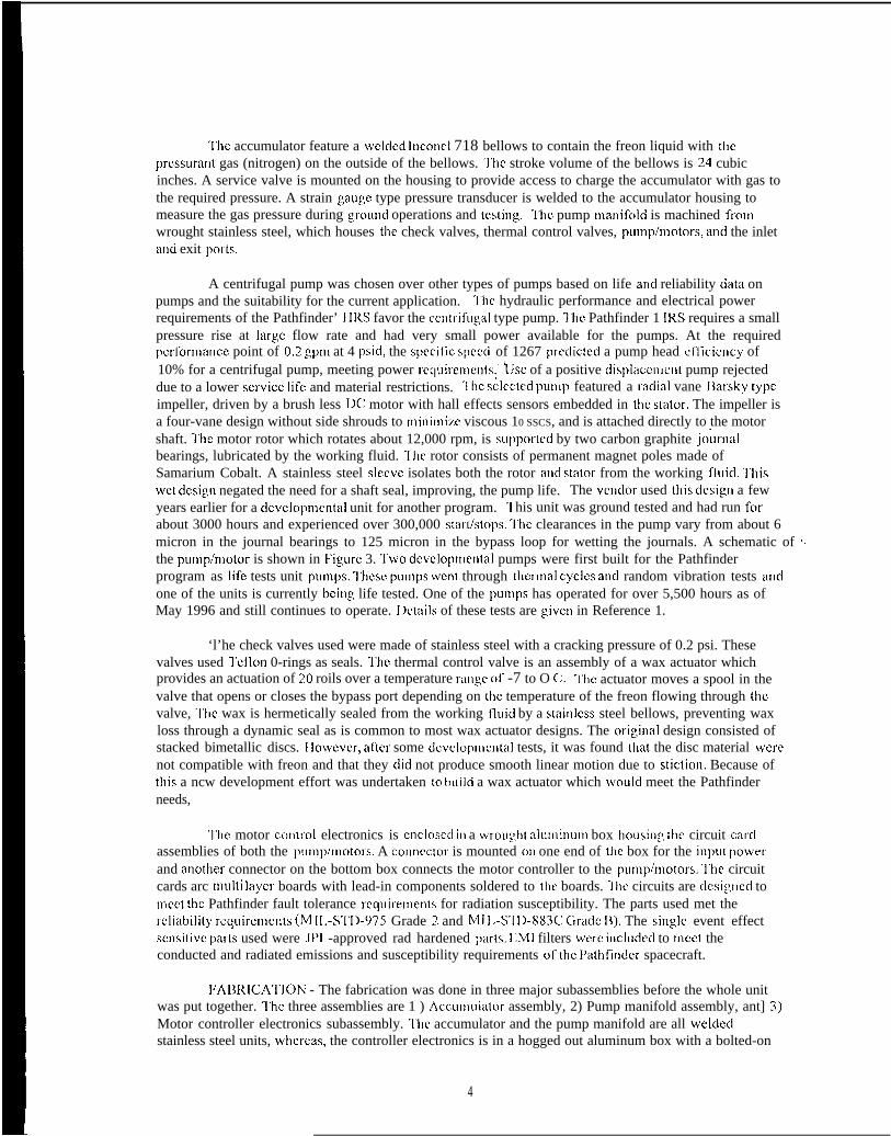
‘1’hc accumulator feature a welded Inccml 718 bellows to contain the freon liquid with thepressurant gas (nitrogen) on the outside of the bellows. I’hc stroke volume of the bellows is 24 cubicinches. A service valve is mounted on the housing to provide access to charge the accumulator with gas tothe required pressure. A strain gauge type pressure transducer is welded to the accumulator housing tomeasure the gas pressure during ~round operations and tesling. “1’he pump manifolcl is machined frcmwrought stainless steel, which houses the check valves, thermal control valves, pumphnotors, ancl the inletand exit porls.
A centrifugal pump was chosen over other types of pumps based on life ancl reliability ciata onpumps and the suitability for the current application. ‘1’hc hydraulic performance and electrical powerrequirements of the Pathfinder’ }11<S favor the cent!-ifugai type pump. ~’he Pathfinder 1 IRS requires a smallpressure rise at large flow rate and had very small power available for the pumps. At the requiredperfc,nnancc point of 0.2 gpm at 4 psid, the speci!~c. spce~l of 1267 prcclictcd a pump head cfliciellcy of10% for a centrifugal pump, meeting power rcquimuents.’ ~se of a positive displ:ic.enlent pump rejecteddue to a lower scrvicc Jifc and material restrictions. “1’hc s;]ected punlp featured a rziciial vane llarsky typeimpeller, driven by a brush less 1)(: motor with hall effects sensors embedded in the stator. The impeller isa four-vane design without side shrouds to minimim viscous 10 SSCS, and is attached directly to the motorshaft. I’he motor rotor which rotates about 12,000 rpm, is supported by two carbon graphite jo~malbearings, lubricated by the working fluid. “1’he rotor consists of permanent magnet poles made ofSamarium Cobalt. A stainless steel sleeve isolates both the rotor and stator from the working fluici. ‘1’hiswet design negated the need for a shaft seal, improving, the pump life. The vclidor used t}~is desigtl a fewyears earlier for a clcvelopmental unit for another program. 1 his unit was ground tested and had run fcmabout 3000 hours and experienced over 300,000 starl/stops. ‘1’hc clearances in the pump vary from about 6micron in the journal bearings to 125 micron in the bypass loop for wetting the journals. A schematic of I.the punlp/n]otor is shown in Figure 3. ‘IWO dcvclopn]ental pumps were first built for the Pathfinderprogram as ]ife tests unit pLnnps. l’hese pLImps wcnl through thcrmai cyc]es ancl random vibration tests anclone of the units is currently bcillg life tested. One of the pLlnlps has operated for over 5,500 hours as ofMay 1996 and still continues to operate. I)ctails of these tests are g,ivcn in Reference 1.
‘l’he check valves used were made of stainless steel with a cracking pressure of 0.2 psi. Thesevalves used ‘1’eflon 0-rings as seals. ‘1’hc thermal control valve is an assembly of a wax actuator whichprovides an actuation of 20 roils over a temperature ranp,e of -7 to O C, ‘1’he actuator moves a spool in thevalve that opens or closes the bypass port depending on the temperature of the freon flowing through thevalve, ‘1’he wax is hermetically sealed from the working fluicl by a stain]css steel bellows, preventing waxloss through a dynamic seal as is common to most wax actuator designs. The ori~ina] design consisted ofstacked bimetallic discs. }Iowever, af~cr some dcvelopmctltal tests, it was found that the disc material WCI-Cnot compatible with freon and that they clicl not produce smooth linear motion due to stiction. Because oft}lis a ncw development effort was undertaken to build a wax actuator which woLIlci meet the Pathfinderneeds,
‘1’he motor co[l[rol electronics is cncloscci it] a w’rou~,ht alulninum box housin: the circuit carclassemblies of both the pun~p/n~otors, A conneclor is mounted c)n one end of ~he box for the inpu( powdrand anottler connector on the bottom box connects the motor controller to the punlp/n]otors. I’he circuitcards arc multi layer boards with lead-in components soldered to the boards. ‘1 he circuits are dcsigrled torncet the Pathfinder fault tolerance rccluirernen[s for radiation susceptibility. The parts used met the1-cliability rcquircrnents (M II,-S’1’1)-975 Grade 2 and MI I,-S’1 1)-883C C]radc 11). The sing]c event effectscmsitivc parts used were JP1 -approved rad hardened parls. lIMI filters vverc irlcludecl to rncct theconducted and radiated emissions and susceptibility requirements ofthc Pathfincler spacecraft.
F’AIJI<lCA’I’IC)N - The fabrication was done in three major subassemblies before the whole unitwas put together. T’hc three assemblies are 1 ) Accurnuiator assembly, 2) Pump manifold assembly, ant] 3)Motor controller electronics subassembly. I’hc accumulator and the pump manifold are all weldeclstainless steel units, w}lercas, the controller electronics is in a hogged out aluminum box with a bolted-on
4

lid. I’bc welds were macle to qualified wclci schedules by MI I ,-S’1’1)-1 595 certifrecl weld operators. “1’hcsample welds were made on the day of the flight weld and inspected under high magnification for soundweld quality (depth ofpcnetration, porosily, cracks etc. ) before welding the actual hardware. The unit wasleak tested before proceeding with the next series of welds.
l’hc accumulator assembly consisted of the n]:ichined housing, the bellows, service wilvc, pressuretransducer, and purge tubing, All the parts were cleaned thotougbly to remove the parliculatcs above 25microns in size before the parts were assembled, tested, and welded. “l’he unit was tested for leak rate andbellows performance bctwccn each series of welcls. I :Icctron beam welds WCI-C used for all the welds in theaccumulator subassembly. After complctin!, the assembly, the pressure transducer output was calibratedamaillst pl-cssurc gage rcaclings.L>
All the motor assemblies, valves, and inlet and outlel tubing are asscnlbleci into the wrc)up,htstainless steel pLtmp manifold, All these pam arc welded into the block using laser wcldins. flccause ofthe nlagnctie properties ofthc motors, clcctr’on beam weld coLIIci not be used for this assembly. As in thecase of the accumulator fabrication, the pump manifolcl par 1s were cleaned and the unit tested between eachseries of wclcis. ‘1’hc tests consisted of checkin~, the performance of each pump, thermal control valve, andthe check valves before the next series ofwclcis were macle.
Iilcctronic box fabrication consisted of fabricating, the circuit cards and popul:iting, them withpat-ts. “J’bc multi layer circuit cards were fabricated to Mil-P-551 10. All the lead-in components weresoldered to the boards pcr the MI I .-S’1’1)-2000. ‘1’he boards were conformably coaled before they wereinstalled in the box.
l’he final dry mass of the 11’A before it was installed on the spacecraft came out to be 8.0 kg.
l)l{;IIFOILMANCE ‘1’IWI’S:
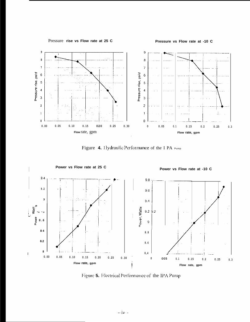
I’brcc types of performance tests were done on I PA: 1 ) 1 lydraulic, 2) I;lectrical, and 3) Systemproof and leak. I’hc hydraulic performance tests were conducted to verify that 11’A met the specific:itionrequirements. I’hese requirements related to the flow rate ancl prmsure rise at various tempclatures. TheIPA flow rate at various pressure rises is shown in l:i~,urc 4 for the 11’A with one pump operating,
in the clcct[-ical performance tests, the current cir-aw oftite lPA at various flow rates wasmeasured. ‘l’he input voltage to ti]e 11’A was vat-ied bctwccn ?.7 Vdc an(i 36 Vclc ancl the lllA current draww:is rncasured, I’ilc 1}’A clcctricai pet fonnance is si~owv) irl Figure 5.
ln order to verify the integrity of ttlc 11’A fabrication, tllc unit was proof tested and ieak cilccked.The unit was successfully testc(i 10 a proof pressure of 185 psi?,, “Iwo leak rates were specified for tile I PA- onc for tile gas side of tile accumulator anti a scconci for the rest of the unit Ivhich is ti]e Iiquici siclc. l:orthe gas side, tile maximum icak ra[e was specified at 2 .X i 0-- SCCJSCC of hciium, whereas for tile liquid side,it was specified as 1 x 10-”’ scc/sec heiium. 3 he leak rates for each wcicl arlci vziive were computed basccion ti~csc totai leak rates nnci were tested to tile cornputc[i icvels during, tile leak cileck of the assen~bly.
QUAl,IFICA’1’ION ‘J’M’I’S:
‘1’i~rcc types of qualification tests were clone on li’A bcsi(ics thr pcr-fonrlancc tests. These arcvitmition tests, tilcrmal vacuum tests, and llicctrornagnctic compatibility anti susceptibility tests, “1’i]cievcis to which the unit was tested were protoilig,ilt icveis since tile fligilt unit was used instead of anen~, ineering modei to fli~,ht qoalify the 11’A, ‘1’he order of the acceptance tests arc ~,ivcn in ‘1’abic ?.
‘1’abic 2. Acccptancc “1’csts for the i PA

Type of testTerformancc tcstiSine Vibration testsRandom Vibration tests
T’hcrmal Vacuunl testl~unctioual testl’roof pressure test1 ,calc i)etection testJ’erformance tests
VcrificatiG3ZrposePerformance of the 11’A before the start of the qualification testsI)esign for the protoflirght launch loadsI)csiga for the protoflight launch loadsI;unctionality of the unit afler an acceptance testI)esign for the protoflight tcmpcratorc rangeE’unctionality of the unit af[cr an acceptance testIlesip)n for the operating pressure1,cak rates of the 11’Al’erfonnance of the lPA at the completion of qualification tests
'l't]etest requiret]]el]ts forttlc Sitlcarld Rat~dolll vibra[iotl aregivell ir]"l'ablc3. ‘I’]le]}’A sLlcccssfutlyunc{crwm]t these tests while both the polnps wc]e operating. “1’bc pcrforinance was monitored during theactua] vibration. “I’hesine vibl”ation test collsisted ofs\$`eellillg atttlcsJJccified sillLlsoiclat amplitude !evcisfrom the lowest frequency to the highest frequency and back to the lowest frequency at a rate of2octaveshninute in each of the three orthogonal axes. The ]andom vibration tests was conducted one minuteper axis. Accelerometers used to monito~ the responses cluring both the tests,
‘l’able 3. Sine and Random Vibration specification for the 11’A
l< AN1)Ohl VI BllA’1’10N:411
l’rotoflight T’est J ,cvel
] .27 crn double ampiitudc10.0 g (Acceleration O-to-peak)
-I 6ci11/octaveo.2g?/Ilz-12 dlUoctave13.2 g;,,,,,
kkcquency IIand
5-2011?,
~fj -80 }]z80-700117,700-2000117,C)verall
‘1’he thermal vacuum test 01) the 11’A consislcd of two types of tests. ‘[’he first test was cione on then]otor controller electronics separately. The electronic box w:is mounted on a base p]atc which maintainedat 70 C while both pLIn~ps were conti]luoosly on for a seven-day period, Iilectrical simulated loads wereused for the pumps in this test. ‘J’hc second thrmnal vacuum test was conducte(i on the whole lPA andconsisted of one-day COICI ancl two-day hot soak, l’he testy requirenlents are shown in F’igure 5.
‘]’hc ~iVf[ cluaiificnLion tesls for conduclcd Lm]ssior]s and Susceptibility were cione on a separatelife test punlp/mo~or unit which was of the same ciesign as the flight punlp/motor unit and the ffi~h[elrctmnics. ‘l”he FIMI test) performed for the power line ripple and power line transients for bothemissic)ns and susceptibility, The lLM1 qualification tests for radiated emissions ant] susceptibility wwreperformed at the spacecraft level. “1 he lllA went tl]rou~,l] the tests and satisfactorily met the spacecraftrequirements.
I) RIIXJCN’l’ S’1’A’J’LJS:
‘1’he lPA has been integrated with the rest of the 1 IRS on the I’athfindcr spacecraft. ‘1’he spacecraf[went throu:h an acoustic test to simulate the launch vibration conclitions. The 11’A has been per fcwmingwell. The spacecraft will unclerg,o a solar vacuum test in A pI i] 1996 to simu]atc the mission cruiseconditions of solar flux and the space thermal environment. I)uring this test, the 11’A will be operated inflig,ht-lilcc conditions. ‘1’hc tcrnpc.ratures of the entile }1}{S will be mc~nitored along with the accumulator
6
flight-like conditions. I’he temperatures of the entire llKS will be monitored along with the accLmlulatorgas pressure. I’he performance of the llRS and 11’A will be evaluated and compared to tbc earlieranalytical predictions.
CONC1,LJS1ONS ANl) ItlCOh~NlltNI)ATIC) NS:
‘l’he design and flight implenmrtation of the Integrated I’Lln~p Assembly for the I Ieat RejectionSystem of Mars Pathfinder spacecraft was successfLllly accomplished in less than eighteen months. I’hisquick turn around for a ncw spacecraft tecbnolo?,y was achieved by employing non-tmclitional techniquessuch as parallel work on the dcvcloprncntal and flis,ht units, flight quatificatiorl to prc)toflight levels, tradiagoff schedule and cost against risks during the i[l~l>lert]et]t~~tior~, and quick decision on tbc design changes tofix problems encountered during the clesiga verification.
‘1’be modular design of the I PA macle it easier to Fdbricate and test electronics :ind the n]echanicaiparts ofthc assembly independently and expcclitiously. A new wax actuated thermal control valve wasdeveloped for the 11’A for bypassing the rtidiator for lluid tetnpcl-aturc below O C. The lf’A wassucccssfLilly assembled using extensive electron beam and laser weld’ing. “J’he bi?,h level of cleanlinessrequired for the lPA during assembly and test was achieved by employing carefLll handling prmccdurcs.Me 11’A has been soccm+fLIily inslallcd in the sp:icecraft heat rejection system and tested.
I]ecausc it was the first time an active cooling systcrn was being implemented on a spacecraft,several lessons were Iearmed from the flight implementation of the lPA on the Pathfirrdcr. l’hese are in theareas of design, fabrication, ancl testinp, ofthc pLln]p assembly and integtati[lg it on the spacecraft. Someof these include design modifications to make the wclclinp, process easier, elimination of some intermediatecleaning processes by better handling of the hardware, and using iiqLlid nitrogen to perform some of thecold tests. Further, the cooling system design itself can bc improved for foture spacecraft by employingmore advanced concepts for lPA sLlch as variable speed motors, advanced ttlcrlnal valves, feedbacksystems for flow control, and low mass accLinlulators.
‘1’hc work describcci in this papct- was car~icd oLlt at the Jet PrcJpL]lsion 1,aboratory, California]nstitutc of l’echnolog,y, Pasadena, Califon]ia under a contract with the National AeronaLltics and SpaceAdministration.
‘l’he design and flight irnplefncntation of the I PA could be accomplished Llndcr a very tightschedule (Llnder two years for new technology flight item) dLle rnaialy to extreme cooperation and supportof many people. ‘1’hc authors would like to acknowlcdp.c the following persons. At J!’I,, IIill layman, }~d1 itly. (ire:, I<osa]ia, I<icharcl l{ainen. Andre YavrclLlvian. atlcl Rob h~ellke for their sLlpJXrr[ for the [}’.~ task:Chris Mirate, Jack l’awold, Richard F’leiscbner, and Jay IkWirlgcr for the ir]~[~ler]]erlt:{tior~ c)fthe 11’.4 irltothe spacccrafl; Yi-Chicn Wu, the Therlnal sLlbsyslcnl task rnanag,er’, for }lis constant soppcm and faith in LIS;and finally, Ilrian Muirhcacf, the f’zithilncler Si~acccrafl Manager, for his Imdership in choos in: the activecooling loop for Mars I’athfinckr and sLlppc)l-t dLlring the design anti flight inlplcnlenlalio]i of the I} ’A. At] lowden llL]id. Systenls; Scot[ Forbes, Chief 11’A technicizin, for ably taking care of the entire fabricationanti testi[lg of the 11’A f’tom the beginning. Richard I;ischer, ljircclc~r of }.ngirleerinp,, Ilill Young, ChockI;orbes, Mitch J~rey, and Rich Ikmmorc for their sLlppcJr[ for the dcsig,n and tcstinp, of the lf’A; 1,arryNowiin, tbc Program Manag,cr fc)r Ii’A, for expeditiously resolving nlany difficLlit problems cluring thecxecLltion of the task.
7

1. Flhandari, P., BirLm, G., and Gram, M., “Mechanical Pumped Cooling I,oop for Spacecraft‘1’hermal Control,)’ Jx’esented at the 26dl international Conference on Ilnvironrnental Sciences, Monterey,California, July 8-11,1996.
7-. lIC I’aolis, M., ‘(A controlled Pump Asscssrnent for Spacecraft (oolin~,,” Thermal Control and}leat I<ejcctior~ Sectior~, I;S'I'IIC," l"lleNctllcrlar~ds, I' I'l'll-l62,\~ol. 18,11 SAJoLrrnal, 1994.

Integratecl f“urnp Assembly
Ven[ Cccmnemon
Gas fill port ~(-j . . . . . . . . . - - - - - - - - . ..- . . . . . . . ..-. . . - - - - . .
“kvent R
A c c u m u l a t o r wnnec!fOG
L
1.1.1 cmneckm
;-----o——————
-----(L, I
jp-, 8I Purqe pod
L-,t,;
. . . . ’ . . . . .SIC :
. . . . . . . .,---- . .
— IP/I
Conhol valve
0--+
Check valve
+ P/M x --41--
P..,plnmw
+
cD
Cl--Q ~+ P/M x
W=. O.tlelCmnccwn
?
Vent A
–Lo----0,11,1 Cor,”ec( <o,,
,,FIII pod ,
. . . . . . . . . . . . . . ...!. .,, .
III. . . . . ...! . . ...< I
---- --- L a n d e r ;. .. _ _ _ lR(lVf R:--- .-. --. i_... . . . . . . . . . . . . Crutse Rad(atorElectronics I . . . . . .
. . . . . . . . . .. . . . . . . . . . . . . . . . . . . . . .
l~iguw 1. IMegratecl Pump Assembly IIyciraulic Schmatic
“vi!IllL [,
(6$41 ‘- -
idL-m”-; ‘-~.
@
.O1. + . .
I0 0 0
0.OOOOO di )1 I-—- -.-— ---- —-.I I
“jI
I
l~igurc 2. lPA Mmhanical
-..$> ,/
-+ltiL.~ “r

.-i-)
z:r _
“ w-1
I4
I
‘J
\ /~.—.—z—.—.
I
L ---------- . . . .
I
II
I
I
1
I
!)
- - - -
. .,—.——~.-~ \.1-.
----- .--L .-f&. -
-’-T-.,p--’-(-, .,
‘! ,.-—
,,,.7 —
,—
-1
Pressure rise vs Flow rate at 25 C
9
8
7
2
1
0
0.00 0.05 0.10 0.15 020 0.25 0.30
Flow rate, gpm
I9.4
9.2
I9
In
~ ~ 8“ 8 ”I
~.
~ 8.6c?
8 4
8.2
8
Pressure vs Flow rate at -10 C
---1 ~I . . . . ,..— I I. . . . . . . . . . . . . . . . . . . . . . . .
0 0.05 0.1 0.15 0.2 0.25 0.3
Flow rate, gpm1’
Figure 4. 1 ]ydraulic Pcrformatlce of the I PA Pump
Power vs Flow rate at 25 C
‘“-–- T-–-----”-
.1..
I
,.–
~0.00 0.05 0.10 0.15 0.20 0.25
Flow rate, gpm
0.30
Power vs Flow rate at -10 C
I
9.8 —----
9.6
9.4
m
-1
% 9.23k3 92
8.8
8.6
8,4i
0.
/
005 0.1 0.15 0.2 0.25 0.3
N’igure 5. lllcctrical l’erformance of the 11’A Pump
Flow rate, gpm

Warn! up vdh both pumps on Seven day hc,t soak, base plate(srnulaled load), at 1 abn mannwm at 70” C, boti! pumps on
(1 X 10“4 Torr ok), Operab”g aI 36 !Jdc, (%mulaled load) opcrabrig a!
1 hour m[mn]um 36 Vdc, al 1 X 10”4 Torr or lower
I \1
Y$tB
7 0 - - - - - - i
Temperature, “C
25 -A
I II
~i. .l 1 I I , ,0 1 2 3 4 5 6
Ilme, Cays
Cool dovwl ‘MM) both pU”,OSoff (simulated load), al 1 a{mmaamunl. 1 hour n),r,,n,un,
1 I7 8
a)-l’hcrmal Qualification ‘1’est forthch40tor Co]ltrollcr I11ectronics
Thermal/vacuun~ test for Integrated Pump Assembly
50
Temperature, C
25
-40
0
30 Clhr or
c ~...-
‘--”71
/
Yless
l’A B
6 30 36
Two day hot soak:
A
Base plate at 50 C and both pumpoperating at 36 Vdc and flllid term
floating (above 30 C)
30 C/hr or less
D NOTE I:Chamber vacuun, of1X 104 Torr or lower
L
One day cold soak:baso plate at 40 C and both pumpsoperating at 36 Vdc fluid floattng (below .15)
llme, hourb
b) ‘J’hmnal Qualification ‘J ‘est for
Note 2:A Pump onB Pump offC Punlp o nD Pump off
StORs/stark:3 statistopsbetween A-B
3 starthtopsbetween C-D
74 76
th~ 1 PA with lllectronics
h’i:,um 6. II)A ‘1’hcrmal Qualification ‘1’cst Cycle
--il–-