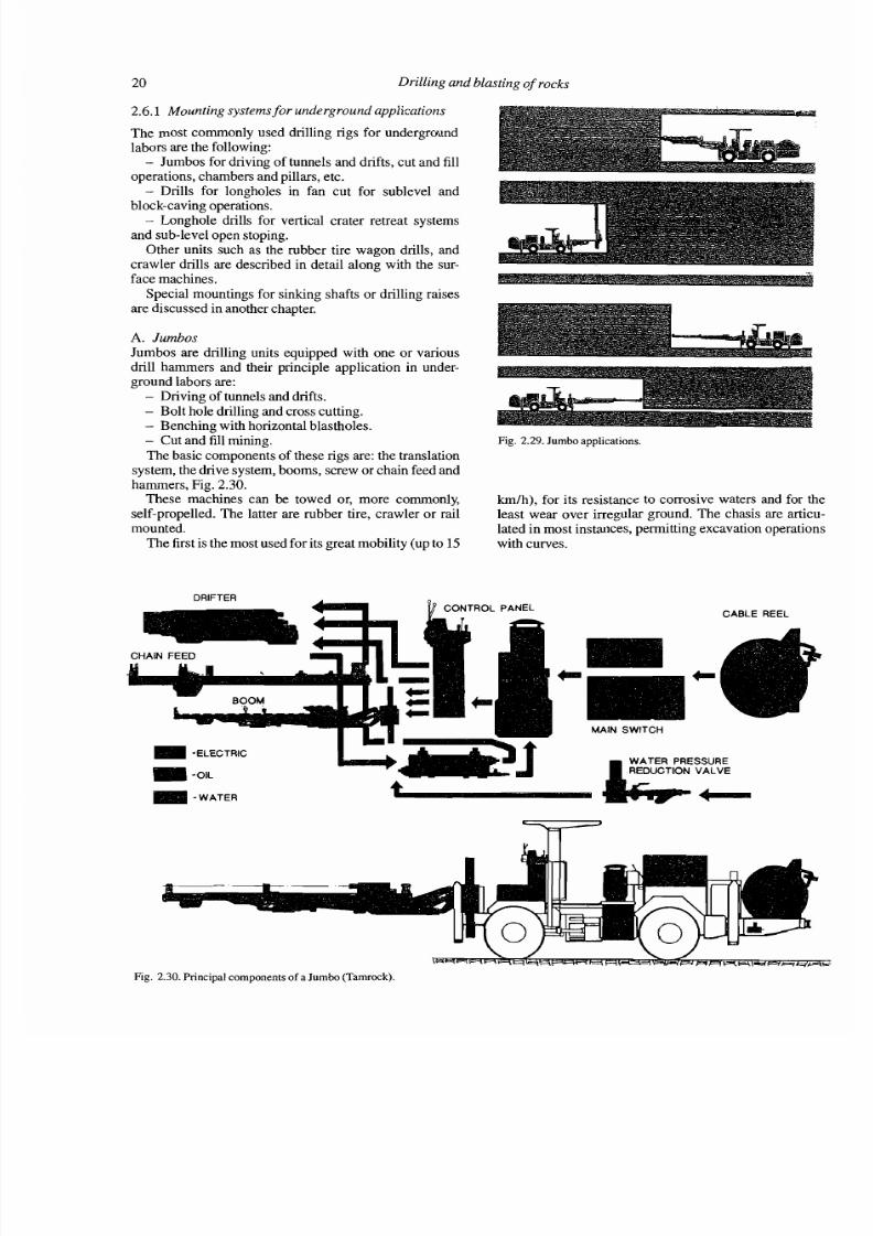
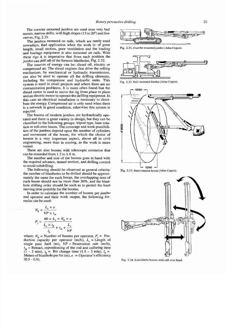
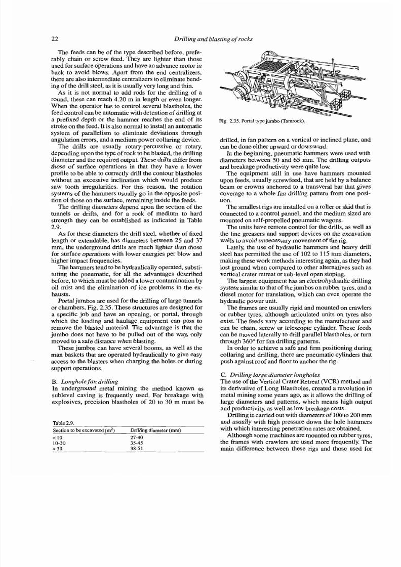
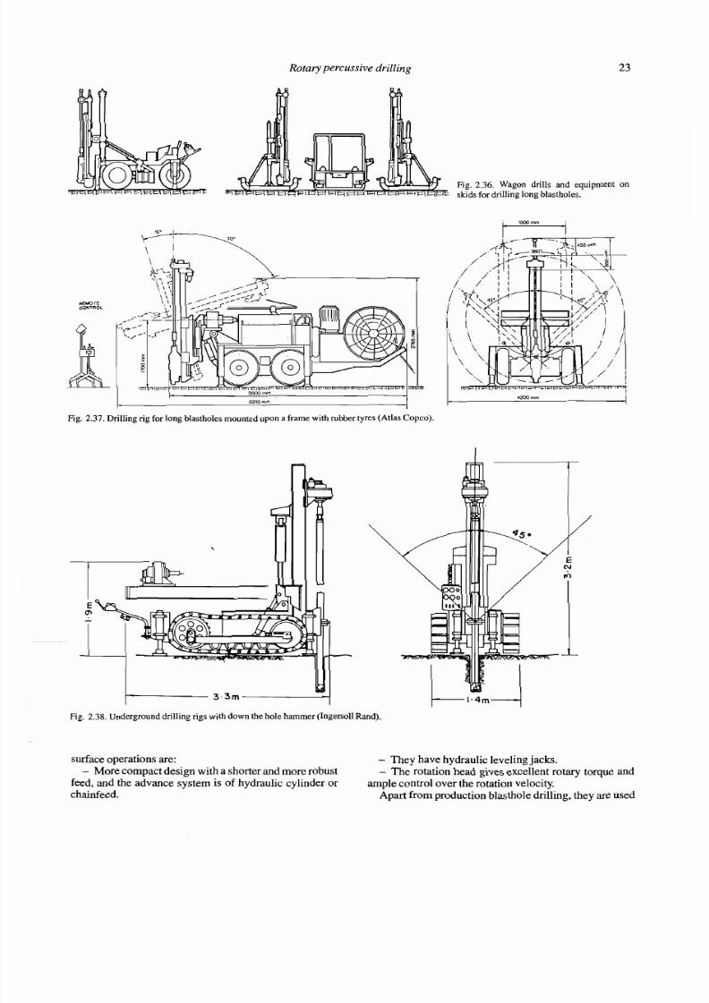
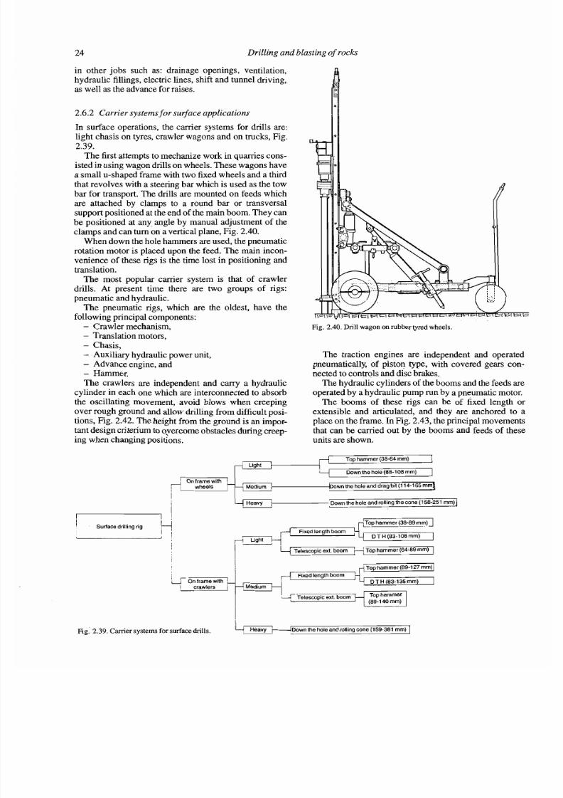
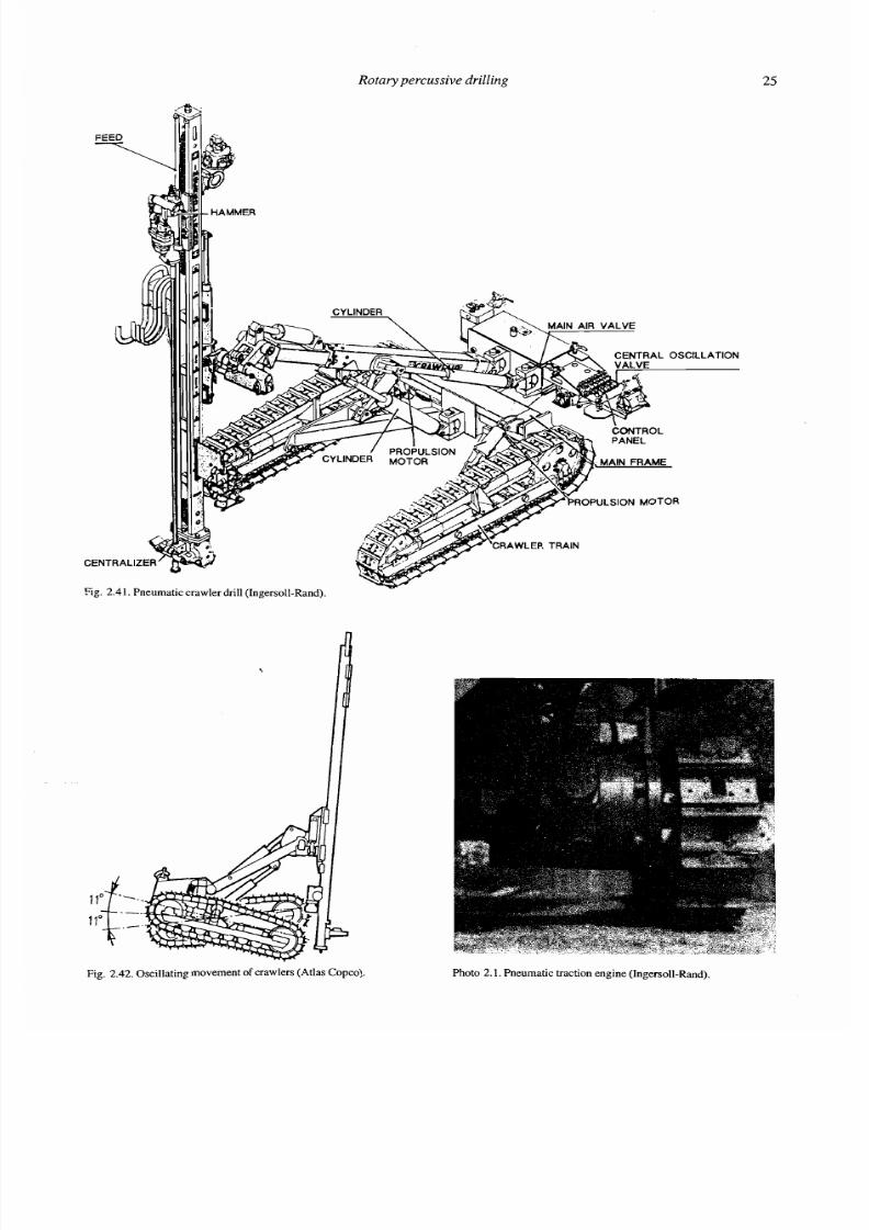
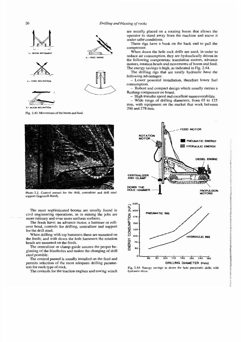
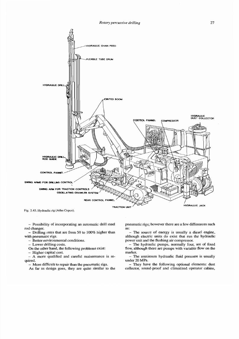
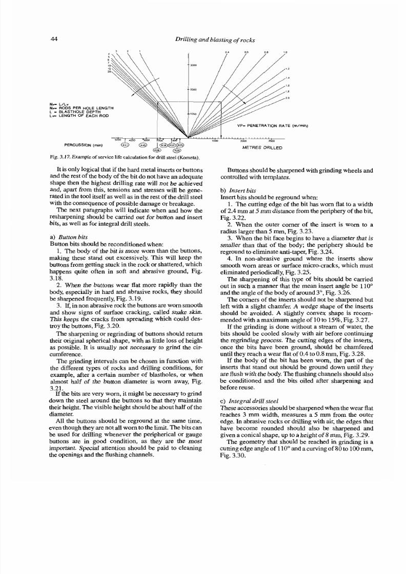
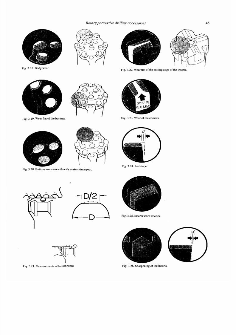
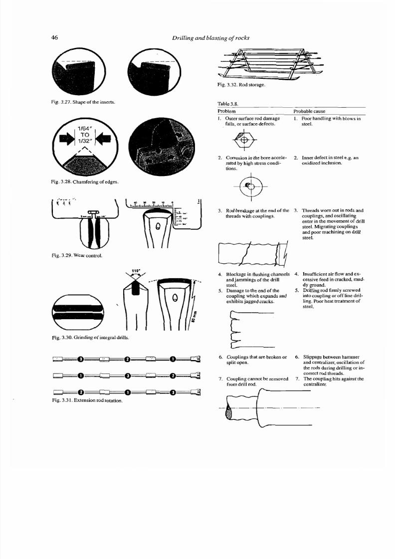
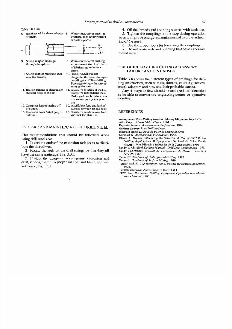
drilling and blasting in rocks (sample)
TRANSCRIPT

7/28/2019 Drilling and Blasting in Rocks (sample)
http://slidepdf.com/reader/full/drilling-and-blasting-in-rocks-sample 1/81

7/28/2019 Drilling and Blasting in Rocks (sample)
http://slidepdf.com/reader/full/drilling-and-blasting-in-rocks-sample 2/81
This work has been totally financed by the G eornining Technological Institute of S pain under contract with the E.F?M., S.A. Cornpany(Estudios y Proyectos Mineros, S.A.).
Authorization to photocopy iterns for internal or personal use, or the internal or personal use of specific clients, is granted byA.A.Balkerna, Rotterdarn, provided that the base fee of US$1.50 per copy, plus US$O.lO per Page is paid directly to CopyrightClearance Center, 222 Rosewood Drive, Danvers, MA 01923, USA. For those organizations that have been granted a photocopy
license by CCC, a se parate systern of payrnent has been arranged. The fee code for users of the Transactional Reporting Service is:90 5410 199 7/95 US$1.50 + US$O. 10.
Original text:Manual de perforacion y voladura de r ocas
O 1987 Instituto Geologico y Minero d e E spaila
Revised and updated ed ition in English:
O 1995 A.A. Balkerna, PO. Box 167 5,30 00 BR Rotterdarn, Netherland s (Fax: +3 1.10.4135947)
Distributed in USA & Canad a by:A.A. Balkema Publishers, Old Post Road, Brookfield, VT 05036, USA (Fax: 802.276.3837)
Printed in the Netherlands
7/28/2019 Drilling and Blasting in Rocks (sample)
http://slidepdf.com/reader/full/drilling-and-blasting-in-rocks-sample 3/81
Contents
FOREWORD
PREFACE
ACKNOWLEDGEMENTS
1 ROCK DRILLING METHODS1.1 Introduction1.2 Types of drilling operations used in rock
breakage1.3 Field s of applica tion for the different drilling
methods1.4 Classification of the rocks and their
principal physical propertiesReferences
2 ROTARY PERCUS SIVE DRILLING2.1 Introduction
2.2 Fundamentals of rotary percussive drilling2.3 Top hammer drilling2.4 Dri lling with down the hole harnmer2.5 Advance systems2.6 Mou nting systems2.7 Dust collectors2.8 Inclination instruments2.9 Penetration rate2.10 Average penetration rate2.1 1 Calculation of drilling costsReferences
3 ROTARY PERCUSS IVE DRILLING
ACCESSORIES3.1 Introduction3.2 Types of threads3.3 Shank adaptors3.4 Dnl l steel3.5 Couplings3.6 Dnl l bits3.7 Calculatio n of the necessary drilling
accessories3.8 Care and maintenance of the bits3.9 Care and maintenance of drill steel3.10 Guide for identifying accessory failure
and its causesReferences
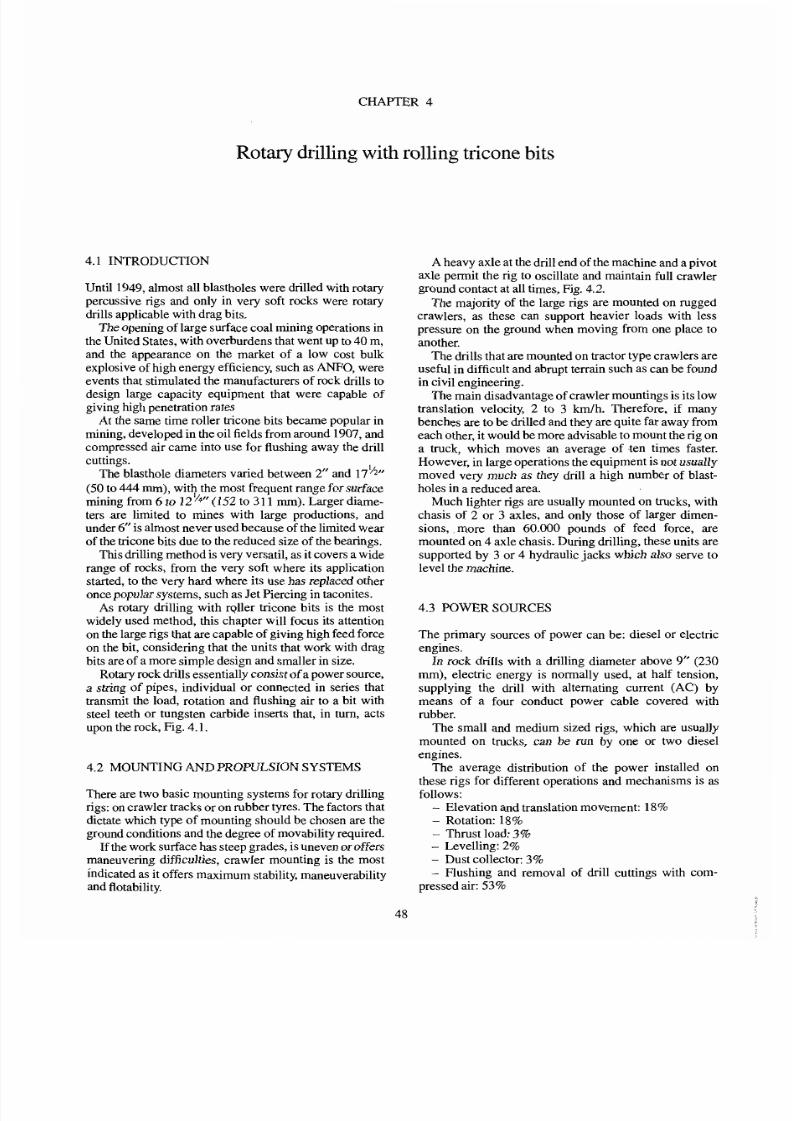
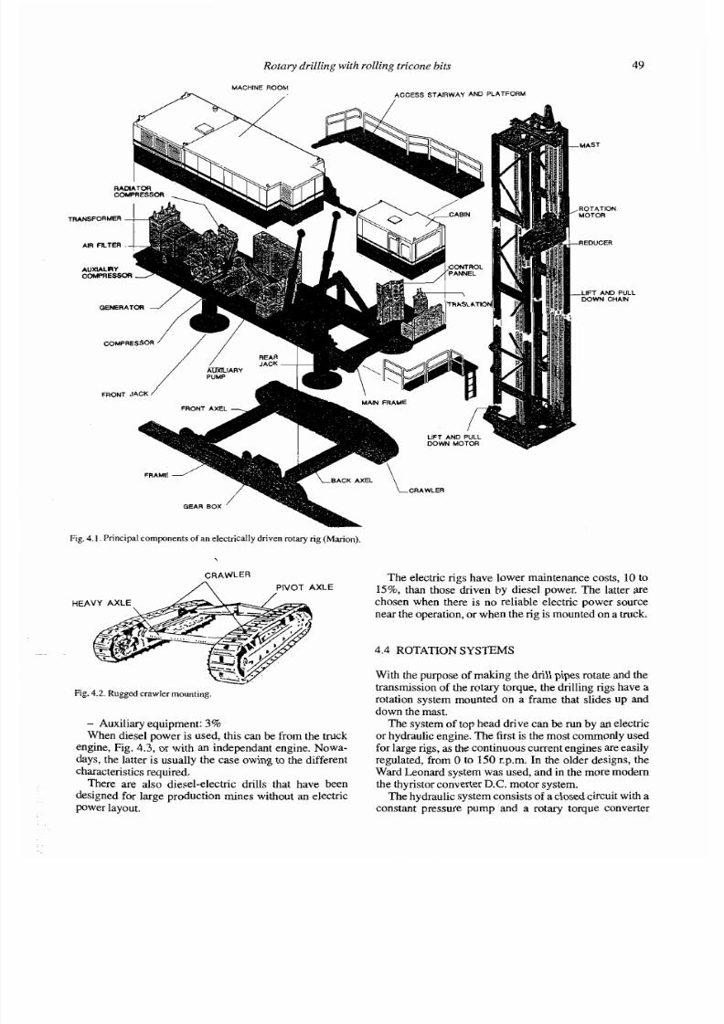
4 ROTARY DRILLING WITH ROLLINGTRICONE BITS4.1 Introduction4.2 Mounting and propulsion systems4.3 Power sources4.4 Rotation systems
4.5 Pulldown /hoisting systems4.6 Mast and pipe changer4.7 Control cabin4.8 System for flushing drill cuttings4.9 Dnl l string4.10 Auxiliary elements4.1 1 Operative practice. Drilling parameters4.12 Penetration rate4.13 Calculation of drilling costsReferences
5 ROLLING CONE ROCK BITS
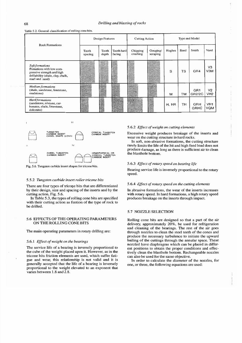
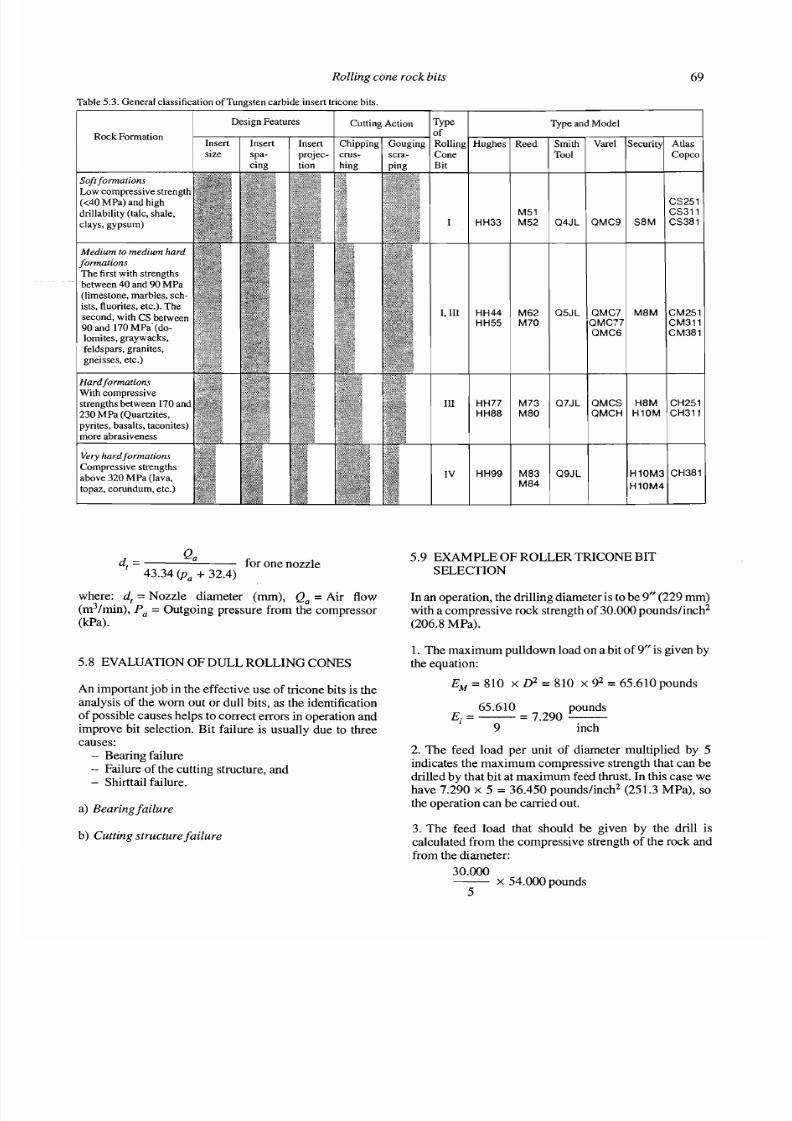
5.1 Rolling cone rock bits5.2 Major compo nents and design features5.3 The metallurgy of rolling cone rock bits5.4 Types of rolling cone bits5.5 Bit type selection5.6 Effects of the operating parameters on the
rolling cone bits5.7 Nozzle selection5.8 Evaluation of du11 rolling cones5.9 Example of roller iricone bit selection5.10 IDAC CodesReferences
6 ROTARY DRILLING WITH CUTTIN GACTION6.1 Introduction6.2 Fundam entals of drilling with cutting action6.3 Flushing of drill cuttings6.4 Cutting toolsReferences
7 SPECIAL DRILLING METHODS ANDMOLINTING SYSTEM S7.1 Introduction7.2 Drilling through overburden
7.3 Shaft sinking7.4 Raise driving

7/28/2019 Drilling and Blasting in Rocks (sample)
http://slidepdf.com/reader/full/drilling-and-blasting-in-rocks-sample 4/81
Contents
7.5 Jet piercing7.6 Water-jet drilling7.7 Drilling ornamental rockReferences
8 COMPRESSORS8.1 Introduction8.2 Types of compressors8.3 Drive8.4 Auxiliary elements8.5 Calculating pressure dropsReferences
9 THERMOCHEM ISTRY OF EXPLOSIVESAND THE DETONATION PROCESS9.1 Introduction9.2 Deflagration and detonation9.3 Detonation process of an explosive9.4 Thermochemistry of the explosives9.5 Heat of explosion9.6 Oxygen balance9.7 Volume of explosion9.8 Minimum energy available9.9 Temperature of the explosion9.10 Pressure of the explosionReferences
10 PROPER TIES OF EXPLOSIVES10.1 Introduction10.2 Strength and energy
10.3 Detonation velocity10.4 Density10.5 Detonation pressure10.6 Stability10.7 Water resistance10.8 Sensitivity10.9 Detonation transmission10.10 Desensitization10.11 Resistance to low temperatures10.12 FumesReferences
11 INDUSTRIAL EXPLOSIVES11.1 Introduction11.2 Dry blasting agents11.3 Slurries11.4 Emulsions11.5 Heavy ANFO11.6 Gelatin dynamites11.7 Granular dynamite11.8 Permissible explosives11.9 Blackpowders11.10 Two-component explosives11.11 Explosives cornmercialized in SpainReferences
12 EXPLOSIV E SELECTION CRITERIA12.1 Introduction
12.2 Explosive cost12.3 Charge diameter12.4 Rock characteristics12.5 Volume of rock to be blasted12.6 Atmospheric conditions
12.7 Presence of water12.8 Environmental problems12.9 Fumes12.10 Safety conditions12.11 Explosive atmospheres12.12 Supply problemsReferences
13 BLASTING ACCESSORIES 12392 13.1 Introduction 12392 13.2 Nonelectric initiation systems 12392 13.3 Electric initiation systems 12793 13.4 Sources of energy 13094 13.5 Other accessories 13294 References 1359595 14 INITIATION AND PRIMING SYSTEMS 13696 14.1 Introduction 13696 14.2 Priming and boostering bulk ANFO-type96 blasting agents 13697 14.3 Priming cartridge ANF O type blasting
agents 13898 14.4 Priming pumped or poured slurry and98 emulsion blasting agents 13998 14.5 Priming cartridged watergel and emulsion
101 blasting agents 140102 14.6 Location of primers 140102 14.7 Priming conventional cartridged102 explosives 143102 References 143102103 15 MECHANIZED SYSTEMS FOR CHARGING104 AND DEWATERING BLASTHOLES 144104 15.1 Introduction 144104 15.2 Mecha nized blasthole charging Systems 144105 15.3 Blasthole dewatenng Systems 152
References 153
106106 16 MECHANISMS OF ROCK BREAKAGE 154106 16.1 Introduction 154110 16.2 Rock breakage mechanisms 154111 16.3 Transmission of the strain wave through113 the rock mass 156115 16.4 Energetic yield of the blastings 157115 References 159116116 17 ROCK AND ROCK MASS PROPERTIES117 AND THEIR INFLLTENCE ON TH E117 RESULTS O F BLASTING117 17.1 Introduction
17.2 Rock properties119 17.3 Properties of the rock mass119 References

7/28/2019 Drilling and Blasting in Rocks (sample)
http://slidepdf.com/reader/full/drilling-and-blasting-in-rocks-sample 5/81
Contents V11
18 CHARACTERIZATION OF THE ROCKMASSES FOR BLAST DESIGNING18.1 Introduction18.2 Diamond drilling with core recovery and
geomechanic testing
18.3. Characteristics of the joint systems18.4 Seismic survey18.5 Geophysical techniques to obtain rock
mass data18.6 Logging of production blastholes18.7 Characterization of the rock mass during
blasthole drilling18.8 The attempt to correlate drilling indexes
with the blasting design parameters18.9 System of drilling data management in
actual timeReferences
19 CONTROLLABLE PARAMETERS OFBLASTING19.1 Introduction19.2 Blasthole diameter19.3 Height of bench19.4 Blasthole inclination19.5 Sternrning length19.6 Subdrilling19.7 Burden and spacing19.8 Blastho le patterns19.9 Geometry of the free face19.10 Sizean dshap eof the blast
19.1 1 Available expansion volume19.12 Charge configuration19.13 Decoupling of the charges19.14 Explosives19.15 Distribution of explosives in the
blastholes19.16 Powder factor19.17 Initiation and priming19.18 Delay timing and initiation sequences19.19 Influence of loadinieq uipment on the
design of the blasts19.20 Specific dtilling19.21 Blasthole deviationReferences
20 BENCH BLASTING20.1 Introduction20.2 Small diameter bench blasting20.3 Large diameter blasting20.4 Bench blasting with horizontal blastholes20.5 Rip-rap production blasting20.6 Cast blastingAppendix 1 Formulas to calculate benchblasting patternsReferences
21 BLASTING IN OTHER SURFACEOPERATIONS2 1.1 Introduction2 1.2 Excavations for highways and railways
21.3 Trench blasting 208167 2 1.4 Ramp blasting (sinking cut) 210167 2 1.5 Blasting for ground leveling 212
21.6 Blastings for foundations 213167 21.7 Mini-hole blasting 2 14
167 2 1.8 Preblastings 215170 References 216
170 22 BLA STING FOR TUNNELS AND DRIFTS 217170 22.1 Introduction 217
22.2 Advance systems 217171 22.3 Blasting Patterns for tunnels 218
22.4 Types of cuts and calculation of the blasts 219174 22.5 Equipment for marking out dtilling
patterns 230177 References 230178
23 SHAFT SINKIN G AND RAISE DRIVING 23 123.1 Introduction 23 1
179 23.2 Shaft sinking 23 1179 23.3 Raise driving 232179 References 237181181 24 UNDER GROUND PRODUCTION BLASTiNG182 IN MININ G AND CIVIL ENGINEERING 239182 24.1 Introduction 239183 24.2 Crater retreat method 239183 24.3 Longho le method 243184 24.4 Sublevel stoping with blastholes in fan185 pattern 245
186 24.5 Room and pillar mining 248186 24.6 Cut and fill mining 248186 24.7 Underground chambers in civil187 engineering projects 249
References 25 1187188 25 CONTOUR BLASTiNG 252188 25.1 Introduction 252188 25.2 Mechan isms responsable for overbreak 252
25.3 The theory of contour blasting 253189 25.4 Types of contour blasts 254189 25.5 Th e parameters that intervene in a190 contour blasting 256190 25.6 Tendencies in the field of contour blasting 264
25.7 Evaluation of the results 267191 25.8 Exarnple 268191 25.9 Extrac tion of ornamental rock with191 contour blasting 268193 References 270195195 26 UNDERWATER BLASTiNG 272196 26.1 Introduction 272
26.2 Methods of execution 272199 26.3 Calculations for charges and drilling203 patterns 247
26.4 Charg ing the blastholes and primingsystems 275
205 26.5 Types of explosives 276205 26.6 Env ironmental effects associated with205 underwater blastings 276

7/28/2019 Drilling and Blasting in Rocks (sample)
http://slidepdf.com/reader/full/drilling-and-blasting-in-rocks-sample 6/81
Contents V11
18 CHARACTERIZATION OF TH E ROCKMASSES FOR BLAST DESIGNIN G18.1 Introduction18.2 Diamond drilling with core recovery and
geomechanic testing18.3-
Characteristics of the joint system s18.4 Seismic survey18.5 Geophysical techniques to obtain rock
mass data18.6 Logging of production blastholes18.7 Characterization of the rock mass during
blasthole drilling18.8 The attempt to correlate drilling indexes
with the blasting design parameters18.9 System of drilling data management in
actual timeReferences
19 CONTROLLABLE PARAMETERS OFBLASTING19.1 Introduction19.2 Blasthole diameter19.3 Height of bench19.4 Blasthole inclination19.5 Sternming length19.6 Subdrilling19.7 Burden and spacing19.8 Blasthole patterns19.9 Geometry of the free face19.10 Size and shape of the blast
19.11 Available expansion volume19.12 Charge configuration19.13 Decoupling of the charges19.14 Explosives19.15 Distribution of explosives in the
blastholes19.16 Powder factor19.17 Initiation and prirning19.18 Delay timing and initiation sequences19.19 Influence of loadingequipment on the
design of the blasts19.20 Specific drilling19.21 Blasthole deviation
References
20 BENCH BLASTING20.1 Introduction20.2 Small diameter bench blasting20.3 Large diameter blasting20.4 Bench blasting with horizontal blastholes20.5 Rip-rap production blasting20.6 Cast blastingAppendix 1 Formulas to calculate benchblasting patternsReferences
21 BLASTING IN OTHER SURFACEOPERATIONS21.1 Introduction21.2 Excavations for highways and railways
21.3 Trench blasting 208167 21.4 Ramp blasting (sinking cut) 210167 21.5 Blasting for ground leveling 212
21.6 Blastings for foundations 213167 21.7 Mini-ho le blasting 214
167 2 1.8 Preblastings 215170 References 216
170 22 BLASTIN G FOR TUNNELS AND DRIFTS 217170 22.1 Introduction 217
22.2 Advance systems 217171 22.3 Blas ting Patterns for tunnels 218
22.4 Types of cuts and calculation of the blasts 219174 22.5 Equipm ent for marking out drilling
patterns 230177 References 230178
23 SHAFT SINKING AND M I S E DRIVING 23 1
23.1 Introduction 23 1179 23.2 Shaft sinking 23 1179 23.3 Raise driving 232179 References 237181181 24 UNDERGROU ND PRODUCTION BLASTING182 IN MIN ING AND CIVIL ENGINEERING 239182 24.1 Introduction 239183 24.2 Crater retreat method 239183 24.3 Longhole method 243184 24.4 Sublevel stoping with blastholes in fan185 pattern 245
186 24.5 Room and pillar mining 248186 24.6 Cut and fill mining 248186 24.7 Underground chambers in civil187 engineering projects 249
References 25 1187188 25 CONTOUR BLASTING 252188 25.1 Introduction 252188 25.2 Mech anisms responsable for overbreak 252
25.3 The theory of contour blasting 253189 25.4 Types of conto ur blasts 254189 25.5 Th e parameters that intervene in a190 contour blasting 256
190 25.6 Tendencies in the field of contour blasting 26425.7 Eva luatio n of the results 267
191 25.8 Exam ple 268191 25.9 Extraction of ornamental rock with191 contour blasting 268193 References 270195195 26 UNDERW ATER BLASTING 272196 26.1 Introduction 272
26.2 Metho ds of execution 272199 26.3 Calculations for charges and drilling203 patterns 247
26.4 Charging the blastholes and primingsystems 275
205 26.5 Types of explosives 276205 26.6 Environm ental effects associated with205 underwater blastings 276
7/28/2019 Drilling and Blasting in Rocks (sample)
http://slidepdf.com/reader/full/drilling-and-blasting-in-rocks-sample 7/81

7/28/2019 Drilling and Blasting in Rocks (sample)
http://slidepdf.com/reader/full/drilling-and-blasting-in-rocks-sample 8/81
Forew ord
During the past two decades, there have been numeroustechnical contributions which have brought a better un-derstanding of rock fragmentation with explosives, animprovement in drilling equipment and a noticeable evo-lution in the development of new explosives and blastingaccessones. The Geomining Technological Institute ofSpain (ITGE), aware of this Progress and of the impor-tance which the breakage process has acquired in miningand civil engineering projects, has considered the publi-cation of a 'Rock Drilling and Blasting Handbook' ofgreat interest.
This handbook was conceived with integration inmind, as the Systems and machines of drilling, the typesand characteristics of explosives and the methods forcalculating the blasts are treated together, without everforgetting that these breakage operations form part of a
macrosystem and that the results obtained by them in-fluence the production and economy of the whole exploi-tationor construction process. At the Same time, theobjectives and contents of this handbook contribute toimproved safety in mining.
There are very few similar works in other languages,and certainly none other in Spanish.
We sincerely hope that this handbook, which bringstogether practical and theoretical aspects, will be of use toall engineers who work with drilling and blasting as arock breakage method.
Camilo Caride deLiiianDirector of the Geomining Technological Institute ofSpain
7/28/2019 Drilling and Blasting in Rocks (sample)
http://slidepdf.com/reader/full/drilling-and-blasting-in-rocks-sample 9/81
Preface
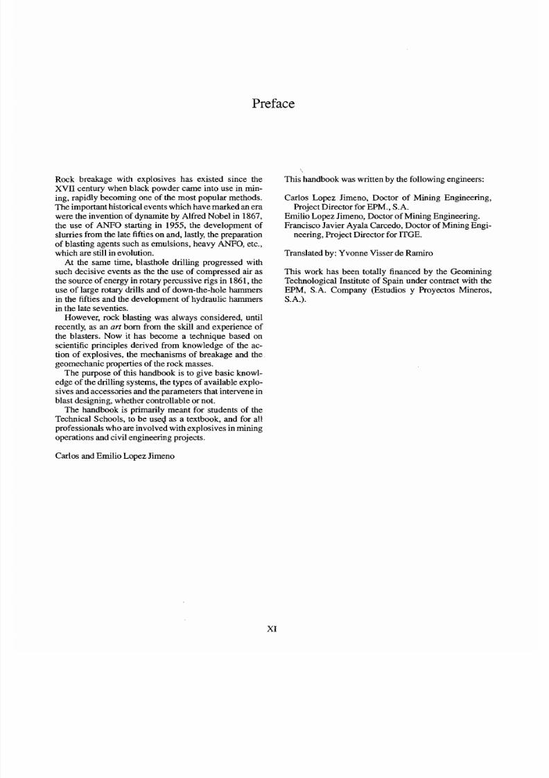
Rock breakage with explosives has existed since theXVII cen tury when black powder came into use in min-ing, rapidly becoming one of the most popular methods.The important historical events which have m arked an erawere the invention of dynamite by Alfred Nobel in 1867,
the use ofANFO
starting in 1955, the developm ent ofslu mes from the late fifties on and, lastly, the preparationof blasting agents such as emulsions, heavy ANFO, etc.,which are still in evolution.
At the Same time, blasthole drilling progressed withsuch decisive events as the the use of com pressed air asthe source of energy in rotary percussive rigs in 1861, theuse of larg e rotary drills and of down-the-h ole hammersin the fifties and the development of hydraulic hammersin the late seven ties.
However, rock blasting was always considered, untilrecently, as an ar t bom from the skill and experience ofthe blasters. Now it has become a technique based on
scientific principles derived from k nowledge of the ac-tion of explosives, the mechanisms of breakage and thegeomech anic properties of the rock m asses.
The purpose of this handbook is to give basic knowl-edge of the drilling Systems, the types of av ailab le explo-sives and accessaries and the Parameters that intervene inblast designing , whether controllable or not.
The handbook is primarily meant for studen ts of theTechnical Schools, to be useq as a textbook, and for allprofessionals who are involved with explosives in miningoperations and civil engineenng projects.
'
This handbook was written by the following engineers:
Carlos Lopez Jimeno, Doctor of Mining Engineering,Project Director for EPM., S.A.
Emilio Lopez Jim eno, Doctor of M ining Engineering.
Francisco Javier Ayala Carcedo, Doctor of Mining Engi-neering, Project Director for ITGE.
Translated by: Yvonne Visser de Ramiro
This work has been totally financed by the GeominingTechnological Institute of Spain under contract with theEPM, S.A. Company (Estudios y Proyectos Mineros,S.A.).
Carlos and Emilio Lopez Jimeno
7/28/2019 Drilling and Blasting in Rocks (sample)
http://slidepdf.com/reader/full/drilling-and-blasting-in-rocks-sample 10/81
Acknowledgements
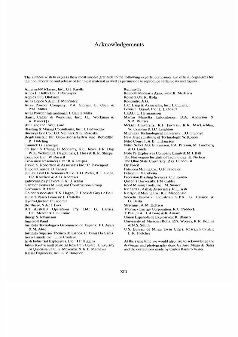
The authors wish to exp ress their mo st sincere gratitude to the following experts, com panies and official organisms fortheir collaboration and release of tech nical material as well as perm ission to reproduce certain data and figures.
Am erind-M ackissic, Inc.: G. J. Kno ttsAmos L . Dolby Co.: J. PetrunyakApp1ex:S.O. OlofssonAtlas Copco S.A.E.: E MenendezAtlas Powder Company: VA. Sterner, L. Osen &
PM . MillerAtlas Powd er International: J. Garcia M illaBauer, Calder & Workman, Inc.: J.L. Workman &
A. Bauer (T)
Bill Lane Inc.: W.C. LaneBlasting &Minin g Consultants, Inc.: J. Ludw iczakBucy rys Erie Co.: J.D. Nelma rk & G. RekoskeBendesanstalt für Geowissenschaften und Rohstdffe:
R. LüdelingCanmet: G. Larocque
Ci1 Inc.: S. Chung, B. Mohanty, K.C. Joyce, PR. Day,W.K. Webster, D. Dayphina is, I. Huss & K.R. Sharpe
Com inco Ltd.: W Russe11Crow snest Resources Ltd.: R.A. R eipasDavid , S. Robertson & Assoc iates Inc.: C. DavenportDupo nt Canada: D. TanseyE. I. Du Pont De Nem ours& Co.: P D. Porter, B. L. Glenn ,
J. R. Knudson & A. B. AndrewsEntrecan ales y Tavora, S.A.: J. AznarGardner Denver Mining and konstruction GroupGeovanca: R. UcarGolde r Associates: T.N. Hagan, E. Hoek & Guy Le BellHullera Vasco Leonesa: E. C astellsHydro-Quebec: F LacomteIberd uero , S.A.: J. ForaICI Australia Operations Pty Ltd.: G. Harries,
J. K. Mercer& G.G. PaineIlmeg: S. Johanss onIngersoll RandInstituto Tecnologico Geominero de Espaiia: E J. Ayala& M. Abad
Instituto Superior Tecnico de Lisboa: C . Dinis Da GamaIreco Can ada Inc.: L. de CouteurIrish Industrial Explosives, Ltd.: J. P Higg insJulius Kruttschnitt Mineral Research Centre, University
of Quee nsland: C. K. Mc kenzie& K. E. MathewsKaiser Eng ineers, Inc.: G.V. Borqu ez
Kemira OyKenneth Mede aris Associates: K. Med earisKometa Oy: R. IkolaKontinitro A.G.L.C. Lang & Assoc iates, Inc.: L.C.LangLew is L. Oriard, Inc.: L .L.OriardLKAB: L. HermanssonMartin Marietta Laboratories: D.A. Anderson &
S. R. WinzerMcGill University: R.E Favreau, R.R. MacLachlan,
W. Comeau & J.C. Leighto nMich igan Techno logical Unive rsity: F.O. O tuonyeNew Jersey Institu te of Technology: W. KononNitro Consu lt, A.B.: I. HanssonNitro Nobel AB: B. Larsson, PA . Persson, M. Landberg
& G. LandeNobe l's Explo sives Company Lim ited: M. J. BallThe Norwegian Institute of T echnology: K. NielsenThe Ohio State University: R.G. LundquistOy ForcitPalabora Mining Co.: G . P FauquierPetromin: \!CobeiiaPrecision Blasting S ervices: C.J. KonyaQue en's U niversity: P N. Calde rReed M ining Tools, Inc.: M. SuiirezRichard L. Ash & Assoc iates: R. L. AshRietspru it Mining Co.: K. I. Macdo naldSocieta Esplosivi Industriali S.PA.: G. Calarco &
G. BertaStrornrne : A. M. HeltzenThermex Energy Corporation: R.C. Paddock
T Peal, S.A.: J. Alonso & R.ArnaizUnion Espaiiola de Explosivos: R. BlancoUniv ersity of Misso uri Rolla: P N. Worsey, R. R. Rollins& N.S. Smith
U.S. Bureau of Mines Twin Cities. Research Center:L. R. Fletcher
At the Same time we would also like to acknow ledge thedrawings and photography done by Jose Maria de Salas
and the corrections mad e by Carlos Ram iro Visser.
7/28/2019 Drilling and Blasting in Rocks (sample)
http://slidepdf.com/reader/full/drilling-and-blasting-in-rocks-sample 11/81
CHAPTER 1
Rock drilling methods
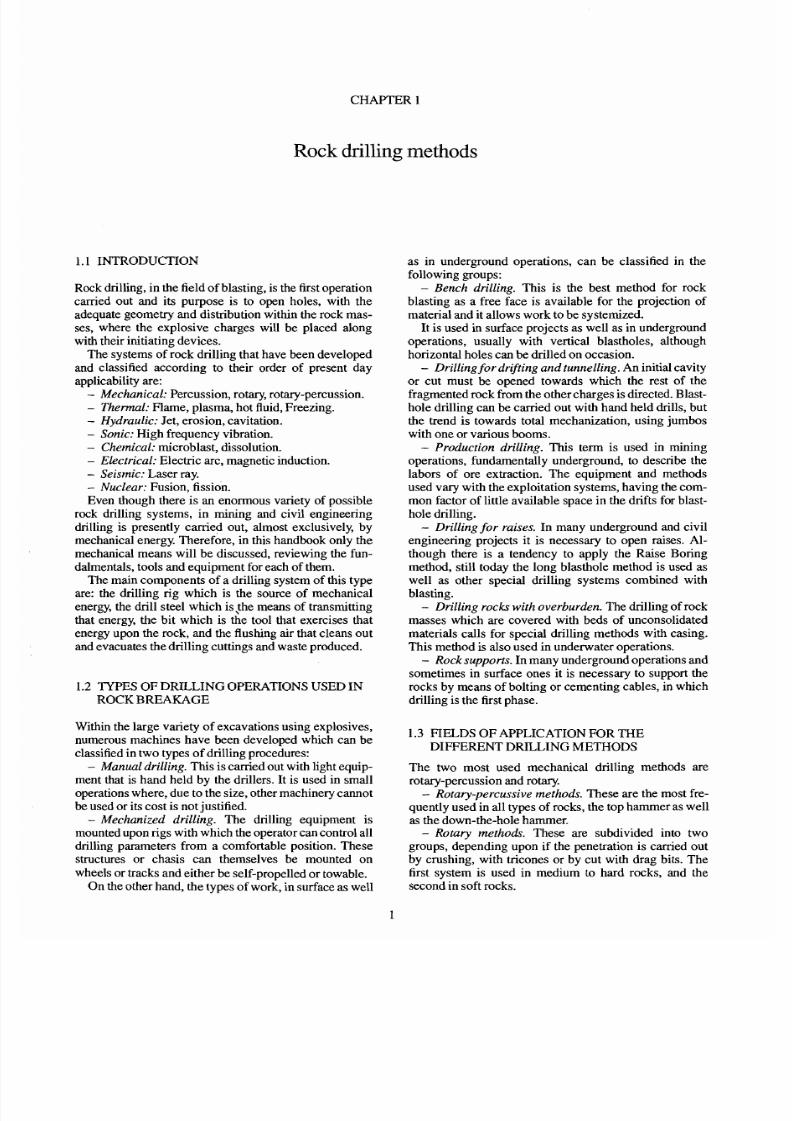
1.1 INTRODUCTION
Rock drilling, in the field of blasting, is the first operation
carried out and its purpose is to Open holes, with the
adequate geometry and distribution within the rock mas-
ses, where the explosive charges will be placed alongwith their initiating devices.
The systems of rock drilling that have been developed
and classified according to their order of present day
applicability are:- Mechanical: Percussion, rotary, rotary-percussion.- Themzal: Flame, plasma, hot fluid, Freezing.- Hydraulic: Jet, erosion, cavitation.- Sonic: High frequency vibration.- Chemical: microblast, dissolution.- Electrical: Electric arc, magnetic induction.- Seismic: Laser ray.- Nuclear: Fusion, fission.
Even though there is an enormous variety of possible
rock drilling systems, in mining and civil engineering
drilling is presently canied out, almost exclusively, by
mechanical energy. Therefore, in this handbook only the
mechanical means will be discussed, reviewing the fun-
dalmentals, tools and equipment for each of them.
The main components of a drilling system of this type
are: the drilling rig which is the source of mechanical
energy, the drill steel which is,the means of transmitting
that energy, the bit which is the tool that exercises that
energy upon the rock, and the flushing air that cleans out
and evacuates the drilling cuttings and waste produced.
1.2 TYPES OF DRILLING OPERATIONS USED IN
ROCK BREAKAGE
Within the large variety of excavations using explosives,
numerous machines have been developed which can be
classified in two types of drilling procedures:- Manual drillin g. This is canied out with light equip-
ment that is hand held by the drillers. It is used in small
operations where, due to the size, other machinery cannot
be used or its cost is not justified.- Mechanized drilling. The drilling equipment is
mounted upon rigs with which the Operator can control all
drilling Parameters from a comfortable position. These
structures or chasis can themselves be mounted on
wheels or tracks and either be self-propelled or towable.
On the other hand, the types of work, in surface as well
as in underground operations, can be classified in the
following groups:- Bench drilling. This is the best method for rock
blasting as a free face is available for the projection of
material and it allows work tobe systemized.
It is used in surface projects as well as in undergroundoperations, usually with vertical blastholes, although
horizontal holes can be drilled on occasion.- Drilling fordrifting and tunnelling. An initial cavity
or cut must be opened towards which the rest of the
fragmented rock from the other charges is directed. Blast-
hole drilling can be carried out with hand held drills, but
the trend is towards total mechanization, using jumbos
with one or various booms.- Production drilling. This term is used in rnining
operations, fundamentally underground, to describe the
labors of ore extraction. The equipment and methods
used vaq with the exploitation systems, having the com-
mon factor of little available space in the drifts for blast-
hole drilling.- Drilling for raises. In many underground and civil
engineering projects it is necessary to Open raises. Al-
though there is a tendency to apply the Raise Bonng
method, still today the long blasthole method is used as
well as other special drilling systems combined with
blasting.- Drilling rocks with overburden. The drilling of rock
masses which are covered with beds of unconsolidated
materials calls for special drilling methods with casing.
This method is also used in underwater operations.
- Rock supports. In many underground operations andsometimes in surface ones it is necessary to support the
rocks by means of bolting or cementing cables, in which
drilling is the first phase.
1.3 FiELDS OF APPLICATION FOR THEDIFFERENT DRILLING METHODS
The two most used mechanical drilling methods are
rotary-percussion and rotary.- Rotary-percussive methods. These are the most fre-
quently used in all types of rocks, the top harnrner as well
as the down-the-hole hammer.- Rotary methods. These are subdivided into two
groups, depending upon if the penetration is canied out
by crushing, with tricones or by cut with drag bits. The
first system is used in medium to hard rocks, and the
second in soft rocks.
7/28/2019 Drilling and Blasting in Rocks (sample)
http://slidepdf.com/reader/full/drilling-and-blasting-in-rocks-sample 12/81
2 Drilling and blas ing of rocks
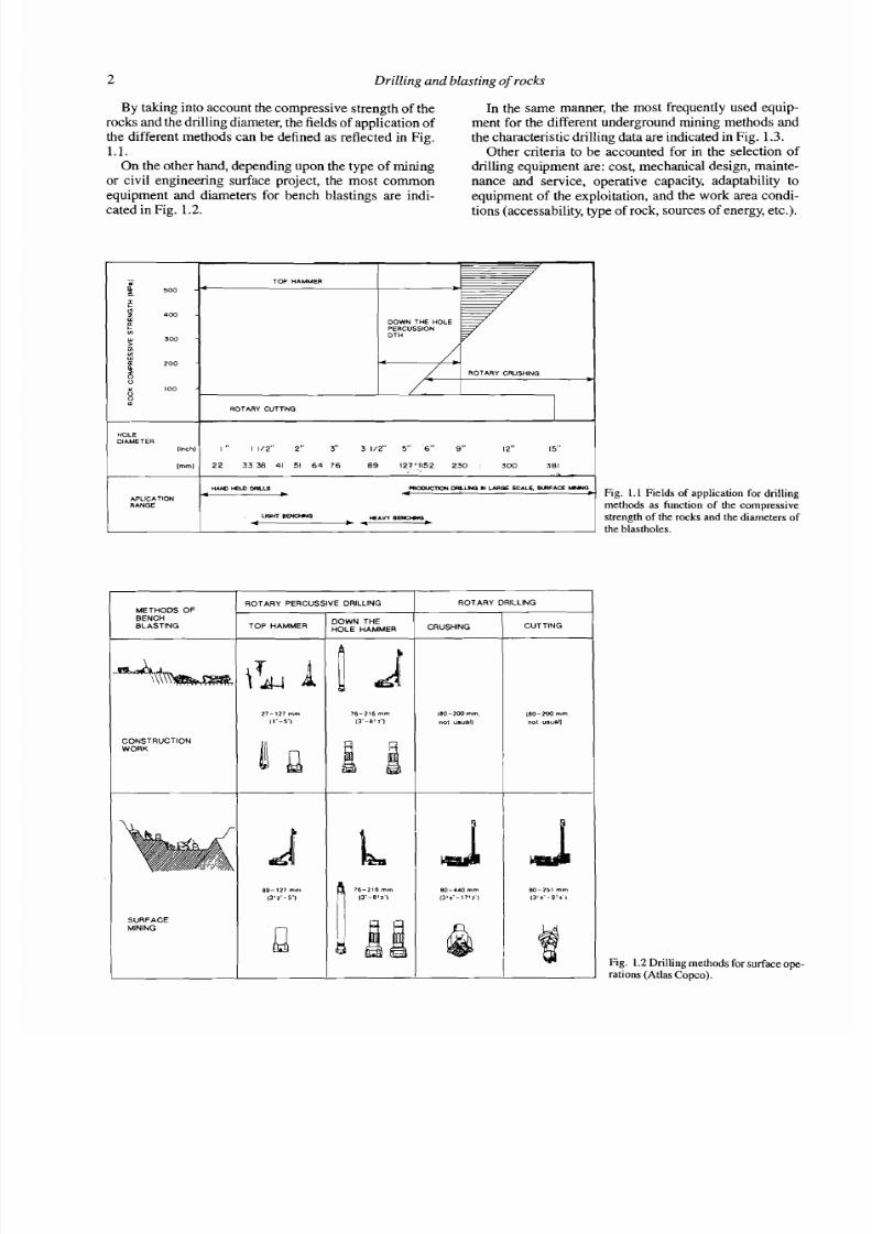
By taking into account the compressive strength of therock s and the drilling diam eter, the fields of application of
the different methods can be defined as refiected in F ig.
1 . 1 .
On the other hand, depending upon the type of m ining
or civil engineenng surface project, the most comrnonequipment and diameters for bench blastings are indi-
cated in Fig. 1.2.
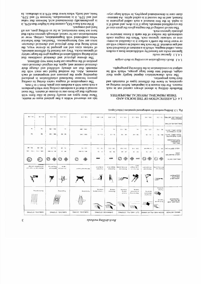
In the Same manner, the most frequently used equip-
ment for the different underground mining method s andthe characten stic drilling data are indicated in Fig. 1.3.
Other criteria to be accounted for in the selection of
drilling equipm ent are: cost, mechanical design, m ainte-
nance and semice, operative capacity, adaptability toequipment of the exploitation, and the work area condi-
tions (accessability, type of rock, sources of energy , etc.).
DOWN TUE HOLE
HUO HEL0 DRLLS
APLlCATlONRANGE
DIAMETERI "OLE
(Inch)
mOOUCTIOH.-1HO N 1mGE SCUE. W A C EWFig. 1 . 1 Fields of application for drilling
methods as function of the compressive
I " 11/2" 2" 3" 3 1/2" 5" 6" 9,' 12" 15" I
METHODS OF
BENCHBLASTING
L
1 ROTARY PERCUSSIVE DRILLING I ROTARY DRILLING I
L W E HEAW B
4 Wstrength of the m cks and the diameters of
the blastholes.
DOWN THE1 1 HOLE HAMMER I CRUSHING 1 CUTTMG I
CONSTRUCTION
WORK
SURFACEMlNlNG
I
180-200 mm
no t "."aI)
(80-200 mm .
no t "sunll
Fig. 1.2 Drilling methods for surface ope-rations (Atlas Copc o).
7/28/2019 Drilling and Blasting in Rocks (sample)
http://slidepdf.com/reader/full/drilling-and-blasting-in-rocks-sample 13/81
U1 '3!WqEflIil S! J! U B q 1aMOl UaqM fCllsI?lPUE '3!s~q'%ZSpue SV uaaMiaq 'ale!paw alu! s! I! '%ZSPUB pueanleA ieql uaarnlaq ' p 1 3 ~ aleuyuiouap A1le3p1aq3oa8 s!
I! '%z9 ueqi ~aq8 rq! leqliuaiuo3zo!~seq 3301aq i j I-13eduio3pue pn q
~ l e n sao8 8u!lp.q se nj SE 'pazuoa~aui aaq 1ou aAeq1eql s y m ~noaug! q8noqile f p a p ~q ue3 uoyiezuoalauiJO naM '8uyin3 'uo!ieiuaui8eg q i ! ~ aiuoquo3 uaqM
JoIAeqaq qaq i 'aJojaJaqjd -snoau a8o~ alaqJ ~ A
n s3!is!- ~ a i ~ n q 3e 3 y a q 3 p m 1e3!sAqd lyaql l e q %u!aq iInsaJaql 'SLBM aslaA!p U! padn o~8 n pue sazrs snop A jo' s l e ~ a u yua~ajj!pAq p a w o j a n A a q ~s y 3 0 ~noau81 O
A l a p ~% n l qi a ~ !8 ur8 eui jo uo!ie3y!pqos 8u unp lsyxaieql suog!puo3 1e3!uiaq3 pue 1eqsAqd asJaA!p aq L
-ma~ajj!p r a ~aaq aAeq ue3 seu i8e ui aq l jo uo!i!sod- u o 3 le3 ya q 3 leuy8uo aql 'upA3e 'pue lualuo3 le 3y aq 3~!aq)a8u eq3 p m pay!p!Ios Ap ea~ lea n l eq l s l e la u yaqi q i ! ~ 3ea-r ue3 prnbg lenp!saJ aqi 'o sl v wau iou iq3ea jo a~ nle~ adw alu e a ~ n s s a ~ dqi uodn Ourpuadappa3npo~ds! uopez!lle1su3 pauo!13eq a sn w aq ssa 3o ~d8~11003I! 8uunp sa pA eui8eui jo uog!soduio~ aqL
.unu 5 01 I w o ~ j ~ ~ 1 8z!s uinypaui E q i ! ~seui 3301esa3npo~d 3 y ~w!] 8u!loo3 aieJap oui e jo 1 eq s! p uu oulsoui aqL .sJaiaui jo suazo p 01 auo uioq 08 ieqi sq8 ua ~ls
q i ! ~ uoj aI!p U punoj Alpnsn a n sadAi aaJqi asaqL.xuieui 10 ss eui pau.18 auy e U!~I!M pahiasqo a n sp1
- s h 3 a 8 ~e l 3 q ~! 'hrqAdiod paieu!wouap s! ase3 aiw p-a w al u! u v 'aiqd e palle3 s! i! puo3as aqi U! p m ' p a w o js! al!ieui8ad palp3 3301 e a3mlsu! i s ~ y ql UI .p!de~s!l! J! lleuis pue '~ 0 1 s! q j! a8 nl fs le~ aup I az!~le]shr~qijo azrs u ~ 1 8ql eui8e w aql jo 8u!loo3jo aleJ aqL
-330~noau813!uoinldJO aA!sniiu! s m o j 11 V a q o a ~ e p n s qi qieawapuns loo3 eu i8eu i aq i u a m .y3o ~ noau81 ~ F E ~ I O AO aA!s
-rulxa se pay!ssep s! q a ~ e p n s,q m a aq l ur013 JaleM JOJ? qirm I ~ E I U O ~! paloo 3 si3q 3301aq ljI -1euaieuisi38 pue3301paAloss!pjo a ~ n l x y s! q 3 !q ~ eui8eui palle3 'ssewuaqoui e w o g uo!le3g!p!los Aq p a w o j a n s y 3 o ~noau81
q 3 0 ~noauzj 1 1 9-
- s q d e ~ 8 e n dU!MOIIOJ aql U! uo!~e~ap!suo 3 i i3arqnsaq II!M q 3 q ~sd no ~ 8 8 n l aaJql olu! pap!A!p 'u!8uo1!aqi uodn Ala8n1 puadap s3 ps ua l~ en q 33301 aq L
.sa!vado~d3!seq qaqlpue s leualeu i jo sadAl ~ua~a j j !p q ~ o u y1 'uo!le~ado
ue 8u!mls aJojaq '~uevodh!! 11 uoseaJ s!ql ~ o gsassew3301 U! ino p a y 3 s A e ~ ~ esouile SI 8u!llup aloqlsela
SBILXEldOXd 7V3ISA Hd 7 Vd I3N Iüd M BHLCINV SX 30X BH L d0 NOILV3HISSV73 9'1
5 1 - 5 1 S Z - S I C L - B i 6 0 - 1 0 6 0 - 1 0 P I - 0 1 L I - 6 0 0 9 - o c o ~ - ~ i 1 3 ~ ~ ~ ~ a 3 1 1 1 8 a ~
N 0 1 1 3 ~ O O t
O N I l S V l 8 - 3 N l 1 l l H 8
m c - 0. !3 l l l lV H O A H H l l N
OS 05
I1 3 3 N V W H O j H 3 d
ILN3WdlnO3
D N l l l l t l O
I I I
SL - Si O 5 ,
1-91 IS - B Y 0~ - m~ LU: ar("J4
n313wv10 3101-
V I V 0 3 N l l l l 8 0
I
l N 3 W d l n 0 3
b i i , , l ' D bi."
I,
3 n O i N H 3 3 1
. w f i.8,,00
O N I L S V l 8
0 N V O N l l l l 8 O
-.
7/28/2019 Drilling and Blasting in Rocks (sample)
http://slidepdf.com/reader/full/drilling-and-blasting-in-rocks-sample 14/81
4 Drilling and blasting of rocks
the same sense that igneous rocks are poorer in silica,they are richer in ferromagnesian silicates. The acids aremore abrasive and harder than the basic ones, but they arealso more dense and resistant to impact.
1.4.1.2 Metamorphic rocksMetamorphic rocks are derived from other pre-existingendogenic or exogenic rocks through important transfor-mations of their mineral components. These markedchanges are produced by the necessity of stabilizing theirminerals under the new conditions of temperature, pres-sure and chemism.
These rocks are intermediate in physicai and chemicalcharacteristics, between the igneous and the sedimentary,because they have associations of minerais that pertain tothe two types. Thus, minerals such as quartz, feldspars,rnicas, amphiboles, and olivines, essential in igneous
rocks, are also found in metamorphic rocks; howeverthey do not contain aikali feldspars. As in sedimentaryrocks, they can have calcite, dolomite, silica and he-matites; but they do not contain evaporites. Mineralscomrnon to the two other types also appear such astourmaline, zircon, magnetite, topaz and corundum; all ofwhich are very stable in any exogenous or endogenousmedium.
There is a series of minerals that are very specific tometamorphic rocks, which can form part of the grains ofdetrital rocks, owing to their stability in exogenous me-dium~,nd others are at the same time products of meteo-ric alteration of the minerals in endogenic rocks. Actually,
meteorization is a mineralogical transformation that isboth a physical and chemical process, but at low tempera-ture and pressure.
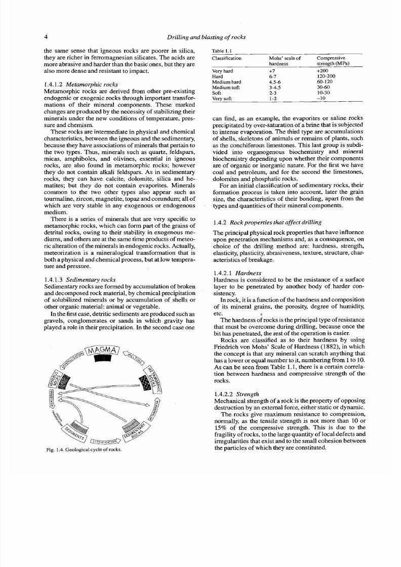
1.4.1.3 Sedimentary rocksSedimentary rocks are formed by accumulation of brokenand decomposed rock material, by chemical precipitationof solubilized minerals or by accumulation of shells orother organic material: animal or vegetable.
In the first case, detritic sediments are produced such asgravels, conglomerates or sands in which gravity hasplayed a role in their precipitation. In the second case one
Fig. 1.4. Geological cycle of rocks.
Table 1.1
Classification Mohs' scale of Compressivehardness strength(MPa)
Very hard +7 +200Hard 6-7 120-200
Medium hard 4.5-6 60- 120Medium soft 3-4.5 30-60Soft 2-3 10-30
Very soft 1-2 -10
can find, as an example, the evaporites or saline rocksprecipitated by over-saturation of a brine that is subjectedto intense evaporation. The third type are accumulationsof shells, skeletons of animals or remains of plants, suchas the conchiferous limestones. This last group is subdi-vided into organogenous biochemistry and mineralbiochemistry depending upon whether their components
are of organic or inorganic nature. For the first we havecoal and petroleum, and for the second the limestones,dolornites and phosphatic rocks.
For an initial classification of sedimentary rocks, theirformation process is taken into account, later the grainsize, the characteristics of their bonding, apart from thetypes and quantities of their rninerai components.
1.4.2 Rock properties that affect drilling
The principal physical rock properties that have influenceupon penetration mechanisms and, as a consequence, onchoice of the drilling method are: hardness, strength,
elasticity, plasticity, abrasiveness, texture, structure, char-acteristics of breakage.
1.4.2.1 HardnessHardness is considered to be the resistance of a surfacelayer to be penetrated by another body of harder con-sistency.
In rock, it is a function of the hardness and compositionof its mineral grains, the porosity, degree of humidity,etc. E
The hardness of rocks is the principal type of resistancethat must be overcome during drilling, because once the
bit has penetrated, the rest of the operation is easier.Rocks are classified as to their hardness by usingFriedrich von Mohs' Scale of Hardness (1882), in whichthe concept is that any mineral can scratch anything thathas a lower or equai number to it, numbering from 1 to 10.As can be seen from Table 1.1, there is a certain correla-tion between hardness and compressive strength of therocks.
1.4.2.2 StrengthMechanical strength of a rock is the property of opposingdestruction by an extemal force, either static or dynarnic.
The rocks give maximum resistance to compression,
normally, as the tensile strength is not more than 10 or15% of the compressive strength. This is due to thefragility of rocks, to the large quantity of local defects andirregularities that exist and to the small cohesion betweenthe particles of which they are constituted.

7/28/2019 Drilling and Blasting in Rocks (sample)
http://slidepdf.com/reader/full/drilling-and-blasting-in-rocks-sample 15/81
Rock drilling rnethods 5
The rock strength fundam entally depends on its mine-ralogical composition. Among the integrating minerals,quartz is the mo st solid with a strength that goes over 500MPa, w hile that of the ferromagnesian silicates and thealuminosilicates vary between 20 0 and 500 MP a, and thatof calcite from 10 to 20 M Pa. Th erefore, the higher the
quartz content, the mo re the strength increases.The mineral strength depends upon the size of the
crystals and diminishes with their increase. Thisinfluence is significative when the cry stal size is under 0.5mm .
In rocks, the size factor has less influence on strengthas the intercry stalline cohesio n force also intervenes. Forexample, the compressive strength of a fine grainedarkose sandstone is almost double that of a coarsegrained; that of marble composed of 1 rnrn graines isequal to 100 MP a, whereas a fine grained limes tone- to4 mm - as a strength of 200 to 250 M Pa.
Amo ngst the sedim entary rocks the ones with higheststrength are those that contain silica cement. With thepresence of clay cement, the strength is drasticallyreduced.
Porosity in roc ks with the Same lithology also reducesstrength proportionately, more po rosity- ess streng th; asit simultaneously reduces the number of contacts of themineral particles and the force of reciprocal action be-tween them.
The depth at w hich rocks were forme d arid the degreeof metam orphism also have influence upon their strength.Therefore, the strength of clay beddings near the groun dsurface can be of 2 to 10 MP a, whereas in clay rocks that
went through a certain metamorphism the strengths canreach 50 to 100 MPa.
On the other hand, the strength of ansiotropic rocksdepends upon the sense of action of the force. The com-pressive strength of rocks in the perpendicular to
stratification sense or schistosity is larger than in a paral-lel sense. The q uotient that is usually ob tained betweenboth strength values varies between 0.3 and 0.8, and it isequal to 1 only for isotropic rocks.
In Fig. 1.5, the most frequent compressive strengths
for different types of rock are indicated.
1.4.2.3 Elasticity
The majonty of rock minerals have an elastic-fragilebehavior, which obeys the Law of Hooke, and are des-troyed w hen the strains exceed the limit of elasticity.
Depending upon the nature of de forma tion, as functionof the Stresses produ ced by sta tic charges, three groups ofrocks are taken into con sideration: 1) The elastic-fragileor those which obey the Law of Hooke, 2) The plastic-fragile, that hav e plastic deformation before destruction,3) The highly plastic or very po rous, in which the elastic
deformation is insignificant.The elas tic properties of rocks are characte nzed by theelasticity m odule 'E' and the Poisson coefficient ' V ' . Th eelasticity modu le is the proportionality factor between thenormal Stress in the rock and the relative correspondantdeform ation, its value in most rocks varies between 0 .03X 104 and 1.7 X 1o5 MP a, basically depending upon themineralogical comp osition, porosity, type of deformationand magnitud of the applied force.
The values of the elasticity modules in the majority ofsedimentary rocks are lower than those corresponding tothe minerals in their com position. The texture of the rockalso has influ ence on this Parameter, as the elasticity
module in the direction of the bedding or schistosity isusually larger than when perpendicular.
Poisson's coefficient is the factor of proportionalitybetween the relative longitudinal deformations and thetransversal deformations. For m ost rocks and minerals itis between 0.2 and 0.4, and only in quartz is it abnon nallylow, aroun d 0.07.
0 I 0 20 30 40 60 SO
DEFORMATION (mm x 108)
Fig. 1.6.Curves of stress-deformation or different types of rocks.
7/28/2019 Drilling and Blasting in Rocks (sample)
http://slidepdf.com/reader/full/drilling-and-blasting-in-rocks-sample 16/81
6 Drilling und blasting of rocks
1.4.2.4 PlasticityAs indicated before, in some rocks the plastic deforma-
tion preceeds destruction. This begins when the Stresses
exceed the limit of elasticity. In the case of an ideally
plastic body, that deformation is developed with an inva-
riable stress. Real rocks are deformed and consolidated at
the Same time: in order to increase the plastic deformation
it is necessary to increase the effort.
The plasticity depends upon the mineral composition
of the rocks and diminishes with an increase in quartz
content, feldspar and other hard minerals. The humid
clays and some homogeneous rocks have plastic proper-
ties.
The plasticity of the stony rocks (granites, schistoses,
crystallines and sandstones) becomes noticeable
especially at high temperatures.
1.4.2.5 AbrasivenessAbrasiveness is the capacity of the rocks to wear away the
contact surface of another body that is harder, in the
rubbing or abrasive process during movement.
The factors that enhance abrasive capacities of rocks
are the following:
- The hardness of the grains of the rock. The rocks
that contain quartz grains are highly abrasive.
- The shape of the grains. Those that are angular are
more abrasive than the round ones.
- The size of the grains.
- The porosity of the rock. It gives rough contact
surfaces with local stress concentrations.- The heterogeneity. Polymineral rocks, although
these are equally hard, are more abrasive because they
leave rough surfaces with hard grains as, for exarnple,
quartz grains in a granite.
This property has great influence upon the life of drill
steel and bits.
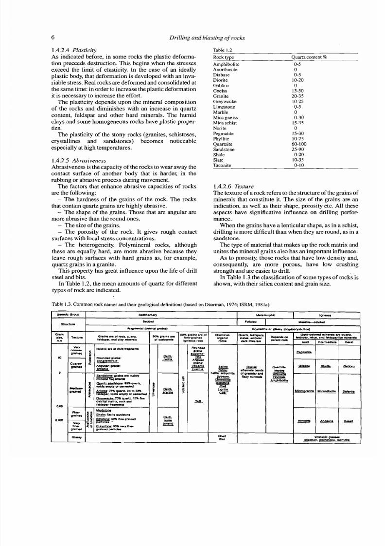
In Table 1.2, the mean arnounts of quartz for different
types of rock are indicated.
Table 1.2
Rock ype Quartz content %
Amphibolite
AnorthositeDiabase
DioriteGabbroGneiss
Granite
Greywacke
Limestone
MarbleMica gneissMica schist
Nori te
Pegmatite
PhylliteQuartzite
Sandstone
Shale
SlateTaconi e
1.4.2.6 TextureThe texture of a rock refers to the structure of the grains of
minerals that constitute it. The size of the grains are an
indication, as well as their shape, porosity etc. All these
aspects have significative influence on drilling perfor-
mance.
When the grains have a lenticular shape, as in a schist,
drilling is more difficult than when they are round, as in a
sandstone.
The type of material that makes up the rock matrix and
unites the mineral grains also has an important influence.
As to porosity, those rocks that have low density and,
consequently, are more porous, have low crushing
strength and are easier to drill.
In Table 1.3 the classification of some types of rocks is
shown, with their silica content and grain size.
Table 1.3. Cornmon rock names and their geological definitions (based on Dearm an, 1974; SRM, 198la).
W k rw p
m n
s.dh.mY Wtamorphk I Ign-
Ba4d.d F U i M
C ~ I U I -
mcLs
Sdlne
h.lll&~hydrlta.
c n ~
Chml
nlnt
OnlnQralm srr oi ra k qurm..In' T*minIaldipu. and sl.y mlmu
mm
V W Gnlna arr oi mcL ir.pmnti
M
M8uhrJOhl l .d
G l o r l
60* anIn* anO' uttonar*
rudlls
2 .
&M. ~ d i p . nmw .dcuhrdrrk mlmnh
Omln:
. n - T w ~oi p r u u l u a d
n i i ; y d m
Fr.pmnid (d.mW ~ n l n i )
60% onlns ui 1fintgrrlnedIpneau. rock
G n b a ZJ~ . 15%n~a d k i id1midap.r mpmu
om
S(itstrns:50* nncpnlind0
f i r n z o CI. o n s o r ~ n ~praind *drnd"
QR~&
Cryniillnr or o l y ~ l l l n )
Volunk 0lP.r:ob.idin. pltchslo(~. rhyutr
D9ndiP'mt -
o-
C i 2
lall*(üi.L)
m " ~ p n i m :bmala
pndnon:gnh r inmJnPlm l w d h.prnrm
fl0und.dprslna:T
~ Z a rgralm:
voIc.nIs
I b'"'
-.un
AJk .7HlWWU,UPl02YS
~ p l r , r o ~ r n p t y a s m ~
uorit-mhd mim rb inq u ak l d s w .da.
w d
B-
M a
~ m i i b
in d Iak&mdIkm
lnt.m.dim
E
Mlcmdlcdiok-lt.
m l n n h
8.lk
DOM.
7/28/2019 Drilling and Blasting in Rocks (sample)
http://slidepdf.com/reader/full/drilling-and-blasting-in-rocks-sample 17/81
Rock drilling methods 7
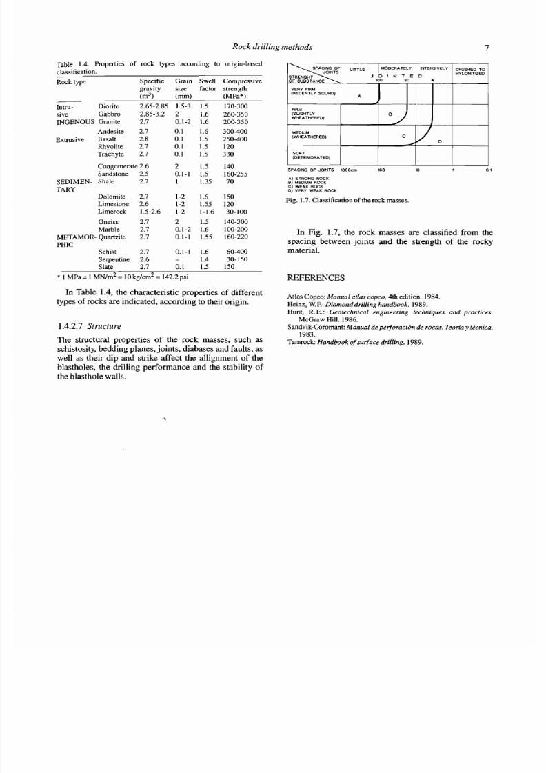
Table 1.4. Properties of rock types according to origin-based
classification.
Rock type Specific Grain Swell Compressivegravity size factor strength
(m3) (mm) (MPa*)
Tntru- Diorite 2.65-2.85 1.5-3 1.5 170-300.-.-
sive Gabbro 2.85-3.2 2
INGENOUS Granite 2.7 0.1-2
Andesite 2.7 0.1
Extrusive Basalt 2.8 0.1
Rhyolite 2.7 0.1
Trachyte 2.7 0.1
Congomerate 2.6 2
Sandstone 2.5 0.1-1
SEDIMEN- Shale 2.7 1
TARYDolomite 2.7 1-2
Limestone 2.6 1-2
Limerock 1.5-2.6 1-2
Gneiss 2.7 2
Marble 2.7 0.1-2
METAMOR- Quartzite 2.7 0.1-1
PHICSchist 2.7 0.1-L
Serpentine 2.6 -Slate 2.7 0. L
* 1 MPa = 1 MN/^^ = 10 kg/cm2 = 142.2 psi
In Table 1.4, the cha racteristic properties of differenttypes of rocks are indic ated, according to their origin.
1.4.2.7 Structure
The stmctural properties of the rock masses, such asschistosity, bedding planes, joints, diabases and faults, aswell as their dip and strike affect the allignment of theblastholes, the drilling performance and the stability ofthe blastho le walls.
SPACING OF JOINTS lOOOcm 105 10 1 0.1
A) STRONG ROCKB) MEDIUM ROCKC) WEAK ROCKD) VERY WEAK ROCK
Fig. 1.7. Classification of the rock masses.
In Fig. 1.7, the rock masses are classified from thespacing between joints and the strength of the r o c hmaterial.
REFERENCES
Atlas Copco: Manual atlas copco, 4th edition. 1984.
Heinz, W.F.: Diamond drilling handboo k. 1989.
Hunt, R.E.: Geotechnical engineeßng techniques und pracdces.
McGraw Hill. 1986.
Sandvik-Coromant:Manual de perforacibn de ro cas. Teoriay tkcnica.
1983.
Tamrock: Handbook of surface drilling. 1989.
7/28/2019 Drilling and Blasting in Rocks (sample)
http://slidepdf.com/reader/full/drilling-and-blasting-in-rocks-sample 18/81
CHAPTER 2
Rotary percussive diilling
2.1 INTRODUCTION
Drilling by rotary percussion is the most classic system
for drilling blastholes, and its chronological appearance
coincides with the industrial development of the nin-
teenth century. The first Prototype machines made bySinger (1838) and Couch (1848) were run by steam, but it
was when compressed air was used as the source of
energy, in the execution of the tunnel of Mont Cenis in
1861, that this system evolved and was put into extensive
use. This event, along with the arrival of dynamite, was
decisive in the rapid development of rock breakage in
mining and civil engineering at the end of the last cen-
t ury.
The drilling pnnciple of these rigs is based upon the
impact of a steel piece (piston) that hits a utensil which
transrnits at the Same time that energy to the bottom of the
blasthole by means of the final element called the bit. The
rotary percussive rigs are classified in two large groups,
depending upon where the hammer is located:- Top hammer.In these drills, two of the basic actions,
rotation and percussion, are produced outside the blast-
hole, and are transmitted by the shank adaptor and the
dnll steel to the dnll bit. The hamrners can be driven
hydraulically or pneumatically.- Down the hole hammer.The percussion is delivered
directly to the drill bit, whereas the rotation is performed
outside the hole. The piston is driven pneumatically,
while the rotation can be hydraulic or pneumatic.
Depending upon the fields of application of these
drilling ngs, surface or underground, the most comrnonrange of diameters are shown in Table 2.1.
The main advantages of rotary percussive dnlling are:- It can be applied to any type of rock, from soft to
hard.- Wide range of diameters;- Versatile equipment, it adapts well to different ope-
rations and is very Mobile;- Only requires one Operator;- Easy, quick maintenance, and- The capital cost is not high.
In view of these advantages and characteristics, the
type of operations where it is used are:- Underground civil engineering; tunnels, under-
ground hydraulic plants, residual deposits, etc., and in
surface operations; roads, highways, indusirial excava-
tions, etc.
- In underground mines and in small to medium sized
surface operations.
2.2 FUNDAMENTALS OF ROTARY PERCUSSIVE
DRILLING
Rotary percussion drilling is based upon the combination
of the following:- Percussion. The impacts produced by repeated
blows of the piston generate shock waves that are tran-
smitted to the bit through the drill steel (in top harnmer) or
directly upon it (down the hole).- Rotation. With this movement, the bit is turned so
that the impacts are produced on the rock in different
positions.- Feed, or thrust load. In order to maintain the contact
of the dnll bit with the rock, a thrust load or feed force is
applied to the drill siring.- Flushing. aushing removes the drill cuttings from
the blasthole.
The indentation forming process with which penetra-
tion is achieved in this drilling system is divided into five
times, as indicated in Fig. 2.2.
a) Crushing of the rough edges of the rock upon bit
contact.
b) Radial cracks appear from the points of Stress con-
centration and aV shaped wedge is formed.
C) The rock of the wedge is pulverized.
d) The larger fragments are chipped in the zones next
to the wedge.e) The drill cuttings are flushed away.
This sequence repeats itself with the Same impact
rhythrn of the piston upon the system of energy transmis-
sion to the bit.
The yield of this process increases proportionally with
the size of the rock chippings.
2.2.1 Percussion
The kinetic energy E, of the piston is transmitted from the
hammer to the drill bit, through the dnll steel, in the form
of a shock wave. The wave travels at high speed and its
shape depends basically on the design of the piston.
When the shock wave reaches the drill bit, part of the
energy is transformed into work, causing the bit to pene-
trate, and the rest is reflected and returns through the drill
steel. The efficiency of this transmission is difficult to
7/28/2019 Drilling and Blasting in Rocks (sample)
http://slidepdf.com/reader/full/drilling-and-blasting-in-rocks-sample 19/81
Rotary percussive drilling
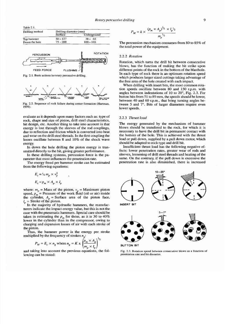
Tahle 2.1 .
Drilling method Drilling diameter (mm)Surface Underground
Top hammer 5 0- 127 38- 65Down the hole 75 -2 00 100- 165
ROTATION
FEED FORCE
Fig. 2. 1. Basic actions in rotary percussive drilling.
Fig. 2.2. Sequence of rock failure during Center formation (Hartman,
1959).
evaluate as it depends upon many factors such as: type ofrock, shape and size of piston, drill steel characteristics,bit design, etc. Another thing to take into account is thatenergy is lost through the sleeves of the rod couplings,due to reflection and fricton which is converted into heatand wear on the drill steel threads. In the first coupling thelosses oscillate between 8 and 10%of the shock wave
energy.In down the hole drilling the piston energy is tran-
srnitted directly to the bit, giving greater performance.In these drilling Systems, percussion force is the pa-
rameter that most influences the penetration rate.The energy freed per hammer stroke can be estimated
from the following equations:
where: m, = Mass of the piston, V = Maximum pistonspeed,p, = Pressure of the work ffuid (oil or air) insidethe cylinder, A, = Surface area of the piston face,I, = Stroke of the piston.
In the majority of hydraulic hammers, the manufac-turers indicate the impact energy value, but this is not thecase with the pneumatic hammers. Special care should betaken in estimating the p, for these, as it is 30 to 40%
lower in the cylinder than in the compressor, owing tocharging and expansion losses of air with each stroke ofthe piston.
Thus, the hamrner power is the energy per strokemultiplied by the frequency of strokesn,:
. .and taking into account the previous equations, the fol-
lowing can be stated:
The percussion mechanism consumes from 80 to 85%of
the total power of the equipment.
2.2.2 Rotation
Rotation, which tums the dnll bit between consecutiveblows, has the function of making the bit stnke upondifferent points of the rock in the bottom of the blasthole.In each type of rock there is an optimum rotation speedwhich produces larger sized cuttings taking advantage of
the free area of the hole created with each impact.When drilling with insert bits, the most common rota-
tion speeds oscillate between 80 and 150 r.p.m. withangles between indentations of 10 to 20°, Fig. 2.3. For
button bits from51 to 89mm, the speeds should be lower,between 40 and 60 r.p.m., that bring turning angles be-tween 5 and 7". Bits of larger diameters require evenlower speeds.
2.2.3 Thrust load
The energy generated by the mechanism of hammerblows should be transfered to the rock, for which it isnecessq to have the dnll bit in permanent contact withthe bottom of the hole. This is achieved with the thrustload or pull down, supplied by a pull down motor, which
should be adapted to rock type and drill bit.Insufficient thrust load has the following negative ef-
fects: lower penetration rates, greater wear of rods andsleeves, loosening of drill steel threads and heating of theSame. On the contrary, if the pull down is excessive thepenetration rate is also diminished, there is increased
INSERT BIT
BUTTON BIT
Fig. 2.3. Rotation speed between consecutive blows as a function ofpenetration rate and bit diameter.
7/28/2019 Drilling and Blasting in Rocks (sample)
http://slidepdf.com/reader/full/drilling-and-blasting-in-rocks-sample 20/81
10 Drilling und blasting of rocks
FEE0
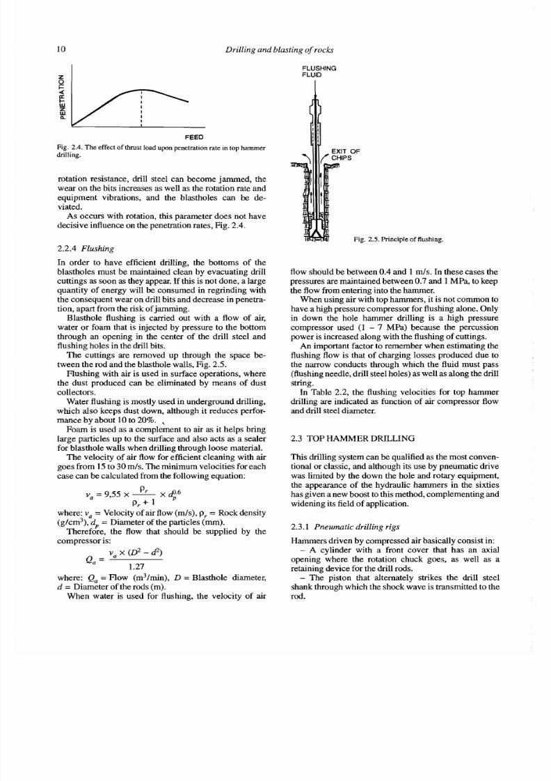
Fig. 2.4.The effec t of thmst load upon penetration rate in top hammerdnlling.
rotation resistance, drill steel can become jammed, thewear on the bits increases as well as the rotation rate andequipment vibrations, and the blastholes can be de-viated.
As occurs with rotation, this Parameter does not havedecisive influence on the penetration rates, Fig. 2.4.
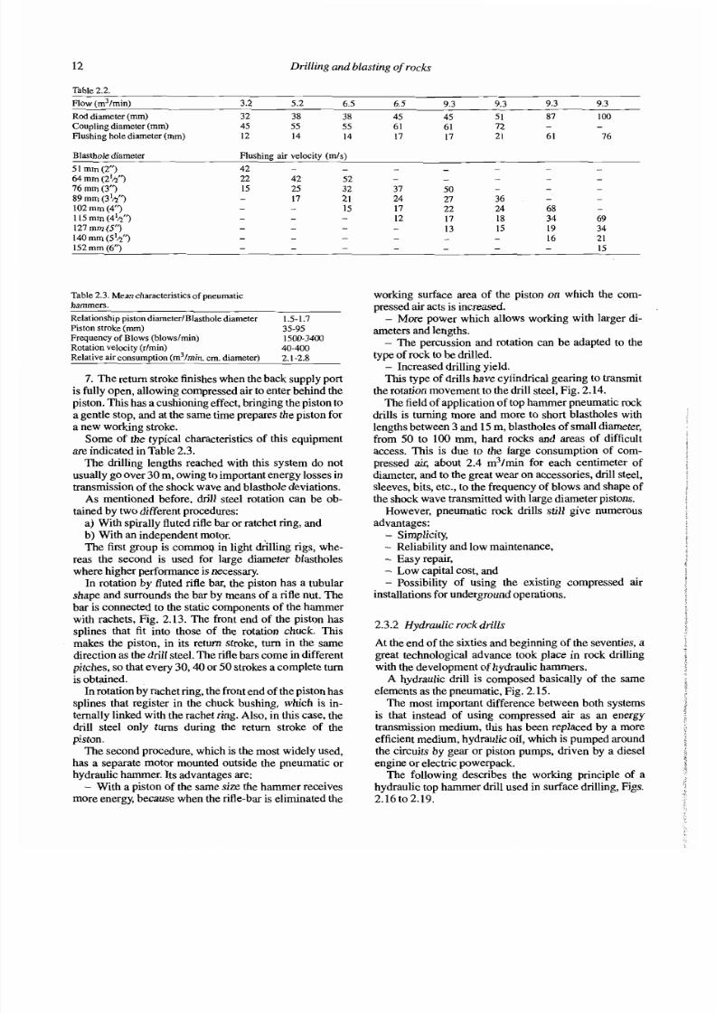
2.2.4 Flushing
FLUSHINGFLUID
In order to have efficient drilling, the bottoms of theblastholes must be maintained clean by evacuating drillcuttings as soon as they appear. If this is not done, a largequantity of energy will be consumed in regrinding withthe consequent wear on drill bits and decrease in penetra-tion, apart from the risk of jamming.
Blasthole flushing is carried out with a flow of air,water or foam that is injected by pressure to the bottomthrough an opening in the Center of the drill steel and
flushing holes in the dnll bits.The cuttings are removed up through the space be-
tween the rod and the blasthole walls, Fig. 2.5.Fiushing with air is used in surface operations, where
the dust produced can be eliminated by means of dustcollectors.
Water flushing is mostly used in underground drilling,which also keeps dust down, although it reduces perfor-mance by about 10 to 20%. ,
Foam is used as a complement to air as it helps bringlarge particles up to the surface and also acts as a seaierfor blasthole walls when drilling through loose material.
The velocity of air flow for efficient cleaning with airgoes from 15 to 30 mls. The minimum velocities for eachcase can be calculated from the following equation:
where: V , = Velocity of air flow (mls), pr = Rock density(g/cm3),d, = Diameter of the particles (mm).
Therefore, the flow that should be supplied by thecompressor is:
where: Qa = Fiow (m3/min), D = Blasthole diameter,d = Diameter of the rods (m).
When water is used for flushing, the velocity of air
Pnnciple of fiushing.
flow should be between 0.4 and 1 m/s. In these cases thepressures are maintained between 0.7 and 1MPa, to keepthe flow from entering into the hammer.
When using air with top hammers, it is not common tohave a high pressure compressor for flushing alone. Onlyin down the hole hammer drilling is a high pressurecompressor used (1 - 7 MPa) because the percussionpower is increased along with the flushing of cuttings.
An important factor to remember when estimating theflushing flow is that of charging losses produced due tothe narrow conducts through which the fluid must pass(flushing needle, drill steel holes) as well as along the dnllstnng.
In Table 2.2, the flushing velocities for top hammerdrilling are indicated as function of air compressor flowand drill steel diameter.
2.3 TOP HAMMER DRILLING
This drilling System can be qualified as the most conven-tional or classic, and although its use by pneumatic drivewas limited by the down the hole and rotary equipment,the appearance of the hydraulic hammers in the sixtieshas given a new boost to this method, complementing andwidening its field of application.
2.3.1 Pneumatic drilling rigs
Hammers driven by compressed air basicaily consist in:- A cylinder with a front Cover that has an axial
opening where the rotation chuck goes, as well as aretaining device for the drill rods.
- The piston that altemately strikes the dnll steelshank through which the shock wave is transmitted to therod.

7/28/2019 Drilling and Blasting in Rocks (sample)
http://slidepdf.com/reader/full/drilling-and-blasting-in-rocks-sample 21/81
Rotarypercussive drilling 11
- The valve that regulates the passage of compressedair in a pre-set volume and in alternating form to the front
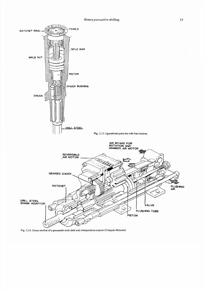
and back of the piston.- A rotation mechanism, that can be a spirally fluted
nfle bar or of independent rotation.
- A flushing System that consists in a tube that allowsthe passage of air to the inside of the drill steel.
Thes e elements are cornrnon to all the types of ham-mers o n the market, with only a few design c haractensticsthat differ: diameter of the cylinder, length of the pistonstroke, distribution valves, etc. The following describes
the working pnnciple of a pneumatic harnrner, Figs. 2.6to 2.12.
1. The piston is at the end of its return stroke and isready to Start its work ing stroke. T he air, at line pressure,fills the backhead (1) and passes through th e back supplyport (2) into the cylinder (3). The air pushes the piston
fonvard, beginning the working stroke. Meanwhile, thecylinder front end (5) is at atm ospheric pressure since the
exhaust port (6) is Open.2. T he piston (4) continues to accelerate forward, dri-
ven by the line pressure, until the leading ed ge (7) of thepistons control head shuts off the e ntrance of compressedair. The air confined in the back e nd of the cylinder (3)starts to expand and contiunes to d rive the piston forward.Note that the piston flange (4) closes the exhau st port (6)and that the front end is still at atmosph eric pressure.
3. The air confined at the back of the piston (3) con-
tinues to expand until the back edge of the piston flangestarts to uncover the exhaust port (6). Rem ember that the
piston control head (7) has already shut off the com-pressed air entrance, so that no compressed air will bewasted w hen the exhaust port is opened.
Up front, the piston has trapped air that was a atmophe-ric pressure (5), and has now compressed it to slightlyabove atmospheric pressure.
4. Th e piston continues to move forward because of its
momentum until it strikes the drill shank steel. Now, theback edge of the piston flange (8) has uncovered theexhaust port (6) and the air in the back en d is exhaustedinto the atmosphere. While this was going On, the backedge (10 ) of the control head o pened the front supply port
adrnitting compressedair
to the front end (5) driving thepiston back o n the return stroke. Dur ing this Stage there iscompressed air pushing against the piston from the front
end (5 ) and also pushing against the back end (10). Thefront surface area is much larger than the back (10) so thepiston moves towards the rear.
5. T he piston is accelerated back on the return stroke,until the back edg e of the control head (10) Covers up thefront air supply port. The air up fron t then continues topush the piston back.
6. T he piston continues to accelerate backwards whilethe air in the front end (5) expan ds until the front end ofthe piston flange (11) uncovers the exhaust port, trapping
the air in the back end of the cylinder and com pressing itto a pressure slightly more than atmospheric. Note thanthe front edg e of the con trol head (7 ) is just about to Openthe back supply port.
WFig . 2 .6 . Piston at the end of its return stroke.I
ig. 2 .7 . The piston accelerates forward.2.
W -Fig. 2. 8. The backe dge of the piston flange uncovers the exhaust port.
w -Fig . 2 .9 . The piston com presses the air in front of it.I
ig. 2.1 0. The piston is accelerated back.
7Fig. 2.1 1 . The front edge of the piston flange uncovers the exhaustport.
Fig. 2.1 2. Return strokeof the piston finishes.
7/28/2019 Drilling and Blasting in Rocks (sample)
http://slidepdf.com/reader/full/drilling-and-blasting-in-rocks-sample 22/81
7/28/2019 Drilling and Blasting in Rocks (sample)
http://slidepdf.com/reader/full/drilling-and-blasting-in-rocks-sample 23/81
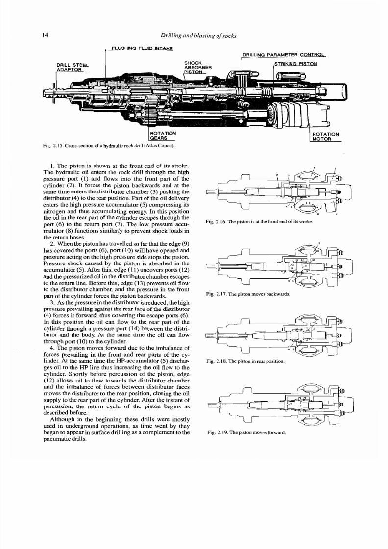
7/28/2019 Drilling and Blasting in Rocks (sample)
http://slidepdf.com/reader/full/drilling-and-blasting-in-rocks-sample 24/81
7/28/2019 Drilling and Blasting in Rocks (sample)
http://slidepdf.com/reader/full/drilling-and-blasting-in-rocks-sample 25/81
7/28/2019 Drilling and Blasting in Rocks (sample)
http://slidepdf.com/reader/full/drilling-and-blasting-in-rocks-sample 26/81

7/28/2019 Drilling and Blasting in Rocks (sample)
http://slidepdf.com/reader/full/drilling-and-blasting-in-rocks-sample 27/81
7/28/2019 Drilling and Blasting in Rocks (sample)
http://slidepdf.com/reader/full/drilling-and-blasting-in-rocks-sample 28/81
7/28/2019 Drilling and Blasting in Rocks (sample)
http://slidepdf.com/reader/full/drilling-and-blasting-in-rocks-sample 29/81
7/28/2019 Drilling and Blasting in Rocks (sample)
http://slidepdf.com/reader/full/drilling-and-blasting-in-rocks-sample 30/81
7/28/2019 Drilling and Blasting in Rocks (sample)
http://slidepdf.com/reader/full/drilling-and-blasting-in-rocks-sample 31/81
7/28/2019 Drilling and Blasting in Rocks (sample)
http://slidepdf.com/reader/full/drilling-and-blasting-in-rocks-sample 32/81
7/28/2019 Drilling and Blasting in Rocks (sample)
http://slidepdf.com/reader/full/drilling-and-blasting-in-rocks-sample 33/81
7/28/2019 Drilling and Blasting in Rocks (sample)
http://slidepdf.com/reader/full/drilling-and-blasting-in-rocks-sample 34/81
7/28/2019 Drilling and Blasting in Rocks (sample)
http://slidepdf.com/reader/full/drilling-and-blasting-in-rocks-sample 35/81
7/28/2019 Drilling and Blasting in Rocks (sample)
http://slidepdf.com/reader/full/drilling-and-blasting-in-rocks-sample 36/81
7/28/2019 Drilling and Blasting in Rocks (sample)
http://slidepdf.com/reader/full/drilling-and-blasting-in-rocks-sample 37/81
7/28/2019 Drilling and Blasting in Rocks (sample)
http://slidepdf.com/reader/full/drilling-and-blasting-in-rocks-sample 38/81

7/28/2019 Drilling and Blasting in Rocks (sample)
http://slidepdf.com/reader/full/drilling-and-blasting-in-rocks-sample 39/81
7/28/2019 Drilling and Blasting in Rocks (sample)
http://slidepdf.com/reader/full/drilling-and-blasting-in-rocks-sample 40/81

7/28/2019 Drilling and Blasting in Rocks (sample)
http://slidepdf.com/reader/full/drilling-and-blasting-in-rocks-sample 41/81
7/28/2019 Drilling and Blasting in Rocks (sample)
http://slidepdf.com/reader/full/drilling-and-blasting-in-rocks-sample 42/81
7/28/2019 Drilling and Blasting in Rocks (sample)
http://slidepdf.com/reader/full/drilling-and-blasting-in-rocks-sample 43/81

7/28/2019 Drilling and Blasting in Rocks (sample)
http://slidepdf.com/reader/full/drilling-and-blasting-in-rocks-sample 44/81
7/28/2019 Drilling and Blasting in Rocks (sample)
http://slidepdf.com/reader/full/drilling-and-blasting-in-rocks-sample 45/81
7/28/2019 Drilling and Blasting in Rocks (sample)
http://slidepdf.com/reader/full/drilling-and-blasting-in-rocks-sample 46/81
7/28/2019 Drilling and Blasting in Rocks (sample)
http://slidepdf.com/reader/full/drilling-and-blasting-in-rocks-sample 47/81
7/28/2019 Drilling and Blasting in Rocks (sample)
http://slidepdf.com/reader/full/drilling-and-blasting-in-rocks-sample 48/81
7/28/2019 Drilling and Blasting in Rocks (sample)
http://slidepdf.com/reader/full/drilling-and-blasting-in-rocks-sample 49/81
7/28/2019 Drilling and Blasting in Rocks (sample)
http://slidepdf.com/reader/full/drilling-and-blasting-in-rocks-sample 50/81
7/28/2019 Drilling and Blasting in Rocks (sample)
http://slidepdf.com/reader/full/drilling-and-blasting-in-rocks-sample 51/81
7/28/2019 Drilling and Blasting in Rocks (sample)
http://slidepdf.com/reader/full/drilling-and-blasting-in-rocks-sample 52/81

7/28/2019 Drilling and Blasting in Rocks (sample)
http://slidepdf.com/reader/full/drilling-and-blasting-in-rocks-sample 53/81
7/28/2019 Drilling and Blasting in Rocks (sample)
http://slidepdf.com/reader/full/drilling-and-blasting-in-rocks-sample 54/81
7/28/2019 Drilling and Blasting in Rocks (sample)
http://slidepdf.com/reader/full/drilling-and-blasting-in-rocks-sample 55/81
7/28/2019 Drilling and Blasting in Rocks (sample)
http://slidepdf.com/reader/full/drilling-and-blasting-in-rocks-sample 56/81
7/28/2019 Drilling and Blasting in Rocks (sample)
http://slidepdf.com/reader/full/drilling-and-blasting-in-rocks-sample 57/81
7/28/2019 Drilling and Blasting in Rocks (sample)
http://slidepdf.com/reader/full/drilling-and-blasting-in-rocks-sample 58/81
7/28/2019 Drilling and Blasting in Rocks (sample)
http://slidepdf.com/reader/full/drilling-and-blasting-in-rocks-sample 59/81

7/28/2019 Drilling and Blasting in Rocks (sample)
http://slidepdf.com/reader/full/drilling-and-blasting-in-rocks-sample 60/81
7/28/2019 Drilling and Blasting in Rocks (sample)
http://slidepdf.com/reader/full/drilling-and-blasting-in-rocks-sample 61/81

7/28/2019 Drilling and Blasting in Rocks (sample)
http://slidepdf.com/reader/full/drilling-and-blasting-in-rocks-sample 62/81
7/28/2019 Drilling and Blasting in Rocks (sample)
http://slidepdf.com/reader/full/drilling-and-blasting-in-rocks-sample 63/81
7/28/2019 Drilling and Blasting in Rocks (sample)
http://slidepdf.com/reader/full/drilling-and-blasting-in-rocks-sample 64/81
7/28/2019 Drilling and Blasting in Rocks (sample)
http://slidepdf.com/reader/full/drilling-and-blasting-in-rocks-sample 65/81
7/28/2019 Drilling and Blasting in Rocks (sample)
http://slidepdf.com/reader/full/drilling-and-blasting-in-rocks-sample 66/81
7/28/2019 Drilling and Blasting in Rocks (sample)
http://slidepdf.com/reader/full/drilling-and-blasting-in-rocks-sample 67/81

7/28/2019 Drilling and Blasting in Rocks (sample)
http://slidepdf.com/reader/full/drilling-and-blasting-in-rocks-sample 68/81
7/28/2019 Drilling and Blasting in Rocks (sample)
http://slidepdf.com/reader/full/drilling-and-blasting-in-rocks-sample 69/81
7/28/2019 Drilling and Blasting in Rocks (sample)
http://slidepdf.com/reader/full/drilling-and-blasting-in-rocks-sample 70/81
7/28/2019 Drilling and Blasting in Rocks (sample)
http://slidepdf.com/reader/full/drilling-and-blasting-in-rocks-sample 71/81
7/28/2019 Drilling and Blasting in Rocks (sample)
http://slidepdf.com/reader/full/drilling-and-blasting-in-rocks-sample 72/81
7/28/2019 Drilling and Blasting in Rocks (sample)
http://slidepdf.com/reader/full/drilling-and-blasting-in-rocks-sample 73/81
7/28/2019 Drilling and Blasting in Rocks (sample)
http://slidepdf.com/reader/full/drilling-and-blasting-in-rocks-sample 74/81
7/28/2019 Drilling and Blasting in Rocks (sample)
http://slidepdf.com/reader/full/drilling-and-blasting-in-rocks-sample 75/81
7/28/2019 Drilling and Blasting in Rocks (sample)
http://slidepdf.com/reader/full/drilling-and-blasting-in-rocks-sample 76/81

7/28/2019 Drilling and Blasting in Rocks (sample)
http://slidepdf.com/reader/full/drilling-and-blasting-in-rocks-sample 77/81
7/28/2019 Drilling and Blasting in Rocks (sample)
http://slidepdf.com/reader/full/drilling-and-blasting-in-rocks-sample 78/81
7/28/2019 Drilling and Blasting in Rocks (sample)
http://slidepdf.com/reader/full/drilling-and-blasting-in-rocks-sample 79/81
7/28/2019 Drilling and Blasting in Rocks (sample)
http://slidepdf.com/reader/full/drilling-and-blasting-in-rocks-sample 80/81
7/28/2019 Drilling and Blasting in Rocks (sample)
http://slidepdf.com/reader/full/drilling-and-blasting-in-rocks-sample 81/81