drn80 – 315
TRANSCRIPT

5Drive selectionNotes on electromagnetic compatibility – EMC
Catalog – DRN80 – 315 95
5 Drive selectionObserve the explanations and notes in this chapter during drive selection.
5.1 Notes on electromagnetic compatibility – EMC5.1.1 EMC Directive 2014/30/EU
AC motors are designed for use as components for installation in machinery and sys-tems. The manufacturer of the machine or system is responsible for complying withthe EMC Directive 2014/30/EU.
5.1.2 EMC measuresThe motor can be equipped with grounding terminals, depending on size and design.• External grounding terminals LF (low frequency grounding)• External grounding terminals HF (high frequency grounding)Metallic cable glands and shielded cables increase the electromagnetic compatibility.
5.1.3 Line operationAC (brake) motors by SEW‑EURODRIVE adhere to the EMC requirements ofEN 60034‑1 when used in accordance with their designated use in continuous duty.No interference prevention measures are required.
5.1.4 Switching operationSwitching operation of the motor requires suitable measures for interference suppres-sion from the switching device.
2213
4204
/EN
– 1
2/20
17
5

5 Drive selectionNotes on electromagnetic compatibility – EMC
Catalog – DRN80 – 31596
5.1.5 Safe switching of motor and brakesNote the information in the following sections for switching of inductances.
Switching of motor windingsSwitching of motor windings can create voltage peaks. Voltage peaks can damagewindings and contacts. To avoid this, install the incoming cables with varistors.
Switching of brake coilsVaristors must be used in order to avoid harmful overvoltages caused by switching op-erations in the DC circuit of disk brakes.All brake control systems from SEW‑EURODRIVE are equipped with varistors asstandard.Observe the dimensioning specifications for switch contacts, voltage supply cables,and fusing in chapter "Dimensioning the periphery" (→ 2 267).
Suppressor circuit on the switching devicesAccording to standard EN 60204 (Electrical Equipment of Machines), motor windingsmust be equipped with interference suppression to protect the numerical or program-mable logic controllers. Because problems are primarily caused by switching opera-tions, we recommend installing suppressor circuits on the switching devices.
2213
4204
/EN
– 1
2/20
17
5Drive selectionDrive selection – non-controlled motor
Catalog – DRN80 – 315 97
5.2 Drive selection – non-controlled motor5.2.1 Flow diagram
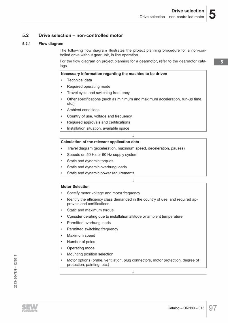
The following flow diagram illustrates the project planning procedure for a non-con-trolled drive without gear unit, in line operation.For the flow diagram on project planning for a gearmotor, refer to the gearmotor cata-logs.
Necessary information regarding the machine to be driven• Technical data• Required operating mode• Travel cycle and switching frequency• Other specifications (such as minimum and maximum acceleration, run-up time,
etc.)• Ambient conditions• Country of use, voltage and frequency• Required approvals and certifications• Installation situation, available space
↓
Calculation of the relevant application data• Travel diagram (acceleration, maximum speed, deceleration, pauses)• Speeds on 50 Hz or 60 Hz supply system• Static and dynamic torques• Static and dynamic overhung loads• Static and dynamic power requirements
↓
Motor Selection• Specify motor voltage and motor frequency• Identify the efficiency class demanded in the country of use, and required ap-
provals and certifications• Static and maximum torque• Consider derating due to installation altitude or ambient temperature• Permitted overhung loads• Permitted switching frequency• Maximum speed• Number of poles• Operating mode• Mounting position selection• Motor options (brake, ventilation, plug connectors, motor protection, degree of
protection, painting, etc.)
↓
2213
4204
/EN
– 1
2/20
17
5

5 Drive selectionDrive selection – non-controlled motor
Catalog – DRN80 – 31598
Optional: Brake selection• Determine brake size and braking torque• Brake control• Braking work• Number of braking operations per hour• Braking distance• Braking time
↓
Make sure that all requirements have been met.
Also refer to chapter "Nominal data of a 50 Hz motor when operated on a 60 Hz sup-ply system" (→ 2 116).
2213
4204
/EN
– 1
2/20
17

5Drive selectionDrive selection – controlled motor
Catalog – DRN80 – 315 99
5.3 Drive selection – controlled motor
5.3.1 Inverter operation
Suitability for operating with an inverterAC motors by SEW‑EURODRIVE can be operated with inverters.
Installation noteFor operating AC motors with an inverter, refer to the installation and EMC instructionsprovided by the inverter manufacturer.
Brakemotor operation with inverterInstall the brake cables of brakemotors separately from the other power cables, main-taining a distance of at least 200 mm. Joint installation is only permitted if either thebrake cable or the power cable is shielded.
Connection of a speed sensor to the inverterObserve the following instructions when connecting the speed sensor:• Only use a shielded cable with twisted pair conductors.• Connect the shield to the PE potential on both ends over a large surface area.• Route signal cables separately from power cables or brake cables (minimum dis-
tance 200 mm).
Connection of a PTC thermistor /TF to the inverterInstall the connecting lead of the positive temperature coefficient (PTC) thermistor /TFseparately from power cables, maintaining a distance of at least 200 mm between thelines. Laying together is only permitted if either the cable of the PTC thermistor /TF orthe power cable is shielded.
2213
4204
/EN
– 1
2/20
17
5

5 Drive selectionDrive selection – controlled motor
Catalog – DRN80 – 315100
5.3.2 Flow diagramThe following flow diagram illustrates the determination procedure for a controlleddrive. The drive consists of a motor that is powered by an inverter.For the flow diagram on project planning for a gearmotor, refer to the gearmotor cata-logs.
Necessary information regarding the machine to be driven• Technical data• Travel cycle• Speed setting range• Positioning accuracy• Ambient conditions• Country of use, voltage and frequency• Required approvals and certifications• Installation conditions
↓
Calculation of the relevant application data• Travel diagram (acceleration, maximum speed, deceleration, pauses)• Speeds• Static and dynamic torques• Static and dynamic overhung loads• Static and dynamic power requirements• Regenerative power and cyclic duration factor• Thermal rms torque• Thermal rms power
↓
Motor Selection• Specify motor voltage and motor frequency• Identify the efficiency class demanded in the country of use, required approvals
and certifications• Static and maximum torque• Consider derating due to installation altitude or ambient temperature• Observe dynamic and thermal torque curves• Permitted overhung loads• Maximum speed• Number of poles• Operating mode• Mounting position selection• Encoder selection based on requirements• Motor options (brake, ventilation, plug connectors, thermal motor protection, de-
gree of protection, painting, etc.)
↓
2213
4204
/EN
– 1
2/20
17

5Drive selectionDrive selection – controlled motor
Catalog – DRN80 – 315 101
Optional: Brake selection• Determine brake size and braking torque• Brake control• Braking work• Number of braking operations per hour• Braking distance• Braking time
↓
Selecting the inverter• Motor/inverter assignment• Continuous current and peak current for current-controlled inverters/axes• Selection of addition inverter options according to functional requirements
↓
Selecting the braking resistor• Based on the calculated regenerative power• Based on the cyclic duration factor and peak braking power
↓
Inverter options• EMC measures• Operation/communication• Additional functions• Functional safety technology, if required
↓
Make sure that all requirements have been met.
2213
4204
/EN
– 1
2/20
17
5
5 Drive selectionDrive selection – controlled motor
Catalog – DRN80 – 315102
5.3.3 Product range of inverters by SEW‑EURODRIVEThe extensive product range of SEW-EURODRIVE inverters is available for designingelectronically controlled drives.Inverters are distinguished in decentralized installations (mounting close to the motorin high degree of protection) and installations in the control cabinet or near the controlcabinet. The following section lists the inverters for installation in the control cabinet orinstallation near the control cabinet.
Decentralized in-stallation
• MOVI4RU®
The decentralized inverter MOVI4R-U® in degree of protection IP54 and powerrange 0.25 – 4.0 kW is designed for open-loop speed control of asynchronous mo-tors without encoder. Installation and startup procedure are optimized for simpleapplications.
• MOVIFIT® compactThe decentralized inverter MOVIFIT® compact in degree of protection IP55 andpower range 0.37 – 1.5 kW is designed for open-loop speed control of asynchro-nous motors without encoder. The inverter does not require space in the centralcontrol cabinet due to the installation close to the motor. Installation and startupprocedure are optimized for simple intralogistics applications.
• MOVIFIT® FCThe decentralized inverter MOVIFIT® FC in degree of protection IP65 and powerrange 0.25 – 4 kW is designed for speed control of asynchronous motors withoutencoder. The inverter does not require space in the central control cabinet due tothe installation close to the motor. The robust housing technology of MOVIFIT® isavailable in various hygienic surface designs that reliably protect the inverter evenin demanding environments, such as in the beverage industry where the devicesare subject to humidity and cleaning agents.
• MOVIPRO®
The decentralized application controller MOVIPRO® in degree of protection IP54and power range 2.2 – 15 kW is designed for torque control, speed control, andpositioning control of asynchronous motors and synchronous motors. MOVIPRO®
is not only an inverter but also includes the following functions: Controller, inverter,energy management, brake management, communication, functional safety, andconnection technology. With these functions, MOVIPRO® combines all functions ofdecentralized system installations without control cabinet, and thus ensures thatsystems are flexible, modular, and standardized.
Installation in thecontrol cabinet
• MOVITRAC® LTE-BThe simple inverter MOVITRAC® LTE-B in degree of protection IP20 and powerrange 0.37 – 11 kW, and in degree of protection IP66 and power range 0.37 – 7.5 kW is designed for open-loop speed control of asynchronous motors withoutencoder. The inverter is defined by a compact design and especially easy handlingin conveyor systems, pumps, and fans. The design variant in high degree of pro-tection can be mounted outside of the control cabinet and includes the requiredequipment such as EMC measures.
• MOVITRAC® LTP-BThe standard inverter MOVITRAC® LTP-B in degree of protection IP20 and powerrange 0.37 – 11 kW, IP66 and power range 0.37 – 7.5 kW, and IP55 and powerrange 11 – 160 kW is designed for speed control of asynchronous motors and syn-chronous motors without encoder. The design variants in high degree of protectioncan be mounted outside of the control cabinet and includes the required equip-ment such as EMC measures or the safety function STO. MOVITRAC® LTP-B isdefined by comfortable startup in conveyor systems, hoists, pumps, and fans.
2213
4204
/EN
– 1
2/20
17

5Drive selectionDrive selection – controlled motor
Catalog – DRN80 – 315 103
• MOVITRAC® BThe standard inverter MOVITRAC® B in degree of protection IP10/IP20 and powerrange 0.25 – 75 kW is designed for speed control of asynchronous motors withoutencoder. The universal inverter is suitable for versatile applications in conveyingand materials handling technology as it combines the vector control mode VFC,the integrated safety function STO, extensive accessories, and a modular struc-ture.
• MOVIDRIVE® BThe application inverter MOVIDRIVE® B in degree of protection IP10/IP20 andpower range 0.55 – 315 kW is designed for torque control, speed control, and pos-itioning control of asynchronous motors and synchronous motors. The large num-ber of basic functionalities, the broad spectrum of options, and the excessive ac-cessories make MOVIDRIVE® B a universal application inverter for all types of ap-plication. In combination with control technology by SEW‑EURODRIVE,MOVIDRIVE® B is the ideal device, both technically and economically, for demand-ing tasks in conveying, handling technology, processing technology, and kinemat-ics.
• MOVIDRIVE® systemThe application inverter MOVIDRIVE® system in degree of protection IP20 andcurrent range 2 – 588 A is designed for torque control, speed control, and position-ing control of asynchronous motors and synchronous motors. In combination withMOVI-C® CONTROLLER, MOVIDRIVE® system performs tasks with high require-ments in regard of dynamics, functional safety, and kinematics. MOVIDRIVE® sys-tem is the optimal inverter, when the focus lies on high functionality, large powerranges, long motor cables, and high availability.
• MOVIDRIVE® modularThe application inverter MOVIDRIVE® modular in degree of protection IP20 con-sists of a power supply module with 10 – 110 kW and connected axis modules with2 – 180 A. The focus of this modular design lies on compact design and energyexchange between drives via a DC link connection. MOVDIRVE® modular meetsthe most demanding requirements in regard of dynamics, energy management,functional safety, and kinematics. In combination with the MOVI-C®
CONTROLLER, all applications ranging from materials handling technology to ma-chine automation with predefined, parameterizable function units, to free program-ming in IEC 61131, can be implemented quickly and flexible, while highly cost-effi-cient.
2213
4204
/EN
– 1
2/20
17
5

5 Drive selectionDrive selection – controlled motor
Catalog – DRN80 – 315104
Product characteristics of invertersThe following table lists the most important product characteristics for the various in-verter series. You can choose the inverter series matching your application based onthese product characteristics.
Decentralized installation
MOVI4RU®, MOVIFIT® compact, MOVIFIT® FC, MOVIPRO®,Product features MOVI4RU® MOVIFIT® compact MOVIFIT® FC MOVIPRO®
Voltage range 1 × AC 200 – 240 V(0.25 – 0.55 kW)
3 × AC 380 – 500 V 3 × AC 380 – 500 V 3 × AC 380 – 500 V
3 × AC 200 – 240 V(0.25 – 0.55 kW)
– – –
3 × AC 380 – 480 V(0.25 – 1.1 kW)
– – –
Power range 0.25 – 1,1 kW 0.25 – 4 kW 0.25 – 4 kW 2.2 – 22 kW
Overload capacity150% IN for 60 seconds
100% IN continuously in operation without overload4Q capable No No Yes, with integrated brake chopper as standard
Control mode
V/f V/f V/f V/fLVFC voltage-controlled
vector controlVFC voltage-controlled vector control
– – – CFC/Servo current-con-trolled vector control
Encoder input No No No OptionTorque control No No No YesSpeed control Yes Yes Yes YesPosition control No No No YesSerial interfaces No No System bus (SBus) and
RS485–
Fieldbus interfaces No AS-InterfaceSBus1)
PROFIBUS, PROFINET IO, PROFINET POF,DeviceNet™, Ethernet/IP™, Modbus TCP
Maximum output frequency 599 Hz 599 Hz 599 Hz 599 HzSTO – Safe Torque Off No No Yes YesApprovals and certifications CE, UL, cUL, RCM, EAC CE, UL1), cUL1), RCM,
EACCE, UL, cUL, RCM, EAC
1) in preparation for MOVIFIT® compact
2213
4204
/EN
– 1
2/20
17

5Drive selectionDrive selection – controlled motor
Catalog – DRN80 – 315 105
Control cabinet installation
MOVITRAC® LTE-B, MOVITRAC® LTP-B, MOVITRAC® BProduct features MOVITRAC® LTE-B MOVITRAC® LTP-B MOVITRAC® BVoltage range 1 × AC 110 – 120 V
(0.37 – 1.1 kW)1 × AC 200 – 240 V
(0.75 – 2.2 kW)1 × AC 200 – 240 V
(0.25 – 2.2 kW)1 × AC 200 – 240 V
(0.75 – 4.0 kW)3 × AC 200 – 240 V
(0.75 – 75 kW)3 × AC 200 – 240 V
(0.25 – 30 kW)3 × AC 200 – 240 V
(0.37 – 4.0 kW)3 × AC 380 – 480 V
(0.75 – 160 kW)3 × AC 380 – 500 V
(0.25 – 75 kW)3 × AC 380 – 480 V
(0.75 – 11 kW)3 × AC 500 – 600 V
(0.75 – 110 kW)–
Power range 0.37 – 11 kW (IP20) 0.75 – 15 kW (IP20)0.25 – 75 kW
0.37 – 7.5 kW (IP66) 0.75 – 160 kW (IP55)Overload capacity 150% IN for 60 seconds 150% IN for 60 seconds 150% IN for 60 seconds
175% IN for 2 seconds 175% IN for 2 seconds 125% IN continuously in opera-tion without overload
4Q capable Size 1 without brake chopper,size 2 and size 3 as standard Yes, with integrated brake chopper as standard
Control mode V/f V/f V/fVFC voltage-controlled vector
controlVFC voltage-controlled vector
controlVFC voltage-controlled vector
controlEncoder input No No NoTorque control No Yes NoSpeed control Yes Yes YesPosition control No No NoSerial interfaces System bus (SBus) and RS485Fieldbus interfaces Optionally via gateway
PROFIBUS, EtherCAT®,PROFINET, DeviceNet™, Ether-
net/IP™
Optionally via gatewayPROFIBUS, EtherCAT®,
PROFINET, DeviceNet™, Ether-net/IP™
Optionally via gatewayPROFIBUS, CANopen,
DeviceNet™, PROFINET IO,EtherNet/IP™, EtherCAT®
Maximum output frequency 500 Hz 500 Hz 599 HzSTO – Safe Torque Off No Yes Yes (3-phase devices)Approvals and certifications CE, UL, cUL, RCM, EAC
2213
4204
/EN
– 1
2/20
17
5

5 Drive selectionDrive selection – controlled motor
Catalog – DRN80 – 315106
MOVIDRIVE® B, MOVIDRIVE® system, MOVIDRIVE® modularProduct features MOVIDRIVE® B MOVIDRIVE® system MOVIDRIVE® modularVoltage range 3 × AC 200 – 240 V
(1.5 – 30 kW)3 × AC 200 – 240 V
(7 –108 A)3 × AC 380 – 500 V
3 × AC 380 – 500 V (0.55 – 315 kW)
3 × AC 380 – 500 V (2 – 588 A)
–
Performance/current range0.55 – 250 kW –
10 – 110 kW (power supply mod-ules)
2 – 180 A (axis modules)Overload capacity 150% IN for 60 seconds 200% IN for 3 seconds 250% IN for 1 second
125% IN continuously in opera-tion without overload
125% IN continuously in opera-tion without overload
150% IN for 30 seconds
4Q capable Yes, with integrated brake chopper as standardControl mode V/f V/f V/f
VFC voltage-controlled vectorcontrol
VFCPLUS voltage-controlled vectorcontrol
VFCPLUS voltage-controlled vectorcontrol
CFC/Servo current-controlledvector control
CFC/Servo current-controlledvector control
CFC/Servo current-controlledvector control
– ELSM® for synchronous motorswithout encoders
ELSM® for synchronous motorswithout encoders
Encoder input Option Yes YesTorque control Yes Yes YesSpeed control Yes Yes YesPosition control Yes Yes YesSerial interfaces System bus (SBus) and RS485 EtherCAT/SbusPLUS
Fieldbus interfaces Optionally PROFIBUS DP,CANopen, DeviceNet™,
PROFINET IO, EtherNet/IP™,EtherCAT®
PROFIBUS, PROFINET, PROFISAFE, EtherNet/IP™, ModbusTCP/IP
Maximum output frequency 599 Hz 599 Hz 599 HzSTO – Safe Torque Off Yes Yes YesApprovals and certifications CE, UL, cUL, RCM, EAC
2213
4204
/EN
– 1
2/20
17

5Drive selectionDrive selection – controlled motor
Catalog – DRN80 – 315 107
5.3.4 Non-SEW inverterDRN.. motors can be operated at third-party inverts. Observe the information on useat third-party inverters, see chapter "DRN.. AC motors on third-party invert-ers" (→ 2 108).
5.3.5 Reinforced insulation for inverter operationWhen asynchronous motors are operated at an inverter, the winding is subject tohigher loads than would be the case in line operation without inverter.An inverter pulses the DC voltage of the DC link (Uz) to the supply cables to the motor.This pulsing takes place in the kHz range, which means several thousand ON andOFF switchings per second – at SEW-EURODRIVE usually with 4, 8, or 16 kHz.The standard winding can resist voltage peaks up to:• Line-to-line voltages ULL = 1560 V• Line-to-ground voltages ULG = 1100 VAs a result, using SEW‑EURODRIVE AC motors with standard winding at an inverteris permitted up to 500 V.If a motor is operated at an inverter under the following conditions, the double voltagepulse can exceed the maximum permissible value of the standard winding of 1560 V:• The inverter supplies the motor with a voltage of 600 V or higher.• The DC link voltage is increased to DC 742.5 V.Additional measures are required to protect the motor winding. The options reinforcedwinding insulation /RI (chapter "Reinforced winding insulation" (→ 2 408)) and rein-forced winding insulation with increased resistance against partial discharge /RI2, seechapter "Reinforced winding insulation with increased resistance against partial dis-charge" (→ 2 408) are available.
2213
4204
/EN
– 1
2/20
17
5

5 Drive selectionDrive selection – controlled motor
Catalog – DRN80 – 315108
5.3.6 DRN.. AC motors on third-party invertersWhen motors are powered from inverters, you must observe the wiring instructions is-sued by the inverter manufacturer. It is essential that you observe the operating in-structions for the inverter.Operating SEW motors on third-party inverters is permitted if the pulse voltages at themotor terminals indicated in the following figure are not exceeded.
0.6
0.8
1.0
1.2
1.4
1.6
1.8
2.0
0 0.2 0.4 0.6 0.8 1 1.2 1.4
[1]
[2]
[3]
2.2
[4]
[5]
[µs]
UL
L [
kV
]
[6]
[7]
20985509387
[1] Permitted pulse voltage for motors with reinforced insulation and increased res-istance against partial discharge (/RI2)
[2] Permitted pulse voltage for motors with reinforced insulation (/RI)
[3] Permitted pulse voltage according to NEMA MG1 part 31, VN ≤ 500 V
[4] Permitted pulse voltage for nominal voltages VN ≤ 500 V, star connection
[5] Permitted pulse voltage for nominal voltages VN ≤ 500 V, delta connection
[6] Duration of voltage increase
[7] Permitted pulse voltage
INFORMATIONCompliance with the limit values must be checked and taken into account as follows:• The supply voltage level at the third-party inverter• The threshold of the brake chopper voltage• The operating mode of the motor (motoring/regenerative)
→ If the permitted pulse voltage is exceeded, you must install limiting measures,such as filters, chokes or special motor cables. Consult the manufacturer of the in-verter.
2213
4204
/EN
– 1
2/20
17
5Drive selectionDrive selection – controlled motor
Catalog – DRN80 – 315 109
5.3.7 IVIC Class for MotorsThe standard IEC 60034-18-41:2014 defines the stress categories for motors with thefollowing characteristics:• Nominal voltages over 300 V• With electrical insulation system that is free of partial discharge• Operation at a frequency inverter with intermediate voltage circuitThe stress categories, or impulse voltage insulation classes (IVIC), are divided intoclasses A to D.
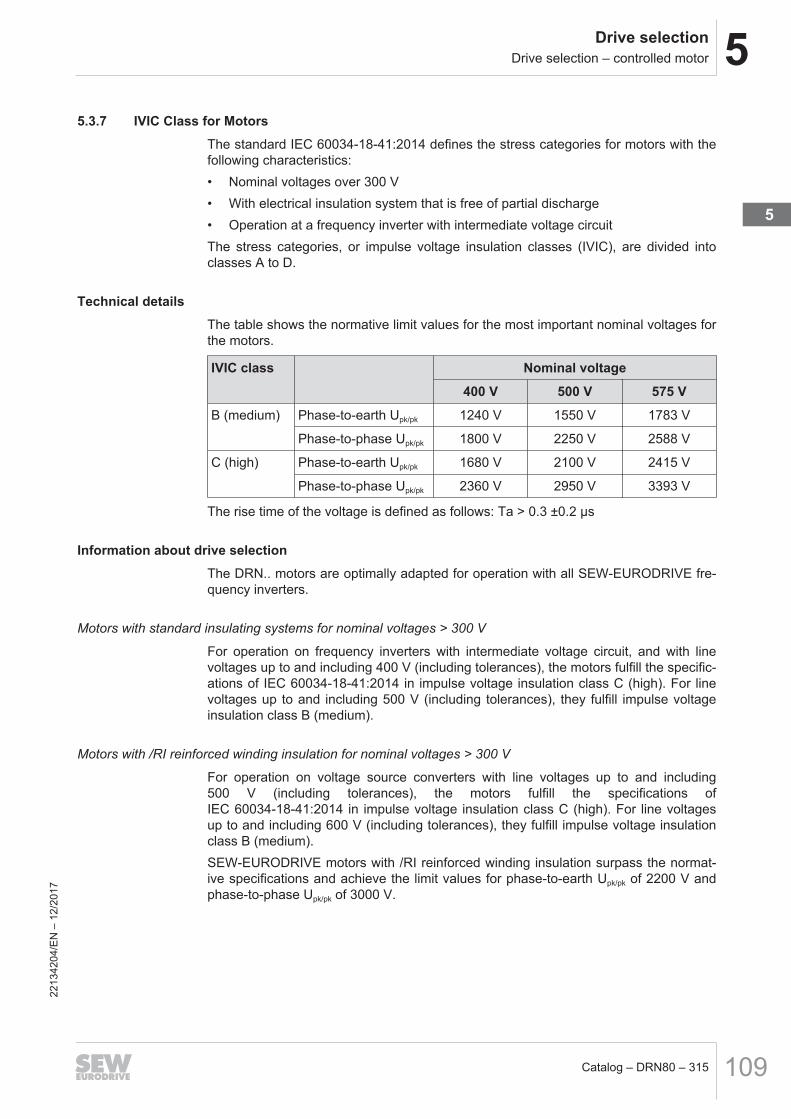
Technical detailsThe table shows the normative limit values for the most important nominal voltages forthe motors.
IVIC class Nominal voltage400 V 500 V 575 V
B (medium) Phase-to-earth Upk/pk 1240 V 1550 V 1783 V
Phase-to-phase Upk/pk 1800 V 2250 V 2588 V
C (high) Phase-to-earth Upk/pk 1680 V 2100 V 2415 V
Phase-to-phase Upk/pk 2360 V 2950 V 3393 V
The rise time of the voltage is defined as follows: Ta > 0.3 ±0.2 μs
Information about drive selectionThe DRN.. motors are optimally adapted for operation with all SEW‑EURODRIVE fre-quency inverters.
Motors with standard insulating systems for nominal voltages > 300 V
For operation on frequency inverters with intermediate voltage circuit, and with linevoltages up to and including 400 V (including tolerances), the motors fulfill the specific-ations of IEC 60034-18-41:2014 in impulse voltage insulation class C (high). For linevoltages up to and including 500 V (including tolerances), they fulfill impulse voltageinsulation class B (medium).
Motors with /RI reinforced winding insulation for nominal voltages > 300 V
For operation on voltage source converters with line voltages up to and including500 V (including tolerances), the motors fulfill the specifications ofIEC 60034-18-41:2014 in impulse voltage insulation class C (high). For line voltagesup to and including 600 V (including tolerances), they fulfill impulse voltage insulationclass B (medium).SEW‑EURODRIVE motors with /RI reinforced winding insulation surpass the normat-ive specifications and achieve the limit values for phase-to-earth Upk/pk of 2200 V andphase-to-phase Upk/pk of 3000 V.
2213
4204
/EN
– 1
2/20
17
5

5 Drive selectionDrive selection – controlled motor
Catalog – DRN80 – 315110
Order informationUpon request, the permissible IVIC class can be displayed on the motor in the form ofan additional label.The permissible IVIC class is also then specified for SEW‑EURODRIVE motors in theorder confirmation.The following illustration depicts an example for a motor label with standard insulationsystem:
IVIC CIEC 60034 -18- 41:2014
Uline ≤ 400V
13
99
99
9 9
20562235915
The following illustration depicts an example for a motor label with the option rein-forced winding insulation /RI, depending on the nominal voltage:
IVIC C
13
99
99
9 9
IEC 60034 -18- 41:2014
Uline ≤ 500V
20562391947
IVIC B
13
99
99
9 9
IEC 60034 -18- 41:2014
Uline ≤ 600V
20562233483
2213
4204
/EN
– 1
2/20
17
5Drive selectionDrive selection – controlled motor
Catalog – DRN80 – 315 111
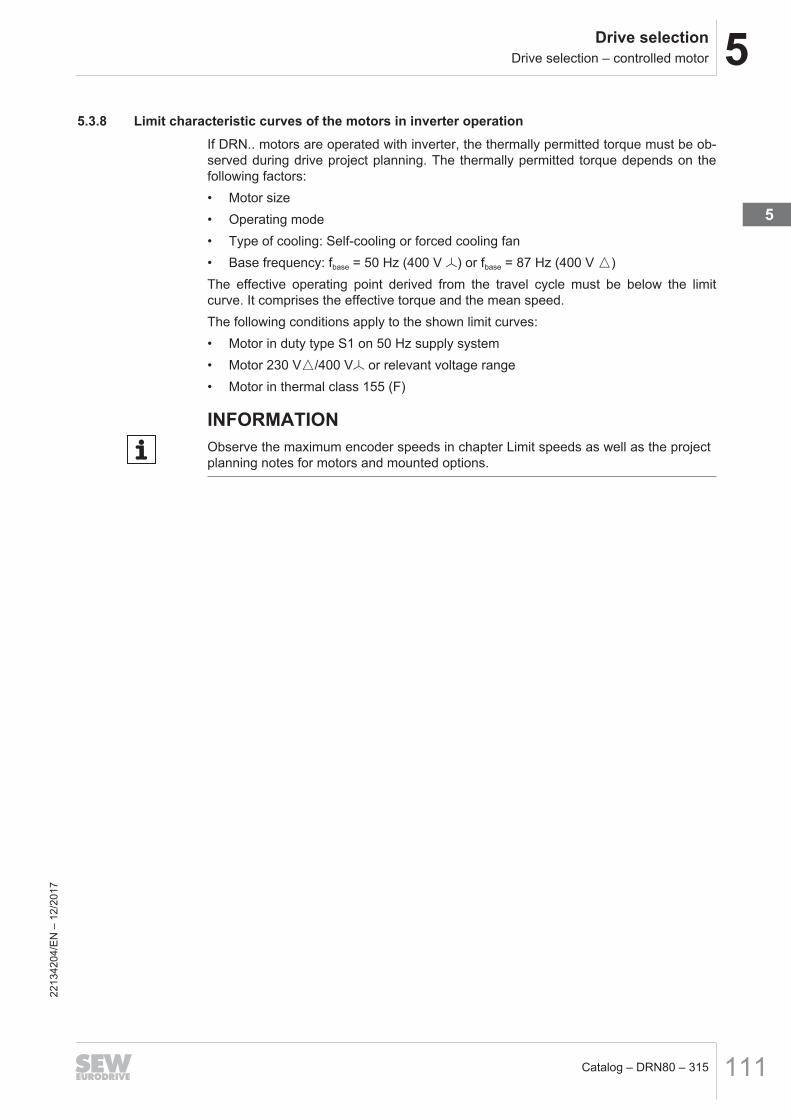
5.3.8 Limit characteristic curves of the motors in inverter operationIf DRN.. motors are operated with inverter, the thermally permitted torque must be ob-served during drive project planning. The thermally permitted torque depends on thefollowing factors:• Motor size• Operating mode• Type of cooling: Self-cooling or forced cooling fan• Base frequency: fbase = 50 Hz (400 V W) or fbase = 87 Hz (400 V m)The effective operating point derived from the travel cycle must be below the limitcurve. It comprises the effective torque and the mean speed.The following conditions apply to the shown limit curves:• Motor in duty type S1 on 50 Hz supply system• Motor 230 Vm/400 VW or relevant voltage range• Motor in thermal class 155 (F)
INFORMATIONObserve the maximum encoder speeds in chapter Limit speeds as well as the projectplanning notes for motors and mounted options.
2213
4204
/EN
– 1
2/20
17
5

5 Drive selectionDrive selection – controlled motor
Catalog – DRN80 – 315112
fbase = 50 Hz (400 V W, 50 Hz) DRN.. motor, 4-pole (self-cooling and external cooling)The following figure shows the thermal limit characteristic curve of a DRN.. motor at abase frequency fbase of 50 Hz. It is distinguished between motors with self-cooling andexternal cooling (option forced cooling fan /V).
0%
20%
40%
60%
80%
100%
120%
140%
160%
180%
200%
0 300 600 900 1200 1500 1800 2100 2400 2700 3000 3300 3600 3900
[4]
[3]
[2]
[1]
M/MN
1/min
18493779083
[1] S1 duty cycle with self-cooling (not DRN225M, DRN280S, DRN280M)[2] S1 duty cycle with self-cooling DRN225M, DRN280S, DRN280M[3] S1 operation with external cooling[4] Mechanical limit for gearmotors
2213
4204
/EN
– 1
2/20
17
5Drive selectionDrive selection – controlled motor
Catalog – DRN80 – 315 113
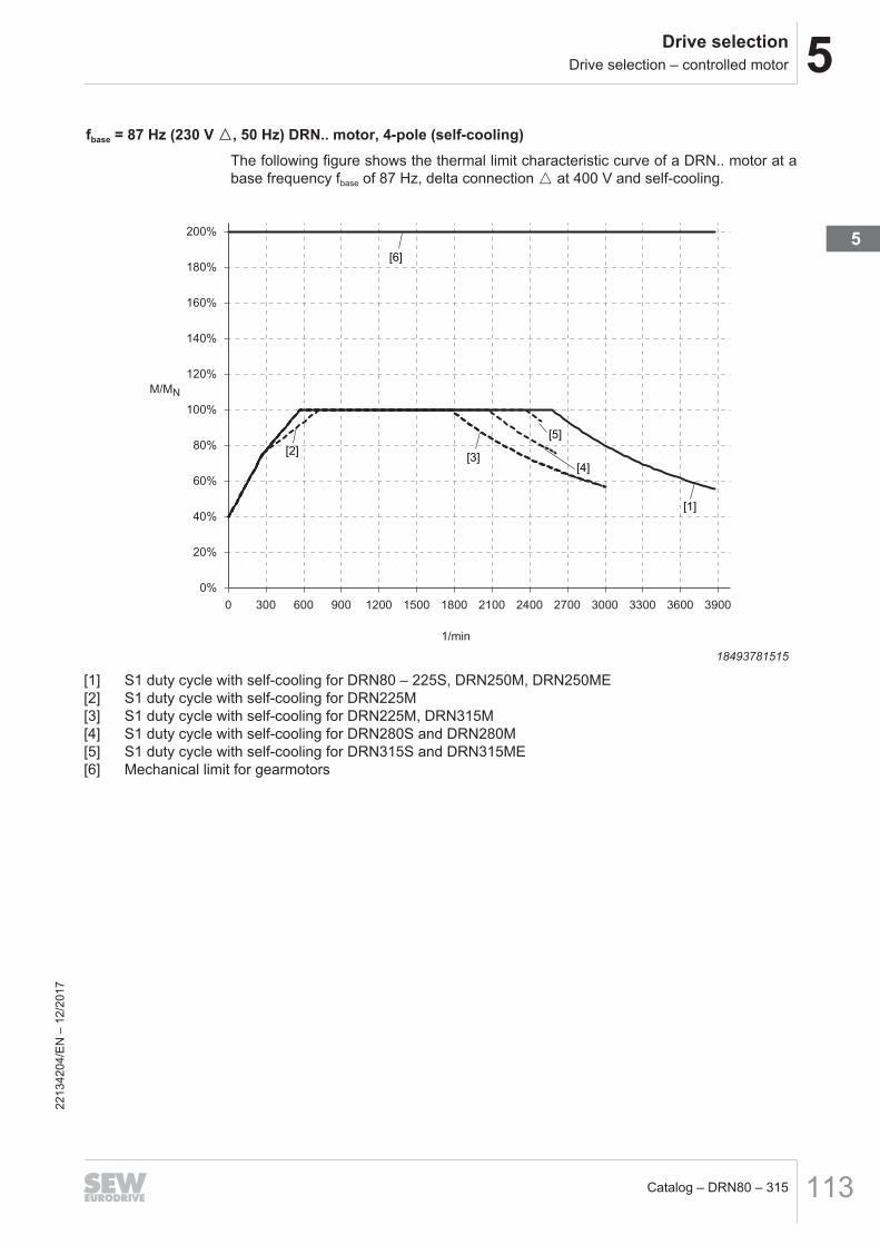
fbase = 87 Hz (230 V m, 50 Hz) DRN.. motor, 4-pole (self-cooling)The following figure shows the thermal limit characteristic curve of a DRN.. motor at abase frequency fbase of 87 Hz, delta connection m at 400 V and self-cooling.
0%
20%
40%
60%
80%
100%
120%
140%
160%
180%
200%
0 300 600 900 1200 1500 1800 2100 2400 2700 3000 3300 3600 3900
[6]
[3]
[1]
[4]
[5]
[2]
M/MN
1/min
18493781515
[1] S1 duty cycle with self-cooling for DRN80 – 225S, DRN250M, DRN250ME[2] S1 duty cycle with self-cooling for DRN225M[3] S1 duty cycle with self-cooling for DRN225M, DRN315M[4] S1 duty cycle with self-cooling for DRN280S and DRN280M[5] S1 duty cycle with self-cooling for DRN315S and DRN315ME[6] Mechanical limit for gearmotors
2213
4204
/EN
– 1
2/20
17
5

5 Drive selectionDrive selection – controlled motor
Catalog – DRN80 – 315114
fbase = 87 Hz (230 V m, 50 Hz) DRN.. motor, 4-pole (external cooling)The following figure shows the thermal limit characteristic curve of a DRN.. motor at abase frequency fbase of 87 Hz, delta connection m at 230 V and external cooling (op-tion forced cooling fan /V).
0%
20%
40%
60%
80%
100%
120%
140%
160%
180%
200%
0 300 600 900 1200 1500 1800 2100 2400 2700 3000 3300 3600 3900
[5]
[2] [1]
[4][3]
M/MN
1/min
18493783947
[1] S1 duty cycle with external cooling for DRN80 – 132S[2] S1 duty cycle with external cooling for DRN225M, DRN280S, DRN280M, DRN315M, DRN315L[3] S1 duty cycle with external cooling for DRN225S, DRN250ME, DRN250M, DRN315S, DRN315ME[4] S1 duty cycle with external cooling for DRN132M – 200L[5] Mechanical limit for gearmotors
2213
4204
/EN
– 1
2/20
17

5Drive selectionElectrical properties
Catalog – DRN80 – 315 115
5.4 Electrical properties5.4.1 Frequencies and voltagesFrequencies The AC motors from SEW‑EURODRIVE are delivered suitable for line frequency oper-
ation of 50 Hz or 60 Hz, depending on the configuration. The nameplates of the relev-ant motors list data referring to the configuration, see chapter "DRN.. AC motor typedesignation" (→ 2 48)The global motor design is an exception to that. It is designed for operation on a 50 Hzsupply system, as well as on a 60 Hz supply system. The nameplates of global motorslist information for operation at a 50 Hz supply system, as well as information for oper-ation at a 60 Hz supply system.Unless otherwise specified, the technical specifications in this catalog refer to motorsoperated at a line frequency of 50 Hz.
Voltages Depending on the configuration, AC motors from SEW‑EURODRIVE are designed foroperation at a fixed voltage (e.g. 230 V m/400 V W) or for operation in a voltage range(e.g. 220 V – 230 V m/380 V – 400 V W), see chapter "DRN.. AC motor type designa-tion" (→ 2 48).The following combinations of rated frequency and nominal voltage are possible:• Fixed voltage 50 Hz• Fixed voltage 60 Hz• 50 Hz voltage range• 50/60 Hz voltage rangeThe tolerances A and B as specified in standard IEC 60034 apply to rated frequen-cies, as well as to nominal voltages, see chapter "Tolerances according toIEC 60034-1" (→ 2 117).The AC motors from SEW‑EURODRIVE are available in a variety of nominal voltages.Should you require a nominal voltage deviating from the local standard, contactSEW‑EURODRIVE.
2213
4204
/EN
– 1
2/20
17
5

5 Drive selectionElectrical properties
Catalog – DRN80 – 315116
5.4.2 Standard nominal voltages at 50 Hz, or 50/60 Hz depending on the motor sizeAs standard, motors in the variants 50 Hz or 50/60 Hz are operated in the wiring dia-gram R13, i.e. in star or delta connection.The nominal voltage assigned to the motors by SEW‑EURODRIVE as standard variesdepending on the motor size and motor power.The following tables list the nominal voltages for motors designed for operation at a50 Hz or 50/60 Hz supply system depending on the rated power.
Motor Powerrating
Fixed voltage 50 Hz Voltage range 50 Hz Voltage range 50/60 Hz
kW V V VDRN80M –DRN132S
0.75 – 5.5 230m/400W 220-230m/380 – 400W 220 – 230m/380 – 400W,50 Hz
254 – 266m/440 – 460W,60 Hz
DRN132M –DRN315H
7.5 – 200 400m/690W 380-400m/660 – 690W 380 – 400m/660 – 690W,50Hz
440 – 460m/ – , 60 Hz
Due to the tolerances A and B as specified in standard IEC 60034, motors and brakesfor AC 230/400 V and motors for AC 400/690 V can also be operated at AC 220/380 Vor AC 380/660 V supply systems.
5.4.3 Nominal data of a 50 Hz motor when operated on a 60 Hz supply systemObserve the following table when motors designed for 50 Hz supply system are oper-ated on 60 Hz supply systems:
Nominal voltage at50 Hz
Connec-tion
Motor voltageat 60 Hz
Deviating dataRota-tionalspeed
Powerrating
Rated torque Starting torqueratio
AC 230 m/400 V W m 230 +20% 0% -17% -17%
AC 230 m/400 V W W460 +20% +20% 0% 0%
AC 400 m/690 V W m
If you want to operate motors designed for 50 Hz supply systems on a 60 Hz supplysystem, consult SEW‑EURODRIVE. In some countries and regions regulations applyregarding efficiency values that must be adhered for 60 Hz operation.
5.4.4 Motor properties for operation on a 60 Hz or 50/60 Hz supply systemThe motors are also available for operation at a line frequency of 60 Hz.In such cases, the length (and thus the geometric dimensions) a the same ratedpower may vary between the 50 Hz and the 60 Hz or 50/60 Hz design. Especially ad-here to this when selecting global motors, see chapter "Technical data of the mo-tors" (→ 2 52).
2213
4204
/EN
– 1
2/20
17
5Drive selectionTolerances according to IEC 60034-1
Catalog – DRN80 – 315 117
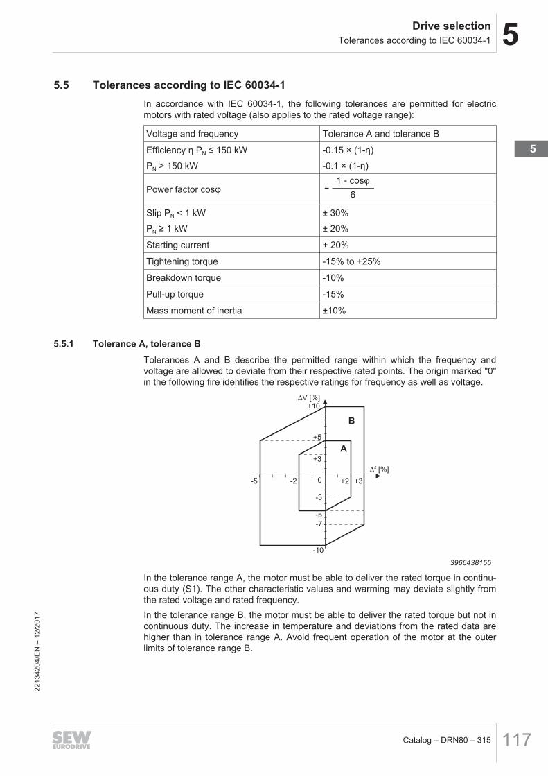
5.5 Tolerances according to IEC 60034-1In accordance with IEC 60034‑1, the following tolerances are permitted for electricmotors with rated voltage (also applies to the rated voltage range):
Voltage and frequency Tolerance A and tolerance B
Efficiency η PN ≤ 150 kWPN > 150 kW
-0.15 × (1-η)-0.1 × (1-η)
Power factor cosφ -1 - cos
6
ϕ
Slip PN < 1 kWPN ≥ 1 kW
± 30%± 20%
Starting current + 20%
Tightening torque -15% to +25%
Breakdown torque -10%
Pull-up torque -15%
Mass moment of inertia ±10%
5.5.1 Tolerance A, tolerance BTolerances A and B describe the permitted range within which the frequency andvoltage are allowed to deviate from their respective rated points. The origin marked "0"in the following fire identifies the respective ratings for frequency as well as voltage.
∆f [%]
∆V [%]
-5 -2
+10
+5
+3
-5
-3
+3+2
-7
0
-10
B
A
3966438155
In the tolerance range A, the motor must be able to deliver the rated torque in continu-ous duty (S1). The other characteristic values and warming may deviate slightly fromthe rated voltage and rated frequency.In the tolerance range B, the motor must be able to deliver the rated torque but not incontinuous duty. The increase in temperature and deviations from the rated data arehigher than in tolerance range A. Avoid frequent operation of the motor at the outerlimits of tolerance range B.
2213
4204
/EN
– 1
2/20
17
5

5 Drive selectionTolerances according to IEC 60034-1
Catalog – DRN80 – 315118
5.5.2 UndervoltageIt is not possible to achieve the rated value such as power, torque and speed in theevent of undervoltage e.g. due to weak supply systems or an insufficiently large motorcable. This is particularly true for motor startup where the starting current amounts to amultiple of the rated current.
5.5.3 OvervoltageOvervoltage results in a higher torque development, but also in more intense heatingof the motor winding.Overvoltages exceeding the tolerances permitted in the standards may cause damageat the motor winding.
2213
4204
/EN
– 1
2/20
17

5Drive selectionThermal classes according to IEC 60034-1
Catalog – DRN80 – 315 119
5.6 Thermal classes according to IEC 60034-1The motor standards of the IEC 60034-1 series describe the designs and identificationof thermal classes. This defines the limit overtemperatures for the winding subject tothe rated torque at a maximum ambient temperature of +40 °C. A thermal reserve of10 – 15 Kelvin for eventual voltage tolerances is also provided.SEW‑EURODRIVE indicated the thermal class of the motor with the numerical valueas required in the standards and with a letter.As standard, asynchronous motors from SEW‑EURODRIVE are designed in thermalclass 130 (B). Higher thermal classes (155 (F) and 180 (H)) are available upon re-quest.
Thermal classification/thermal class
Maximum winding temperature
130 (B) 130 °C
155 (F) 155 °C
180 (H) 180 °C
5.6.1 Power reductionThe rated power PN of a motor depends on the ambient temperature and the altitude.The rated power stated on the nameplate applies for an ambient temperature of 40 °Cand a maximum installation altitude of 1000 m above sea level. The power must be re-duced according to the following formula in the case of higher ambient temperaturesor altitudes:
PNred= PN × fT × fH
The following diagrams show the power reduction depending on the ambient tempera-ture and the installation altitude.The factors fT and fH apply for the motors:
1000 2000 3000 4000 H [m]
0.6
0.7
1.0
fH
30 40 50 60 T [°C]
fT
0.7
0.8
0.9
1.0
0.5
0.8
0.9
50000
9007207957178763
T Ambient temperatureH Installation altitude above sea levelPlease contact SEW‑EURODRIVE for ambient temperatures over 60 °C or installationaltitudes above 5000 m.
2213
4204
/EN
– 1
2/20
17
5

5 Drive selectionThermal classes according to IEC 60034-1
Catalog – DRN80 – 315120
5.6.2 Starting frequencyAt the supply system, a motor is rated according to its thermal capacity utilization incontinuous duty (S1 = continuous duty = 100% cyclic duration factor).
Definition The switching frequency indicates the number of times the motor can accelerate themass moment of inertia of its rotor and the moment of the external load up to the staticload speed without thermal overloading.The power demand calculated from the load torque of the application must not exceedthe rated power of the motor. This mechanical power must be output continuously bythe motor within the permitted thermal limits without overheating.
High switching frequencyIn practice, drives can be loaded in such a way that the motor can often be switchedon and off at low load torque relative to the motor's rated torque, such as for a traveldrive. In this case, it is not the power demand of the drive train that is the decisivefactor in determining the size of the motor, but rather the number of times the motorhas to start up per time interval.In comparison to motor operation at the rating point, a higher current flows at the start-up of an asynchronous motor. This starting current is specified in the starting currentratio. The motor heats up more during start-up due to the higher current than in per-manent operation at the rating point. This means each start-up leads to disproportion-ate heating of the motor.If the resulting heat is higher than the heat that is dissipated by the cooling system, thewindings can excessively overheat. This must be taken into account when configuringthe overall drive and is determined via the permitted switching frequency. The thermalload capacity of the motor can additionally be increased by selecting a suitablethermal class or by means of forced air cooling.
No-load starting frequency Z0
For line-powered drives, the thermal limit limits the permitted switching frequency ofthe motors. The basis for calculating the permitted switching frequency is the so-calledno-load starting frequency Z0 of the motors with the switch-ons per hour as the unit.SEW‑EURODRIVE specifies the permitted switching frequency of a load-free motor asthe no-load starting frequency Z0 at 50% cyclic duration factor. This value indicates thenumber of times per hour that the motor can accelerate the mass moment of inertia ofits rotor up to the rated speed without external load at 50% cyclic duration factor withinits thermal configuration.The calculation of the permitted switching frequency is based on the no-load startingfrequency, taking several influence factors into account. The following factors influ-ence the value of the no-load starting frequency:• KJ: The factor KJ is determined according to the mass moments of inertia to be ac-
celerated of the application and the motor options in relation to the inertia of themotor. The higher the additional mass moment of inertia to be accelerated, thesmaller the value KJ.
• KM: Depending on the external load during run-up, i.e. the higher the static loadtorque, the smaller the factor KM.
• KP: Depending on the static power and the relative cyclic duration factor cdf, i.e.the static capacity utilization and the percentage of the cyclic duration factor influ-ence the factor KP.
2213
4204
/EN
– 1
2/20
17
5Drive selectionThermal classes according to IEC 60034-1
Catalog – DRN80 – 315 121
Permitted switching frequency of motorsIf a load with increased mass moment of inertia has to be accelerated or an increasedload torque has to be overcome, the motor's run-up time increases. As a higher cur-rent flows during this run-up time, the motor is thermally more loaded and the permit-ted switching frequency decreases.You can determine the permitted switching frequency Z of the motor in cycles/hour us-ing the following formula:Z = Z0× KJ× KM× KP
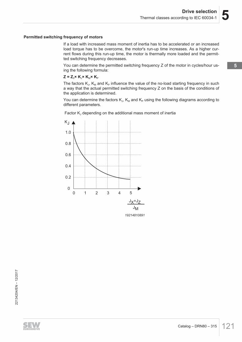
The factors KJ, KM and KP influence the value of the no-load starting frequency in sucha way that the actual permitted switching frequency Z on the basis of the conditions ofthe application is determined.You can determine the factors KJ, KM and KP using the following diagrams according todifferent parameters.
Factor KJ depending on the additional mass moment of inertia
1.0
0.8
0.6
0.4
0.2
0
0 1 2 3 4 5
JX+JZ
JM
KJ
19214810891
2213
4204
/EN
– 1
2/20
17
5
5 Drive selectionThermal classes according to IEC 60034-1
Catalog – DRN80 – 315122
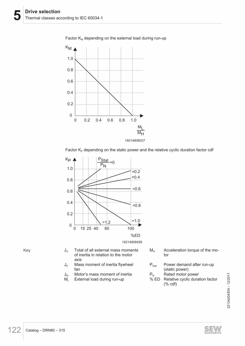
Factor KM depending on the external load during run-up
KM
ML
MH
1.0
0.8
0.6
0.4
0.2
0
1.00.80.60.40.20
19214806027
Factor KP depending on the static power and the relative cyclic duration factor cdf
=1.0
=0.8
=0.6
=0.4
=0.2
PStatPN
=0
=1.2
100604025150
1.0
0.8
0.6
0.4
0.2
0
%ED
KP
19214808459
Key JX Total of all external mass momentsof inertia in relation to the motoraxis
MH Acceleration torque of the mo-tor
JZ Mass moment of inertia flywheelfan
PStat Power demand after run-up(static power)
JM Motor’s mass moment of inertia PN Rated motor powerML External load during run-up % ED Relative cyclic duration factor
(% cdf)
2213
4204
/EN
– 1
2/20
17

5Drive selectionThermal classes according to IEC 60034-1
Catalog – DRN80 – 315 123
Example: Calculating the permitted switching frequency
Brakemotor: DRN80M4 with BE1 brake as line-powered driveNo-load starting frequency Z0 with BGE brake rectifier = 8200 h-1
1. (JX + JZ) / JM = 3.5 → KJ = 0.22. ML / MH = 0.6 → KM = 0.43. PStat / PN = 0.6 and 60% cdf → KP = 0.65
Z = Z0 × KJ × KM × KP = 8200 h-1 × 0.2 × 0.4 × 0.65 = 426 h-1
The cycle duration is 8.45 s.The switch-on time amounts to 5.07 s.In addition, it must be checked if the brake is permitted for the required operating con-ditions. Observe the information in the manual "Project Planning for BE.. Brakes –DR.., DRN.., EDR.., and EDRN.. AC Motors – Standard Brake/Safety Brake".
2213
4204
/EN
– 1
2/20
17
5

5 Drive selectionThermal monitoring
Catalog – DRN80 – 315124
5.7 Thermal monitoringIn accordance with the standard IEC 60034-11, two fundamental states are taken intoaccount when monitoring a motor against thermal overload:• Thermal overload with gradual temperature change• Thermal overload with rapid temperature change
5.7.1 Thermal overload with gradual temperature changeIf the motor is subject to thermal overload with a gradual temperature rise, the thermalprotection system must limit the winding temperature from critical rising.Possible causes for heating:• Failure of the cooling system, e.g. due to residue in the cooling channels or at the
cooling fins on the motor housing.• Reduced flow of cooling air, e.g. due to completely or partially covered fan grille.• Renewed drawing in of already heated cooling air.• Excessive rise in the ambient temperature or the coolant temperature.• Rising mechanical overload.• Voltage drop, overvoltage or asymmetry in the motor supply over an extended
period.• A cyclic duration factor deviating from the initial specifications at a motor dimen-
sioned for intermittent duty.• Deviations from the rated frequency.
5.7.2 Thermal overload with rapid temperature changeIf the motor is subject to thermal overload with a rapid temperature rise, the thermalprotection system must limit the winding temperature from rising further.Possible causes the rapid heating:• Rotor blockage.• Phase failure.• Start-up under special, non-designated conditions, e.g. with excess mass moment
of inertia, insufficient voltage or extremely high load torque.• Rapid load increase.• Repeated start-up over short time intervals.
2213
4204
/EN
– 1
2/20
17

5Drive selectionThermal monitoring
Catalog – DRN80 – 315 125
5.7.3 Determining the correct protection deviceSelecting the correct motor protection devices significantly influences the operationalsafety of the motor. There are 2 kinds of protection device current-controlled and mo-tor temperature-dependent.Current-controlled protection devices are usually installed in the control cabinet.Examples for current-controlled protection devices are:• Fuses• Motor circuit breakerTemperature-dependent protection devices are usually installed directly in the motorwinding.PTC thermistors, bimetallic switches, or temperature sensors respond when the max-imum permitted winding temperature is reached. The advantage is that temperaturesare recorded where they actually occur and reach the highest values.SEW-EURODRIVE provides four fundamental types of thermal motor protection forthe motors:• PTC thermistor /TF, chapter "PTC thermistor" (→ 2 390)• Bimetallic temperature switch /TH, chapter "Temperature switch" (→ 2 392)• Platinum temperature sensor /PT, chapter "Temperature sensor /PT" (→ 2 394)• Platinum temperature sensor /PK, chapter "Temperature sensor /PK" (→ 2 395)
FusesFuses do not protect the motor from overload, but are used to protect supply cables.They are exclusively used as short-circuit protection and may detect a rotor blockage,as this condition is similar to a short-circuit on the terminals.
Motor circuit breakersMotor circuit breakers offer adequate protection against overload in operation with lowswitching frequencies and brief start-ups. The motor circuit breaker is set to the ratedmotor current. In combination with DRN.. motors, ensure that the motor circuit break-ers used are suitable for IE3 motors.Motor circuit breakers are not adequate as the sole means of protection given switch-ing operation with a high switching frequency (> 60 per h) and for high inertia starting.In these cases we recommend to use PTC thermistors in addition, see chapter "PTCthermistor" (→ 2 390).
2213
4204
/EN
– 1
2/20
17
5
5 Drive selectionThermal monitoring
Catalog – DRN80 – 315126
PTC thermistorsThree PTC thermistors (PTC, characteristic curve according to DIN 44082) are integ-rated into the winding overhang of the motor and connected in series. The terminalsare in the terminal box.Evaluation takes place at a respective input of the inverter or at a trip switch in thecontrol cabinet.Motor protection with PTC thermistor /TF (see chapter "PTC thermistor" (→ 2 390))provide comprehensive protection against thermal overload. Motors protected in thisway can be used for heavy starting, switching and braking operation and in case ofunstable supply systems. A motor circuit breaker is usually installed as well.SEW‑EURODRIVE recommends using motors equipped with PTC thermistor for in-verter operation.
Bimetallic switchesThree bimetallic switches are integrated into the winding overhang of the motor andconnected in series, see chapter "Temperature switch" (→ 2 392). The terminals arein the terminal box.In contrast to the PTC thermistors, bimetallic switches do not require specific evalu-ation electronics. They can be directly included into the monitoring circuit of the motor.To achieve maximum motor protection, the trigger temperature is slightly lower thanthe limit value of the thermal class selected for the motor.
Platinum temperature sensorA platinum temperature sensor is integrated into the winding of the motor, see chapter"Temperature sensor /PK" (→ 2 395). Via the characteristic curve of the sensor, thewinding temperature of the motor can be constantly determined with an evaluationunit.The platinum sensor has an almost linear characteristic curve and a high level of ac-curacy.The platinum sensors do not bear any relation to the selected thermal class of the mo-tor and can be integrated into the winding in addition to a PTC thermistor or a bimetal-lic switch.
MOVIMOT® protection devices
MOVIMOT® protection devicesMotors driven by MOVIMOT® contain integrated protection devices to prevent thermaldamage. No other devices are required for motor protection.
2213
4204
/EN
– 1
2/20
17

5Drive selectionThermal monitoring
Catalog – DRN80 – 315 127
5.7.4 Comparison of the safety mechanismsThe following tables show the suitability of the various protection devices and temper-ature sensors for different causes of tripping.
Cause of the increasedthermal load
Current-dependentprotection device
Temperature-dependent protection device
Fuse Motorcircuit
breakers
PTCthermistor
/TF
Bimetallicswitch
/TH
Platinumtempera-
ture sensor /PT1)
Platinumtempera-
ture sensor /PK1)
Overcurrents up to 200% IN – x x x x x
Heavy start – • x • • •
Direct switching of the directionof rotation – • x • – –
Switching operation up toZ = 30 1/h
– • x x – –
Stalling • • • • • •
Phase failure – • x x – –
Voltage deviation (> tolerance B) – x x x x x
Frequency deviation (> tolerance B) – x x x x x
Insufficient motor cooling – – x x x x1) With adapted evaluation unit
x Comprehensive protection• Limited protection– No protection
2213
4204
/EN
– 1
2/20
17
5

5 Drive selectionOutput designs
Catalog – DRN80 – 315128
5.8 Output designsAsynchronous motors from SEW‑EURODRIVE are available in different flange- andfoot-mounted designs. This chapter provides a list of the available designs.In the standard version, the output shaft is designed as IEC shaft end with full key orhalf key.AC motors from SEW‑EURODRIVE are equipped with a pinion shaft end for directmounting to gear units.
5.8.1 /FI – IEC foot-mounted motorThe /FI foot-mounted motor is a motor design with drive-end endshield (closed flange),shaft end and feet pursuant to IEC 60072-1/EN 50347 (comparable to IEC basicmounting position IM B3). The dimension of the feet and the shaft end are shown onthe nameplate. This ensures a reference to the geometrical dimensions given inEN 50347.
5.8.2 /F.A, /F.B – Universal foot-mounted motorThese designs describe the SEW‑EURODRIVE motor in the universal foot version.This means that variable mounting of the feet to the stator is possible, thus allowing afoot-mounted motor with individual terminal box position (0°, 180°, 270°) to be imple-mented, e.g. /FIA or /FYB. The option /F.A means that the motor feet are enclosed inthe delivery, option /F.B means that the motor feed are mounted at the factory.
5.8.3 /FF – IEC flange-mounted motor with through boresFlanges of design /FF have through bores according to IEC 60072-1/EN 50347 (com-parable to IEC basic mounting position IM B5). Both the flange diameter and the dia-meter at which the bores are arranged as well as the shaft end comply with the spe-cifications of the standard.
5.8.4 /FT – IEC flange-mounted motor with threadsFlanges of design /FT have threaded holes according to IEC 60072-1/EN 50347 (com-parable to IEC basic mounting position IM B14). Both the flange diameter and the dia-meter at which the threads are arranged as well as the shaft end comply with the spe-cifications of the standard.
5.8.5 /FL – Flange-mounted motor (deviating from IEC)The flange design /FL has through bores or tapped holes according to the standard(comparable to IEC basic mounting position IM B14 or IM B5) according toIEC 60072-1/EN 50347. One or several geometrical designs deviate from the stand-ard. This may include: Other connection dimensions as defined in the size-to-powerrelationship, deviating flange heights or deviating alignment of the connection borepattern.
5.8.6 /FE – IEC flange-mounted motor with through bores and IEC feetCombination of /FI and /FF (comparable with IEC basic mounting position IM B35).
5.8.7 /FY – IEC flange-mounted motor with threaded holes and IEC feetCombination of /FI and /FT (comparable with IEC basic mounting position IM B34).
2213
4204
/EN
– 1
2/20
17

5Drive selectionOutput designs
Catalog – DRN80 – 315 129
5.8.8 /FK – Flange-mounted motor (deviating from IEC) with IEC feetCombination of /FI and /FL.
5.8.9 /FC – C-face flange-mounted motor, dimensions in inches according to NEMA MG1Shaft end and flange in /FC design are designed according to NEMA MG 1 (compar-able to IEC basic mounting position IM B14) and the dimensions are based on theAnglo-American system of measurement (inches).
5.8.10 /FG – Integral motor as stand-alone motorFlanges in /FG design are intended for connecting motors and gear units fromSEW‑EURODRIVE. The designation /FG is only part of the type designation if the mo-tors are delivered without gear unit.
5.8.11 /FM – Integral motor as stand-alone motor with IEC feetCombination of /FI and /FG (not comparable with an existing IEC basic mounting posi-tion).
5.8.12 OverviewThe table below gives an overview of the possible flange and feet designs.
OptionIEC flange IEC flange Non-IEC
flangeC-Face flange IEC foot Gear unit
flangeWith throughbore
With tappedhole
/FI
/FF
/FE
/FT
/FY
/FC
/FG
/FM
/FL
/FK
2213
4204
/EN
– 1
2/20
17
5

5 Drive selectionInput side shaft end
Catalog – DRN80 – 315130
5.9 Input side shaft endIn the standard design, the input side shaft end (A-side) of an AC motor fromSEW‑EURODRIVE is designed with keyway according to EN 50347 and full key ac-cording to DIN 6885. The shaft ends can also be delivered smooth and without a keyand keyway on request.A special form of input side shaft end for direct mounting to gear units fromSEW‑EURODRIVE is the pinion shaft end that represents the input element for thegear unit.Rotors are balanced with a half key as standard, see chapter "Vibrationclass" (→ 2 145).Contact SEW‑EURODRIVE if you need the motors to be delivered with rotors with full-key balancing (deviating from the standard). Rotors balanced in this manner arelabeled with a "V" on the front shaft end face in line with the standard regulations.The following table lists the standard shaft ends for DRN.. motors. Deviating geomet-ries of the shaft ends are available on request.
Motor Shaft endDRN80 19 × 40
DRN90 24 × 50
DRN100 28 × 60
DRN112 28 × 60
DRN132 38 × 80
DRN160 42 × 110
DRN180 48 × 110
DRN200 55 × 110
DRN225 60 × 140
DRN250 65 × 140
DRN280 75 × 140
DRN315 80 × 170
5.9.1 Center of gravity of motorsThe center of gravity of a motor is a theoretical variable. It is determined under the as-sumption that the entire mass of the motor is concentrated in one point and acts onthis point with the weight Fq. The mass of the motor can be found in the chapter "Tech-nical motor data".The center of gravity is relative to the flange position and stated with regard to thestandard IEC flange (B5). For brakemotors, it additionally considers the characteristicsof the BE.. brake assigned in the standard.Also consider the center of gravity for the combination of motors that are mounted to agear unit with an adapter.
2213
4204
/EN
– 1
2/20
17

5Drive selectionInput side shaft end
Catalog – DRN80 – 315 131
Changed designs or additional options influence the center of gravity. ConsultSEW‑EURODRIVE in case of deviating motor designs or changed options.
S
Fq
S
Fq
Motor Center of gravity S Brakemotor Brake Center of gravity Smm mm
DRN80MS 1141) DRN80MS BE1 1321)
DRN80M 1151) DRN80M BE1 1441)
DRN90S 1191) DRN90S BE2 1471)
DRN90L 1331) DRN90L BE2 1611)
DRN100LS 127 DRN100LS BE5 156DRN100L 152 DRN100L BE5 180DRN100LM 148 DRN100LM BE2 171DRN112M 161 DRN112M BE5 188DRN132S 180 DRN132S BE11 226DRN132M 187 DRN132M BE11 234DRN132L 199 DRN132L BE20 261DRN160M 218 DRN160M BE20 283DRN160L 233 DRN160L BE20 289DRN180M 232 DRN180M BE30 298DRN180L 244 DRN180L BE30 303DRN200L 294 DRN200L BE32 348DRN225S 262 DRN225S BE32 312DRN225M 262 DRN225M BE32 312DRN250M 325 DRN250M BE62 388DRN280S 337 DRN280S BE62 393DRN280M 377 DRN280M BE62 431DRN315S 408 DRN315S BE122 475DRN315M 414 DRN315M BE122 478DRN315L 464 DRN315L BE122 535DRN315H 488 DRN315H BE122 5501) Plastic fan guard
5.9.2 Special shaft endsSEW‑EURODRIVE can also deliver shaft ends of the solo foot-mounted motors and/orsolo flange-mounted motors that differ from the series design. ContactSEW‑EURODRIVE, if required.The permitted overhung and axial loads and the dimensions of the special shaft endare documented separately. Observe the following chapter for the standard IEC shaftends and bearings.
2213
4204
/EN
– 1
2/20
17
5

5 Drive selectionInput side shaft end
Catalog – DRN80 – 315132
5.9.3 Overhung and axial loads for motor shaft endsYou can read the maximum permitted overhung load FRx of the respective motor de-pending on the point of force application relative to the shaft shoulder from the follow-ing diagrams.All overhung load diagrams depict the values for a statistical bearing service life of40 000 hours at the input side shaft end. A detailed bearing service life calculation isavailable on request.The following figure shows the point of force application of the overhung load FRx atpoint X.
l
x
FA
FRx
3980490891
l Length of the shaft endx Distance between overhung load application point and shaft shoulderFRx Maximum permitted overhung load at point of force applicationFA Maximum permitted axial load
The customer's overhung load FR always has to be less than or equal to the maximumpermitted overhung load FRX from the diagrams:FR ≤ FRX
2213
4204
/EN
– 1
2/20
17

5Drive selectionInput side shaft end
Catalog – DRN80 – 315 133
The following diagram shows an example of how you can read the maximum over-hung load from the diagram:
0
200
400
600
800
1000
1200
1400
0 10 20 30 40 50 60
x [mm]
FR
x [
N]
Ø14x30
Ø19x40
[1] [2]
[2]
[1]
9007203235233547
[1] Motor with shaft diameter 14 mm, force application x at 22 mm, maximum permitted overhung loadFRx = 600 N
[2] Motor with shaft diameter 19 mm, force application x at 30 mm, maximum permitted overhung loadFRx = 700 N
When determining the overhung load, a transmission element factor fZ must be con-sidered under certain conditions. This factor depends on the used transmission ele-ments, such as gear wheels, chains, V-belts, flat belts or toothed belts.When belt pulleys are used, the initial belt tension must be considered as well. In total,the overhung loads FR calculated with the transmission element factor must not ex-ceed the maximum permitted overhung load of the motor FRX.
Transmission element Transmission element factor fZ CommentsDirect drive 1.0 –
Gear wheels 1.0 ≥ 17 teeth
Gear wheels 1.15 < 17 teeth
Sprockets 1.0 ≥ 20 teeth
Sprockets 1.25 < 20 teeth
Narrow V-belt 1.75 Influence of pre-tensioning
Flat belt 2.50 Influence of pre-tensioning
Toothed belt 1.50 Influence of pre-tensioning
Gear rack 1.15 < 17 teeth (pinion)
The resulting customer overhung load is calculated using the following equation:FR × fz ≤ FRx
2213
4204
/EN
– 1
2/20
17
5

5 Drive selectionInput side shaft end
Catalog – DRN80 – 315134
The diagrams are summarized according to the motor size. The shaft ends availablefor the respective size are represented in one diagram.The information considers the rated speed nN and the higher-level rated torque MN forcontinuous duty (S1) of the motor.For other operating modes than S1 (e.g. S2, S3, etc.), the permitted values for FRx andFA have to be multiplied with the factor 0.8.FRx,switching operation = FRx × 0.8FA,switching operation = FA × 0.8If further application conditions occur which are not considered in the descriptions ordiagrams in this chapter, consult SEW‑EURODRIVE.
Permitted axial loadThe maximum permitted axial load FA is determined by multiplying the maximum per-mitted overhung load FRX with the factor 0.2.FA = 0.2 × FRx
2213
4204
/EN
– 1
2/20
17

5Drive selectionInput side shaft end
Catalog – DRN80 – 315 135
Overhung load diagrams
Key
2, 4, 6 Number of poles
Ø19x40 Shaft end
For overhung load diagrams of the second shaft end, refer to chapter "Second shaftend (B‑side)" (→ 2 383).
Overhung load diagram for DRN80
0
200
400
600
800
1000
1200
1400
0 10 20 30 40 50 60
Ø19X40
DRN80
FR
X [N
]
x [mm]
4
2
9007212717222923
Overhung load diagram for DRN90
0
500
1000
1500
2000
2500
0 10 20 30 40 50 60 70
Ø24X50
DRN90
FR
X [N
]
x [mm]
6
4
2
9007212717226763
2213
4204
/EN
– 1
2/20
17
5

5 Drive selectionInput side shaft end
Catalog – DRN80 – 315136
Overhung load diagram for DRN100
0
500
1000
1500
2000
2500
3000
0 10 20 30 40 50 60 70 80 90
Ø28X60
DRN100
FR
X [N
]
x [mm]
6
4
2
9007212717149963
Overhung load diagram for DRN112M – DRN132S
0
500
1000
1500
2000
2500
3000
3500
4000
4500
0 20 40 60 80 100 120
x [mm]
DRN112M – DRN132S
Ø28X60
Ø24X50
Ø38X80
FR
X [N
] 2
4
6
9007212717153803
2213
4204
/EN
– 1
2/20
17

5Drive selectionInput side shaft end
Catalog – DRN80 – 315 137
Overhung load diagram for DRN132M – DRN132L
0
1000
2000
3000
4000
5000
6000
0 20 40 60 80 100 120
x [mm]
DRN132M – DRN132L
Ø38X80
FR
X [N
]
6
4
9007212717196043
Overhung load diagram for DRN160
0
1000
2000
3000
4000
5000
6000
7000
0 20 40 60 80 100 120 140 160
x [mm]
DRN160
Ø42X110
Ø38X80
FR
X [N
]
6
4
9007212717199883
2213
4204
/EN
– 1
2/20
17
5

5 Drive selectionInput side shaft end
Catalog – DRN80 – 315138
Overhung load diagram for DRN180
0
1000
2000
3000
4000
5000
6000
7000
8000
0 20 40 60 80 100 120 140 160
x [mm]
DRN180
Ø48X110
FR
X [N
]
13462462731
Overhung load diagram for DRN200
0
1000
2000
3000
4000
5000
6000
7000
8000
9000
0 20 40 60 80 100 120 140 160
x [mm]
DRN200
Ø55X110
FR
X [N
]
13462466571
2213
4204
/EN
– 1
2/20
17

5Drive selectionInput side shaft end
Catalog – DRN80 – 315 139
Overhung load diagram for DRN225
0
2000
4000
6000
8000
10000
12000
0 5025 100 150 200
x [mm]
DRN225
Ø60X140
FR
X [N
]
75 125 175
13462470411
Overhung load diagram for DRN250 – DRN280
0
2000
4000
6000
8000
10000
12000
14000
16000
18000
20000
0 50 100 150 200
x [mm]
DRN250 – DRN280
Ø65X140Ø65X140 /ERFØ75X140Ø75X140 /ERFLimit foot AH 250
FR
X [N
]
25 75 125 175
13462474251
2213
4204
/EN
– 1
2/20
17
5

5 Drive selectionInput side shaft end
Catalog – DRN80 – 315140
Overhung load diagram for DRN315
0
5000
10000
15000
20000
25000
30000
35000
0 5025 100 150 200 250
x [mm]
DRN315
Ø80X170
Ø80X170 /ERF
FR
X [N
]
75 125 175 225
9007212717219083
2213
4204
/EN
– 1
2/20
17

5Drive selectionBearings
Catalog – DRN80 – 315 141
5.10 Bearings5.10.1 Bearing types used
The asynchronous motors are delivered with deep groove ball bearings of sizes 62..and 63.. with cover plate and bearing clearance C3 as standard. For brakemotors,bearings with shield rings are used on the B-side to prevent brake dust from entering.Depending on the selected options, the bearing selection can deviate from the stand-ard.
Motors A-side bearing B-side bearingIEC motor Gearmotor
DRN80 6205 6304 6304
DRN90 6305 6205
DRN100 6306 6205
DRN112 6308 6207
DRN132S 6308 6207
DRN132M/L 6308 6309 6209
DRN160 6310 6312 6212
DRN180 6311 6312 6212
DRN200 6312 6314 6314
DRN225 6314 6314
DRN250 63171) 6315
DRN280 63171) 6315
DRN315S 63192) 63192)
DRN315M 63192) 63192)
DRN315L 63192) 63222) 63192)
DRN315H 63192) 63222) 63192)
1) Bearing clearance C42) Without cover plate and shield ring
2213
4204
/EN
– 1
2/20
17
5

5 Drive selectionMaximum speeds
Catalog – DRN80 – 315142
5.11 Maximum speedsThe mechanical limit speeds of the motors depend on the site and are binding for op-eration on inverters. For limit speeds that have been configured differently, larger limitspeeds may be possible depending on the options. Contact SEW‑EURODRIVE insuch cases. The guide values for limit speeds are listed in the following tables:
Motors Maximum mechanical speed nmax in 1/minMotor Brakemotor Motor with backstop
DRN80 6000 4500 5000
DRN90 6000 3600 5000
DRN100 5200 3600 5000
DRN112 5000 3600 4500
DRN132S 5000 3600 4500
DRN132M/L 4500 3600 4500
DRN160 4500 3600 4500
DRN180 4000 3600 4000
DRN200 3500 25001) 3500
DRN225 3100 25001) 3100
DRN250 2600 2500 2600
DRN280 2600 2500 2600
DRN315 2500 2500 25001) For brakemotors with BE30 or BE32: refer to motor without brake
Brakemotors Also observe to the following points for brakemotors:• The applicable drive selection regulations with regard to the braking work, see
manual "Project Planning for BE.. Brakes – DR.., DRN.., EDR.., and EDRN..AC Motors – Standard Brake/Safety Brake".
• Braking from speeds > 1800 1/min is not permitted for brake sizes BE30 – BE122for every application. Observe the project planning procedure and the application-specific maximum speeds for braking operations in manual "Project Planning forBE.. Brakes – DR.., DRN.., EDR.., and EDRN.. AC Motors – Standard Brake/Safety Brake". Use the controller to reduce the speed before activating the mech-anical brake.
Backstop For motors with backstop, observe that the backstop can only be operated wear-freeabove its lift-off speed due to its operating principle. Observe chapter "Mechanicalbackstop" (→ 2 416).
Other motor op-tions
Additional motor options influence these speeds. Contact SEW‑EURODRIVE in suchcases.
2213
4204
/EN
– 1
2/20
17

5Drive selectionVentilation
Catalog – DRN80 – 315 143
5.12 VentilationIn the standard, asynchronous motors from SEW‑EURODRIVE are fan-cooled (ICcode 411). The fan is attached to the rotor shaft at the B-side of the motor. The im-pellers of the fan wheels generate the same air flow, irrespective of the direction of ro-tation. The intensity of the air flow depends on the motor speed. This means that thecooling capacity of the motor fan decreases with lower motor speeds (e.g. FI-con-trolled drives). For this reason, the rated motor torque cannot be taken off at smallspeeds without additional measures during continuous duty.The forced cooling fan option (/V) is available as another ventilation option, seechapter "Forced cooling fan" (→ 2 398). For this option, the fan wheel is removed fromthe rotor shaft and replaced by a cover with an integrated active fan. The forced cool-ing fan has to be supplied externally and thus is operation independent of the motorspeed, see also chapter "Limit characteristic curves of the motors in inverter opera-tion" (→ 2 111).To fulfill different application-related requirements, the fan wheels can have differentgeometries and can be made of different materials. In the standard version, the mo-tors are delivered with a plastic fan. They can be used in a temperature range of-20 °C to +60 °C. The technical data of the motors, e.g. the switching frequency or theinertia refer to the use of a plastic fan, see chapter "Technical data of the mo-tors" (→ 2 52).As an alternative, the fan wheels can also be made of aluminum or gray cast iron.When using other fan wheel materials, the properties of the drive will change. Observethe relevant conditions during drive selection and project planning. For detailed inform-ation on the different fan options, refer to chapters "Aluminum fan" (→ 2 402), "Addi-tional flywheel mass" (→ 2 403).In addition to the various ventilated options, asynchronous motors fromSEW‑EURODRIVE can also be delivered non-ventilated. You can choose between ahousing that is completely closed on the B-side and a design where the standard fanwheel is removed, see chapter "Non-ventilated motors" (→ 2 404). ConsultSEW‑EURODRIVE for configuration of non-ventilated motors.
5.12.1 Fan wheel materialThe impellers of the fan wheels are designed to create the same air flow independ-ently of the direction of rotation.To fulfill different application-related requirements, the fan wheels can have differentgeometries and can be made of different materials.
2213
4204
/EN
– 1
2/20
17
5

5 Drive selectionDegrees of protection according to IEC 60034-5
Catalog – DRN80 – 315144
5.13 Degrees of protection according to IEC 60034-5In the standard version, the DRN.. AC motors are designed in degree of protectionIP54 according to IEC 60034-5. Degrees of protection up to IP66 are available uponrequest. As an alternative, DRN.. motors can also be delivered in a basic design in de-gree of protection IP44.
Drive selection The required degree of protection must be selected with care. Otherwise there is a riskof damage due to dirt particles or water entering the motor. In addition, there is the op-tion to protect the drive against corrosion as well as aggressive ambient conditions,see chapter "Surface and corrosion protection" (→ 2 414).
Definition of degrees of protection according to IEC 60034-5
First characteristic numeral Second characteristic numeralShort description Short description
0 Unprotected machine 0 Unprotected machine
1 Machine protected against solid foreign ob-jects > 50 mm
1 Machine protected against dripping water
2 Machine protected against solid foreign ob-jects > 12 mm
2 Machine protected against dripping water atinclination of 15°
3 Machine protected against solid foreign ob-jects > 2.5 mm
3 Machine protected against spraying water
4 Machine protected against solid foreign ob-jects > 1 mm
4 Machine protected against splashing water
5 Machine protected against dust 5 Machine protected against water jets
6 Machine dust-tight 6 Machine protected against effects of roughseas
– – 7 Machine protected when immersing
– – 8 Machine protected when fully immersed
5.13.1 Labeling of degree of protection for global motorsSEW‑EURODRIVE classifies the motor degrees of protection according to the interna-tional standard IEC 60034-5.In North America, on the other hand, identification of a different degree of protectionused.The degree of protection and the type of cooling are represented with an abbreviationmade up of 4 letters. In the case of the global motor, SEW‑EURODRIVE employs thefollowing identifications and includes this information on the nameplate.
Abbre-viation
English designation German translation
TEFC Totally Enclosed Fan Cooled völlig geschlossen, Lüfter gekühlt
TEBC Totally Enclosed Blower Cooled völlig geschlossen, Fremdlüfter gekühlt
TENV Totally Enclosed Non Ventilated völlig geschlossen, unbelüftet
2213
4204
/EN
– 1
2/20
17

5Drive selectionVibration class and increased vibration stress
Catalog – DRN80 – 315 145
5.14 Vibration class and increased vibration stressIrrespective of the mount-on components on the B-side, AC motors fromSEW‑EURODRIVE fulfill the requirements for achieving vibration class A according toDIN EN 60034-14. If special requirements for the mechanical running smoothness ex-ist, motors without mount-on components (no brake, forced cooling fan, encoder, etc.)can be delivered in a low-vibration design in vibration class B. For this design, specialmeasures for balancing the rotors are carried out.For vibration classes A or B, the motor rotors are always dynamically balanced with ahalf key.
2213
4204
/EN
– 1
2/20
17
5

5 Drive selectionVibration class and increased vibration stress
Catalog – DRN80 – 315146
5.14.1 Design for increased vibration stressDuring the installation of the motors, make sure that the supports are even, the foot orflange mounting is solid and if there is direct coupling, align with precision. Avoid res-onances between the rotational frequency and the double network frequency causedby the structure or the positioning of the motor.If the installation of the drive cannot be ensured in accordance with the standard re-quirements by SEW‑EURODRIVE, the motors can be delivered in a design for in-creased vibration stress.Motors dimensioned for increased vibration stress achieve vibration stress level 1 (Vi-bration Level 1 = VL1). The values from the following table can be applied. The valuesare based on standardized information pursuant to DIN ISO 10816-1.
Motors Periodic vibrations Shock stress1g = 9.81 m/s²
DRN80MS – 132S Effective vibration speed ≤ 4.5 mm/s Maximum acceleration = 10 g
DRN132M – 315H Effective vibration speed ≤ 7.1 mm/s Maximum acceleration = 15 g
If you require a drive for which the required values exceed the information for VL1,please contact SEW‑EURODRIVE.The following design types and options for motors with increased vibration stress can-not be delivered:
Designation DesignationDiagnostic unit for function and wear monitoring of the brake
/DUE
Built-in encoder /EI7.
MOVIMOT® /MM
MOVISWITCH® /MSW
Plastic fan guard /LN
Additional inertia mass (flywheel fan) /Z
IEC foot-mounted motor1) /FI
Motors according to VIK guideline –
Thermal class 180 (H) –
Ambient temperature Tamb > 60 °C –
Double brake /BF, /BT
EDR../EDRN explosion-proof motors2)
1) Can be delivered from DRN132M upwards2) Can only be delivered upon consultation with SEW‑EURODRIVE.
2213
4204
/EN
– 1
2/20
17