dry and semi-dry centralized system · pdf filel/m 150 300 450 600 750 900 1050 1200 one-fan...
TRANSCRIPT

CATTANI S.p.A.
DRY AND SEMI-DRY CENTRALIZEDSYSTEM
• INSTRUCTIONS HANDBOOK

1
— INTRODUCTION ..............................................................................................— GENERAL FEATURES ....................................................................................— APPLIANCES DESCRIPTION— TURBO-JET modular .......................................................................................— MANUAL TIPS SUPPORTS ............................................................................— PNEUMATIC TIPS SUPPORTS ......................................................................— PNEUMATIC MANIFOLD ................................................................................— INSERTS .........................................................................................................— CANISTERS / AUTOMATIC MINI-SEPARATORS / SEPARATOR TANKS— SHUTTING VALVES .......................................................................................— AMALGAM SEPARATORS .............................................................................— DIN HYDROSEPARATOR AND HYDROCYCLONE ......................................— ISO HYDROSEPARATOR AND HYDROCYCLONE ......................................— SINGLE-FAN ASPIRATION UNITS ................................................................— TWO-FAN ASPIRATION UNITS ...................................................................— ACCESSORIES FOR ASPIRATION UNITS ....................................................— ELECTRICAL CONTROL PANELS .................................................................— PLANNING— ASPIRATING PIPINGS ...................................................................................— ELECTRICAL WIRINGS ..................................................................................— INSTALLATION— TIP SUPPORTS ..............................................................................................— CANISTERS AND SEPARATORS ..................................................................— SHUTTING VALVES .......................................................................................— AMALGAM SEPARATORS— AMALGAM SEPARATOR TRAP .....................................................................— HYDROSEPARATOR .....................................................................................— CONTROL PANELS AND ASPIRATION UNITS ............................................— OPERATION AND USE— DRY AND SEMI-DRY SYSTEMS ....................................................................— MAINTENANCE ...............................................................................................— ORDINARY MAINTENANCE OPERATIONS ..................................................— ANTIFOAMING TABLETS ..............................................................................— MAIN ORDINARY MAINTENANCE OPERATIONS ........................................— MAIN EXTRAORDINARY MAINTENANCE OPERATIONS RESERVED TO— DENTAL ENGINEERS ....................................................................................— IMPORTANT NOTICE .....................................................................................— TRANSPORT AND STORAGE ........................................................................— TRANSPORT OF SECOND-HAND APPLIANCES ..........................................
22
23333444556
101212
1212
131314
141415
1616171818
19192020
AIR AND SEMI-DRY CENTRALIZEDSYSTEMS(Handbook reserved to dental engineers)
EN
GL
ISH
PageCONTENTS
2
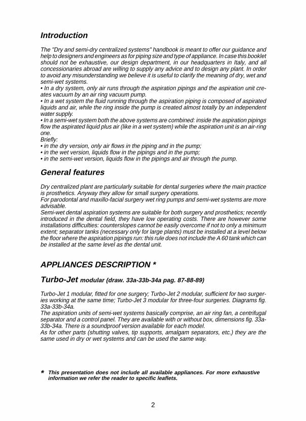
Introduction
The "Dry and semi-dry centralized systems" handbook is meant to offer our guidance andhelp to designers and engineers as for piping size and type of appliance. In case this bookletshould not be exhaustive, our design department, in our headquarters in Italy, and allconcessionaries abroad are willing to supply any advice and to design any plant. In orderto avoid any misunderstanding we believe it is useful to clarify the meaning of dry, wet andsemi-wet systems.• In a dry system, only air runs through the aspiration pipings and the aspiration unit cre-ates vacuum by an air ring vacuum pump.• In a wet system the fluid running through the aspiration piping is composed of aspiratedliquids and air, while the ring inside the pump is created almost totally by an independentwater supply.• In a semi-wet system both the above systems are combined: inside the aspiration pipingsflow the aspirated liquid plus air (like in a wet system) while the aspiration unit is an air-ringone.Briefly:• in the dry version, only air flows in the piping and in the pump;• in the wet version, liquids flow in the pipings and in the pump;• in the semi-wet version, liquids flow in the pipings and air through the pump.
General features
Dry centralized plant are particularly suitable for dental surgeries where the main practiceis prosthetics. Anyway they allow for small surgery operations.For parodontal and maxillo-facial surgery wet ring pumps and semi-wet systems are moreadvisable.Semi-wet dental aspiration systems are suitable for both surgery and prosthetics; recentlyintroduced in the dental field, they have low operating costs. There are however someinstallations difficulties: counterslopes cannot be easily overcome if not to only a minimumextent; separator tanks (necessary only for large plants) must be installed at a level belowthe floor where the aspiration pipings run: this rule does not include the A 60 tank which canbe installed at the same level as the dental unit.
APPLIANCES DESCRIPTION *
Turbo-Jet modular (draw. 33a-33b-34a pag. 87-88-89)
Turbo-Jet 1 modular, fitted for one surgery; Turbo-Jet 2 modular, sufficient for two surger-ies working at the same time; Turbo-Jet 3 modular for three-four surgeries. Diagrams fig.33a-33b-34a.The aspiration units of semi-wet systems basically comprise, an air ring fan, a centrifugalseparator and a control panel. They are available with or without box, dimensions fig. 33a-33b-34a. There is a soundproof version available for each model.As for other parts (shutting valves, tip supports, amalgam separators, etc.) they are thesame used in dry or wet systems and can be used the same way.
This presentation does not include all available appliances. For more exhaustiveinformation we refer the reader to specific leaflets.
*

3
EN
GL
ISH
TURBO-JET 1 modular TURBO-JET 2 modular TURBO-JET 3 modular
*
Tip supports
Manual tip supports.
Draw. 2
Draw. 1
Pneumatic and automatic tip supports.
Draw. 3
Pneumatic manifold.
Inserts for:1) mechanical terminal Ø 16 - 2) mechanical terminal Ø 11 - 3) micromotors4) Turbine and syringe - 5) composite lamp - 6) manual terminal Ø 117) manual terminal Ø 16.
Draw. 4
This appliance cannot work in the presence of an anaesthetic mixture inflammable withair, with oxygen or nitrogen protoxide.
*1 2 3 4 5 6 7

4
Draw. 5 Draw. 6 Draw. 7
Canisters / Automatic Mini-Separators / Separator tanks
Maxi-Canister: to be used in single-surgery installations, capacity 1.5 l, automaticdrainage with stop of aspiration, draw. 5.Automatic Mini-Separator with draining pump: to be used in single-surgery instal-lations, capacity 1.0 l, continuous running, draw. 6.Small Separator Tank (A 53): capacity 12.5 l, draw. 7; the tank is fitted with autoclavefor automatic washing, for 6 surgeries max.Medium Separator Tank (A 54): capacity 39 l, draw. 7; the tank is fitted with autoclavefor automatic washing, for 17 surgeries max.Large Separator Tank (A 57): capacity 130 l, draw. 7; the tank is fitted with autoclavefor automatic washing, for 54 surgeries max.
Draw. 8 Draw. 9 Draw. 10
Shutting valves
These valves are used to make independent from the others each surgery connectedto a centralized plant.Motorized electrovalve: usually coupled to the Maxi-Canister, is recommended for airring systems, draw. 8.Electropneumatic valve: as a rule it is coupled to the Mini-Separator and is recom-mended for dry and semi-dry systems, draw. 9.Mignon Electropneumatic valve: same features as the previous one, it is particularlyadvisable for the passage of liquids and disinfectants, draw. 10.
Amalgam separators *
Separator-tanks: perform separation by decantation.
Draw. 11
* Our amalgam separators are not always compatible with other manufacturer’s units.

5
Hydroseparator and Hydrocyclone type DIN: TÜV approved 97% separation rate,flow 3.5 l/min they are respectively suitable for dry and semi-dry systems, fig. 13-14.
Hydroseparator and Hydrocyclone type ISO: tested for 96.6% separation rate, flow5.5 l/min they are respectively suitable for dry and semi-dry systems, fig. 12a-12b.
Draw. 12a Draw. 12b
EN
GL
ISH
Draw. 13
Draw. 14
Draw. 14 b

6
mm
H2O
mm
Hg
500
1000
1500
2000
2500
20
40
60
80
100
120
140
160
180
psi
1
2
3
m b
ar
k pa
50 5
10
15
20
25250
200
150
100
g.p.m. (lmp.) 50 100 150 250
g.p.m. (U.S.) 50
200
100 150 200 250 300
m3/h 10 20 30 40 50 60 70 80
l/sec 5 10 15 20
l/m 150 300 450 600 750 900 1050 1200
One-fan aspiration units
Six models: Uni -Jet 75, Mini-Jet 2V, Tecno-Jet, Flux-Jet, Medio-Jet and Maxi-Jet 2S.They are suitable for centralized systems where the engine room is placed close or notvery far from the surgeries and where the demand is for an average head (about 900mm H2O). Deadening boxes and brackets for wall fixing are available for the foursmallest units. Table “A” (page 81) shows useful data for the choice of aspiration unitsand piping diameters related to the number of surgeries and to distance.
Uni-Jet 75, box and bracket
UNI-JET 75:(1 ) power output 0.4 kW - 3.1 A,maximum flow 1250 l/min,running maximum head for continuousservice 1300 mm H2O,sound pressure level 62 dB (A),single-surgery use.
UNI-JET 75 + BOX:sound pressure level 58 dB (A).
• This appliance cannot work in the presence of an anaesthetic mixture inflammable with air, with oxygen or nitrogen protoxide.• Sound pressure level tested with canalized air, according to ISO regulation 3746 -1979 (E). Parameters: r= 1 - Background noise < 51 dB (A) - Instrument Brüel & Kjær Type 2232.• Power output in kW is referred to 220-380 V tension.

7
g.p.m.(U.K. liquid) 100 200 300 500
g.p.m.(U.S. liquid) 90
400
180 270 450 540 630
600
720360
psi
1
2
3
m b
ar
k p
a
50 5
10
15
20
25250
200
150
100
m3/h 20 40 60 80 100 120 140 160
l/sec 10 20 30 40
l/m 300 600 900 1200 1500 2100 2400 27001800
mm
H2O
mm
Hg
500
1000
1500
2000
2500
20
40
60
80
100
120
140
160
180
m3/h 10 20 30 40 50 60 70 80
l/sec 5 10 15 20
l/m 150 300 450 600 750 1050 1200900
mm
H2O
mm
Hg
500
1000
1500
2000
2500
20
40
60
80
100
120
140
160
180
g.p.m.(U.K. liquid) 50 100 150 250
g.p.m.(U.S. liquid) 50
200
100 150 200 250 300
psi
1
2
3
m b
ar
k p
a
50 5
10
15
20
25250
200
150
100
Mini-Jet 2V, box and bracket
MINI-JET 2V:(1 ) power output 0.55 kW - 4.3 A,(3 ) Y 1.6 A - ∆ 2.8 A - 0.55 kW,maximum flow 980 l/min,running maximum head for continuousservice 1900 mm H2O,sound pressure level 62 dB (A),single surgery use.
MINI-JET 2V + BOX:sound pressure level 62 dB (A).
Tecno-Jet, box and bracket
TECNO-JET:(1 ) power output 0.75 kW - 5.5 A,(3 ) Y 1.95 A - ∆ 3.4 A - 0.75 kW,maximum flow 2000 l/min,running maximum head for continuousservice 1400 mm H2O,sound pressure level 67 dB (A),for 3 surgeries working at the same time.
EN
GL
ISH

8
mm
H2O
mm
Hg
500
1000
1500
2000
2500
20
40
60
80
100
120
140
160
180
g.p.m. (U.K. liquid) 125 250 375 750
g.p.m. (U.S. liquid) 110
500
220 330 440 550 770
l/sec 12,5 25 37,5 50
l/m 375 750 1125 1500 1875 2250 2625 3000
m3/h 25 50 75 100 125 150 175 200
3375
psi
1
2
3
m b
ar
k pa
50 5
10
15
20
25250
200
150
100
TECNO-JET + BOX:sound pressure level 60 dB (A).
Flux-Jet, box and bracket
FLUX-JET:(1 ) power output 1.1 kW - 7.6 A,(3 ) Y 3.7 A - ∆ 6.4 A - 1.5 kW,maximum flow 3300 l/min,running maximum head for continuousservice 1500 mm H2 O,sound pressure level 68.5 dB (A),for 4 surgeries working at the same time.
FLUX-JET + BOX:sound pressure level 63 dB (A).

9
g.p.m.(U.K. liquid) 200 400 600 1000
g.p.m.(U.S. liquid) 175
800
350 525 875 1050 1225
1200
1400700
psi
1,5
3
4,5
m b
ar
k p
a
75 7,5
15
22,5
30
37,5375
300
225
150
m3/h 40 80 120 160 200 240 280 320
l/sec 20 40 60 80
l/m 600 1200 1800 2400 3000 4200 4800 54003600
mm
H2O
mm
Hg
750
1500
2250
3000
3750
30
60
90
120
150
180
210
240
270
mm
H2O
mm
Hg
750
1500
2250
3000
3750
30
60
90
120
150
180
210
240
270
g.p.m.(U.K. liquid) 300 600 900 1500
g.p.m.(U.S. liquid) 260
1200
520 780 1300 1560 1820
1800
20801040
psi
1,5
3
4,5
m b
ar
k p
a
75 7,5
15
22,5
30
37,5375
300
225
150
m3/h 60 120 180 240 300 360 420 480
l/sec 30 60 90 120
l/m 900 1800 2700 3600 4500 6300 7200 81005400
Medio-Jet
(3 ) power output 2.2 kW - Y 5.2 A - ∆ 9 A,maximum flow 5000 l/min,running maximum head for continuousservice 1750 mm H2O,sound pressure level 71 dB (A),for 7 surgeries working at the same time..
Maxi-Jet 2S
(3 ) power output 4 kW - Y 9 A - ∆ 15.6 A,maximum flow 8333 l/min,running maximum head for continuousservice 1700 mm H2O,sound pressure level 76.5 dB (A),for 12 surgeries working at the same time.
EN
GL
ISH
10
22,5
mm
H2O
mm
Hg
750
1500
2250
3000
3750
30
60
90
120
150
180
210
240
270
g.p.m.(U.K. liquid) 50 100 150 250
g.p.m.(U.S. liquid) 50
200
100 200 250 300150
psi
1,5
3
4,5
m b
ar
k p
a
75 7,5
15
30
37,5375
300
225
150
m3/h 10 20 30 40 50 60 70 80
l/sec 5 10 15 20
l/m 150 300 450 600 750 1050 1200900
g.p.m.(U.K. liquid) 100 200 300 500
g.p.m.(U.S. liquid) 90
400
180 270 450 540 630
600
720360
psi
1,5
3
4,5
m b
ar
k p
a
75 7,5
15
22,5
30
37,5375
300
225
150
m3/h 20 40 60 80 100 120 140 160
l/sec 10 20 30 40
l/m 300 600 900 1200 1500 2100 2400 27001800
mm
H2O
mm
Hg
750
1500
2250
3000
3750
30
60
90
120
150
180
210
240
270
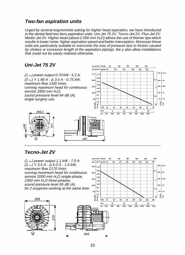
Two-fan aspiration units
Urged by several ergonomists asking for higher head aspiration, we have introducedin the dental field two-fans aspiration units: Uni-Jet 75 2V, Tecno-Jet 2V, Flux-Jet 2V,Medio-Jet 2V. Higher head (about 2.000 mm H2O) allows the use of thinner tips whichresults in lower noise, higher aspiration speed and better interception. Moreover theseunits are particularly suitable to overcome the loss of pressure due to friction causedby chokes or excessive length of the aspiration pipings; the y also allow installationsthat could not be easily realized otherwise.
Uni-Jet 75 2V
(1 ) power output 0.70 kW - 5.2 A,70 kW - 5,2(3 ) Y 1.95 A - ∆ 3.4 A - 0.75 kW,maximum flow 1330 l/min,running maximum head for continuousservice 2850 mm H2O,sound pressure level 64 dB (A),single surgery use.
Tecno-Jet 2V
(1 ) power output 1.1 kW - 7.5 A(3 ) Y 3.5 A - ∆ 6.0 A - 1.5 kW,maximum flow 2170 l/min,running maximum head for continuousservice 2000 mm H2O single-phase,2350 mm H2O three-phases,sound pressure level 65 dB (A),for 2 surgeries working at the same time.
11
psi
1,5
3
4,5
m b
ar
k p
a
75 7,5
15
22,5
30
37,5375
300
225
150
mm
H2O
mm
Hg
750
1500
2250
3000
3750
30
60
90
120
150
180
210
240
270
g.p.m.(U.K. liquid) 125 250 375 625
g.p.m.(U.S. liquid) 110
500
220 330 550 660 770
750
880440
m3/h 25 50 75 100 125 150 175 200
l/sec 12,5 25 37,5 50
l/m 375 750 1125 1500 1875 2625 3000 33752250
g.p.m.(U.K. liquid) 200 400 600 1000
g.p.m.(U.S. liquid) 175
800
350 525 875 1050 1225
1200
1400700
psi
1,5
3
4,5
m b
ar
k p
a
75 7,5
15
22,5
30
37,5375
300
225
150
m3/h 40 80 120 160 200 240 280 320
l/sec 20 40 60 80
l/m 600 1200 1800 2400 3000 4200 4800 54003600
mm
H2O
mm
Hg
750
1500
2250
3000
3750
30
60
90
120
150
180
210
240
270
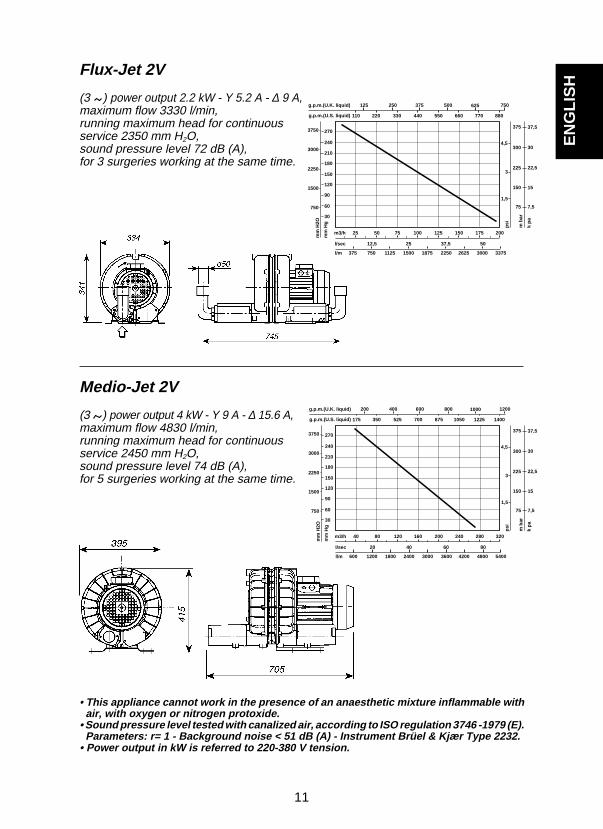
Medio-Jet 2V
(3 ) power output 4 kW - Y 9 A - ∆ 15.6 A,maximum flow 4830 l/min,running maximum head for continuousservice 2450 mm H2O,sound pressure level 74 dB (A),for 5 surgeries working at the same time.
Flux-Jet 2V
(3 ) power output 2.2 kW - Y 5.2 A - ∆ 9 A,maximum flow 3330 l/min,running maximum head for continuousservice 2350 mm H2O,sound pressure level 72 dB (A),for 3 surgeries working at the same time.
• This appliance cannot work in the presence of an anaesthetic mixture inflammable with air, with oxygen or nitrogen protoxide.• Sound pressure level tested with canalized air, according to ISO regulation 3746 -1979 (E). Parameters: r= 1 - Background noise < 51 dB (A) - Instrument Brüel & Kjær Type 2232.• Power output in kW is referred to 220-380 V tension.
EN
GL
ISH

12
Accessories for aspiration units (draw. 27 pag. 83)
For every aspiration unit is available a line of accessories including: vibration-proofdevices A, tube-holder sleeves, special tube B, low frequency silencer C fitted with non-return valve D, high frequency cylindrical silencer E and compensating valve F. If theunit is fitted with deadening box, the accessories are included there. On request it isavailable a certified bacteriological filter to filter the exhausted air.
Electrical control panels (draw. "A"-"B" pag. 81-82)
Every aspiration unit must be coupled to an electrical control panel with technicalfeatures suitable for the motor input assorbine and fitted with all the safeties requiredby safety regulations. Control panels, aspiration units and feeding lines must beprotected against electrical direct and idirect contact, from overload and overcurrent,in compliance with C.E.I. 64-8 regulations (E.C. corresponding regulations available onrequest) for first class appliances. Tables "A" and " B" show the indications for thechoice of the control panels in relation to the aspiration units. On request, control panellcan be equipped with: hour-counter, warning lights check, motor-off signal, tensioncontrol, manual/automatic running mode-switch.
PLANNING
Aspiration pipings (draw. A"-"B"- fig. 28 pag. 81-82-84)
The diameter of the aspiration pipings is related to several factors as the number ofthe surgeries that will work at the same time, the aspiration unit which has been chosenand the route of the pipings. Tables "A" and "B” show the different diameters in relationto various cases. Pipes must be of the best quality, of heavy type offering long lastingguarantee. Also the layout of the whole piping must facilitate the flowing of thefluids, avoiding as much as possible any loss of pressure due to friction. It isnecessary that every branching off and extension is made by 45° connections benttowards the surgeries, A; also 90° bends should be avoided as far as possible,they can be substituted by two 45° bends, B. In dry systems the aspiration pipingsdo not create any problem of levels or counterslopes, on the contrary in semi-drysystems, where aspirated liquids flows along the whole aspiration circuit, it isnecessary to avoid upward slopes and syphons. When the pipes are run in chasesthey must be inspectable; at the end of every branch it is always possible to insert aproper tool but when the pipings route does not allow a complete inspection from theseopenings, then some inspection holes should be placed at the most suitable points, C.It is advisable to check the tightness of the pipeline once it has been positioned:the test is useful in an dry system, essential in a semi-dry system. Once all outlets havebeen stopped up, pipings must be put under light pressure and checked with a suitableinstrument (manometer, mercury or water column): pressure should be steady.
Electrical wiring (draw. 28 pag. 84)
Aspiration units and control panels must be installed in a special technical room, purposelyprepared and fitted with all safety devices required by safety regulations and, if necessary,under authorization and surveillance of responsible authorities. Electrical feeding line willbe prepared according to tension and input shown on the control panels, on the aspiration

13
INSTALLATION
The dental unit is almost always fitted with the components needed for highvolume aspiration such as tip support, Mini-Separator and shutting valves. In casethese devices are not already fitted, the supplier of the aspiration system shallinstall these components inside the unit (with manufacturer’s authorisation) or inother suitable positions.5Tip support (draw. 30a pag. 85)
The tip support is generally fixed on the water unit, L. Dental ergonomics suggestalso different positions; they must be found together with the professional in orderto meet his own practice requirements in any working position.
Canisters and separators(draw. 6/15/29/30a/33a/33b/34a/34b pag. 13-85-87-88-89-90)
Only the more conventional installations, dry systems, posethe problem of canisters and Mini-Separators inside thesurgery. Semi-dry systems need no separator inside thedental unit.In semi-dry systems aspirated liquids flow along the wholeaspiration circuit and are drained in the engine-room: in largeinstallations a Separator-Tank, G draw. 29, collects all theaspirated debris from all the surgeries, separates air fromliquids and drains the latter in the waste. In small installationsthe same operation is carried out by a centrifugal system,separating air from water and draining the latter in the waste,draw. 33a-33b-34a-34b.In air ring systems, due to lack of room, the Canister (sepa-rator of blessed memory) has almost disappeared, to bereplaced by the automatic Mini-Separator, draw. 6. When thedental unit design does not offer any room, or anyway theassembling of the Mini-Separator is too difficult to assure aproper running, a good solution is Maxi-Canister plus box,draw. 15, placed at the bottom of the chair on the left (out ofthe dentist’s and the assistent’s operation range).Tip support and Separator must be installed so that liquidsare drained by gravity, in order to avoid stagnations of liquidsinside the pipings connecting the components when theaspiration is switched off; such liquids could be difficult to beaspirated rapidly on the restarting of the aspiration and couldcause some annoying standstills.The draining of the separator is worth particular attention: thedraining pipe must be able to drain 1.5 - 2 l/min.
units and on the electrical diagrams jointed to control panels; furthermore the feedingline must be fitted with an high-sensitivity differential switch. Starting from thecontrol panel a low tension three-cores cable of 1.5 mm2 (section increases withdistance) gets all the surgeries connected to the same plant, D. This line controlsthe switching on and off of the aspiration from each surgery in the system.
Draw. 6
Draw. 15
EN
GL
ISH
14
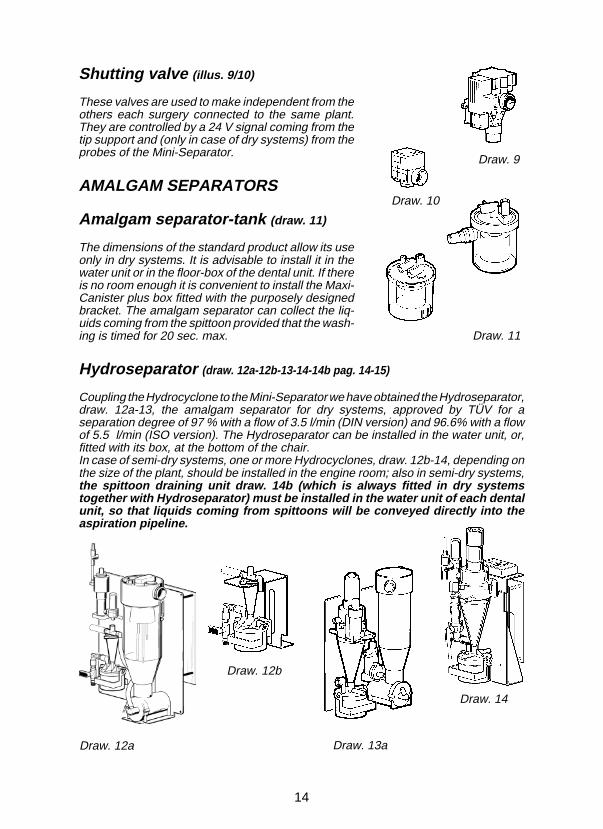
Shutting valve (illus. 9/10)
These valves are used to make independent from theothers each surgery connected to the same plant.They are controlled by a 24 V signal coming from thetip support and (only in case of dry systems) from theprobes of the Mini-Separator.
AMALGAM SEPARATORS
Amalgam separator-tank (draw. 11)
The dimensions of the standard product allow its useonly in dry systems. It is advisable to install it in thewater unit or in the floor-box of the dental unit. If thereis no room enough it is convenient to install the Maxi-Canister plus box fitted with the purposely designedbracket. The amalgam separator can collect the liq-uids coming from the spittoon provided that the wash-ing is timed for 20 sec. max.
Hydroseparator (draw. 12a-12b-13-14-14b pag. 14-15)
Coupling the Hydrocyclone to the Mini-Separator we have obtained the Hydroseparator,draw. 12a-13, the amalgam separator for dry systems, approved by TÜV for aseparation degree of 97 % with a flow of 3.5 l/min (DIN version) and 96.6% with a flowof 5.5 l/min (ISO version). The Hydroseparator can be installed in the water unit, or,fitted with its box, at the bottom of the chair.In case of semi-dry systems, one or more Hydrocyclones, draw. 12b-14, depending onthe size of the plant, should be installed in the engine room; also in semi-dry systems,the spittoon draining unit draw. 14b (which is always fitted in dry systemstogether with Hydroseparator) must be installed in the water unit of each dentalunit, so that liquids coming from spittoons will be conveyed directly into theaspiration pipeline.
Draw. 9
Draw. 14
Draw. 10
Draw. 11
Draw. 12a
Draw. 12b
Draw. 13a

15
Draw. 14b
EN
GL
ISH
Control panels and aspirationunits(draw. “A”-”B”-27-28-29-30a pag. 81-82-83-84-85)
Control panels, canisters, aspiration unitsand, as a rule, all appliances connected tothe power mains, especially when switchingon and off are automatic and take placewithout previous notice, must be installed inan engine room, where the entry is forbiddento patients and unauthorized persons. Forsmall plants fitted with aspiration units: Uni-Jet 75, Mini-Jet 2V, Uni-Jet 75 2V, Tecno-Jet,Tecno-Jet 2V and Flux-Jet, the engine roomcan be obtained in one of the surgery rooms,draw. 30a; a minimum deadening will beenough to reduce the noise to acceptablelevels.As for aspiration units Flux-Jet 2V, Medio-Jet, Medio-Jet 2V, Maxi-Jet 2S and otherwith higher flow, we recommend their instal-lation at a longer distance from the surgery,draw. 29. Every engine room will be fitted
with: an electrical feeding line proportionate to the power installed, with a switchand an high sensitivity differential; an outlet to exhaust outside the aspirated airand to ventilate properly the room (min. temp. +5 °C - max. temp. +30 °C).Air exhausted from the aspiration units is always very damp and its temperature ishigher than the room one; due to rarefaction, some condensation, which must bedischarged, can form in the draining pipe.The manufacturer offers a certain number of accessories like: brackets, deadeningboxes, low frequency silencers, draw. 27-C, high frequency silencers E, vibration-proofdevices A, hoses B and heat-resistant pipes H. These accessories are not alwaysindispensable, but they are often useful to prevent inconveniences and troubles. Tables"A" and "B", pag. 81-82, give some information useful for the choice of the aspirationunits and of the control panels according to the number of surgeries supposed to beworking simultaneously.Assembling of two or more aspiration units in parallel lowers absorbtion costswhen the plant is not in full use and reduces the risk of total failure. In systems madeup of two or more machines in parallel, operation controls and luminous/acousticsignals are useful both in the technological room and in the secretary’s office; otherwisea progressive stop of the system might occur. It is thus advisable to request the controlsand signals listed below.Useful controls and signals: operation hour-counter, luminous switches with ma-chine operation modes (manual and automatic), luminous signal test push-button,phase-on tester.Luminous and acoustic signals for failures: suction assembly, drainage pump, fulltank, mix separator maximum level.The reader is kindly requested to note that even if the sound pressure levels data(reported at the units illustrations) have been gathered systematically and precisely,they can be anyhow influenced by environment, by machines position and by othersfactors; consequently eventual discrepancies should be considered as resulting fromthese situations or from data gathering methods.

16
OPERATION AND USE
Knowing how the plant operates will make the surgery staffself-sufficient and self-confident.
Dry and semi-dry systems(draw. 29-30a-31-33a-33b-34a pag. 85-86-87-88-89)
Once the main switch on the feeding line and the control panel one are turned on (I =on / 0 = off), lifting up a terminal A, draw. 30a, from its seat will start the aspiration: themicroswitch of the tip support, with a 24 V closing signal, controls the opening of theshutting valve C and starts up the aspiration unit D. Through the operative tip E and thelifted hose liquids and air, called in by the negative pressure, flow into the manifold B,where they are submitted to a first filtration. In a dry plant, after passing through themanifold, liquids get to the Mini-Separator F, where they are drained. In dry systemsonly air flows after the Mini-Separator, whilst in semi-dry systems fluids get to theSeparator Tank G draw. 29 (or the centrifuge B, draw. 33a-33b-34a in small semi-drysystems) in the engine room where they are drained too. In both types of system airgets to the aspiration units and is exhausted outside, H draw. 29.If a signal from the Mini-Separator indicates that the maximum level has been reached,the shutting valve of the involved surgery will close. In semi-dry systems, the Separator-Tank is fitted with the overflow device that might be activated during washingoperations. The eventual presence of an amalgam separator fitted together with theMini-Separator (Hydroseparator) in the dental unit water-unit (dry systems) or installedin the engine room for semi-dry systems (Hydrocyclone) does not affect or modify theoperation of the plants. The reader can find a more complete and exhaustive descriptionof the Hydroseparator operation on the specific manual.
MAINTENANCE
This section of the instruction manual, that we would like tobe known also by dental engineers, is particularly meant forthe surgery staff (draw. 14b-16-17-18-19-29-30a-31 pag. 15-17-85-86)
Before every cleaning or maintenance operation on the aspiration plant, weardisposable gloves, mask, goggles and overall, carry out a careful sanitizing washingwith Puli-Jet and water, draw. 19, if necessary repeat the operation several times; theaim is to obtain a good cleaning of the internal components, particularly of the partsinvolved in the maintenance operation and to abate as far as possible the bacterial level.Before starting maintenance operations on moving or under tension parts, cut offpower. To clean and sanitize internally the aspiration plant act as follows, draw. 19:prepare the Puli-Jet solution following the direction printed on the bottle label; insert thetip no 17 in the large terminal by means of the adapter no 16; insert the tip no 10 in thesmall terminal; dip one tip at a time into the solution; aspirate it without letting any airenter into the plant; after some seconds lift rapidly the tip upwards and aspirate air only.Repeat this procedure some times; it will create the turbulence needed to clean all pipesand components that get in touch with the aspirated liquids. Puli-Jet dissolves mucusand blood, its special detergent action enchances the antimicrobial factor obtaining asanitizing and deodorizing effect. If it is used systematically and regularly, Puli-Jetassures a good functioning of the plant, prevents foam build-up and formation

17
Draw. 18 Draw. 19Draw. 17Draw. 16
of bacterial coatings draw. 31, responsible for sudden stops and for progressivereduction of the aspiration power. During the work solid particles are aspirated togetherwith liquids: they must be trapped by filters; no aspiration plant can run properly and fora long time without a suitable filtering of the aspirated debris. In time large debris impairthe running of the draining valves and of diaphragms closing and opening the aspirationpipes. Lacking the filter on the tip support, draw. 16, a self-contained filter, draw. 17,must be placed between the tip support and the Mini-Separator, draw. 30a det. I. In asemi-dry system the self-contained filter, draw. 17 must be placed between the tipsupport and the Electropneumatic valve C, draw. 29 det. I. The amalgam separators(Hydroseparator or Hydrocyclone) which can receive the liquids drained by thespittoon, draw. 14b, are already fitted with filter, draw. 18.
Ordinary maintenance operations(draw. 17-19-20-21-22-32 pag. 17-18-86)
First of all, as described in the previous paragraph, before starting any maintenanceoperations wear disposable gloves, mask, goggles and overall and clean-sanitize theplant with Puli-Jet, draw. 19. Use of detergents and disinfectants too strong or somewaynon-compatible with materials (metal, rubber and plastic) of the aspirator is strongly advisedagainst. The Manufacturer disclaims all responsibility and will not consider under guaranteeany appliance or plant treated with unsuitable products, even if such products are describedas specially made for surgical aspirators. Secondly, filters are to be replaced; beforereaching for the tip support filters, switch on the aspiration for some seconds,aspirating air only: it will prevent any liquid spill.While aspiration is still on, take off plugs (draw. 16-20) and replace the filters; the recoveredfilters are surely contaminating and before being reused, they must be kept immersed in ahigh concentration sanitizing or disinfecting solution for 6/8 hours. Any amalgam trappedin the filter shall be recovered and put into the disposable amalgam container of theamalgam separator, following the directions jointed to the separator itself. External hosesand tip supports can be cleaned and sanitized draw. 32. Terminals (that can be detachedfrom hoses by twisting and pulling them, draw. 21) and tips are instruments-washerproof and autoclavable. Repeated sterilizations speed up, of course, the ageingprocess, but the handiness of replacement and price have been studied and calculated forfrequent sterilizations.Also replacement of external hoses, subject to ageing due to the liquids flow, has beenstudied to be easy and handy, draw. 22; before detaching the external hoses frommanifold, switch on the aspiration without aspirating liquids, lift upwards the looseend of the hose to ease the aspiration of the liquid left inside and to prevent any spill.
EN
GL
ISH

18
Draw. 21 Draw. 22
Draw. 16
Draw. 20
Draw. 23 Draw. 24
Main ordinary maintenance operations(draw. 16-18-19-20-21-22-23-24-25-26-30a-32 pag. 17-18-19-85-86)
• After each surgical or long lasting operation: aspirate water, preferably warm, clean theexternal hoses of the tip supports, replace the terminals, draw. 21-32.• After every working day: clean the plant with hot (50 °C) water and Puli-Jet, cleanthe filters and replace the sanitizing antifoaming tablets, clean the tip supports andthe external hoses, clean and sterilize terminals and tips, draw. 16-18-19-20-23-24.
Antifoaming tablets (draw. 23-24 pag. 18)
We strongly recommend the use of antifoaming agent particularly in case of surgicaloperations. Blood, on contact with air and with turbulence created by aspiration, builds-up a large quantity of foam, which activates the emergency device of the appliancestopping the aspiration. Many other substances cause foam builds-up, such as mucusand some disinfectants used to wash and treat the mouth; so the use of the antifoamingtablets (which have no contraindications) is always advisable.The present production of antifoaming agent adds to its primary antifoaming effect alsoa bacteriostatic and sanitizing action which anyway does not substitute the detergentand disinfectant action of Puli-Jet but on the contrary supports it during the day, whencleaning operations cannot be easily carried out. Sanitizing antifoaming tablets must beput into the tip support filter and placed so that aspirated liquids, through the filter, carryaway some particles of the product. If the tablets are placed in the filter, draw. 23-24, inthe evening after the cleaning with Puli-Jet, on the morrow they will be softened and theireffect will be immediate; tablets placed in the filter just before starting the day’s work willbe too dry and will need some minutes before being activated.

19
Main extraordinary maintenance operations reserved to den-tal engineers
Every six months: check the draining valves, syphons and drainages, overflow probes,relays, electrovalves, amalgam separator (impeller motor and draining pump); testappliances for noise and vibration, sure clues of the state of the components involvedand of the installation.
The manufacturer, distributors, agents and service engineers are willing to providesuggestions, instructions, and to supply spare parts, literature, and any other usefulinformation.
Important notice
The appliances are guaranteed for one year from date of sale, provided that guaranteecard addressed to the manufacturer is returned to the manufacturer reporting date ofsale, retailer's stamp and customer's name.
Guarantee and manufacturer liability cease in case the appliances are treated withunsuitable products or products not suggested by the manufacturer or in case they areused unproperly or found tampered by any kind of action performed by unauthorisedpeople.
Technical needs, updating, functional and legislative problems, inability to locateproducts or semi-finished products can lead the manufacturer to modify the applianceswithout notice.
Draw. 22 Draw. 25 Draw. 26
• Every fifteen days: check the draining valves and the probes (in case of problems callfor the authorized engineer), lubricate the external hoses and the terminals slides withLubri-Jet, wiping the excess off, draw. 22-25-26.• Every six months: replace external hoses, terminals and tips, draw. 30.• Before leaving the surgery for several days: start the aspiration system, have it runningfor 5/10 minutes with stopped up terminals and without aspirating liquids; the aspirationunit will dry completely: this can prevent the formation of salts, typical of light alloys andproduced by moist and basic substances, which sometimes can jam the fan and blockthe motor.
EN
GL
ISH

20
Transport and storage
For transport and storage, packed equipment can be exposed to a-10 °C / +60 °C temperature range.
Packages cannot be exposed to water and splashing and cannot tolerate humiditygreater than 70%.
Packages with the same weight can be stored in piles of three only.
Transport of second-hand appliances
Prior to packing, clean and sanitize with Puli-Jet (see “Cleaning and Maintenance”section).
Place unit into a polythylene bag, seal and pack in 3-layer corrugates board.
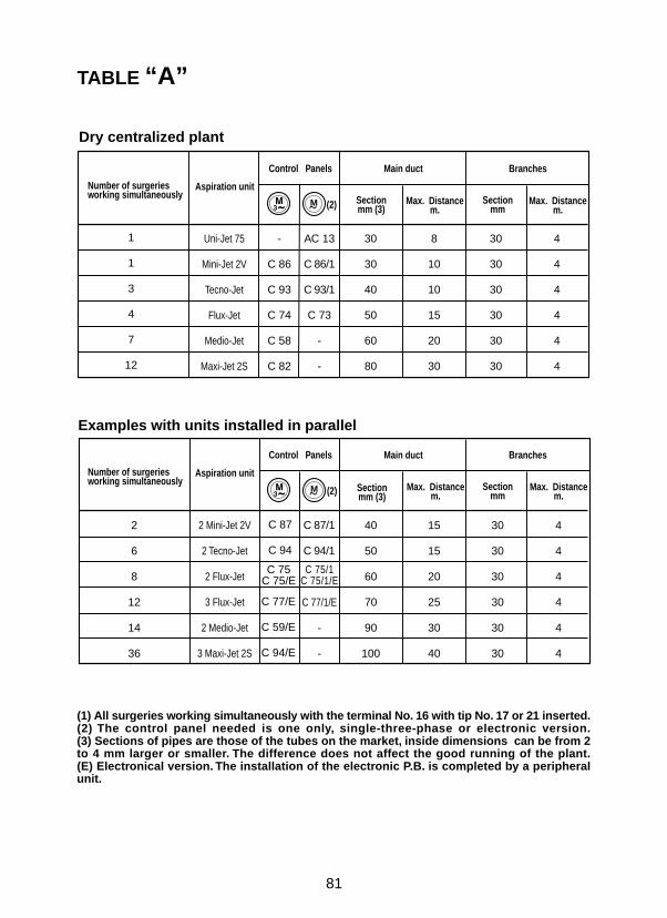
TABLE “A”
Dry centralized plant
(1) All surgeries working simultaneously with the terminal No. 16 with tip No. 17 or 21 inserted.(2) The control panel needed is one only, single-three-phase or electronic version.(3) Sections of pipes are those of the tubes on the market, inside dimensions can be from 2to 4 mm larger or smaller. The difference does not affect the good running of the plant.(E) Electronical version. The installation of the electronic P.B. is completed by a peripheralunit.
81
1
1
3
4
7
12
Uni-Jet 75
Mini-Jet 2V
Tecno-Jet
Flux-Jet
Medio-Jet
Maxi-Jet 2S
30
30
40
50
60
80
8
10
10
15
20
30
30
30
30
30
30
30
4
4
4
4
4
4
AC 13
C 86/1
C 93/1
C 73
-
-
-
C 86
C 93
C 74
C 58
C 82
(2)M~
Number of surgeriesworking simultaneously
Aspiration unit
Control Panels Main duct Branches
Sectionmm (3)
Sectionmm
Max. Distancem.
Examples with units installed in parallel
2
6
8
12
14
36
2 Mini-Jet 2V
2 Tecno-Jet
2 Flux-Jet
3 Flux-Jet
2 Medio-Jet
3 Maxi-Jet 2S
40
50
60
70
90
100
15
15
20
25
30
40
30
30
30
30
30
30
4
4
4
4
4
4
C 87
C 94
C 77/E
C 59/E
C 94/E
C 75C 75/E
C 75/1C 75/1/E
C 87/1
C 94/1
C 77/1/E
-
-
(2)M~
Number of surgeriesworking simultaneously
Aspiration unit
Control Panels Main duct Branches
Sectionmm
Max. Distancem.
Sectionmm (3)
Max. Distancem.
Max. Distancem.

TABLE “B”
82
1
2
3
5
Uni-Jet 75 2V
Tecno-Jet 2V
Flux-Jet 2V
Medio-Jet 2V
30
40
50
60
15
20
25
30
30
30
30
30
6
6
6
6
(2)M~
-
C 74
C 58
C 82
0035
C 73
-
-
Number of surgeriesworking simultaneously
Aspiration unit
Control Panels Main duct Branches
Sectionmm (3)
Max. Distancem.
Sectionmm
3
6
9
10
30
2 Tecno-Jet 2V
2 Flux-Jet 2V
3 Flux-Jet 2V
2 Medio-Jet 2V
3 Maxi-Jet 2S
40
60
70
70
100
20
30
35
40
40
30
30
30
30
30
6
6
6
6
6
(2)M~
C 75
C 59/E
C 60/E
C 83/E
C 84/E
C 75/1
-
-
-
-
Number of surgeriesworking simultaneously
Aspiration unit
Control Panels Main duct Branches
Sectionmm (3)
Max. Dist.m
Sectionmm
Max. Dist.m
Dry centralized plant
Examples with units coupled in parallel
(1) All surgeries working simultaneously with the terminal No. 16 with tip No. 17 or 21 inserted.(2) The control panel needed is one only, single-three-phase or electronic version.(3) Sections of pipes are those of the tubes on the market, inside dimensions can be from 2to 4 mm larger or smaller. The difference does not affect the good running of the plant.(E) Electronical version. The installation of the electronic P.B. is completed by a peripheralunit.
Max. Distancem.

83
Installation layouts
Draw. 27
C
DB
B
F
A
H
E

Layout of 2 Flux-Jet units with 9 surgeries
Draw. 28
84
D
C
C B
45°
A
45°
45°

85
Layout of semi-dry centralized plant
Draw. 29
Layout of dry centralized plant
Draw. 30a
EA
B
C I G
C
H
EA
B
C IF
C
D
L
F
H

Bacterial coating
Draw. 31
Draw. 32
Terminals and Tip supports cleaning
86
Blok-Jet (exemplary)
Draw. 30c
Draw. 30b

87
TURBO-JET 1 modular WITH SOUND-PROOF BOX
TURBO-JET 1 modular
TURBO-JET 1 modular WITHOUT BOX
00
200
400
600
800
1000
1200
1400
1600
mm
H2O
m3/h10 20 30 40 50
60 Hz50 Hz
540
355
220
490
570
409
73 55
18166 67
326
369
Draw. 33a
TURBO-JET 1 modular
B
WASTE FILTER
WASTE INLET Ø30 WASTE
OUTLET Ø25
AIR FILTER
WASTE INLET Ø30 WASTE OUTLET Ø25
EXHAUSTEDAIR OUTLET Ø30

88
TURBO-JET 2 modular WITH SOUND-PROOF BOX
TURBO-JET 2 modular
TURBO-JET 2 modular WITHOUT BOX
00
500
1000
1500
2000
2500
3000
mm
H2O
m3/h
10 20 30 40 60
60 Hz50 Hz
50
540
220
355
453322 422
131140 44
58,5
497
40
58,5
Draw. 33b
TURBO-JET 2 modular
B
WASTE INLET WASTE OUTLET
EXHAUSTEDAIR OUTLET
WASTEINLET
WASTE OUTLET
EXHAUSTEDAIR OUTLET

89
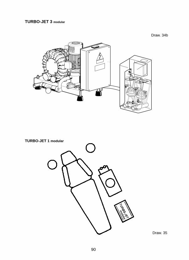
TURBO-JET 3 modular
TURBO-JET 3 modular WITH SOUND-PROOF BOX
TURBO-JET 3 modular WITHOUT BOX
mm
H2O 500
m3/h
1000
1500
2000
2500
3000
00 20 30 50 80 100
60 Hz50 Hz
40 60 90
Draw. 34a
650
300
550
150
490
100
552
520
585
74
583
114,540
507
BWASTEINLET
WASTE OUTLET
EXHAUSTEDAIR OUTLET
EXHAUSTEDAIR OUTLET
WASTEOUTLET
WASTEINLET
90
TURBO-JET 1 modular
Draw. 35
VW
AR
TIC
OL
O N
°
CA
TTA
NI S
.p.A
. Parm
a
TURBO-JET 3
CATTANI SpA Parma Italy
modular
TURBO-JET 3 modular
Draw. 34b

91
Draw. 36
B
C
ø 40
ø 30
Cø 30
E
DCC
A
C
D
A
A
C
DTURBO-JET 3 modular
TURBO-JET 2 modular
ø 3
0
ø 40ø 40
ø 30
ø 40
ø 30
ø 40
E
ø 3
0

ITALIAN PATENTS OR PATENT APPLICATIONS:1201707 - 1234267 - 1234828 - 1259318 - 1.187.187 - 1253460 - 0766008 - 1236271 - 01242921
FOREIGN PATENTS OR PATENT APPLICATIONS:EP 0040181 - AU 546.143 - US 4,386,910 - EP 0 638 295 - EP 0 254 687 - AU 590433 - US 4,787,846 - US 5,039,405- EP 0335061 - US 5,002,486 - EP 0211808 - AU 580839 - US 4,684,345 - EP 0 557 251 - US 5,330,641 - EP 0766008- US 4,710,209
PENDING PATENTIT M093U000019 - EP 0 749 728 - IT M095U000030 - JP 168553/97 - IT M097A000139 - IT M098A000019 - IT M098A000119
Ed.
MA
G. 9
9
Via G. Natta, 4/A - 43100 Parma (Italy) - Tel. +39 0521 607613 - Telefax +39 0521 607628-607855http://www.esam.it Email: [email protected] con Sistema Qualità Certificato secondo UNI EN ISO 9002
S.p.A.
Via G. Natta, 6/A - 43100 Parma (Italy) - Tel. +39 0521 607604 - Telefax +39 0521 607628-607855http://www.cattani.it Email: [email protected] con Sistema Qualità Certificato secondo UNI EN ISO 9001 - UNI CEI EN 46001
CATTANI S.p.A.