dry screw compressors in process gas …
TRANSCRIPT

DRY SCREW COMPRESSORS IN PROCESS GAS APPLICATIONS INCLUDING MAINTENANCE CONSIDERATIONS
by Glen B. Nordquist
Product Manager, Oil Free Screw Compressors
A-C Compressor Corporation
Appleton, Wisconsin
Peter A. Bielskus Staff Engineer
Amoco Oil Company
Chicago, Illinois
and Russ Clayton
Manager of Customer Support
A-C Compressor Corporation
LaPorte, Texas
Glen B. Nordquist is Product Manager, Oil Free Screw Compressors, for A -C Compressor Corporation, Appleton, Wisconsin. He holds a B.S. degree in Mechanical Engineeringfrom lowa State University. During his more than 40 years of compressor experience, he initially was instrumental in the technical introduction of screw compressors into the United States and has held various managerial positions in engineering, sales, marketing, and service as related
to oil free screw compressors. He served as a member of the task force in writing API619, Rotary-Type Positive Displacement Compressors for General Refinery Services.
Peter A. Bielskus is a Staff Engineer with Amoco Oil Company, in Chicago, Illinois. He holds a B.S. degree in Mechanical Engineeringfromlllinois Institute ofT echnology. His responsibilities include the initial specification, selection, field installation , and consultation for rotating equipment. He has over 20 years of experience working with rotating equipment including design, installation and maintenance.
Russ Clayton is Manager of Customer Support for A-C Compressor Corporation. He is responsible for the corporation's after market services including field service engineering, repairs , replacement parts, and engineered revamps. He started with the Allis Chalmers Field Service Group (1979) as a service representative. Since that time, he has held various positions within the company including Field Service Specialist, Sales Engineer and Shop Manager for the
3
Los Angeles Repair Center. Mr. Clayton is a 1975 graduate ofTexas A&M University.
ABSTRACT
The dry screw compressor, which combines the advantages of positive displacement with rotary motion, is gaining wider international acceptance for process gas applications.
The selection of dry screw compressors is dependent upon proper evaluation of the thermodynamic and mechanical characteristics inherent with this type of compressor. To be discussed are the selection parameters, capabilities, and limitations that must be considered for any process gas compressor application.
The selection parameters include, but are not limited to, the following :
• Application range: Flows, pressures and temperatures suited for screw compressors as compared to other types of compressors.
• Gas handled: Molecular weight variations, corrosive elements, erosive components, entrained liquids, polymer formation, and other gas characteristics that can best be handled by dry screw compressors.
• Process control of flows, pressures and temperatures.
• Compliance with recognized design standards, i .e., API, PNEUROP.
• Construction features and design parameters that make dry screw compressors suitable for a w ide range of applications. This section discusses bearing loading, shaft bending stresses, torsional and lateral v ibration analysis , and other mechanical design criteria.
The maintenance section of this presentation is intended to offer a broad overview of this equipment and its unique characteristics and special requirements. Particular emphasis will be placed on the restoration of aero performance, which may over extended periods of time deteriorate due to rotor and casing clearance degradation.
Topics include predictive and preventative maintenance practices and guidelines, which can extend the useful life of the
CORE Metadata, citation and similar papers at core.ac.uk
Provided by Texas A&M University

4 PROCEEDINGS OF THE TWENTY-FIRST TURBOMACHINERY SYMPOSIUM
equipment and minimize unexpected outages, field overhaul techniques, repair shop procedures and rotor and case repairs including welding, coatings, seal stripping, and metal locking.
INTRODUCTION
Screw compressors, which were first introduced over 40 years ago, have gained ever increasing acceptance as the compressor of choice for a wide variety of compression services in the chemical, petrochemical, refining, and gas processing industries.
The screw compressor combines the advantages of positive displacement (like a reciprocating compressor) with rotary motion (like a centrifugal compressor) so as to provide a wide range of operating capabilities.
Screw compressors gained a major impetus upon the development and first publication in 1 975 of "API Standard 6 1 9, RotaryType Positive Displacement Compressors for General Refinery Services."
Quoting from and giving credit to, the following is noted: "Screw compressors find use in many chemical services. Most
significantly, they are employed where no other compressor will work or is economic. They tolerate more abuse than any other comparable unit. On low molecular weight, they enj oy the same benefit as reciprocating compressors since the significance of low density is not detrimental as in the case with centrifugal compressors" [1].
"Put the Screws to Your Compressor Applications. The often overlooked helical-screw compressor can offer CPI plants a number of benefits" [2].
The main subjects to be covered herein were written individu-ally and are divided into the following sections :
• Compressor Selection Parameters
• An Overview by an End User
• Maintenance, Overhaul and Repair Techniques for Oil Free Screw Compressors
COMPRESSOR SELECTION PARAMETERS
The proper selection of any type of compressor for process gas applications is dependent upon the complete evaluation of many separate, but yet interdependent, operating and design variables. The following is a suggested step-by-step procedure to assist the user in selecting the specific type of compressor to meet his/her needs. In many cases more than one type of compressor should be considered. Specifically, the steps sequenced in the following will, in the end result, demonstrate when, where, how, and why the oil free screw compressor can best be applied.
Flowrate and Pressure Range Parameters
A diagram shown in Figure 1 is of available compressors based on thermodynamic principles of compression (dynamic and positive displacement) and i s categorized into the types of compressor employing each principle. Also tabulated are the typical flow ranges and pressure capabilities of each compressor type.
To facilitate the user's review and evaluation, the diagram may be restructured into a composite performance map (Figure 2) which shows the typical application ranges (flow vs discharge pressure) for the various compressor types.
Analysis of the performance map points out the following as relates to flow :
• Ultra-high flows, those above approximately 540,000 cfm, mandate the use of dynamic type axial flow compressors.
• High flows, above 35,000 and up to 540,000 cfm, fall within the flow range of centrifugal compressors.
SELECTION
!!.!
COMPRESSOR TYPE
SELECTION BASED ON FLOW AND PRESSURE CAPABILITIES
Approximate Operating Ranges
Cortpreasor Type Flow CCFM) Pressure CPSIG)
Axial Flow 20,000 - 2.000.000 10- 100
Centrifugal 1.200 - 540,000 VAC - 10,000
Reciprocating 100 - 10.000 30- so.ooo
Rotary
S1iding Vane so- 6,000 VAC - 1SO
Straight Lobe Blower soo - 40.000 VAC - 15
Liquid Ring 200- 6.000 VAC - 30
*Screw 2SO - 35,000 VAC- 580
*The oot1nun selection for )lOUr 1ntel"ftted1ate ranae flows and oreaaures.
Figure 1. D iagram of Compressor Types.
JO"
(!) Ui a. Jo•
l!! ::l tn
Jo• tn l!! a. UJ (!) a: <( :t u tn � 0
10
I I ' ' • I I I I I
---------�---------�--------�---------�---------�--· I I I I I 1 I I I I I 1 I I I I I I I I I 1 I I I I 1 I I I I I ��,.,.,., I I I 1 I I I
I I I I --�--------�---------�--·
I I I I I I I I I I • I : 580 PS:.IG WAX :
I I I I
------ J_ ----·---�--· I I I I
Js0oo CF'M MAX : I I I I I "...,.""""".,......,.....,....,...,.....,....., _____ i __ .
INLET FLOW - ACFM
I I I I I I I I
Figure 2. Performance Map.
• The intermediate flow range of approximately 250 up to 35,000 cfm can be handled, in whole or in part, by a wide variety of compressor types, i.e., centrifugal, reciprocating, oil free screw, and other rotary types.
• Low flows, below 250 cfm, fall almost exclusively into the reciprocating compressor range.
To the flow ranges, the parameters imposed by discharge pressure must now be added. Pressure limitations are primarily established by the hoop strength of the materials used in the pressure containment vessel, i.e., cylinder or casing. Secondarily; sealing limitations, bearing loading, shaft bending stresses and other mechanical limitations are imposed.

DRY SCREW COMPRESSORS IN PROCESS GAS APPLICATIONS INCLUDING MAINTENANCE CONSIDERATIONS 5
Again, upon additional analysis of the performance map, the application ranges of the various compressor types may be further narrowed.
• Reciprocating compressors are capable of attaining the highest discharge pressure and have a limitation of approximately 50,000 psig. However, at such hyperpressure the flow range is decidedly narrow.
• Centrifugal compressors, barrel type, are capable of operating at up to the very maximum of 1 0,000 psig, but the nominal limit most often used is approximately 5,000 to 6,000 psig.
• Oil free screw compressors are limited to the intermediate maximum range of 400 to 580 psia depending upon the manufacturer.
• Below 1 5 0 psig, the user has an almost unli mited variety of compressors from which to make a selection.
To summarize, based on the preceding, the oil free screw compressor finds its application niche in the intermediate flow and pressure ranges. To be repetitious, they are as follows:
Flow: 250 to 35,000 CFM Pressure: Vacuum, 1 .5 psia to 580 psia
Having established the flow and pressure limitations, consideration must now be given to the other selection parameters.
PROCESS GAS AND PROCESS VARIABLES
Oil free screw compressor manufacturers are often and erroneously told to believe that process gases are clean, dry, noncorrosive and nonpolymer forming. This is a fallacy. However, and to repeat a quoted statement given in the introduction; "Most significantly they (screw compressors) are employed where no other compressor will work or is economic. They tolerate more abuse than any other comparable unit."
Now evaluate how the screw compressor, which combines the advantages of a reciprocating compressor (positive displacement) with those of a centrifugal compressor (rotary motion), serves to provide the utmost compression capability and reliability even under the extremes imposed by a majority of process gases and process conditions.
ADVANTAGES OF OIL FREE SCREW COMPRESSORS
Low Molecular Weight Gases
• Optimum adiabatic efficiencies are obtained. For example, the following tabulation applies to three typical rotor diameter compressors, operating on hydrogen (MW = 2.0), compression ratio 1 .7 and a rotor tip speed of 450 ft/sec.
Rotor Diameter <Inches) Flow Ccfm) Adia. Eff. %) 1 0.5 1 3.25
1 6.5
3000 5000
7 900
52.7 56.7
60. 1
A piston type compressor, which is the most efficient compressor type available, will have an estimated adiabatic efficiency range of 65 to 75 percent for s imilar operating conditions.
Medium tip speeds of 300 to 450 ft/sec vs centrifugal at 900 ft/ sec and up through Mach 1 .
• S ingle stage case vs multistage centrifugal with multiwheels and/or multicasings.
Molecular Weight Variations
• No "surge" nor significant dropoff in head (discharge pressure) or flow, such as might be exhibited by a centrifugal compressor.
Process Pressure and Temperature Variations
• Positive displacement feature permits wide variations with minimal change in flow. Driver power requirements would, however, increase with increased inlet pressure.
Entrained Liquids and Particulate Matter in Process Gas
• Liquid slugs are not a problem; in fact, many process screw compressors are liquid injected.
For a reciprocating compressor, the valves would be subject to "wire drawing" eros ion. Further, cylinder lubrication would be washed away causing adverse piston ring and cylinder bore wear. Excess liquid at the top dead center of the piston could cause the cylinder head to fracture.
• For centrifugal compressors, with high rotative speeds (tip speeds in excess of 900 to 1 200 ft/sec), the liquid impingement velocity on the wheel would promote erosion. Large slugs of liquid can destroy a high speed centrifugal wheel.
• Particulate matter in the process gas promotes the same phenomenon as liquid entrainment except that abrasion is also introduced.
Polymer or Tar Forming Gases
The oil free screw exhibits a number of advantages in such services.
• Polymer or tar buildup on the rotors reduces rotor-to-rotor clearance, thus making the screw compressor more efficient. Excess buildup is inhibited in that the intermeshing and rollingsliding motion between the rotors wipes off and limits the buildup (Figure 3) .
Figure 3. Symmetrical Rotor Profile.
• There are no piston rings or valves to foul such as in a reciprocating compressor.
• As compared to a centrifugal compressor, there are no high speed impellers and no diffusers or scrolls to foul or plug.
• The screw compressors are less subject to polymer buildup unbalance than a centrifugal compressor because of the substantially lesser speeds. Further, the screw compressor rotor weight -tospeed ratio is high compared to a centrifugal, which has a comparatively low weight-to-speed ratio. Therefore, the screw compressor is far less sensitive to unbalance.
• In general, polymer and tar formation accelerates as compressor discharge temperature increases. In many applications, liquid

6 PROCEEDINGS OF THE TWENTY-FIRST TURBOMACHINERY SYMPOSIUM
injection (water, ODCB, and other process compatible liquids including naptha) have been used. The latent heat of vaporization of the liquid as it flashes to vapor absorbs the heat of compression of the compressor. Excess liquid is normally injected to further cool the gas (sensible heat) and act as a flushing agent.
The amount of liquid inj ected is minimal; normally within the range of 0 .5 to 2 .5 gallons per minute. Injection rate is mainly dependent upon the variables: flowrate and degree of saturation of the gas, gas horsepower and specific heat (Cp) of the injected liquid.
Some typical polymer and tar forming gases handled by screw compressors utilizing liquid inj ection are acetylene, butadiene, styrene off-gas and coke oven gas . A typical turbine driven styrene off-gas compressor is shown in Figure 4. A typical butadiene compressor with motor drive is as shown in Figure 5 .
Figure 4. Turbine Driven Styrene Of/Gas Compressor.
Figure 5. Butadiene Compressor with Motor/Gear Drive.
Corrosive Gases
No type of compressor is immune to corrosion. Therefore, compressor manufacturers have made available various types of corrosion resistant materials such as, and in order of their effectiveness: a variety of stainless steels, corrosion resistant weld overlays, platings, and coatings .
It i s well known that stainless steels resist corrosion because they are "passive," i .e . , have a protective layer or film, generally an oxide, on the surface of the metal.
Factors which impact on the rate of corrosion are as follows:
• Concentration and type of corrosive elements in the gas stream. In this case, the proper material selection is key .
• Surface finish. The smoother the finish the lesser the rate of corrosion. The screw compressor has an advantage in that all surfaces are fully exposed and may be finished to approximately 64 microinches or better; whereas, in a centrifugal compressor wheel of the closed type, the internal surfaces are not exposed and comparable surface finish may be difficult to achieve .
Further, the susceptibility to erosion, subsequent surface roughness and, therefore, higher corrosion rates are much greater for a centrifugal compressor which turns at tip speeds of two to four times that of an oil free screw compressor.
Operating Stresses
Stress-corrosion cracking is a form of corrosive attack and is a result of high tensile stresses in the material. Oil free screw compressor rotors have no structural welds exposed to the process gas . Centrifugal compressor wheels in the majority do have the blades welded to the hub and a cover welded to the blades . The centrifugal wheels are stress relieved to eliminate any locked-in fabrication stresses.
Screw compressor rotors are, as a general standard, made from necked down forgings which are stress relieved prior to machining the rotor lobes . After rough machining the rotor lobes, they are again stress relieved to remove any machining stresses.
The operating tensile stresses due to centrifugal forces are much higher in a centrifugal wheel than in a screw compressor rotor because of the substantially high rotative speeds and tip speeds . Therefore, the centrifugal wheel will be more prone to the phenomena of stress-corrosion cracking as compared to a screw compressor rotor.
Other Considerations
It is recommended that the user refer to the N ational Association of Corrosion Engineers (NACE) Standard MR-0 1 -75 for material limitations and recommendations for sour environments, i .e . , gases containing water as a liquid and hydrogen sulphide. The combination of the two may cause sulfide stress cracking (SSC) of certain materials .
If the gas handled is at a pressure of less than 65 psia and the partial pressure of the hydrogen sulphide in the gas is less than 0.05 psia, NACE is not considered applicable and carbon steel materials having a yield strength of less than 90,000 psi and a hardness of 22 Rockwell C may be utilized.
Also, the user may consider bypassing hot gas from discharge back to suction, thereby raising the inlet temperature so that the water in the gas is above the dew point and no longer a liquid.
Although not commonly used, it i s possible to inj ect amines, filming or neutralizing, into the compressor, so as to mitigate the adverse effects of the corrosive gases being handled.
PROCESS CONTROL AND COMPATIBILITY WITH NEW OR EXISTING PROCESS SYSTEMS
Startup Flexibility
Often overlooked are the variables related to initial startup. The screw compressor, due to its relative insensitivity to changes in molecular weights, may be run on air to blow out piping. The piping system can then be flanged up and the unit ran on nitrogen to purge the system. Lastly, process gas is introduced and the compressor put onstream for continuous operation.
• It i s to be noted when the process gas has a wide variation in molecular weight from that of air or nitrogen, that a centrifugal

DRY SCREW COMPRESSORS IN PROCESS GAS APPLICATIONS INCLUDING MAINTENANCE CONSIDERATIONS 7
compressor can require a highly sophisticated startup control system, or in some cases, even a variable frequency drive may be required.
Compatibility with Existing Systems
The screw compressor may be operated in parallel with existing centrifugal or reciprocating compressors. It may also be operated in series as a booster compressor to supercharge a high pressure reciprocating compressor or it may operate as a second stage with feed from a high volume centrifugal compressor.
Certain processes, such as styrene off gas, do require occasional regeneration of catalyst at elevated pressures. It is possible to use two compressors operating in parallel on process gas at relatively low pressures and appropriately valve the process piping system so that the compressors may operate in series at elevated discharge pressure.
At a refinery in the central part of the United States, there is an application wherein two compressors (one motor drive and one steam turbine drive) operate in parallel taking suction from a common header supplied by a large axial compressor. Upon shutdown of the axial compressor (planned or otherwise), the screw compressors switch to series operation and become a twostage compressor discharging at the same pressure they did when being fed from the common header.
Capacity Control
Majority of compressors used in process gas applications require some degree of flow control while preferably maintaining a constant inlet pressure, constant discharge pressure or a combination of both. The positive displacement feature of screw compressors does facilitate and simplify flow control so that a number of different systems may be used. In reverse order of the power savings realized, the following flow control methods are available:
• Discharge bypass back to compressor inlet. Bypass gas must be cooled to prohibit inlet gas mix temperature from climbing, and thus, increasing discharge gas temperature beyond allowable limits. This phenomena i s often referred to as "boot strapping." No power is saved.
• Suction throttle. This method basically imposes an artificial pressure drop at the compressor inlet by means of a suction throttle valve. Although the compressor handles the same volume of gas, it is at a lesser pressure. Flow at process pressure i s therefore reduced. Power savings with suction throttle is minimal especially at compression ratios at less than approximately 3 .0/1 .0. Degree of capacity control is limited in that pressure ratio is increased and therefore discharge temperature will rise beyond allowable limits.
• Slide valve volume control. Some, but not all, oil free screw compressor manufacturers offer this feature. By means of the slide valve, which is a movable part of the compressor bores, the trapped volume between the rotors is partially bled back to suction. This control method does provide power savings at decreased flow but does have some disadvantages such as the following:
· Length of compression stroke i s shortened, therefore reducing builtin compression ratio and increasing discharge temperature.
· For dirty polymer forming or corrosive gases, the slide valve, unless frequently exercised, may freeze in one position. Special lubrication and/or flushing of the slide valve in its guide channel may, therefore, be required.
• Speed variation. Speed variation by means of variable speed drivers is by far the most effective means of capacity control and does provide the maximum power savings. For practical purposes, aside from small changes in volumetric and adiabatic efficiencies, it may be stated that flow and power of an oil free screw compres-
sor are directly proportional to speed. The following variable speed driver types have been applied to oil free compressors:
Diesel, gasoline, and natural gas engines
Steam turbines
Gas turbines
Variable speed motors
Hydraulic couplings
Expanders
Steam turbines, often required for plant energy balance, are the most predominantly used variable speed device. Variable speed motors with variable frequency drive systems have in recent years gained increasing acceptance.
LIMITATIONS OF OIL FREE SCREW COMPRESSORS
A number of selection parameters regarding the use of oil free screw compressors have been discussed. However, as with any type of mechanical equipment, the oil free screw compressor does have its limitations. It is not the panacea to all compression applications.
Temperature Limitations
• High Temperatures. Screw compressor operating experience is limited to a discharge temperature of approximately 500°F. This limitation is not primarily related to materials of construction. Rather, it is based on thermal expansion limits of the mating male and female rotors, so that operating clearances are not excessively reduced and metal to metal contact promoted between the rotor lobe profiles.
• Minimum Temperatures. S crew compressors are quite commonly operated at inlet temperatures of -20°F. Carbon steel casings and rotors may be utilized. At temperatures below -20°F, high nickel content steels are used such as ASTM A352 Grades LCB and LC2. Published data by some manufacturers lists inlet temperature in the -70 to 94°F range.
Pressure Ratio Limitations
Since the oil free screw compressor is basically a temperature limited compression device, an evaluation may be made of those operating variables which impact on compressor discharge temperature and, therefore, establish pressure ratio limitations.
• Inlet Temperature . Increasing inlet temperatures naturally produce increasing discharge temperatures. The pressure ratio must, therefore, be decreased as temperatures increase. Typical maximum inlet temperature is in the range of 250°F to 3 00°F.
• Molecular Weight of the Gas. As the gas mole weight (MW) decreases the gas backflow (slip) between compression chambers increases, thereby increasing temperatures. Compression ratio on hydrogen with a 2.0 MW, is, therefore, limited to approximately 2.5/ 1 .0.
By the same token, compres sion ratios of over 5 .0/1 .0 are possible with heavy MW gases such as butadiene, propane, toluene, etc.
As a general rule of thumb and so as to mitigate the effects of slip, it may be stated that "the lower the MW, the higher the speed required and the lower the compression ratio available."
• "K" value (Cp!Cv) of the gas. Temperature rise of the gas is directly related to the "K" value. Therefore, the higher the "K," the greater the temperature rise and consequently, the lower the maximum compression ratio allowable.

8 PROCEEDINGS OF THE TWENTY-FIRST TURBOMACHINERY SYMPOSIUM
• Many of the above limitations may be eliminated if liquid injection is utilized. However, before utilizing injection, the following must be considered.
· Fluid injected must be compatible with the process gas and the process gas system.
· Is Cp of the fluid when flashing to vapor (latent heat) sufficient to remove heat of compression of the gas?
Mechanical Limitations
Although individual stages of a screw compressor may be capable of attaining a pressure ratio of 5 .0/ 1 .0 or higher and may be able to reach a maximum discharge pressure of 580 psia, they are not capable of attaining both conditions simultaneously.
As shown in Figure 6, the aerodynamic loads imposed on a rotor, radial and thrust are dependent upon inlet pressure, pressure differential (llP) between discharge and inlet, and, least importantly, rotor. weight. These loads are translated out to the bearings.
MAI.J; ROTOR
1-- L ·I FORCES = AERO HORIZ. + AREO VERTICAL + WEIGHT PER JOURNAL
PREFEREO L I 0 • 1. 75 MAX.
Figure 6. Rotordynamics, Mass Elastic Data.
API 6 1 9 data sheets do contain a section on bearings. It is of vital importance to both the compressor manufacturer and the user that bearing technical data be provided prior to any issuance of a purchase order. You must be sure that bearings are technically suitable for your specific application.
Many companies utilize computerized bearing programs that not only include load in pounds, specific bearing load (psi), oil flow and bearing temperature, but also bearing oil film thickness and friction horsepower.
Also, in this bearing program, the company incorporates shaft bending stress calculations for each rotor (male and female, inlet and discharge ends). The highest stress point is at the junction of the rotor body and the shaft at the discharge end of the rotor. It is highly recommended that the user not accept a fabricated rotor wherein any welds are used in high stress areas.
As shown in Figure 7, it is recommended that rotors be fabricated from necked-down forgings and any welding (if necessary) be done on the inlet end shaft which is the lowest bending stress location.
AN OVERVIEW BY AN END USER
Process Application
The dry screw compressor can handle high c ompression ratios with efficiencies close to reciprocating compressors. The gas remains a very short time in the machine and is considerably cooler than in the reciprocating compressor. S ince no metal contact occurs in the operating chamber, no lubrication is required for the rotors and the gas remains free of oil.
Figure 7. Compressor Section.
Unlike the centrifugal compressor, at constant speed it has constant volume for variable pressure ratio, P2/Pl, and can operate at any pressure ratio within the design range without surge. Well proven systems (Figure 8) are in operation for a gas compressor; using a dry screw compressor, with knockout drum, filter, silencers and after-cooler to include a recycle based on a P2/Pl ratio (discharge/inlet pressures).
PCY
UQUIDS
{f RAno 1
WBEOIL SEAL OIL BUFf'EROAS
Figure 8. Typical Process Gas Diagram for Hydrocarbon Gases.
Silencers
The silencers are needed to effectively control the pulses (± 2.0 percent) of absolute pressure, an API 6 1 9 requirement. The silencer volume must be a minimum of 50 times the individual pocket v olume.
The inlet s ilencer (Figure 9) is of two chambers with sufficient volume to reduce inlet noise to a level of 90 dB at three feet.
The discharge silencer (Figure 1 0) is a three chamber configuration. The inlet chamber is 45 percent of the total volume, the

DRY SCREW COMPRESSORS IN PROCESS GAS APPLICATIONS INCLUDING MAINTENANCE CONSIDERATIONS 9
I�
50T060% OF
SILENCER VOLUNE - '
REDUCED INLET NOISE TO
A LEVEL OF 90 TO 95 08 @ (3) FEET
EXTERIOR LAGGING
INLET SILENCER TWO CHAMBER
- => TO SCREW
COMPRESSOR
'\ ___ 40 TO 45% OF
SILENCER VOLUNE
Figure 9. Inlet Silencer, Tvvo Chamber Construction.
--CHOKE
TUBES - 45% OF SILENCER VOLUME
DISCHARGER SILENCER THREE CHAMBER
MALE ROTOR · 4 LOBES
Figure 10. D ischarge Silencer, Three Chamber Construction.
middle chamber is 20 percent and the outlet chamber is 3 5 percent of the total volume.
The choke tubes length is determined to avoid the first, second and third harmonics of the compressor pocket frequency, inlet and discharge.
The pressure drop across the silencer, to achieve pulse control of± two percent of absolute pressure, must be one percent of that pressure for gases having a specific gravity of one ( J .0) or less. For gases having a specific gravity of more than one ( 1 .0), the pressure drop is increased in direct proportion to the increase in specific gravity.
The shell diameter shall be such as to avoid the l/4, 1/2, and 3/4 of full wavelength of sound in the gas. at operating conditions.
Dry Screw Compressor
The dry screw compressor consists of two rotors with helical lobes, intermeshing with each other. The rotors have a precision profile with matching male and female lobes. The gas is admitted at one end, through the inlet port, filling each open helical interlobe space completely from inlet to outlet end. This results in intake, compression, and discharge phases in one continuous rotating motion.
As the rotors rotate, the inlet to the interlobe space is closed by the casing port and the length and volume of the interlobe space is reduced, thus compressing the gas, until it i s discharged into the outlet opening (port).
The rotor tips and end surfaces are provided with a sealing strip to eliminate or keep the leakage of compressed gas to a minimum (Figure 3 ).
The clearances between the rotors and the casing can be maintained, without contact, to between 0.003 in (minimum) to 0.0 1 0 i n (maximum).
The female rotor has six lobes and the male rotor has four lobes. Both rotors have the same outside diameter for a symmetrical rotor profile.
Each rotor has helical timing gears which are located on the discharge end of the rotor shaft. These gears serve to synchronize the rotation of the rotors and to maintain a positive rotor-to .. rotor running clearance.
The volume of a dry screw compressor is a function of rotor length and diameter. Typical L/D ratios: l/l, 1 .5 /1, 1 .65/1 and 1.8/1 are used. A low L/D ratio results in a smaller capacity and is generally used for higher pressure differentials.
Construction Features
• The compressor casing is built for strength and dimensional stability. For hydrocarbon gas services, the normal casing material is cast carbon steel. ASTM A216 Grade WCB normalized and is available as standard for pressures over 400 psig and temperatures over 500°F or where gas is flammable or toxic. All casing connections are t1anged or studded boss, elim inating any threaded or seal welded connections (Figure 1 1 ).
Figure II. Major Compressor Components.
• Standard helical-lobe rotors are precJsJOn machined from high grade forged steel, AJSI I 030 material. Optional materials include stainless steel alloys.
• Seal selection depends on type and quality of gas being compressed, gas pressures and buffer gas or buffer fluid avai lability. Ample space is provided for the installation of shaft seals best suited for each individual application. Present designs include floating carbon ring seals, labyrinth seals, mechanical contact seals and dry gas seals.
• Radial bearings are pressure lubricated, sleeve type, used to support the radial loads imposed upon the rotors. The bearings are located outboard of the compression chamber and are completely separated from the atmosphere or gas stream. The bearings are the full, or 360 degree, type and are heavy wall construction with steel backing. The bearing surface is relieved at the point of lubricating oil entry, opposite of the point of load, to assist in the formation of an ideal hydrodynamic fluid film.
• The thrust bearing(s) ensures positive axial rotor position. The rotor thrust loads are transmitted through the hardened steel thrust collars to tilting pad type thrust bearings. Reverse thrust protection is provided by an idle side plate with taper land bearing faces.

10 PROCEEDINGS OF THE TWENTY-FIRST TURBOMACHINERY SYMPOSIUM
• Timing gears are precision cut, high quality and are of AGMA Class 1 2 or better. S ingle helical timing gears synchronize the rotation of the rotors and maintain the rotor to rotor operating clearances. The gear lubrication and cooling is accomplished by a spray of oil, force-fed.
• Drive shaft seal, a tandem, metallic, floating ring seal, with drain, is provided to assure no oil leakage. If any lubricating oil is leaking, it will be captured by the coupling guard and returned to the reservoir.
• Shaft vibration and thrust position detectors are installed to be externally adjustable, noncontacting probes, per API 670, for measuring radial vibration and axial position of the rotors.
• Bearing metal temperature is measured with J-type thermocouples or RTDs, imbedded in the bearing babbitt, installed per API 670.
Rotordynamic Analysis
The compressor has two rotors, male and female. The compressor journal bearings normally are plain, sleeve type. The selective positioning is accomplished by timing gears located on the discharge end of the male and female rotor shafts.
A computer program is used to calculate the undamped critical speed and the unbalanced response.
The compressor bearing loads result from two reactions on the shaft; the first is the gravitational or weight load and the second i s the forces resulting from the internal pressures acting along the rotors (Figure 6). The torque transmitted through the timing gears is less than 1 0 percent of the input torque.
The weight and WR2 of the rotors are calculated. The rotor center body is modelled as a cylinder with the radius being the root of the lobe. The additional weight and inertia, due to the lobes and timing gears, are also accounted for in the model.
The first critical speeds are calculated as a minimum of 1 20 percent of the male and female rotor speeds and complies with API 6 1 9, 2nd Edition, for a stiff rotor shaft design. The undamped critical speed map (Figure 1 2) , is for a dry screw compressor. Superimposed on the map are the calculated bearing stiffnesses, for the suction and discharge ends.
"' o r-------------+-------------+-------------�
... 0
� ,...� c.. !;. ijJ MALE ROTOR·RPM
w c.. rJ)
� E CCM (.) ;:! -·!"-----;;;,£---
Kxx (INLET) J // ,I Kxx (DISCHARGE) �
Kyy (INLET) -
Kyy (DISCHARGE)�
SUPPORT STIFFNESS (LB/IN)
Figure 12. Rotordynamics , Undamped Critical Speed Map.
The bearing stiffnesses are calculated for minimum and maximum bearing clearances and at the rated speeds and loads for each of the four radial bearings in the compressor. To ascertain the first mode, an unbalance is added to the rotor at four locations : the coupling half center of gravity, the rotor center body, the thrust collar and the timing gear. An unbalance which can create a force equal to 25 percent of the rotor weight, at maximum continuous speed, i s added to the center of the rotor.
Rotor response plots can be obtained, in mils (peak-to-peak), at the shaft ends, probe location(s) and rotor center body (Figure 1 3 ) . S imilar plots can be developed for the female rotor.
I :;;I a: I
�� I I I I I
c.. I . I
c.. I
!1 I I
:e I
. I
li I I
a: I 0 I
I I I I I I I I I
ROTOR SPEED - 1 000 RPM Figure 13. Rotordynamics, Rotor Response Plots.
Torsional Natural Frequency Analysis
This specific compressor train consists of an induction motor, gear box (speed increaser) and a dry screw compressor (Figure 1 4). The motor operates at a speed of 1 800 rpm. The female rotor runs at 2/3 the speed of the male rotor.
A finite element computer program is used for the steady-state torsional analysis of the compressor train .
In each analysis, a computer program calculates the equivalent stiffnesses and inertias of the train. The stiffnesses and inertia values are then transmitted to the main finite element program.
A torsional stiffness matrix is created to determine the torsional natural frequencies (TNF) of the compressor train. The compressor train is defined by three major parameters : major inertias at their center of gravity, straight shaft sections with mass and coupling torsional stiffnesses represented as lumped torsional springs.
The first and second mode frequencies, Nfl and Nf2 (Figure 1 4) , shall be removed by a 10 percent separation margin from a synchronous excitation frequency, then the system is ...:<msidered tuned.
The first mode frequency is influenced by the low speed coupling and the second mode is primarily influenced by the high speed coupling.
In addition to detuning the system from synchronous shaft frequencies of the motor and male and female rotors, other frequencies of possible excitation shall be evaluated. For example,

DRY SCREW COMPRESSORS IN PROCESS GAS APPLICATIONS INCLUDING MAINTENANCE CONSIDERATIONS 1 1
SYSTEM NATURAL FREQUENCY vs
ROTOR SPEEDS
----------------------�3----
---------------��� ---
-------- -------- -------�\ __ _
ROTOR SPEEDS (RPM)
SYSTEM SKETCH -
I I FEMALE ROTOR I I
COUPLING I I MALE ROTOR I I COUPLING
�
GEAR
Figure /4. Rotordynamics, Torsional Natural Frequency Analysis .
electrical line frequencies, 60 and 1 20 Hz, compressor rotor pocket passing frequency, male rotor speed times the four lobes and female rotor speed times the six lobes are common frequenc ies that could be evaluated.
The design system shall meet API 6 1 9 requirements, so that none of the torsional natural frequencies are within 1 0 percent of male or female or motor shaft speeds .
Shop Mechanicai/Pelformance Testing
Test D river: Steam turbine and gear box.
Test Setup:
• The test setup will include the compressor and the job coupling. The coupling spacer is adapted to the test driver hub (Figure 1 5).
• All noncontact vibration probes, cables and proximitors will be used. Bearing metal temperature readings will be taken with the compressor sensors .
• The specific compressor was run on an open loop, on air, for the aerodynamic performance test. Closed loop tests on alternate gases are also available from most manufacturers .
• Light turbine oil, from the shop system, will be used for the bearing lubrication and seal oil system, if required.
Pressure Measurement
• All performance pressures will be measured as static pressures with a scanning valve and a 0-50 ps ia transducer, with a 0 .01 psi readout resolution. The transducer is in the data acquisition
MONITORING POINTS MECHANICAl. TESTING PER API-619
0 VIBRATION SHAFT- X!Y 0 BEARING METAL TEMP.
0 LUBE I SEAL OIL, BUFFER GAS
0 VIBRATION SHAFT - X/Y 8 BEARING METAL TEMP.
@ LUBE I SEAL OIL, BUFFER GAS
@ THRUST
@ RPM
MONITORING POINTS PERFORMANCE PTC-9
8 INLET TEMPERATURE
0 INLET PRESSURE
0 DISCHARGE TEMPERATURE
0 DISCHARGE PRESSURE
0 FLOW
@ TORQUE
Figure 15. Shop Mechanical and Petformance Testing D iagram.
system located in the control room. The transducer "zero" calibration is done automatically prior to each data set scan against barometric pressure.
• Nozzle discharge static pressures are measured with a local barometer.
Temperature Measurement
All temperatures are scanned and read by the data acquisition system. All temperatures are read by "J" -type thermocouples or RTDs.
Speed Measurement
A once-per-revolution key phaser pulse will be read by a tracking filter and a computer. The compressor key phasers on the male and female rotors will be used, in addition to the shop probe on the driver.
Vibration Measurement
The respective compressor probes (proximity), cables and signal conditioning equipment will be used. Data w ill be read out by a computer interfaced with a digital vector filter.
Flow Measurement
• Performance gas flows will be measured by an ASME flow nozzle . Nozzle pressures can be determined by the differences between individually measured pipe and throat pressures .
• Lubrication inlet flows during the performance and mechanical tests will be measured by turbine type flow meters.
Mechanical Test and Results
• The unit w ill be tested 111 accordance with API-6 1 9 requirements .
• The vibration and bearing metal temperature readings will meet the acceptable limits, for both rotors .

12 PROCEEDINGS OF THE TWENTY -FIRST TURBOMACHINER Y SYMPOSIUM
Aerodynamic Pe1jormance Test and Results
• The compressor will be performance tested, per ASME PTC-9 and API 6 1 9.
• Test power is measured by means of a torque meter.
• All data is taken directly by a computer, using a data acquisition system, to scan pressures and temperatures and the digital vector tachometer speed.
• Since it is not normally possible to run tests using the design gas, test results are to be compared to the "projected test" conditions, in which a performance of the unit is predicted with a computer program used for the design.
Instrumentation
The dry screw compressor will be provided with three types of instrumentation systems to include monitoring, alarm, and shutdowns.
Lube and Seal Oil System Monitoring
The lube and seal oil system, including buffer gas, is designed and instrumented per API 614.
Typical Process Monitoring
B ased on the process gas, the dry screw compressor shall be provided with minimum protection devices to prevent excursions in pressures and temperatures from the design parameters. The system may be provided with three alarms and trips, high discharge temperature, high compressor pressure ratio, P2/Pl, and high compressor discharge pressure. The high compressor discharge pressure trip is required to prevent relief valve opening. If an electric motor is used as a driver, it can be provided with an overload trip.
Vibration and Bearing Metal Temperature Monitoring
Vibration probes and bearing metal temperature detectors shall be installed in accordance with API Standard 670 (Figure 16).
MALE ROTOR
FEMALE ROTOR
G KEY- PHASOR
G AXIAL PROBE
G VIBRATION PROBE
G BEARING METAL TEMPERATURE
Figure 16. Vibration and Bearing Metal Temperature Monitoring.
Each j ournal bearing shall be provided with an X-Y probe and dual J-type thermocouples or RTDs.
Each thrust bearing shall be provided with a single or dual thrust probe and dual J-type thermocouples or RTDs. The active side of the thrust bearing is only monitored.
During the shop test, the assembled machine operating at maximum continuous speed shall provide all the information on vibration, key phaser angle and bearing metal temperature.
Shaft runouts can only be determined in V-blocks or at low speeds, if a steam turbine is used as a driver. The combined mechanical and electrical runout shall be as defined in API 6 1 9.
The compressor vendor shall minimize the overall physical length of the sensor leads from the bearings to the separate terminals and vibration and bearing metal temperature sensors.
OVERVIEW
The dry screw compressors are built to API 6 1 9, 2nd Edition, specifications, using the latest manufacturing techniques. Designs were developed in the late 1 950s. Major changes from those original designs include rotordynamic analysis, dry gas seals and vibration and bearing metal temperature monitoring. The dry screw compressors are selected in applications up to 5000 hp with a high level of reliability.
S ince oil free screw compressors and centrifugal compressors are often manufactured in the same facility, they receive the same high level of quality assurance control.
MAINTENANCE
From a maintenance standpoint, the oil free screw compressor exhibits some interesting and unique characteristics. It is a ruggedly designed compressor with applications in the most severe services. The oil free screw compressor has a history of high availability and low maintenance costs similar to centrifugal units (Figure 17) .
BASED O N EVALUATIONS O F COMPRESSOR MAINTENANCE AND
OPERATING COSTS OVER ABOUT 25 YEARS, THE FOLLOWING COST DATA HAVE BEEN DEVELOPED:
Discharge-pressure Costs, range, j!Sig Ava1lab1lit:.t �L(hi!H:.tr}
Reciprocating 300 to 500 94:1: 25
3,000 to 5,000 92% 35 10,000 to 30,000 88:1: 50
Centrifugal 300 to 1 ,000 98:1: 4
5 to 500 99:1: 3 Helical-screw
-5 to 300 98:1: 6
NOTE THAT SCREW COMPRESSOR EXPERIENCE INVOLVES DIRTY, CORROSIVE OR POLYMERIZING GAS SERVICE AS WELL AS CLEAN AIR AND HYDROCARBON SERVICE.
Figure 17. Availability and Maintenance Costs .
Vibration Analysis
Vibration analysis of oil free screw compressors requires the use of the same skills and techniques associated with centrifugal compressors, reciprocating compressors, and gear systems.
Centrifugal characteristics related to rotating systems are applicable to the oil free screw compressor; however, matters are complicated by the addition of a second rotor in the same case running at a different speed.
Pulse theory, more closely related to reciprocating compressors than centrifugal compressors, is applied due to the discharge

DRY SCREW COMPRESSORS IN PROCESS GAS APPLICATIONS INCLUDING MAINTENANCE CONSIDERATIONS 13
characteristics of the screw compressor. This requires special consideration of the discharge s ilencer and piping system.
The use of timing gears for rotor separation introduces the variables of gear wear, runout, misalignment, and backlash.
Due to the hybrid nature of these machines, vibrations can occur over a wide range of frequencies ( subsynchronous vibration < 1 0 H z t o multiples o f gear mesh> 30,000 Hz).
The widespread use of noncontacting probes on the oil free screw compressor line is a recent development. Continuous online monitoring and direct shaft input provide a reasonable assessment of the condition of the compressor; however, the use of this equipment alone is not an effective solution for the overall monitoring of the compressor. Vibrations related to gear mesh are exhibited at high frequencies with minimal displacement. The continued use of accelerometers for bearing housing and case readings is required to scan these higher ranges.
In fact, many of the currently installed oil free screw compressors do not have any provisions for noncontacting probes, and maintenance departments still rely exclusively on periodic monitoring, using portable analyzers and data collectors with accelerometers.
Unlike most high speed centrifugal compressors, the oil free screw line has a relatively low rotor-to-housing weight ratio (1 :9 for the smallest compressors to 1 :6 for the largest compressors) permitting a high degree of confidence in the bearing housing and case readings which are obtained.
Shutdown and alarm settings for noncontacting probes on screw machines are comparable to those of centrifugal compressors at similar speeds. Depending on the speed, alarm settings range from 0.00 1 5 in to 0.0025 in p/p with shutdowns set from 0.002 in to 0.003 in p/p.
Bearing housing and case limits cannot be so easily classified. Unfiltered case and bearing housing levels are high when compared to centrifugal compressors. Test stand and field analysis show readings for acceptable units of up to 0.4 ips.
Filtered analysis of the same machines reveal numerous prominent frequency components related to the two rotors and their multiples, the pocket frequency and its multiples, along with gear mesh and its multiples. The highest readings arenormally related to the pocket frequencies and are indicative of pulsation levels.
Due to the complex nature of the signal, manual filtering is overly time consuming. The preferred method of analysis is an FFT display (Figure 1 8). An Fmax of up to 30,000 Hz is required to cover most of the potential ranges.
> ....
� � 0 0 N 0
0
::< 0..
�---� ::<-0..
r-a: X
rt) '
'--N
0
lxRPM: 4450
Figure 18. FFT Spectrum.
::< 0.. a: X
<t
::< 0.. a: X m 200L4
36K
Once the spectrum is obtained, more conventional severity criteria can be applied to the individual frequency components. Components below 0.1 ips should be considered good, values from 0.1 ips to 0.2 ips are acceptable, values from 0.2 ips to 0.3 ips warrant concern and closer monitoring, values from 0.3 to 0.5 ips required attention as soon as practicable and readings above 0.5 ips should trigger immediate shutdown and correction.
The exception to these limits is for the pocket frequencies. Add 0.1 ips to the limits in these ranges.
This acceptance criteria is for general use and should never be used in the place of the analyst ' s j udgement. His intimate knowledge of the machine and observation of changes in operation are key to the determination of machine condition. Therefore, the development of an ongoing analysis program which provides for trending of individual frequency components will be much more useful in determining the general health of the equipment and planning overhaul schedules than the strict adherence to any proposed acceptance criteria.
The oil free screw compressor routinely produces a complex spectrum. The most common frequencies encountered in oil free screw analysis are :
Centrifugal Characteristics
1 x rpm. This refers to the shaft speed of the male rotor which i s used to drive the female rotor. The most common lobe configuration i s four male lobes and six female lobes.
213. x rpm. The speed of the female rotor due to the four to six lobe ratio. The female rotor is about 20 percent lighter and runs slower than the male rotor; therefore, this amplitude i s normally lower than for the male rotor.
2 x; 3 x, etc. Multiples of the male rotor are normally present, but exhibited at very low levels.
1 1/3; 2; 2 213. Multiples of the female rotor. Normally present but at very low levels.
Subsynchronous frequencies-Very low whirl amplitudes are often present when sleeve bearings are used.
Note: Due to the stiffness and mass of the rotor design all models run below their first lateral critical.
Gear Characteristics
Male Teeth xrpm. The gear ratio is always identical to the lobe ratio. The number of teeth per gear is different for each model.
Note: Several spectrums should be run using g ' s as the unit of measurement for the gear frequencies.
Pulse Characteristics
4 x rpm. This is the primary pocket frequency related to the four intermeshing lobes that discharge during each rotation of the male rotor. In most cases, this will be the predominate frequency with amplitudes two to ten times greater than the 1 x rpm component. (Frequency nomenclature is based on the male rpm, so there will not be a 6 x rpm frequency or its multiples in relation to the six lobes of the female rotor.)
8 x; 12 x, etc. Multiples of the primary pocket frequency. The second pocket frequency ' s amplitude is normally 1 /2 to 1 /3 of the primary pocket frequency amplitude. Higher frequencies are even lower. However, any multiple can exhibit elevated amplitudes due to a coincidence w ith acoustic and mechanical resonance.
Piping and silencer designs are intended to avoid mechanical and acoustical natural frequencies coincidental with compressor frequencies, and to reduce existing pulsation levels associated w ith pocket frequencies. However, higher than expected pocket frequency amplitudes can signal a downstream piping problem. Likely causes are the excitation of an acoustic resonance by a discreet pulse frequency.
14 PROCEEDINGS OF THE TWENTY-FIRST TURBOMACHINERY SYMPOSIUM
When mechanical natural frequencies coincide with acoustical resonance very high vibration can occur. These vibrations can result in the fatigue failure of piping, silencers, and supports.
Due to original design criteria, these cases are initially rare, and are more likely to be related to later piping modifications or deterioration of the s ilencers. Verification requires a detailed analysis of pulsation levels which can be accomplished using a piezoelectric pressure transducer installed at the pipe taps located at the inlet and outlet of the silencers. Identification of mechanical natural frequencies of system components is also needed. After positive identification, a redesign or repair of system components might be required to reduce the pulsation amplitude at identified frequencies, or to change the corresponding mechanical frequencies.
For variable speed units, it may not be possible to accommodate the absence of resonances throughout the entire range of speeds.
Housing and Rotor Repair
In all but the most severe cases, the repair of rotating and casing components can be accomplished using well established repair techniques.
Rotors are furnished in several materials. The most common rotors are forged AISI 1 030, but rotors are also available in forged 300 and 400 series stainless steels.
Possible problems include bearing or seal journal damage, wiping of the suction and discharge end seal strips, wiping of the male and female lobes ' radial seal strips and the wear of interlobal clearances.
Bearing and seal areas can be repaired using a number of acceptable methods. Normal wear and damage in the range of 0.025 radial depth is usually repaired by premachining the j ournal, plating with nickel or chrome, followed by grinding. More extensive damage can be repaired with prescribed welding and stressrelieving techniques. Prior to welding any shaft fits, ensure that witness marks are machined on the rotor body so that concentricity and perpendicularity can be verified or reestablished after the welding is completed. S leeves may also be an acceptable solution for severe damage, but the effect on the structural strength of the rotor should be discussed with the manufacturer. High quality, high strength spray applications, and plasma spray have also been successfully applied to the seal and journal areas.
Rotor end and radial lobe seals strips can be restored by welding. The GT A W method is used with a low-hydrogen filler for low carbon steel rotors and 309L SS and 4 1 0 S S fillers for 300 and 400 series stainless steel rotors.
End seal strip damage is indicative of a thrust problem. Suction end seal damage is likely due to a massive thrust bearing failure or gross mispositioning of the rotors. Original cold clearances range from 0.020 in to 0.030 in, so that when running properly and at temperature, these seal strips should never rub.
On the other hand, the rotor discharge end seal strips have a much closer running clearance. All but the largest units have a running clearance of from 0.006 in to 0.008 in while the thrust clearance would be 0.004 in 0.006 in. Mispositioning of the rotors with regard to thrust clearance or end spacing can result in a rub. Remachining of these seal strips is a relatively easy milling or turning operation.
The radial seal strips are the most likely to be damaged. Damage can occur due to rotor and housing contact precipitated by mechanical rotor misalignment or thermal distortion. Abrasive wear can also occur due to contaminant buildup on the housing walls.
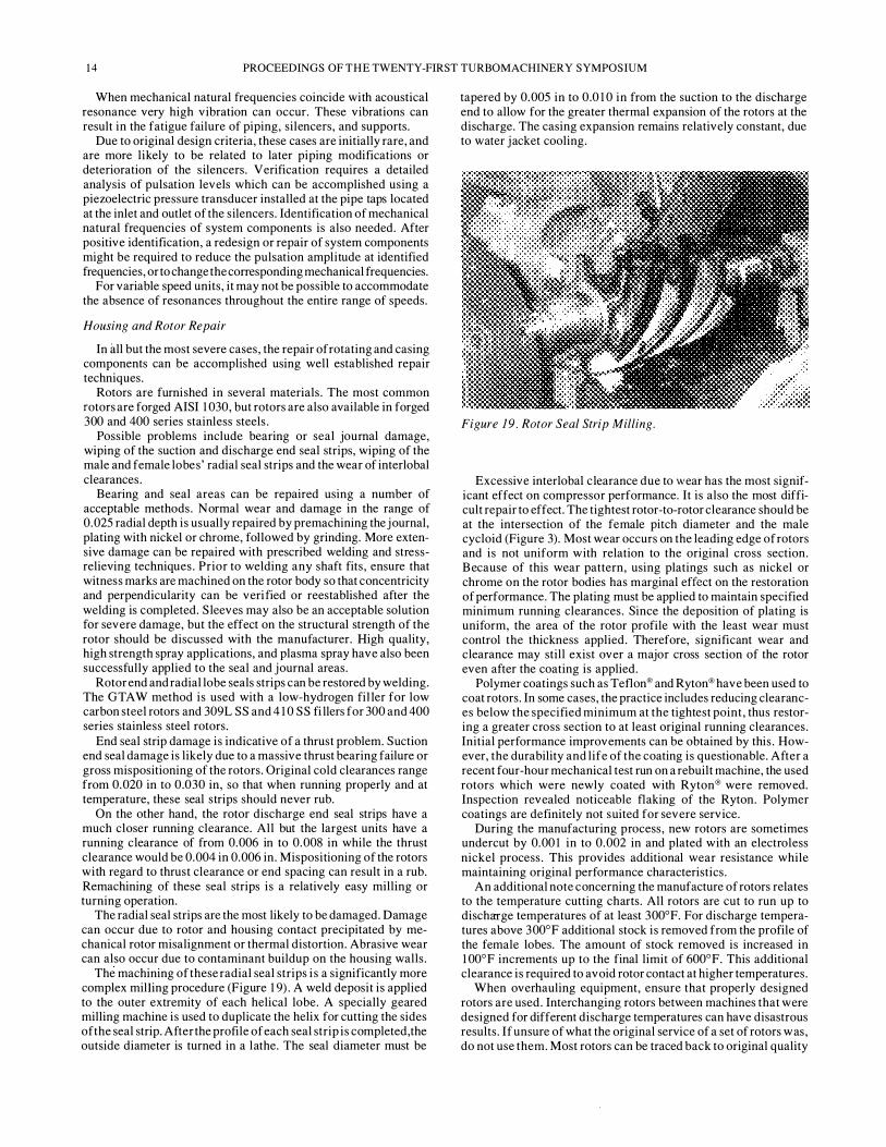
The machining of these radial seal strips i s a significantly more complex milling procedure (Figure 1 9) . A weld deposit is applied to the outer extremity of each helical lobe. A specially geared milling machine is used to duplicate the helix for cutting the sides of the seal strip. After the profile of each seal strip is completed, the outside diameter is turned in a lathe. The seal diameter must be
tapered by 0.005 in to 0.0 1 0 in from the suction to the discharge end to allow for the greater thermal expansion of the rotors at the discharge. The casing expansion remains relatively constant, due to water j acket cooling.
Figure 19. Rotor Seal Strip Milling.
Excessive interlobal clearance due to wear has the most significant effect on compressor performance. It is also the most difficult repair to effect. The tightest rotor-to-rotor clearance should be at the intersection of the female pitch diameter and the male cycloid (Figure 3). Most wear occurs on the leading edge of rotors and is not uniform with relation to the original cross section. B ecause of this wear pattern, using platings such as nickel or chrome on the rotor bodies has marginal effect on the restoration of performance. The plating must be applied to maintain specified minimum running clearances. Since the deposition of plating is uniform, the area of the rotor profile with the least wear must control the thickness applied. Therefore, significant wear and clearance may still exist over a major cross section of the rotor even after the coating is applied.
Polymer coatings such as Teflon® and Ryton® have been used to coat rotors. In some cases, the practice includes reducing clearances below the specified minimum at the tightest point, thus restoring a greater cross section to at least original running clearances. Initial performance improvements can be obtained by this. However, the durability and life of the coating is questionable. After a recent four-hour mechanical test run on a rebuilt machine, the used rotors which were newly coated with Ryton® were removed. Inspection revealed noticeable flaking of the Ryton. Polymer coatings are definitely not suited for severe service.
During the manufacturing process, new rotors are sometimes undercut by 0.00 1 in to 0.002 in and plated with an electroless nickel process. This provides additional wear resistance while maintaining original performance characteristics.
An additional note concerning the manufacture of rotors relates to the temperature cutting charts. All rotors are cut to run up to discharge temperatures of at least 300°F. For discharge temperatures above 3 00°F additional stock is removed from the profile of the female lobes. The amount of stock removed is increased in 1 00°F increments up to the final limit of 600°F. This additional clearance is required to avoid rotor contact at higher temperatures.
When overhauling equipment, ensure that properly designed rotors are used. Interchanging rotors between machines that were designed for different discharge temperatures can have disastrous results. If unsure of what the original service of a set of rotors w as, do not use them. Most rotors can be traced back to original quality

DRY SCREW COMPRESSORS IN PROCESS GAS APPLICATIONS INCLUDING MAINTENANCE CONSIDERATIONS 15
documentation, if the serial number i s known and the manufacturing control number is still legible on the stub shaft.
Main casings are provided in cast iron, cast steel, and cast steel with welded stainless steel overlay.
Casing problems occur infrequently and are usually related to the most severe service conditions . Casing wear and cracking are the most common problems encountered.
Rotor rubbing has little effect on casing bore diameters due to the sacrificial design of the seal strip. The major causes of case wear are corrosion and erosion.
Repair of cast steel cases are relatively easy . Qualified weld procedures are available for complete weld overlays of the bore. The 300 series stainless s teel alloys are the preferred filler metal. These require minimal preheat and interpass temperatures and no post-weld heat treat cycle. Once the buildup i s completed, the bores can be remachined to original tolerances in a horizontal mill . Grinding is not required.
B ore restoration for cast iron is a more complicated project. Chrome and nickel plating are the most common repairs. Proper case preparation is essential for both. The bores must be premachined to a uniform overs ized diameter. Any chemical contamination of the bore must be arrested. This may include neutralizing with chemicals or baking the case. Once the casing is properly prepared, the plating can be applied. B oth plating processes require finish grinding. Upon completion, the plated case will be superior to the original cast iron design for general wear and corrosive service.
Plating repairs are limited to approximately 0.020 in buildup per side for hard chrome and nickel. For processes using soft nickel such as nickel chloride, repairs are feasible to 0 . 1 00 in per side.
Improvements in cast iron welding procedures have brought the possibility of a successful overlay into realistic consideration, although no actual use of the application for oil free screws comes to mind. The procedure must include an analysis to accurately identify material components. B ased upon this analysis, specific rod and heat treatment cycles would be selected. Preheating up to 1 000°F might be required. As with plating, the treatment of the case to ensure that all contaminants are removed is essential. The process is complicated and relatively expensive . Its potential application would be for units with excessive wear that are not within plating limits, and when the availability of a new case is time-prohibitive. As a user, be prepared to assume some risk in the early stages of such an application.
Initial casing inspection should include magnetic p article or dye penetrate inspection for crack detection. The casing should also be hydrotested during the inspection to identify cracks which extend into the water j acket.
Once again, cast steel cases can easily be repaired by welding. Each crack should be ground completely out prior to welding . After the weld is completed the weld can be hand-ground and blended into the surrounding bore.
Cast iron cases require special attention. Welding cracks with special rods and oxyacetylene techniques have been used with mixed success . Examination of weld repair sites during subsequent overhauls often show numerous cracks emanating from the heat affected zone of the repair. Such cases are probably the result of erroneous material analysis, casing contamination, the wrong rod selection, the wrong preheat procedure, or a combination of all the above. In other words, give careful consideration to the specified procedures and qualifications of your selected supplier.
Metal locking of cracks in cast iron cases has proven to be very dependable. Compressor discharge temperature limitations in the most extreme services are still well below the 800°F to 1 000°F experience level for this repair technique .
From a maintenance standpoint, the specification of a cast steel casing during initial purchase or as a replacement for a cast iron
case in a severely corrosive or erosive service will certainly simplify the repair alternatives, and in the long run can be more cost effective.
Most repairs to rotor and casing components located in the gas stream have one goal in mind-improving or restoring volumetric efficiency. Volumetric efficiency is the ratio of the volume of the gas actually being delivered by the compressor vs the volume which should be delivered, based upon the theoretical intake volume per revolution.
Gas leakage or "slip" back to suction i s responsible for the reduction in volumetric efficiency. High pressure gas returns to the suction via the discharge end clearances, interlobal clearances, and rotor lobe to casing clearances. As speeds are reduced, the volume drops off proportionately; however, the leakage due to the internal clearances remains virtually constant, therefore, volumetric efficiency deteriorates w ith reductions in speed.
Early testing by SRM revealed the relationship between internal clearances and volumetric efficiency . Increasing clearances produced the expected results of reductions in volumetric efficiencies. Progressively increasing the internal clearances on the test model produced the expected results of lowered volumetric efficiency at identical speeds .
The test data was correlated to a cumulative variable for all internal clearances designated as E. E /D (the ratio of internal clearances to rotor diameter) is used by manufacturers to predict volumetric efficiency for a particular model.
The values established for are empirical and do not offer a basis to compare the relative importance of the individual clearance components ' contribution to the overall effect (Figure 20) .
( % ) >- , 00
u z 00 w .... 90 u ....
10 "-"-w 60
u 50 .... 0: •o f-w 30 :::! :::> ..J zo 0 > ' 0
200 .250
T I P SPEED
E / 0 0 . 8 X 1 0 - 3 I . 2 X , o - 3 I . 6 X 1 0 · 3 2 . 0 X 1 0 " 3
sso 400 450 ( F T /SEC )
FOR A TYP I CAL MED I UM PRESSUREl RAT I O A I R MACH I NE __j Figure 20. Volumetric Efficiency vs Tip Speed for Varied Internal Clearance Ratio
As stated earlier, very effective repairs are available for the radial lobe seal strips which control the rotor-to-housing bore clearance, along with the rotor end seal strips which control the discharge and suction end wall clearances. However, only marginally effective procedures exist to restore the integrity of the lobe profiles which control the interlobal clearances .
Therefore, expectations of�t:,StMing original efficiencies to a rebuilt machine are dependent upon the condition of the lobe profile.
In an attempt to quantify , the importance of the interlobal clearances to efficiency, a test program has been initiated. The original test flow is used as the control for expected flow . Testing conditions ( i .e . , gas, temperatures, pressures) are duplicated from the original tests .

1 6 PROCEEDINGS O F THE TWENTY-FIRST TURBOMACHINERY SYMPOSIUM
Four units have been tested thus far. All four machines have had the rotor to housing and end wall clearances restored to original specifications. Two of the unit ' s rotors were coated to reestablish interlobal clearances to at least a portion of the lobe profile. The two units without coating (a 1 05 L and a 1 32 L) tested 1 8 percent low and 1 0 percent low on flow as compared to the original test. The two units which were coated (both 1 05 L compressors) tested 20 percent low and 21 percent low on expected flow. The varying severity of the interlobal wear among the different units apparently accounts for the ranges recorded.
At this point, two preliminary assumptions can be put forward. First, the effect of interlobal clearance wear on volumetric
efficiency is extremely significant. Secondly, coating rotor bodies is not an effective means of performance restoration.
These initial readings confirm field reports from customers and service representatives that rebuilt unit capacity often falls well below desired levels. In these cases, the cumulative effect of restoration of the seal strips and plating appear to enhance efficiency in the five to ten percent range.
Because the lobe wear pattern varies from unit to unit, it will be very difficult to establish a definitive correlation between what is or is not acceptable wear by measuring or attempting to measure the piece.
At present, a far more effective means of determining the performance-related repair requirements of a unit is the onsite monitoring of capacity. Users should establish a preliminary baseline flow at startup. If this flow deteriorates significantly below 10 percent of the original flow, new rotors may be required to reestablish acceptable flows.
If the units have been running and baseline data are not available, users should consider a performance test run at a properly equipped test facility so that the unit ' s condition can be compared to original test data.
Most qualified repair shops can take 30-year old rotors and extend their mechanical life indefinitely; however, a 20 to 30 percent capacity restoration can easily justify the cost of new rotors when a performance problem has been identified.
Practical Tips for Startup Operation, Field and Shop Overhaul
All manufacturers provide instruction manuals with their originally supplied equipment. Although the clarity and organization of the manuals may vary widely, all the information required to start up, run and maintain the units is most probably there. The following is intended, from a serviceman ' s point of view, to offer some insights into the equipment not normally found in these manuals.
All manuals will tell the user to rotate or bar over the compressor prior to startup-especially prior to restarting a machine which has been running. Uneven cooling of the rotors and casing can cause a lockup or rub.
Contaminant buildup can solidify during an extended shutdown causing rotor lockup as well. Also, rust and debris from worn out silencers or worn out piping can rain down into the suction and discharge of the compressor.
After a period of trouble free service, complacency can set in and operations people will sometimes phase out the rotation process. This is often due to the extra effort required to access a satisfactory location to bar over the machine. If the process requires numerous starts and stops, a turning lug could greatly reduce the time and effort required.
The best location for the lug is on the suction end of the female rotor. The lug should have an alignment fit machined to ensure concentricity when bolted to the end of the shaft and should be assembly balanced with the female rotor. A cylindrical guard is used in place of the original end cover plate.
Another consideration at startup is bearing loading. A 1 0 to 1 2 psid back pressure should b e developed i n the system a s soon as possible to ensure positive radial and thrust loading. Otherwise, the rotors can exhibit unstable operation and high vibration with possible inactive thrust bearing and discharge end seal damage.
Also verify that the discharge line is not blocked in. Even with a check valve in place, it is possible to develop enough back pressure with sufficient volume in the silencer and a short run of pipe to cause a reverse rotation of the compressor.
High process temperatures are often the cause for shutting down and overhauling oil free screw compressors. Such problems are most often related to the compressor' s increased interleakage or "slip" and the corresponding drop in volumetric efficiency.
For units driven by a steam turbine, the operational fix is as simple as increasing the speed as necessary, up to the operating limits of the compressor. This will increase the flow, therefore reducing the proportional leakage and operating temperature.
Motor driven units naturally have less latitude, but one viable alternative is liquid injection. If the process can tolerate liquids , the oil free screw compressor itself can readily handle significant quantities of injected fluids (Figure 7 ) .
Fluid injection offers two benefits to the compressor. First, the fluid itself produces cooling of the process gas. Second, the fluid tends to close internal clearances which reduces leakage and correspondingly increases volumetric efficiency as much as three percent.
The liquid can be injected at the inlet flange. There are several drilled and tapped holes at this location, which are normally available. The liquid should be sprayed into the inlet nozzle. Rates of up to 3 .0 gal/1 000 cfm of gas are not uncommon.
After extensive service, two stage compressor trains can exhibit overheating, due to a volume mismatch of the two units. The second stage unit is more likely to experience excessive wear due to erosion and corrosion associated with condensate carryover from the intercooler and separator. This can lead to a disproportionate drop in the second stage compressor' s volumetric efficiency.
If the second stage is weak in relation to the first stage, a higher than expected interstage pressure w ill be evident. The first stage compressor will exhibit higher than normal discharge temperatures due to the increased internal recirculation associated with the higher pressure ratio. The interstage pressure and first stage discharge temperature can be reduced through the introduction of a bypass line from the downstream side of the interstage cooler, back to the first stage suction. The bypass line should be sized to allow enough gas recirculation to match the suction requirements for the second stage with some additional capacity for continued weakening of the stage. This provision for future capacity requires the addition of a throttling valve. The compressor manufacturer can assist with the proper sizing of the bypass line.
Overheating can also be due to poor cooling water c irculation. Prior to performing a major overhaul, verify that sedimentation or scaling have not blocked water ports or reduced the water jacket cross section. Online monitoring of differential water temperature and pressure can signal potential problems.
A water jacket inspection should be a part of any overhaul. Depending upon the level of buildup, mechanical cleaning may be sufficient, however, chemical softening and removal of scale may be warranted.
Field overhauls are usually limited to a partial inspection of the rotors and case through the discharge and suction nozzles , bearing inspection, seal inspection, and timing gear inspection.
Interlobal clearances can be measured in place once the silencers have been removed. The interlobal clearances can only be accessed through the discharge port. Position the rotors so that the leading and trailing edge of the male lobe can be accessed at the same time. Thrust rotors to ride on active thrust bearings and take

DRY SCREW COMPRESSORS IN PROCESS GAS APPLICATIONS INCLUDING MAINTENANCE CONSIDERATIONS 17
out the timing gear slack. Using long feeler gauges, check the clearance of the trailing edge first. The tightest area should be at the outer extremity (pitch diameter) of the female lobe as it intermeshes with the male lobe (Figure 3 and Figure 2 1 ) . Leave the feeler gauge in the trailing edge when measuring the leading edge. This will prevent clearance errors due to rotor movements . Establish a reference mark in the case, so that each lobe can be checked in the same way. Always tum the machine in the direction of rotation. There are twelve possible lobe combinations. It will require three complete rotations of the male rotor to verify all l 2 .
Figure 21 . Checking lnterlobal Clearance at the Discharge Port.
Discharge end seal strip clearances can be obtained through the discharge port. Rotor seal strip to casing clearances can also be measured for the top of the case.
S uction end readings are more difficult to obtain since the exposed portion of the rotors are at the bottom of the case. Access i s through the suction nozzle at the top and around the shafts to reach rotor bodies. Measure the rotor to housing clearances at the bottom and check the side clearances as high as possible (normally 45 degrees off the bottom) .
These readings offer some insight into internal wear and can be used to determine the need for further rotor or case repair. However, it should be noted that interlobal clearance may be far worse than is indicated by the limited check of the discharge end. The most serious erosive or corrosive damage associated with increased interlobal clearances occurs at the suction end.
When reinstalling shaft seals, the use of a special tll;pered bushing to properly align the seal with respect to the shaft and housing bore can greatly reduce the chances of 0-ring, carbon ring or labyrinth damage (Figure 22) . Manipulation of a seal in the horizontal position that is required during field installation i s particularly difficult. The resulting damage of a seal that has been forced on i s not obvious until after testing or startup.
The bushing should be made using a soft material such as teflon or micarta. The inner diameter should be 0.00 1 in larger than the bearing j ournal outer diameter (OD) to ensure concentricity with the housing. The outside taper should be sufficient to allow easy starting of the seal ' s inner bore. The large end of the taper should fit flush against the seal shoulder with an OD 0.002 in to 0.003 in larger than the seal j ournal . This design will minimize the chance of cutting 0-rings between the seal cage and the housing along with carbon or labyrinth damage which can occur due to interference with the seal shoulder.
A s imilar starter bushing can also ease the installation of the cartridge style tilting pad bearings .
RAD I A L
C L E ARANCE
. 00 1 T O
. 00 1 5
SEAL
JOURNAL
B E A R I 1>15 J OURN .C..L
Figure 22 . Seal Installation Tool.
R A D I AL
C L EARANCE
. 0005
I
S E � L I NS T A L L A T I ON T O O L
Most timing gears are located on the discharge end of the compressor. The female gear is a two piece design to allow for timing adjustment. Once the timing is set, the outer gear is doweled to the inner hub to maintain position (Figure 23 ) . The dowel is normally a hardened pin. There is not sufficient room to push an intact pin through the gear due to the proximity of the thrust bearing retainer. The easiest method of extracting these dowels is to use a long thin chisel to shear the pin off as it is driven towards the thrust bearing. This may require shearing the pin into two to three pieces . Make sure new pins are available .
Figure 23. /ndicator Method for Setting Rotor Timing.
Once the gear dowels and bolts are removed, the outer gear can be easily removed. However, don ' t try to pull it straight off. A slight turning motion opposite the helical angle is all that is required.
A shop overhaul facilitates a more thorough inspection of the rotors and casings and is recommended whenever rotors are to be extracted.
The use of a positioning table which can adequately support the compressor is highly recommended. This minimizes the handling dangers inherent in rigging and manipulating two cranes to tum the machine end to end several times during an overhaul (Figure 24) .
After casing replacement or repair, it is often necessary to relocate the inlet housing to the main casing to ensure proper rotor to housing location. This can be done using a digital mill or dummy rotors . After the process is complete, checking the bore spread, an

18 PROCEEDINGS OF THE TWENTY-FIRST TURBOMACHINERY SYMPOSIUM
Figure 24 . Rebuilt Unit on Positioner Table .
end to end water level comparison, and rotor housing clearance checks should be preformed to verify the results .
The bore spread is confirmed by measuring the distance between shaft centerlines . Pick a location on each end of the machine and mic the distance between the two shafts along with the diameter of each shaft where the reading is taken. Divide the shaft diameters by two and add the results to the distance between shaft to establish the bore spread. A comparison of the bore spreads from end to end should be within 0.001 in to 0.002 in to avoid an excessive taper between the two rotors .
A water level check is similar to the "bore spread" and is used to verify that both rotors are in the same horizontal plane. Shops normally use precision leveled layout tables to facilitate this inspection. However, the check can be made in the field. Level the compressor using the machined surfaces of the suction and discharge nozzles . Pick male and female shaft positions that have identical diameters to their mate. Place a master precis ion level (accurate to 0.0005 in/ft) across the two shafts . Ensure that the level is perpendicular to the shaft using a square. Use feeler gauges under the low end to level the vial. Repeat the procedure on the opposite end and compare the feeler gauge thicknesses. The difference should be within 0.00 1 in to 0.002 in (Figure 25).
Figure 25. Checking "Water Level. "
Verify housing to rotor clearances as previously described. If all these values are consistent, doweling of the inlet housing to the main casing can be completed.
There is also an effective method for locating the inlet head to the casing when specialized fixtures or accurate machine tools are not available. Mic the bores of the main casing and the outside diameters of the seal strip on each rotor. Determine the minimum clearance which these values will produce. Install the rotors into the housing. Wrap the suction end of the rotors with shim stock equal to one-half of the diametrical clearance measured minus one-half the bearing clearance. Install the inlet housing and bearings . Ensure that the rotors are riding on the bearings and dowel the head. Remove the shims, reassemble the machine according to normal procedures verifying bore spreads, water level and end clearances .
CONCLUSION
Dry screw compressors can certainly become "compressors of choice" for many of process gas applications . The user and the compressor manufacturer must mutually assure that all application and operational parameters are thoroughly discussed and evaluated. Consideration must also be given to preventative maintenance, availability and maintenance costs .
Application and Operational Parameters
• Stay within the compressor manufacturer ' s field-proven experience as to flow and pressure ranges.
• Know the potential process gas variables .
· Molecular weights and potential swings in molecular weights during normal, maximum and minimum modes of operation along with what is to be expected for startup and shutdown.
· Potential for entrained liquids, particulate matter and polymer formation in the gas.
· Corrosivity .
• Most processes have operational variables, planned or otherwise, that do effect compressor selection and performance. Be aware of their impact.
· Pressure and temperature swings at inlet and discharge of compressor.
Special requirements for startup and shutdown.
· Flow control range variation required.
• Other factors at plant installation site which may impact on compressor application:
· Screw compressor has a wide degree of adaptability which allows its use with possible existing compressor or process systems either in parallel or series operation.
· Plant utilities and energy balance considerations may dictate a multitude of drive systems which are readily adaptable to screw compressors. Drive systems such as electric motors, steam turbines, diesel or gas fired engines, hot gas expanders, gas turbines, motor/fluid coupling and variable speed motor drivers have been used.
· S crew compressors are not limited as to their installation location. Majority are mounted at grade level but may be mezzanine or elevated-structure mounted. Some have been mounted on offshore rigs or ocean going vessels. No massive foundations are required.

DRY SCREW COMPRESSORS IN PROCESS GAS APPLICATIONS INCLUDING MAINTENANCE CONSIDERATIONS 19
End User Overview of Design, Testing and Operational Monitoring
• Evaluate detailed mechanical design parameters .
· Select materials o f construction suitable for the process gas handled and the operational duty expected.
· Select bearings and seals that are moderately rated for the extremes of operating conditions .
· Perform rotordynamic analysis to assure that there are no harmful torsional and lateral v ibration frequencies within the operating range.
• Perform mechanical and performance tests that simulate to the maximum extent possible the range of conditions expected in field operation.
• Select accessory equipment such as silencers, drive trains, lube systems, seal systems and monitoring equipment that is of the same high quality level as the compressor. A compression system is only as reliable as its weakest link.
Maintenance
• Preventative maintenance.
· Monitor the operation of your compressor train. Increases in v ibration levels, bearing temperature levels and other monitored readouts over those experienced during initial commissioning may be indicative of potential problems and should be investigated.
· If compressor has demonstrated reasonably consistent operation and there are not excursions in monitored data, i t may be assumed that compressor is in good mechanical health . Do not disassemble a compressor just because i t may be called for in a preventative maintenance schedule. More problems are caused by unwarranted disassembly than for any other reason.
• If minor "onsite" repairs or maintenance is required, i t is suggested that the user employ the services of the manufacturer' s service engineers . The service engineers are the technical professional experts and do have the complete and dedicated back up of the manufacturer.
• Major repairs often can be made in the user ' s maintenance shop. However, it may be to the user ' s advantage from the standpoint of time, quality of workmanship and facilities to utilize a repair shop authorized by the compressor manufacturer.
REFERENCES
1 . Dockstader, E. K. and Mitchell, C . J. B . , Compressors for Chemical Processes, AICHE Today S eries, American Institute of Chemical Engineers ( 1 98 3 ) .
2 . Jackson, C . , "Put the Screws t o Your Compressor Applications," Chemical Engineering (September 27, 1 987) .
BIBLIOGRAPHY
Engineering Dynamics Technical Report EDI 85-305, Vibrations in Reciprocating Machinery and Piping Systems, San Antonio, Texas : Engineering Dynamics, 3rd Printing (September 1 989) .
Kanmerer, H . , "The Application of S crew Compressors for Processes in the Chemical and Petrochemical Industries," Proceedings of the Second Turbomachinery Symposium, Turbomachinery Laboratory, Department of Mechanical Engineering, Texas A&M University, College Station, Texas ( 1 972) .
Mitchell, J . S . , Machinery Analysis and Monitoring, Tulsa, Oklahoma: Penn Well Publishing Company, (ISBN 0-87 8 1 4 - 1 45 -6) ( 1 9 8 1 ) .

20 PROCEEDINGS OF THE TWENTY-FIRST TURBOMACHINERY SYMPOSIUM