ds h2 i h1 - broen.com · broen ballomax® user manual - 7 fig. 5. fig. 7. fig. 6. 4. installation...
TRANSCRIPT

i
H1
H2
L
DH
D
ds
BallomaxENERGY EFFICIENCY - DESIGNED TO LAST
BROEN BALLOMAX®
USER MANUALSTANDARD BALL VALVES VERSION 1.0

BallomaxENERGY EFFICIENCY - DESIGNED TO LAST
2 - BROEN Ballomax® User Manual www.broen.com
Read more in the chapter “General information” on page 4.
Warning! Media can be hot and cause burning. Do use safety goggles and gloves.
Read more in the chapter “Installation and welding” on page 7.
Warning! Wrong installation can result in severel damage or that the valve is not functioning correctly. These general instructions do not cover all possible operating scenarios.
For a more specific guidance about the usage of the valve or its qualification at the desired use, please contact BROEN.
Read more in the chapter “Change of gasket set” on page 31.
Warning! Media can be hot and cause burns. Use safety goggles and gloves.

BallomaxENERGY EFFICIENCY - DESIGNED TO LAST
BROEN Ballomax® User Manual - 3www.broen.com
Content
BROEN Ballomax® User manual
1. General information. . . . . . . . . . . . . . . . . . . . . . . . . . . . . . . . . . . . . . . . . . . . . . . . . . . . . . . . . . . . . .4
2. Transportation and storage . . . . . . . . . . . . . . . . . . . . . . . . . . . . . . . . . . . . . . . . . . . . . . . . . . . . .5
3. Instructions and precautions before installation and operation. . . . . . . . . . .6
4. Installation and welding. . . . . . . . . . . . . . . . . . . . . . . . . . . . . . . . . . . . . . . . . . . . . . . . . . . . . . . . .7
5. Commissioning and use . . . . . . . . . . . . . . . . . . . . . . . . . . . . . . . . . . . . . . . . . . . . . . . . . . . . . . . . .8
6. Service . . . . . . . . . . . . . . . . . . . . . . . . . . . . . . . . . . . . . . . . . . . . . . . . . . . . . . . . . . . . . . . . . . . . . . . . . . . . .9
7. Maintenance. . . . . . . . . . . . . . . . . . . . . . . . . . . . . . . . . . . . . . . . . . . . . . . . . . . . . . . . . . . . . . . . . . . . . . .9
8. Scrapping . . . . . . . . . . . . . . . . . . . . . . . . . . . . . . . . . . . . . . . . . . . . . . . . . . . . . . . . . . . . . . . . . . . . . . . . 10
9. Appendix . . . . . . . . . . . . . . . . . . . . . . . . . . . . . . . . . . . . . . . . . . . . . . . . . . . . . . . . . . . . . . . . . . . . . . . . 11
BROEN Ballomax® – further useful information
10. Mounting and disassembly of gears on a valve as well adjustment . . . . 12
11. User Manual for BROEN Ballomax® hot tapping tool . . . . . . . . . . . . . . . . . . . . . 16
12. User Manual for BROEN Ballomax® branching valve . . . . . . . . . . . . . . . . . . . . . 20
13. Instructions for transportable gears. . . . . . . . . . . . . . . . . . . . . . . . . . . . . . . . . . . . . . . . 22
14. Flexible extensions and planetary gear for underground valves. . . . . . . 25
15. Change of gasket sets. . . . . . . . . . . . . . . . . . . . . . . . . . . . . . . . . . . . . . . . . . . . . . . . . . . . . . . . . 31

BallomaxENERGY EFFICIENCY - DESIGNED TO LAST
4 - BROEN Ballomax® User Manual www.broen.com
1. General information
BROEN Ballomax® Steel ball valvesBROEN Ballomax® is designed with highest possible safety and functionality in mind,
but we recommend reading this manual thoroughly.
The technical data is not binding and can be changed without any notice. Please
see our general terms and conditions. Further information can be obtained upon
request. It is the responsibility of the project owner and installer to choose products
suitable for the intended purpose and secure that pressure data and performance
data is not exceeded. Updated installation manuals apply.
The entire system should be depressurized and emptied before any kind of removal,
change or repair of a single component – no matter if the components are defective
or not.
BROEN Ballomax® ball valve is intended for installation in heating-, cooling- and
district heating- installations with treated water, that does not corrode neither
carbon steel nor materials in the O-rings or seals.
The valve house is made in carbon steel and the stem and ball are made in stainless
steel.
The ball seats are made of carbon reinforced Teflon (PTFE). The stem stuffing box is
done with FPM- (Viton) and EPDM- O-rings.
The valve is tight in both directions and can be mounted in both directions.
Local legislation must always be observed.
ApprovalsBROEN Ballomax® ball valves in steel are approved according to the demands in
(PED) 2014/68/EU for pressurized equipment, module H. Module H is the module for
complete quality control.
Quality managementBROEN A/S has been ISO 9001 certified since 2001:2015.

BallomaxENERGY EFFICIENCY - DESIGNED TO LAST
BROEN Ballomax® User Manual - 5www.broen.com
2. Transportation and storage
It is important to check if the valve or its parts has been damaged during
transportation. If there are any transportation damages BROEN recommends
receiving the delivery and then immediately contacting BROEN.
BROEN recommends to control that the delivery is as agreed – number, size, type
and equipment and etc.
Information about damages, defects or irregularities according to the agreement
should immediately be informed to BROEN.
Store the valve in a clean and dry place before installation. Do not remove the
protection caps before immediate installation.
Use lifting straps when lifting larger valves. Do not lift the valve in its actuator, stem or handle (Fig. 1, 2 & 3).
If in doubt about the weight of the valve to be lifted, you can see its weight in the
Ballomax® catalogue or on BROEN’s homepage – www.broen.com. Fig. 2.
Fig. 3.
Fig. 1.

BallomaxENERGY EFFICIENCY - DESIGNED TO LAST
6 - BROEN Ballomax® User Manual www.broen.com
Fig. 4.
3. Instructions and precautions before installation and operation
Present instructions should be carefully reviewed before mounting and operation of
Ballomax® ball valves:
• Control that the valve is suitable and approved for the used media and the
desired application. The valve is not suitable for steam! Here a valve suitable for
high temperatures is to be used.
• Operate the valve, if possible, to ensure that the valve is not defective from
storage or transportation.
• If the valve is used as an end valve in the pipeline, there has to be installed a
pressure tight ending or blind flange after the valve and the valve is to be left in
the open position (Figure 4).
• In order to ensure safe operation the manual gear or actuator cannot be
removed or dismantled, without special precautions are taken, if the valve is
under pressure and/or there is a flow.
• BROEN recommends, that the valve is installed in the pipeline with minimal
vibrations. In the installation it is recommended to avoid stress and to relieve
the valve for exposed longitudinally pressure and tensile load.

BallomaxENERGY EFFICIENCY - DESIGNED TO LAST
BROEN Ballomax® User Manual - 7www.broen.com
Fig. 5.
Fig. 7.
Fig. 6.
4. Installation and welding
WeldingThe pipe line is to be cleaned thoroughly before the installation of the valves, as any
impurities can damage the surface of the valve and seals.
Do not remove the manual gear or actuator from the valve unless it is absolutely
necessary. In the event the manual gear or actuator is to be removed during or after
the installation, then contact BROEN customer service or see instructions in the
chapter “Instruction for mounted gear”.
Electric welding (TIG, MIG) is recommended for all BROEN Ballomax® ball valves in
steel. Valves larger than DN150 should always be welded in the pipe line by means
of electric welding.
Do not overheat the valve during the welding – there is a risk for damage of the
seals. It is recommended, that the welding is done by qualified personnel.
Cool the valve (after welding) before normal use. The valve should only be operated,
when the valve is cooled sufficiently.
The welding is only to be done on the ends of the valve and not on the body of the
valve, as this will damage the seals in the valve.
For further information refer to the guidance on the valve.
The valve can be placed in both vertical and horizontal position, and during the
entire welding process it should be noticed, that the valve must be in open position.

BallomaxENERGY EFFICIENCY - DESIGNED TO LAST
8 - BROEN Ballomax® User Manual www.broen.com
Welding of larger valves ≥ DN 200 full port / DN 250 reduced port.
The valve must remain open during welding to protect the ball.
At risk of overheating there should a pause in the welding process.
The ground connection must not be connected to the valve.
Flange mounting: The valve should only be mounted by qualified personnel and
follow valid norms and standards. The valve should be in open position during
mounting in order to ensure, that dirt and coatings do not ruin the surface of
the seals. The mating surface of the flange on the pipe should be parallel to the
mating surface of the valve. The centerline of the valve and the pipeline should
also be correctly aligned. The length of the valve should be the same as the length
between the flanges in the pipeline also taking account the thickness of the gaskets.
The flanges of the pipeline should be compatible with the flanges on the valve. For
detailed information, please see standard EN 1092-1.
5. Commissioning and operation
After installation of the valve the pipe line should be flushed thoroughly. During this
process the valve is to be open.
Testpressure at commissioningIf a pressure test of the system is needed, the following procautions are to be
considered:
• The building of pressure is to be done slowly and gradually in order to prevent
pressure surge and hammering.
• During the pressure test of the pipeline (1,5 x PN) the valve is to be in the open
position.
• BROEN Ballomax® ball valves are designed to be fully open or fully closed.
Control that the valve is either fully open or fully closed position against the
endstop.
• Take care that the maximum and minimum temperatures, of the valve, is not
exceeded! The maximum operating pressure and minimum-/maximum-
temperatures are shown on the label of the valve.

BallomaxENERGY EFFICIENCY - DESIGNED TO LAST
BROEN Ballomax® User Manual - 9www.broen.com
6. Operation
Handle operated valvesWhen the valve is open the handle flush the pipeline. Fig. A.
Gear mounted valves The valve opens when the gear is turned clockwise. Valves prepared for installation
of gear/actuator. The position indicator at the end of the stem indicates the position
of the ball in relation to the stem.
The opening and closing of the valves are to be done slowly and carefully in order to
prevent pressure surge in the pipe line.
7. Maintenance
The valves do not demand extra service under normal conditions, but to ensure
correct function of the valves, it is recommended to open and close the valves once
yearly.
Correct functionallity of the valve demands correct quality of the water and
installation. The valve house is made in carbon steel and is as such not resistant to
corrosion.
Corrosion from the outside can be avoided be either installing the valve in dry
environment or equip the valve with a watertight insulation or another surface
protection (not oil).
The stuffing box in the stem is designed to last for the lifetime of the valve.
In specially unfavorable conditions minor leakages can occur. This can be solved
with a change of the o-ring, which can be done without draining the valve of
pressure or media.
Be aware of all special conditions and contact BROEN if necessary.
If it is necessary to change O-rings on the stem, BROEN should be consulted for
guidance and safety instructions.
Fig. A.

BallomaxENERGY EFFICIENCY - DESIGNED TO LAST
10 - BROEN Ballomax® User Manual www.broen.com
Gasket sets: Hexagon with dolly:Size: Item nummer:DN20-80 RB DN25-65 FB 600262
DN100 RB DN80 FB 600263
DN125-150 RB DN100-125 FB 600264
DN200 RB DN150 FB 600269
ISO-flange:Size: Item nummer:DN200 RB 600266
DN250-300 RB DN200-250 FB 600265
DN400 RB DN300 FB 600267
DN500 RB DN400 FB 600268
8. Scrapping
Almost every part in BROEN Ballomax® valves are made of reusable materials.
The type of the materials is described on the data sheet of each valve.

BallomaxENERGY EFFICIENCY - DESIGNED TO LAST
BROEN Ballomax® User Manual - 11www.broen.com
9. Appendix
Standard mounted flange for gears – ISO 5211
Reduced port
DN valve Flange type D1 D2 D3 D4 t Boltholes
125 F07 90 55 70 9 13,5 4
150 F10 125 70 102 11 14,5 4
200 F12 150 85 125 13 14,5 4
250 F14 175 100 140 17 17,6 4
300 F16 210 130 165 21 23,5 4
350 F16 210 130 165 21 23,5 4
400 F25 300 200 254 17 27,5 8
500 F30 350 230 298 21 28,5 8
Full port
DN valve Flange type D1 D2 D3 D4 t Boltholes
100 F07 90 55 70 9 13,5 4
125 F10 125 70 102 11 14,5 4
150 F12 150 85 125 13 14,5 4
200 F14 175 100 140 17 17,6 4
250 F16 210 130 165 21 23,5 4
300 F16 210 130 165 21 23,5 4
350 F16 210 130 165 21 23,5 4
400 F30 350 230 298 21 28,5 8

BallomaxENERGY EFFICIENCY - DESIGNED TO LAST
12 - BROEN Ballomax® User Manual www.broen.com
10. Mounting and disassembly of gear on a valve as well as adjustment.
Please read the instructions thoroughly before beginning of the procedures and
contact BROEN, if there are any questions.
The valve is a shut-off valve. The valve is to be left in the fully open or fully closed
position.
Normally the valve is delivered in fully open position. In fully open position the
indicator line on the end of the stem is pointing in the longitudinal axis of the valve.
The operation of the valve (from fully open to fully closed position) is done by
rotating the stem the maximum distance. The distance in gear and valve is 90°.
Note: BROEN A/S recommends, that the gear is mounted and adjusted before the
valve is installed in the pipe line, while there still is free view to the ball inside the
valve. Is the gear mounted and adjusted after the installation of the valve in the pipe
line, then it is no longer possible to control, that the position of the ball is in fully
open or fully closed position. Wrongly positioning of the ball can cause damage on
the seats of the valve and leakage from the valve in closed position.
Disassembly of the gear from the valve1. Close the valve.
2. Remove the four (or eight) mounting screws and lock washers.
3. Remove the gear from the valve.
Mounting of gear on the valve (handwheel or chainwheel)1. Place the gear and the valve in the same position (both open or both closed).
2. Most gearboxes comprise a reduction cone, which is equipped with a key. If
the reduction cone is supplied separately or falls out, the cone has to be fitted/
placed correctly.
3. Choose the wanted mounting position of the gear box. Activate the gear box
with the valve stem and put the gear box in position upon the valve.
4. Mount the gear box (and if necessary also on insulation gasket) upon the valve
by means of the four (or eight) mounting screws.
Do not forget the lock washers!

BallomaxENERGY EFFICIENCY - DESIGNED TO LAST
BROEN Ballomax® User Manual - 13www.broen.com
Tighten the screws as shown in table A below.
Tabel A - Torque
Fastener dimension M6 M8 M10 M12 M16 M20 M30 M36
Bolt dimension: Steel
8,5 Nm 20,5 Nm 41 Nm 71 Nm 170 Nm 350 Nm 1190 Nm 2100 Nm
Bolt dimension:: Galvanized steel (klass 70)
5,9 Nm 14,5 Nm 30 Nm 50 Nm 50 Nm 244 Nm 445 Nm 651 Nm
5. Adjust the open and close position stop as shown in the following chapter
“Adjustment of gear after mounting upon the valve”.
Adjustment of the position end screwsFig. T.1 overview of components.
The open and close position stops prevent the actuator of rotating beyond the
open and closed positions of the valve. Each stop can be adjusted. The stops are not
preadjusted by the gear box manufacturer. We refer also to the instructions of the
valve for specific demands of the closed position of the valve.
Adjustment of gear after mounting on valveSize DN10-DN150How to adjust the stop for closed position1. Remove the protection cap (A) from the counter nut on the stopscrew for the
closed position.
2. Loosen the counter nut (B) on the end screw for the closed position and loosen
the end screw a few turns.
3. Turn the handwheel (or another operating device) so the valve is in closed
position.
4. Turn the stopscrew for the closed position clockwise until there is a feeling of
resistance from the end screw, when it is in contact with the gear in the actuator.
5. Hold the end screw so it does not turn, when the counter nut (B) is tightened.
6. Put the protection cap back (A) on the counter nut.
BallomaxENERGY EFFICIENCY - DESIGNED TO LAST
14 - BROEN Ballomax® User Manual www.broen.com
Fig. 8.
Fig. 9.
Fig. 10.
Fig. 11.
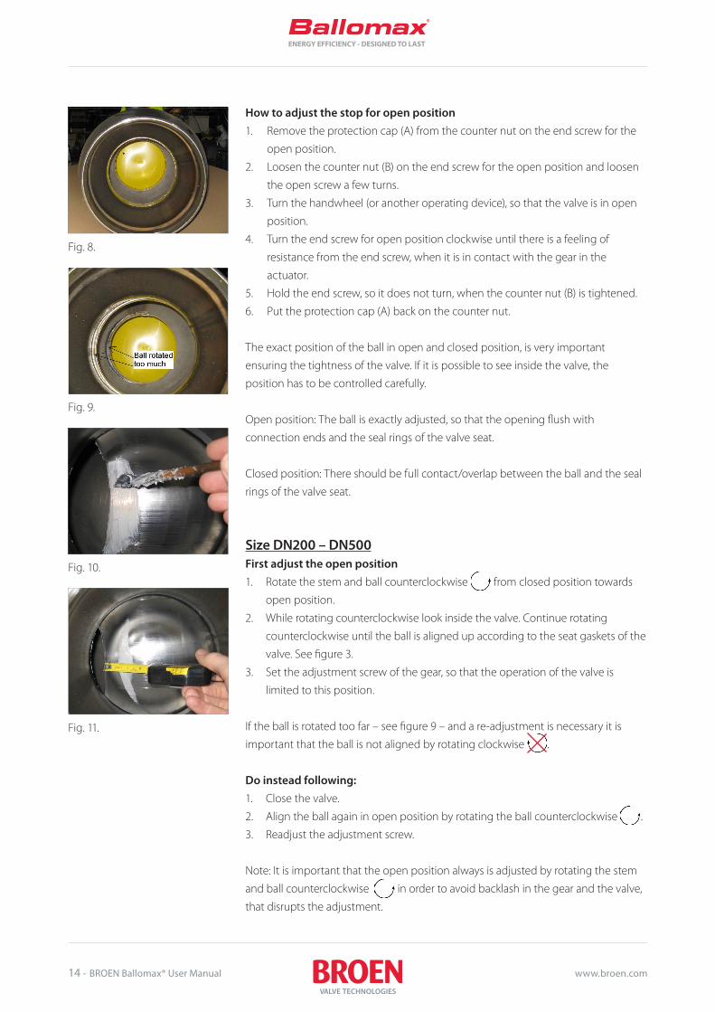
How to adjust the stop for open position1. Remove the protection cap (A) from the counter nut on the end screw for the
open position.
2. Loosen the counter nut (B) on the end screw for the open position and loosen
the open screw a few turns.
3. Turn the handwheel (or another operating device), so that the valve is in open
position.
4. Turn the end screw for open position clockwise until there is a feeling of
resistance from the end screw, when it is in contact with the gear in the
actuator.
5. Hold the end screw, so it does not turn, when the counter nut (B) is tightened.
6. Put the protection cap (A) back on the counter nut.
The exact position of the ball in open and closed position, is very important
ensuring the tightness of the valve. If it is possible to see inside the valve, the
position has to be controlled carefully.
Open position: The ball is exactly adjusted, so that the opening flush with
connection ends and the seal rings of the valve seat.
Closed position: There should be full contact/overlap between the ball and the seal
rings of the valve seat.
Size DN200 – DN500First adjust the open position 1. Rotate the stem and ball counterclockwise from closed position towards
open position.
2. While rotating counterclockwise look inside the valve. Continue rotating
counterclockwise until the ball is aligned up according to the seat gaskets of the
valve. See figure 3.
3. Set the adjustment screw of the gear, so that the operation of the valve is
limited to this position.
If the ball is rotated too far – see figure 9 – and a re-adjustment is necessary it is
important that the ball is not aligned by rotating clockwise .
Do instead following:1. Close the valve.
2. Align the ball again in open position by rotating the ball counterclockwise .
3. Readjust the adjustment screw.
Note: It is important that the open position always is adjusted by rotating the stem
and ball counterclockwise in order to avoid backlash in the gear and the valve,
that disrupts the adjustment.

BallomaxENERGY EFFICIENCY - DESIGNED TO LAST
BROEN Ballomax® User Manual - 15www.broen.com
In cases where the disassembly or mounting of valves with electric actuators is
needed – follow carefully the instructions in the guidelines of the actuator or
contact BROEN.
Reduceret flow Full flow Maximum output torque from gear [Nm]
DN250 DN200 1500
DN300/350 DN250 3000
DN400 DN300/350 6500
DN500 DN400 16000
Ventil DN250 DN300 & DN350 DN400 DN500
Mål 21 mm 28 mm 34 mm 43 mm

BallomaxENERGY EFFICIENCY - DESIGNED TO LAST
16 - BROEN Ballomax® User Manual www.broen.com
11. User manual for BROEN Ballomax® hot tapping tool.
Fig. 1
Important: If hot tapping valves are used on systems with temperatures over 100°C, steam can
be generated, which is led out through the flush valve. Be aware of the danger of
burn.
After welding of the hot tapping valve upon the pipe line it is recommended to
make a tightness test of the weld. For this a test plug is needed and this is supplied
with the case.
BROEN Ballomax® hot tapping tool
DN Vare nr. L D2 H D1 Tilsvej-sende
Gevind f. kobl. 5kt. Nøgle DIA.
Kugle Bor dia. Anbefa-let RPM
15 68102015 127 ø23 53 ø42,4 ø21,3 G 7/8 5mm ø15 ø14 400
20 68102020 127 ø23 53 ø42,4 ø26,9 G 7/8 5mm ø15 ø14 400
25 68102025 143 ø28 63 ø51 ø33,7 G 1 1/8 5mm ø20 ø19 300
32 68102032 145 ø33 68 ø57 ø42,4 G 1 1/2 5mm ø25 ø24 300
40 68102040 178 ø42 96 ø76,1 ø48,3 G 1 3/4 7mm ø32 ø30 250
50 68102050 198 ø52 107 ø88,9 ø60,3 G 2 1/4 7mm ø39 ø37 200
65 68102065 205 ø54 118 ø108 ø76,1 M64x2 8mm ø49 ø48 200
80 68102080 200 ø80 137,5 ø127 ø88,9 M76x2 8mm ø63 ø60 150
100 68102100 225 ø97 163,2 ø152,4 ø114,3 M95x2 *10/12mm ø78 ø76 125

BallomaxENERGY EFFICIENCY - DESIGNED TO LAST
BROEN Ballomax® User Manual - 17www.broen.com
Fig. 14.
Fig. 13.
Hot tapping procedure for DN15 and DN20 BROEN Ballomax® hot tapping valve:Put a 14mm drill in the drilltool and pull the drill all the way back in the house. The
drill can if necessary be held by the means of the stuffing box screw.
Mount the hot tapping tool upon the valve. It should be ensured, that the hot
tapping valve can be closed. Open the hot tapping valve and push the drill to the
contact with the pipe line.
Mount the drilling machine. A hose is mounted on the flush valve in order to lead
the district heating water and chips away from valve.
Open the flush valve.
Decide the revolutions of the drilling machine from the delivered table.The drilling should be done with frequently interruptions to protect the drill and to
secure, that only small chips are created, which much easier can be flushed away.
When the drilling is complete, the drill is pulled all the way into the hot tapping tool.
The hot tapping valve can now be closed. If a chip blocks the close of the valve, the
ball is turned 180° back and the valve is closed. The hot tapping tool can now be
dismounted.
The hot tapping installation is now completed.
Hot tapping procedure for DN25, DN32, DN40 and DN50 BROEN Ballomax® hot tapping valve:Each valve dimension uses a coupling in connection with the hot tapping tool.
The same coupling is also used in connection with the test plug for the tightness
test.
The enclosed table shows what dimensions of drill can be used.A drill extension can be used for both types of drill holders.
Fig. 12.
Fig. 15.

BallomaxENERGY EFFICIENCY - DESIGNED TO LAST
18 - BROEN Ballomax® User Manual www.broen.com
The drawing (Fig. 16) shows the hot tapping of a DN25 hot tapping valve.
Mount the coupling on the hot tapping tool. Mount the correct drill. Remember that
the pilot drill should only be showing app. 4mm. Pull the drill all the way back in the
hot tapping tool.
Mount the hot tapping tool on the valve. It is to be ensured that the hot tapping
valve can be closed. Open the valve full and push the drill forward until contact with
the pipeline. Open the flush valve. Mount the drilling machine.
Decide the revolutions of the drilling machine from the enclosed table. The drilling
is executed with a light pressure on the drill and with frequent interruptions to
protect the drill and release the chips. When the drilling is done, the drill is pulled all
the way into the hot tapping tool.
It is important that fluid pressure is kept on the drill to secure that the drilled part
remains in the cup drill. The hot tapping valve can be closed. If a chip prevent, the
valve in closing, the ball is turned 180° back and the valve can be closed.
Fig. 16.

BallomaxENERGY EFFICIENCY - DESIGNED TO LAST
BROEN Ballomax® User Manual - 19www.broen.com
Fig. 17.
Hot tapping procedure for DN65, DN80 and DN100 BROEN Ballomax® hot tapping valve.These valves have an internal thread for connection of the hot tapping couplings.
The mounting procedure for the connection of the hot tapping tool is similar to the
procedure used for the smaller hot tapping valves.
It is recommended to use the delivered reduction gear and tension unit for hot
tapping with the mentioned valves and use a drilling machine with revolution
control. Hereby a controlled drill operation is obtained with a central pressure on the
cup drill.
It is very important, that the recommended revolutions of the cup drills are
respected. Reduction gear ratio: 7:1.
The figure describes the lineup and how the different components are situated.
In the transport case all the relevant hexagon keys for the mounting and operation
of the different hot tapping valves are found.
IMPORTANT:1. The pilot drill is not to be further out than the cup drill (max. 4mm). Hereby it
can be assured that the valve can be closed, when the cup drill is pulled all the
way back.
2. The flush valve is to be remain open during the hot tapping process to ensure,
that the drilled part is kept in the cup drill, until the valve can be closed.
NB: The appearance of the holder of the cup drill can change appearance pending
on the manufacturer.

BallomaxENERGY EFFICIENCY - DESIGNED TO LAST
20 - BROEN Ballomax® User Manual www.broen.com
12. User manual for BROEN Ballomax® branching valve
BROEN Ballomax® branch valves are used in underground pipe lines, where
extensions of strings are planned.
The branch valve can only be mounted on systems, which are without media and
hereby pressure less. If the pipeline which upon a valve is to be welded is under
pressure, then the BROEN Ballomax® hot tapping valves are recommended to be
used.
The branch valve is not a traditional service valve and if there are more operations to
be done, it is recommended to use BROEN Ballomax® shut off valves instead.
The installation is done by firstly exposing a piece of the pipeline. A hole of the size
of the connection of the branch valve is drilled. After installation a pressure test is
carried out to test the tightness of the welding.
A piece of a pipe is welded on (welding ends) or mounted (threaded ends), which
is closed with a plug. After that, it is ensured that the valve is in fully open position.
The branch valve is mounted on the pipe line and if it is not to be used immediately,
it can be insulated and wait until it is to be used. If the valve is not to be used for
longer period of time, BROEN recommends that the valve is not used as an endstop
valve, but that a plug is mounted after the valve. A longer period of time means
exceeding 1 year before use. The valve can begin leaking with wrong use, as the
seats will be damaged from pressure changes in the pipe line over time.
NB: The branch valves are not be used as end stop valves.
The stem has a notch as position indication of the valve.
When the extension is to be used, the branch valve is closed for work on the pipe
line extended. After work on the pipe line the branch valve is reopened and the
new pipe line is in use.

BallomaxENERGY EFFICIENCY - DESIGNED TO LAST
BROEN Ballomax® User Manual - 21www.broen.com
Instructions for BROEN Ballomax® hot tapping valves and branch valvesThe hexagon for operation of the valve is placed under the conical plug.
This hexagon is marked with the direction of the ball. The operation is done
over 90° from open to close. The operation is done with a hexagon key.
Hot tapping valves and branch valves are not equipped with end stops.
BROEN recommends, that the top conical pipe plug for a short time can be
tightened with PTFE tape and Locktite 577.
After the final operation the top of the valves are to be welded shut permanently.

BallomaxENERGY EFFICIENCY - DESIGNED TO LAST
22 - BROEN Ballomax® User Manual www.broen.com
MPII gear components
1 Dolly 2 Transmissionsgear 3 Power nut 4 Ratchet
MPIII gear components
1 Dolly 2 Transmissionsgear 3 Power nut 4 Ratchet
13. Instructions for transportable gears
BROEN transportable gears is available in two sizes, MPII and MPIII.
MPII with the 70mm hold has a maximum torque of 800Nm and with a 90mm hold
a torque of 1800Nm.
MPIII with the 90mm hold has a maximum torque of 6000Nm.
Preparation:1. The transmissiongear (2) is put together with the dolly (1) and depending on the
use the 70mm dolly or the 90mm dolly is to be used. The power nut is placed in
the dolly.
2. Place the hold (1) together with the transmissiongear (2) and power nut (3) on
the dolly of the valve. Turn by hand the input on the transmissiongear until the
power nut falls in place upon the hexagon of the valve. Take care that all parts
are fitted together on the valve.
3. Place the ratchet (4) on the transmissiongear (2) and extend the lever to increase
the torque input to the gear. On the ratchet the desired direction is chosen.
Right – clockwise – The valve is closed.
Left – counterclockwise – The valve is opened.
4. To ensure an easier transfer of torque to the valve, the transmission function on
the transmission gear has to be activated. In order to activate this transmission
the top of the gear should be raised so the two edges are clear.

BallomaxENERGY EFFICIENCY - DESIGNED TO LAST
BROEN Ballomax® User Manual - 23www.broen.com
IMPORTANT: If you do not secure that item 4 is fulfilled the transmission could be 1:1 and the
operation of the valve could become more difficult.
Opening and closing of the valve:Close:The turning direction is clockwise. To release the ball from the seals and not damage
the seals, you should first turn the valve so far, until you feel a certain resistance in
the ratchet. The occurred torque in the ball will then loosen the ball from the seals
and after a short while you can continue turning clockwise to close the valve.
You continue until you again feel an increasing resistance in the ratchet. Gear and
stem have now stopped against the mechanical stops. The valve is now closed and
secured from reopening by itself.
Open:The turning direction is counterclockwise. The opening of the valve happens in the
same way, as when it is closed.
On the stem of the valve there is a position indicator showing the position of the
ball, which is either open or closed. In this way it can checked if the valve is closed
when the indication shows a closed valve.
Deviations from this can cause damage on the seals and the ball.
Tranportable gear:
Type: Part nummer:
MPII (27/70) 66361100 060
MPII (50/90) 66361250 070
MPIII (50/90) 66361400 080

BallomaxENERGY EFFICIENCY - DESIGNED TO LAST
24 - BROEN Ballomax® User Manual www.broen.com
Measurements for MPII and MPIII complete

BallomaxENERGY EFFICIENCY - DESIGNED TO LAST
BROEN Ballomax® User Manual - 25www.broen.com
Fig. 18.
Fig. 19.
Fig. 20.
14. Flexible extensions and planetary gear for underground valves
Planetary gear is mounted on the valve from the factory. The planetary gear is
hereby adjusted and equipped with a serial number.
The planetary gears belongs to the supplied valves and are not interchangeable.
Correspondingly the hexagon on the valve can be extended with the flexible
extensions 27/70 or 50/90 with standard lengths of 500mm, 1000mm and 2000mm.
In cases where the standard length is not useable, the extension can be shortened.
Regulation of the length of the stem extensionsIllustrated parts and tools are also going to be used:
Fig. 21.
Length calculation of the stem extension:NOTE: This manual is only valid for valves with reduced port. If needed for use on
valves with full port, please contact BROEN.
Calculation example:Adjustment of the standard extension (L=1000m for a ball valve DN200)
Standard stem height on valve (SH): 585mm (The height from the centerline of the
valve to the upper edge on the hexagon)
Requested total height (TH) – (depending on the buried depth of the valve): 1700mm,
measured from the centerline of the valve to the upper edge of the well cover.
The wanted height from well cover to the upper edge of the operation square is
normally 200mm.

BallomaxENERGY EFFICIENCY - DESIGNED TO LAST
26 - BROEN Ballomax® User Manual www.broen.com
The flexible extension is shortened with mm:
Type: Reductions in X mm
TH= 1620 mmMinus -200 mmFKV 1420 mmSH= 585 mmY= 195 mmX= (FKV – (SH+Y)) 640 mmØSL = 1000 mm – X 360 mm
The adjustment of the length of the flexible extensionUsually the flexible extension is supplied with a position indicator strapped on the
stem. This prevents it in displacing during transportation and slide away from the
hexagon dolly on the valve. The position indicator is not used, when the planetary
gear is used and can be removed by unscrewing the socket screws.
1
2
3
4
Fig. 22.
No. Component
1 Stem
2 Position indicator
3 Socket screw
4 Hexagon dolly
5 Internal retaining ring
6 Socket screws
The shortening of the flexible extension:In order to shorten the stem the internal retaining ring has to be removed.
This is done by unscrewing the socket screws in the ring.
Fig. 23.
5
Fig. 24.
6

BallomaxENERGY EFFICIENCY - DESIGNED TO LAST
BROEN Ballomax® User Manual - 27www.broen.com
Reducing the hexagon dolly (the bottim part):
Fig. 25.
Fig. 26.
The surface of the cut should be protected with durable corrosion protection (e.g.
Coldzinc paint, not part of supply).
The shortening of the stainless stem (the upper part) to the wanted length (ØSL):
Fig. 27.

BallomaxENERGY EFFICIENCY - DESIGNED TO LAST
28 - BROEN Ballomax® User Manual www.broen.com
Fig. 28.
Preparation of retaining of the pipe of the hexagon dolly on the valveThree holes of 8mm are drilled with an alteration of 120° on three sides of the pipe
of the hexagon dolly. M8 nuts (part of supply) are welded on. The pipe of the dolly is
retained with screws M8x15.
Alternatively:Three threads are made with an alteration of 120° on three sides of the pipe of the
hexagon dolly. The pipe of the dolly is retained with the supplied screws M8x15.
Corrosion protection has to be applied on the machined parts.
Transfer of the positions indicator on the upper part of the shortened stemMounting of the flexible extension on the valve.1. The planetary gear is released from the valve by unscrewing the pointed screws
on the gear.
2. Mounting of the internal retaining ring on the stem.
3. The extension stem is placed upon the stem of the valve and is retained by
means of three screws.
4. The planetary gear is placed on the stem extension and is retained by means of
pointed screws.
Remember to only loosen the lower pointed screws.
See next chapter for the reinforcement of the stem extension.
Fig. 29.
Fig. 30.
Fig. 31.
Fig. 32.
Fig. 33.

BallomaxENERGY EFFICIENCY - DESIGNED TO LAST
BROEN Ballomax® User Manual - 29www.broen.com
Fig. 35.
Measurement from upper edge of the stem.
NOTE:The insulated protection pipe on the stem of the valve should be shortened (at least
50mm) in order to maintain the accessibility of the pointed screws.
Fig. 36.
Fig. 34.

BallomaxENERGY EFFICIENCY - DESIGNED TO LAST
30 - BROEN Ballomax® User Manual www.broen.com
Fig. 38.
Fig. 39.
Fig. 40.
Fig. 41.
Assembly guide of the reinforcement of the stem extension
Fig. 37.
Reinforcement.
After the shortening of the extension three holes are drilled with 120° on three
sides.
Then the reinforcement is placed. Picture 39.
Hereafter the area for welding is marked. Picture 40.
Prior to the welding the zinc protection is to be removed from the marked area.
After the welding the entire area is painted with zincspray for corrosion
protection and hereafter mounted on the stem. Picture 41.

BallomaxENERGY EFFICIENCY - DESIGNED TO LAST
BROEN Ballomax® User Manual - 31www.broen.com
15. Change of gasket sets
Shown example for BROEN Ballomax® valves DN10-80 RP.Part nummer: 600262.
Step 1:IMPORTANT: Close the valve before the change of the gaskets is started.
1. Loosen topnut with a spanner or similar.
2. Remove the handle.
3. Take out the pin by means of a hammer and mandrel.
Step 2:IMPORTANT: Do not leave any marks or scratches on the stem and stem
guide.
1. Tip the midle ring up.
2. Put the disassembly tool into the o-ring – backup ring – o-ring and pull
them up.
Step 3:Mount the new gasket set.

BallomaxENERGY EFFICIENCY - DESIGNED TO LAST
32 - BROEN Ballomax® User Manual www.broen.com
Step 4:IMPORTANT: Do not squeeze/cut the o-rings on the edge of the stem guide.
Use the supplied mandrel.
1. Carefully put the gasket set in place.
Step 5:1. Put the pin back in.
2. Put the handle upon the stem.
3. Put on the top nut and tighten lightly.
Step 6:Open the valve.

BallomaxENERGY EFFICIENCY - DESIGNED TO LAST
BROEN Ballomax® User Manual - 33www.broen.com
Further gasketsetsWithout ISO flange:
Size: Item nummer:
DN20-80 RB DN25-65 FB 600262
DN100 RB DN80 FB 600263
DN125-150 RB DN100-125 FB 600264
DN200 RB DN150 FB 600269
With ISO-flange:
Size: Item nummer:
DN200 RB 600266
DN250-300 RB DN200-250 FB 600265
DN400 RB DN300 FB 600267
DN500 RB DN400 FB 600268

BallomaxENERGY EFFICIENCY - DESIGNED TO LAST
34 - BROEN Ballomax® User Manual www.broen.com

BallomaxENERGY EFFICIENCY - DESIGNED TO LAST
BROEN Ballomax® User Manual - 35www.broen.com

BBM
-STD
-IM-2
018-
01-E
N
BROEN A/SSkovvej 30, DK-5610 Assens, Denmark
Tel. +45 6471 2095 | Fax +45 6471 2495
[email protected] | www.BROEN.com
BROEN Group locationsHeadquarters in Assens, DK
Sales- and productions sites BROEN A/S, Assens (DK)BROEN SA, Dzierżoniów (PL)BROEN LLC, Kolomna (RU)BROEN INC., Houston (US)BROEN OIL & GAS, Suchy Las & Rogoźno (PL)BSM Valves B.V., Breda (NL)Clorius Controls, Dzierżoniów (PL)
Sales companies and offices BROEN, AssensBROEN, StockholmBROEN, HelsinkiBROEN SEI, RomaniaBROEN, BeijingBROEN, SingaporeBROEN, JakartaBROEN, DusseldorfBROEN, MoscowClorius Controls, CopenhagenClorius Controls, Shanghai
BROEN Engineered Valve GroupFor more than 70 years BROEN has been the global leader in the
development and production of valve technology for the control
of water, air, gas and oil. BROEN delivers complete solutions for
HVAC building installations and is a leading supplier of district
energy valves.
We know application and valve technology in depth and in close
dialogue with our customers and partners all over the world we
crea te value and reliability with proven valves offering full quality
assurance.
BROEN is headquartered in Assens, Denmark and is part of Aal-
berts Industries NL.
Read more on: www.BROEN.com