dsc260 digital system controller - jbl professional · dsc-260 m idi s ysex f ormat ... thank you...
TRANSCRIPT

DSC260Digital System ControllerOwners Manual
8500 Balboa Blvd.Northridge, CA 91329

DSC260 Preliminary Owners Manual Revision 0.9
i
TABLE OF CONTENTS
1.0 INTRODUCTION ......................................................................................................................................1
2.0 GETTING STARTED................................................................................................................................2
2.1 UNPACKING..............................................................................................................................................22.2 MECHANICAL MOUNTING .........................................................................................................................22.3 AC POWER CONNECTIONS........................................................................................................................22.4 AUDIO CONNECTIONS...............................................................................................................................22.5 CONTROLLER CONNECTIONS.....................................................................................................................2
3.0 A QUICK START .......................................................................................................................................3
4.0 GENERAL OPERATION..........................................................................................................................4
4.1 LED INPUT BARGRAPHS ..........................................................................................................................44.2 LED OUTPUT BARGRAPH ........................................................................................................................44.3 MUTE .....................................................................................................................................................44.4 STORE(ENTER) AND RECALL....................................................................................................................44.5 PLUS AND MINUS.....................................................................................................................................44.6 LCD DISPLAY SCREEN ............................................................................................................................44.7 ACCESS BUTTONS....................................................................................................................................5
5.0 ULTILITY CONTROL PARAMETERS...................................................................................................6
5.1 STEREO LINK ..........................................................................................................................................65.2 DEVICE CONFIGURATION .........................................................................................................................75.3 DELAY UNITS ..........................................................................................................................................75.4 LOCK OUT...............................................................................................................................................85.5 MIDI CHANNEL .......................................................................................................................................85.6 CONTRAST ..............................................................................................................................................85.7 OEM LOCK.............................................................................................................................................85.8 MIDI DUMP .............................................................................................................................................85.8 PROGRAM DELETE...................................................................................................................................9
6.0 INPUT SECTIONS................................................................................................................................... 11
6.1 INPUT DELAY ........................................................................................................................................ 116.2 INPUT EQ.............................................................................................................................................. 11
7.0 OUTPUT SECTION NAME, SOURCE, DELAY AND POLARITY .................................................... 12
7.1 NAME ................................................................................................................................................... 127.2 INPUT SOURCE....................................................................................................................................... 127.3 OUTPUT GAIN ....................................................................................................................................... 127.4 LIMITER THRESHOLD ............................................................................................................................. 127.5 VARIABLE OUTPUT DELAY..................................................................................................................... 137.5 DELAY LINKING .................................................................................................................................... 147.6 SWITCHABLE POLARITY......................................................................................................................... 14
8.0 OUTPUT CROSSOVER SLOPES AND FREQUENCIES...................................................................... 15
8.1 LOW EDGE FILTER TYPE ......................................................................................................................... 158.2 LOW EDGE FILTER FREQUENCY ............................................................................................................... 168.3 HIGH EDGE FILTER TYPE......................................................................................................................... 168.4 HIGH EDGE FILTER FREQUENCY .............................................................................................................. 16

DSC260 Preliminary Owners Manual Revision 0.9
ii
9.0 ASSIGNABLE EQ ................................................................................................................................... 17
9.1 EQ TYPE .............................................................................................................................................. 179.2 EQ FREQUENCY .................................................................................................................................... 189.3 EQ CUT/BOOST .................................................................................................................................... 189.4 EQ BANDWIDTH ................................................................................................................................... 189.5 MORE THAN YOU PROBABLY WANT TO KNOW ABOUT FILTER/EQ ASSIGNMENT .......................................... 19
10.0 STORE, RECALL AND SECURITY.................................................................................................... 20
10.1 PROGRAM NAMING .............................................................................................................................. 2010.2 PROGRAM STORING ............................................................................................................................. 2010.4 PROGRAM RECALL............................................................................................................................... 2010.5 SECURITY SETTINGS ............................................................................................................................ 21
11.0 TECHNIQUES, TRICKS AND TRAPS................................................................................................ 23
11.1 USE BOTH HANDS................................................................................................................................ 2311.2 OH, WHERE HAS MY OUTPUT GONE?..................................................................................................... 2311.3 DELAYS IN 1, 2, 3 STEPS ...................................................................................................................... 2311.5 I’M TRYING TO ADJUST THE CROSSOVER OR EQ BUT IT WON’T GO AS HIGH OR AS LOW AS I WANT ............ 2311.6 I CAN’T GET THE DELAY TO GO TO IT’S MAXIMUM OF 635 MS ................................................................. 2311.7 I DON’T HAVE ANY LINKED DELAYS, BUT I CAN’T GET THE MAXIMUM 630MS OUT OF THE UNIT ................ 2311.8 “WARNING, NO MORE FILTERS” .......................................................................................................... 2311.9 THE DSC260 HAS A SPLIT PERSONALITY .............................................................................................. 2311.10 START WITH THE BASS ....................................................................................................................... 2311.11 I’VE DONE IT YOUR WAY BUT I NEED MORE EQ ON INPUTS OR OUTPUTS 1 & 2....................................... 24
12.0 SPECIFICATIONS ................................................................................................................................ 25
APPENDIX A: CONNECTOR WIRING INFORMATION......................................................................... 26
APPENDIX B: OUTPUT ASSIGNMENT MATRIX FOR JBL SYSTEMS................................................ 27
APPENDIX C: MIDI IMPLEMENTATION ................................................................................................ 29
DSC-260 MIDI SYSEX FORMAT .................................................................................................................... 29OVERWRITE MEMORY REQUEST.................................................................................................................... 29DELETE ALL REQUEST.................................................................................................................................. 30SYSTEM DUMP REQUEST............................................................................................................................... 30PROGRAM DUMP MESSAGE ........................................................................................................................... 31
APPENDIX D: USER PROGRAM TEMPLETES ....................................................................................... 32

DSC260 Preliminary Owners Manual Revision 0.9
0.0 Safety Information
Explanation of Graphic Symbols
The lightning flash with the arrowhead symbol, within an equilateral triangle, is intended to alertthe user to the presence of insulated “dangerous voltage” within the product’s enclosure thatmay be of sufficient magnitude to constitute a risk of electric shock to humans.
The exclamation point within an equilateral triangle is intended to alert the users to the presenceof important operating and maintenance (servicing) instructions in the literature accompanyingthe product.
CAUTION: TO REDUCE THE RISK OF ELECTRIC SHOCKDO NOT REMOVE COVER.
NO USER SERVICEABLE PARTS INSIDE.REFER SERVICING TO QUALIFIED PERSONNEL
ATTENTION: POUR EVITER LES RISQUES DE CHOCELECTRIQUE, NE PAS ENLEVER LE COUVERCLE. AUCUN ENTRETIEN DE PIECES
INTERIEURES PAR L’USAGER. CONFIER L’ENTRETIEN AU PERSONNEL QUALIFIE. AVIS:POUR EVITER LES RISQUES D’INCENDIE OU
D’ELECTROCUTION, N’EXPOSEZ PAS CET ARTICLE A LA PLUIE OU A L’HUMIDITE.
All DSC260 products are fitted with a detachable power cord (supplied) which connects to the chassis AC connector. Thepower cord has an IEC female connector on one end and a male mains connector on the other end. This cord is suppliedspecifically to accommodate the different safety and electrical code requirements of individual countries. The power cordsupplied with your DSC260 has a 3-pin type plug. Do not cut off or damage the grounding pin.
If you are traveling abroad with your system, test the power mains and be aware of any specific voltage requirements. If youare in doubt, have a qualified electrician inspect and correct the condition. The input voltage and frequency is listed on thelabel near the IEC power input connector. JBL is not liable for product damage sustained by improper AC mains powerconnection.
JBL Professional8500 Balboa Blvd.Northridge, CA 91329U.S.ATel: 1 (818) 894-8850Fax: 1 (818) 830-1220Web: www.jblpro.com
The information contained in this document is confidential and copyright of JBL Professional. To convey its contents, in part or in whole to anythird party without prior written authorization is a violation of the copyright. (c) JBL Professional 1997.

DSC260 Preliminary Owners Manual Revision 0.9
1
1.0 IntroductionThank you for purchasing the JBL DSC260 Digital System Controller, a specialized device designed for overall systemcontrol. It provides electronic crossover, transducer equalization, signal alignment, level matching and protection limiting foryour system. Its advanced design and high quality components, coupled with in-depth acoustical measurements andextensive listening tests, provides superior sonic performance. By integrating the various system control requirements intoone package, the DSC260 offers unparalleled performance for touring, fixed installation and monitoring requirements.
The DSC260 can be set up in many different configurations offering ultimate flexibility. Mono, two way and three waydefaults are included. The user can also program additional configurations such as mono four, five or six way. Otherconfigurations include mono four way with the second input feeding either a separate 2 way systems such as a down fill ordelay cluster. The DSC260 flexibility is only limited by the maximum number of inputs and outputs and the usersimagination.
This manual contains the information necessary to properly set-up and operate your JBL System. The maximum outputcapability of your system and its safe operation depends on the controller’s setting and your chosen amplifiers. Carefullyfollow this manual’s instructions for a long and productive relationship with your system.
The DSC260 contains the following:
* Active crossover filters with up to 48dB/Octave slopes to divide the audio spectrum intoseparate passbands for each transducer. Six outputs can be derived from either of the twoinputs or a sum of both.
* Up to thirty eight bands of parametric or shelving equalization for smoothing system frequencyresponse over the entire bandwidth and to provide uniform high frequency power response.(Dependant upon crossover filter requirements)
* 60 storage registers for individual programs including several JBL specific programs such asArray, Architectural, HLA, SR and DMS.
* Signal delay on inputs and outputs for delay towers and clusters as well as transduceralignment with up to 630 ms in 21 µs steps.
* Output limiters to protect system transducers from overload damage with adjustable thresholdsand automatic attack and release settings based on crossover frequency for full musicaldynamics.
* Convenient front panel controls for channel muting, programming and level information.
Additional Features• Security Lock Out modes for protecting and hiding program settings• Delay units are selectable in meters, feet or milliseconds• Polarity reversal on each output• Digital gain adjustment from -25 to +4 dB• MIDI sysex dump utilities to save and transfer programs between units and archive settings• Mutes on each output

DSC260 Preliminary Owners Manual Revision 0.9
2
2.0 Getting Started2.1 Unpacking: Carefully unpack the controller and inspect it for possible concealed shipping damage. Save the packing in case any
damage is discovered and contact the dealer from whom you purchased the controller. In the event the DSC260 is ever shippedoutside of a rack, keep the packing for reuse.
2.2 Mechanical Mounting: The DSC260 occupies one standard rack space (1U). When mounted in an equipment rack that istransported, it should be supported by a shelf or other equipment to prevent flexing of the mounting ears.
2.3 AC Power Connections: A 3-wire grounded outlet must always be used. The DSC260 will accept input AC from 100 - 240 Volts, 50-60Hz. The DSC260 does not have a power switch and must be shut down by removing the IEC power connector.
WARNING: THIS DEVICE MUST BE GROUNDED!
The ground terminal of the IEC plug is required by wiring codes and regulations. It must always be connected to theelectrical installation safety ground. The DSC260 has carefully designed internal grounding and balanced inputs andoutputs to reduce the chance of ground loops (hum). If hum occurs see Appendix A for suggested correct audio signalwiring and system grounding. Replace fuse only with a new fuse of correct size (20 mm) and rating (T1A250v).
Figure 1 DSC260 Back Panel
2.4 Audio Connections: The DSC260 has two balanced inputs and six balanced outputs that can accommodate both balanced andunbalanced signals and are wired with Pin 2 hot. The two female XLR inputs are balanced, with pin 1 isolated to prevent groundloops. The six male XLR outputs are balanced, with pin 1 connected to ground. Pin 2 or pin 3 can be used as "hot" provided thatthe inputs and outputs are wired to the same standard. Two conductor shielded audio cable should always be used for all inputsand outputs.
Note: Because the DSC260 outputs can be programmed for any passband, caution must be takenwhen connecting the outputs to the amplifiers. Miswiring can connect low frequency information tohigh frequency drivers causing serious damage (not covered by warranty) to the drivers.
2.5 Controller Connections: MIDI in, out and thru jacks are located on the back panel. These allow remote program recall and MIDI sysexdump capability. In addition, an RS-232 connector allows updating of the Flash Memory as software updates become available.More information on these procedures is contained in Appendix C.

DSC260 Preliminary Owners Manual Revision 0.9
3
3.0 A Quick Start
To fully understand the operation and programming of the DSC260, the user should read at least sections 4 through 6. Butsince we know that most users have already plugged the unit in and started to explore, here is a quick start to get you upand running if you have a JBL system that is already programmed in the DSC260.
1. Before making any connections between the controller and the amplifiers, make sure that all power to theamplifiers is disconnected and their level controls are completely down.
2. The DSC260 has been programmed for many popular JBL Speaker System models. Before connecting thecontroller to the amplifiers, this program should be changed to a setting that matches your JBL system.Appendix B lists the various output assignments.
3. Select the appropriate program by powering on the DSC260 then pressing RECALL. Use the Parameter Plusand Minus buttons located on the left side of the LCD panel to page up and down until the correct setting isvisible. Press RECALL after the cursor is on the setting.
4. Connect the console outputs to the inputs of the DSC260. Left to A and Right to B. In the case of a monosystem, use input A.
5. Connect the outputs of the controller to the amplifier input channels maintaining the Left and Right identification.Typically the higher the number of the output, the higher the frequency content. i.e. In a 2 channel 3 waydefault, outputs 1 & 2 are Low, 3 & 4 are Mid and 5 & 6 are High. As the outputs vary depending upon thetype of system and program loaded into the DSC260, consult Appendix B for correct output information.
6. Turn on the power to the console, controller(s) and finally the amplifiers. (It is best to turn the amplifiers on lastand off first to prevent any thumps or pops from damaging the transducers.)
7. Apply a signal source to the controller. This can be pink noise, a tone or music.
8. Unmute the outputs on the DSC260, one at a time. The RED LEDs below each Output Meter signify the outputis muted.
9. Advance each amplifier channel slowly and confirm that the signal reaching the transducers is correct. (It is bestto begin with channels driving the low frequency transducers first. In this way, if the high and low arereversed, high frequency signals will be going to the woofer. It’s better to find this problem than the lowfrequencies going to the high frequency device!)
10. After it is confirmed that all transducers are receiving the proper signals, initial calibration can begin.

DSC260 Preliminary Owners Manual Revision 0.9
4
4.0 General Operation
Figure 2 DSC260 Front Panel
4.1 LED Input Bargraphs The input bargraphs are peak responding to the input signal and also indicates digital clipping. The inputs alwaysshow the input level as calibrated to the XLR inputs. i.e. (+20 dBu=Maximum Input) -3dB, -6dB, -12dB and a signal presentshow the level below maximum input. In addition, the “Clip” lights function both as analog input “Clip” indicators and signal if thereis clipping in the Digital Signal Path. If both A & B “Clip” LEDs flash yet a yellow -3 does not, this would indicate that the DSP isclipping and not the analog input circuitry. This situation would most likely be caused by excessive digital gain or EQ in one ormore outputs.
Figure 3 Output Bargraphs and Mute
4.2 LED Output Bargraphs: The output bargraphs 0dB headroom reference is shifted with respect to the limiter settings. In this way, eachoutput can be set to reflect the specific level below maximum for the respective output. i.e. If a limiter is set to +8, then the“Limit” LED represents an output of +8dBu and the -3, -6 and -20dB LEDs refer to this level and signify +5, +2 and -12dBu,respectively. This relationship remains regardless of output gain settings as the limiters are the final element in the programmingpath. As an example, if a +4dBu signal is routed to an output and the gain is set to 0dB and the limiter is set to +10dBu, then the-6dB Led would light indicating 6 dB of headroom. (+10dBu - (4 + 0)dBu = 6dB)
4.3 Mute: Pressing any of the front panel Mute keys will toggle the respective channel in and out of mute. The LED will reflect the mutestatus. A Red LED on signifies the output is muted.
Figure 4 Store, Recall and Parameter Adjust
4.4 Store(Enter) and Recall: These keys allow the user to store and recall programs from the internal memories. The Store key is alsoused as an Enter Key to confirm certain operations such as a configuration change from 2 way to 3 way, MIDI Dump and OEMhiding which are explained further in Section 5.0 on Utility Control Parameters.
4.5 Plus and Minus: These keys adjust the currently selected parameter up or down. In the case of a non-numeric parameter, these keysscroll through a predefined set of variables.
4.6 LCD Display Screen: This 2 x 16 character LCD displays all required programming information. It is, in effect, a window into a largegrid of adjustable parameters that moves from row to row and column to column. Figure 5 below as well as the back of thismanual is a diagram of the programming grid. Upon turn on, the software revision will also appear briefly. The bottom line showsthe program number and name of the stored program. An asterisk indicates that a program has been edited since the last store.This shown in the top right of the LCD display on all screens except the default.
DSC260 Preliminary Owners Manual Revision 0.9
5
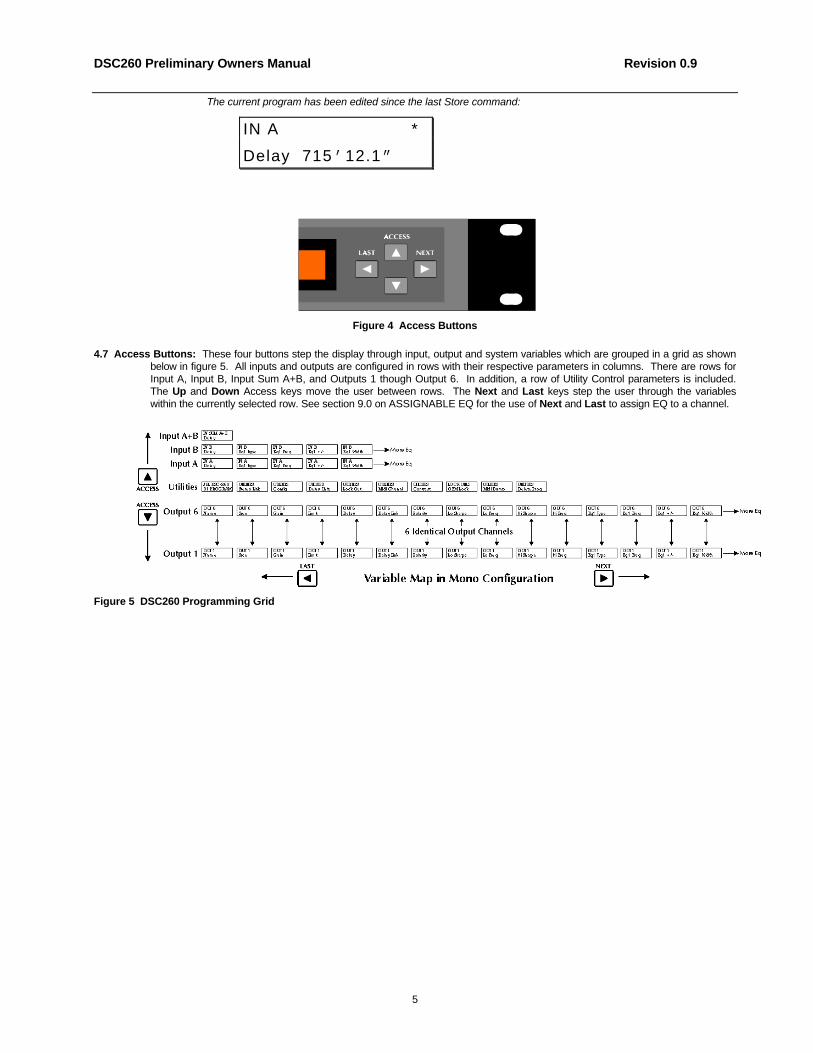
The current program has been edited since the last Store command:
IN A *
Delay 715’12.1”
Figure 4 Access Buttons
4.7 Access Buttons: These four buttons step the display through input, output and system variables which are grouped in a grid as shownbelow in figure 5. All inputs and outputs are configured in rows with their respective parameters in columns. There are rows forInput A, Input B, Input Sum A+B, and Outputs 1 though Output 6. In addition, a row of Utility Control parameters is included.The Up and Down Access keys move the user between rows. The Next and Last keys step the user through the variableswithin the currently selected row. See section 9.0 on ASSIGNABLE EQ for the use of Next and Last to assign EQ to a channel.
Figure 5 DSC260 Programming Grid

DSC260 Preliminary Owners Manual Revision 0.9
6
5.0 Utility Control ParametersTo access the Utilities Row use the Up or Down Access keys to scroll through the rows. Individual Utility parameters arereached by pressing Next and Last from the default screen.
Figure 6 Utility Control Menu Options
5.1 Stereo Link This parameter adjusts the stereo linking of various outputs using the Plus and Minus keys to select between Mono, 2channel x 3 way and 3 channel x 2 way. The linking works with the Configuration parameter located to the right of the StereoLink parameter. In 2 channel x 3 way mode, output pairs 1 and 2, 3 and 4, 5 and 6 are linked. Typically the bass output would beoutput 1 and 2. In 3 channel x 2 way mode Outputs 1, 2 and 3 are typically low and 4, 5 and 6 are high. There are two differentrelationships between linked variables, step and offset. A Step Variable has discrete selections such as filter type, high passslope, polarity, etc. If a Step Variable is changed e.g. high pass slope type, both channel values will be forced to the same valueif linked. Those parameters that don’t have discrete selections such as gain, frequency or delay can have offsets between themwhen the channels are linked. These are called “Offset Variables.” If any linked variable reaches the variable’s limit, none of thelinked variables will be able to move further in that direction. Table 1 detail these relationships.
Link on and off:
UTILITIES
Stereo Link On
Parameter Linking Type 2 Channel 3 Way 3 Channel 2 Way
Input Delay Offset Variable A - B A - B
Input EQ Type Step Variable A - B A - B
Input EQ Frequency Offset Variable A - B A - B
Input EQ +/- Offset Variable A - B A - B
Output Name Offset Variable 1 - 2 1-3
Output Source Offset Variable A - 1, 3 & 5, B-2, 4 & 6 A - 1& 4, B - 2 & 6, A+B - 3 & 5
Output Gain Offset Variable 1 - 2, 3 - 4, 5 - 6 1 - 3, 4 - 6
Output Limit Offset Variable 1 - 2, 3 - 4, 5 - 6 1 - 3, 4 - 6
Output Delay Offset Variable 1 - 3, 3 - 5, 2 - 4, 4 - 6 1 - 4, 2 - 5, 3 - 6
Output Delay Link N/A 1 - 3, 3 - 5, 2 - 4, 4 - 6 1 - 4, 2 - 5, 3 - 6
Polarity Step Variable 1 - 2, 3 - 4, 5 - 6 1 - 3, 4 - 6
Output Lo Shape Step Variable 1 - 2, 3 - 4, 5 - 6 1 - 3, 4 - 6
Output Lo Frequency Offset Variable 1 - 2, 3 - 4, 5 - 6 1 - 3, 4 - 6
Output Hi Shape Step Variable 1 - 2, 3 - 4, 5 - 6 1 - 3, 4 - 6
Output Hi Frequency Offset Variable 1 - 2, 3 - 4, 5 - 6 1 - 3, 4 - 6
Output EQ Type Step Variable 1 - 2, 3 - 4, 5 - 6 1 - 3, 4 - 6
Output EQ Frequency Offset Variable 1 - 2, 3 - 4, 5 - 6 1 - 3, 4 - 6
Output EQ +/- Offset Variable 1 - 2, 3 - 4, 5 - 6 1 - 3, 4 - 6
Eq Width Offset Variable 1 - 2, 3 - 4, 5 - 6 1 - 3, 4 - 6
Table 1 Linked Parameter Relationships

DSC260 Preliminary Owners Manual Revision 0.9
7
5.2 Device Configuration, selectable Mono, 2 channel x 3 way, 3 channel x 2 way. Changing this mode changes the overall routing andlinking of the unit. If the user changes this value, the user will have to confirm the selection as routing, linking, delay linking andband name data will be changed. The unit will also mute to ensure that the user can check that the outputs have appropriatebandwidth settings before continuing. The user can then move to the Output variables and change the routing, delay linking andband names as required. Figure 7 shows the two standard configurations.
Switching to 2 channel x 3 way configuration will force Outputs 1,3 and 5 to be routed from Input A and Outputs 2, 4 and 6 to berouted from Input B. All delay linking will be switched off and Stereo Link will be switched on. Band Names will be forced to ' Low','Mid', 'High', 'Low', 'Mid', 'High' for outputs 1 - 6 respectively. When only 2 way systems are used in stereo, outputs 3-6 are usedfor Low (3-4) and High (5-6). This allows subwoofers to be added on outputs 1 and 2 without rewiring existing systems.
When using a derived center cluster feed such as in L, C, R, the configuration can be changed to a 3 channel 2-wayconfiguration where the center channel is a sum of A and B. This 3 channel x 2-way configuration will force Outputs 1 and 4 tobe routed from Input A and Outputs 3 and 6 to be routed from Input B. Outputs 2 and 5 will be routed from Input A+B. All delaylinking will be switched off and Stereo Link will be switched on. Band Names will be forced to 'Low' and ‘High'.
Switching to Mono configuration will force all Outputs to be routed from Input A. Delay linking will be switched off and StereoLinking will be switched off. Band Names will be forced to 'Band 1' through 'Band 6'.
Configuration:
UTILITIES
Config 3CH 2 way
To change configurations press the Plus and Minus parameter keys to select the desired configuration, mono, 3-way or 2-way.This will call up the dialogue box below that will give you the question “Change to Mono?, 2-way or 3-way.
Change configuration?:
Change to 3 way?
Store to confirm
Pressing store will reconfigure the DSC260 to the desired set-up. Pressing any of the access keys will cancel the operationand return you to the previous configuration.
2 Channel 3 Way Configuration 3 Channel 2 Way Configuration
Figure 7 Linking Relationships
5.3 Delay Units, selectable ms, ft and m: The delay units can be selected for the specific application in milliseconds, feet or meters. UseParameter Plus and Minus keys to select the preferred measurement units. Moving to a different position on the grid willautomatically store this parameter and recalculate the delay values for all displays.
Delay units:
UTILITIES

DSC260 Preliminary Owners Manual Revision 0.9
8
Delay Units ms
5.4 Lock Out selectable On or Off. With Lock Out ON no displayed variables (except Lock Out) can be adjusted. Mutes can still beadjusted. With Lock Out ON, no programs can be stored or recalled. For more information on other lock systems, see section 10- Security.
Lock Out:
UTILITIES
Lock Out Off
5.5 Midi Channel Number; 1 to 16. Midi is used to transmit sysex dump data between units and transmit and receive program change.Use the Plus and Minus keys to adjust the channel number.
Midi channel number:
UTILITIES
Midi Channel 15
5.6 Contrast: The +/- Parameter keys increase/decrease the LCD display contrast. A graphical indication of the variable changing isdisplayed.
Contrast:
UTILITIES
Contrast /
5. 7 OEM Lock. Pressing the Plus button will take the user into the OEM Lock password screen. See section 10 for more information on thisfunction.
OEM Lock:
LOCK UTILITIES
OEM Lock Off
5.8 Midi Dump. This utility is used to dump program information between DSC260 units as well as to any MIDI Sysex capable sequencer orcomputer. Attach a MIDI cable from the MIDI Out of the sending unit to the MIDI In of the receiving unit.
Sending Unit Midi Dump Screen:
UTILITIES
Midi Dump No
Pressing the Plus parameter key on the sending unit will bring up a “MIDI Dump Yes” message with “Store to Confirm?”
Sending Unit Midi Dump screen

DSC260 Preliminary Owners Manual Revision 0.9
9
Midi Dump?
Store to confirm
At this time a Midi sysex message is sent out that prompts a DSC260 receiving unit that an incoming Midi dump will occur andthe receiving unit will display the message below.
Receiving Unit Screen after MIDI Dump Prompt:
Incoming Dump
Allow Dump? Yes
If you do not want the receiving unit to overwrite the memories, press the Minus key on the receiving unit to change the AllowDump message to “No.” If this occurs, then the receiving unit will return to its normal operation and ignore any incoming programinformation.
Pressing Access Up or Down at any time will return the sending unit to the Utility list.
Pressing Store/Enter on the sending unit performs the dump. The screen displays a percentage of the dump performed. SeeAppendix C on MIDI Sysex for additional information.
Midi Dump screen
Midi Dump
50%
5.8 Program Delete. The Plus key enters the program delete screen.
Program delete?:
UTILITIES
Delete Prog No
Select the program using the Plus and Minus Keys.
DELETE
31 4892-90 @
Delete Program?
Store to confirm
5.8.1 The Plus/Minus keys select the program to Delete.
5.8.2 Pressing Access at any time will return to the Default screen.

DSC260 Preliminary Owners Manual Revision 0.9
10
5.8.3 Pressing Store/Enter a second time will delete the program.

DSC260 Preliminary Owners Manual Revision 0.9
11
6.0 Input SectionsOn the DSC-260 there are three input sections; Input A, Input B and Input Sum A+B. When Inputs are linked in the Utility sectionboth Input A and Input B variables are ganged. The sum variables are not ganged with A or B. The input sum of A+B only has aDelay value to edit. All EQ is done on the individual unmixed inputs and then summed into Input A+B.
Figure 8 Input Parameters
Input A delay when in mono mode:
IN A
Delay 630.000ms
Input A+B Sum delay:
IN SUM A+B
Delay 0.000ms
Inputs A and B stereo linked: (Note the ampersand in place of the A + B to indicate stereo linked.)
IN A & IN B
Delay 630.000ms
6.1 Input Delay: There is a main delay 0 - 635ms with 21 µs increments for Input A, Input B and Input A+B. The Plus/Minus buttonsaccelerate in their effect the longer the buttons are held by increasing the size of the steps. To return to the small incrementsettings release the key then press again to begin with 21 µs steps again. Delay units are set in the Utility section. At no timecan there be more than 635.417 ms of delay on any input to output path.
Input A delay in feet and ins:
IN A
Delay 715' 2.9"
Input A delay in meters:
IN A
Delay 218.005m
6.2 Input EQ: Input A and B can have EQ assigned. High and low shelving with 12dB or 6dB/octave slopes as well as full parametric bandare available. See Section 9.0 on Assignable EQ for more information. Input A+B is a sum of inputs A and B after any Input EQ.
7.0 Output Section Name, Source, Delay and PolarityOn the DSC260 there are six output sections; Output 1 through Output 6. When the unit is stereo linked in the Utility Menu,various outputs are linked so that when changing variables such as EQ or Crossover, both channels operate together. In 2channel x 3 way configuration, output 1 and 2 variables, output 3 and 4 variables and output 5 and 6 variables are ganged in

DSC260 Preliminary Owners Manual Revision 0.9
12
pairs. In 3 Channel x 2 way configuration outputs 1, 3 and 5 outputs are linked as are 2, 4 and 6. When outputs are linked, theband name is derived from the channel assigned to the lower numbered output. Similarly, if the linked outputs are effset, theparameter valuse for the lower numbered output is displayed. From the Output parameter rows the Next and Last keys stepthrough the output parameters.
7.1 Name: The Output ‘band’ name is selectable from a pre-programmed list. Use the Plus and Minus parameter keys scroll through thislist.
Output 5 name:
OUT 5
Name High
7.2 Input Source: The combinations are as follows: Input A, Input B or a sum of Inputs A and B denoted as Input A + B. When StereoLinked in 2 channel x 3 way mode, the selections are normally Inputs A & B. Notice the “&” in place of the “+” sign to denote Aand B, not A plus B which signifies a sum of the two inputs.
Output 1 source:
OUT 1 Subs
Source IN A
Stereo Linked Output 1 & 2 source:
OUT 1 & 2 Subs
Source IN A & B
7.3 Output Gain: -25dB to +4 dB in 0.5dB steps. The nominal setting for outputs is -10dBu. The DSC is set-up to operate normally with a -10dB attenuation of the input signal to the least sensitive band. This has been designed to minimize the noise floor for thoseoperators that keep their amplifier gain controls at maximum.
Output 1 gain:
OUT 1 Subs
Gain -15.0dB
7.4 Limiter threshold: -20 to +10dBu. This value is also the output meter reference value. If the Limiter is adjusted to 2.0 dBu as below,then the output 1 meter will represent +2dBu at limit with the -3, -6 and -20 dB reading relative to that level. i.e. -1dBu, -4dBu and-18dBu.
Output 1 limiter threshold:
OUT 1 Subs
Limit 2.0dBu

DSC260 Preliminary Owners Manual Revision 0.9
13
7.4.1 Limiter Level Calculations: The DSC260 comes from the factory with suggested limiter settings for variousJBL systems. These limiter settings are guidelines for use with specific JBL power amplifiers. Thereare two primary uses for these limiters: One is for prevention of amplifier clipping and the second is tolimit the amount of power transmitted to the transducers. When using JBL MPA and MPX poweramplifiers consult the tables in Appendix B for recommended settings for specific amplifiers and powerlevels. For other amplifiers or transducers, the method for setting the limiting threshold is given by thefollowing equation:
Limiting Threshold (dB) = Transducer voltage limit (dBu) - Amplifier gain (dB)
As an example, we first convert a transducer power rating into dBu. Our example transducers has acontinuous power rating of 600 watts. With an impedance of 8 ohms, this corresponds to a voltage of:
Voltage = (600 x 8)0.5 = 69.28 Volts
Expressing this in dBu:
20 log (69.28/0.775) = 39.03 dBu
Next you find the amplifier gain from the published specification in the spec sheet or owner’s manual.For this example, we will use an MPA1100 amplifier which has 38dB of gain and use the formula:
Limiting threshold = 39dBu - 38dB = 1dBu.
This would be the limiter threshold for 600 watts continuous output into the 8 ohm transducer.
7.5 Variable Output Delay 0 - 635ms: The Plus and Minus buttons accelerate in their effect the longer the buttons are held by increasingthe size of the steps. To return to the small increment settings release the key then press again to begin with 21 µs steps again.At no time can there be more than 635.417 ms of delay on any input to output path. Delay units are set in the Utility section from alist of Milliseconds, Meters and Feet/Inches using the parameter keys in the Utility “Delay Units” section. These are displayed asms, m and ft, respectively.
Output 1 delay:
OUT 1 Subs
Delay 600.000msOutputs 2 and 3 stereo linked:
OUT 3&4 Mid
Delay 600.000msOutput 1 delay in feet and inches:
OUT 1 Subs
Delay 11' 12.9”Output 1 delay in meters:
OUT 1 Subs
Delay 3.433m

DSC260 Preliminary Owners Manual Revision 0.9
14
7.5 Delay Linking: This is used to maintain offsets between various channels. Typical uses include setting individual transducer delayoffsets for optimum performance and then linking them. If either linked channel’s delay is changed, the linked channel(s) willfollow and maintain the offset. Normally, the transducer delays are set, then any overall delay for cluster alignment or delay towerset-up. The following table shows the linkable channels in each mode.
Output Mono 2channel x3 way
3 channel x2 way
1 2 3 4
2 3 4 5
3 4 5 6
4 5 6 None
5 6 None None
6 None None None
Table 2 Delay Linking Relationships
Delay Linking:
OUT 1 Subs
Delay Link Off
OUT 1 Subs
Delay Link to 2
7.6 Switchable Polarity - Normal or Inverted. Using the Plus and Minus keys, the user can invert the polarity of the output signal. If thepolarity is changed on a linked output, both outputs will change to the same selection.
Output 1 polarity normal:
OUT 1 Subs
Polarity Normal
Output 1 polarity inverted:
OUT 1 Subs
Polarity Invert

DSC260 Preliminary Owners Manual Revision 0.9
15
8.0 Output Crossover Slopes and Frequencies
The DSC260 allows full control over each high pass and low pass filter of a crossover segment in shape, slope andfrequency. Graphically these parameters are labeled as in Figure 8 below.
vs
-50.00
-45.00
-40.00
-35.00
-30.00
-25.00
-20.00
-15.00
-10.00
-5.000
0.0AMPL(dBu)
20 100 1k 10k 20k
FREQ(Hz)
High Filter Edge Low Filter Edge
Edge Frequency
Figure 9 Filter Edge Identification
8.1 Low edge filter type: Using the Plus and Minus Keys, the Low edge filter type can be selected as Butterworth 12, 18, 24 or48dB/Octave or Linkwitz-Riley 12, 24 and 48dB/Octave. The options are displayed as: BUT 12, L-R 12, BUT 18, BUT 24, L-R24, BUT 48, L-R 48. The screen below show a low edge shape of Butterworth 12dB/Octave on output 5 which is labeled High.The various filter shapes are shown in Figures 11 and 12.
Output 5 low edge type:
OUT 5 High
Lo Shape But 12

DSC260 Preliminary Owners Manual Revision 0.9
16
vs
-50.00
-45.00
-40.00
-35.00
-30.00
-25.00
-20.00
-15.00
-10.00
-5.000
0.0AMPL(dBu)
20 100 1k 10k 20k
FREQ(Hz) vs
-35.00
-30.00
-25.00
-20.00
-15.00
-10.00
-5.000AMPL(dBu)
100 1k 10k
FREQ(Hz)
Figure 10 Linkwitz-Riley 12, 24 and 48dB/Octave Slopes Figure 11 Butterworth 12, 18, 24 and 48dB/Octave Slopes
8.2 Low edge filter frequency: This control adjusts the cut off frequency of the selected Low Frequency Crossover. The range is from15Hz to 16kHz in approximetly 1/6 Octave steps with “Out” at the bottom end and “Off” when adjusted beyond 16kHz.
Output 3 low edge frequency:
OUT 3 Lo/Mid
Lo Freq 220Hz
Note: If the Low edge filter frequency is raised beyond 16kHz, the channel output will be switched off. This isdifferent from “Mute” in that any signal assigned to this output will not indicate on the output meters. Output meterdeflection on unused outputs might confuse an operator.
8.3 High edge filter type: As with the Low edge filter frequency there are selections for Butterworth 12, 18, 24 or 48dB/Octave or Linkwitz-Riley 12, 24 and 48dB/Octave. The various filter slopes are shown in Figures 10 and 11.
Output 3 high edge type:
OUT 3 Mid
Hi Shape L-R 48
8.4 High edge filter frequency: This control adjust the cut off frequency of the selected High Frequency Crossover. The range is from15Hz to 16kHz in approximetly 1/6 Octave steps with “Out” beyond 16kHz.
Output 3 high edge frequency:
OUT 3 Mid
Hi Freq 2.0kHz

DSC260 Preliminary Owners Manual Revision 0.9
17
9.0 Assignable EQEQ is found at the end of the each channel’s parameter adjustments. Pressing Next will step through the EQs assigned to thecurrent input or output in the order: EQ type, EQ Frequency, EQ Cut/Boost amplitude and then EQ Width for “Bell” type filters.
If there is no EQ on the currently selected channel and there is a filter available, the Next button will step into an unused Bell EQwith 1kHz frequency, 0dB cut/boost and width of 0.3. The EQ type screen also shows the number of spare EQs. The EQ variablescreen also shows the EQ number in the current channel. The letter M or S denotes whether the EQ was assigned when the unitwas linked (Stereo) or unlinked (Mono).
9.1 EQ Type, selectable Lo6, Lo12, Bell, Hi6, or Hi12. The Sp value represents the number of filters available to the current channel. (Inthis case eight spare EQs are available. This value may be different for different channels depending on the power available ineach DSP. (See Section 11 on Techniques, Tricks and Traps). This screen shows that this is the first EQ on output 5 whichhas been labeled High. It has a shape of Low Shelf at 12dB/Octave and there are eight spare EQs.
EQ type on Eq1 on Output 5
OUT 5 High
Eq1M Lo12 Sp 8
AUDIO PRECISION vs 10 JUN 97 06:03:26
-30.00
-25.00
-20.00
-15.00
-10.00
-5.000
0.0
5.0000
10.000AMPL(dBu)
20 100 1k 10k 20k
FREQ(Hz)vs
-30.00
-25.00
-20.00
-15.00
-10.00
-5.000
0.0
5.0000
10.000AMPL(dBu)
20 100 1k 10k 20k
FREQ(Hz) vs
-30.00
-25.00
-20.00
-15.00
-10.00
-5.000
0.0
5.0000
10.000
AMPL(dBu)
20 100 1k 10k 20k
FREQ(Hz)
Figure 12 12dB/Octave Shelving EQ examples Figure 13 6dB/Octave Shelving EQ examples

DSC260 Preliminary Owners Manual Revision 0.9
18
9.2 EQ Frequency 15Hz to 16kHz The Frequency of the EQ is adjustable in approximately 1/6 Octave steps. The screen below showsthat this is the first EQ on output 5 which is labeled High. It has a Frequency of 220.0 Hz. (Since it is a Low Shelving filterthis is the - 3dB point.)
EQ freq on Output 5
OUT 5 High
Eq1M Frq 220.0Hz
9.3 EQ Cut/Boost -15 to +15dB in 0.5dB steps. Setting an EQ cut/boost to 0dB effectively de-assigns the filter, allowing it to beassigned to another channel.
EQ cut/boost on Output 5
OUT 5 High
Eq1M +/- -15.0dB
9.4 EQ Bandwidth 0.05 to 3.00 Octaves in 0.05 Octave steps. Width is only available for Bell type EQs. The limits of the width areshown in Figure 14.
EQ width on Output 6
OUT 6 High
Eq1M Wid 0.30Oct
vs
-30.00
-25.00
-20.00
-15.00
-10.00
-5.000
0.0
5.0000
10.000AMPL(dBu)
20 100 1k 10k 20k
FREQ(Hz)
Figure 14 Limits of EQ Width

DSC260 Preliminary Owners Manual Revision 0.9
19
9.5 More than you probably want to know about filter/EQ assignment: The crossovers and EQs share DSP resources and thereare 2 filter resource 'buckets' (one in each 56004 DSP chip.) All of the filters for EQs and crossovers come from theseresources and have certain constraints that are followed in assignment. The table below summarizes how the resources areallocated.
DSP # Total Filters Output 1& 2Crossovers
Output 3-6Crossovers
Input EQ Output 1&2EQ
Outputs 3-6EQ*
DSP1 18 All None All All SecondDSP2 20 None All None None First
* The EQ for outputs 3-6 may come from either DSP 1 or DSP 2, but DSP 2 filters are used first (unless all DSP 2 resourcesare allocated.)
• There are 18 filters in DSP 1, and 20 in DSP 2.• All of the crossover filters for outputs 1 & 2 comes from DSP 1.• All of the crossover filters for outputs 3-6 come from DSP 2.• All of the Input EQ comes from DSP 1.• All of the Output EQ for outputs 1 & 2 come from DSP 1.• 12dB/Octave and 24dB/Octave crossovers use 2 filters per edge.• 48dB/Octave crossovers use 4 filters per edge.
A Stereo 3-way 12dB/octave crossover is as follows:• 4 filters are used in DSP 1 for output 1 & 2 crossovers high edge crossovers. (2 per 12dB/Octave Slope)• 12 filters used in DSP 2 for output 3-6 crossovers. (1 per 12dB/Octave Slope)• There is a total of (18-4)= 14 filters left in DSP 1 for either Input EQ or Outputs 1 & 2 EQ.• There is a total of (20-12)= 8 filters left in DSP 2 for output EQ any output.
DSC260 Preliminary Owners Manual Revision 0.9
20
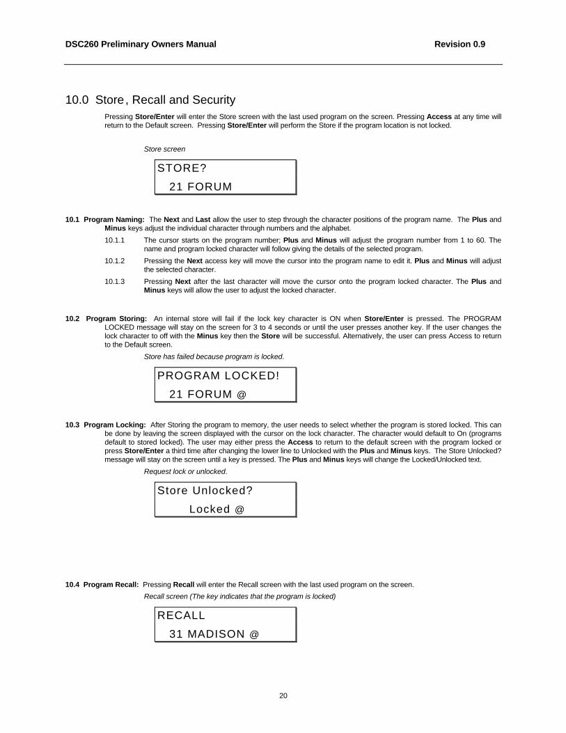
10.0 Store, Recall and SecurityPressing Store/Enter will enter the Store screen with the last used program on the screen. Pressing Access at any time willreturn to the Default screen. Pressing Store/Enter will perform the Store if the program location is not locked.
Store screen
STORE?
21 FORUM
10.1 Program Naming: The Next and Last allow the user to step through the character positions of the program name. The Plus andMinus keys adjust the individual character through numbers and the alphabet.
10.1.1 The cursor starts on the program number; Plus and Minus will adjust the program number from 1 to 60. Thename and program locked character will follow giving the details of the selected program.
10.1.2 Pressing the Next access key will move the cursor into the program name to edit it. Plus and Minus will adjustthe selected character.
10.1.3 Pressing Next after the last character will move the cursor onto the program locked character. The Plus andMinus keys will allow the user to adjust the locked character.
10.2 Program Storing: An internal store will fail if the lock key character is ON when Store/Enter is pressed. The PROGRAMLOCKED message will stay on the screen for 3 to 4 seconds or until the user presses another key. If the user changes thelock character to off with the Minus key then the Store will be successful. Alternatively, the user can press Access to returnto the Default screen.
Store has failed because program is locked.
PROGRAM LOCKED!
21 FORUM @
10.3 Program Locking: After Storing the program to memory, the user needs to select whether the program is stored locked. This canbe done by leaving the screen displayed with the cursor on the lock character. The character would default to On (programsdefault to stored locked). The user may either press the Access to return to the default screen with the program locked orpress Store/Enter a third time after changing the lower line to Unlocked with the Plus and Minus keys. The Store Unlocked?message will stay on the screen until a key is pressed. The Plus and Minus keys will change the Locked/Unlocked text.
Request lock or unlocked.
Store Unlocked?
Locked @
10.4 Program Recall: Pressing Recall will enter the Recall screen with the last used program on the screen.
Recall screen (The key indicates that the program is locked)
RECALL
31 MADISON @

DSC260 Preliminary Owners Manual Revision 0.9
21
10.4.1 The Plus and Minus keys select the program to Recall.
10.4.2 Pressing Access at any time will return to the Default screen.
10.4.3 Pressing Recall a second time will recall the program.
10.5 Security Settings: There are two levels of security for the unit. These are used to protect the parameters or programs from beinginadvertently changed by unqualified users.
10.5.1 Lock Out in the Utilities area. With lock out ON, no variables can be adjusted except Lock Out and noprograms can be stored or recalled. This is the most basic security. Unless you know specifically to unlock theunit in the Utilities page, the unit will remain free from prying hands.
10.5.2 OEM Lock in the Utilities area. OEM lock allows the user to lock any or all of the variables in a single programfrom being seen or adjusted. These locks are stored with the program and are transferred as files are stored andrecalled.
OEM lock screen.
LOCK UTILITIES
OEM Lock Off
10.5.3 Pressing Plus from the Utility screen enters the OEM password screen. The user enters a password by usingthe Next and Last keys to select the letters and the Plus and Minus keys to change the letters. PressingStore/Enter enters the OEM Lock mode. As an example, a password of “KONA” is shown below. Note: TheFactory default programs in locations 1, 2 and 3 come with no OEM password. These can be used to create yourown OEM programs.
OEM Password screen.
OEM PASSWORD
KONA____
10.5.4 Once in the OEM Lock set-up mode the user moves around the Input and Output screens as if selectingvariables to adjust. The utility screens are not accessible in Lock set-up, nor are the Store and Recall screens.
In the Lock set-up mode, the unit is always unlinked i.e. variables have to be locked/unlocked individually, theycannot be locked in stereo pairs. The user can see the variable names and values if they are not locked. If thevariable is unlocked, the current value is displayed. If the variable is locked the value is replaced with a key. Thetype of Lock Set-up - OEM - is indicated at the top right of the screen. The edited symbol is not displayed in theLock set-up mode.
10.5.5 Variables are locked and unlocked with the Plus and Minus keys.
Polarity on Output 5 - OEM unlocked - selecting variables for OEM lock
OUT 5 High OEM
Polarity
Polarity on Output 3 - OEM locked - User still in OEM Mode
OUT 3 Hi Mid
Polarity 3
The Lock set-up process is finished with the Store/Enter key. The unit now comes back to the password screenwith the current password on the screen. The user can change the password by using the Next and Last keys toselect the letters and the Plus and Minus keys to change the letters. Below the password “KONA” has beenchanged to “KIZ.” Pressing Store/Enter stores the new password and returns the user to the Utility menu.
OEM Password change screen.
NEW PASSWORD?

DSC260 Preliminary Owners Manual Revision 0.9
22
KIZ_____
10.5.6 Once the user has left OEM mode, the unit will not display any OEM locked variables. If the user steps on to anOEM locked variable the display will jump to the next unlocked variable. If all variables in a channel are OEMlocked the display will jump to the next channel.
10.5.7 If the unit is powered down while in OEM mode, the unit will return to OEM locked when the unit is turned backon with the current password still valid.
10.5.8 An OEM Locked program has a small padlock icon next to the program name when you scroll through using theStore and Recall Functions.
RECALL
31 MADISON ¢
Note: You cannot store a new program in an OEM locked location. You must delete the OEM locked program firstusing the Delete Program option in the Utility menu.

DSC260 Preliminary Owners Manual Revision 0.9
23
11.0 Techniques, Tricks and TrapsWhen developing a product such as the DSC260, you must balance how much flexibility is designed in versus theinevitable traps that might occur by having complete control over each outputs capability. The following section wasdesigned to give the user a bit of a head start when delving deeper into programming the unit.
11.1 Use Both Hands: When programming the unit it might be helpful to use a two hand technique. Using the right hand for navigationaround the programming grid and the left hand for adjusting the parameters. It helps remind the user that the right keys arefor navigation and the left are for changing parameters.
11.2 Oh, Where has my output gone? If you have a signal source assigned to an output, but do not have any output, check that theLow Pass Filter Frequency parameter has not been set to “Off”. If this has been adjusted upward beyond 16kHz, it will turnthe output off.
11.3 Delays in 1, 2, 3 Steps: When using Delay Linking, it is recommended that the adjustment order is: 1. Transducer alignment withincabinets; 2. Cabinet alignment within Clusters; 3. Delay Alignment between Clusters. In 2 channel x 3 Way and 3 channel x2 way, the default settings include delay linking as well as stereo linking. See section 5 for additional information.
11.4 Why do both Input Clip LEDs light without a +20dBu input: Situations can occur when both Input Clip LEDs light. If thisoccurs without full input signal, then this signifies a clip within the digital signal path. This normally occurs if excessive EQboost or gain has been programmed into one or more outputs.
11.5 I’m trying to adjust a crossover or EQ frequency but it won’t go as high or as low as I want. Check for any stereo linkedparameters that might contain an offset. If there is an offset between a stereo linked variable and the linked variable is at itslimit, then the parameter you are adjusting will not go any further. You can check this by turning Stereo Linking Off andlooking at the parameters in question. As an example, you could have a stereo EQ variable that is linked with a 5kHz offset sothat output 5 is at 10kHz and Output 6 is at 15kHz. If you try and adjust the EQ on output 5 upward, it will only go to 11kHz,not all the way to 16kHz. This is because as you adjust output 5 upward, output 6 also goes upward to a maximum of 16kHz.
11.6 I can’t get the delay to go to it’s maximum of 635 ms. As with example 11.5 above, linked parameters can cause confusionwhen they are linked with offsets. If a linked delay is at its maximum, trying to adjust another linked delay will stop at a valueof 635ms minus the amount of the offset. As an example, you have a delay link between output 3 (100ms) and output 5(200ms). If you try and adjust output 3 upward you will be able to get a maximum of 535ms. (635ms - 100ms = 535ms)
11.7 I don’t have any linked delays, but I can’t get the maximum 630ms on an input or output. The maximum delay is acombination of the amount of delay assigned at the input section plus the amount assigned at the output section. Themaximum combined delay from input to output is 635 ms.
11.8 “Warning, No More Filters” Even with the flexibility and full feature set of the DSC260, you could run out of DSP power at somestage. While the engineers and designers of this product have tried to squeeze out every last bit of power, in some cases youmight see the dreaded “Warning, No More Filters?” message. This indicates that there are no more filter sections available inthe DSPs. This can occur when trying to add more EQ, adding a crossover slope or increasing a crossover slope. Thismessage is most likely to occur when using 48dB/Octave slopes that eat up DSP power quickly. Check below for moreinformation.
11.9 The DSC260 has a Split Personality. There are two DSPs in the DSC260. Crossover and EQ filter assignments are split betweenthem. It is possible to use up all available EQ on the inputs and outputs 1 & 2 and still have EQ available on Outputs 3-6. Forpeople who like clever number puzzles, section 9.5 details these guidelines. For the rest of us, there is almost always enoughEQ to go around.
11.10 Start with the Bass: Because of the way DSP is allocated, it is recommended that the programming sequence is as follows:
AssignmentOrder
Parameters Reasoning
1 Output Crossovers 1 & 2 Use these for Low Frequency Outputs. They generally need the least amountof EQ and lower order crossover slopes. All EQ for outputs 1 & 2 and Inputscomes from DSP 1 only. Using less power hungry crossover slopes typical oflow frequency crossovers frees up EQ for Outputs 1 & 2 and inputs.

DSC260 Preliminary Owners Manual Revision 0.9
24
2 Output Crossovers 3-6 Use these for mid and high crossover outputs, because outputs 3-6 can useEQ power from both DSPs. These outputs are typically of higher slope andcan require more EQ.
3 Output 1 & 2 EQ As with the Output Crossovers, EQ on outputs 1 & 2 can only come from DSP1.
4 Output 3-6 By getting the outputs of 3-6 EQ’ed correctly, there will be little need for InputEQ.
5 Input EQ For touch up and taste with what’s left. If there is no more Input EQ available,adjustment of individual band EQ must be used or EQ must be “de-assigned”from outputs 1-2 to free up EQ for the inputs. Freeing up EQ on outputs 3-6will not free up resources for input EQ because the filters come from differentDSPs.
Table 3 Filter Assignment Recommendations
11.11 I’ve done it your way but I need more EQ on Inputs or Outputs 1 & 2: If you have maxed out EQ on the Inputs and Outputs 1& 2, but have spare filters in outputs 3-6, you need to get more power to the inputs. De-assign Output 1 & 2 EQ and put thepower into Input EQ. After you have the Input EQ assigned, go back and assign your Output 1 & 2 EQ. This time, theOutput 1 & 2 EQ will be taken from other resources.

DSC260 Preliminary Owners Manual Revision 0.9
25
12.0 SpecificationsInputs: 2 channels, Maximum level +20dBu, 10k≤ imp., Pin 2 +
Electronically BalancedOutputs: 6 channels, Maximum level +10dBu, into 600 ≤ imp., Pin 2 +
Electronically BalancedOutput Impedance: 47 ≤
Dynamic Range: >100 dBFrequency Response: 20Hz - 20kHz <+/- 0.5dB
Total Harmonic Distortion: <0.05%, 20 Hz - 20 kHz, @+10dBuConfiguration: Stereo 2 way and 3 way, Mono 4, 5, 6 way, Any combination of 2 inputs to six outputs with
individual passbands.Crossover Slopes: Butterworth 12, 18, 24 or 48dB/Octave and Linkwitz-Riley 12, 24 or 48dB/Octave.
Front Panel Controls: Softkeys for programming functions. Mute on each output and LED level meters with limit,-3, -6 and -20dB below threshold. Input LED meters with signal present, -12, -6 and-3dB and Clip.
Display: 2 x 16 Character Backlit LCDLimiters: Mid Band Limiters with variable threshold of -10 to +10dBu
Power Requirements: 100 - 240 Volts 50/60 Hz +/- 10%Sample Rate: 48 kHz
A/D Conversion:Assignable Equalization: An array of up to 38 bands of EQ can be assigned to the inputs and outputs. Dependent
upon slopes of crossovers used. High and Low shelving at 6dB or 12dB/Octave orfully parametric with a variable bandwidth of 0.05 to 3.0 octaves. Frequency rangefrom 15Hz to 16kHz. Amplitude of +/- 15dB in 0.5 dB steps.
Assignable Delay: Up to 635 ms of delay on each input to output path including Input A, Input B, Input A + BSum and Outputs 1-6.
Latency: 1.2 ms, any input to any output.Delay Resolution: 21 ms steps
Memory: 60 User Programs stored in Flash MemoryDimensions: 44.4mm x 483mm x 203mm HxWxD (1.75” x 19” x 8”)Net Weight: 2.8 kg (6.2 lbs)
Shipping Weight: 4.5 kg (9.9 lbs)Safety Agency Approvals: CE, ETL

DSC260 Preliminary Owners Manual Revision 0.9
26
Appendix A : Connector Wiring Information
Balanced wiring: Whether as system is wired to a ‘pin 3 hot’ convention is not so important so long as the wiring to both theinput and output are the same. Input cable shield needs to be derived from the signal source end as pin 1 is ground lifted forthe inputs. It is recommended that high quality audio cable with two conductors and a shield for low noise be used.
Unbalanced wiring: If the equipment driving the DSC260 has only unbalanced outputs then the input plug to the DSC260should be wired so that the shield connection on pin 1 is shorted to EITHER pin 2 OR pin 3, depending on the wiringconvention of the unbalanced equipment at the send end.
If the equipment connected to the DSC260 outputs has only unbalanced inputs, we recommend the use of balanced (i.e. 2-connector shielded) cable. The interconnecting cable should have the shield grounded to pin 1 at the DSC260 output, theoutput “cold” should be connected to the unbalanced input 0 V ground, and the output “hot” should be connected to theunbalanced live input. There should be no connection between the cable screen and the 0 V/chassis ground connection ofthe unbalanced equipment. Strict adherence to this will help to eliminate potential ground loop hums by removing signalcurrents from the cable shield.
Following the wiring conventions noted above within a fully balanced signal system will yield the best possible results withnone of the problems often associated with interconnected audio equipment. Wherever possible, the cable shield should notbe connected to any signal pin, but rather left to perform a cable shielding function only.
Under no circumstances should safety ground wire be removed from the AC power connector as an interim measure toachieve similar results.
Avoiding ground loops: A typical example of a ground loop situation is shown in the diagram below. Two interconnectedcomponents of a system are grounded through their individual AC power ground connections to separate AC power outlets.In this situation a path to ground exists both directly through the mains earth of each component and also via the shield in thesignal wire to the AC power ground connection of the other component. In effect the two paths to ground form a loop antennawhich picks up interference currents from surrounding equipment. Because of lead resistance these induced currents aretransformed into voltage fluctuations in the ground system and hence the reference ground is no longer at a stable potential.
Various connection configurations are possible to prevent ground loops occurring. The aim is always to ensure that a looppath is never actually formed. It can be seen from the diagram above that this could, in theory, be achieved by disconnectingthe AC power ground connection, however this practice is totally unsafe and should never be implemented as it could producea potentially lethal voltage at the case or accessible parts of the unit.
The most flexible solution, and easiest to implement in touring system, is to use the practice of telescoping shields. Thismethod is highly effective in removing ground loops and prevents unwanted signals entering the signal chain as the shield isalways connected to ground at only one point. The DSC260 is designed with the input ground connections isolated so that aground loop will not occur between the DSC260 and the preceding source component as shown below.

DSC260 Preliminary Owners Manual Revision 0.9
27
Appendix B : Output Assignment Matrix for JBL Systems
System Out 1 Out 2 Out 3 Out 4 Out 5 Out 6
2 Channel 2 Way Stereo Unused Unused Low A Low B High A High B
2 Channel 3 Way Stereo Low A Low B Mid A Mid B High A High B
Mono 6 Band Full A Full A Full A Full A Full A Full A
3 Channel 2 Way Config. Low A Low A+B Low B High A High A +B High B
4890, 4891, 4892, 4894,DMS-1
Unused Unused Low A Low B High A High B
4892+Subs, 4894+Subs,S201, S202, S203, S204,S205, S206, S210
Subs A Subs B Low A Low B High A High B
HLA 4895, AS32XX Stereo 3Way
Lo/Mid A Lo/Mid B Hi/Mid A Hi/Mid B High A High B
HLA Mono 4 Way, AS32XX 4Way
Unused Unused Subs A Lo/Mid A Mid/MidA High A
567X, 219X Low A Low B Mid A Mid B High A High B
1. Before making any connections between the controller and the amplifiers, make sure that all power to the amplifiers isdisconnected and their level controls are completely down.
2. The DSC260 has been programmed for many popular JBL Speaker System models. Before connecting the controllerto the amplifiers, this program should be changed to a setting that matches your JBL system.
3. This is done by powering on the DSC260 then pressing RECALL. Use the Parameter Plus and Minus buttons locatedon the left side of the LCD panel to page up and down until the correct setting is visible. Press RECALL after thecursor is on the setting.
4. Connect the console outputs to the inputs of the DSC260. Left to A and Right to B. In the case of a mono system, useinput A.
5. Connect the outputs of the controller to the amplifier input channels maintaining the Left and Right identification.Typically the higher the number of the output, the higher the frequency content. i.e. In a 2 channel 3 way default,outputs 1 & 2 are Low, 3 & 4 are Mid and 5 & 6 are high. As the outputs vary depending upon the type of systemand program loaded into the DSC260, consult Appendix B for correct output information.
6. Turn on the power to the console, controller(s) and finally the amplifiers. (It is best to turn the amplifiers on last and offfirst to prevent any thumps or pops from damaging the transducers.)
7. Apply a signal source to the controller. This can be pink noise, a tone or music.
8. Unmute the outputs on the DSC260, one at a time. The RED LEDs below each Output Meter signify the output ismuted.
9. Advance each amplifier channel slowly and confirm that the signal reaching the transducers is correct. (It is best tobegin with channels driving the low frequency transducers first. In this way, if the high and low are reversed, highfrequency signals will be going to the woofer. It’s better to find this problem then if the low frequencies were going tothe high frequency device!)
After it is confirmed that all transducers are receiving the proper signals, initial calibration can begin.

DSC260 Preliminary Owners Manual Revision 0.9
28
Limiter Settings for Power Levels into 4 ohms per channel
Power Amp 75 w 150 w 200 w 300 w 500 w 600 w 800 w 1200 w 2400 w
MPA 275 -4 dBu -1 dBu 0 dBu
MPA 400 -6 dBu -3 dBu -2 dBu 0 dBu
MPA 600 -8 dBu -5 dBu -4 dBu -2 dBu 0 dBu 1 dBu
MPA 750 -9 dBu -6 dBu -5 dBu -3 dBu -1 dBu 0 dBu
MPA 1100 -11 dBu -8 dBu -7 dBu -5 dBu -3 dBu -2 dBu -1 dBu 1 dBu
MPX 300 -4 dBu -1 dBu 0 dBu 2 dBu
MPX 600 -8 dBu -5 dBu -4 dBu -2 dBu 0 dBu 1 dBu
MPX 1200 -11 dBu -8 dBu -7 dBu -5 dBu -3 dBu -2 dBu -1 dBu 1 dBu
Limiter Settings for Power Levels into 8 ohms per channel
Power Amp 75 w 150 w 200 w 300 w 500 w 600 w 800 w 1200 w 2400 w
MPA 275 -4 dBu 2 dBu
MPA 400 -3 dBu 0 dBu 1 dBu
MPA 600 -5 dBu -2 dBu -1 dBu 1 dBu
MPA 750 -6 dBu -3 dBu -2 dBu 0 dBu 2 dBu
MPA 1100 -8 dBu -5 dBu -4 dBu -2 dBu 0 dBu 1 dBu 2 dBu
MPX 300 -1 dBu 2 dBu
MPX 600 -5 dBu -2 dBu -1 dBu 1 dBu 3 dBu
MPX 1200 -8 dBu -5 dBu -4 dBu -2 dBu 0 dBu 1 dBu 2 dBu
Bridge Mode Limiter Settings for Power Levels into 8 ohms
Power Amp 75 w 150 w 200 w 300 w 500 w 600 w 800 w 1200 w 2400 w
MPA 275 -7 dBu -4 dBu -3 dBu -1 dBu 1 dBu
MPA 400 -9 dBu -6 dBu -5 dBu -3 dBu -1 dBu 0 dBu 1 dBu
MPA 600 -11 dBu -8 dBu -7 dBu -5 dBu -3 dBu -2 dBu -1 dBu 1 dBu
MPA 750 -12 dBu -9 dBu -8 dBu -6 dBu -4 dBu -3 dBu -2 dBu 0 dBu
MPA 1100 -14 dBu -11 dBu -10 dBu -8 dBu -6 dBu -5 dBu -4 dBu -2 dBu 1 dBu
MPX 300 -7 dBu -4 dBu -3 dBu -1 dBu 1 dBu 2 dBu
MPX 600 -11 dBu -8 dBu -7 dBu -5 dBu -3 dBu -2 dBu -1 dBu 1 dBu
MPX 1200 -14 dBu -11 dBu -10 dBu -8 dBu -6 dBu -5 dBu -4 dBu -2 dBu 1 dBu

DSC260 Preliminary Owners Manual Revision 0.9
29
Appendix C: Midi Implementation
FUNCTION TRANSMITTED RECOGNIZED REMARKS
BASIC CHANNEL Default 1-16 1-16 Memorized
Changed 1-16 1-16
MODE X X
NOTE NUMBER X X
VELOCITY X X
AFTER TOUCH X X
PITCH BENDER X X
PROGRAM CHANGE 0-59 0-59
True Number 1-60 1-60
SYSTEM EXCLUSIVE
Dump Request X O
Dump Follows O O
Program Request X O
Program Follows O O
SYSTEM COMMON X X
SYSTEM REAL TIME X X
AUX MESSAGES X X
O: Yes X: No
DSC-260 Midi Sysex Format
The dump is sent as a series of system exclusive messages. The first message is a request to overwrite the memory ofthe DSC260.
Overwrite Memory Request
System exclusive status F0H Sysex Message Starts
Manufacturer ID 00H 20H 18H
Basic Channel nnH 0-15, or 7FH for all channels
Message Follows 06H
Message -Request Overwrite 03H
End of System Exclusive F7H

DSC260 Preliminary Owners Manual Revision 0.9
30
The second message is “Incoming dump, delete all programs?” If the Overwrite Memory Request is not accepted on thereceiving unit, this message will be ignored. The DSC260 deletes all programs from 1 up to 60 at this point, if the plug ispulled after this message, you can’t get them back!
Delete All Request
System exclusive status F0H Sysex Message Starts
Manufacturer ID 00H 20H 18H
Basic Channel nnH 0-15, or 7FH for all channels
Message Follows 06H
Message -Delete all, dump follows 0FH
End of System Exclusive F7H
The next message is the “system data”such as delay units, etc. Although the whole system structure is sent, only thedelay units are implanted as all the rest are the user’s choices, lock mode, midi channel etc. Bytes are sent with the low 4bits (nybble) followed by the top nybble. So Hex 0x74 is sent as 0x04 followed by 0x07. All values that follow are hexunless otherwise stated. Multiple byte values are sent with the highest byte first and the bytes split low nybble then highnybble.
System Dump Request
System exclusive status F0H Sysex Message Starts
Manufacturer ID 00H 20H 18H
Basic Channel nnH 0-15, or 7FH for all channels
DSC260 System follows 1CH
Size of message 03H Number of bytes divided by 32.
Program Number 00H Not used in this case.
Dump Data (96 bytes) ddH
End of System Exclusive F7H
Programs must be sent with the highest program numbers first. The DSC260 expects the last program to be program 0(the 'current' program). This is the data that is actually in use at the time and may not have been stored in one of the 60programs. Reception of the Delete All message (above) puts the unit into a 'sleep mode'. Reception of program 0 is thesignal for the unit to return to normal speed. Sleep mode while a dump is coming in is to ensure that all bytes are handledand that the flash erasing and programming can get the full time of the processor. If program 0 is not received the unit'ssleep mode will time out after about 20 seconds but during this period of the dump, the keys and display will not appearto be working. At the end of the time-out a message is displayed. If the unit is turned off during this time no data will belost as data is written as each program is received.
A single program dump can be sent at any time but be aware that sending a large number of new programs in quicksuccession while the unit is running at normal speed may cause midi bytes to be lost as there is not enough buffer spacefor full speed midi data during the one or two seconds it takes to erase a flash page.

DSC260 Preliminary Owners Manual Revision 0.9
31
Program Dump Message
System exclusive status F0H Sysex Message Starts
Manufacturer ID 00H 20H 18H
Basic Channel nnH 0-15, or 7FH for all channels
DSC260 System follows 1CH
Size of message 18H Number of bytes divided by 32.
Program Number ppH
Dump Data (426 -778 bytes) ddH Pairs of 4-bit nybbles, LS first. Sizedependent upon EQ assignments.
End of System Exclusive F7H

DSC260 Preliminary Owners Manual Revision 0.9
32
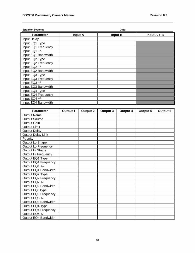
Appendix D: User Program TemplatesSpeaker System: Date:
Parameter Input A Input B Input A + BInput DelayInput EQ1 TypeInput EQ1 FrequencyInput EQ1 +/-Input EQ1 BandwidthInput EQ2 TypeInput EQ2 FrequencyInput EQ2 +/-Input EQ2 BandwidthInput EQ3 TypeInput EQ3 FrequencyInput EQ3 +/-Input EQ3 BandwidthInput EQ4 TypeInput EQ4 FrequencyInput EQ4 +/-Input EQ4 Bandwidth
Parameter Output 1 Output 2 Output 3 Output 4 Output 5 Output 6Output NameOutput SourceOutput GainOutput LimitOutput DelayOutput Delay LinkPolarityOutput Lo ShapeOutput Lo FrequencyOutput Hi ShapeOutput Hi FrequencyOutput EQ1 TypeOutput EQ1 FrequencyOutput EQ1 +/-Output EQ1 BandwidthOutput EQ2 TypeOutput EQ2 FrequencyOutput EQ2 +/-Output EQ2 BandwidthOutput EQ3TypeOutput EQ3 FrequencyOutput EQ3 +/-Output EQ3 BandwidthOutput EQ4 TypeOutput EQ4 FrequencyOutput EQ4 +/-Output EQ4 Bandwidth
Speaker System: Date:

DSC260 Preliminary Owners Manual Revision 0.9
33
Parameter Input A Input B Input A + BInput DelayInput EQ1 TypeInput EQ1 FrequencyInput EQ1 +/-Input EQ1 BandwidthInput EQ2 TypeInput EQ2 FrequencyInput EQ2 +/-Input EQ2 BandwidthInput EQ3 TypeInput EQ3 FrequencyInput EQ3 +/-Input EQ3 BandwidthInput EQ4 TypeInput EQ4 FrequencyInput EQ4 +/-Input EQ4 Bandwidth
Parameter Output 1 Output 2 Output 3 Output 4 Output 5 Output 6Output NameOutput SourceOutput GainOutput LimitOutput DelayOutput Delay LinkPolarityOutput Lo ShapeOutput Lo FrequencyOutput Hi ShapeOutput Hi FrequencyOutput EQ1 TypeOutput EQ1 FrequencyOutput EQ1 +/-Output EQ1 BandwidthOutput EQ2 TypeOutput EQ2 FrequencyOutput EQ2 +/-Output EQ2 BandwidthOutput EQ3TypeOutput EQ3 FrequencyOutput EQ3 +/-Output EQ3 BandwidthOutput EQ4 TypeOutput EQ4 FrequencyOutput EQ4 +/-Output EQ4 Bandwidth
DSC260 Preliminary Owners Manual Revision 0.9
34
Speaker System: Date:
Parameter Input A Input B Input A + BInput DelayInput EQ1 TypeInput EQ1 FrequencyInput EQ1 +/-Input EQ1 BandwidthInput EQ2 TypeInput EQ2 FrequencyInput EQ2 +/-Input EQ2 BandwidthInput EQ3 TypeInput EQ3 FrequencyInput EQ3 +/-Input EQ3 BandwidthInput EQ4 TypeInput EQ4 FrequencyInput EQ4 +/-Input EQ4 Bandwidth
Parameter Output 1 Output 2 Output 3 Output 4 Output 5 Output 6Output NameOutput SourceOutput GainOutput LimitOutput DelayOutput Delay LinkPolarityOutput Lo ShapeOutput Lo FrequencyOutput Hi ShapeOutput Hi FrequencyOutput EQ1 TypeOutput EQ1 FrequencyOutput EQ1 +/-Output EQ1 BandwidthOutput EQ2 TypeOutput EQ2 FrequencyOutput EQ2 +/-Output EQ2 BandwidthOutput EQ3TypeOutput EQ3 FrequencyOutput EQ3 +/-Output EQ3 BandwidthOutput EQ4 TypeOutput EQ4 FrequencyOutput EQ4 +/-Output EQ4 Bandwidth

DSC260 Preliminary Owners Manual Revision 0.9
35

DSC260 Preliminary Owners Manual Revision 0.9
36