dspace - national institute of technology,...
TRANSCRIPT

http://dspace.nitrkl.ac.in/dspace

Processing of MgO-MgAl2O4 Ceramics
and Study of its Microstructure,
Strength and Thermal Shock resistance
A THESIS SUBMITTED TO NATIONAL INSTITUTE OF TECHNOLOGY, ROURKELA
FOR THE AWARD OF DEGREE
OF
MASTER OF TECHNOLOGY (Research)
IN
CERAMIC ENGINEERING
BY
Deepak Mohapatra
UNDER THE GUIDANCE OF
Dr. D. Sarkar
DEPARTMENT OF CERAMIC ENGINEERING NATIONAL INSTITUTE OF TECHNOLOGY
ROURKELA – 769 008, ORISSA (INDIA) 2006

Department of Ceramic Engineering
NATIONAL INSTITUTE OF TECHNOLOGY
ROURKELA – 769 008, Orissa (INDIA) Dr.Debasish Sarkar B.Sc.(Chem. Hons) & B.Tech. (Ceramics) M.Tech.(IIT Kanpur) & Ph.D. (N.I.T, Rourkela) Sr. Lecturer
C E R T I F I C A T E
This is to certify that the thesis on “Processing of MgO-MgAl2O4 Ceramics and
Study of its Microstructure, Strength and Thermal Shock Resistance” submitted by Deepak
Mohapatra to the National Institute of Technology, Rourkela in partial fulfillment of the
requirements for the award of the degree of Master Of Technology (Research) in Ceramic
Engineering is a record of bonafide research work carried out by him under my supervision
and guidance. His thesis, in my opinion, is worthy of consideration for the award of degree
of Master Of Technology (Research) in accordance with the regulations of the institute.
The results embodied in this thesis have not been submitted to any other university or
institute for the award of a Degree or Diploma.
(D.Sarkar)
Tel: + 91 661 2462207 (O), 2463207 (R) Cell: 09437351756 Fax: + 91 661 247 2926/246 2999 Email: [email protected] /[email protected]
i

Acknowledgement
At the onset, I would like to express my heartfelt thanks and deep sense of gratitude to
my reverent teacher and honorable research supervisor Dr.D. Sarkar, for introducing me to
this vast field of Spinel, for his constant encouragement, efficient planning, constructive
criticism and valuable guidance during the entire course of my work. I thank you Sir for your
help, inspiration and blessings.
I express my heartfelt thanks to Prof. S. K. Sarangi, Director, NIT Rourkela for
providing the facilities to carry out this investigation. I would also express my sincere thanks
to Prof. S. Bhattacharyya, Head, Department of Ceramic Engineering, N.I.T, Rourkela for his
advice and constructive suggestion for the improvement of my work.
I would also take this opportunity to express my gratitude and sincere thanks to my
honorable teachers Prof. S. Adak, Ex-Head, Department of Ceramic Engineering NIT,
Rourkela, Dr. S. K. Pratihar and Dr. J. Bera for their invaluable advice, constant help,
encouragement, inspiration and blessings.
Submitting this thesis would have been a Herculean job, without the constant help,
encouragement, support and suggestions from my friends, especially R. P. Rana and Y. Nayak
for their time to help. Although it will be difficult to record my appreciation to each and every
one of them in this small space; I will feel guilty if I miss the opportunity to thank
Debasish Mohapatra, D. K. Dash, Bandana Raut and others. I will relish your memories for
years to come.
I would also express my sincere thanks to lab. members of Department of Ceramic
Engineering, N.I.T., Rourkela, especially P. K. Mohanty for constant practical assistance and
help whenever required.
My parents have always been a source of inspiration to me during the difficult times
without which it would not have been possible to complete this work. I would like to thank
Dr. S. J. Cho of Korea Research Institute of Science and Standards (KRISS), South Korea, for
help in microstructure analysis.
Above all, I thank Almighty for giving me all these people to help and encourage me,
and for the skills and opportunity to complete this thesis.
(DEEPAK MOHAPATRA)
ii

P R E F A C E
Chapter – I introduces the topic and background of the existing field.
Chapter – II deals with detailed literature review. Attempts have been made to
systematically classify the available information under different sections. This chapter
incorporates background information to assist in understanding the aims and results
of this investigation, and also reviews recent reports by other investigators with which
these results can be compared. The review finds unresolved questions in the
literature that can’t be answered by a single research work. The end of Chapter – II deals with the objectives of the present investigation. Chapter – III deals with the
detailed experimental processes related to this research work. Chapter – IV deals
with the results and discussion systematically with respect to powder processing,
characterization, densification study and evaluation of mechanical properties.
Chapter – V summarizes the conclusions, whereas, Chapter – VI illustrates the
possibility of Future Works.
A complete list of references has been given towards the end of the thesis.
iii

Certificate……………………………
Acknowledgment……………………
Preface………………………………
Table of Content……………………
List of Figures………………………
List of Tables………………………
Abstract………………………………
1.0. Introduction…………………
2.0. Literature Review……………
2.1. Starting Materials………
2.1.1. Alumina- Origin a
2.1.2. Magnesia- Origin
2.2. A common feature of Re
2.3. Classification of Spinel……
2.3 (a) Spinel……………
2.3 (b) Spinel Structure
2.3 (c) Normal and Inve
2.3 (d) Importance of M
2.4. Phase diagram of MgO-Al2O2.5. Reaction Mechanisms in Sp2.6. Properties of MgAl2O4 ………
2.7. Application Areas……………
2.8. Synthesis and Properties o2.9. Processing parameters and2.10. Objective............................
3.0. Experimental Procedure……
3.1. Experimental Apparatus
3.2. Chemical Analysis of Ra
3.2.1. Determination of
3.2.2. Determination of
3.2.3. Determination of
3.2.4. Determination of
3.3. Processing of Precursor
3.3.1. Milling……………
3.3.2. Drying……………
3.4. Particle Size Analysis…
Table of Content
…..........................................................................
……………………………………...........................
………………………………………………………..
………………………………………………………...
………………………………………………………...
………………………………………………………....
………………………………………………………..
…………………………………………......................
..…………………………………………………….... ………………………………………………………….
nd Crystal Structure of α-Alumina………………….
and Crystal Structure……………………………….. fractory material……………………………………...
………………………………………………………….
………………………………………………………..
………………………………………………………….
rse Spinel……………………………………………..
agnesium Aluminate Spinel…………………………
3……………………………………………………….
inel Formation………………………………………
……………………………………………………….
………………………………………………………..
f Spinel Composites………………………………..
properties at a glance……………………………. ................................................................................
………………………………………………………..
…………………………………………………………
w Materials…………………………………………… Silica…………………………………………………..
Mixed oxide (Fe2O3 and Al2O3)……………………..
MgO……………………………………………………
CaO…………………………………………………….
………………………………………………………….
…………………………………………………………
…………………………………………………………
………………………………………………………….
Page No.
i
ii
iii
iv
vii
ix
x
1
4
4
4
6
9
10
11
11
13
13
14
15
15
16
16
21
25
26
26
27
27
27
28
29
29
29
30
31
iv

3.5. Surface Area Analysis…………………………………………………………...
3.6. Calcination of Processed Powders……………………………………………..
3.7. Phase Analysis of calcined powders…..……………………………………….
3.7.1. Determination of Crystallite Size………………………………………..
3.7.2. Lattice Parameter Calculation…………………………………………...
3.7.3. Determination of % MgAl2O4 formation………………………………...
3.8. Densification………………………………………………………………………
3.8.1. Binder Addition……………………………………………………………
3.8.2. Pressing of Green Specimens………………………………………….
3.8.3. Dilatometry study of Pressed Specimens……………………………..
3.8.4. Sintering of Specimen……………………………………………………
3.9. Study of Bulk Density and Apparent Porosity…………………………………
3.10. Phase Analysis of Sintered Specimens………………………………………
3.11. Sample preparation for Microscopy analysis………………………………...
3.11.1. Polishing of sintered specimen………………………………………...
3.11.2. Thermal Etching of Polished specimens……………………………...
3.12. SEM analysis……………………………………………………………………
3.13. Mechanical Properties analysis……………………………………………….
3.13.1. Hardness measurement………………………………………………..
3.13.2. Diametrical Compressive Strength/ Brazilian Disk test analysis…..
3.13.3. Flexural Strength at Ambient temperature……………………………
3.13.4. Thermal Spalling………………………………………………………...
4.0. Results and Discussions…………………………………………………………….
4.1. Powder Preparation …………………………………………………………….
4.1.1. Chemical Analysis………………………………………………………..
4.1.2. Particle Size Analysis and XRD of milled powder…………………….
4.1.3. Phase Analysis of Calcined Powders………………………………….
4.1.4. Surface Area Analysis……………………………………………………
4.1.5. Compaction Behavior……………………………………………………
4.2. Densification and Microstructure……………………………………………….
4.2.1. Densification Study without Isothermal Treatment…………………..
4.2.2.Sintering…………………………………………………………………..
4.2.3. Phase Analysis of sintered specimens…………………………………
4.2.4. Bulk Density and Apparent Porosity……………………………………
4.2.5. Microstructure…………………………………………………………….
4.3. Mechanical and Thermal Properties…………………………………………….
4.3.1. Hardness………………………………………………………………….
4.3.2. Diametrical Compression Test / Brazilian Disk Test…………………
Page No.
31
32
33
35
35
36
36
36
37
37
38
39
39
40
40
40
40
42
42
44
46
46
48
48
48
49
50
55
55
57
57
58
60
64
67
71
71
73
v

4.3.3. Flexural Strength…………………………………………………………...
4.3.3. Thermal Shock Resistance………………………………………………..
5.0. Conclusions……………………………………………………………………………. 5.1. Powder Processing and Characterization………………………………………
5.2. XRD Analysis of Calcined powders……………………………………………..
5.3. Densification Study………………………………………………………………..
5.4. Phase and Microstructure Analysis……………………………………………..
5.5. Characterization of Mechanical Properties…………………………………….
6.0. Scopes for Future Works……………………………………………………………. References…………………………………………………………………………………..
75
77
79
79
79
80
81
81
83
84
vi

Fig.2.1. Basal plane of α-Al2O3 sho(large open circles) and the cations(small filled circles); small open circsublattice in α-Al2O3 filled circles ar(b)……………………………………… Fig.2.2. Crystal Structure of Magne Fig.2.3. Methodology of production Fig.2.4. Structure of MgAl2O4 ……… Fig.2.5. Phase diagram of MgAl2O4 Fig.2.6. SEM photomicrograph of M Fig.2.7. SEM photomicrograph of A Fig.2.8. SEM micrographs of sinterAlumina b) Sintered Magnesia-Alu Fig.2.9. a) XRD and (b) Raman spe Fig.2.10. SEM micrograph of a 20%and linked microcracks between thespinel)………………………………… Fig.3.1. Flow sheet of MgAl2O4 pow Fig.3.2. Flow sheet of Densification Fig.3.3. High Temperature Dilatome Fig.3.4. Temperature Profile during Fig.3.5. Layout of Scanning Electro Fig.3.6. Vickers’s Hardness tester… Fig.3.7. Arrangement for Brazilian D Fig.4.1. Particle Size Analysis after Fig.4.2. Average Particle Size with Fig.4.3. (a) XRD of Al2O3: xMgO po1.3, 1.4…………………………………
Fig.4.3. (b) XRD of Al2O3: xMgO po1.3, 1.4………………………………… Fig.4.3. (c) XRD of Al2O3: xMgO po1.3, 1.4………………………………… Fig.4.3. (d) XRD of Al2O3: xMgO po1.3, 1.4…………………………………
List of Figures
wing the hexagonal close packed anion sublattice occupying two-thirds of the octahedral interstices les are empty octahedral interstices (a).The cation e Al, open circles are empty octahedral interstices ………………………………………………….…….
sia.……………………………………………………..
of Sea water magnesia……………………………..
……………………………………………………….
Spinel…………………………………………….......
gO-rich spinel…………………………………….....
l2O3-rich spinel……………………………………....
ed spinels synthesized from a) Caustic Magnesia -mina………………………………………..…………
ctroscopy exhibiting disorderness and orderness.
22 µm spinel A composite, showing crack length spinel particles (dark grey: MgO, light grey: ……………………………………………………..…
der processing from starting materials………..….
and Mechanical property characterization……....
ter DIL 402C (NETZSCH)…………………..……..
Sintering………………………………………..…….
n Microscope…………………………………..…….
……………………………………………………….
isk Test………………………………………..…….
(a) 20h milling, (b) 40h milling and (c) 60h milling
respect to milling time……………………………….
wders calcined at 1000oC/2h; where x=1, 1.1, 1.2, …………………………………………………..….
wders calcined at 1100oC/2h; where x=1, 1.1, 1.2, ………………………………………………..…….
wders calcined at 1000oC/2h; where x=1, 1.1, 1.2, ………………………………………………..…….
wders calcined at 1000oC/2h; where x=1, 1.1, 1.2, …………………………………………………..….
Page No.
5
7
8
12
14
18
18
19
20
21
30
33
38
38
41
43
45
49
50
51
52
52
53
vii

Fig.4.4. Crystallite Size with respect to Al2O3: xMgO (weight ratio; where x=1, 1.1, 1.2, 1.3, 1.4 at different calcination temperatures……………………………………………… Fig.4.5. Compaction behavior of powders MAP1 and MAP5 with Al2O3 : MgO = 1:1 and 1:1.4; calcined at 1000oC/2h…………………………………………………………… Fig.4.6. Dilatometric study of green bar specimen obtained from 1000oC/2h calcined powders for all compositions……………………………………………………..…………. Fig.4.7. Ternary diagram illustrating the types of sintering………………………..…….. Fig.4.8. (a) XRD of samples calcined at 1000oC/2h and sintered at 1600oC/4h…….... Fig.4.8. (b) XRD of samples calcined at 1100oC/2h (c) 1200oC/2h and sintered at 1600oC/4h………………………………………………………………………………..…… Fig.4.8. (d) XRD of samples calcined at 1300oC/2h and sintered at 1600oC/4h…….... Fig.4.9. Bulk Density of 1600oC/4h sintered compacts with respect to temperature….. Fig.4.10. Relative density of 1600oC/4h sintered samples calcined at various temperatures and sintered at 1600oC………………………………………………………. Fig.4.11. Apparent Porosity of 1600oC/4h sintered compacts with respect to temperature……………………………………………………………………………..……. Fig.4.12. Microstructure of MAP1 powder calcined at 1000oC & sintered at 1600oC/4h. Fig.4.13. Microstructure of MAP1 powder calcined at 1300oC & sintered at 1600oC/4h. Fig.4.14. Microstructure of MAP5 powder calcined at 1000oC & sintered at 1600oC/4h. Fig 4.15. Microstructure of MAP5 powder calcined at 1300oC & sintered at 1600oC/4h. Fig.4.16: Hardness of various sintered specimen w.r.t increasing spinel content…..… Fig.4.17. Composite Hardness of specimens at different loadings w.r.t Al2O3 : MgO.. Fig.4.18. Optical Image of indentation shape of MAS1 (Al2O3 : MgO =1:1) at load of 98N………………………………………………………………………………………….…. Fig.4.19.Compressive Strength (σcomp) of MAS1 and MAS5 as a function of temperature. The sintering was carried out at 1600oC/4h……………………………..… Fig.4.20. Flexural Strength of sintered specimens from 3pt. bend test with respect to Al2O3: xMgO (where x= 1, 1.1, 1.2, 1.3, 1.4)………………………………………..…….. Fig.4.21. Schematic of (a) crack opening in tension but (b) closing in compression..… Fig.4.22. Retained Strength in samples after Thermal Spalling of 3 cycles at 800oC… Fig.4.23. Retained Strength in samples calcined at various temperature, after Thermal Spalling of 3 cycles Fig.4.24. SEM micrograph of fractured surface showing intergranular fracture MAS5 (1:1.4)…………………………………………………………………………………………..
Page No.
54
56
58
59
61
62
63
65
66
67
89
68
69
69
72
72
73
74
75
76
77
78
78
viii

Table 2.1. Properties attained with im Table 3.1. Summary of machineries Table 4.1. Chemical analysis of Star Table 4.2. Average Crystallite size acalcination of mixed powders at diffe Table 4.3. The calculated volume %from mixture of Al2O3 : xMgO (where Table 4.4. Surface area and particlearea analyzer………………………… Table 4.5. Surface area and particlesurface area analyzer………………… Table 4.6. Nomenclature given to ca Table 4.7. Spinel and MgO phase affrom calcined powders……………… Table 4.8. Bulk Density of sintered csintered at 1600oC…………………… Table 4.9. Apparent Porosity of sinteand sintered at 1600oC………………
List of Tables
plementation of various processing routes…….
and their use in this research…………………….
ting Materials……………………………………….
nd Lattice parameter of spinel phase after rent temperatures………………………………….
of spinel content of calcined powders obtained , x = 1:1, 1:1.1, 1:1.2,1:1.3, 1:1.4 in wt%)……….
size analysis of milled samples from BET surface ………………………………………………………
size analysis of calcined samples from BET ……………………………………………………..
lcined and sintered batches………………………
ter sintering (1600oC/4h) of compacts obtained ………………………………………………………
ompacts calcined at various temperature and ………………………………………………………
red compacts calcined at various temperature ………………………………………………………
Page No.
22
26
48
53
54
55
56
57
62
64
67
ix

ABSTRACT
MgO rich spinel precursor containing Al2O3 : MgO in weight proportions of 1:1, 1:1.1,
1:1.2, 1:1.3, 1:1.4 is prepared by solid-state reaction route. The processed and calcined
powders are characterized by Particle Size analysis, X-ray diffraction analysis and
sintering behavior. The processed and calcined powder exhibits a bimodal distribution
because of the presence of partially agglomerate and unagglomerated particle. However,
the average particle size varies from 6.84µm to 3.48µm with increasing milling time. The
optimized milling time and subsequent particle size are found 60h and 3.48µm
respectively. In the calcined powder spinel phase evolution starts around 1000oC and
follows an increasing trend in crystallinity and spinelization with increasing temperature.
The crystallite size is 19nm for lowest calcination temperature and lowest content of MgO
and gradually increases with increasing temperature and maximum 33nm has been
detected for powder with highest MgO content at 1300oC for 2h. Initial calcination
temperature and spinel seeds affect the densification as well as the extent of spinelization
in the sintered bodies. The relative density after sintering at 1600oC for 4h varies between
96-98% for Al2O3 : MgO=1:1, whereas composition with highest MgO content exhibits
this variation within the range of 95-97%. Low spinel seeding calcined batches show
better densification. Microstructure reveals presence of non-uniform grains and inter-
granular pores at lower calcination temperature and substantial grain growth is observed
in higher calcination temperature. Random grain orientation and increased inter-granular
porosity is responsible to deteriorate the density of high content of MgO powder when
sintered after calcination at 1300oC. The mechanical properties of MgO rich spinel
composites containing preformed spinel are more strongly influenced than the in-situ
formed spinel composites by sintering temperature, volume fraction and particle size of
spinel. The hardness of the MgO rich spinel composites is ~13.5GPa, which continuously
decreases (13.7–12.1GPa) with the increase of spinel phase at sintered specimen. Higher
amount of seed addition has an adverse affect on the hardness of the composites due to
coarsening of the spinel grains and formation of subsequent porosity. The compressive
strength (147-107MPa) is affected by the thermal expansion mismatch between spinel and
x

MgO and the partial bonding between MgO and spinel grains. The large amount of in-situ
spinel seeding as a result of higher calcination temperature has a detrimental effect on
strength values. The flexural strength of sintered specimens at room temperature as well
as the retained strength of sintered specimens after 3cycles of thermal spalling has been
measured. Both the tests have been carried out in 3-pt. loading system. The flexural
strength is noted to be around ~137MPa for sintered specimen (with 70% spinel content)
and has been found to decrease with increasing MgO content. The improved resistance
(5-12% of original strength) to thermal shock in the ceramics is attributed to the the
presence of higher amount of MgAl2O4 spinel at higher calcination temperature and
microcrack network interlinking. The large thermal expansion coefficient difference
between MgO and spinel, leads to extensive microcracking in ceramic materials with loss
in strength values, when MgO content is higher.
xi

Chapter 1
1.0. INTRODUCTION
Since the age of early civilization till today’s space age, man’s stages of
development/evolution are associated with discovery, invention and development of new
materials. Today’s era boasts a storehouse of created means of improving the human condition
that is at once thrilling and overwhelming. Yet like the fabled red shoes or the sorcerer’s broom,
discovery and invention will never stop. The arsenal still continues to grow. Today, thousands of
new materials have come into use to revolutionize our lives. Development of new materials and
their processing is helping the growth of novel technology in every field from Biology to
Electronics to come into existence. In short it can be said that without materials there is no
engineering. Ceramics today form the strategic materials base for development of new and
advanced technology. Different spinel forms an interesting field in ceramics. The spinel is an
exclusive category for different engineering applications. Mag-Al spinel is an important
refractory material with its unique combination of desired properties.
Magnesium–Aluminum spinel (Mag–Al spinel) is an important advanced ceramic
material possessing useful mechanical properties and wide range of applications even up to very
high temperature. Magnesium aluminate spinel is an excellent refractory material for its high
melting point, superior strength at ambient and elevated temperatures, excellent resistance
against chemical attack and thermal spalling. These properties make it a superior refractory
material for applications in side-walls and the bottom of steel teeming ladles, burning and
transition zones of cement rotary kilns, etc.1,2 For such applications spinel is used as a major
component in an alumina rich or magnesia rich matrix, depending upon the environmental
conditions prevailing in the application zone. Hence, magnesia rich or alumina rich spinel
compositions are important from the application point of view.
The methods of fabrication of spinel refractory has been known since 19053 and the
phase diagram of MgO-Al2O3 binary system has been well established since 1916 but still spinel
did not get much of commercial success till mid eighties mainly due to complexity in process
parameters. Spinel formation from its constituent oxides (Al2O3 and MgO) is associated with 5-
7% volume expansion, which hinders the densification process and does not allow the material to
1

densify in the same firing schedule4. Hence a two-stage firing process was employed. The first
step was to complete the spinel formation by getting the precursors calcined at an intermediate
calcination temperature, and the second one to densify the formed spinel (1600o-1800oC). It is
reported that the formation of spinel from magnesia and alumina does not produce dense product
in a single stage firing, due to the volume expansion associated5. Hence the general practice is to
complete the spinellisation process first and then crushing, milling, reshaping and sintering the
spinel to achieve desired properties in the second-stage firing. Methods of preparing dense spinel
products have improved considerably with progress of time. Various authors/ researchers have
reported the preparation of spinel by different routes.
The limiting factors for spinel preparation are the requirements regarding purity of the
raw materials, their reactivity, intermediate calcination temperature, higher sintering temperature
etc. Earlier many synthesis routes for spinel preparation have been implemented such as co-
precipitation6, combustion synthesis7, plasma spray decomposition of organo-metallic
compounds in superficial fluids, freeze drying, hydrolysis of metal alkoxides etc. No doubt these
methods have their advantages. These wet chemical routes reduce the formation/crystallization
temperature of Mg-Al spinel to somewhat around 7000C. Even they help producing nano-
powders. And this high surface area to volume ratio of ceramic sol makes the powder
sinteractive and hence high sinterability at lower temperatures is obtained. But the real challenge
in synthesizing nano-structured powders using wet chemical routes is to control and engineer the
physical properties of the starting materials as they affect the properties of the final products. To
point out some disadvantages- in co-precipitation method usually Al/Mg- nitrate/ chloride salts
are used. Repeated washing is required to remove the anions, which may alter the stoichiometric
composition. Moreover, washing is a tedious and time consuming process. And regarding the
combustion synthesis and sol-gel process- they involve chemicals that are sensitive to
environment. Also, the reproducibility of the properties in the end products through these wet
chemical routes is somewhat difficult to attain. However from industrial point of view, cost
effective and less complicated techniques are required for large-scale application. In this context,
solid-state reaction route is still the conventional and most feasible route in bulk production.
However, the limitation is that it requires high calcination temperature and high sintering
temperature. But to counter that there are mineralizers such as AlF3, V2O5, Y2O3, NaCl, MgCl2
etc. which promotes spinel formation at reduced calcination temperature and densification.
Many schools have been studying on processing parameters and characterization of
spinel and its composites, both stoichiometric and non-stoichiometric8. Literature shows that
2

purer raw materials led to end products of better refractoriness and reactivity of starting materials
largely influences both spinellisation reaction and densification of the spinel9,10. In another work,
it has been reported that fineness of the precursors attained by milling also plays a significant
role in reactivity of starting materials. Generally oxide ceramics by themselves do not exhibit
properties suitable to be used in desirable application areas. However through multiphase
ceramic materials there is a possibility of developing microstructure through which the properties
can be tailor made to handle desirable service environment. Usually, MgO-rich spinel has been
found to have better density and grain morphology than Al2O3 rich spinel. In earlier works, it has
been reported that incorporation of spinel particles of specific amount and specific particle size
into magnesia refractories has led to enhancement of mechanical properties of MgO-spinel
refractories.
On the basis of the above findings and importance, the particular interest of this study
was to develop spinel as end products that are rich in magnesia through solid state reaction. The
purpose also was to develop such composites from the combination of sea water magnesia and
commercially available α-Al2O3 powders by mix-milling them in weight proportion of Al2O3 :
MgO (A : M = 1:1, 1:1.1, 1:1.2, 1:1.3, 1:1.4) through double-stage sintering process. By paying
close attention to the earlier research work, it is well understood that the crystallization behavior
and densification of MgO-rich spinel depend on the amount of initial MgO-phase content,
amount of spinel seed and/or temperature. However, the effects of in-situ spinel seed content
through solid-state reaction of MgO-rich MgAl2O4 spinel on crystallization and densification
behavior are limited. In the present work, a wide range of MgO-rich spinel has been prepared
from their constituent solid-oxides in weight proportion, through calcination at different
temperatures. Phase analysis and densification has been carried out of the sintered specimens.
The sintered MgO-rich spinels have been characterized and analyzed for the crystallization
behavior, extent of spinel phase development and microstructure. Finally an attempt has been
made to correlate the effect of spinel seed addition on the crystallization behavior,
microstructure, hardness, compressive strength and flexural strength of sintered specimens.
Additionally, the retained flexural strength of the thermally spalled samples has been carried out
and correlated with microstructure.
3

Chapter 2 2.0. LITERATURE REVIEW
The literature review is divided into four major sections. Section 2.1 to 2.5 provide background
information on the material, identify significance of the spinel group of minerals and specify the
projected material with a discussion of relative advantages and disadvantages of the highlighted
synthesis processes. Section 2.6 to 2.8 reviews the processing techniques and the corresponding
results and properties observed by other investigators. This chapter incorporates background
information to assist in understanding the aims and results of this investigation, and also reviews
recent reports by other investigators with which these results can be compared.
2.1. Starting Materials 2.1.1. Alumina- Origin and Crystal Structure of α-Alumina:
Alumina is considered as a typical representative in the group of structural ceramics.
These materials are usually intended to serve as structural parts subjected to mechanical loads at
high temperatures. The common feature of structural ceramics is good mechanical behavior
therefore, efforts in developing, fabricating, and optimizing these materials are concentrated
towards high strength. Generally the objective of development of high strength ceramics is
substitution of metallic materials in relevant regions. Certain examples of structural ceramics, in
addition to alumina, are some pure oxide ceramics such as yttria (Y2O3), titania (TiO2), zirconia
(ZrO2), magnesia (MgO); and alumina-magnesia spinel (MgAl2O4), as well as the two non-oxide
ceramics which are extensively used in gas turbine applications, silicon nitride (Si3N4) and
silicon carbide (SiC). Gitzen11 in his work on aluminum oxide ceramic technology has traced the
individual crystallographic phases of alumina. He has reported the presence of seven
crystallographic phases of calcined, water free alumina had been found. The structural
applications of aluminum oxides are limited almost entirely to the α–phase (α-Al2O3), also
called corundum or, in its single-crystalline form, sapphire. Brag and Brag in 1915 were next to
Gitzen, in determination of the crystallographic structure of corundum. In 1925 the first exact
4

attribution to the rhombohedral structure (“corundum structure”) was made by Pauling and
Hendricks. Further crystallographic studies were carried out by Winchell.12
The structure of aluminum oxide consists of close packed planes of the large oxygen ions
stacked in the sequence A-B-A-B, thus forming a hexagonal close packed array of anions. The
cations are placed on the octahedral sites of this basic array and form another type of close
packed planes which are inserted between the oxygen layers. To maintain charge neutrality, only
two thirds of the octahedral sites available are filled with cations. Fig. 2.1a illustrates the packing
of Al and O in the basal plane. Since the vacant octahedral sites also form a regular hexagonal
array, three different types of cation layers can be defined, depending on the position of the
vacant cation site within layer, which may be named as a, b and c, and which are stacked in the
sequence a-b-c-a-b-c. This gives the complete stacking sequence of anion and cation layers of
the form A-a-B-b-A-c-B-a-A-b-B-c-A. It is only reproduced after the sixth oxygen layer or after
the sequence a-b-c is repeated twice (Fig. 2.1b).
(a) (b)
Fig.2.1. Basal plane of α-Al2O3 showing the hexagonal close packed anion sublattice (large open circles) and the cations occupying two-thirds of the octahedral interstices (small filled circles); small open circles are empty octahedral interstices (a).The cation sublattice in α-Al2O3 filled circles are Al, open circles are empty octahedral interstices (b) 13
The unit cell of α-alumina defined in this way is called the crystallographic or structural
unit cell, in contrast to the morphological unit cell, where the cation sequence is repeated only
once and the height is half that of the structural cell. This important difference between the two
cells, which has given rise to some confusion in the literature dealing with crystallographic
5
indices of sapphire, was pointed out clearly by Kronberg14. The structure of α-Al2O3 results in
coordination number of 6 and 4 for the cation and the anion, respectively. The ionic radii for this
coordination are 0.053nm for Al3+ and 0.138nm for O2-. Lattice parameters a0 and c0 are 4.7589
and 12.991Å respectively.
2.1.2. Magnesia- Origin and Crystal Structure: Magnesia or magnesium oxide is an alkaline earth metal oxide. Magnesium is the eighth
most abundant element constituting about two per cent of the earth's crust and typically 0.12% of
seawater. The majority of magnesium oxide produced today is obtained from the calcination of
naturally occurring minerals, magnesite, MgCO3, being the most common. Other important
sources of magnesium oxide are seawater, underground deposits of brine and deep salt beds from
which magnesium hydroxide [Mg(OH)2] is processed. Both MgCO3 and Mg(OH)2 are converted
to MgO by calcination. The thermal treatment of the calcination process affects the surface area
and pore size and hence the reactivity of magnesium oxide formed. The source largely
determines the level and nature of impurities present in the calcined material. Caustic calcined
magnesia which is used in a wide range of industrial applications e.g. plastics, rubber, adhesives
and acid neutralisation is formed by calcining in the range 700 – 1000oC. By calcining in the
range 1000 – 1500oC the magnesium oxide is used where its lower chemical activity is required
e.g. fertilizer and animal feed. Dead-burned magnesia, which is produced in shaft and rotary
kilns at temperatures over 1500oC, has reduced chemical reactivity therefore is more suited to
refractory applications. Finally fused magnesia which is produced in an electric arc furnace from
caustic calcined magnesia at temperatures in excess of 2650oC is used for a variety of refractory
and electrical applications.15
Magnesia has a wide range of refractory applications with good refractoriness and
good corrosion resistance. Magnesia is widely used in the steel industry as a refractory brick
often impregnated with carbon (tar, pitch, graphite) to give optimum properties for corrosion
resistance in environments of basic slag, particularly in BOF furnaces or slag lines of treatment
ladles. Recently Magnesia bricks often in combination with spinel or chrome are also used in
ferroalloy, non-ferrous, glass and cement industries. Castables and sprayables based on
magnesia are widely used for basic refractory linings for steel transfer applications. The lime to
silica ratio present in the magnesia has a major influence on its properties. In the structure of
6

magnesia, the magnesium and oxygen ions (charged atoms) are arranged in a periodic lattice.
Each positive ion is surrounded by negative ions, and vice- versa.
Fig.2.2 Crystal structure of Magnesia
Fig.2.3 shows a flow sheet of preparation of Seawater Magnesia16. Sea water is rich in
MgO (2lb/100gal.) is reacted with an alkali source (normally CaO or dolime) to precipitate
Mg(OH)2. Generally, the limestone or dolomite quarried is crushed, washed, graded and calcined
in rotary kilns at 1400-1500oC to produce reaction lime or dolime. The lime is then slaked to a
fine powder in pan hydrators. The hydrated product is then made into a slurry to facilitate
handling and mixing with the sea water and is classified to remove impurities.
Sea water is first pretreated with small proportions of H2SO4 to remove the bicarbonates
which would otherwise increase the CaO content of final MgO. H2SO4 reacts with calcium
bicarbonate to give CO2 which is dissolved in wooden desorption tower. This treated sea water is
then pumped to agitated reaction vessels where it is mixed with the classified dolime/lime slurry
and Mg(OH)2 is precipitated as dilute solution.
The Mg(OH)2 is allowed to settle in large diameter shallow tanks. The settled Mg(OH)2 is
washed and filtrated with seawater and fresh water. Then the resultant is calcined at 1600oC to get sea
water magnesite.
7

H2 SO4 Pretreatment (Removal of excess bicarbonates)
Reaction Reaction Lime dolime
Fine
powder Removal of impurities
Reaction Vessels MgSo4 . MgCl2 + 2H2O + 2CaO CaSO4.Cacl2 + 2Mg(OH)2ppt MgSo4 . MgCl2 + 2H2O + 2 (CaO + MgO) 4Mg(OH)2ppt + CaSO4.Cacl2
Sea Water
Settling in large diameter shallow tanks
Washing with sea water & then fresh water
FILTRATION
Calcination at 16000c to give Sea Water Magnesite
CLASSIFIER
SLURRY
Calcination at1400 – 15000C
Slaking in Pan Hydrators
Crushing, washing, grading
Quarrying of limestone or
dolomite
Fig.2.3 Methodology of Production of Seawater Magnesia16
8

2.2 A common feature of Refractory material
What sets Homo sapiens apart is the ability to imagine and create. This work addresses
a small segment of that arsenal. Man’s progress till date, has been marked by lots of invention
and discovery. In an advanced society, virtually, every thing depends directly or indirectly,
somewhere in its background, on manufacturing processes conducted at high temperatures. That
goes for every thing we eat, drink, learn, use, wear, occupy or enjoy, for our work, our health and
security, our mobility, our comfort and leisure. The positive impact of high-temperature
processes on modern life is all pervasive. The hot manufacturing processes that comes into an
ordinary man’s mind, generally includes the making, shaping or treating of metals, ceramics
including glasses and cements, electronic materials, fuels, a host of organic and inorganic
chemical products, and more. Industrial refractories make these hot processes possible and
economical when metal containment cannot compete. Refractories are thus enablers or
facilitators of our productivity.17
Refractory means “hard to fuse”. Refractories are class of materials, which can withstand
high temperature, resist the action of corrosive environments and dust-laden currents of hot gases
etc18. The refractory materials can be classified on the basis of composition and applications as
follows:
A) Acid Refractories
These are the refractories that are attacked by basic slags and include:
(i) Alumino-Silicate Refractories
(ii) Silica Refractories
B) Basic Refractories
These are refractories that are attacked by acidic atmosphere and include:
(i) Magnesite Refractories
(ii) Dolomite Refractories
(iii) Chrome Magnesite and Magnesite-Chrome Refractories
C) Neutral Refractories
These are the materials that are attacked neither by acids nor by bases. Such materials are
also used to replace basic refractories where the corrosive action is strong.
(i) Various forms of Carbon
(ii) Alumina
9

(iii) Artificial Refractories- eg. Zirconium carbide, Titanium Carbide and Silicon
carbide etc.
(iv) Metals- eg. Iron, copper, nickel, molybdenum, platinum, tantalum, thorium,
tungsten, vanadium, osmium and zirconium.
D) Special Refractories
These include expensive materials, which are used for the construction of crucibles and
furnaces for experimental and other special purposes. eg. BeO, ThO2, ZrSiO4.
E) Insulating Refractories
These are the high porosity refractories having low thermal conductivity and high thermal
insulation properties suitable for minimizing heat losses and maximizing heat conservation in
the kilns and for furnaces.
F) Cermets
These are special refractories, which are a combination of a metal or an alloy and non-
metal such as an oxide, carbide, nitride, or boride. They have high strength and resistance to
high temperatures, which make them suitable for use in very special and more recent
applications like those in space vehicles, missiles and nuclear energy plants etc.
2.3 Classification of Spinel Spinel – A Mineral:
Spinel literally means a hard glassy mineral consisting of an oxide of magnesium and
aluminium. It is a mixed/ternary oxide whose properties range between that of MgO and Al2O3.
MgAl2O4 (Spinel) is the most stable compound of MgO.Al2O3 system19.
Some common examples of minerals of spinel group are:-
Chromite – Iron Chromium oxide is the most important ore of chromium and is an important
metal with a wide range of industrial uses. It is resistant to the altering affects of high
temperatures and pressures and is used as a refractory component in the bricks and linings of
blast furnace. It has isometric crystal system 4/m bar 3 2/m with opaque crystals. They exhibit a
specific gravity of 4.5-4.8 and a hardness of 5.5.
Franklinite- Zinc Iron Manganese Oxide has metallic luster with an isometric crystal system;
4/m bar 3 2/m. It has a specific gravity of 5-5.2 and a hardness of 6. The crystals are opaque.
10

Gahnite- Zinc Aluminium oxide is one of the rarer members of this group. Gahnite produces
crystals showing well-formed octahedrons which are generally translucent to almost opaque. The
crystal system is isometric; 4/m bar 3 2/m and specific gravity is 4.55-4.6 and hardness is 7.5-8
Mohs respectively.
Magnetite- Fe3O4 is a member of the spinel group which has the standard formula A(B)2O4. The
A and B represent usually different metal ions that occupy specific sites in the crystal structure.
In the case of magnetite, Fe3O4, the A metal is Fe+2 and the B metal is Fe+3; two different metal
ions in two specific sites. The crystal system is isometric and has hardness of 5.5 - 6.5 in Moh’s
scale and specific gravity of 5.1.
Minium- Pb3O4 is actually composed of two different valence states (b+2 and Pb+4. The two
different valences of lead occupy different locations in the spinel type structure. Minium is a
tetragonal (bar 4 2 m) mineral. The small sizes of the lead ions, no doubt, cause a distortion in
the spinel structure. The specific gravity is 8.9 - 9.2 and hardness in moh’s scale is 2.5 – 3.
2.3 (a) Spinel:
Natural spinels are common high temperature minerals in metamorphic rocks. Spinels might
be also present as non-metallic inclusions in steel. Spinel is one of the end members of spinel
group of minerals, which have general composition of AB2O4, where ‘A’ is a divalent atom such
as Mg2+, Fe2+, Mn2+, Zn2+, and ‘B’ is a trivalent atom such as Al3+, Fe3+.
2.3 (b) Spinel Structure:
The spinel minerals have the generic formula AB2O4, where A is a cation with +2 charge
and B is a cation with +3. The most common members include:
A B Formula Mineral
Mg Al MgAl2O4 Spinel
Fe+2 Fe+3 Fe+2O.Fe+32O3=Fe3O4 Magnetite
Fe+2 Cr FeCr2O4 Chromite
Spinels crystallize in the cubic space group Fd3m (2 2 7) with 8 tetrahedral ‘a’ sites and 16
octahedral ‘d’ sites20. The usual anions are oxygen and are located in the 32 ‘e’ sites arranged in
11

cubic closed packed layers. The cubic closed packed layers of anions alternate with cation layers.
The unit cell contains 8 molecules of AB2O4. The physical and chemical properties of spinel is
decided by ‘A’ and ‘B’ as well as by the distribution of these cations in the different
crystallographic sites21,22,23.
In the “normal spinel” structure, all the divalent cations are located on tetrahedral ‘a’
sites, while all trivalent cations are exclusively on octahedral ‘d’ sites. If we represent
tetrahedral sites by ( ) and octahedral sites by [ ] then “normal spinel” can be said to have a
formula of (A)[B]2O4. In the “inverse spinel” structure, half of the trivalent 24 ions are on the
tetrahedral ‘a’ sites and the divalent cations occupy together with the remaining half of the
trivalent ions octahedral ‘d’ sites. The formula for inverse spinel as represented in above would
be (B)[AB]O4. Further it can be said that the structures with intermediate cation distribution
exists between these two limiting cases. The formula of these structures with intermediate cation
distribution can be (A1-xBx) [B2-xAx]O4; where x is inversion parameter and 0≤ x ≤ 1.
Fig.2.4 Structure of MgAl2O4 Spinel
12

2.3(c) Normal and Inverse Spinels:
Since there are twice as many filled octahedra as tetrahedra, and the formula for spinel is
AB2O4, it is possible to fill all the octahedra with B (trivalent) atoms and the tetrahedra with A
(divalent) atoms. We can't reverse the roles of A and B and fill all the sites. If we were to try, we
could only fill half the octahedra with A, and the tetrahedra would only take up half the B atoms.
The remainder would fill the still-vacant octahedra. Such a structure is called an inverse spinel.
Spinel and chromite are normal spinels, magnetite is an inverse spinel25. In reality, most spinels
are somewhere between the two end states. In the “normal spinel” structure, all the divalent
cations are located on tetrahedral ‘a’ sites, while all trivalent cations are exclusively on
octahedral ‘d’ sites. If we represent tetrahedral sites by ( ) and octahedral sites by [ ] then
“normal spinel” can be said to have a formula of (A)[B]2O4. In the “inverse spinel” structure,
half of the trivalent ions are on the tetrahedral ‘a’ sites and the divalent cations occupy together
with the remaining half of the trivalent ions octahedral ‘d’ sites. The formula for inverse spinel
as represented in above would be (B)[AB]O426,27. Further it can be said that the structures with
intermediate cation distribution exists between these two limiting cases. The formula of these
structures with intermediate cation distribution can be (A1-xBx) [B2-xAx]O4; where x is inversion
parameter and 0≤ x ≤ 1.
2.3 (d) Importance of Magnesium Aluminate Spinel:
Magnesium Aluminate (MgAl2O4) spinel ceramic is of significant technological interest
for refractory and structural applications at elevated temperature due to its high melting point,
good mechanical strength and excellent chemical resistance. It is the only stable compound
present in MgO.Al2O3 system. Owing to its chemical compatibility with alumina, zirconia and
mullite spinel is an attractive matrix for ceramic matrix composites28. The major application
areas of spinel refractory are transition and burning zones of cement rotary kilns, sidewalls and
bottom of steel teeming ladles and checker work of glass tank furnace generators because they
are resistant to corrosion by slag. For such applications spinel is used as a major component in an
alumina rich or magnesia rich matrix, depending upon the environmental condition prevailing in
the application zone. Hence, magnesia rich or alumina rich spinel (non-stoichiometric)
compositions are important from the application point of view.
Spinel type compounds are used in electrochemical devices and batteries as energy
sources for portable telecommunication devices. Together with their application as transparent
13

semiconductors in solar cells and displays, and even in the field of biology in dentistry spinels
are very promising research objects in materials science.
2.4 Phase diagram of MgO-Al2O3
The concerned phase diagram is MgO-Al2O3 binary system. Here the end components are
MgO and Al2O3 having high melting temperature 2800oC and 2020oC.
Fig. 2.5 Phase diagram of MgAl2O4 spinel29
MgO and Al2O3 form spinel at equimolar proportion i.e. 50:50 molar composition. The
spinel hence formed is a eutectic compound showing congruent melting nature. Spinel has got
high melting point around 2135oC. The spinel divides the whole system into two independent
eutectic systems those are MgO-MgAl2O4 and MgAl2O4-Al2O3 as shown in the diagram. So if a
stoichiometric proportion of MgO and Al2O3 is taken, heated and cooled down slowly then at
eutectic point, it gets converted to pure spinel.
The MgO.Al2O3 system is of considerable interest to the refractories technologist because: -
- Firstly, because spinel MgO.Al2O3 is a refractory in its own right
- Second because it shows that no liquid is formed with any mixture of pure magnesia
and alumina at temperature below 1900oC
14

Chesters and Parmelee showed that the reaction between equimolecular amounts of magnesia
and alumina results in a substantial reaction-expansion15. This composition or one higher in
magnesia composition can be made to produce steel-tight basic linings.
2.5 Reaction Mechanism in Spinel Formation
Formation of spinel from its constituent oxides is a counter diffusion process of Mg+2 and
Al+3 ions30 and this solid-state reaction depends on large number of parameters. Solid-state
reaction between MgO and Al2O3 to form spinel occurs at the Al2O3-MgAl2O4 and the MgO-
MgAl2O4 interfaces. The reaction between these phases is governed by counter diffusion of the
Al3+ and Mg2+ ions through the rigid oxygen lattice or the spinel phase. Three Mg2+ ions diffuse
for every two Al3+ ions, which diffuse in the opposite direction. Three moles of spinel are formed
at the Al2O3-MgAl2O4 interface for every mole formed at the MgO-MgAl2O4 interface because
of ionic charges and stoichiometry31,32. This is illustrated by the following schematic section
through a growing MgAl2O4 layer, which is called as Jander solid-state reaction geometry.
2.6 Properties of MgAl2O4 Spinel exhibits following properties33
1) High melting point ~ 2135oC
2) Hardness of ~ 8 Mohs / 14GPa
3) Density ~ 3.58 g/cc
4) Young’s modulus ~190 GPa
5) Resistance to chemical attack
6) Low electrical loss
7) Chemical compatibility with Al2O3, ZrO2, Mullite
8) Thermal Conductivity ~ 15W/moK
9) Nonmagnetic
10) Luster is Vitreous
11) Thermal Expansion Coefficient of ~7.6x10⁻⁶/ 0C
15

2.7 Application Areas Certain application areas in which spinel finds technical importance are34:
(i) Refractory Applications-Transition and burning zones of cement rotary kilns.
Sidewalls and bottom of steel teeming ladles and checker work of glass tank furnace.
(ii) Electronic Applications-Humidity and Infrared Sensors.
(iii) Optical Devices-Transparent material for arc enclosing envelopes and windows for
pressure vessels and bullet-proof vehicles, furnace sight glass. Substrate of luminous
faceplate of CRT, polarimeter for LED, Watch crystals, Safety goggles, as components in
optical computer and high-speed printer, High-pressure arc lamp and lens, pressure vessel
sight glass, furnace sight glass.
(iv) Armour materials-Missile domes, submarine port & covering for a tank port
(v) Alkali metal vapour discharge devices
(vi) Ceramic ultra filtration membranes
(vii) Insulating material for fusion reactor core- Container for nuclear waste
(viii) Ceramics in dentistry
(ix) A valve flap, valve seat, a water-jet cutting flow-shaper, a nozzle for process fluids.
(x) Tribological applications
2.8 Synthesis and Properties of Spinel Composites
Methods of fabrication of spinel have been known since 1905 and phase diagram has
been known since 1916 but it took time to gain commercial success till 1980s due to its
complexity in process parameters: mainly the volume expansion of ~5-7% which occurs during
MgAl2O4 spinel formation from its constituents. Spinel formation from its constituent oxides is
associated with 5-7% volume expansion which hinders the densification process to take place in
the same firing4. Various workers studied the effect of raw materials reactivity on spinel
formation and densification. Formation of spinel from magnesia and alumina does not allow the
material to densify in a single stage firing. Hence the general practice is to complete the
spinellisation process first and then crushing, milling, reshaping and sintering the spinel to
achieve desired properties in the second firing. Therefore two-stage sintering process and a
number of relevant processing parameters have greatly influenced the cost of production. The
limiting factors for spinel preparation are the requirements regarding purity of the raw materials,
their reactivity, intermediate calcinations temperature, higher sintering temperature etc.
16

Many authors/researchers have employed various experimental methods to produce spinel. Many
authors achieved spinel formation at a temperature as low as 600oC. This section describes
various methods implemented by various authors to produce spinel.
Kainarskii et.al35 studied the stability of sintered spinel, spinel-corundum, and corundum
refractories with certain oxides, salts, alkalis and alkaline metals at 1500-1700oC. They found
that magnesia-spinel and spinel were least reactive while corundum was the most affected.
Spinel sintered refractory was best in corrosive atmosphere. Antonov et.al36 studied
refractoriness of periclase-spinel refractories prepared from pure (seawater) and ordinary
sources. They found refractories produced from pure sources better in refractoriness than those
from ordinary sources. They studied the effect of impurities on the refractoriness of the products.
Microstructure of the pure source product was compared with that of ordinary source products.
In another work of their’s Antonov et.al8 have emphasized on solid phase reaction for bulk
production. They have tried to determine the technological parameters of synthesis of magnesia-
alumina spinel from periclase and bauxite. A temperature of 1500oC was reported to be optimum
for spinel synthesis from the starting materials. Microstructure study showed that excess
magnesia retarded grain growth. The authors also studied the effect of additives on density,
degree of crystallization, coloration and refractive index of magnesia rich spinel. Kostic et.al10
studied densification of partially synthesized spinel mixtures with and without addition of
CaO/SiO2 mixture. The degree of densification was found to be proportional to the initial amount
of spinel phase in the mixture. CaO/SiO2 mixture enhances grain growth in each spinel
composition and also helps enhance the densification. Pasquier et.al37 studied the effect of
isostructural and non-isostructural spinel seeding on synthesis of MgAl2O4 through different
methods. TEM micrographs confirmed that spinel seeding led to difference in morphology of
powders among the various routes. They observed that isostructural spinel seeding led to a
decrease in crystallization temperature of MgAl2O4 due to nucleation and epitaxial growth
mechanism. Gusmano et.al38 studied mechanism of MgAl2O4 spinel formation from thermal
decomposition of Co-precipitated hydroxides of alumina and magnesia in different molar ratios.
They observed crystallization of spinel phase at a temperature as low as 400oC due to reaction
between η−Αl2O3 and Mg(OH)2. Ko and Chan39 observed that the spinel content had a positive
effect on the Hot Strength of alumina castables in the temperature range of 1000-1500oC. The
hot modulus of rupture of selected material increased with increasing content of spinel. Sarkar
et.al40 studied effect of compositional variation and fineness of precursors on the densification of
17

MgO-Al2O3 compacts. Densification was observed to be easier and better for magnesia rich
composition with 4h attritor milling; but difficult for alumina rich composition. They found that
MgO rich and Al2O3 rich spinel had periclase and corundum as secondary phase respectively.
Microstructure revealed well developed compacted structure for stoichiometric and MgO rich
composition. Wantae Kim et.al41 carried out planetary ball milling of amorphous Mg(OH)2 and
gibbsite for 120min. crystallization of spinel phase was observed at 780oC after 15mins of
grinding. The authors claim that grinding promotes aggregation which deflocculated into fine
particles after calcination. R. Sarkar et.al42 observed that TiO2 improved density of
stoichiometric and Al2O3 rich spinels sintered at 1550oC; but higher amount of additive had a
deteriorating effect due to grain growth, which is supported by the micrographs. The
roundedness in grain structure affected the strength properties. The authors reported that TiO2
addition did not had much effect on MgO rich spinels. Laurence et.al25 studied influence of
synthesis routes on MgAl2O4 spinel properties. They observed higher crystallinity, higher
incorporation of Al3+ in tetrahedral sites and better electrical properties in samples synthesized
from sulfate precursors than from calcination of oxide mixtures. The better properties was
explained by better homogeneity of sulfate mixture than oxides due to presence of liquid phase
between 160-650oC. Ganesh et.al43 prepared stoichiometric MgAl2O4 spinel with AlCl3 as
additive by conventional double-stage firing process. The authors reported that MgAl2O4 spinel
when incorporated into high alumina and chrome refractories improved their resistance to slag
penetration and thereby erosion. In their work, L. B. Kong et.al44 implemented high-energy ball
milling process to attain MgAl2O4 spinel phase.
Fig.2.6 SEM photomicrograph of MgO-rich spinel45 Fig.2.7 SEM photomicrograph of Al2O3-rich spinel45
The sintering of milled-mixed MgO and Al2O3 powders led to spinel formation at
900oC/2h. The density as well as the crystallinity of spinel phase was observed to increase with
18

higher sintering temperatures. Microstructure also revealed better density with temperature due
to high reactivity of the starting materials due to intensive grinding. Ritwik Sarkar et.al45 varied
the reactivity of alumina by calcination between 800-1600oC and studied its effect on the
densification of non-stoichiometric spinels.
With increase in calcination as well as sintering temperature, the authors observed a
beneficial effect on densification of alumina rich spinels but not for the magnesia rich spinels
due to coarsening effect. They observed higher grain size in micrographs of high alumina content
samples. In another work, Sarkar et.al46 studied densification behavior of MgO rich spinels on
the basis of alumina reactivity.
The increase in calcination temperature of alumina caused inertness and increased the
expansion behavior of the composition. The authors observed least/no effect of calcination of
alumina in sintered density due to reduced sinterability/inertness. Calcination of alumina and
variation in sintering temperature of spinel did not influence the phase content of sintered
products. At higher calcination as well as sintering temperature the authors reported a reduced
hot strength due to coarsening effect. Sarkar et.al47 also studied effect of various additive oxides
on the densification of presynthesized and reaction sintered spinels. They reported better density
in reaction sintered products. TiO2 and Cr2O3 showed beneficial effect on densification while
V2O5 and B2O3 had detrimental effects. Tripathi et.al48 reported in their seminal work that solid
oxide reaction sintering of spinel developed from sintered magnesia-alumina (SMA) had better
densification (89%RD) than when developed from caustic magnesia-alumina (CMA). The higher
surface area and lower crystallite size leads to higher densification ratio and thus higher
expansion and exaggerated grain growth retards the densification process.
Fig.2.8 SEM micrographs of sintere
a
d spinels48
: a) Caustic magnesia alumin b) Sintered m
b
agnesia alumina
19

S.K Behera et.al7 synthesized spinel by autoignition process using citric acid as fuel and metal
nitrates as oxidizers. The authors have reported crystallization of spinel around 650oC and
attained theoretical density at 1150oC/30min. The authors calculated activation energy required
for densification of their system and reported vacancy diffusion influences densification. In an
extension to this work Barpanda et.al49 reported disorderness of spinel phase at lower calcination
temperature which became obsolete at higher temperature. A combined effect of chemical
composition and associated exothermicity of the reaction has been studied. The disorderness-
orderness is confirmed by XRD and Raman spectroscopy analysis.
Fig.2.9 a) XRD and (b) Raman spectroscopy exhibiting disorderness and orderness49.
Jia Xiaolin et.al50,51 studied the effect of amount and size of spinel crystal seeds on the
sol-gel synthesis of MgAl2O4 spinel. In their work they worked on factors influencing the
MgAl2O4 synthesis and recommended 1% crystal seeds. Initial crystallization temperature was ~
600oC and fully crystallized spinel phase was reported at 700oC. In his work on stoichiometric
and non-stoichiometric spinels from co-melting method Zawrah52 reported well crystalline spinel
phase at 1000oC. The author reported that the crystallinity decreased with higher alumina content
due to the decrease of lattice parameter and grain sizes. The author observed greater than 98%TD
in stoichiometric spinel upon use of Fe2O3 as sintering aid.
Ghosh et.al53 studied the effect of spinel addition in MgO refractories. MgAl2O4 spinel
synthesized from solid-oxide reaction route was incorporated into magnesia refractory. A
gradual decrease in thermal expansion behavior was observed with increasing spinel content.
This is due to lower thermal expansion of spinel than magnesia. This work shows; incorporation
of spinel greatly improves the refractoriness under load, retained strength after thermal shock and
20

hot modulus of rupture characteristics for the periclase body. The authors optimized 20wt.%
spinel addition for better properties with 670kg/cm2 of Hot MOR at 1200oC, RUL of ~1680oC
and ~380kg/cm2 of retained strength after 5 cycles. Recently, Aksel et.al54-56 illustrated the
influence of varying the amounts of spinel with a similar median particle size, with different
distribution, on the mechanical properties and thermal shock performance of MgO–spinel
composites. Mechanical properties of composites decreased significantly with increasing spinel
content due to the thermal expansion mismatch that the bending strength of MgO-spinel
composite is ~160MPa, which had been prepared with the addition of 5wt% of spinel powder
and sintered at 1650oC through hot pressing method. The author also found that the 3-pt bending
strength (233±7 - 61±4 MPa) as well as the Young’s Modulus (268±30 - 80±5 GPa) decreased
uniformly with increasing additions of spinel, and with increasing spinel particle size. They
observed that microcracks and grain boundary separation at MgO-spinel interface and concluded
these defects caused failure on loading. The authors have studied in details about the crack
mechanism involved in enhancement of strength at room temperature and after thermal shock.
They observed that loss of strength and modulus was greater for larger spinel particles because
of the increased extent of local tensile stress field. The authors have also studied the thermal
shock parameters, fracture behavior before and after thermal shock and work of fracture and
fracture surface energy.
Fig.2.10 SEM micrograph54 of a 20% 22 µm spinel A composite, showing crack length and linked microcracks between the spinel particles (dark grey: MgO, light grey: spinel)
However, Simonov57 in his work observed the compressive strength of the preiclase and MgO-
spinel materials varied within the range of 25-80MPa with an open porosity of 12.6-18.3%.
Cunbing et.al58 carried out hardness test on transparent MgO.nAl2O3 spinel ceramics (n=1, 1.3,
21

1.5, 1.8) under load of 200 and 1000g and observed an increasing trend of hardness (9-12GPa)
for transparent spinel ceramics with increasing alumina content. But they observed a
discontinuous trend of flexural strength measurement for 1700oC hot pressed specimens with
highest strength of ~220MPa at n=1.3.
2.9 Processing parameters and Properties at a glance
The Table 2.1 below shows different processes implemented by various authors under
various processing conditions and the results they concluded upon after their research work
Table 2.1: Properties attained with implementation of various processing routes
Methods Raw Materials Processing Conditions Properties 6Combined Gelation-Precipitation
Al2(SO4)3.16H2O MgSO4.7H2O 0.5 mol/l solution mixed to give 1:1 molar ratio of Al2O3 : MgO. Gelation carried out by NH4OH addition
Dried gel calcined at 300-12000C/1h. Uniaxially pressed samples were heated @ 100C/min up to 1100-14750C/3h
Average particle size of calcined sample 0.2µm.Surface area of 8.5m2/gPhase development starts from 6000C. Crystalline phase at 10000C. 95% of densification.
7Autoignition of citrate-nitrate gel
Al(NO3)3.9H2O, Mg(NO3)2.6H2O, and citric acid. Citrate–Nitrate ratio of 1:1. Self-ignition of the gel-like mass yielded a black mass.
Black Ash calcined at 650-11000C/9h. & at 16000C for 4h. Granulated powders were uniaxially compacted at 300MPa into cylindrical pellets (12mm φ, 3mm high).Sintering carried out in range of 650-1300oC 30 mins & 2h.
Phase development starts from 6500C.Crystalline-ordered phase at 11000C above.Crystallite size ranged between 12nm-32nm. ~ TD achieved. Activation energy for densification calculated to 16.4 kcal/mol. Lattice constant 8.08A
52Co-Melting Method
Al(NO3)3.9H2O [A], and Mg(NO3)2.6H2O [M]
Mixing of precursors to give A/M=1,1.1, 1.2, 1.3, 1.4. Mixtures heated on hot plate at 2500C till melting; then air quenched. Resulting solids heated for 2h at 5000CCalcination done at 10000C.Fe2O3 used as sintering aids in different proportion
Crystalline Mg-Al peak obtained at 10000C. TG shows 20% wt.loss. Crystallinity decreased with higher Alumina % Crystal size obtained was between 12-59nm. Particle size obtained was between 10-60nm. Infrared spectroscopy showed bands of AlO6
groups building up
22

Methods Raw Materials Processing Conditions
Uniaxially pressed samples @ 60MPa sintered between 1450-16500C at 10oC/min.Infrared spectroscopy was done. Plastic hardness [PH] and [EM] Elastic modulus tests done for mechanical property study
Properties MgAl formation.>98% TD achievable Fe2O3 presence led to increase of sinterability after 16500C and improved mechanical properties;EM~280GPa and PH~15 GPa
44Mechanochemical Processing
Commercially available MgO and Al2O3.
Planetary ball milling at room temperature for 12h. in WC vial & WC balls as grinding media at 200 rpmUniaxially pressed compacts @ 50MPaSintered between 900- 15000C/2h at 100C/min
Milled mixture yields a grain size ~ 100-300nm Beyond sintering temp. of 11000C grain size increases to 0.5-1.5µm. ~96% TD achieved. ~98%TD with grain size of 2-5µm obtained at 15500C/2h
41Mechanochemical Processing Dry grinding
Al(OH)3 having mean particle size of 25.8µm and Mg(OH)2 of mean particle size 2.9µm
Stoichiometric composition was mixed using an agate mortar with pestle in acetone. Planetary ball milling at 790rpm was employed for grinding from 5 to 240 min. Calcination of ground mixture was done at 600-1200oC for 1h.
Crystalline Mg-Al phase from ground mixture was detected at 7800C after 15 min of grinding. Prolonged grinding promotes the aggregation of ground fine particles, but the aggregates deflocculate after calcination.
59Mechanochemical Processing
Mg(OH)2 [M] and Al(OH)3 [A]
M & A calcined jointly [R] (for spinel presynthesisation) as well as separately named [C]. M & A mixed in 1:1 molar ratio. Calcination @40C/min at 1400 and 16000C.Mixing of R & C done in Attritor mill for2,4,6h.Isostatic pressing of
Milling improves densification for both batches R and C. ~99.5% TD achieved for both batches after milling for 6h and sintering at 16500C.
Higher calcination temperature and longer milling produces better
densification. Deleterious effect of
23

Methods Raw Materials
Processing Conditions milled powders done at 175MPa. Sintering @10C/min at 1550,1600,16500C/2h
Properties spinellisation (due to expansion) has been avoided in the single stage firing process
60Microwave assisted Solid -State Reaction
Caustic MgO and Al(OH)3
Starting materials were mixed with Carbon black in 10-50wt.% Carbon containing raw mix was compacted to cylindrical rods (Φ25mm, 90mm high) @ 7.1MPa.Rods exposed to micro waves of 2.45GHz for 30-100 min.
Powder with >80% spinel content were produced in presence of 20wt.% C and >93% spinel content with 50wt.% C after 100min The process saves power and processing time, with good sintering characteristics in Properties terms of BD, AP etc.
40Solid State Reaction
Al2O3 and MgO Oxides mixed in molar ratio of MgO: Al2O3= 2:1, 1:1 and 1:2 were Attritor milled for 2, 4 and 6 hrs. Compaction by CIP @ 175 MPa (Φ25mm)Sintering @10C/min at 1550,1600, 16500C for 2h
High density was achievable in all three batches due to milling.MgO rich batch show ease of sintering. Al2O3 rich batch shows less sinterability but milling helps positivelyAttritor milling/4h is effective & economic.Spinel was major phase in sintered Al2O3 rich and stoichiometric batch implying solubility of excess Al2O3.
In present work effect of increasing variation of MgO is seen- in the resulting spinel formation,
crystallite size, densification behavior, and mechanical strength (Brazilian Disk Test), flexural
strength and thermal spalling; through Solid-State reaction method.
24

2.10 Objective of the thesis The extensive literature survey reveals that the synthesis of spinel powders through
various routes has been attempted by number of researchers. Simultaneously, attempts to
decrease the crystallization temperature of spinel phase, increase the densification by additives,
developing a better microstructure have been made. The thermo-mechanical properties of MgO-
spinel composites have been studied by spinel incorporation into MgO have been studied by
different researchers. However, the thermo-mechanical properties of spinel composites
developed from Al2O3 : xMgO (where x =1, 1.1, 1.2, 1.3, 1.4) in different weight proportions
through solid state reaction route has not yet been reported according to best my knowledge. The
intent of this work is to create substantial experimental database on the preparation, processing,
characterization and mechanical properties of the developed specimens- to observe the effect of
increasing variation of MgO in the resulting spinel formation, densification behavior, and
mechanical strength (Brazilian Disk Test) through solid-state reaction method. Subsequently, the
flexural strength at room temperature and the retained strength of thermally spalled specimens
were also carried out. The project was implemented in two stages. The first-stage involved the
powder processing and characterization. In the second-stage, the mechanical and thermo-
mechanical characterization by Brazilian Disk Test and three-point loading system.
Hence, objectives of the present investigation can be summarized as follows:
The objectives of this work include:
• To prepare spinel from different composition (i.e. with variation in Al2O3 : MgO) through
Solid state route.
• To analyze the phase formation with increasing calcination temperature by XRD
technique.
• To obtain dense MgAl2O4 by cold pressing and subsequent sintering at desired
temperature (16000C) in ambient atmosphere.
• To analyze the effect of initial calcination temperatures and subsequent spinel content on
densification of final products.
• To characterize the resultant material by XRD and SEM.
• To study different mechanical properties like: hardness, compressive strength, flexural
strength and retained strength after thermal spalling and correlate with microstructure as
well as spinel content in sintered specimens.
25

Chapter 3 3.0. EXPERIMENTAL PROCEDURE
3.1 Experimental Apparatus
During this research work, several equipments and engineering appliances were used.
The purpose and list of the equipments are listed in Table 3.1
Table 3.1 Summary of machineries and their use in this research
Equipment Purpose
Agate Mortar & Pestle For PVA mixing to calcined samples. Grinding and mixing of samples manually.
Automatic Grinding & Polishing Unit Buehler, Ecomet 3-Automet 3
For smooth and fast polishing of sintered specimen
Ball Mill For wet mixing of MgO and Al2O3 powders
Crucibles For powder calcination
Dilatometer (0-16000C)
NETZSCH DL 402C
To study densification and expansion behavior of pressed samples at different temperature
Dryer To dry out acetone from wet mixed powder
Electrical Resistance Muffle Furnace (17000C) BYSAKH & CO.
Calcination of milled samples and Sintering of pressed pellets
Electronic Balance Adair Dutt & Co.
Powder material, density were measured accurately
Glass Apparatus Conical flasks, glass rod, beaker, burette, pippete, funnels
For Chemical Analysis of starting materials by Acid- dissolution method
Hydraulic Press 10 T, SoilLab Testing Instruments
Pressing/forming of powdered samples into desired shapes
Instron Flexure Tester Model-Hounsfield H10KS, U.K
Mechanical strength testing-Diametrical Compressive strength, Three-point Flexural Strength
Particle Size Analyser Malvern Mastersizer/E, UK
Agglomerate size distribution analysis of milled samples
Scanning Electron Microscope JEOL JSM 840
Microstructural analysis of polished samples
Ultrasonic Bath Teksonics
Surface cleaning of specimens
Universal Diamond Cutting Tool Buehler, Isomet, Germany
To cut away a sample accurately at desired position
X-Ray Diffraction Phillips PW 1830, Holland
Quantitative and qualitative Phase Analysis
26

3.2 Chemical Analysis of Raw Materials
The starting raw materials were taken for chemical analysis by acid dissolution method to
determine the composition of constituents present in the as received powders.
(a) Sea water Magnesia
3.2.1. Determination of Silica:
In a pre-weighed platinum crucible 0.5 grams of properly ground fine MgO powder was
taken. To this 10 grams of Na2CO3 and few beads of NaOH were added. This mass was mixed
properly and was fused at 1000oC for 1 hour. The cooled fused mass was then dissolved in acid.
The fused mass was treated with 100 cc of 1:1 HCl acid in a beaker. The solution was then baked
overnight on a hot plate at a temperature of 40-50oC. Then 50 cc of 1:1 HCl was added to the
baked mass. The mass was then warmed and cooled. The resultant was then filtered through
Whatman 40 filter paper with simultaneous hot water washing. The filtrate was then collected in
a 250-ml. volumetric flask. This filtrate was marked as Filtrate 1. The residue was then taken in a
pre-weighed platinum crucible and fired at 1000oC for 1 hour. The residual after firing was
reported as Silica content in the sample taken.
The equation 1 was used to determine the Silica content in the sample: -
Taking weight of MgO sample as Ws
Final weight of crucible after firing the first filtration residue at 10000C/1h = Fw and
Initial weight of crucible without the filtration residue = Iw
Silica (in %) = 100×⎥⎦⎤
⎢⎣⎡ −
WsIwFw ----------------------------- (1)
3.2.2 Determination of Mixed oxide (Fe2O3 and Al2O3):
The volume of Filtrate 1 was made up to the mark. Then 50 cc of the made up volume of
the Filtrate1 was taken in a conical flask. A few drops of methyl red indicator was added to it
which turned the solution red. This was followed up by addition of AAC buffer till the color
turned yellowish. The resultant solution was then warmed. Then filtration was carried out using
Whatman 42 filter paper. The filtrate was collected in another 250-ml volumetric flask and
named as Filtrate2. The residual was then fired at 1150oC for 1 hour. The fired residue was
reported as mixed oxide.
27

The equation 2 was used to determine the mixed oxide content in the sample: -
Taking the weight of the MgO sample as Ws
Final weight of crucible after firing the first filtration residue at 1150oC/1h = Fw and
Initial weight of crucible without the filtration residue = Iw
Mixed oxide (in %) = 1005××⎥⎦⎤
⎢⎣⎡ −
WsIwFw --------------------------- (2)
To determine the Fe2O3 content -10 cc of the Filtrate 2 was taken in a conical flask. 10 cc of
NH4CN (Ammonium Thiocyanate) was added to it. This turned the solution blood red in color.
This resultant solution was then titrated against standard Mercurous nitrate solution with
vigorous shaking till colorless end point was attained. The amount of Hg(NO3) consumed gave
the iron oxide content present in the sample. The difference from mixed oxide was reported to be
Al2O3 content present in the sample.
Taking the weight of the MgO sample as Ws
Considering amount of Hg(NO3) consumed to be x
1ml. of 0.0015 M Hg(NO3) solution ≡ 1.197704 x 10⁻⁴ grams of Fe2O3
Fe2O3 content present in the sample was determined by the equation 3.
Fe2O3 (in %) = 1002510197704.1 4
××⎟⎟⎠
⎞⎜⎜⎝
⎛ ×× −
sWx -----------------------(3)
Al2O3 (in %) = Mixed oxide content - Fe2O3 content
3.2.3 Determination of MgO:
In a conical flask 10 ml aliquot of Filtrate 2 was taken and to it 10 ml of AAC buffer was
added. A pinch of Erichrome Black-T indicator was added to the solution, which resulted in wine
red color of the solution. This solution was then titrated against standard EDTA (Ethylene d-
ammine tetra acetate) solution (0.01M) till sky blue end point was attained. The volume of
EDTA consumed gives us the magnesia content of the sample.
1ml of 0.01 EDTA solution ≡ 4.031 x 10⁻⁴ grams of MgO
Taking amount of EDTA solution consumed to be y
And weight of the sample taken as Ws
28

The Magnesia content in the sample was determined by the given equation
MgO (in %) = 10025510031.4 4
×××⎟⎟⎠
⎞⎜⎜⎝
⎛ ×× −
sWy ---------------------- (4)
3.2.4 Determination of CaO:
The volume of the Filtrate 2 was made up in the volumetric flask. In a conical flask 10 ml
of Filtrate 2 was taken and to it 10 ml of NaOH (20%) was added. Then a pinch of P & R
indicator was added to the above solution, which resulted in a light violet color of the solution.
The resultant solution was then titrated against standard (0.01M) EDTA (Ethylene Di-Amine
Tetra Acetate) solution till a colorless end point reached. The amount of EDTA consumed gave
the CaO content in the sample.
1ml of 0.01 EDTA solution ≡ 5.608 x 10⁻⁴ grams of CaO
Taking amount of EDTA solution consumed to be z
And weight of the sample taken as Ws
The Calcium oxide content in the sample was determined by the under given equation
CaO (in %) = 10025510608.5 4
×××⎟⎟⎠
⎞⎜⎜⎝
⎛ ×× −
sWz ------------------------ (5)
(b) Commercially available Alumina
The same methodology as mentioned in the case of Sea water magnesia was employed to
determine various constituents present in taken amount of Alumina powder.
The chemical properties of the starting raw materials are given in Table 4.1
in Chapter 4.
3.3 Processing of Precursor 3.3.1. Milling:
Seawater Magnesia and commercially available Alumina were used as starting materials.
The starting materials were mixed according to weight proportions of (Al2O3 : xMgO where x is
1, 1.1, 1.2, 1.3, 1.4). The starting raw materials i.e. Magnesia and Alumina were taken in
different containers according to required weight proportion. The containers were numbered
according to the weight proportion, from 1 to 5 for distinction. Thus five different batches were
29

prepared. The weighed powders for each batch were mixed with acetone, and to each container
certain numbers of high dense ZrO2 balls were added to act as grinding media. The powder was
mixed with acetone as grinding aid to reduce the excess heat generation during grinding. The
ZrO2 balls were filled to the slurry up to 3/4th volume of the container. The powders were then
ball milled for 60 hours in presence of acetone with high dense ZrO2 balls as grinding media.
Fig. 3.1 represents the procedure followed for powder processing.
Fig
α-Al2O3 powder Seawater MgO
Milling at different schedule and optimized for 60h
Surface Area Analysis by BET method
Mixing-Ball Milling in weight proportion of Al2O3: MgO (A:M) =
1:1,1:1.1,1:1.2,1:1.3,1:1.4 with Acetone and high dense Zirconia balls as grinding media
3.3
of
ac
sa
Particle Size Analysisby Malvern Particle Size Analyzer
.3.1: Flow sheet of MgAl2O4 powder processing from starting materials.
Drying at 400C for 24h
Different batches of dried powder with A: xM, where x =1, 1.1, 1.2, 1.3 and 1.4 are designated as MAP1,
MAP2, MAP3, MAP4 and MAP5 respectively
.2. Drying:
After the milling process, each container was cleared of the milled contents. The contents
each container were poured onto different clean petridish. Each petridish was marked
cording to the number of the container to distinguish each sample composition. The milled
mples were subsequently dried in air for 24 hours to get rid of the acetone.
30

3.4 Particle Size Analysis
A laser diffraction method with a multiple scattering technique has been used to
determine the particle size distribution of the milled powder. To measure the particle size
through laser scattering method, the instrument detects the correlation between the intensity and
the angle of light scattered from a particle, and then calculates the particle size based on the Mie-
scattering theory. In order to capture scattered light signals over this range of angles, the
equipment utilizes a number of high-angle and back-scatter detectors, together with a short
wavelength blue LED laser. As the particle size becomes smaller, the scattered light signal shifts
to the side and rear with respect to the light source. Shorter wavelength detects the smaller
particle size. The scattered light can be measured by a series of photo detectors placed at
different angles. This is known as the diffraction pattern for the sample. As the instrument
measures clouds of particles rather than individual ones, it is known as an "ensemble" technique,
with the advantage that at smaller sizes (e.g. 1microns) the system is measuring literally millions
of particles which gives some statistical significance to the measured results. The particles size
distribution (volume percent) of the suspension was carried out in computer-controlled particle
size analyzer (Malvern, Mastersizer 2000, UK) via a software program. The powders must not be
agglomerated and completely dispersed in the liquid so that they are separated into discrete
unattached particles. Powdered samples used to be well dispersed in a liquid medium of known
density and viscosity. The milled samples were taken for particle size analysis after 20, 40 and
60 hours. Fig. 4.1 shows the particle size analysis of samples.
3.5 Surface Area Analysis
Specific surface area of ultrafine submicron ceramic powder is an important objective to
predict the green compaction and sintering characteristics. This can be measured by a common
BET method. The BET method (Brunauer, Emmet, Teller after the developers of the basic
calculations) involves adsorbing a monolayer of liquid nitrogen onto the surface of a mass of
particles, then measuring the amount of nitrogen that is released when that monolayer is
vaporized.
Specific surface area of milled as well as calcined powders was determined by BET
surface area analyzer (Quantachrome Instruments, U.S.A.). Surface area was determined as per
BET method. About 2-3gm sample was taken in the sample cell and degassed at 100oC in
vacuum up to a maximum of 3mbar. The sample holder mouth was closed by a stopcock. Sample
31
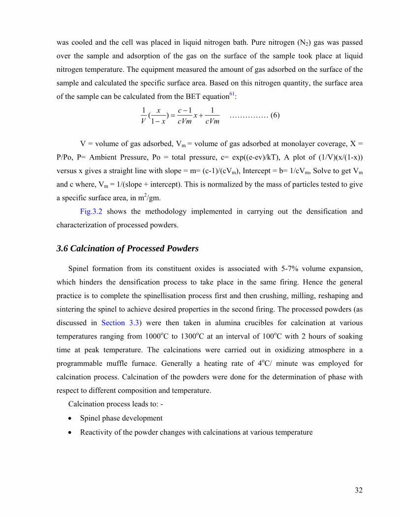
was cooled and the cell was placed in liquid nitrogen bath. Pure nitrogen (N2) gas was passed
over the sample and adsorption of the gas on the surface of the sample took place at liquid
nitrogen temperature. The equipment measured the amount of gas adsorbed on the surface of the
sample and calculated the specific surface area. Based on this nitrogen quantity, the surface area
of the sample can be calculated from the BET equation61:
cVmx
cVmc
xx
V11)
1(1
+−
=−
…………… (6)
V = volume of gas adsorbed, Vm = volume of gas adsorbed at monolayer coverage, X =
P/Po, P= Ambient Pressure, Po = total pressure, c= exp((e-ev)/kT), A plot of (1/V)(x/(1-x))
versus x gives a straight line with slope = m= (c-1)/(cVm), Intercept = b= 1/cVm, Solve to get Vm
and c where, Vm = 1/(slope + intercept). This is normalized by the mass of particles tested to give
a specific surface area, in m2/gm.
Fig.3.2 shows the methodology implemented in carrying out the densification and
characterization of processed powders.
3.6 Calcination of Processed Powders
Spinel formation from its constituent oxides is associated with 5-7% volume expansion,
which hinders the densification process to take place in the same firing. Hence the general
practice is to complete the spinellisation process first and then crushing, milling, reshaping and
sintering the spinel to achieve desired properties in the second firing. The processed powders (as
discussed in Section 3.3) were then taken in alumina crucibles for calcination at various
temperatures ranging from 1000oC to 1300oC at an interval of 100oC with 2 hours of soaking
time at peak temperature. The calcinations were carried out in oxidizing atmosphere in a
programmable muffle furnace. Generally a heating rate of 4oC/ minute was employed for
calcination process. Calcination of the powders were done for the determination of phase with
respect to different composition and temperature.
Calcination process leads to: -
• Spinel phase development
• Reactivity of the powder changes with calcinations at various temperature
32

MAP1
Addition of 2wt.% PVA solution as binder
Calcination at 1000, 1100, 1200 and 13000C for 2 hours
in muffle furnace
Sintering of compacts at 16000C for 4h
Compaction by Cold Pressing at 275MPa for 12mmφ pellets and
60 x 5 x 5mm billets
Sintered Specimens
a) b) c)
a) Hardness b) Brazilian Disc) 3-pt. Flexurad) Thermal Sp
Characterization
Physical Mechan
Fig.3.2: Flow sheet of Densification and Mechanical property characte
The same process was carried out for other 4 batches (MAP2, M 3.7 Phase Analysis of calcined powders
Prior to synthesis of spinel powder the starting oxide m
XRD technique. In a powder, thousands of grains have rand
orientations we might expect most of the different atomic plane
XRD analysis of calcined batch a) Lattice Parameter b) Crystallite Size c) Content of MgO and
MgAl2O4
a) Green Density b) Dilatometry Study
k Test l Strength
alling
ical
XRD Analysis Bulk Density Microstructure
a) Surface area analysis of calcined powders b) Compaction behavior of calcinedpowders
rization.
AP3, MAP4, and MAP5)
aterials were characterized using
om orientations. With random
s to lie parallel to the surface in
33

some of the grains. Thus, by scanning through an angle θ of incident x-ray beams from 0 to 90o,
we would expect to find all angles where diffraction has occurred, and each of these angles
would be associated with a different atomic spacing. The instrument used to do this is an X-Ray
powder diffractometer.
A powdered mineral sample is packed on a sample holder so that it can be irradiated by
the X-ray tube, which is capable of producing a beam of monochromatic X-ray. To detect the
diffracted X-rays, an electronic detector is placed on the other side of the sample from the X-ray
tube, and allowed to rotate to produce angles from 0 to 90o. The instrument used to rotate both
the X-ray tube and the detector is called a goniometer. The goniometer keeps track of the angle
θ, and the detector records the rate of X-rays coming out of the other side of the sample (in units
of counts/sec) and sends this information to the computer. The identification of different phases
was carried out by powder X-ray diffraction study. For phase analysis of the starting raw
materials’ powder, X-ray data were collected using a fully automated Philips X-pert system
(PHILIPS PW1830, The Netherlands) with Cu-Kα radiation, with a λ value of 1.54056Å. The
voltage and current was set at 35 kV and 30mA respectively with the copper target, with a step
size of 0.02o (2θ) and a count time of 1s per step.
Fine powdered form of calcined batch of MAP1 (Al2O3 : MgO=1:1)and was placed on
the sample holder using the help of glass slide and was subjected to X-Ray irradiation from angle
of 200 to 800. In the same way the alumina was also grounded and as in case of magnesia was
subjected to X-Ray diffraction to detect the phases present. After the scan of the samples the X-
ray intensity (counts/sec) was be plotted against the angle θ to produce a plot. The angle 2θ for
each diffraction peak can then be converted to d-spacing, using the Bragg’s equation. The crystal
structure of each of the diffraction peaks with a different atomic plane in terms of the Miller
Index (h k l) for that plane was determined through standard APD software.
Calcination process as mentioned in the above section was meant for spinel phase
development, prior to sintering stage. It was also meant to reduce the chances of volume
expansion and poor densification. Thus after calcinations process the calcined samples of various
batches were taken for phase analysis by X-ray diffraction method. The arrangement was same
as discussed in Section 3.3. The phase analysis study of various calcined samples is explained in
Section 4.13 with respect to the Fig.4.3.
34

3.7.1 Determination of Crystallite Size:
The crystallite size of the calcined powders was determined from X-ray line broadening
using the Scherer’s equation62 as follows:
θλ
cos9.0
BD = -------------------------------- 62(7)
where D is the crystallite size,
λ is the wavelength of the radiation,
θ is the Bragg's angle and
Β is the full width at half maximum
Line broadening due to the equipment was subtracted from the peak width before calculating the
crystallite size using the following formula62:
------------------------ (8) .2
.22
equipmeas BBB −= Where, Bmeas= Observed full width at half maximum from peak values using APD
Bequip. = Instrumental/equipmental broadening. The value of Bequip is 0.09.
The crystallite size of various calcined samples was measured using the formula mentioned in
equation 7 and 8. The graph plotted between the observed crystallite size of various batches with
respect to various calcinations temperature is shown in Fig.4.4
3.7.2 Lattice Parameter Calculation:
The lattice parameter is the length of the unit cell, which is defined to be the smallest
repeat unit that satisfies the symmetry of the crystal. From the X-Ray diffraction data of the
calcined samples of various compositions the lattice parameter value was calculated.
Usually we have wavelength λ and the d-spacing is related as the following
θλ sin2 d= -------------------------62(9)
But also ( )222 lkhad
++= ---------------------------62(10)
35

So we get, ( )222
sin2lkha ++=
θλ
----------------------------(11)
The lattice parameter for a cubic system is calculated from equation 10 where
a = Lattice parameter
λ = wavelength of radiation
θ = Half of the 2θ in degrees
h, k, l are the Miller indices.
3.7.3. Determination of MgAl2O4 formation:
The phase analysis after calcinations was also aimed to calculate the extent of
spinellisation in each batch. From the height counts of the 100% intensity of the major phases
present in each sample (calcined powder), the extent of spinellisation was calculated. The major
peaks observed were that of Al2O3, MgAl2O4 and MgO. Usually these peaks were observed
around a 2θ value of 35.15, 36.866 and 43 respectively. The height counts of the peaks present in
these corresponding 2θ values were noted. Using the undergiven formula the spinellisation in
each batch composition was measured
( )
( ) ( )( )∑ ++=
1043220031142
3114242.%
OAlMgOOMgAltsHeightcounOtsofMgAlHeightcoun
OMgAlVol ----------63(12)
3.8 Densification 3.8.1 Binder Addition:
Binder was added to give calcined powder green strength. Here 2wt.% PVA (Poly Vinyl
Alcohol) solution was used as binder. The calcined powder was taken in a mortar and as per the
weight of the powder 2wt.% PVA solution was added to it. Then it was mixed thoroughly with
the help of pestle to get proper mixing. After mixing, it was dried for removal of water content of
the binder solution. After that the binder added spinel powder (dried) was grounded with the help
of agate-mortar to fine powdered form.
36

3.8.2. Pressing of Green Specimens: The binder mixed powder was compacted to give a desired shape for further
characterization. About 0.85grams of PVA added calcined spinel powders were taken for making
each pellet. The weighing was done in an electronic balance. The powders were pressed
uniaxially in a steel die into cylindrical pellets (12 mmΦ, 3mm high). The steel die was cleaned
using acetone and cotton. It was lubricated using 3wt.% Stearic acid. The powder was added
slowly into the die with bottom punch. Then it was tapped slowly to allow uniform leveling of
the powder and better filled density. Then the top punch was applied slowly. The pressing was
done uniaxially at 275MPa. A holding time of 60seconds was given for pressing of each sample.
The pressure was released to get the green pellet. The pressure was decreased slowly to avoid
pressing defects in the samples. In this manner a number of pellets were prepared. The steel die
was cleaned up and lubricated after each pellet pressing.
Similarly, briquettes of dimensions 60mm x 5.3mm x 5.7mm were pressed in a
rectangular die of the given dimensions. As mentioned the die was cleaned up with acetone and
was lubricated with 3wt.% Stearic acid. To get the specified dimensions specific amount of PVA
mixed fine powder was put into the die slowly. The sample was then pressed uniaxially at
275MPa. The holding time at peak load was 90seconds. The green dimension of every specimen
was noted using a Slide Calliper.
3.8.3. Dilatometry study of Pressed Specimens: The final step of production is sintering. Sintering should be done at a specific
temperature, which provides the optimum and maximum densification. Dilatometry study helps
to determine the temperature optimum to get better densification and densification behavior.
Sintering at lower temperature may not provide better densification. As like, sintering at still
higher temperature may lead to fall in density, due to coarsening effect because of grain growth.
Thus the sintering behavior study with the help of dilatometer helps determine the sintering
temperature zone. The green pellets here were taken for Dilatometry study. The equipment used
was NETZSCH DL 402C Dilatometer with an operating range of 25-1600oC. The dimension of
green compacts to be put under Dilatometry study was measured. The green compact was then
put under test at a temperature range starting from room temperature to 1600oC. The heating rate
employed here was 5oC per minute. The behavior was studied with alumina reference.
37

Fig.3.3. High Temperature Dilatometer DIL 402C (NETZSCH)
Fig.4.6 shows the sintering behavior of samples. The dilatometry study of green compact
is discussed in details in Section 4.2.1 of Chapter 4.
3.8.4. Sintering of Specimen:
Sintering is the term used to describe the consolidation of the product during firing to
give the consolidated product higher strength. During this process the pores are eliminated and
densification of particles takes place. The specimens were sintered at 16000C with 4hours
soaking time at the peak temperature. The detail of the heating schedule for sintering of various
samples is illustrated in Fig.3.4.
0 2 0 0 4 0 0 6 0 0 8 0 0 1 0 0 0 1 2 0 0 1 4 0 00
2 0 0
4 0 0
6 0 0
8 0 0
1 0 0 0
1 2 0 0
1 4 0 0
1 6 0 0
6 5 0 oC
Tem
pera
ture
(o C)
T im e (m in u tes ) Fig.3.4: Temperature Profile during Sintering
As shown in Fig.3.4, a heating rate of nearly 40C/ minute was employed till point ‘A’ i.e.
6500C. Then a heating rate of 30C/ minute was employed till point C i.e.14000C. Then at 10C/
minute the sintering temperature was reached after 10 hours. After the soaking period of 4 hours,
38

the furnace was cooled to room temperature. All the calcinations and sintering of samples was
carried out in a micro-controller based Electrical resistance muffle furnace.
1 The soaking for 30 minutes at 6500C is given for binder burnout.
2 The soaking at final temperature is for densification and grain growth. Sintering leads to
voids and pore elimination.
The sintered products were then characterized in terms of densification, phase analysis,
microstructure, and mechanical property studies. 3.9 Study of Bulk Density and Apparent Porosity
The sintered specimens were used to characterize the physical properties such as bulk
density, apparent porosity, phase analysis, microstructure, mechanical and thermo-mechanical
properties as mentioned in Fig.3.2.
The bulk density and apparent porosity of the sintered specimen were measured by Archimedes’
Principle. Here the immersing agent used was kerosene. The dry weight of the sintered
specimens was taken. Then the specimens were immersed in kerosene in a beaker. The beaker
with samples immersed in it was then put under vacuum in a desiccator so that kerosene fills up
the entire open pores present in the sintered specimen.
Then the suspended and soaked weights of the specimens were taken. From these the bulk
density and the apparent porosity were calculated.
Dry weight of the sample = Wd
Suspended weight of the sample = WSu
Soaked weight of the sample = WSkd
100×⎟⎟⎠
⎞⎜⎜⎝
⎛−
×=
SuSkd
d
WWeroseneDensityOfKW
yBulkDensit -------------------- (13)
100×⎟⎟⎠
⎞⎜⎜⎝
⎛−−
=SuSkd
dSkd
WWWW
rosityApparentPo --------------------- (14)
3.10 Phase Analysis of Sintered Specimens: -
After the density and porosity study the sintered specimens were taken for phase analysis
using X-Ray diffractometer. As mentioned in Section 3.3, same technique was used for phase
analysis present in sintered specimens. The pellets were placed on sample holder using an
39

adhesive like substance. The extent of spinel content in sintered specimens was estimated using
the equation 12.
3.11 Sample preparation for Microscopy analysis: - 3.11.1. Polishing of sintered specimen:
Prior to Microscopy analysis the samples were polished using rotating disk and
Automatic Grinding & Polishing Unit (Buehler, Ecomet 3-Automet 3). The specimen surface
was ground on a rotating disk using SiC powder. This process was followed up by grinding the
surface on the above-mentioned grinding and polishing unit using 240 grit and 600 grit emery
paper disks. The speed of the rotating disk and load at which grinding was carried, was varied
according to desired status. After this the samples were polished using 6-µm diamond paste on a
texmet cloth. Special oil was used as lubrication agent. Final polishing was done using 1 µm
diamond paste on a texmet cloth to create a mirror finish.
3.11.2. Thermal Etching of Polished specimens:
The polished samples were cleaned up in a Ultrasonic bath with acetone as the medium.
Prior to the SEM analysis, the polished and cleaned samples were thermally etched at a
temperature of 1500C less than the sintering temperature. The rate of heating here was
maintained at 50C/ minute. The thermally etched samples were mounted on a metal stub with
carbon paint. In a vacuum evaporator the samples were thin coated with palladium-gold under
vacuum of 0.01 torr to make the surface conducting for viewing through SEM. The mounted
specimens were studied by SEM (JEOL-JSM840) with an EDAX and EPMA attachment. The
microstructure analysis has been discussed in Section 4.2.5 of Chapter 4.
3.12 SEM analysis: -
Microstructures of the sintered specimens were analyzed using a scanning electron
microscope. The system set up is shown in the Fig.3.5. Scanning electron microscope was used
to study the microstructural feature of samples as it has a much greater resolution power
compared to the optical microscope.
40

Fig.3.5: Layout of Scanning Electron Microscope
In SEM, a hot tungsten filament electron gun, under vacuum emits electrons;
which pass through a series of electromagnetic lenses. The sample is then bombarded with a fine
beam of electrons. The acceleration potential ranges from 1-30 KV. A part of the beam is
reflected back as back-scattered electrons. The filament assembly has a cap cover called Wehnelt
cap. This cap has a fine central hole (about 1-2mm diameter) through which electrons pass. The
electron beam produced by tungsten filament is of 50µm in diameter. The condenser lenses help
reduce the beam diameter to the desired size. Altering the focal length of the objective lens the
focus is controlled. This also helps alter the position of focus of electron beam and gives a slight
change in magnification. Images formed from the secondary electron beam were studied in the
extrinsic mode of SEM. While the images obtained appear very real and as if they were
photographed by ordinary means, the apparent illumination is a function of particle emission
41

rather than radiation we are familiar with. These particles emitted are termed secondary
electrons, and their detection via detector is displayed on a scanning TV display. The detector
consists of scintillator, which produces light when struck by electrons. The light is amplified in a
photomultiplier and then converted back to an electrical signal, which drives the waveform
monitor and the Cathode Ray Tube. A bright image will be the result of high secondary electron
emission, while the primary influence on high emission is the surface structure of the specimen.
The end result is therefore brightness associated with surface characteristics and an image that
looks very much like a normally illuminated subject.
3.13 Mechanical Properties analysis
The mechanical properties of ceramics are a complex function of the microstructure.
Almost all properties of ceramics are dependent on composition and porosity; strength and
fracture behavior apart from these depend on the grain size. Generally, the tensile strength is low
and compressive strength is high. This behavior arises because the flaws in the ceramics are
effectively closed under compressive stress but rapidly enlarged under tensile stress (Fig.4.21).
Ceramics tend to fail in tension; in a three-point bend (flexural) test failure usually occurs on the
side under tensile stress commonly originating from a microstructural, strength-limiting flaw.
Tensile strength is a significant mechanical property since the component’s reliability and
ultimate failure is governed by it. The sintered specimens were characterized for mechanical
properties
3.13.1. Hardness measurement:
Hardness is usually defined as resistance to penetration. It is a measure of the yield stress
of the ceramic. Usually the measured value of hardness is load-dependent. Especially at low
loads the measured values of microhardness tend to increase. This reflects an effect of a ratio of
the impression size to a characteristic microstructural dimension such as grain size, pore size and
distribution, inclusions, and the range of residual stresses. The microhardness also depends on
the relationship of surface properties vs. bulk properties and on environmental interactions. At
high loads, such as several kilograms, the measured hardness of ceramics decrease due to the
fracture of the material during indentation.
Hardness is a measure of a reaction of a material to the type of disturbing force imposed
(different hardness test results for different techniques) and relates to:
42

-ease of dislocation movement e.g. to shear modulus G and yield stress
-the type of atomic bonding
-the presence of impurities in solid solution or at grain boundaries and/or as precipitates,
or inclusions
-the microstructure (grain size and texture, porosity), phase composition and residual
stresses
.
Fig.3.6 Vicker’s Hardness tester
Effectively, hardness increases in an order similar to the increase in stiffness:
Metals < Oxides < Carbides/borides
The sintered pellets were polished in the same manner as done for SEM analysis (as discussed in
section 3.12.). After cleaning the specimens with acetone in a Ultrasonic bath (TEKSONICS
make) the specimen were taken for indentation at different loads using Vicker’s Hardness Tester
43

The samples were indented by a diamond indenter with 49N, 98N and 147N load and
15seconds dwell time. The hardness of the materials was calculated from the size of the
impression produced under load by a pyramid-shaped diamond indenter. The indenter employed
in the test is a square based pyramid whose opposite sides met at the apex at an angle of 136o.
The size of the impression (diagonals) was measured with the aid of a calibrated optical
microscope (make ZEISS). The hardness of various samples was measured by using the
following equation: -
( )2854.1 DFH v = …………………64(15)
F being the applied load measured in kgf
D2 is the area of the indentation (measured in mm2)
3.13.2. Diametrical Compressive Strength/ Brazilian Disk test analysis:
Diametrical Compression test is a test to determine the limit of performance of a material
to stress. This test is also known as Brazilian Disk Test. This mechanical testing technique is
used in many technological fields from concrete to ceramics: to metal composites to materials in
dentistry. In this method a local tensile stress is induced in the transverse direction of the applied
compressive stress. Usually specimen in the form of disk (pellets) is used. This test helps us to
measure the limit force required to cause failure, which is used in estimation of tensile strength.
The diametrical compressive strength was measured using Hertz equation65: -
⎟⎠⎞
⎜⎝⎛=
DTP
comp πσ 2
. ------------------------(16)
where σcomp. is the compressive strength
P is the breaking load
D is the diameter of the sintered compact
T is the thickness of the sintered compact
π= 3.14
44

The arrangement of the diametrical compressive test is shown in Fig. 3.6
Compressing grip
Compact
Fig. 3.7 Arrangement for Brazilian Disk Test The advantages of Brazilian disk test are-
its simple geometry,
ease of specimen preparation and
quickness of testing.
45

3.13.3. Flexural Strength at Ambient temperature:
A determination of the flexural strength is frequently necessary as a part of the design of
structural ceramics to check compliance with established specifications or to provide information
necessary to the design of an engineering structure. It is the ability of a bar or slab to resist
failure in bending. The flexural strength is expressed as “Modulus of Rupture” (MR) in MPa.
Flexural Strength is about 10 to 20% of compressive strength. However, the best correlation for
specific materials is obtained by laboratory tests according to ASTM methods66. Five samples of each batch were taken to determine the flexural strength at each test and
the average values have been reported here. Flexural strength was determined by standard three-
point bending method in an instrument {Instron Universal Testing Machine (Hounsfield H10KS,
U.K)}. The parameters for the three point bend test were- span length of 20mm with cross head
speed of 0.2mm/min. The edges of the rectangular bars of 50 x 4 x 4 mm were ground on
grinding discs of 600grit using polishing machine, Automet-3 and Ecomet-3(made Buehler) to
give a parallel and smooth surface. Flexural strength was calculated from the following
equation66:
⎟⎠⎞
⎜⎝⎛= 22
3WDPL
flexuralσ ------------------ (17)
where P = fracture load; L = Span length/ distance between the rollers W = width of the
sample; D = Thickness of the sample at the fracture plane.
3.13.4. Thermal Spalling:
Thermal shock can be defined as serious cracking in components subject to rapid changes
in temperature. Rapid fluctuations of temperature generates stresses within a material. Resistance
to initiation or propagation of crack under stresses generated due to thermal fluctuations is
known as thermal shock resistance. Thermal shock resistance is measured as resistance to
weakening or fracture under stresses generated due to thermal expansion mismatch at high
temperature. Thermal shock resistance is usually evaluated by heating samples to various
temperatures Tmax. The samples are rapidly cooled by quenching them from Tmax into medium,
most commonly ambient temperature. The retained strengths are measured and plotted with
respect to the composition.
46

Billets of 50mm X 4mm X 4mm dimension were heated in an electric furnace at 800oC
and soaked for 15 minutes. Subsequently, heated bars were quenched in air at room temperature,
kept for 15 minutes followed by sudden reheating at corresponding tested temperatures for
15minutes. This cycle was repeated thrice and the retained flexural strength was measured by
(Instron Universal Testing Machine (Hounsfield H10KS). The parameters for testing were same
as that of flexural strength. The span length was maintained at 20 mm and the crosshead speed at
0.2mm/min. Specimens of different batches were done with the above spalling process and were
tested to determine the retained flexural strength at each test and the average values have been
reported here. The equation 17 was used to measure the strength of thermally spalled specimens.
47

Chapter 4 4.0. RESULTS AND DISCUSSIONS
Chemical analysis of as-received materials was done by acid dissolution method as
mentioned in Section 3.2. The starting precursors were prepared according to the methodology
illustrated in Fig. 3.1. Subsequently, the milled samples were characterized by particle size
analyzer. The phase analysis in calcined as well as sintered samples was characterized by XRD.
Sintered samples were characterized by XRD, density study and microstructure (SEM).
Subsequently, compressive strength, flexural strength, hardness and thermal shock resistance
were evaluated and analyzed with respect to microstructure.
4.1. Powder Preparation 4.1.1. Chemical Analysis:
Chemical properties of the starting oxides are listed in Table 4.1. It shows that both the
raw materials are highly pure and contain little amount of SiO2, Fe2O3, CaO and alkalis as
impurities.
Table 4.1 Chemical analysis of Starting Materials
Constituents
Magnesia Alumina
Al2O3
0.45
99.4
MgO
98.3
-
CaO
0.82
0.2
SiO2
0.08
0.05
Fe2O3
0.09
-
LOI
-
-
48

4.1.2. Particle Size Analysis and XRD of milled powder:
Particle size distribution plays a significant role for green body formation through
uniaxial cold pressing process. A mixture of different particle size is always beneficial to achieve
better densification, where sufficient fine particles are present to fill in the interstices to reach
high green density compact. Usually, the finer particle fraction leads to increased reactivity and
reach higher sintered density. Fig. 4.1 shows the effect of milling time on the particle size.
0.1 1 10
0
14
29
43
57
71
86
100
Volu
me
Frac
tion
(%)
Particle Size (µm)
S1-20h
0.1 1 10
0
17
33
50
67
83
100
Particle Size (µm)
Volu
me
Frac
tion
(%)
S1-40h
(a) (b)
0.1 1 10
0
17
33
50
67
83
100
Vo
lum
e Fr
actio
n (%
)
Particle Size (µm)
S1-60h
(c)
Fig.4.1 Particle Size Analysis after (a) 20h milling, (b) 40h milling and (c) 60h milling
The particle size distribution of the milled raw material mixture shows a bimodal
distribution. The finer particle (1-10µm) represents the unagglomerated particles, while the
agglomeration ranged from 10-100 µm. However, some particles may be in the range of more
than 10µm. The volume mean diameter was observed to decrease with increasing milling time
and the average particle size. Initially the fineness was observed to be around 28%, which is
increased to 35% with time. But, beyond 60h no substantial increase in fineness was observed as
49

also reported in previous literature67. The particle (agglomerate) size distribution plot shows that
as the milling time is increased from 20h to 60h a substantial decrease in average agglomerate
size occurs (Fig. 4.2), with 3.48µm being the agglomerate size after 60h of ball milling.
Limitation of the efficiency of this grinding is due to the frequency and one-dimensional nature
of impacts. This is presumably due to the frequency of impacts in ball mill is limited by the
tumbling velocity and the one-dimensional nature of impacts, and because the mill is partially
filled. As well as during ball milling, collisions causing grinding occur primarily in the tumbling
layers near the center68.
20 40 603.0
3.5
4.0
4.5
5.0
5.5
6.0
6.5
7.0
Aver
age
Part
icle
Siz
e (µ
m)
Milling Time (hours)
Fig. 4.2. Average Particle Size with respect to milling time
4.1.3. Phase Analysis of Calcined Powders:
The calcination process assists in spinel phase formation. Fig. 4.3(a-d) shows the effect of
calcination on the spinel phase development from the constituent oxides i.e. MgO and Al2O3; in
mixtures ground and calcined at various temperatures ranging from 1000oC to 1300oC with an
interval of 100oC. The peaks corresponding to MgAl2O4 spinel start appearing in the powders
calcined at 1000oC. The powder shows low crystallinity of the MgAl2O4 spinel phase to some
extent even after calcination at 1000oC as exhibited by the broadened peaks. The phase evolution
of calcined powders can be deliberated with reference to the diffraction pattern of a fully ordered
spinel (ICDD File card no.05-0672). Calcination at higher temperatures did not change the peak
position, but the intensity of the diffraction peaks of the MgAl2O4 spinel phase gradually
50

increased as the calcination temperature increased to 13000C. The diffraction peaks become
stronger and sharper when calcined at 13000C. The sharper and higher intensity peaks confirmed
the increase in crystallite size. From the Scherer’s formula62 (Equation 6 as mentioned in Section
3.7.1) the average crystallite size was calculated from peak broadening; with Silicon as internal
standard. The crystallite size was found to range between 16nm for lowest calcination
temperature to 33nm for highest calcination temperature. Fig. 4.4 shows a plot of crystallite size
with respect to different weight ratios of Al2O3 : MgO at different calcination temperature. The
measured crystal size for samples calcined at different temperatures is given in Table 4.2. The
crystallite size was found to increase with increasing calcination temperature. Initially the
powder surface area being high; leads to high reactivity. With rise in temperature, reactivity
leads to particle agglomeration and crystallinity increases, due to spinel phase development,
which is revealed in the XRD peaks of different compositions calcined at various temperature as
shown in Fig. 4.3(a-d). The calculated average lattice parameter (ao = 8.0792Å) of MgAl2O4 with
highest MgO content has highest value. This may be due to the enlargement of spinel unit cell
structure with the formation of oxygen vacant sites i.e. spinel structure becomes anion deficient
due to excess MgO52,67.
30 35 40 45 50
(MAP5)
(MAP4)(MAP3)
(MAP2)
MgAl2O4MgOAl2O3
(4 0
0)
(2 0
0)
(3 1
1)
(1 0
4)
(2 2
0)
Inte
nsity
(a.u
)
2θ (Degree)
Calcined 10000C/2H
(MAP1)
Fig.4.3 (a) XRD of Al2
a
O3: xMgO powders calcined at 1000oC/2h; where x=1, 1.1, 1.2, 1.3, 1.451

30 35 40 45 50
(MAP5)
(MAP4)
(MAP3)
(MAP2)
(MAP1)
(4 0
0)
(1 1
3)
(2 0
0)
(1 1
0)
(3 1
1)
(1 0
4)
(2 2
0)
Inte
nsity
(a.u
)
Calcined 11000C/2H MgAl2O4MgOAl2O3
Fig.4.3 (b) XRD of Al2
30
Inte
nsity
(a.u
)
Fig.4.3 (c) XRD of Al2
b
2θ (Degree)O3: xMgO powders calcined at 1100oC/2h; where x=1, 1.1, 1.2, 1.3, 1.4
35 40 45 50
(MAP5)
(MAP4)
(MAP3)
(MAP2)
MgAl2O4MgOAl2O3
(2 2
2)
(4 0
0)
(1 1
3)
(2 0
0)
(1 1
0)
(3 1
1)
(1 0
4)
(2 2
0)
2θ (Degree)
Calcined 12000C/2H
(MAP1)
c
O3: xMgO powders calcined at 1200oC/2h; where x=1, 1.1, 1.2, 1.3, 1.4
52

The results also indicate that MgAl2O4 spinel phase develops with increasing calcination
temperature. The major phases observed after calcination process in all the batches were that of
MgAl2O4 (311), MgO (200), α-Al2O3 (104). Table 4.2 represents the crystallite size and the
lattice constant as calculated from XRD analysis.
30 35 40 45 50
(MAP2)
(MAP3)
(MAP4)
(MAP5)
(MAP1)
(1 1
3)
(4 0
0)
(2 0
0)
(2 2
2)
(1 1
0)
(3 1
1)
(1 0
4)
(2 2
0)
Inte
nsity
(a.u
)
(2θ) Degree
Calcined 13000C/2H MgAl2O
4MgOAl
2O
3
Fig.4.3 (d) XRD of Al
Table 4.2: Average Cpowders at different te
1
Identity
Al2O3 : MgO Crystal S
(nm)
1:1 1:1.1 1:1.2 1:1.3 1:1.4
19.8722.8025.9626.8027.11
From equatio
calculated from the
between Al2O3 and
apart from particle s
of spinellisation as
percent of MgAl2O4
d
2O3: xMgO powders calcined at 1300oC/2h; where x=1, 1.1, 1.2, 1.3, 1.4rystallite size and Lattice parameter of spinel phase after calcination of mixed mperatures
Calcination Temperature (0C)
000 1100 1200 1300
ize ao (Å)
Crystal Size (nm)
ao (Å)
Crystal Size(nm)
ao (Å)
Crystal Size (nm)
ao (Å)
8.071 8.075 8.064 8.059 8.065
24.39 25.15 27.01 28.78 29.75
8.071 8.072 8.075 8.081 8.072
26.66 27.96 28.99 30.63 31.17
8.079 8.085 8.078 8.078 8.078
29.87 31.91 32.18 32.32 33.01
8.081 8.090 8.089 8.084 8.089
n 12 in Section 3.7.3 the extent of spinellisation in calcined samples were
XRD analysis of the calcined powders. The spinel producing reaction
MgO is diffusion controlled process and mainly depends on the temperature
ize of initial powders2. The increase in temperature led to increase in extent
revelaed from XRD diffractograms. Table 4.3 shows the calculated volume
formation after calcination at different temperatures. The corresponding data
53

for various calcination temperature confirms that spinellisation increases with increasing
temperature.
1:1 1:1.1 1:1.2 1:1.3 1:1.419
20
21
22
23
24
25
26
27
28
29
30
31
32
33
34
Cry
stal
lite
Size
(nm
)
Weight Ratio (Al2O3:MgO)
10000C 11000C 12000C 13000C
Fig. 4.4: Crystallite Size with respect to Al2O3: xMgO (weight ratio; where x=1, 1.1, 1.2, 1.3, 1.4) at different calcination temperatures Table 4.3: The calculated volume % of spinel content of calcined powders obtained from mixture of Al2O3 : xMgO (where, x = 1:1, 1:1.1, 1:1.2,1:1.3, 1:1.4 in wt%)
Vol% of MgAl2O4 formation after calcination at; Identification Al2O3 : MgO
1000(0C) 1100(0C) 1200(0C) 1300(0C)
MAP1 MAP2 MAP3 MAP4 MAP5
1:1.0 1:1.1 1:1.2 1:1.3 1:1.4
5.59 12.23 14.33 18.59 30.32
7.79
24.17 26.09 38.38 40.65
26.20 33.20 34.86 46.30 48.27
27.58 43.97 46.52 48.37 48.26
Considering the two extreme calcination temperatures; in Table 4.3 at 1000oC, ~5vol.% spinel
phase could be observed, whereas ~30vol% spinel content is noted for highest MgO content
composition. The detailed phase analysis of calcined powder illustrates a gradual trend of
increasing spinel formation with increasing calcination temperature as well as increasing MgO
content. The phase analysis of XRD peak demonstrates ~28 and ~48vol% spinel phase develops
at 1300oC for the lowest and highest MgO content respectively. It has been observed that the
crystallite size is 19nm for lowest calcination temperature and lowest content of MgO. However,
54

the crystallite size gradually increases with increasing temperature and maximum 33nm has been
detected for MAP5 powder at 1300oC for 2h. The calculated average lattice parameter (ao =
8.0792Å) of MgAl2O4 with highest MgO content has also highest value. This may be due to the
enlargement of spinel unit cell structure with the formation of oxygen vacant sites i.e. spinel
structure becomes anion deficient due to excess MgO67 and helps to increase the crystallite size.
However, an optimum amount of MgO content in the calcined powder is expected to control the
reaction kinetics during sintering37.
4.1.4. Surface Area Analysis:
The surface area measurements of the processed as well as the calcined powders were
performed using the BET Surface area analyzer. Table 4.4 shows surface area and particle size
form BET analysis. The particle size has been calculated using equation 12. Only milled sample
and calcined samples of two extreme compositions has been taken into consideration. A decrease
in surface area with calcination temperature and increase in magnesia content has been observed.
Particle size is seen to increase with increasing magnesia content. The increase in particle size
can be attributed to the spinel phase development with calcination temperature.
Table 4.4 Surface area and particle size analysis of milled samples from BET surface area analyzer.
Identity Al2O3 : MgO
Surface Area(m2/gm)
dBET( nm )
Milled sample (1:1)
44.47 75.9
MAP1(1:1) 41.15 81.45
MAP5(1:1.4) 23.83 140.66
4.1.5. Compaction Behavior:
Compaction behavior of the powder basically determines the compressibility of the
powder with compaction pressure. Free flowing powders will compact easily and will show a
lower value of yield point. For studying the compaction behavior of the prepared different spinel
compositions, a small amount of each type of powder was taken in a cylindrical die and slowly
compacted in a universal testing machine under constant cross head speed and density of the
green compact was measured as a function of compaction pressure. Fig.4.5 shows the
55

compaction behavior curve of powders with extreme compositions ie. MAP1 and MAP5 with
lowest and highest MgO content respectively calcined at 1000oC. During compaction, the loose
powder are first arranged in a close packed position due to particle rearrangement and sliding
followed by fragmentation and compaction at higher load. The compaction behavior was
determined from the intersection of the two segments of the density vs. compaction pressure
curve. Table 4.5 shows the agglomeration strength of the powders with extreme compositions.
0 1 2 3 4 5
1.0
1.5
2.0
2.5
6
D
ensi
ty (g
m/c
c)
Ln (pressure)
MAP1 MAP5
Fig.4.5: Compaction behavior of powders MAP1 and MAP5 with Al2O3 : MgO = 1:1 and 1:1.4; calcined at 1000oC/2h
However, in high pressure range densification continues- the density increases
due to compression of internal agglomerates. It has been observed that beyond a certain pressure
the density increases rapidly. This pressure is known as critical pressure. This is also known as
the strength of agglomerates and is denoted by Pj. It has been listed in Table 4.4 that with
calcination temperature the particle size increases. Increase in particle size leads to higher
agglomeration strength (Pj) as listed in Table 4.5.
Table 4.5 Surface area and particle size analysis of calcined samples from BET surface area analyzer
Identity Al2O3 : MgO
Pj (MPa)
MAP1
(1:1)
69.4
MAP5 87.35
56

(1:1.4)
Low agglomerate strength (~69MPa) has been noted in the powders with low MgO
content while it increased to ~87MPa for powders with high MgO content.
4.2. Densification and Microstructure The powder preparation and its characterization have been discussed in section 4.1. The
calcined powders of each batch were thoroughly mixed with 2wt.% PVA as binder and
processed according to methodology mentioned in Fig. 3.2. The calcined powders and compacts
after sintering were designated separately, as listed in the Table 4.6. Table 4.6 Nomenclature given to calcined and sintered batches
Identification
Al2O3 :
MgO
(weight
proportion)
After
calcination
After Sintering
1:1 MAP1 MAS1
1:1.1 MAP2 MAS2
1:1.2 MAP3 MAS3
1:1.3 MAP4 MAS4
1:1.4 MAP5 MAS5
4.2.1. Densification Study without Isothermal Treatment:
Prior to sintering, dilatometer measurements were made on pressed compacts (5 x 5 x
15mm) prepared through uniaxial pressing to understand the densification behavior. In this
experiment, a green density of 1.79gm/cc could be observed during uniaxial pressing (at
275MPa), which is because of high specific surface area of processed powders. Fig. 4.6 exhibits
the dilatometric study of the compacted specimens up to 1250oC without any isothermal
treatment. The bar specimens were prepared after calcination of mixtures of MgO and Al2O3
oxides at 1000oC for 2h. An increase in linear expansion was observed purely due to the thermal
expansion at the initial stage, whereas expansion due to spinel formation may be the reason for
the later stage densification above 1000oC [Fig 4.3(a)]. The percentage linear change beyond
10000C is the combined effect of spinel formation (expansion) and densification (shrinkage)46,48.
In Fig.4.6, MAP5 depicts sharp fall in slope; reason being the shrinkage rate from sintering of
57

MAP5 overtakes the expansion rate from spinel formation at about 100-1500C lower than other
batches. This shows greater sinterability of the batch with Al2O3 : MgO weight proportion
1:1.4(MAP5). The presence of inherent oxygen vacancy in magnesia rich spinel composition
helps the transport of oxygen ion (the rate controlling factor), resulting in greater extent of
amphoteric diffusion, greater mass transport and densification45,68,69. The slope of MAP5 falls
beyond 1000oC is due to the exceeding densification rate over the rate of spinel formation.
220 440 660 880 1100
-0.008
-0.004
0.000
0.004
0.008
0.012
0.016 MAP1 MAP2 MAP3 MAP4 MAP5
dl/L
(µm
)
Temperature(0C) Fig.4.6: Dilatometric study of green bar specimen obtained from 1000oC/2h calcined powders for all compositions
4.2.2. Sintering:
A powder compact before firing is composed of individual grains separated by 25 and 60
vol.% porosity, depending on the particular material used and the processing method. For
maximizing properties such as strength, translucency, and thermal conductivity, it is desirable to
eliminate as much of this porosity as possible. For some other applications it may be desirable to
increase this strength without decreasing the gas permeability. These results are obtained during
firing by the transfer of material from one part of the structure to the other. The pores initially
present can change shape, becoming channels or isolated spheres, without necessarily changing
in size. The size and shape of the pores present change during the firing process, becoming more
58

spherical in shape and smaller in size as firing continues. The free energy change that gives rise
to densification is the decrease in surface area and lowering of the surface free energy by the
elimination of solid-vapor interfaces70. This process is called sintering.
The process of complete spinelization requires higher calcination temperature as
compared to partial spinelization, moreover, higher calcination temperatures always leads to the
formation of hard agglomerates, which in turn results into poor sintering of the spinel body.
Previous literature reports state that partially spinelized (70–80%) powders can be sintered into a
high dense spinel body as compared to fully spinelized or uncalcined powder at elevated
temperatures70-72. The methodology mentioned in Fig.2 was implemented for sintering of green
compacts. A green density of nearly 50% was observed for the uniaxially pressed compacts. The
sintering was carried out at 1600oC for 4h dwell time at peak temperature. The sintering profile
mentioned in Fig.3.4 was followed for the purpose of sintering. The bulk density was measured
through Archimedes’ principle. The details of the bulk density and apparent porosity for sintered
specimens are represented in Fig 4.9 and Fig 4.10. The material follows solid-state sintering; so
according to the ternary diagram in Fig.4.6 is represented by right hand edge of the figure,
involving only solid and pores73. As the reaction progresses, with increase in temperature the
individual molecules coalesce to form dense spinel by elimination of pores. Solid-state reaction
between MgO and Al2O3 to form spinel is a counter diffusion process and occurs at the Al2O3-
MgAl2O4 and the MgO-MgAl2O4 interfaces.
Fig.4.7: Ternary diagram illustrating the types of sintering.
The reaction between the MgO and Al2O3 phases is governed by counter diffusion of the
Al3+ and Mg2+ ions through the rigid oxygen lattice or the spinel phase. Three Mg2+ ions diffuse
Solid State Sintering
VCS
GREEN COMPONENTS
LPS
VGS PORE LIQUID
SOLID
59

for every two Al3+ ions, which diffuse in the opposite direction. Three moles of spinel are formed
at the Al2O3-MgAl2O4 interface for every mole formed at the MgO-MgAl2O4 interface because
of ionic charges and stoichiometry31,32,74. The excess MgO produce solid solution through
consumption of free Al2O3, with formation of residual MgO. This is illustrated by the following
schematic section through a growing MgAl2O4 layer, which is called as Jander solid-state
reaction geometry.
I II
MgO MgAl2O4 Al2O3
3Mg2+ 2Al3+
At I: 2Al3+ + 4MgO MgAl2O4 + 3Mg2+
At II: 3Mg2+ + 4Al2O3 3MgAl2O4 + 2Al3+
4.2.3. Phase Analysis of sintered specimens:
Fig.4.8 shows the XRD patterns of sintered samples. There is no evidence of corundum
phase in all the different batches, which confirms the consumption of Al2O3 in formation of
spinel phase, and excess MgO remained as free periclase phase. This observation is well matched
with the previous reported sintering mechanism40,75. The major phases observed after sintering
process in all the batches were that of MgAl2O4 (311) (220) (400) and MgO (200). The extent of
spinel formation has been calculated from the XRD analysis and tabulated in Table 4.7.
60

30 35 40 45 50
(MAS5)
(MAS4)
(MAS3)
(MAS2)
(MAS1)
(2 0
0)
(4 0
0)
(3 1
1)
(2 2
2)
(2 2
0)
MgAl2O4MgO
Calcined at 10000C/2HSintered at 16000C/4H
2θ(Degree)
Inte
nsity
(a.u
)
a
Fig.4.8 (a): XRD of samples calcined at 1000oC/2h and sintered at 1600oC/4h
30 35 40 45 50
(MAS5)
(MAS4)
(MAS3)
(MAS2)
(4 0
0)
(2 0
0)
(2 2
2)
(3 1
1)
(2 2
0)
MgAl2O4MgO
Calcined at 11000C/2HSintered at 16000C/4H
(MAS1)
2θ(Degree)
Inte
nsity
(a.u
)
b
61

30 35 40 45 50
(MAS5)
(4 0
0)
(2 0
0)
(3 1
1)
(2 2
2)
(2 2
0)
(MAS1)
(MAS2)
(MAS3)
(MAS4)
MgAl2O4MgO
Calcined at 12000C/2HSintered at 16000C/4H
2θ(Degree)
Inte
nsity
(a.u
)
c
Fig.4.8: (b) XRD of samples calcined at 1100oC/2h (c) 1200oC/2h and sintered at 1600oC/4h
30 35 40 45 50
(MAS5)
(4 0
0)
(2 0
0)
(3 1
1)
(2 2
2)
(2 2
0)
(MAS1)
(MAS2)
(MAS3)
(MAS4)
MgAl2O4MgO
Calcined at 13000C/2HSintered at 16000C/4H
2θ(Degree)
Inte
nsity
(a.u
)
d
Fig.4.8 (d) XRD of samples calcined at 1300oC/2h and sintered at 1600oC/4h
62

The total amount of spinel content of sintered specimen is low for MAS5 composition
with ~50vol.% of spinelization. Calcination of the milled powders causes inertness and this
reduces the spinel content (Table 4.6) in the sintered bodies. Again calcination has also got a
great influence on the densification behavior. The higher the calcination temperature, the greater
is the agglomeration of the starting oxides, leading to inertness (lesser reactivity) and hence
lesser shrinkage. This leads to reduced densification with increasing calcination temperature.
Table 4.7: Spinel and MgO phase after sintering (1600oC/4h) of compacts obtained from calcined
powders.
Identification Al2O3:MgO
vol% MgAl2O4 content vol % MgO Content sintered at 1600oC sintered at 1600oC calcined at ; 1000(0C) 1300(0C) 1000(0C) 1300(0C)
MAS1 MAS2 MAS3 MAS4 MAS5
1.1.0 1:1.1 1:1.2 1:1.3 1:1.4
70.54 67.92 65.16 59.25 55.49
62.36 60.81 58.74 52.29 49.56
28.12 37.64 32.07 38.45 34.14 40.25 38.80 47.10 40.74 50.03
Highest spinel phase formation in sintered specimen is observed in presence of ~5vol%
seed content in green pellets, and a gradual decreasing trend could be observed with increasing
initial seed content. In presence of in-situ 5vol% spinel seed spinellisation reaches ~70vol% for
MAS1 at 1600oC for 4h through nucleation and growth process, whereas this content reduces to
~62vol% with increasing temperature when initial seed content was ~28vol%. However, with
increasing MgO content, the extent of spinel phase formation decreases and reaches upto
~50vol%. Hence, an optimum amount of seed has significant effect on formation of MgO-rich
spinel composite. This may be attributed to the effect of the content of spinel crystal seeds,
which act as the substrate for heterogeneous nucleation. The rate of nucleation in a unit area of
substrate is temperature dependent, which can be expressed as37,76:
⎟⎟
⎠
⎞
⎜⎜
⎝
⎛−= ∆
kTGkI
h
khh exp
where, Ih is the rate of nucleation in a unit area of substrate, Kh a constant irrespective of
the substrate, k is the Boltzman’s constant, T temperature and ∆Ghk is the potential barrier for
heterogeneous nucleation, which can be expressed as:
63

( )( )( )[ ]2cos1cos241 θθ −+∆=∆ k
hk GG ……. (4)
where, ∆Gk is the potential barrier for homogeneous nucleation, and θ is the contact angle
between the crystal nuclei and the substrate. When the substrate is identical to the nucleating
crystal, θ = 0 and consequently ∆Ghk = 0, i.e., the potential barrier to nucleation does not exist.
However, when significant differences exist between the substrate and the nucleating crystal, i.e.,
θ = 180, ∆Ghk = ∆Gk, hence, they cannot interact and therefore no acceleration of the nucleation
can occur. Assuming this theory, it can be suggested that optimum amount of MgAl2O4 crystal
seeds could decrease the potential barrier for nucleation and therefore accelerate nucleation and
growth of the final product (MgAl2O4) with low seed content. On the other side, the presence of
excess seed accelerates the grain growth at high temperature rather than any nucleation effect.
Hence, higher percentages of seed have not any advantages on the further spinel formation.
4.2.4. Bulk Density and Apparent Porosity:
Dense magnesium aluminate spinel bodies with superior properties have good prospects
as refractory component. The relative density of different samples was measured after sintering
of green pellets obtained from calcined powders and PVA binder. From Fig.4.9 the specimens
show an increasing trend with temperature till a calcination temperature of 1200oC and
subsequent sintering, but beyond that the density decreases. This can be attributed to the
increased in-situ spinel content and subsequent coarsening of grains during sintering. Fig.4.10
reveals the relative density of specimens with extreme compositions.
64

1000 1100 1200 1300
3.393.403.403.403.413.413.423.423.433.433.443.443.453.453.463.463.47
Sintered at 1600oC/4h
Temperature (oC)
Bulk
Den
sity
(gm
/cc)
MAS1 MAS2 MAS3 MAS4 MAS5
Fig.4.9: Bulk Density of 1600oC/4h sintered compacts with respect to temperature
Table 4.8: Bulk Density of sintered compacts calcined at various temperature and sintered at 1600oC
Calcination (oC)
MAS1
MAS2
MAS3
MAS4
MAS5
1000 3.43 3.42 3.41 3.40 3.39
1100 3.44 3.43 3.42 3.42 3.42
1200 3.46 3.45 3.44 3.45 3.42
1300 3.46 3.45 3.43 3.44 3.42
Fig. 4.10 illustrates that the maximum density of MAS1 could be achieved after
calcination at 1300oC/2h and subsequent sintering at 1600oC for 4h. However, the relative
density may be affected in presence of seed content in precursor and calcination temperature.
Table 4.3 and Table 4.7 reveals that the spinel content of the sintered specimen can be controlled
by the initial calcination temperature of the mixture of starting materials. The characteristic curve
of both the specimen (MAS1 and MAS5) illustrates the higher content of spinel seed has
deleterious effect on densification behavior. An increase in trend of density may be associated
with better sintering of the body due to the presence of reactive spinel phase with average
crystallite size of 19-30nm and proper densification of the body in between MgO grains by finer
65
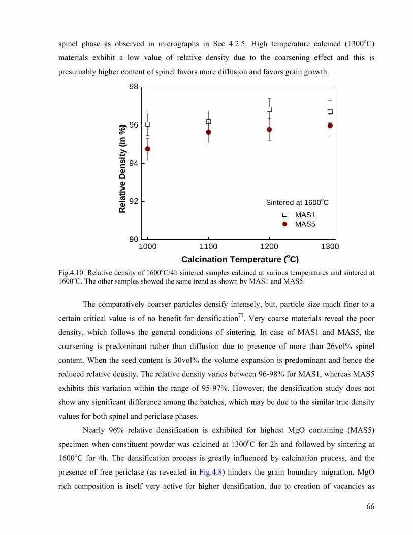
spinel phase as observed in micrographs in Sec 4.2.5. High temperature calcined (1300oC)
materials exhibit a low value of relative density due to the coarsening effect and this is
presumably higher content of spinel favors more diffusion and favors grain growth.
1000 1100 1200 130090
92
94
96
98
Sintered at 1600oC
Rela
tive
Den
sity
(in
%)
Calcination Temperature (oC)
MAS1 MAS5
Fig.4.10: Relative density of 1600oC/4h sintered samples calcined at various temperatures and sintered at 1600oC. The other samples showed the same trend as shown by MAS1 and MAS5.
The comparatively coarser particles densify intensely, but, particle size much finer to a
certain critical value is of no benefit for densification77. Very coarse materials reveal the poor
density, which follows the general conditions of sintering. In case of MAS1 and MAS5, the
coarsening is predominant rather than diffusion due to presence of more than 26vol% spinel
content. When the seed content is 30vol% the volume expansion is predominant and hence the
reduced relative density. The relative density varies between 96-98% for MAS1, whereas MAS5
exhibits this variation within the range of 95-97%. However, the densification study does not
show any significant difference among the batches, which may be due to the similar true density
values for both spinel and periclase phases.
Nearly 96% relative densification is exhibited for highest MgO containing (MAS5)
specimen when constituent powder was calcined at 1300oC for 2h and followed by sintering at
1600oC for 4h. The densification process is greatly influenced by calcination process, and the
presence of free periclase (as revealed in Fig.4.8) hinders the grain boundary migration. MgO
rich composition is itself very active for higher densification, due to creation of vacancies as
66

suggested by Hing78. The bulk density and relative density of samples varied between the two
(MAS1 and MAS5) extreme compositions. The density was seen to decrease with samples
calcined at 1300oC may be due to increased inertness at higher calcinations temperature. The
linear diametrical shrinkage of the samples was quite high and it varied between 16 and 20%.
The Apparent porosity of the sintered samples have been listed in Table 4.9 and shown in
Fig.4.11. The micrographs in Sec.4.2.5 reveal good grain size distribution with presence of pores
in between the grains in sintered samples. Microstructures shows the presence of big grains in
samples calcined at higher temperature and sintered at 1600oC/4h in comparison to the grain
size79 depicted by the powders calcined at lower temperatures followed by sintering.
1000 1100 1200 13003.0
3.2
3.4
3.6
3.8
4.0
4.2
4.4
4.6
4.8
5.0
5.2 Sintered at 1600oC/4h
Temperature (oC)
MAS1 MAS2 MAS3 MAS4 MAS5
Poro
sity
Fig.4.11: Apparent Porosity of 1600oC/4h sintered compacts with respect to temperature
Table 4.9: Apparent Porosity of sintered compacts calcined at various temperature and sintered at 1600oC
Calcination (oC)
MAS1
MAS2
MAS3
MAS4
MAS5
1000 3.93 4.22 4.59 4.92 5.25
1100 3.82 3.94 4.22 4.34 4.36
1200 3.16 3.38 3.66 3.58 4.22
1300 3.27 3.58 3.93 3.87 4.32
67

The low content of in-situ spinel seeds and low crystallite size in powders calcined at
lower temperature bring about better densification due to high reactivity. On the contrary, the
high calcination temperature increases inertness of the system, which due to coarsening effect
leads to lower densification. This leads to slight increase in porosity and decrease in density as
revealed from Fig.4.9 and 4.10. Usually a trend similar to that of density can be observed for
porosity, with a value of 5.25% for MAS5 and a low value of 3.16% for MAS1. The high value
may be due to the coarsening effect due to large grain size as revealed in the microstructure.
4.2.5. Microstructure:
Fig. 4.12 - 4.15 shows the scanning electron microscopic images of the sintered, polished
and thermally etched MgAl2O4 pellets. The precursor powders were calcined at various
temperatures for 2h, uniaxially pressed at 275MPa and sintered at 1600oC for 4h at the peak
temperature. The difference in grain morphology is due to the difference of contrast of MgO and
spinel phases. This is because the theoretical density of MgO (3.6g/cc) is higher than that of
spinel (3.58g/cc). The micrographs also exhibit white streaks which is MgO. The grains of the
magnesia rich spinel are non-uniform and pores are present in between the grains. The
micrographs reveals the presence of excess MgO (non-solid soluble in spinel) present in
between the spinel grains, which suppress grain growth and helps in densification. This
observation is supported by the X-ray diffractograms of sintered specimens.
Fig. 4.12 and 4.13 represents the microstructure of MAS1 specimen, which are calcined
at 1000 and 1300oC and sintered at 1600oC/4h. Micrograph reveals that average grain size of
MAP1 calcined at 1300oC is ~8µm in comparison to average grain size of ~5µm of MAP1
calcined at 1000oC. Similarly, Fig. 4.14 and 4.15 exhibits the microstructure of MAS5 with
relatively larger and elongated grain at around ~9 and 16µm, when specimens have been
sintered after calcination at 1000oC and 1300oC temperature respectively. Direct-bonded and
rounded spinel–spinel grains with relatively few edges are also observed. Fig 4.12 reveals that
grains of MAS1 are non-uniform and pores (intergranular) are present in between the grains.
However, some abnormal grains could be noticed in Fig 4.13 where content of in-situ crystal
seed is ~30vol%. This can be due to the coarsening effect at higher calcination temperature.
68

Fig.4.12: Microstructure of MAP1 powder calcined at 1000oC & sintered at 1600oC/4h
Fig.4.13: Microstructure of MAP1 powder calcined at 1300oC & sintered at 1600oC/4h
69
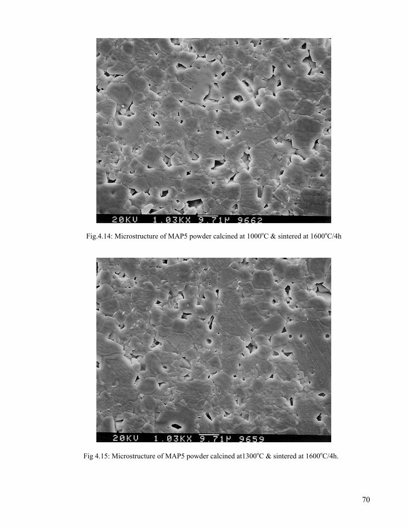
Fig.4.14: Microstructure of MAP5 powder calcined at 1000oC & sintered at 1600oC/4h
Fig 4.15: Microstructure of MAP5 powder calcined at1300oC & sintered at 1600oC/4h.
70

Fig 4.15 illustrates the microstructure of sample MAS5 which has large grain structure
and direct bonded spinel grains which confirm the results of densification parameter. The grains
in samples MAS5 seem to appear as layered grains. Abnormal grain growth was identified when
the powders calcined at 1300oC and sintered at 1600oC for 4h. Random grain orientation and increased intergranular porosity is responsible to
deteriorate the density of MAS5 specimen. From the microstructure, the average grain size
~5µm of MAS1 calcined at 1000oC and sintered at 1600oC/4h may exhibit improved room
temperature mechanical properties, whereas MAS5, calcined at 1300oC and sintered at
1600oC/4h is expected to provide better high temperature mechanical properties because of
elongated and larger grain size.
71

4.3 Mechanical and Thermal Properties
Generally, the oxide ceramics by themselves do not exhibit high fracture toughness or
strength from room temperature to elevated temperature. However through composite ceramic
materials have there is possibility of developing microstructures, where the mechanical
properties can be tailor-made to suit the service requirements. Magnesia-spinel composites have
possibilities of exhibiting good strength properties. Mechanical strength of ceramic composites
depends mainly on two parameters. One is the intrinsic property of the phases present and the
microstructure of the material. In multiphase material, microstructure of the materials, i.e. the
amount and distribution of the phases play a crucial role in determining the mechanical strength.
The test methodologies also play significant role on the strength values. According to the
application, the material can experience fully compressive strength, tensile strength and/or
intermediate of these. Actually, bend or MOR strengths are intermediate between tensile and
compressive strengths. In this chapter the hardness, compressive strength and flexural strength
tests have been carried out. Attempts have been made to correlate the compressive strength with
the bending strength values. Finally, the thermal shock resistance has been evaluated for
specimens spalled at 800oC for three cycles at room temperature.
4.3.1. Hardness:
The hardness of a material is a parameter describing its ability to withstand penetration
by a surface contact, through a combination of plastic flow and brittle fracture. Hardness of the
studied materials may be explained on the basis of the grain size and morphology. Vickers
Hardness of sintered samples with different content of spinel is shown in Fig. 4.16. Usually the
measured value of hardness is load-dependent. Especially at low loads the measured values of
microhardness tend to increase. This reflects an effect of a ratio of the impression size to a
characteristic microstructural dimension such as grain size, pore size and distribution, inclusions,
and the range of residual stresses. The microhardness also depends on the relationship of surface
properties vs. bulk properties and on environmental interactions. At high loads, such as several
kilograms, the measured hardness of ceramics decrease due to the fracture of the material during
indentation.
72

0.56 0.60 0.64 0.68 0.7212.0
12.3
12.6
12.9
13.2
13.5
MAS5
MAS4
MAS3
MAS2
MAS1
Har
dnes
s (G
Pa)
% MgAl2O4 Fig. 4.16: Hardness of various sintered specimen w.r.t increasing spinel content
1:1 1:1.1 1:1.2 1:1.3 1:1.48
9
10
11
12
13
14
15
16
Har
dnes
s (G
Pa)
Al2O3 : MgO
Load of 49N 98N 147N
Fig.4.17: Composite Hardness of specimens at different loadings with respect to Al2O3 : MgO
73

From Fig.4.16 it can be observed that the hardness of the composites had an increasing
linear relationship with increasing spinel content. The hardness of MgO-Spinel composite
(MAS1) is ~13.5GPa, which continuously decreases (13.7–12.1GPa) with the content of spinel
phase at sintered specimen. From Fig. 4.17, higher amount of seed addition has an adverse affect
on the hardness of the composites due to coarsening of the spinel grains and formation of
subsequent porosity. It has also been noticed that these composite materials also obey Hall–Petch
relationship80,81. The present study shows that the average particle size has significant impact on
mechanical properties, which is controlled by spinel seed content and initial calcination
temperature.
Fig.4.18: Optical Image of indentation shape of MAS1 (Al2O3 : MgO =1:1) at load of 98N
Fig.4.18 shows an optical image of the sintered specimen, MAS1 (Al2O3 : MgO =1:1) at a
load of 98N.
4.3.2. Diametrical Compression Test / Brazilian Disk Test:
Strength tests such as the tension test, the diametrical compression test/Brazilian disk
test65, and the simple compression test determine the limit of performance of a material to stress.
74

As such, strength criteria can be built using a combination of the local principal stresses.
Compressive strength, in general is high because the flaws in ceramics in this case are close73.
The mechanical properties of MgO-spinel composites containing preformed spinel are
more strongly influenced than the in-situ formed spinel composites by sintering temperature,
volume fraction and particle size of spinel55. The evaluation of compressive strength of spinel
based refractory has significant effect under loading57. Fig.4.19 illustrates that the compressive
strength of both of the MAS1 and MAS5 specimens does not have significant change with
respect to preformed spinel addition and/or calcination temperature.
1000 1100 1200 1300
90
105
120
135
150
165
Com
pres
sive
Stre
ngth
(MPa
)
Temperature (oC)
MAS1 MAS5
Fig.4.19: Compressive Strength (σcomp) of MAS1 and MAS5 as a function of temperature. The sintering was carried out at 1600oC/4h
Around 20% fall in strength could be noticed for MAS5, this is presumably due to: a) the
excessive grain growth of spinel phase during sintering and b) the partial bonding within
preformed spinel grain and magnesia. MgO-Spinel composites with αspinel (7.6MK-1) < αMgO
(13.5MK-1) show low strength in comparison with pure MgO, because the thermal expansion
mismatch leads to large tensile hoop stresses and microcrack development around the spinel
grains, and the radial cracks produced readily link together55. These cracks are the critical defects
causing failure on loading.
75

4.3.3. Flexural Strength:
The flexural strength of sintered specimens (50x4x4mm) has been measured using three-
point loading system. The strength at room temperature with respect to MgO addition and/or
spinel content in sintered samples is shown in Fig.4.20. Strength values in general decreased
markedly with increasing MgO content in sintered specimens. The maximum value for flexural
strength was ~137MPa, observed for MAS1 with a spinel content of ~70vol.%. The tests
revealed low strength values for high spinel content specimens, ~92MPa for MAS5 with
~56vol% spinel. The strength gradually decreases with increasing grain size as well as the
content of MgO. A similar trend could also be noticed for different calcination temperature.
1:1 1:1.1 1:1.2 1:1.3 1:1.4
90
100
110
120
130
140
Al2O3 : gO
Flex
ural
Stre
ngth
(MPa
)
1300oC 1200oC 1100oC 1000oC
Fig 4.20x= 1, 1.1
generati
microcr
spinel g
which i
microcr
: Flexural Strength of sintered specimens from 3pt., 1.2, 1.3, 1.4)
The decrease in bending strength with incre
on of microcracks (originates at the MgO
acks are the result of the large thermal expan
rains. Here the increase in microcrack popul
s major factor behind reduction of strength. A
acks occur and hence decrease in strength val
M
bend test with respect to Al2O3: xMgO (where
asing MgO content is followed with the
-spinel grain boundary interface). The
sion mismatch between the magnesia and
ation and their extension is predominant,
s MgO content increases, more extensive
ues. Nearly 15% strength loss is observed
76

in samples of two extreme compositions, calcined at 1000oC and subsequent sintering. These
cracks are the critical defects which causes failure on loading. However, a substantial decrease
(~35%) could be noticed when the starting powders were calcined at 1300oC. This is an
additional effect of increase in grain size with calcination temperature and MgO content. From
“rule of mixtures”, the calculated Young’s modulus is seen to vary within the range of
260±5GPa for any compositions, hence this effect has not been considered. Thus, the decrease in
strength of the MgO-rich spinel composites is, therefore, prone to fracture, and in particular to
the change in nature of the critical flaw size arises due to the thermal expansion mismatch within
the residual MgO grain and spinel phase.
Generally, the compressive strength of ceramic material is high and tensile strength is
low. This behavior arises because the flaws (e.g. porosity) in the ceramic are effectively closed
under compressive stress but rapidly enlarged under tensile stress (Fig. 4.21). Ceramics tend to
fail in tension so, for example, even in a three-point bend (flexural) test failure usually occurs on
the side under tensile stress commonly originating from a microstructural, strength limiting and
flaws73. The earliest studies of ceramics also revealed the trend of decreasing strength with
increased grain size or increased levels of porosity resulting in a maximum in strength as a
function of sintering temperature.
a b
Fig. 4.21: Schematic of (a) crack opening in tension but (b) closing in compression73.
From our research results it can be emphasized that the three point bending strength
exhibit lower value in comparison to compressive mode of testing. Around 10% deviation for
MAS1 could be noticed presumably due to pre-existing cracks. These cracks were generated
because of thermal expansion mismatch in between MgO grains and spinel phase.
77

4.3.4: Thermal Shock Resistance:
Fig. 4.22 shows the variation of retained flexural strength of MgO-MgAl2O4 ceramics as
a function of Al2O3: MgO ratio. The graph shows that the strength decreases with increasing
Al2O3: MgO content. This may be due to the increasing amount of MgO which has lower thermal
shock resistance. However, when retained flexural strength is plotted against calcination
temperature for a particular composition (Fig.4.23), it shows increasing trend with calcination
temperature for all the composition. This increase may be attributed to the presence of higher
amount of MgAl2O4 spinel at higher calcination temperature.
1:1 1:1.190
100
110
120
130
140
150
A
R
etai
ned
Stre
ngth
(MPa
)
1300oC 1200oC 1100oC 1000oC
Fig.4.22: Retained Strength in samples afte
Fig.4.22 shows the retained strength
continuous air requenching at 25oC from 800o
composites is attributed to the microcrack
interlinking of microcrack network leads to
amount of energy required, to initiate th
concentration of pre-existing connecting crack
1:1.2 1:1.3 1:1.4l2O3 : MgO
r Thermal Spalling of 3 cycles (Spalling at 800oC)
in sintered samples after performing 3 cycles of
C. The improved resistance to thermal shock in the
network interlinking as shown in Fig. 4.24. This
a decrease in fracture surface energy; because the
e crack propagation decreases with increasing
s.
78

1000 1100 1200 1300
90
95
100
105
110
115
120
125
130
135
140
Ret
aine
d Fl
exur
al S
treng
th (M
Pa)
Calcined Temperature (°C)
MAS1 MAS2 MAS3 MAS4 MAS5
Fig.4.23: Retained Strength in samples calcined at various temperature, after Thermal Spalling of 3 cycles
Crack
Fig.4.24: SEM micrograph of fractured surface showing intergranular fracture MAS5 (1:1.4)
The large thermal expansion coefficient difference between MgO and spinel, leads to
extensive microcracking in composite materials with loss in strength values. Lower the residual
MgO content, the lesser the concentration of pre-existing connecting cracks due to the thermal
expansion mismatch. With high content of MgO, coarser grains as revealed from microstructure
the longer cracks are generated and leading to lower fracture strength values.
79

Chapter 5 5.0. CONCLUSIONS
The MgO-MgAl2O4 powders were processed using solid-state reaction route. The
processed powder was characterized by XRD. The particle characteristics of the processed
powders were determined through particle size analyzer and BET surface area analyzer. The
densification study was carried out using high temperature dilatometer. The densification of
calcined powders was carried out for the corresponding batches. The effects of in-situ spinel
seeds (after calcination stage) on densification of corresponding batches were studied. The
sintered microstructures were analyzed through SEM studies. Subsequently, the mechanical
properties as well as the thermal shock resistance of the specimens were characterized
systematically and analyzed with respect to composition and spinel content in sintered
specimens. The overall experimental results and their analysis are represented as follows:
5.1. Powder Processing and Characterization
a) The fineness of the powders was increased with milling time. Beyond 60h, no further
reduction in fineness was observed.
b) Particle size analysis indicated a bimodal size distribution with both unagglomerated and
agglomerated particles. The average agglomerate size varied between 3.48 to 6.84µm. The
surface area of the milled powders was observed to be ~45m2/gm for powders with lowest
MgO content. The particle size of the milled powders measured from BET surface area
analyzer was found to be ~76nm and was observed to increase with increasing MgO content.
5.2. XRD Analysis of Calcined powders
(a) Calcination led to spinel phase development around 1000oC. The crystallinity as well as the
spinel content increased with increasing calcination temperature and magnesia content. The
crystallite size was 19nm and 33nm for composition with lowest and highest MgO content
respectively. The increase in crystallite size with temperature is attributed to spinel phase
development and increase with magnesia content is due to enlargement in spinel unit cell
structure due to the formation of oxygen vacant sites i.e. spinel structure becomes anion
79

deficient due to excess MgO. The average lattice parameter calculated was around 8.0792Å
for composition with highest MgO content.
(b) At calcination temperature of 1000oC; ~5vol.% spinel phase could be observed, whereas
~30vol% spinel content was observed for highest MgO content composition. The detailed
phase analysis of calcined powder illustrates a gradual trend of increasing spinel formation
with increasing calcination temperature as well as increasing MgO content. The phase
analysis of XRD revealed ~28 and ~48vol% spinel phase development at 1300oC for the
lowest and highest MgO content respectively.
(c) The surface area of the calcined powders was observed to decrease with increasing
calcination temperature and increasing MgO content. At 1000oC the surface area of the
powders was ~41m2/gm and ~24m2/gm for composition with lowest and highest MgO
content respectively. The particle size of the calcined powders measured from BET surface
area analyzer was found to increase with calcination temperature. After calcination at
1000oC, the powders revealed a particle size of 81nm and 140nm for powders with lowest
and highest MgO content respectively.
5.3. Densification Study
(a) The dilatometry study of the powders of all the composition showed a similar expansion
pattern. A sharp fall in slope was observed for MAP5; reason being the shrinkage rate from
sintering of MAP5 was higher than the expansion rate from spinel formation at about 100-
150oC lower than other batches. The presence of inherent oxygen vacancy in magnesia rich
spinel composition helps the transport of oxygen ion (the rate controlling factor), resulting in
greater extent of amphoteric diffusion, greater mass transport and densification.
(b) A green density of nearly 50% was observed for the uniaxially pressed compacts. Calcination
and subsequent spinel content has got a great influence on the sintering behavior. The higher
the calcination, the greater is the agglomeration of the starting oxides, leading to inertness
(lesser reactivity) and hence lesser shrinkage. Nearly 96-98% densification is observed for
composition with equal proportion of starting materials while it was 95-97% for highest
MgO content.
(c) The initial spinel seed content after calcination stage was observed to have a great influence
on the sintering/densification. Lower in-situ spinel seeding had beneficial effect on
densification while higher in-situ spinel seeding had a detrimental effect on density.
80

5.4. Phase and Microstructure Analysis
(a) In sintered specimens, MgAl2O4 was the major phase with a residual MgO content.
(b) An optimum amount of seed had significant effect on spinelization in MgO-rich spinel
composite. Highest spinel phase (~70%) formation in sintered specimen was observed in
presence of ~5vol% seed content in green pellets, and a gradual decreasing trend could be
noticed with increasing initial seed content. At 1300oC, spinel content of ~62vol% was
observed in sintered specimens, when initial seed content was ~28vol%. However, with
increasing MgO content, the extent of spinel phase formation decreased and reached upto
~50vol%.
(c) The microstructure revealed non-uniform grains with intergranular pores present in between
the grains. The average grain size of MAP1 calcined at 1300oC was observed to be ~8µm in
comparison to average grain size of ~5µm of MAP1 calcined at 1000oC. MAS5 exhibited
relatively larger and elongated grain at around ~9 and 16µm, upon sintering after calcination
at 1000oC and 1300oC temperature respectively. Direct-bonded and rounded spinel–spinel
grains with relatively few edges were also observed.
5.5. Characterization of Mechanical Properties
a) Higher amount of seed addition had an adverse affect on the hardness of the composites due
to coarsening of the spinel grains and formation of subsequent porosity. Hardness of the
material revealed an increasing linear relationship with increasing spinel content. Hardness of
MgO-Spinel ceramic (MAS1), calcined at 1000oC and sintered at 1600oC/4h was ~13.5GPa.
The hardness value was observed to decrease continuously (13.7–12.1GPa) with the content
of spinel phase in sintered specimen.
b) Around 20% fall in compressive strength could be noticed for MAS5, which can be
attributed to: (i) the excessive grain growth of spinel phase during sintering and (ii) the low
bond strength within preformed spinel grain and magnesia. In MgO-Spinel ceramics, due to
the thermal expansion mismatch between spinel grains and magnesia, microcrack is
developed around the spinel grains. These cracks are the critical defects causing failure on
loading.
(c) Flexural strength values was observed to decreased markedly with increasing MgO content in
81

sintered specimens. A decrease of ~35% could be noticed when the starting powders were
calcined at 1300oC, which is due to the increase in grain size.
(d) Nearly 15% flexural strength loss was observed in samples of two extreme compositions,
calcined at 1000oC and subsequent sintering. The decrease in strength was due to change in
nature of the critical flaw size that arises due to the thermal expansion mismatch within the
residual MgO and spinel phase.
(e) Compressive strength of MgO-spinel ceramics was observed to be higher than 3-point
flexural strength. This behavior arises because the flaws (e.g. porosity) in the ceramic are
effectively closed under compressive stress but rapidly enlarged under (tensile stress)
flexural testing arrangement.
(f) Improved resistance to thermal shock in the MgO-MgAl2O4 ceramics is attributed to the
microcrack network interlinking. A significant decrease in strength was observed with
increasing residual content of MgO in sintered samples. Lower the residual MgO content, the
lesser the concentration of pre-existing connecting cracks due to the thermal expansion
mismatch and hence better resistance to thermal shock.
(g) With increasing MgO content, the resultant spinel grains were found to be coarser. These
coarser grains led to longer cracks at MgO-spinel interface thereby leading to lower fracture
values in flexural test.
Initial calcination temperature and in-situ formation of spinel phase have significant contribution
on the composition and microstructure of sintered specimens. Around 5vol% spinel seed is
effective for the synthesis of MgO-70vol% MgAl2O4, whereas MgO-50vol% MgAl2O4 ceramic
can be synthesized in presence of ~50vol% initial seed content. Higher content of seed has no
contribution to nucleation rather it accelerates the grain growth at high temperature. This growth
of grain size is detrimental for mechanical properties. By adjusting the level of spinel phase in
the green pellets and the sintering conditions, the physical properties can be synchronized.
82

Chapter 6 SCOPES FOR FUTURE WORKS
The densification behavior of MgO-MgAl2O4 ceramics and subsequently the
mechanical properties may be enhanced by using different sintering aids and mineralizers. In the
present work, several mechanical properties have been evaluated; however, the real modes of
applications of this material are neglected. Hence, the scopes of future works are proposed as:
1. Densification study of these compositions with sintering additives like Fe2O3, TiO2,
AlCl3 etc.
2. Synthesis of low cement castables from respective developed spinel from various
compositions and their property evaluation for refractory applications
3. Evaluation of slag erosion and penetration resistance of the developed spinel compacts of
varying compositions.
83

REFERENCES 1. R. D. Maschio, B. Fabbri, and C. Fiori, Industrial applications of refractories containing
magnesium aluminate spinel, Industrial Ceramics 8 (2) (1988) 121–126.
2. A. Sainz, A. Mazzoni, E. Aglietti and A. Caballero, In Proc. UNITESR’97, 1995, pp. 387-392.
3. A. D. Karisheff, Refractory products and method of fabrication, France patent no. 350016, 24
August 1905.
4. E. Ryshkewitch, Oxide Ceramics, Academic Press, New York, 1960, pp. 257-274.
5. J. T. Bailey, R. Russel, Sintered spinel ceramics, American Ceramic Society Bulletin 47 (11)
(1968) 1025-1029.
6. V. K. Singh and R. K. Sinha, Low temperature synthesis of spinel (MgAl2O4), Mater. Lett.,
1997, 31, 281-285.
7. S. K. Behera, P. Barpanda, S. K. Pratihar and S. Bhattacharyya, Synthesis of magnesium-
aluminate spinel from autoignition of citrate-nitrate gel, Mater. Lett., 2004, 58, 1451-1455.
8. G. I. Antonov, A. V. Kushchenko, O. M. Semenenko and G. N. Shcherbenko, Synthesis of
magnesia-alumina spinel using periclase and bauxite, Ogneupory, no. 10, pp. 2-4, October, 1991.
9. G. I. Antonov, A. P. Yan’shina, S. M. Zubakov, and F. M. Menzhulina, Periclase- spinel
refractories from seawater magnesia and beneficiated chromite, Ogneupory, [9], 35-40,
September, 1971.
10. E. Kostic and I. Momcilovic, Reaction sintered MgAl2O4 bodies from different batch
compositions, Ceramurgia International, [3] n. 2, 1977.
11. W. H. Gitzen, Alumina as a ceramic material, Columbus: The American Ceramic Society,
(1970).
12. H. Winchell, Navigation in Crystallography. Bull. Geol. Soc. Am. 57 295-308, (1946)
13. F. F. Lange, B. I. Davies and D. O. Raleigh, Transformation strengthening of β"-Al2O3 with
tetragonal ZrO2, J. Am. Ceram. Soc. 66, C125-127, (1983).
14. M. L. Kronberg, Plastic deformation of single crystals of sapphire: basal slip and twining.
Acta Met. 5 , 507-524, (1957).
15. J. H. Chesters, Refractories Production and its Properties, Inst of Materials (1983).
16. H. H. Chesney, Steetley Company, 1938.
84

17. Stephen C. Carnlglia and Gordon L. Barna, Handbook of Industrial Refractories Technology:
Principles, types, properties, and applications, Noyes Publications, Fairview Avenue, Westwood,
New Jersey, U.S.A, 1992.
18. A. Rashid Chesti, In: Refractories – Manufacture properties and applications, Prentice Hall
of India, New Delhi (1991), p. 96.
19. S. C. Cooper and P. T. A. Hodson, Magnesia-magnesium aluminate spinel as a refractory,
Trans. J. Brit. Ceram. Soc., 81 (1982) 121-128.
20. W. H. Bragg, Philos. Mag., 1915, 176(30), 305.
21. E. H. Wallker Jr., J. W. Owens, M. Etinne and Don Walker, Mater. Res. Bull. 37 (2002)
1041–1050.
22. G.D. Price, S.L. Price, J.K. Burdett, Phys. Chem. Miner. 8 (1982) 69.
23. R. Dekkers and C.F. Woensdregt, Crystal structural control on surface topology and crystal
morphology of normal spinel (MgAl2O4), J. Crystal Growth 236 (2002) 441–454
24. M.A. Serry, S.M. Hammad, M. F. Zawrah, Br. Ceram. Trans. 97 (6) (1998) 175–178.
25. L. Schreyeck, A. Wlosik and H. Fuzellier, Infuence of the synthesis route on MgAl2O4 spinel
properties, J. Mat. Chem.11 (2000) 483-486.
26. H. Cinn, S. K. Sharma, T. F. Cooney and M. Nicol, Phys. Rev. B, 1992, 45(1), 500.
27. R. L. Millard, R. C. Peterson and B. K. Hunter, Am. Mineral., 1992, 77, 44.
28. G. Baudin, R. Martinez, and P. Pena, High-temperature mechanical behavior of
stoichiometric magnesium spinel, J. Am. Ceram. Soc., 1995, 8(7), 1857-1862.
29. L. Vollweiller, H. Jost and H. Housner, Key Engineering Materials, 132-136 (1997) 1814-
1817.
30. R.E. Carter, Mechanism of solid state reaction between MgO–Al2O3 and MgO–Fe2O3, J. Am.
Ceram. Soc. 44 (3) (1961) 116–120.
31. R. E. Carter, J. Am. Ceram. Soc., 44 [3] (1961), 116.
32. J. Beretka and T. Brown, J. Am. Ceram. Soc. 66 [5] (1983), 383.
33. P. Bartha, Magnesia spinel bricks-properties, production and use. In Proc. Int. Symp.
Refractories, Refractory Raw Materials and High Performance Refractory Products, ed. X.
Zhong et.al. Pergamon, Hangzhou, 1989, pp. 661-674.
34. T. Yamamura, T. Hamazaki and H. Kato, Alumina spinel castable refractories in steel
teeming ladles, Taikabutsu Overseas 12 (1992) 21-27.
35. I. S. Kainarskii, N. V. Gul’ko, E. V. Degtyareva and S. V. Totsenko, Reaction of sintered
spinel and corundum refractories with some compounds, Ogneupory, [1] 37-42, Jan., 1968.
85

36. G. I. Antonov, A. P. Yan’shina, S. M. Zubakov and F. M. Menzhulina, Periclase-Spinel
refractories from sweater magnesia and beneficiated chromite, Ogneupory [9] 35-40, Sept., 1971.
37. J.F. Pasquier, S. Komarneni, R. Roy, Synthesis of MgAl2O4 spinel: seeding effects on
formation temperature J. Mat. Sc. 26 (1991) 3797-3802.
38. G. Gusmano, P. Nunziante, E. Traversa and G. Chiozzini, The mechanism of MgAl2O4 spinel
formation from thermal decomposition of coprecipitated hydroxides, J. Eu. Ceram. Soc., 7(1991)
31-39.
39. Y. C. Ko and C. F. Chan, Effect of spinel content on hot strength of alumina-spinel castables
in the temperature range 1000-1500oC, J. Eu. Ceram. Soc. 19 (1999) 2633-2639.
40. R. Sarkar and G. Banerjee, Effect of compositional variation and fineness on the
densification of MgO-Al2O3 compacts, J. Eu. Ceram. Soc. 19 (1999) 2893-2899.
41. W. Kim and F. Saito, Effect of grinding on synthesis of MgAl2O4 spinel from a powder
mixture of Mg(OH)2 and Al(OH)3, Powder technology 113 (2000) 109-113.
42. R. Sarkar and G. Banerjee, Effect of addition of TiO2 on reaction sintered MgO-Al2O3
spinels, J. Eu. Ceram. Soc. 20 (2000) 2133-2141.
43. I. Ganesh, S. Bhattacharjee, B. P. Saha, R. Johnson, K. Rajeshwari, R. Sengupta, M. V.
Ramana Rao and Y. R. Mahajan, An efficient MgAl2O4 spinel additive for improved slag erosion
and penetration resistance of high Al2O3 and MgO-C refractories, Ceram. Int. 28 (2002) 245-
253.
44. L. B. Kong, J. Ma and H. Huang, MgAl2O4 spinel phase derived from oxide mixture
activated by a high energy ball milling process, Materials Letters 56 (2002) 238-243.
45. R. Sarkar, S. Chatterjee, B. Mukherjee, H. S. Tripathi, M. K. Haldar, S. K. Das and A.
Ghosh, Effect of alumina reactivity on the densification of reaction sintered non- stoichometric
spinels, Ceram. Int. 29 (2003) 195-198.
46. R. Sarkar, A. Ghosh and S. K. Das, Reaction sintered magnesia rich magnesium aluminate
spinel: effect of alumina reactivity, Ceram. Int. 29 (2003) 407-411.
47. R. Sarkar, S. K. Das and G. Banerjee, Effect of additives on the densification of reaction
sintered and presynthesised spinels, Ceram. Int. 29 (2003) 55-59.
48. H. S. Tripathi, B. Mukherjee, S. Das, M. K. Haldar, S. K. Das and A. Ghosh, Synthesis and
densification of magnesium aluminate spinel: effect of MgO reactivity, Ceram Int. 29 (2003)
915-918.
49. P. Barpanda, S. K. Behera, P. K. Gupta, S. K. Pratihar and S. Bhattacharyya, Chemically
induced disorder order transition in magnesium aluminium spinel, 26, 13 (2006) 2603-2609.
86
50. Z. Haijun, J. Xiaolin, L. Zhanjie and L. Zhenzhen, The low temperature preparation of
nanocrystalline MgAl2O4 spinel by citrate sol-gel process, Materials Letters 58 (2004) 1625-
1628.
51. J. Xiaolin, Z. Haijun, Y. Yongjie and L. Zhanjie, effect of the citrate sol-gel synthesis on the
formation of MgAl2O4 ultrafine powder, Mat. Sci. Engg. A 379 (2004) 112-118.
52. M. F. Zawrah, Investigation of lattice constant, sintering and properties of nano Mg-Al
spinels, Mat. Sci. Engg. A 382 (2004) 362-370.
53. A. Ghosh, R. Sarkar, B. Mukherjee and S. K. Das, Effect of spinel content on the properties
of magnesia-spinel composite refractory, J. Eu. Ceram. Soc., 24 (2004) 2079-2085.
54. C. Aksel and F. L. Riley, Effect of the particle size distribution of spinel on the mechanical
properties and thermal shock performance of MgO-spinel composites, J. Eu. Ceram. Soc. 23
(2003) 3079-3087.
55. C. Aksel, B. Rand, F. L. Riley and P. D. Warren, Mechanical properties of magnesia-spinel
composites, J. Eu. Ceram. Soc., 22 (2002) 745-754.
56. C. Aksel and P. D. Warren, Work of fracture and fracture surface energy of magnesia-spinel
composites, Composites Science and Technology 63 (2003) 1433-1440.
57. K. V. Simonov, V. D. Koksharov, A. I. Zabotka and L. A. Reinov, Thermo-mechanical and
deformation properties of periclase and magnesia-spinel refractories, Ogneupory, no.1, pp. 7-14,
January, 1983.
58. C. Haung, T. Lu, L. Lin, M. Lei and C. Huang, A study on toughening and strengthening of
Mg-Al spinel transparent ceramics, Key Engineering Materials Vols. (2006) pp. 1207-1210.
59. R. Sarkar, S. K. Das and G. Banerjee, Effect of attritor milling on the densification of
magnesium aluminate spinel, Ceram. Int. 25 (1999) 485-489.
60. I. Ganesh, B. Srinivas, R. Johnson, B. P. Saha and Y. R. Mahajan, Microwave assisted solid
state reaction synthesis of MgAl2O4 spinel powders, J. Eu. Ceram. Soc., 24 (2004) 201-207.
61. M.N.Rahaman, Ceramic Processing and Sintering, Marcel Dekker, Inc, New York 1995
edition pp -115.
62. B. D. Cullity, Elements of X-Ray Diffraction, Second Edition, 1978, p- 351.
63. D. Domanski, G. Urettavizcaya, F. J. Castro and F. C. Gennari, Mechanochemical Synthesis
of Magnesium Aluminate Spinel Powder at Room temperature, J. Am. Ceram. Soc., 87 (11)
(2004) 2020-2024.
87

64. G.R. Anstis, P. Chantikul, B.R. Lawn, D. B. Marshall, A critical evaluation of indentation
techniques for measuring fracture toughness: I. Direct crack measurements, J. Am. Cer. Soc. 64
(1981) 533.
65. A.T. Procopio, A. Zavaliangos, J. C. Cunningham, Analysis of the diametrical compression
test and the applicability to plastically deforming materials, J. Mat. Sc. 38 (2003) 3629-3639.
66. ASTM C1161-90, Standard test method for flexural strength of advanced ceramics at
ambient temperature, Annual Book of ASTM Standards, Vol. 15.01. ASTM, 1991, pp. 327-333.
67. M. Matsui, T. Takashi, I.Oda, Effects of starting materials and calcining temperature on
sintering of spinel ceramics. In Advances in Ceramics, ed. W. D. Kingery, The American
Ceramic Society, Columbus, OH, Vol 10, 1984, pp. 562-573.
68. R. Sarkar, H. S. Tripathi and A. Ghosh, Reaction sintering of different spinel compositions in
the presence of Y2O3, Mat. Lett. 58 (2004) 2186-2191.
69. H. Kenya, O. Tadashi, N. Zenbee, Effects of starting materials and calcining temperature on
sintering of spinel ceramics. Rep. Res. Lab. Eng. Mater., Tokyo Institute of Technology, No.
2,1977, pp. 85-94.
70. (a) J.T. Baitley, R. Russel Jr., Sintered spinel ceramics, Presented at the 69th Annual Meeting
of the American Ceramic Society, New York, 3 May, 1967. (b). J.T. Baitley, Preparation and
properties of dense spinel ceramics in the MgAl2O4–Al2O3 system, Ph.D. Thesis, Department of
Ceramic Engineering, The Ohio State University, 1966.
71. W. T. Bakker, J. T. Lindsay, Reactive magnesia spinel, preparation and properties, Am.
Ceram. Soc. Bull. 46 (11) (1967) 1094–1097.
72. I. Ganesh, S. Bhattacharjee, B.P. Saha, R. Johnson, Y.R. Mahajan, A new sintering aid for
magnesium aluminate spinel, Ceram. Int. 27 (7) (2001) 773–779.
73. W. E. Lee and W. M. Rainforth, Ceramic Microstructures: Property control by processing, 1st
edition, p-34, Chapman and Hall, 1994.
74. C. Aksel, Densification properties of magnesia-spinel composites, Key Engg. Mat. 264-268
(2004) 1071-1074.
75. J. T. Bailey and R. Russel, Preparation and properties of dense spinel ceramics. American
Ceramic Society Bulletin, 1971, 50, 493-496.
76. W. D. Kingery, H. K. Bowen, D. R. Uhlmann, Introduction of Ceramics, 2nd Edition, P-335,
John Wiley & Sons, 1991.
77. J. Petkovic and M. M. Ristic, The influence of specific surface area on sintering of alumina
powders, Ceramurgia 3 (1) (1973) 12-14.
88

78. P. Hing, Fabrication of translucent magnesium aluminate spinel and its compatibility in
sodium vapours, J. Mat. Sci. 11 (1976) 1919-1926.
79. Wurst, J. C. and Nelson, J. A., Lineal intercept technique for measuring grain size in two
phase polycrystalline ceramics, J. Am. Ceram. Soc., 55 (1972) 109.
80. E.O. Hall, Proc. Phys. Soc. (Lond.) B64 (1951) 747–753.
81. N.J. Petch, J. Iron Steel Inst. 174 (1953) 25–28.
82. M. W. Barsoum, Fundamentals of Ceramics, McGRAW-HILL International Editions, 1997.
89