dstatcom based five-level and seven level · pdf filemultilevel inverter for power quality...
TRANSCRIPT

IJCSIET--International Journal of Computer Science information and Engg., Technologies ISSN 2277-4408 || 01042015-012
IJCSIET-ISSUE5-VOLUME1-SERIES4 Page 1
DSTATCOM BASED FIVE-LEVEL AND SEVEN LEVEL CASCADE H-BRIDGE
MULTILEVEL INVERTER FOR POWER QUALITY IMPROVEMENT USING FUZZY
CONTROLLER
K.BINDHU MADHAVI *1, Mrs.M.SUNEETHA*2,
M.tech Student Department of Electrical and Electronics Engineering#1.
Associate professor, Department of Electrical and Electronics Engineering#2.
Abstract––Shunt compensation for medium
voltage distribution systems requires higher
rating for voltage source converters (VSCs).
Ratings of the semiconductor devices in a VSC
are always limited; therefore, for higher rated
converters it is desirable to distribute the stress
among the number of devices using multilevel
topology. Cascaded multilevel configuration of
the inverter has the advantage of its simplicity
and modularity over the configurations of the
diode-clamped and flying capacitor multilevel
inverters. Application of cascaded multilevel
converters for shunt compensation of
distribution systems has been described in
Literature. This paper presents a three-phase,
five-level and seven level cascaded multilevel
voltage source inverter based active filter for
power line conditioning to improve power
quality in the distribution network using fuzzy
controller. It can be implemented for the wind
energy system. The active filter compensates
both reactive power and harmonic currents
drawn by non-linear loads; additionally it
facilitates power factor corrections. The
compensation process is based on concept of p-q
theory. This proposed cascaded five level and
seven level active power filter system is
validated through MATLAB/SIMULINK
Platform.
I. INTRODUCTION
The electric power system has grown in size and complexity with a huge number of
interconnections to meet the increase in the
electric power demand. Moreover, the role of
long distance and large power transmission lines
become more important. Now days the requirement for power quality becomes more
and more important to keep safety of the
electrical devices and consumer satisfaction. Electric Power quality is a term which has
captured increasing attention in power
engineering in the recent years. Even though this subject has always been of interest to power
engineers; it has assumed considerable interest
in the 1990's. Electric power quality means
different things for different people. To most electric power engineers, the term refers to a
certain sufficiently high grade of electric service
but beyond that there is no universal agreement. The measure of power quality depends upon the
needs of the equipment that is being supplied.
What is good power quality for an electric motor may not be good enough for a personal
computer. Usually the term power quality refers
to maintaining a sinusoidal waveform of bus
voltages at rated voltage and frequency. Electric power quality (EPQ) problems mainly include
unbalance voltage and current, flicker,
harmonics, voltage sag, dip, swell, and power interruption [1]. These power quality problems
may cause abnormal operations of facilities or
even trip protection devices. Hence, the
maintenance and improvement of electric power quality has become an important scenario today.
Modern power systems are of complex
networks, where hundreds of generating stations
and thousands of load centers are interconnected through long power transmission and
distribution networks. Even though the power
IJCSIET--International Journal of Computer Science information and Engg., Technologies ISSN 2277-4408 || 01042015-012
IJCSIET-ISSUE5-VOLUME1-SERIES4 Page 2
generation is fairly reliable, the quality of power
is not always so reliable. Power distribution system should provide with an uninterrupted
flow of energy at smooth sinusoidal voltage at
the contracted magnitude level and frequency to
their customers. PS especially distribution systems, have numerous nonlinear loads, which
significantly affect the quality of power. Apart
from non linear loads, events like capacitor switching, motor starting and unusual faults
could also inflict power quality (PQ) problems.
PQ problem is defined as any manifested problem in voltage /current or leading to
frequency deviations that result in failure or mal
operation of customer equipment. Voltage sags
and swells are among the many PQ problems the industrial processes have to face. Voltage sags
are more severe. During the past few decades,
power industries have proved that the adverse impacts on the PQ can be mitigated or avoided
by conventional means, and that techniques
using fast controlled force commutated power electronics (PE) are even more effective. PQ
compensators can be categorized into two main
types. One is shunt connected compensation
device that effectively eliminates harmonics. The other is the series connected device, which
has an edge over the shunt type for correcting
the distorted system side voltages and voltage sags caused by power transmission system
faults.
The STATCOM used in distribution systems is
called DSTACOM (Distribution-STACOM) and
its configuration is the same, but with small modifications. It can exchange both active and
reactive power with the distribution system by
varying the amplitude and phase angle of the converter voltage with respect to the line
terminal voltage.
A multilevel inverter can reduce the device
voltage and the output harmonics by increasing the number of outputvoltage levels. There are
several types of multilevel inverters: cascaded
H-bridge (CHB), neutral point clamped,
flyingcapacitor [2-5]. In particular, among these topologies, CHB inverters are being widely used
because of their modularity andsimplicity.
Various modulation methods can be applied to
CHB inverters. CHB inverters can also increase the number ofoutput voltage levels easily by
increasing the number of H-bridges. This paper
presents a DSTATCOM with a
proportionalintegral controller based CHB multilevel inverter for the harmonics and
reactive power mitigation of the nonlinear
loads.This type of arrangements have been widely used for PQ applications due to increase
in the number of voltage levels, lowswitching
losses, low electromagnetic compatibility for hybrid filters and higher order harmonic
elimination.
II. DESIGN OF MULTILEVEL
BASED DSTATCOM
A. Principle of DSTATCOM
A D-STATCOM (Distribution Static
Compensator), which is schematically depicted
in Figure-1, consists of a twolevelVoltage Source Converter (VSC), a dc energy storage
device, a coupling transformer connected in
shunt to thedistribution network through a coupling transformer. The VSC converts the dc
voltage across the storage device into a set
ofthree-phase ac output voltages. These voltages are in phase and coupled with the ac system
through the reactance of thecoupling
transformer. Suitable adjustment of the phase
and magnitude of the D-STATCOM output voltages allows effectivecontrol of active and
reactive power exchanges between the
DSTATCOM and the ac system. Such configuration allows theDevice to absorb or
generate controllable active and reactive power.

IJCSIET--International Journal of Computer Science information and Engg., Technologies ISSN 2277-4408 || 01042015-012
IJCSIET-ISSUE5-VOLUME1-SERIES4 Page 3
Figure – 1 Schematic Diagram of a
DSTATCOM
The VSC connected in shunt with the ac system
provides a multifunctional topology which can
be used for up tothree quite distinct purposes:
1. Voltage regulation and compensation of
reactive power;
2. Correction of power factor 3. Elimination of current harmonics.
B. Control for Reactive Power Compensation
The aim of the control scheme is to maintain
constant voltage magnitude at the point where a sensitive load under system disturbances is
connected. The control system only measures
the rms voltage at the load point, i.e., no reactive
power measurements are required. The VSC switching strategy is based on a sinusoidal
PWM technique which offers simplicity and
good response. Since custom power is a relatively low-power application, PWM methods
offer a more flexible option than the
fundamental frequency switching methods favored in FACTS applications. Apart from this,
high switching frequencies can be used to
improve on the efficiency of the converter,
without incurring significant switching losses.
Figure-2 PI control for reactive power
compensation
The controller input is an error signal obtained
from the reference voltage and the rms terminal
voltage measured.Such error is processed by a
PI controller; the output is the angle δ, which is
provided to the PWM signal generator. It
isimportant to note that in this case, of indirectly
controlled converter, there is active and reactive
power exchange with thenetwork
simultaneously. The PI controller processes the
error signal and generates the required angle to
drive the error tozero, i.e. the load rms voltage is
brought back to the reference voltage.
C. Control for Harmonics Compensation
The Modified Synchronous Frame method is
presented in [7]. It is called the instantaneous
current component (id-iq) method. This is
similar to the Synchronous Reference Frame
theory (SRF) method. The transformation angle
is now obtained with the voltages of the ac
network. The major difference is that, due to
voltage harmonics and imbalance, the speed of
the reference frame is no longer constant. It
varies instantaneously depending of the
waveform of the 3-phase voltage system. In this
method the compensating currents are obtained
from the instantaneous active and reactive
current components of the nonlinear load. In the
same way, the mains voltages V (a, b,c) and the
available currents il (a,b,c) in α-β components
must be calculated as given by (4), where C is
Clarke Transformation Matrix. However, the
load current components are derived from a SRF
based on the Park transformation, where „θ‟
IJCSIET--International Journal of Computer Science information and Engg., Technologies ISSN 2277-4408 || 01042015-012
IJCSIET-ISSUE5-VOLUME1-SERIES4 Page 4
represents the instantaneous voltage vector angle
(5).
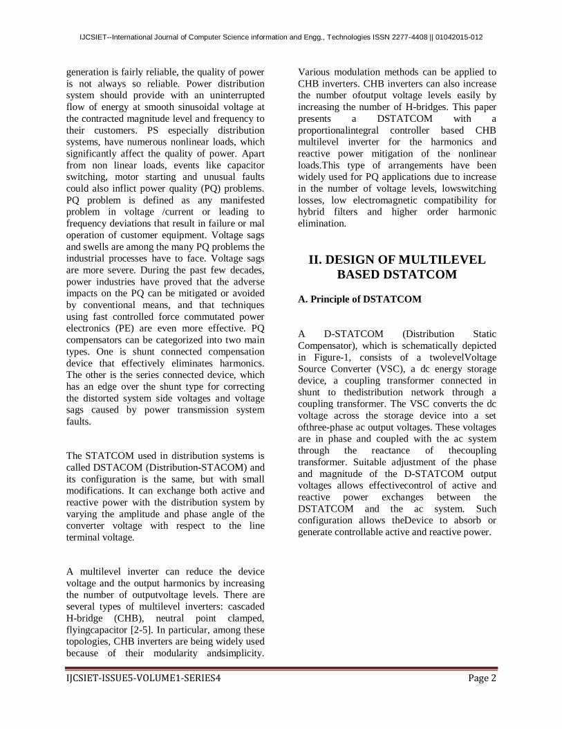
Table-1 Switching table of single CHB inverter
Figure-3 Block diagram of SRF method
D. CASCADED H-BRIDGE MULTILEVEL
INVERTER
Figure-4 Circuit of the single cascaded H-Bridge
Inverter
Fig.4 shows the circuit model of a single CHB
inverter configuration. By using single H-Bridge
we can get 3voltage levels. The number of
output voltage levels of CHB is given by 2n+1
and voltage step of each level is given
byVdc/2n, where n is number of H-bridges
connected in cascaded.
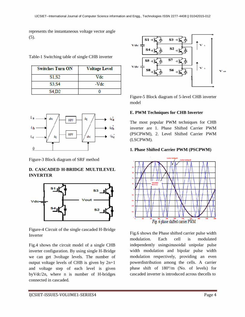
Figure-5 Block diagram of 5-level CHB inverter
model
E. PWM Techniques for CHB Inverter
The most popular PWM techniques for CHB
inverter are 1. Phase Shifted Carrier PWM
(PSCPWM), 2. Level Shifted Carrier PWM
(LSCPWM).
1. Phase Shifted Carrier PWM (PSCPWM)
Fig.6 shows the Phase shifted carrier pulse width
modulation. Each cell is modulated
independently usingsinusoidal unipolar pulse
width modulation and bipolar pulse width
modulation respectively, providing an even
powerdistribution among the cells. A carrier
phase shift of 180°/m (No. of levels) for
cascaded inverter is introduced across thecells to

IJCSIET--International Journal of Computer Science information and Engg., Technologies ISSN 2277-4408 || 01042015-012
IJCSIET-ISSUE5-VOLUME1-SERIES4 Page 5
generate the stepped multilevel output waveform
with lower distortion.
2. Level Shifted Carrier PWM (LSCPWM)
F
ig. 7 Level shifted carrier PWM
Fig.7 shows the Level shifted carrier pulse width
modulation. Each cell is modulated
independently usingsinusoidal unipolar pulse
width modulation and bipolar pulse width
modulation respectively, providing an even
powerdistribution among the cells. A carrier
Level shift by 1/m (No. of levels) for cascaded
inverter is introduced across the cellsto generate
the stepped multilevel output waveform with
lower distortion.
III. MATLAB/SIMULINK
MODELING AND SIMULATION
RESULTS
Here Matlab/Simulink model is developed for
two cases. In case one DSATCOM with Linear
load and in casetwo DSTATCOM with
nonlinear load are simulated.
A. Case one
Fig. 9 shows the Matlab/Simulink power circuit
model of DSTATCOM. It consists of five blocks
named as sourceblock, nonlinear load block,
control block, APF block and measurements
block. In this paper we use Fuzzy controller.
Fuzzy rules are as shown in table 1 Membership
functions for fuzzy variables. The variables are
normalized by multiplying with respective gains
Kin1, Kin2, Kout, so that its value lies between -1
and +1. The membership variables have 50%
overlap between adjacent fuzzy subsets. The
membership function for peed deviation,
acceleration and voltage are shown in Fig. 3.2,
3.3 and 3.4 respectively.
Fig. 8 Matlab/Simulink power circuit model
ofDSTATCOM
IJCSIET--International Journal of Computer Science information and Engg., Technologies ISSN 2277-4408 || 01042015-012
IJCSIET-ISSUE5-VOLUME1-SERIES4 Page 6
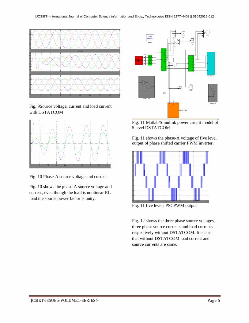
Fig. 9Source voltage, current and load current
with DSTATCOM
Fig. 10 Phase-A source voltage and current
Fig. 10 shows the phase-A source voltage and
current, even though the load is nonlinear RL
load the source power factor is unity.
Fig. 11 Matlab/Simulink power circuit model of
5 level DSTATCOM
Fig. 11 shows the phase-A voltage of five level output of phase shifted carrier PWM inverter.
Fig. 11 five levels PSCPWM output
Fig. 12 shows the three phase source voltages,
three phase source currents and load currents
respectively without DSTATCOM. It is clear
that without DSTATCOM load current and
source currents are same.

IJCSIET--International Journal of Computer Science information and Engg., Technologies ISSN 2277-4408 || 01042015-012
IJCSIET-ISSUE5-VOLUME1-SERIES4 Page 7
Fig. 12 Source voltage, current and load current
without DSTATCOM
Fig. 13 shows the three phase source voltages,
three phase source currents and load currents
respectively with DSTATCOM. It is clear that
with DSTATCOM even though load current is
non-sinusoidal source currents are sinusoidal.
Fig. 13 Source voltage, current and load current
with DSTATCOM
Fig. 14 shows the DC bus voltage. The DC bus
voltage is regulated to 11kv by using PI
regulator.
Fig. 14 DC Bus Voltage
Fig. 15 shows the phase-A source voltage and
current, even though the load is nonlinear RL
load the source power factor is unity.
Fig. 15 Phase-A source voltage and current
Fig. 16 shows the harmonic spectrum of Phase –
A Source current without DSTATCOM. The
THD of source current without DSTACOM is
36.89%.
IJCSIET--International Journal of Computer Science information and Engg., Technologies ISSN 2277-4408 || 01042015-012
IJCSIET-ISSUE5-VOLUME1-SERIES4 Page 8
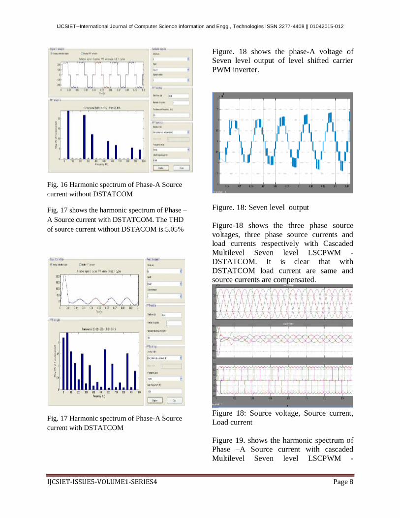
Fig. 16 Harmonic spectrum of Phase-A Source
current without DSTATCOM
Fig. 17 shows the harmonic spectrum of Phase –
A Source current with DSTATCOM. The THD
of source current without DSTACOM is 5.05%
Fig. 17 Harmonic spectrum of Phase-A Source
current with DSTATCOM
Figure. 18 shows the phase-A voltage of
Seven level output of level shifted carrier
PWM inverter.
Figure. 18: Seven level output
Figure-18 shows the three phase source
voltages, three phase source currents and
load currents respectively with Cascaded
Multilevel Seven level LSCPWM -
DSTATCOM. It is clear that with
DSTATCOM load current are same and
source currents are compensated.
Figure 18: Source voltage, Source current,
Load current
Figure 19. shows the harmonic spectrum of
Phase –A Source current with cascaded
Multilevel Seven level LSCPWM -

IJCSIET--International Journal of Computer Science information and Engg., Technologies ISSN 2277-4408 || 01042015-012
IJCSIET-ISSUE5-VOLUME1-SERIES4 Page 9
TATCOM. The THD of source current with
seven level DSTATCOM is 4.37%.
Figure. 19 Harmonic spectrum of Phase-A
Source current with DSTATCOM
IV. CONCLUSION
A seven level cascaded multilevel voltage
source inverter based active filter using a fuzzy
controller given an effective solution compared
to five-level and seven level cascaded
multilevel voltage source inverter based active
filter using instantaneous real-power controller
for power line conditioning. Shunt active filter
with the proposed fuzzy controller reduces
harmonics and provides reactive power
compensation due to non-linear load currents; as
a result source current(s) become sinusoidal and
unity power factor is also achieved under both
transient and steady state conditions. The
proposed fuzzy controller uses reduced
computation for reference current calculations
compared to instantaneous real-power controller
and conventional approach. The cascaded
inverter switching signals are generated using
triangular-sampling current controller; it
provides a dynamic performance under transient
and steady state conditions. As evident from the
simulation studies, dc bus capacitor voltage
settles early and has minimal ripple because of
the presence of fuzzy controller. The THD of the
source current when five level active power
filter is 7.34% after compensation is used by
placing PI-controller in Seven level active power
filter 4.34% and after placing a fuzzy controller
in place of PI-controller the the THD value
reduced to 2.37% which is less than 5%, the
harmonic limit imposed by the IEEE-519
standard.
REFERENCES
[1]. K.A Corzine, and Y.L Familiant, “A New
Cascaded Multi-level H-Bridge Drive,” IEEE
Trans. Power. Electron., vol.17, no.1, pp.125-
131. Jan 2002.
[2]. J.S.Lai, and F.Z.Peng “Multilevel converters
– A new bread of converters, ”IEEE Trans.
Ind.Appli., vol.32, no.3, pp.509-517. May/ Jun.
1996.
[3]. T.A.Maynard, M.Fadel and N.Aouda,
“Modelling of multilevel converter,” IEEE
Trans. Ind.Electron., vol.44, pp.356-364.
Jun.1997.
[4]. P.Bhagwat, and V.R.Stefanovic,
“Generalized structure of a multilevel PWM
Inverter,” IEEE Trans. Ind. Appln, Vol.1A-19,
no.6, pp.1057-1069, Nov./Dec..1983.
[5]. J.Rodriguez, Jih-sheng Lai, and F Zheng
peng, “Multilevel Inverters; A Survey of
Topologies, Controls, and Applications,” IEEE
Trans. Ind. Electron., vol.49, no4., pp.724-738.
Aug.2002.
[6]. Roozbeh Naderi, and Abdolreza rahmati,
“Phase-shifted carrier PWM technique for
general cascaded inverters,” IEEE Trans.
Power.Electron., vol.23, no.3, pp.1257-1269.
May.2008.
[7]. Bhim Singh, Kamal AlHaddad & Ambrish
Chandra, 1999, A Review of Active Filter for

IJCSIET--International Journal of Computer Science information and Engg., Technologies ISSN 2277-4408 || 01042015-012
IJCSIET-ISSUE5-VOLUME1-SERIES4 Page 10
Power Quality Improvements, IEEE Trans on
Industrial Electronics, 46(5), pp.960970
[8]. Mauricio Angulo, Pablo Lezana, Samir
Kouro, Jos´e Rodr´ıguez and Bin Wu,”Level-
shifted PWM for Cascaded Multilevel Inverters
with Even Power Distribution” IEEE Power
Electronics specialist conference, 17-21 June
2007, pp.2373-2378.
[9]. B. P. McGrath and D. G. Holmes,
“Multicarrier PWM strategies for multilevel
inverters,” IEEE Trans. Ind. Electron., vol. 49,
no. 4, pp. 858–867, August 2002.
K.BINDHU MADHAVI
MTECH (ELECTRICAL POWER ENGINEERING)
PURSUING IN NARAYANA ENGINEERING
COLLEGE NELLORE. Completed B.Tech (EEE) from
CHITAMS COLLEGE OF ENGG, CHITTOR,
ANDHRAPRADESH STATE, INDIA
Email id: [email protected]
Mrs. M.SUNEETHA M
TECH (PhD) ASSOCIATE PROFFESOR IN
NARAYANA ENGINEERING COLLEGE NELLORE.
MANY IEEE STUDENT BRANCH ACTIVITIES ARE
BEING RUN SUCCESSFULLY UNDER HIS
ESTEEMED GUIDANCE. AREAS OF INTEREST:
ELECTRICAL CIRCUITS, ELECTRICAL
MACHINES, POWER SYSTEMS ETC.
Email id: [email protected]