dual technology outdoor detector - securimport · pdf filedual technology outdoor detector ......
TRANSCRIPT

Port
ugue
se
Fran
çais
Es
paño
l Ita
liano
En
glis
h
Dual Technology Outdoor Detector Rivelatore da Esterno a Doppia Tecnologia
Detector Externo de Doble Tecnología Détecteur extérieur à double technologie
Detector Externo de Dupla Tecnologia
Installation Instructions - Relay & BUS Modes Istruzioni per l’installazione in modalità Relé e BUS
Instrucciones de Instalación - Modos Relé y BUS Guide d'installation - Modes Relais et BUS
Instruções de Instalação - Modos Relé & BUS

2 WatchOUT DT Installationn Manual
WatchOUT DT Installation Manual 3
Engl
ish Table Of Contents
Relay Mode Installation ............................................................................................................ 4 Introduction ............................................................................................................................... 4 Mounting .................................................................................................................................... 4
Mounting Considerations ........................................................................................................ 4 Wall Mount Installation............................................................................................................ 5 Flat Mounting: ......................................................................................................................... 5 45° angle Mounting (Left side mounting) ................................................................................ 5 Changing Back Tamper position............................................................................................. 6
Terminal Wiring ........................................................................................................................ 6 DIP Switch Settings.................................................................................................................... 7 Microwave Adjustment ............................................................................................................. 7
Walk test ................................................................................................................................. 7 LEDs Display .............................................................................................................................. 7 Relay Mode / BUS Mode Jumper............................................................................................. 7 Standard Swivel Installation .................................................................................................... 8
Wall Mounting ......................................................................................................................... 8 Swivel Conduit Mounting (using Conduit Metal Swivel Adaptor – CSMA, Figure 6, Detail A) ................................................................ 8
Replacing a Lens ..................................................................................................................... 10 Lenses Types ....................................................................................................................... 11
Technical Specification ........................................................................................................... 12 Ordering Information ............................................................................................................. 12 BUS Mode Installation ............................................................................................................ 13 Introduction ............................................................................................................................. 13 Terminal Wiring ...................................................................................................................... 13 DIP Switch Settings.................................................................................................................. 13 ProSYS Programming.............................................................................................................. 14 New System Parameters......................................................................................................... 16

4 WatchOUT DT Installation Manual
Relay Mode Installation
Introduction RISCO Group's Dual Technology Outdoor detector, WatchOUT, is a unique detector with signal processing based on two Passive Infrared (PIR) channels and two Microwave (MW) channels. The detector can operate as a regular relay detector connected to any control panel, or as a BUS accessory when connected to RISCO Group's ProSYS control panel via the RS485 BUS, thus having unique remote control and diagnostic capabilities. The instructions describe herein, describe the WatchOUT in Relay & BUS mode.
Mounting Mounting Considerations
If possible, avoid pointing the detector to moving objects (swaying trees, bushes etc.)
1m - 2.7m(3'3" - 8'9")
Optional Height: 1m – 2.7m (3'3"-8'9") Typical Height: 2.2m (7'2") Default Lens: Wide angle 15m (50') 90° (RL300)
Note: 1. For low installations, below 1.7m (5'6") in which
pet immunity is required, use the supplied RL300F lens (low wall or fence installations).
2. The detector's pet immunity (height of an animal, no weight limitation), is up to 70 cm (2'4"), when installing the detector at 2.2m (7'2"). If the installation is bellow the height mentioned above, the Pet Immunity decreases accordingly; every 10 cm (4") decrease in installation height leads to 10 cm (4") decrease in pet imunity.
Out ofDetection Range
Keep distance of minimum 5m (16') from moving objects
5m (16')
Ensure any objects do not obstruct the field of view for both technologies. Pay attention to growing trees or bushes, plants with big moving leaves etc
For installations with extensive vehicle traffic or targets beyond the required detection range, it is recommended to adjust the MW sensitivity and/or to tilt the detector down. Note: Tilting the detector down may reduce the pet immunity
For optimum detection, select a location that is likely to intercept an intruder moving across the coverage pattern at a 45° trajectory.

WatchOUT DT Installation Manual 5
Engl
ish Wall Mount Installation
Figure 1
C1
Figure 2 I1
Figure 3
TamperLever
A
T5T1
B2
W9
B3
W2
B
L1
T3
B1
L2
W3
B4
R1
R2(not visible)
T2
T6
(not visible)
T4
W5
W6
Note: The installation knockouts numbering are marked on the back plate.
1. Open WatchOUT front cover (unlock C1, Figure 1).
2. Release internal base (unlock I1, Figure 2).
3. Select mounting installation as follows:
Flat Mounting: Open knockouts on external base (Figure 3).
• B1 - B4: Wall mounting knockouts • T1: Back tamper knockout • W2 / W3: wires entry knockouts
45° angle Mounting (Left side mounting)
a. Open knockouts on external base (Figure 3) • L1, L2: Left mounting knockouts • T3: Left tamper knockout • W5 / W6: Wire entry knockouts
b. Remove tamper spring. c. Replace tamper bracket (Item 1) with
supplied flat tamper bracket (Item 2). Item 1
Item 2
d. Insert Tamper lever B onto T5 and T3
and secure screw A (Figure 3).
4. Insert external wires through external base W2, W3 (Flat Mounting) or W5, W6 (Left side mounting) (Figure 3).
5. Secure external base to the wall.
6. Insert external wires and tamper wires through internal base (Figure4).
7. Secure internal base to external base (lock I1, Figure2).
8. Close the front cover (Lock C1, Figure1) after wiring and setting DIP switches.
9. Walk test the detector.
Figure 4
Note: For 45° right side installation use the equivalent units on the external base as follows:
Knockouts Description Left Right Mounting Knockouts L1, L2 R1, R2 Tamper spring knockouts T1,T3 T2,T4 Tamper screw anchor T5 T6 Wiring Knockouts W5, W6 W7, W8

6 WatchOUT DT Installation Manual
Changing Back Tamper position The back tamper is by default secured on the right side of the internal base (rear view). If you wish to move it to the left side (rear view), do the following (Figure 5): 1. Remove tamper screw 1 in order to release the
tamper from position 7. 2. Ensure tamper spring 2 rests over tamper wire
base 4. 3. Ensure plastic tamper bracket 3 rests over both
2 and 4. 4. Secure tamper screw 1 into 3 over position 6.
Figure 5 Left Side Tamper
Right Side Tamper
3
6
1
2
4
7
5
Notes: 1. Verify that you hear a "Click" when attaching the tamper spring to the wall. 2. For pole installation, the tamper can be moved to the bottom right-hand side of the internal base.
Terminal Wiring
+ - SET/UNSET
LEDsENABLAMYEL
FREEALARM TAMPER GREENFREE DUST TEST
12VDC
N.C N.C WatchOUT DT - PCB +,- 12 VDC ALARM N.C relay, 24VDC , 0.1A FREE YEL This terminal is a free pin that can be used to connect wires and EOL resistors TAMPER N.C relay, 24VDC , 0.1A FREE GREEN
This terminal is a free pin that can be used to connect wires and EOL resistors
AM Normally closed AM relay output (24VDC, 0.1A) indicates Anti Masking alarm or any trouble in the detector (Not including dust/dirty lens).
Note: When a vibration detector is installed and DIP8 is defined as Enabled this relay also opens momentarily when vibration event occurs.
LED ENABLE
Used to remotely control the LEDs when DIP1 is set to ON. Enable: input is +12V OR no terminal connection Disable: Connect the input to 0V
DUST N.O. collector max 70 mA. Indicates that the lens is dirty and requires cleaning. TEST Used to perform remote alarm testing to the detector by applying 0 volts to this
terminal. Success: Alarm relay is momentary opened. Failure: AM relay is opened This input enables to control Anti-masking and LEDs operation in accordance to the system status, Set (Arm) / Unset (Disarm). While the system is armed this feature prevents an intruder from gaining knowledge of the detector’s status and disables Anti-masking detection.
SET/ UNSET
System Status Input Status AM Relay LEDs Set (Arm) 0V Off Off Unset (Disarm) 12V or no connection On* On**
* DIP7 is ON (Anti masking enabled) ** DIP1 is ON (LEDs enabled) and LEDs ENABLE input terminal is enabled
(+12V OR no terminal connection)

WatchOUT DT Installation Manual 7
Engl
ish DIP Switch Settings
1 2 3 4 5 6 7 8
ON
FactoryDefault
DIP 1: LEDs operation
On: LEDs Enabled Off: LEDs Disabled
DIP 2-3: Detection Sensitivity Sensitivity DIP2 DIP3 Low Off Off Mid Off On Normal (Default)
On Off
Maximum* On On * In maximum sensitivity sway recognition is disabled to achieve maximum sensitivity
DIP 4: Alarm condition On: PIR or MW Off: PIR + MW
DIP 5: Detector's optics On: Barrier / Long range Off: Wide angle
DIP 6: Red LED /3 LED On: Red LED only Off: 3 LEDs
DIP 7: Anti masking operation On: Enabled Off: Disabled
DIP 8: Vibration detection (applicable to versions with Vibration sensor installed) On: Enabled Off: Disabled
Microwave Adjustment Adjust Microwave coverage area by using the trimmer on the PCB.
MIN MAX
Walk test Two minutes after applying power, walk test the protected area to verify proper operation. For installations on uneven surfaces slide the PCB inside the internal base to the appropriate setting according to the desired height (1.0m, 1.5m, 2.2m, 2.7m) as printed on the bottom left corner of the PCB or use the standard swivel accessory.
For reducing the detection range, slide the PCB up or tilt the swivel down.
1.00M
1.50M
2.20M2.70M
PCB
LEDs Display LED State Description
Steady Indicates PIR detection YELLOW Flashing Indicates AM (Anti mask) detection
GREEN Steady Indicates MW detection
Steady Indicates ALARM RED Flashing Indicates malfunctioned communication with ProSYS (BUS
mode only)
All LEDs Flashing (One after another)
Unit initialization on power up
Notes: 1. DIP-Switch 1 should be in ON position to enable LED indications. 2. Only one LED is active at any one time. For example, in the case of both PIR and MW detection, either the
steady YELLOW LED or the steady GREEN LED is displayed (the first to detect), followed by the Alarm RED LED.
Relay Mode / BUS Mode Jumper J-BUS jumper (located on the PCB between the red and green LEDs) is used to define the detector’s mode of operation as follows:
Relay Mode
BUS Mode

8 WatchOUT DT Installation Manual
Standard Swivel Installation The Outdoor detector packaging contains a standard swivel for flexible installation. Please follow the instructions below for mounting the detector with the Standard Swivel:
1. Open WatchOUT front cover (Unlock C1, Figure1).
2. Release internal base (Unlock I1, Figure 2).
3. Open knockouts on external base (Figure 6, Detail B) • W1: Wires knockout • S1,S2: Knockouts for securing external base to Standard Swivel • S3: External base locking screw knockout
4. On the swivel accessory remove the required swivel cable wiring knockout S2, S7 or S9 (Figure 6, Detail A).
5. Remove back tamper from the internal base (see “Changing Back Tamper Position" paragraph) and connect it to S5 (Figure 6, Detail A) on the Standard Swivel.
Note: Ensure that you see the engraved UP mark on the upper front face of the swivel.
6. Select the mounting installation type as follows:
Wall Mounting a. Insert external cable wiring through knockouts S2, S7 or S9 and extract them (including the
tamper wires) through the Swivel Wires Passage (Figure 6, Detail B).
b. Secure swivel to the wall through holes S1, S3, S6 and S8.
Swivel Conduit Mounting (using Conduit Metal Swivel Adaptor – CSMA, Figure 6, Detail A)
S1 S2 S3
S9
S8
S7 S6S5
S4
Tamper (see Detail C)
Swivel WiresPassage
Tamper SpringHoles
Ø 21 mm
Ø 16 mmCSMA
M1
M2
M3
M4
Detail A Detail B
S1
W1
S2
S3
Snaps
Standard Swivel
Detail C
Figure 6
Note: The CSMA is required when wall external wiring is used and protection pipe is required. The CSMA should be ordered separately - P/N RA300SC0000A.
a. Choose the direction upon which to mount the CSMA according to the required diameter: 16mm (0.63 inches) or 21mm (0.83 inches).
b. Insert conduit to the CSMA.
c. Secure CSMA to the wall through points (M1, M4).
d. Insert external cables and tamper wires from the conduit through the swivel wires passage of the swivel (Figure 6, Detail A).
e. Secure swivel to the wall through holes S1, S3, S6 and S8.

WatchOUT DT Installation Manual 9
Engl
ish
Note: The Tamper spring S5 (Figure 7) should make contact with the wall through the tamper spring holes M2 or M3 on the CSMA. Make sure to hear the tamper "Click" when connecting to the wall.
7. Insert tamper wires and external cable wiring from Standard Swivel through knockout W1 on the external base (Figure 6, Detail B).
8. Connect the external base to the swivel using the dedicated snaps (Figure 7).
PCB
External Base
Internal Base
Angle Locking Screw
(See Note 2)
See Detail A
Swivel to External Base Connecting Screws
Detail A
Swivel AssyConnecting Screw
(See Note)
Snaps
S1
W1
S2
S3
Figure 7
NOTE: Do not open or close the Swivel Assy Screw since it is used for connecting the swivel parts only.
9. Secure external base to swivel with two screws fastened to knockouts S1 and S2 (Figure 7). 10. Insert the supplied angle locking screw from the external base through the angle locking screw
knockout S3 on the external base to the standard swivel (Figure 7). 11. Tilt and Rotate the Standard Swivel to the desired position. Once the Standard Swivel is in the
desired position, secure the angle locking screw. 12. Line up the internal base onto the external base. Insert all wiring cables through the internal
base. 13. Secure internal base to external base (Lock I1, Figure 2). 14. To readjust the Standard Swivel when the PCB is installed (Figure 7):
a. Bend down the black foam located below the RED LED on the PCB (enough to reach the Swivel locking screw).
b. Use a Philips screwdriver to release the locking screw (see Figure 8). c. Tilt and/or Rotate the Standard Swivel to the desired position. d. Secure the angle locking screw. Note: When marks on the two movable parts are aligned (Figure 8), the Standard Swivel is in 0° vertical /horizontal position. Each click from this position represents shifting of 5° in vertical / horizontal position.
15. Close the front cover (Lock C1, Figure 1) and walk test the detector.

10 WatchOUT DT Installation Manual
NOTE: The screw has to pass through External Base and locked to the swivel.
Figure 8
Replacing Lenses 1. Unlock the six screws that hold the lens holding sleeve from the back of the front cover.
2. To release the protective sleeve, gently push the lens from the external side of the front cover.
3. Disconnect the lens from the sleeve by gently pushing the lens clips that secure it to the sleeve.
4. Replace the lens. Place the 4 clips of the lens into the matching holes on the sleeve.
5. Insert the protective sleeve back into place on the front cover. Pay attention to place the sleeve over the sealing rubber.
6. Secure the 6 holding screws back to their place.
Lens ProtectingSleeve
Sockets forLens Clips
Sleeve LockingScrews
Lens LockingClips
Sealing Rubber
Front CoverLocking Screw

WatchOUT DT Installation Manual 11
Engl
ish Lens Types
Wide angle lens (RL300) / Low installation - Pet lens (RL300F) :
Top view 11
11
Feet0
0
10 20 30 40 50
10
20
30
40
10
20
30
40 2 4 6 8 100 12 14 15
1
3
5
7
9
01
3
5
7
9
90°
Wide angle lens (RL300): Side View
Typical Installation
Height:2.2m (7'2")
0
10
2 4 6 8 100 12 14 15
0 10 20 30 40 50
1
3
0
Feet
MetersFeet
Low installation - Pet lens (RL300F) : Side view
Feet
0
6
2 4 6 8 100 12 14 15
0 10 20 30 40 50
10
2
Meters
FeetTypical Installation
Height:1.5m (5'3")
Note: The detector's Pet Immunity (height of an animal, no weight limitation), is up to 70 cm (2'4"), when installing the detector at 2.2m (7'2"). If the installation is bellow the height mentioned above, the Pet Immunity decreases accordingly; every 10 cm (4") decrease in installation height leads to 10 cm (4") decrease in pet imunity.
Long range lens (RL300LR): Top view
2 4 6 8 100 12 14 16 18 20 22 23
0 10 20 30 40 50 60 70 75
101
03
3
Feet
MetersFeet
5°
Barrier lens (RL300B): Top view
2 4 6 8 100 12 14 15
0 10 20 30 40 50
101
03
3
Feet
MetersFeet
5°
Long range lens (RL300LR): Side view
0
10
1
3
0
2 4 6 8 100 12 14 16 18 20 22 23Meters
0 10 20 30 40 50 60 70 75
Feet
Typical Installation
Height:2.2m (7'2")
FeetBarrier lens (RL300B): Side view
2 4 6 8 100 12 14 15
0 10 20 30 40 50Feet
Meters0
10
1
3
0
Typical Installation
Height:2.2m (7'2")
Feet

12 WatchOUT DT Installation Manual
Technical Specification Electrical
45mA at 12 VDC (Stand by) Current consumption (Relay Mode) 70mA at 12 VDC (MAX with LED ON) 30mA at 12 VDC (Stand by), Current consumption (BUS Mode) 55mA at 12 VDC (MAX with LED ON)
Voltage requirements 9 -16 VDC Alarm contacts 24 VDC, 0.1A AM contacts 24 VDC, 0.1A Dust output Open collector 70mA max Physical Size: LxWxD
220 x 115 x 123mm (8.7 x 4.5 x 4.85 in.)
Weight 0.632 Kg (1.4lb) Environmental RF immunity (30MHz to 2GHz): 40V/m Operating/Storage temperature -30°C to 60°C (-22°F to 140°F)
Ordering Information
Standard Units Part Number Description RK315DT0000A WatchOUT DT 10.525GHz + Swivel RK315DT00UKA WatchOUT DT 10.587GHz + Swivel RK315DT00FRA WatchOUT DT 9.9GHz + Swivel
Note:
Each of the detectors contains a standard swivel and 3 replacement lenses (P/N engraved on the Lens) 1.7m low installation pet (RL300F), long-range (RL300R) and barrier lens (RL300B).
Accessories Kits Part Number Description Weight RA300B00000A WatchOUT Barrier Swivel Kit 0.1 Kg (0.23 lb) RA300P00000A WatchOUT Pole Adaptor Kit 0.25 Kg (0.55 lb) RA300C00000A WatchOUT Conduit Adaptor Kit 0.6 Kg (1.27 lb) RA300HS0000A WatchOUT Demo Housing - - RA300SC0000A WatchOUT Swivel Metal Conduit Adaptor 1Kg (2.2 lb)
Camera Option Part Number Description RA300VC0001A WatchOUT Camera Cover Adaptor 1 RA300VC017NA NTSC Narrow Camera For WatchOUT RA300VC053NA NTSC Wide Camera For WatchOUT RA300VC053PA WatchOUT PAL Wide Camera kit RA300VC017PA WatchOUT PAL Narrow Camera kit RA300VPS100A WatchOUT 220V PAL Camera Power supply RA300VPS200A WatchOUT 120V Camera Power supply

WatchOUT DT Installation Manual 13
Engl
ish BUS Mode Installation
Introduction The information in this section relates to WatchOUT DT installation in BUS Mode only. Up to 32 BUS detectors can be installed on the ProSYS RS485 BUS, saving cabling time and enabling remote control and diagnostics.
Terminal Wiring +,- Used for the connection of 12VDC power supply. Connect the (+) terminal to
the AUX RED and the (–) terminal to the COM BLK of the ProSYS terminals YELLOW Used for data communication with the ProSYS. Connect to the terminal to the
BUS YEL of the ProSYS GREEN Used for data communication with the ProSYS. Connect to the terminal to the
BUS GRN of the ProSYS
TAMPER Used for the wiring for tamper detection, see below
LED ENABLE
Used for the wiring for tamper detection, see below
Note: All terminals that are not mentioned in the table above are unused.
Cover and Back Tamper
+ - SET/UNSET
LEDsENABLE
AMYEL
FREEALARM TAMPERGREENFREE
DUST TEST
COMBLK
BUSGRNYEL
BUS Mode:Cover + Back tamper wiring
BACKTAMPER (N.C)
ProSYS
ShortAUXRED
Cover Tamper Only
+ - SET/UNSET
LEDsENABLE
AMYEL
FREEALARM TAMPERGREENFREE
DUST TEST
COMBLK
BUSGRNYEL
BUS Mode:Cover Tamper Wiring
ProSYS
ShortAUXRED
Cover Tamper to Zone Input
+ - SET/UNSET
LEDsENABLE
AMYEL
FREEALARM TAMPERGREENFREE
DUST TEST
COMBLK
BUSGRNYEL
BUS Mode:Cover Tamper to Zone Input
ProSYSBUS
Short
ZoneCOMZ1 Z2
ZoneInput
AUXRED
DIP Switch Settings DIP Switch Number
Description
1 - 5 Used to set the detector ID number. Set the ID number in the same way as for any other ProSYS accessory (Refer to the ProSYS installation instruction manual)
6 - 8 Not used

14 WatchOUT DT Installation Manual
WatchOUT ID: DIP Switches 1 - 5 ID 1 2 3 4 5 ID 1 2 3 4 5 01 OFF OFF OFF OFF OFF 17 OFF OFF OFF OFF ON 02 ON OFF OFF OFF OFF 18 ON OFF OFF OFF ON 03 OFF ON OFF OFF OFF 19 OFF ON OFF OFF ON 04 ON ON OFF OFF OFF 20 ON ON OFF OFF ON 05 OFF OFF ON OFF OFF 21 OFF OFF ON OFF ON 06 ON OFF ON OFF OFF 22 ON OFF ON OFF ON 07 OFF ON ON OFF OFF 23 OFF ON ON OFF ON 08 ON ON ON OFF OFF 24 ON ON ON OFF ON 09 OFF OFF OFF ON OFF 25 OFF OFF OFF ON ON 10 ON OFF OFF ON OFF 26 ON OFF OFF ON ON 11 OFF ON OFF ON OFF 27 OFF ON OFF ON ON 12 ON ON OFF ON OFF 28 ON ON OFF ON ON 13 OFF OFF ON ON OFF 29 OFF OFF ON ON ON 14 ON OFF ON ON OFF 30 ON OFF ON ON ON 15 OFF ON ON ON OFF 31 OFF ON ON ON ON 16 ON ON ON ON OFF 32 ON ON ON ON ON
ProSYS Programming The following section describes the additional software programming options, added to the ProSYS software, that concern the settings of the WatcOUT DT as a BUS detector. Up to 32 BUS detectors can be added to the system (16 in ProSYS 16) and each of them comes at the expense of a zone in the system. It is recommend reading and fully understanding the ProSYS Installation and User Manuals, before programming the WatchOUT
Notes: The WatchOUT is compatible with the ProSYS software Version 4.xx and above. The WatchOUT can be programmed via the U/D Software from UD Version 1.8 and above. For maximum operation stability, it is best NOT to exceed a total of 300 meters (1000 feet) of wiring when connecting the WatchOUT to the BUS.
Adding / Deleting the WatchOUT DT
The WatchOUT is part of a new accessory category, BUS zones. Therefore, Adding/Deleting the WatchOUT is identical to any other accessory with the following exception: Each BUS Zone Detector should be assigned to a Regular Zone. Any BUS detector can be assigned to a physical wired zone or to a virtual zone.
Physical zone: Any zone on the ProSYS PCB (zones 1-8) or on a wired zone expander (ZE08, ZE16). Virtual zone: Any zone on a BUS zone expander defined as BZ08 or BZ16.
Notes: Virtual BUS zones are cost effective. They enable to expand your system zones without adding physical zone expanders. The virtual BUS zone expander can be used only for BUS zone detectors. To add a BUS zone expander select type BZ08 or BZ16 when adding a zone expander (Quick key [7][1][2]).
1. To Add / Delete the WatchOUT DT 1. From the installer menu enter the Add/Delete menu: Quick Key [7][1][9][5] for BUS Zones
detectors.
2. Use the / or / keys to position the cursor over the BUS Zone ID number for which you want to assign (or delete) a detector.
Note: Make sure that the detector's physical ID number is identical to the ID number you select during programming.
WatchOUT DT Installation Manual 15
Engl
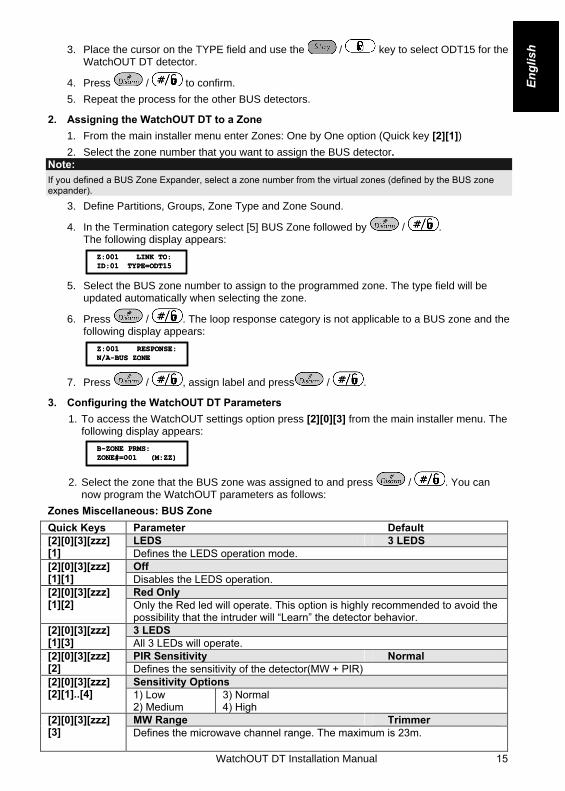
ish 3. Place the cursor on the TYPE field and use the / key to select ODT15 for the
WatchOUT DT detector.
4. Press / to confirm.
5. Repeat the process for the other BUS detectors.
2. Assigning the WatchOUT DT to a Zone 1. From the main installer menu enter Zones: One by One option (Quick key [2][1]) 2. Select the zone number that you want to assign the BUS detector.
Note: If you defined a BUS Zone Expander, select a zone number from the virtual zones (defined by the BUS zone expander).
3. Define Partitions, Groups, Zone Type and Zone Sound.
4. In the Termination category select [5] BUS Zone followed by / . The following display appears:
Z:001 LINK TO:ID:01 TYPE=ODT15Z:001 LINK TO:ID:01 TYPE=ODT15
5. Select the BUS zone number to assign to the programmed zone. The type field will be
updated automatically when selecting the zone.
6. Press / . The loop response category is not applicable to a BUS zone and the following display appears:
Z:001 RESPONSE:N/A-BUS ZONEZ:001 RESPONSE:N/A-BUS ZONE
7. Press / , assign label and press / .
3. Configuring the WatchOUT DT Parameters 1. To access the WatchOUT settings option press [2][0][3] from the main installer menu. The
following display appears:
B-ZONE PRMS:ZONE#=001 (M:ZZ)B-ZONE PRMS:ZONE#=001 (M:ZZ)
2. Select the zone that the BUS zone was assigned to and press / . You can now program the WatchOUT parameters as follows:
Zones Miscellaneous: BUS Zone Quick Keys Parameter Default
LEDS 3 LEDS [2][0][3][zzz] [1] Defines the LEDS operation mode.
Off [2][0][3][zzz] [1][1] Disables the LEDS operation.
Red Only [2][0][3][zzz] [1][2] Only the Red led will operate. This option is highly recommended to avoid the
possibility that the intruder will “Learn” the detector behavior. 3 LEDS [2][0][3][zzz]
[1][3] All 3 LEDs will operate. PIR Sensitivity Normal [2][0][3][zzz]
[2] Defines the sensitivity of the detector(MW + PIR) Sensitivity Options [2][0][3][zzz]
[2][1]..[4] 1) Low 2) Medium
3) Normal 4) High
MW Range Trimmer [2][0][3][zzz] [3] Defines the microwave channel range. The maximum is 23m.

16 WatchOUT DT Installation Manual
Quick Keys Parameter Default MW Range options [2][0][3][zzz]
[3][1]..[7] 1) Minimum 2) 20%
3) 40% 4) 60%
5) 80% 6) Maximum
7) Trimmer (MW is defined by the trimmer setting on the PCB)
Alarm Logic PIR and Microwave [2][0][3][zzz] [4] Determine the detector’s logic of defining an alarm.
PIR and Microwave [2][0][3][zzz] [4][1] Alarm is activated when both PIR and MW channels detect an alarm
(AND Logic) PIR or Microwave [2][0][3][zzz]
[4][2] An alarm is activated when either PIR or MW channels detect an alarm (OR Logic) Lens Type Wide Angle [2][0][3][zzz]
[5] Defines the actual Lens of the detector
Lens Type Options [2][0][3][zzz] [5][1]..[2] 1) Wide Angle 2) Barrier / Long Range
Anti-Mask Enable [2][0][3][zzz] [6] Defines the operation of Anti Masking detection
Anti-Mask Options [2][0][3][zzz] [6][1]..[2] 1) Disable 2) Enable (Default)
Arm/Disarm No [2][0][3][zzz] [7] Defines the operation of the LEDs anti masking detections while the detector
is armed No [2][0][3][zzz]
[7][1] AM (Anti masking) is enabled LEDs behave according to the LEDs parameter definition Yes [2][0][3][zzz]
[7][2] AM (anti masking) is disabled LEDs are disabled
System Parameters
System: System Control
Quick Keys Parameter Default:
AM=Tamper No [1][2][36] Used to determine the operation of Anti Masking detection Yes: Anti mask violation will activate tamper alarm. No: Anti mask violation will be regarded as trouble event.
VBR=Tamper No [1][2][37] Used to determine the operation of the vibration detection (applicable to versions with Vibration sensor installed) Yes: Vibration detection will activate tamper alarm. No: Vibration detection will be regarded as trouble event.

WatchOUT DT Installation Manual 17
Engl
ish Diagnostics
The ProSYS enables you to test parameters that reflect the operation of the detector.
1. From the main user menu press [4] to access the Maintenance menu.
2. Enter the Installer code (or sub-installer) and press / . 3. Press [9] [1] to for the BUS Zones diagnostic menu.
4. Enter the digit of the zone that you want to test and then press / . The system will perform the diagnostics test and a list of test parameters will appear, as indicated in the table below.
5. Use the keys / / to view the diagnostics test results.
User Menu: 4) Maintenance → 9) Diagnostic → 1) BUS Zone
Quick Keys Parameter [4][9][1][zzz] Detector Input Voltage: Display the input voltage of the detector.
PIR 1 Level: PIR channel 1 DC level. Range 0.1v - 4v PIR 1 Noise Level: PIR channel 1 AC level. Range 0VAC (No noise) - 4VA PIR 2 Level: PIR channel 2 DC level. Range 0.1v - 4v PIR 2 Noise Level: PIR channel 2 AC level. Range 0VAC (No noise) - 4VA MW 1 Level: MW channel 1 DC level Range 0.1v - 4v MW 1 Noise Level: MW channel 1 AC level (0VAC (No noise) - 4VAC) MW 2 Level: MW channel 2 DC level Range 0.1v - 4v MW 2 Noise Level: MW channel 2 AC level (0VAC (No noise) - 4VAC