soutdoor l installation v1.0 double pir outdoor detector
TRANSCRIPT

www.amcelettronica.com Installation Instructionssoutdoor L
soutdoor L instaLLationv1.0
Double PIR outdoor Detector
1. introductionengLish
SOUTDOOR-L is a Dual Digital PIR sensor, with an analysis system that takes into account the two most important changes that may occur during a movement: the speed and the intensity. With the simultaneous comparisonof these two information, the sensor is able to discriminate repetitive movements from intrusion, loweringthe percentage of false alarms. With hight thermal variations, the totally digital temperature compensationsystem, guarantees a great performance. Has 15mt coverage, with angle of 90 °. With usable different type of lens it is possible use the sensor in different situation, related to the height positioning, and the type of protection required, eg. curtain protection etc.
Characteristics:• Dual technology outdoor sensors (2 digital PIR with 4 seconds AND operation).• Different types of lenses depending on the type of installation (volumetric; vertical/horizontal).• PET immune.• Back tamper and anti-opening tamper.• Range adjustable 6 meters or 12 meters.• Walking test led • Double pulse• Bracket
www.amcelettronica.com Installation Instructionssoutdoor L
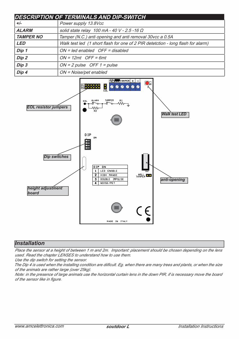
description of terMinaLs and dip-sWitch+/- Power supply 13.8VccaLarM solid state relay 100 mA - 40 V - 2.5 -16 ΩtaMper no Tamper (N.C.) anti opening and anti removal 30vcc a 0.5ALed Walk test led (1 short flash for one of 2 PIR detetction - long flash for alarm)dip 1 ON = led enabled OFF = disableddip 2 ON = 12mt OFF = 6mtdip 3 ON = 2 pulse OFF 1 = pulsedip 4 ON = Noise/pet enabled
Dip switches
EOL resistor jumpersWalk test LED
anti-opening
height adjustmentboard
InstallationPlace the sensor at a height of between 1 m and 2m. Important: placement should be chosen depending on the lens used. Read the chapter LENSES to understand how to use them.Use the dip switch for setting the sensor.The Dip 4 is used when the installing condition are diificult. Eg. when there are many trees and plants, or when the size of the animals are rather large (over 25kg).Note: in the presence of large animals use the horizontal curtain lens in the down PIR, if is necessary move the board of the sensor like in figure.

www.amcelettronica.com Installation Instructionssoutdoor L
R1
R2TAMPER
ALARM
EOL terminal
It is possible to have different balaced value, see figure:
R1 tamper = 10KR2 alarm contact =4K7Not alarm=10KAlarm = 14K7 (R1+R2)Tamper = Open
R1 tamper = 5K6R2 alarm contact =5K6Not alarm=5K6Alarm = 11K2 (R1+R2)Tamper = Open
closeopen
8K2
8K2
5K6
5K6
4K7
4K7
1K
2K2
R1
R2
5K6
5K6
4K7
10K
EOL open = N.C. alarm contactEOL close = balanced enabled
Board Adjustment In addition to the electronic adjustments, the sensor can be vertically adjusted physically regarding the direction of the beams. As you can see in the picture below you can slide the board inside the cover.
1 2 3 4 5 6FUNCTIONS
Sliding system detailboard
The sliding is opposite to the beam so when the board is moved up-ward the beams are lowered and when it is lowered beams are raised. In the figures below you can see the effect achieved when moving the board. These adjustments are also needed for animal tolerance. With the lens mounted by default (volumetric up, horizontal curtain down) you can get a very accurate result on animal tolerance.Test the sensor alarm threshold whenever an adjustment is made.
NOTE: sliding the board it must remain within + / - 2 mm. from centrally located for not to compromise the sensor detection
EOL jumper configuration

www.amcelettronica.com Installation Instructionssoutdoor L
1 2 3 4 5 6FUNCTIONS
1 2 3 4 5 6FUNCTIONS
1 2 3 4 5 6FUNCTIONS
1 2 3 4 5 6FUNCTIONS
Coverage diagrams based on board position
Note: the figures show the effect of the beams based on the position of the board. Since they are purely indica-tive, we recommend you thoroughly test the sensitivity of the sensor after each adjustment.
www.amcelettronica.com Installation Instructionssoutdoor L
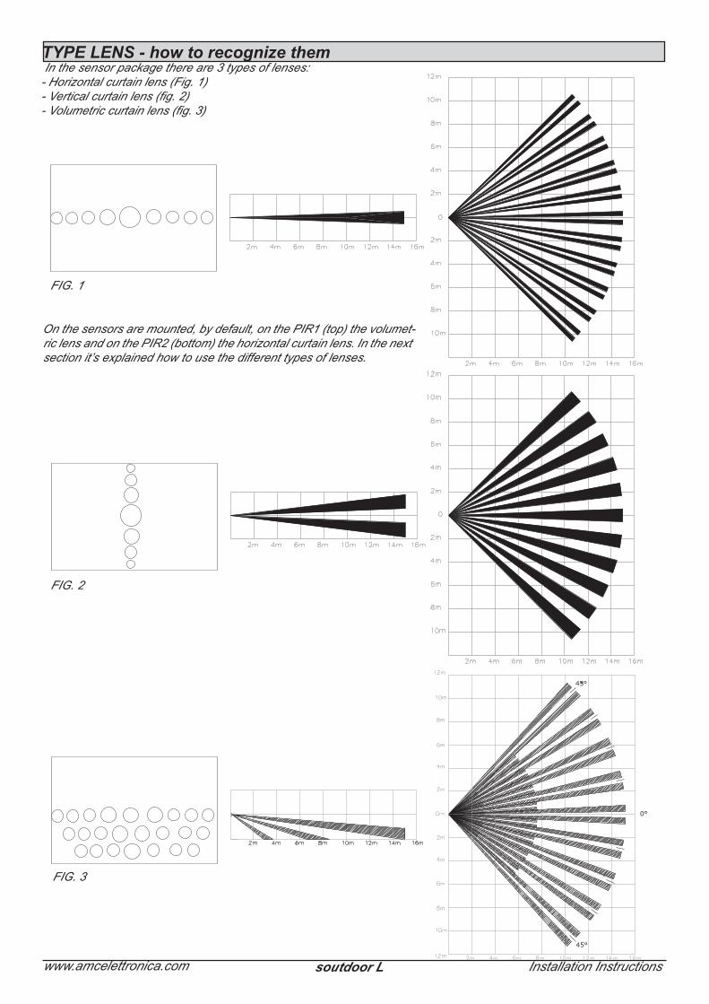
FIG. 1
FIG. 2
FIG. 3
TYPE LENS - how to recognize themIn the sensor package there are 3 types of lenses:
- Horizontal curtain lens (Fig. 1)- Vertical curtain lens (fig. 2)- Volumetric curtain lens (fig. 3)
On the sensors are mounted, by default, on the PIR1 (top) the volumet-ric lens and on the PIR2 (bottom) the horizontal curtain lens. In the next section it’s explained how to use the different types of lenses.

www.amcelettronica.com Installation Instructionssoutdoor L
1 2 3 4 5 6FUNCTIONS
1 2 3 4 5 6FUNCTIONS
1 2 3 4 5 6FUNCTIONS
1 2 3 4 5 6FUNCTIONS
Lenses providedThe lenses mounted on the sensor are: volumetric for PIR 1 (upper), horizontal curtain for PIR 2 with rather thick beams. This solution is designed for almost all applications that require a standard installation at about 1.8/2 meters high, with the possibility of managing the presence of animals. (fig. above)Besides the standard configuration, you can use the optional lenses included in the package.Using the sensor with 2 horizontal curtain lenses: you can position the sensor at a height between 80 cm and 1.2 m based on need. Then adjust the board position based on the beam range.This way you have a variable height protection from 35/40 cm from the ground and up to 1.6 cm high with a horizontal coverage of about 80/100 degrees. With this configuration you can achieve immunity to medium to large animals even at considerable distances (15 m).
Using the sensor with 2 vertical curtain lenses: the use of vertical curtain lenses is based on the need to protect doors and windows with a vertical curtain that is no wider than 50 cm. In this way the protection is only near the doors and/or windows without extending into other areas. You can position the sensor at a height of between 1 m and 2 m based on need. The beam is about 50 cm wide for an aperture of about 90/100 vertical degrees (fig. below)
1 2 3 4 5 6FUNCTIONS
The lenses are attached to the sensor with funnels that are snapped into the housings on the front cover (fig.)Replacing the lenses

www.amcelettronica.com Installation Instructionssoutdoor L
To replace the lenses you must remove the funnel and remove the lens that is resting in the housing as shown in figure 1 and 2.Note: the smooth part of the lenses must be positioned towards the outside.Important: the volumetric lens has one direction, therefore pay close attention to how it is positioned. When put up against the light you can see how the FRESNEL lenses work. They are always kept towards the bottom.
Position the new lens in the housing, replace the funnel and snap it into its housing.
2. instaLLationRemove the screws from the upper cover and then remove the board mounting screws.

www.amcelettronica.com Installation Instructionssoutdoor L
Remove the board, making a hole in the back of the upper cover for the cable to pass through in a suitable installation position. Make another 2 holes to attach the sensor to the wall. We recommend using anchors that are no smaller than 3 mm.
Once the cable and wall attachment holes have been made, take the measurement to attach an anchor (3 mm) to the anti-removal system. (see above fig.1 and fig.2)Then attach the bottom and re-close, taking into account the positioning mentioned previously.Note: remember that the distance between the board and the base is 13.5 mm. Space reserved for the proper positioning of the cable feeder or any piping to be inserted.
Screw for Anti-removal system - Fig.2
Using the bracketYou can use the bracket included in the package for attaching it to the wall. The back of the cover is ready for attach-ment of the bracket and for the passage of the cables inside it. You can see how it should be used in the figure. In case of use of the bracket, for the closure of the anti-removal tamper mount the specific screw, in the seat shown in Fig.1.
bracket
Screw for Anti-removal system - Fig.1
A B
C D
Bottom of the detector Detector + bracket

www.amcelettronica.com Installation Instructionssoutdoor L
SOUTDOORInput Voltage 0.5 to 13.8 VCurrent Drain (Alarm / Stand-By) 25 mA / 14 mA @ 13.8VCoverage 6/12 m Aperture Angle 90°2 PIR / Pyroelectric full digitalLens 1 Fresnel (22 Patterns on 3 levels)Lens 2 Fresnel horizontal curtain (11 Patterns 1 level)OPTIONAL Lens Fresnel, vertical (11 Patterns 11 level)Alarm period 2 sec.Anti-opening ✔Back Tamper ✔Alarm contact 0.2 A - 24 Vcc Tamper Switch Max 40 mA - 30 VccOperating Temperature From -30 °C to +55 °C
Storage Temperature From -30 °C to +60 °C RFI Protection 30 V / m (80 /1000 MHz)*Walk Test LED (MW and PIR) ✔Housing / Cover ABSDimensions 185 X 85 X 70 mm weight 265Gr
technicaL features
Installation must be performed according to accepted standards by specialized personnel.The manufacturer shall not be responsible if the product is tampered with by unauthorised persons. We recommend that you check the correct operation of the alarm system at least once per month. A reliable electronic alarm system does not prevent intrusions, robberies, fires or other occurrences but simply reduces the risk of occurrence.
Installation must be carried out following the local installation norms by qualified personnel. The manufacturer refuses any responsibility when changes or unauthorized repairs are made to the product/system.It is recommended to test the operation of the alarm product/system at least once a month. Despite frequent testing and due to, but not limited to, any or all of the following: tampering, electrical or communication disruption or improper use, it is possible for the product/system to fail to prevent burglary, rubbery, fire or otherwise. A properly installed and maintained alarm system can only reduce the risk that this happens.