dubai sea breeze - gekinvest.com · dubai sea breeze . production facilities . hddwrp “geyser”...
TRANSCRIPT
Hydraulic Drive for Deep Well Rod Pump
(HDDWRP) “GEYSER”
DUBAI SEA BREEZE
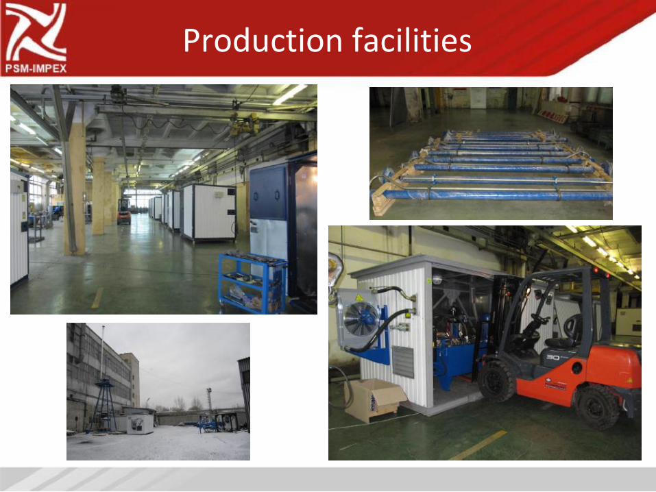
Production facilities
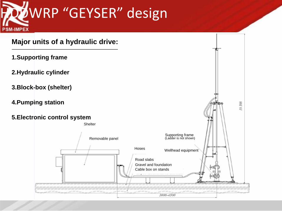
HDDWRP “GEYSER” design
Major units of a hydraulic drive:
1.Supporting frame
2.Hydraulic cylinder
3.Block-box (shelter)
4.Pumping station
5.Electronic control system
Shelter
Supporting frame Removable panel
Hoses
Road slabs
(Ladder is not shown)
Wellhead equipment
Gravel and foundation Cable box on stands
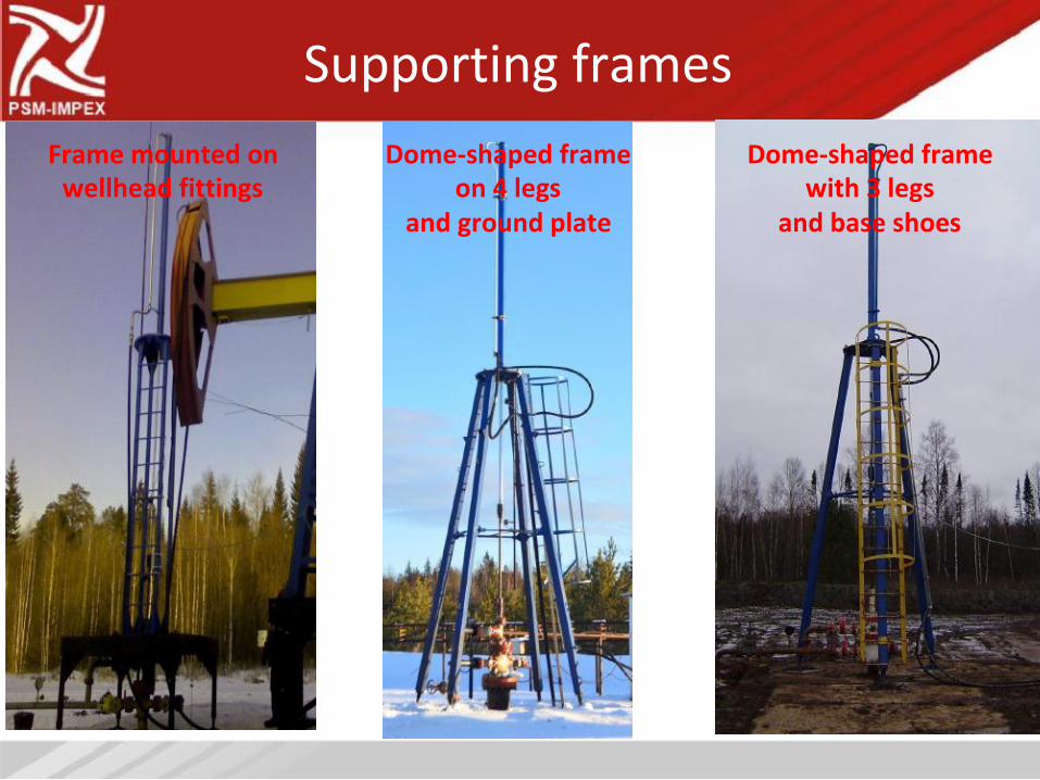
Supporting frames
Frame mounted on
wellhead fittings
Dome-shaped frame
on 4 legs
and ground plate
Dome-shaped frame
with 3 legs
and base shoes
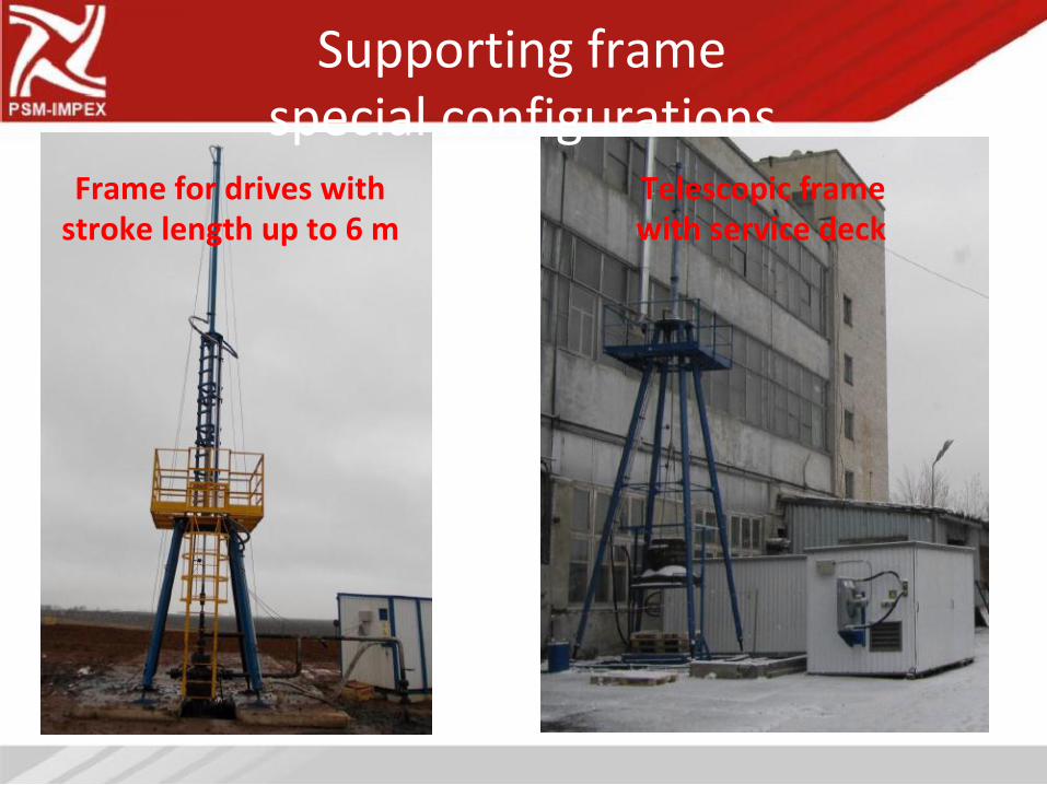
Supporting frame
special configurations
Frame for drives with
stroke length up to 6 m
Telescopic frame
with service deck
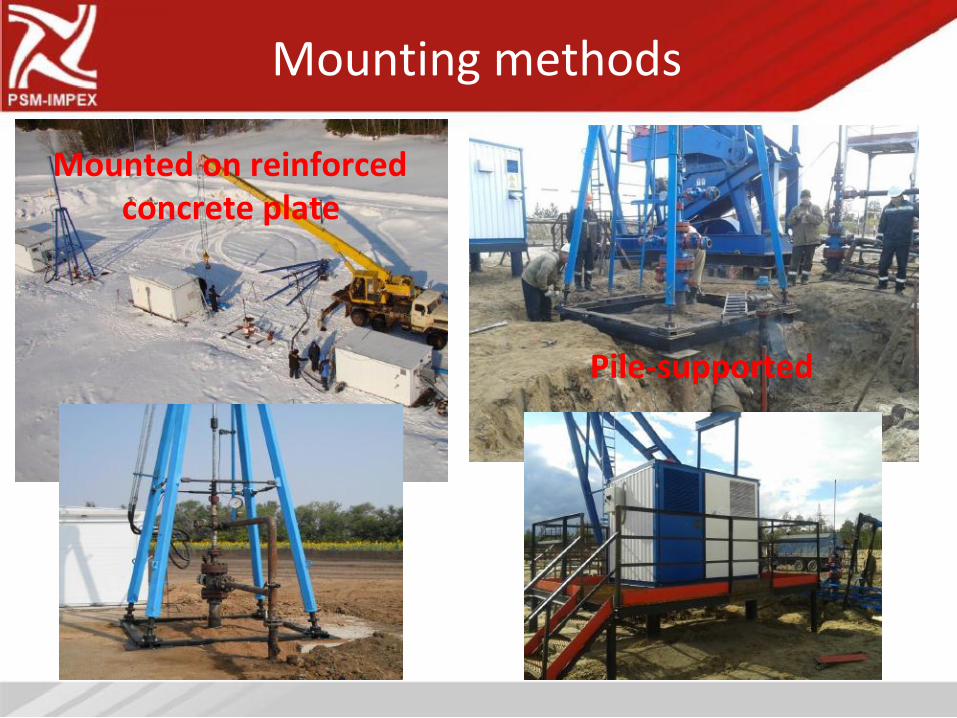
Mounting methods
Mounted on reinforced
concrete plate
Pile-supported
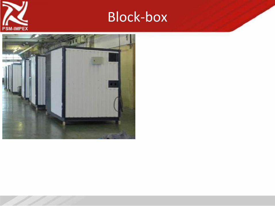
Block-box
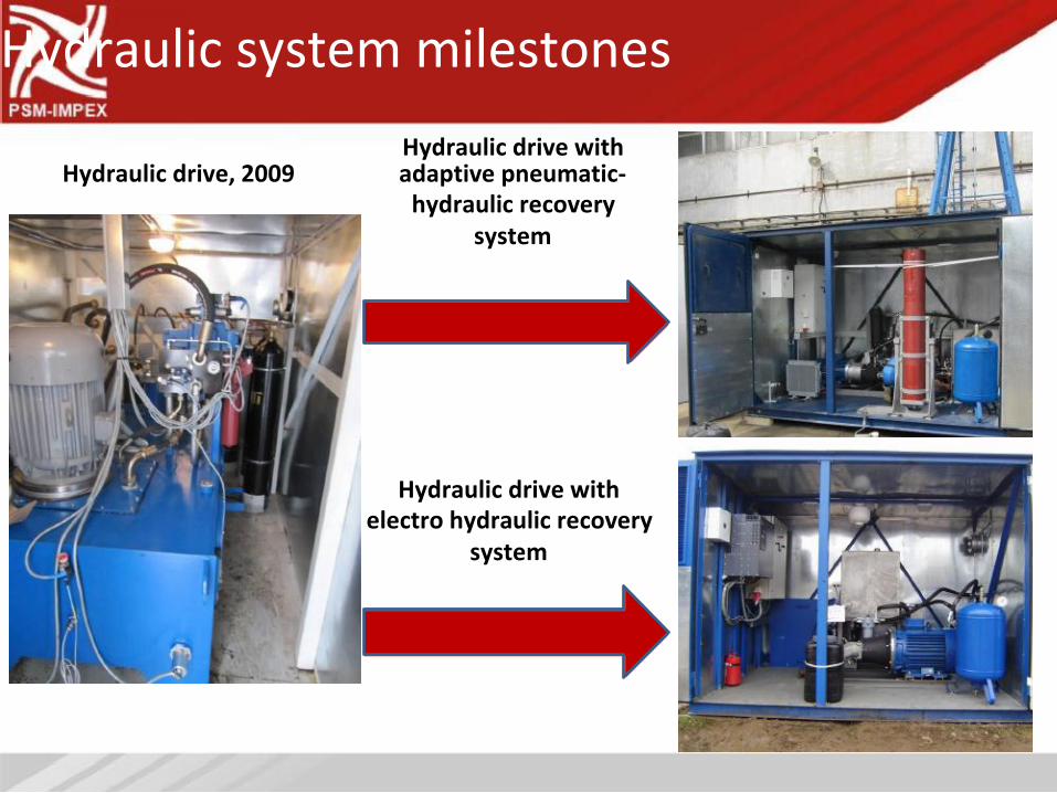
Hydraulic system milestones
Hydraulic drive with
Hydraulic drive, 2009 adaptive pneumatic-
hydraulic recovery
system
Hydraulic drive with
electro hydraulic recovery
system
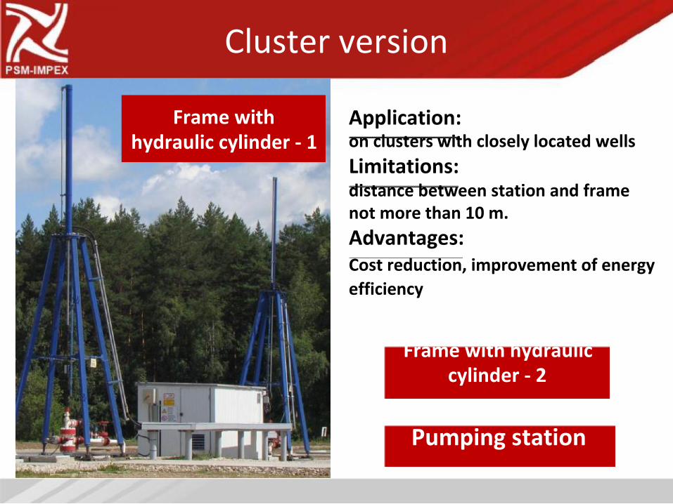
Cluster version
Frame with
hydraulic cylinder - 1
Application:
on clusters with closely located wells
Limitations:
distance between station and frame
not more than 10 m.
Advantages:
Cost reduction, improvement of energy
efficiency
Frame with hydraulic
cylinder - 2
Pumping station
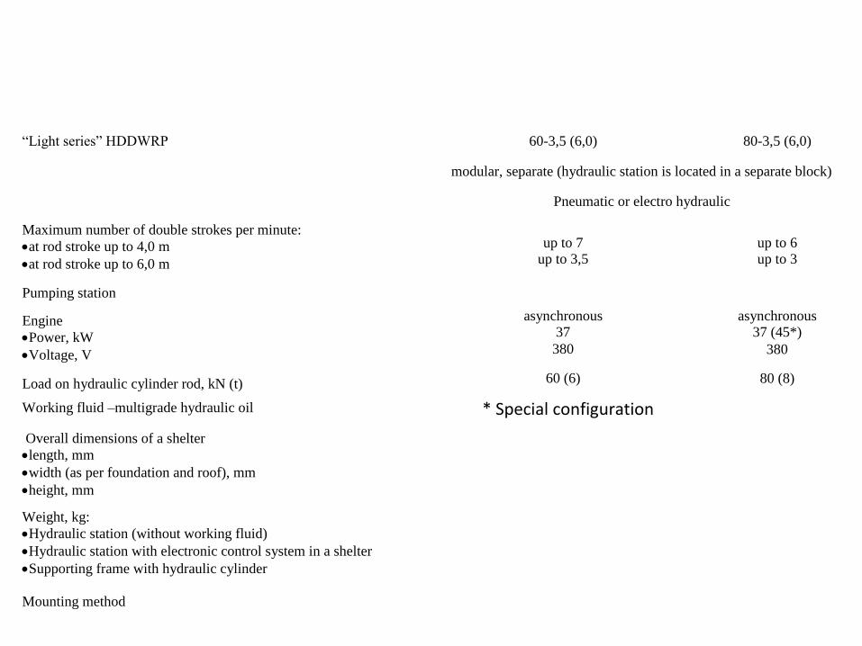
“Light series”
hydraulic drives “GEYSER”
“Light series” HDDWRP 60-3,5 (6,0) 80-3,5 (6,0)
modular, separate (hydraulic station is located in a separate block)
Pneumatic or electro hydraulic
Maximum number of double strokes per minute: at rod stroke up to 4,0 m
at rod stroke up to 6,0 m
Pumping station
Engine Power, kW
Voltage, V
Load on hydraulic cylinder rod, kN (t)
up to 7 up to 3,5
asynchronous 37
380
60 (6)
up to 6 up to 3
asynchronous 37 (45*)
380
80 (8)
Working fluid –multigrade hydraulic oil
Overall dimensions of a shelter length, mm
width (as per foundation and roof), mm
height, mm
Weight, kg: Hydraulic station (without working fluid)
Hydraulic station with electronic control system in a shelter
Supporting frame with hydraulic cylinder
Mounting method
* Special configuration
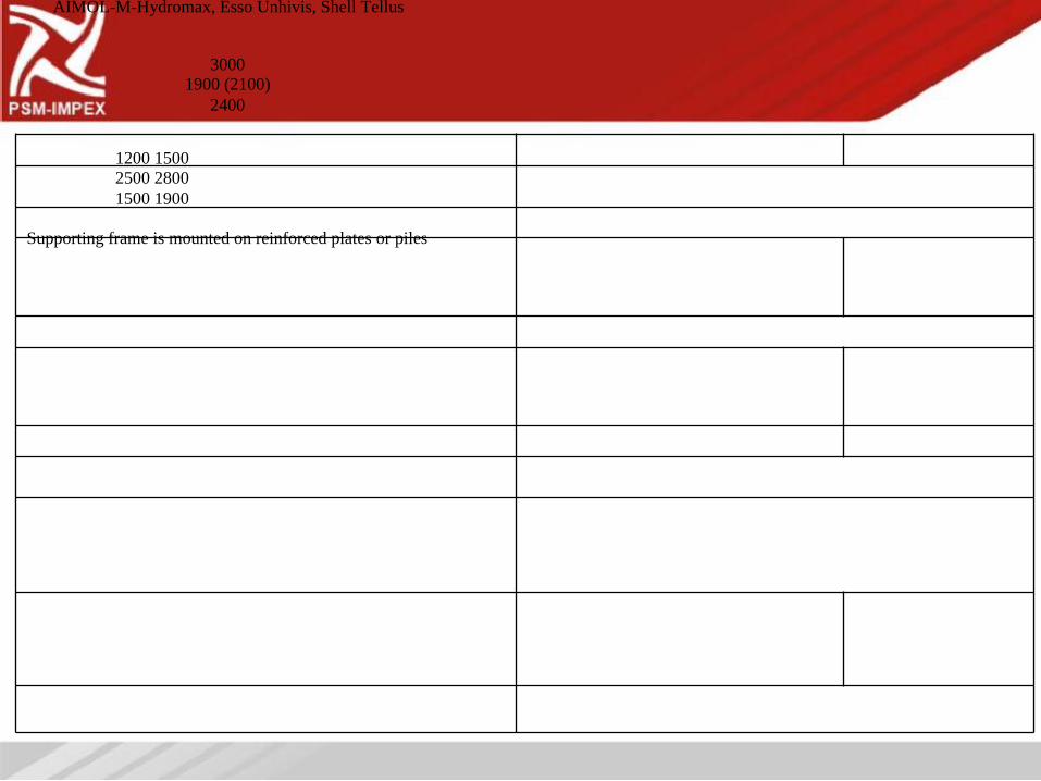
AIMOL-M-Hydromax, Esso Unhivis, Shell Tellus
3000 1900 (2100)
2400
1200 1500 2500 2800
1500 1900
Supporting frame is mounted on reinforced plates or piles
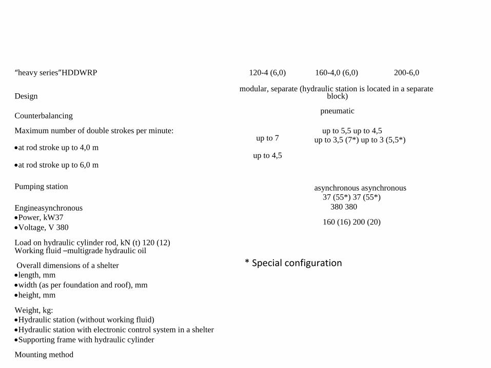
“Heavy series”
hydraulic drives “GEYSER”
“heavy series”HDDWRP 120-4 (6,0) 160-4,0 (6,0) 200-6,0
modular, separate (hydraulic station is located in a separate Design
Counterbalancing
Maximum number of double strokes per minute: up to 7
at rod stroke up to 4,0 m up to 4,5
at rod stroke up to 6,0 m
Pumping station
Engineasynchronous Power, kW37
Voltage, V 380
Load on hydraulic cylinder rod, kN (t) 120 (12)
block)
pneumatic
up to 5,5 up to 4,5 up to 3,5 (7*) up to 3 (5,5*)
asynchronous asynchronous 37 (55*) 37 (55*)
380 380
160 (16) 200 (20)
Working fluid –multigrade hydraulic oil
Overall dimensions of a shelter length, mm
width (as per foundation and roof), mm
height, mm
Weight, kg: Hydraulic station (without working fluid)
Hydraulic station with electronic control system in a shelter
Supporting frame with hydraulic cylinder
Mounting method
* Special configuration
AIMOL-M-Hydromax, Esso Unhivis, Shell Tellus
3000 1900 (2100)
2400
1200 1500 2000 2500 2800 4000
1500 1900 2500
Supporting frame is mounted on reinforced plates or piles
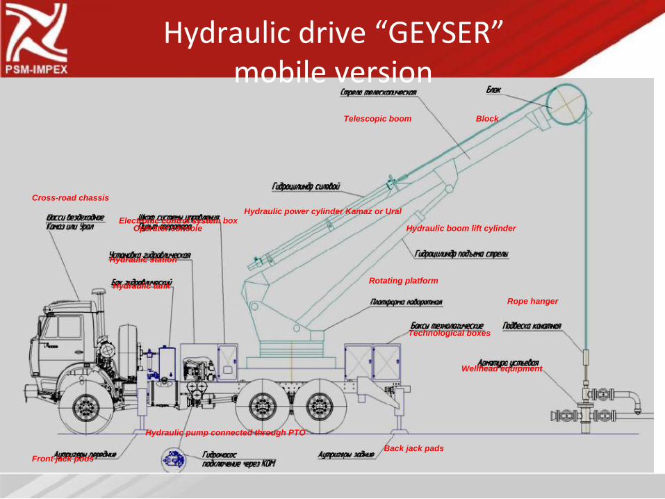
Hydraulic drive “GEYSER”
mobile version
Telescopic boom
Cross-road chassis
Hydraulic power cylinder Kamaz or Ural Electronic control system box
Block
Operator console
Hydraulic station
Hydraulic tank
Hydraulic pump connected through PTO
Front jack pods
Hydraulic boom lift cylinder
Rotating platform
Rope hanger
Technological boxes
Wellhead equipment
Back jack pads
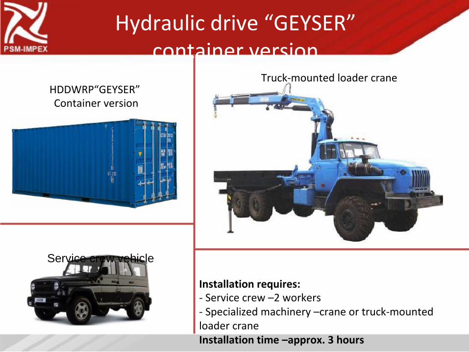
Hydraulic drive “GEYSER”
container version
Truck-mounted loader crane
HDDWRP“GEYSER”
Container version
Service crew vehicle
Installation requires: - Service crew –2 workers
- Specialized machinery –crane or truck-mounted
loader crane
Installation time –approx. 3 hours
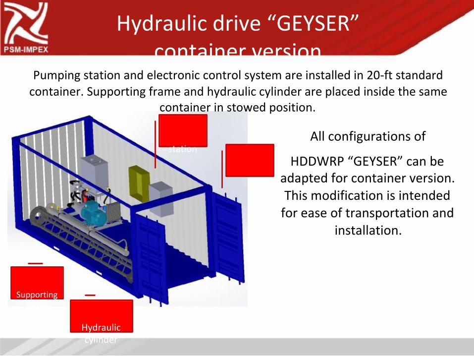
Hydraulic drive “GEYSER”
container version
Pumping station and electronic control system are installed in 20-ft standard
container. Supporting frame and hydraulic cylinder are placed inside the same
container in stowed position.
All configurations of
station
HDDWRP “GEYSER” can be
adapted for container version.
This modification is intended
for ease of transportation and
installation.
Supporting
frame
Hydraulic
cylinder
Hydraulic drive “GEYSER”
mobile version
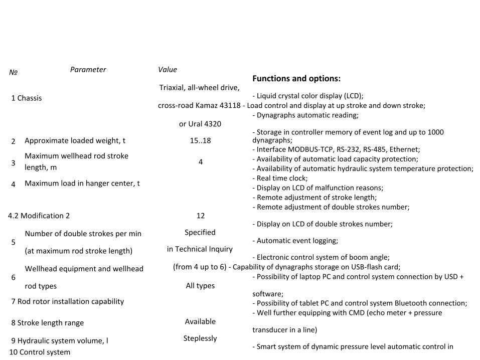
№
1 Chassis
Parameter Value Functions and options:
Triaxial, all-wheel drive, - Liquid crystal color display (LCD);
cross-road Kamaz 43118 - Load control and display at up stroke and down stroke;
- Dynagraphs automatic reading; or Ural 4320
- Storage in controller memory of event log and up to 1000 2
3
4
Approximate loaded weight, t
Maximum wellhead rod stroke
length, m
Maximum load in hanger center, t
15..18
4
dynagraphs; - Interface MODBUS-TCP, RS-232, RS-485, Ethernet;
- Availability of automatic load capacity protection;
- Availability of automatic hydraulic system temperature protection;
- Real time clock;
- Display on LCD of malfunction reasons;
- Remote adjustment of stroke length;
- Remote adjustment of double strokes number; 4.2 Modification 2
Number of double strokes per min 5
(at maximum rod stroke length)
Wellhead equipment and wellhead 6
rod types
7 Rod rotor installation capability
8 Stroke length range
9 Hydraulic system volume, l
10 Control system
12 - Display on LCD of double strokes number;
Specified - Automatic event logging;
in Technical Inquiry - Electronic control system of boom angle;
(from 4 up to 6) - Capability of dynagraphs storage on USB-flash card;
- Possibility of laptop PC and control system connection by USD + All types
software; - Possibility of tablet PC and control system Bluetooth connection;
- Well further equipping with CMD (echo meter + pressure Available
transducer in a line) Steplessly
- Smart system of dynamic pressure level automatic control in
from 0,2 m up to 4,0 m annular space;
- GSM-Module. 300
Electronic
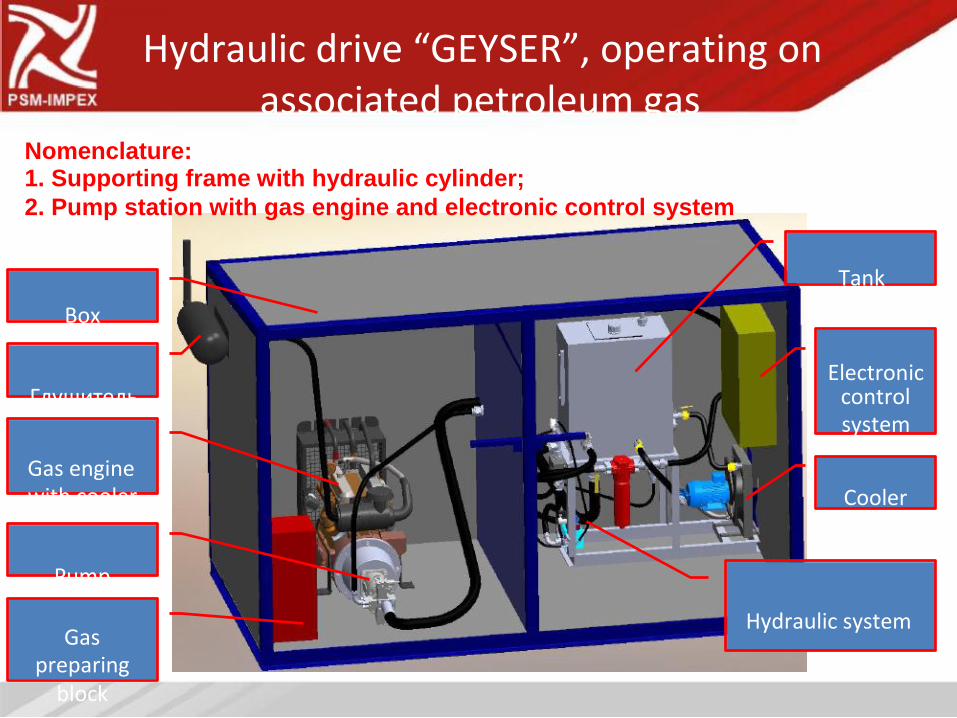
Hydraulic drive “GEYSER”, operating on
associated petroleum gas
Nomenclature:
1. Supporting frame with hydraulic cylinder;
2. Pump station with gas engine and electronic control system
Tank
Box
Electronic
Глушитель
Gas engine
with cooler
Pump
Gas
preparing
block
control
system
Cooler
Hydraulic system
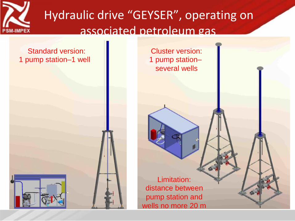
Hydraulic drive “GEYSER”, operating on
associated petroleum gas
Standard version:
1 pump station–1 well
Cluster version:
1 pump station–
several wells
Limitation:
distance between
pump station and
wells no more 20 m
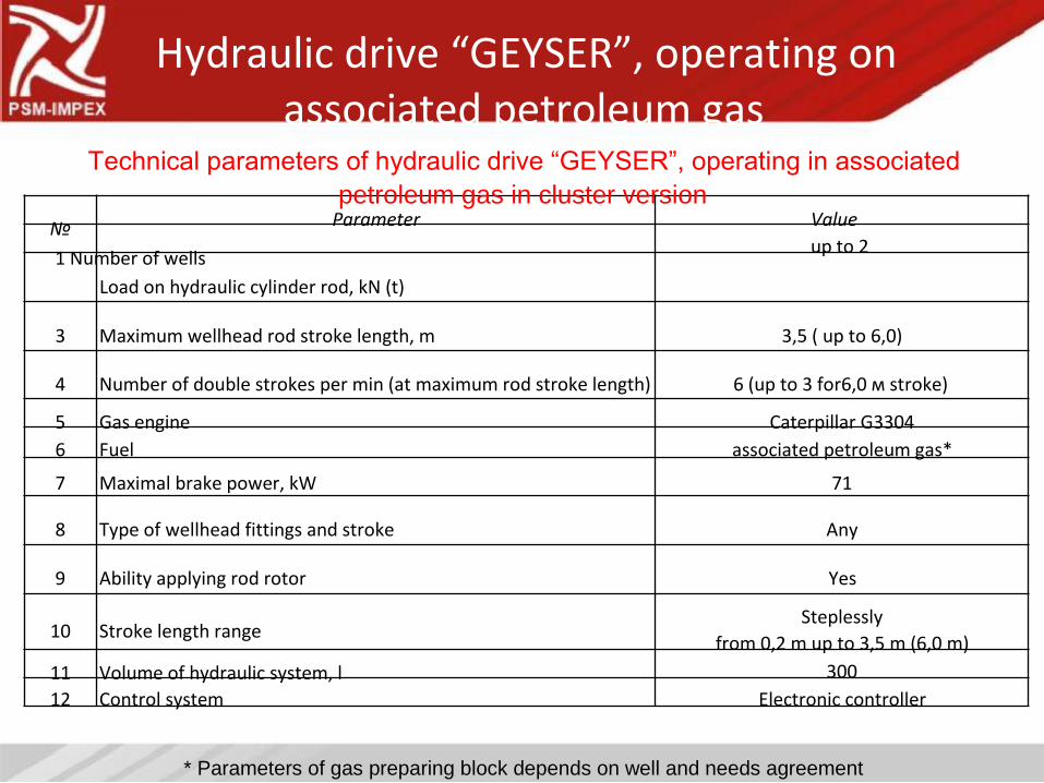
Hydraulic drive “GEYSER”, operating on
associated petroleum gas
Technical parameters of hydraulic drive “GEYSER”, operating in associated
petroleum gas in cluster version
№
1 Number of wells
Parameter Value
up to 2
Load on hydraulic cylinder rod, kN (t)
3
4
5
6
7
8
9
10
11
12
Maximum wellhead rod stroke length, m
Number of double strokes per min (at maximum rod stroke length)
Gas engine
Fuel
Maximal brake power, kW
Type of wellhead fittings and stroke
Ability applying rod rotor
Stroke length range
Volume of hydraulic system, l
Control system
3,5 ( up to 6,0)
6 (up to 3 for6,0 м stroke)
Caterpillar G3304
associated petroleum gas*
71
Any
Yes
Steplessly
from 0,2 m up to 3,5 m (6,0 m)
300
Electronic controller
* Parameters of gas preparing block depends on well and needs agreement
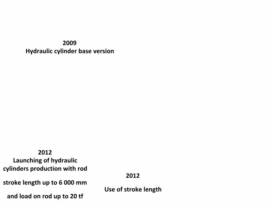
Evolution of
Hydraulic cylinders
2009
Hydraulic cylinder base version
2012
Launching of hydraulic
cylinders production with rod
2012
stroke length up to 6 000 mm
Use of stroke length
and load on rod up to 20 tf
analog sensors
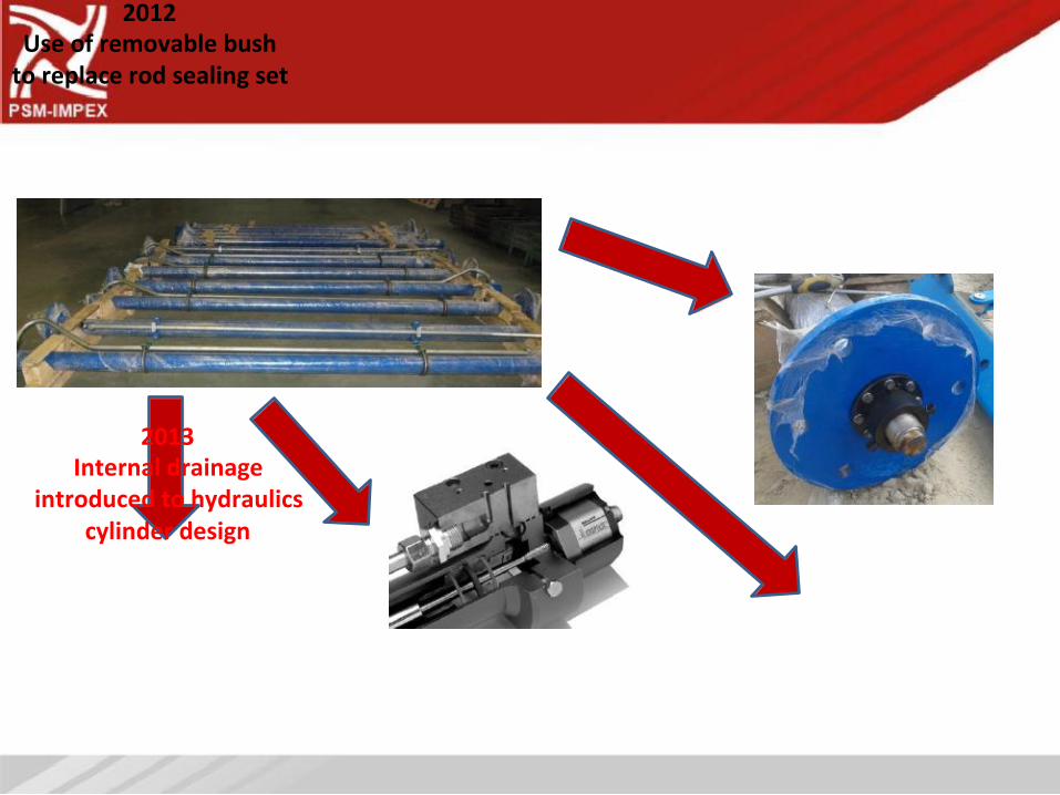
2012
Use of removable bush
to replace rod sealing set
2013
Internal drainage
introduced to hydraulics
cylinder design
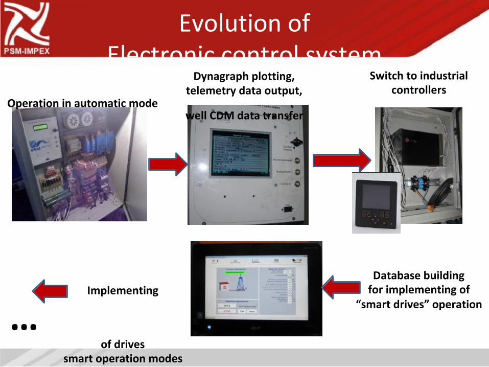
Evolution of
Electronic control system
Dynagraph plotting,
telemetry data output,
Operation in automatic mode
well CDM data transfer
Implementing
…
of drives
smart operation modes
Switch to industrial
controllers
Database building
for implementing of
“smart drives” operation
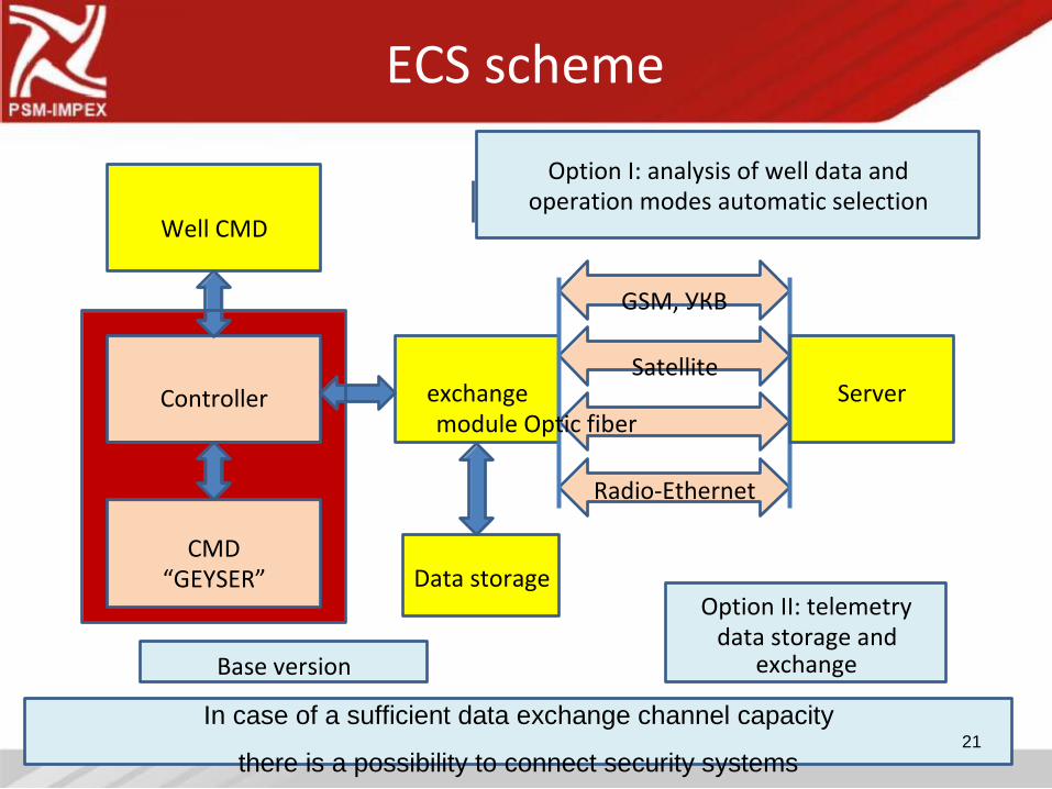
ECS scheme
Option I: analysis of well data and
operation modes automatic selection
Well CMD
GSM, УКВ
Satellite
Controller
CMD
“GEYSER”
exchange
module Optic fiber
Radio-Ethernet
Data storage
Server
Option II: telemetry
data storage and
Base version exchange
In case of a sufficient data exchange channel capacity
21
there is a possibility to connect security systems
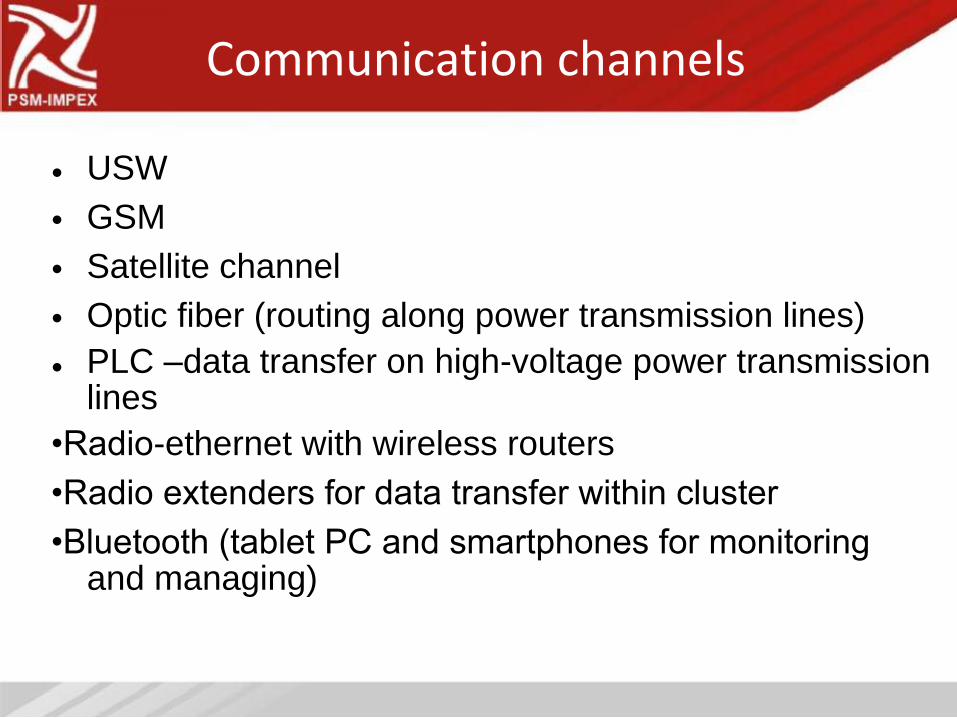
Communication channels
•
•
•
•
•
USW
GSM
Satellite channel
Optic fiber (routing along power transmission lines)
PLC –data transfer on high-voltage power transmission
lines
•Radio-ethernet with wireless routers
•Radio extenders for data transfer within cluster
•Bluetooth (tablet PC and smartphones for monitoring
and managing)
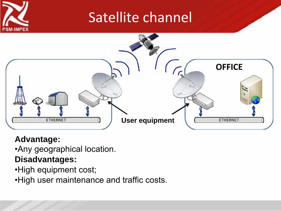
Satellite channel
OFFICE
User equipment
Advantage:
•Any geographical location.
Disadvantages:
•High equipment cost;
•High user maintenance and traffic costs.
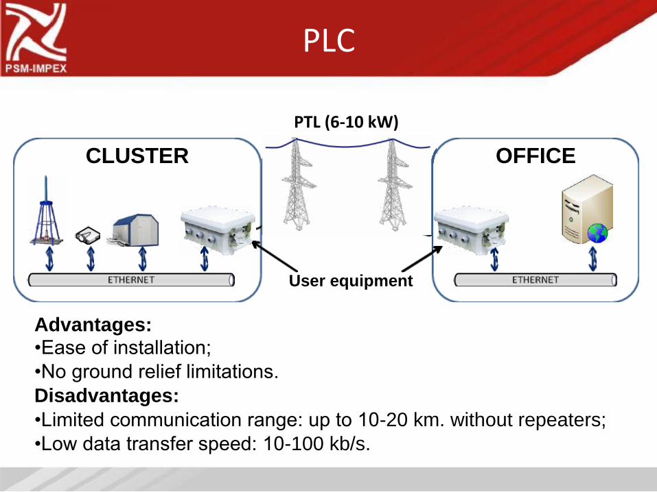
PLC
PTL (6-10 kW)
CLUSTER
User equipment
Advantages:
•Ease of installation;
•No ground relief limitations.
Disadvantages:
OFFICE
•Limited communication range: up to 10-20 km. without repeaters;
•Low data transfer speed: 10-100 kb/s.
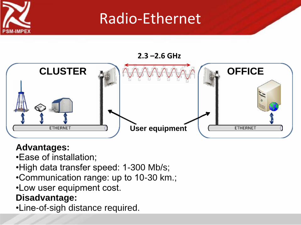
Radio-Ethernet
2.3 –2.6 GHz
CLUSTER
User equipment
Advantages:
•Ease of installation;
•High data transfer speed: 1-300 Mb/s;
•Communication range: up to 10-30 km.;
•Low user equipment cost.
Disadvantage:
•Line-of-sigh distance required.
OFFICE
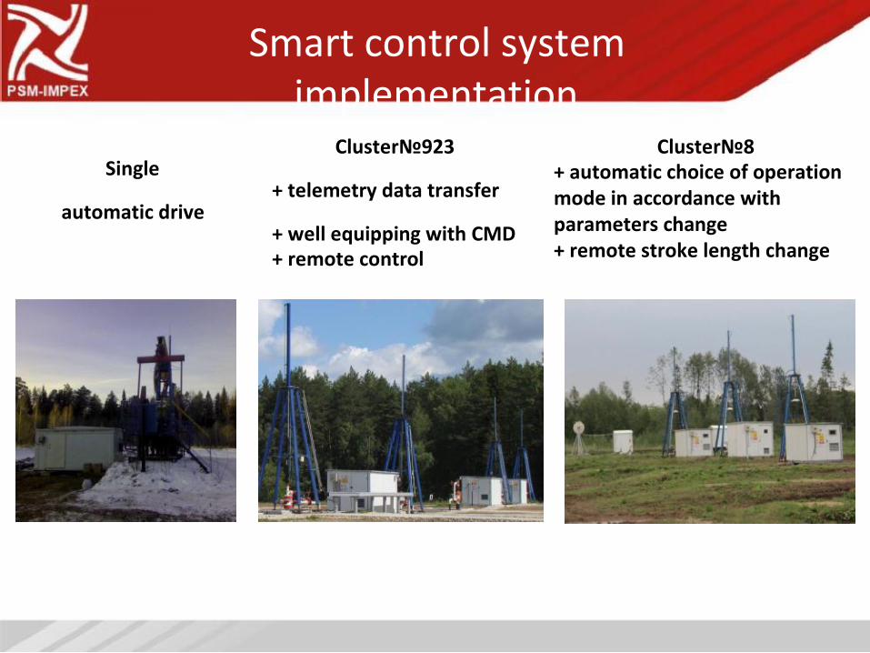
Smart control system
implementation
Cluster№923
Single
+ telemetry data transfer
automatic drive
+ well equipping with CMD
+ remote control
Cluster№8
+ automatic choice of operation
mode in accordance with
parameters change
+ remote stroke length change
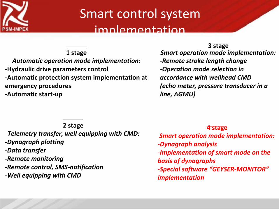
Smart control system
implementation
3 stage
1 stage
Automatic operation mode implementation: -Hydraulic drive parameters control
-Automatic protection system implementation at
emergency procedures
-Automatic start-up
2 stage
Telemetry transfer, well equipping with CMD:
-Dynagraph plotting
-Data transfer
-Remote monitoring
-Remote control, SMS-notification
-Well equipping with CMD
Smart operation mode implementation:
-Remote stroke length change
-Operation mode selection in
accordance with wellhead CMD
(echo meter, pressure transducer in a
line, AGMU)
4 stage
Smart operation mode implementation: -Dynagraph analysis
-Implementation of smart mode on the
basis of dynagraphs
-Special software “GEYSER-MONITOR”
implementation
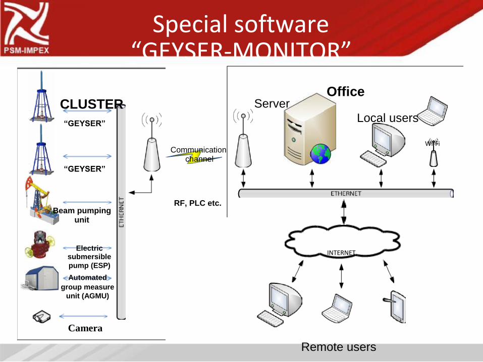
Special software
“GEYSER-MONITOR”
Office
CLUSTER
“GEYSER”
Communication channel
“GEYSER”
RF, PLC etc. Beam pumping
unit
Electric
submersible pump (ESP)
Automated
group measure unit (AGMU)
Camera
Server
Local users
Wi-Fi
INTERNET
Remote users
System features
•Web –interface;
• Designed for HDDWRP “GEYSER”and
applicable well CMD;
•Self adjustment of user interface in accordance
with configuration of equipment connected;
•System coat is determined by the number of
equipment connected.
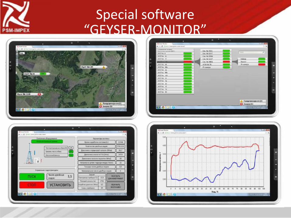
Special software
“GEYSER-MONITOR”
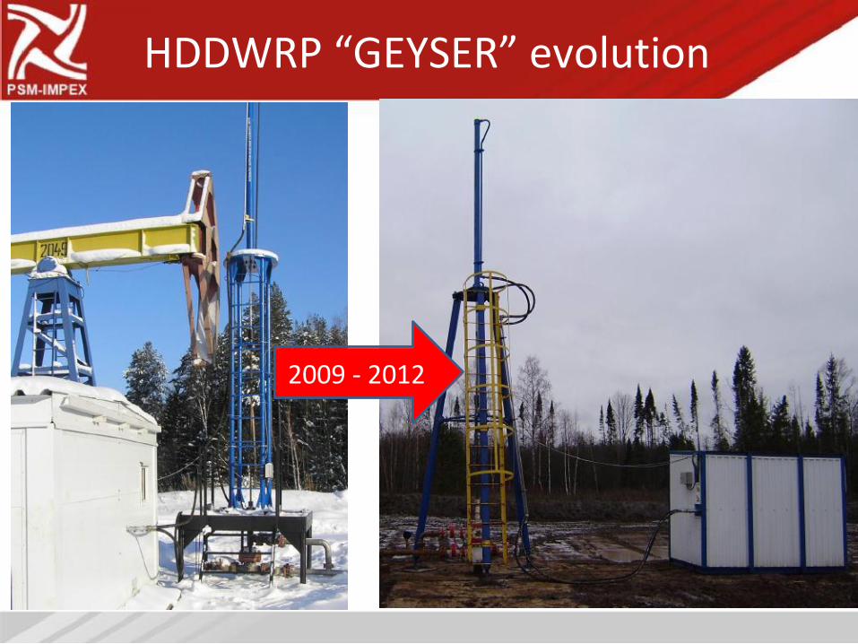
HDDWRP “GEYSER” evolution
2009 - 2012
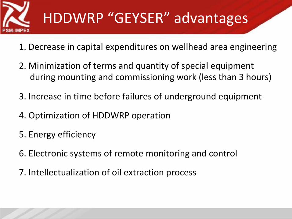
HDDWRP “GEYSER” advantages
1. Decrease in capital expenditures on wellhead area engineering
2. Minimization of terms and quantity of special equipment
during mounting and commissioning work (less than 3 hours)
3. Increase in time before failures of underground equipment
4. Optimization of HDDWRP operation
5. Energy efficiency
6. Electronic systems of remote monitoring and control
7. Intellectualization of oil extraction process
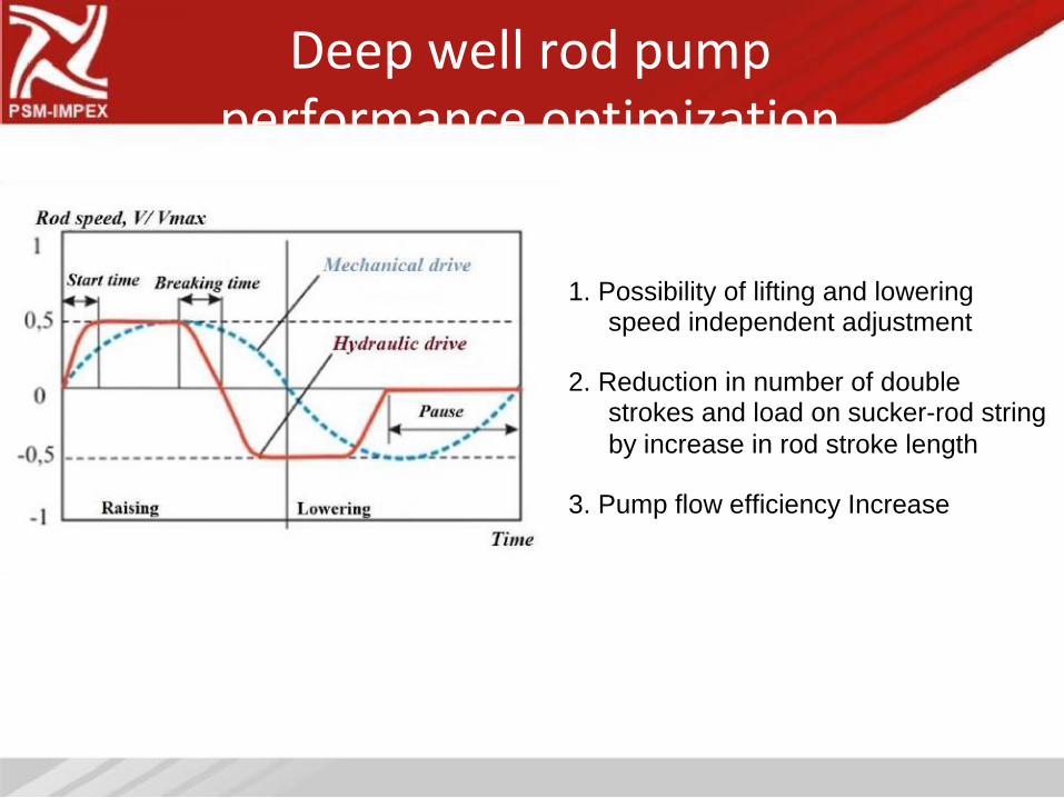
Deep well rod pump
performance optimization
1. Possibility of lifting and lowering
speed independent adjustment
2. Reduction in number of double
strokes and load on sucker-rod string
by increase in rod stroke length
3. Pump flow efficiency Increase
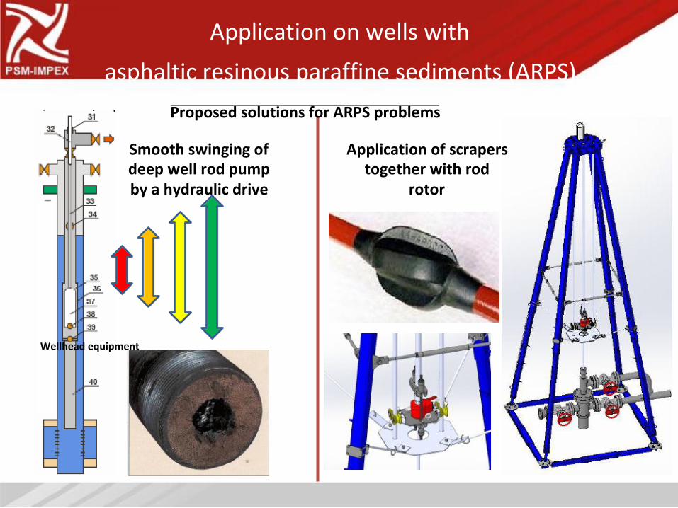
Application on wells with
asphaltic resinous paraffine sediments (ARPS)
Proposed solutions for ARPS problems
Smooth swinging of
deep well rod pump
by a hydraulic drive
Wellhead equipment
Application of scrapers
together with rod
rotor
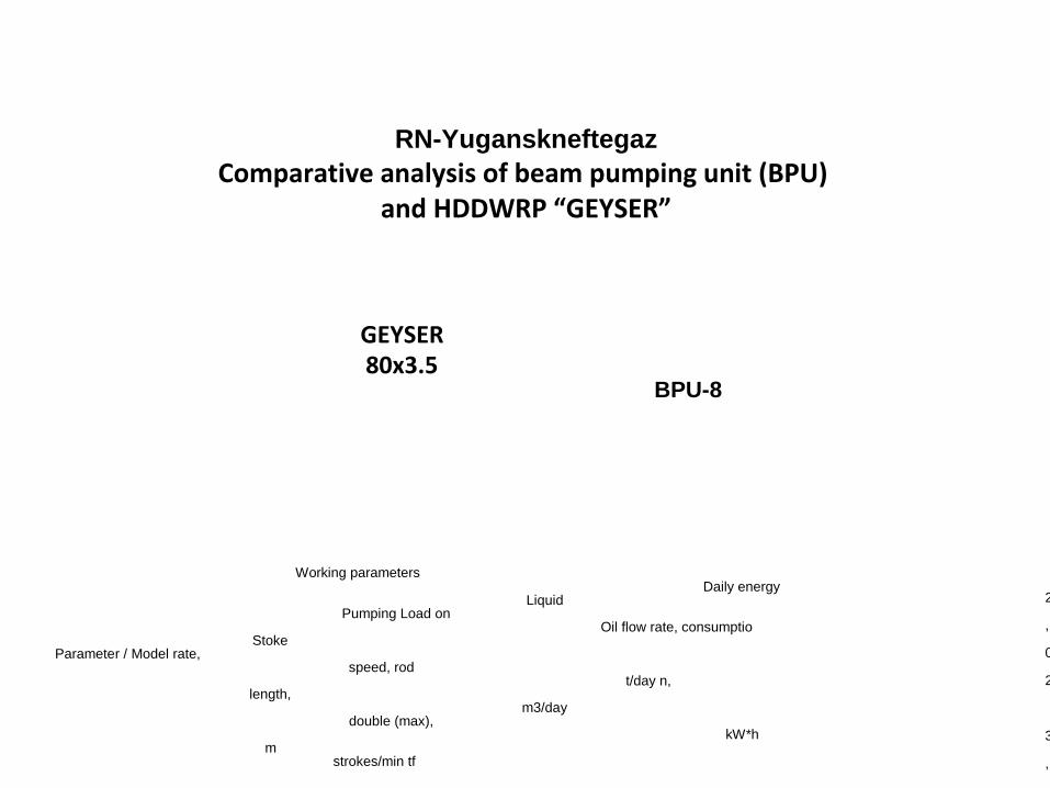
Energy efficiency increase
RN-Yuganskneftegaz
Comparative analysis of beam pumping unit (BPU)
and HDDWRP “GEYSER”
GEYSER
80x3.5
BPU-8
Working parameters
Daily energy Liquid
Pumping Load on Oil flow rate, consumptio
Stoke Parameter / Model rate,
speed, rod t/day n,
length, m3/day
double (max), kW*h
m strokes/min tf
2
,
0
2
3
,
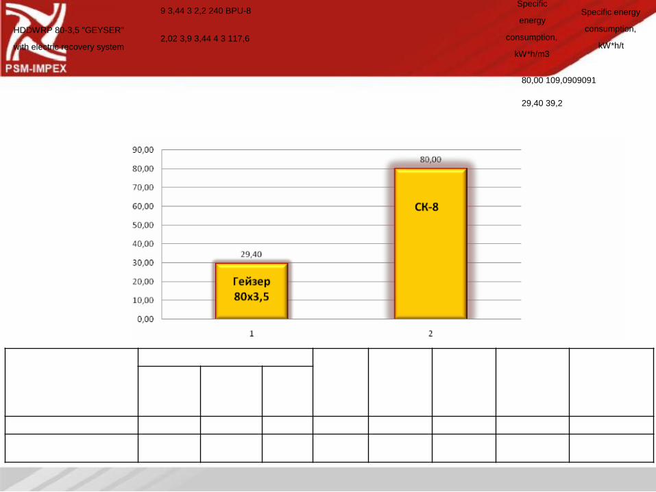
9 3,44 3 2,2 240 BPU-8 HDDWRP 80-3,5 "GEYSER"
2,02 3,9 3,44 4 3 117,6 with electric recovery system
Specific Specific energy
energy consumption,
consumption, kW*h/t
kW*h/m3
80,00 109,0909091
29,40 39,2
Energy efficiency increase
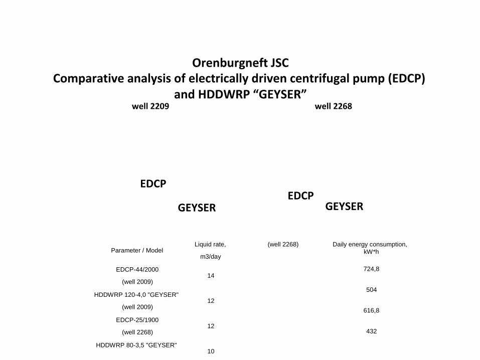
Orenburgneft JSC
Comparative analysis of electrically driven centrifugal pump (EDCP)
and HDDWRP “GEYSER”
well 2209
EDCP
EDCP
GEYSER
well 2268
GEYSER
Liquid rate,
Parameter / Model m3/day
EDCP-44/2000
14 (well 2009)
HDDWRP 120-4,0 "GEYSER"
12 (well 2009)
EDCP-25/1900
12 (well 2268)
HDDWRP 80-3,5 "GEYSER"
10
(well 2268) Daily energy consumption, kW*h
724,8
504
616,8
432
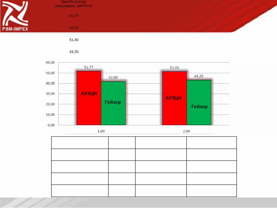
Specific energy consumption, kW*h/m3
51,77
42,00
51,40
43,20
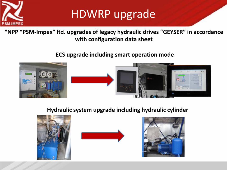
HDWRP upgrade
“NPP “PSM-Impex” ltd. upgrades of legacy hydraulic drives “GEYSER” in accordance
with configuration data sheet
ECS upgrade including smart operation mode
Hydraulic system upgrade including hydraulic cylinder
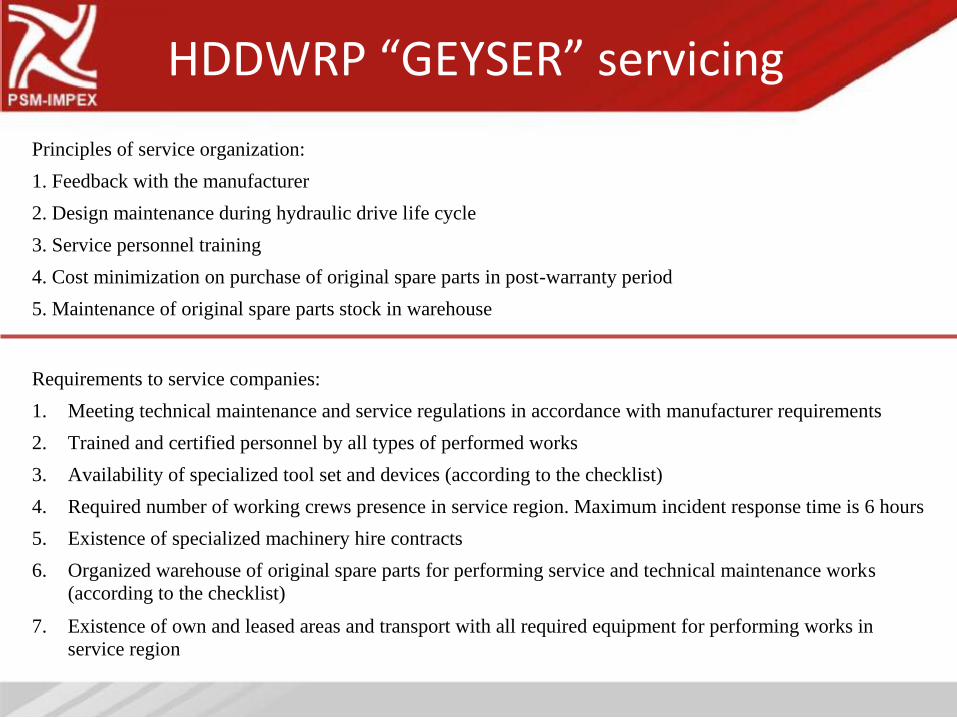
HDDWRP “GEYSER” servicing
Principles of service organization:
1. Feedback with the manufacturer
2. Design maintenance during hydraulic drive life cycle
3. Service personnel training
4. Cost minimization on purchase of original spare parts in post-warranty period
5. Maintenance of original spare parts stock in warehouse
Requirements to service companies:
1.
2.
3.
4.
5.
6.
7.
Meeting technical maintenance and service regulations in accordance with manufacturer requirements
Trained and certified personnel by all types of performed works
Availability of specialized tool set and devices (according to the checklist)
Required number of working crews presence in service region. Maximum incident response time is 6 hours
Existence of specialized machinery hire contracts
Organized warehouse of original spare parts for performing service and technical maintenance works
(according to the checklist)
Existence of own and leased areas and transport with all required equipment for performing works in
service region

Industrial safety behavior
1. Availability of permit documentation:
- Certificate of adequacy C-RU.AB75.B.00066
- Permit to use№ РРС00-23886
2. System shutdown for reasons:
- high load on polished rod
- high pressure
- hydraulics fluid and engine overheating
- voltage variation and electrical imbalance
3. Use of incombustible thermoinsulation materials in a
block-box
4. Availability of automatic fire fighting system
Global Engineering
General Trading and Contracting Co.
جـلــوبـال الـهـنـدســـــيـة
للتجــارة العـامـة والمقـاوالت
P.O. Box. 2880 - Salmiya, 22029 - Kuwait, 9th Floor, Al-Shrooq Tower, Jaber Al-Mubarak Street, Sharq, Kuwait
Tel : +965 22476953/4, Fax : +965 22476955,