dunkermotoren ac motors - motionusa - your source for · pdf file2 foreword / vorwort to our...
TRANSCRIPT

AC-MotorsWechselstrom-/Drehstrommotoren
Series KD/DR Baureihe KD/DR
DIN EN ISO 9001:2008
DIN EN ISO 14001:2004
COMPANY OF THE YEAR
2
Foreword / Vorwort
To Our Valued Customers,
Dunkermotoren is a world class leader in high quality motion control solutions to meet the ever increasing demands for cost effective and reliable drive solutions. Our comprehensive product range offers the flexibility to provide customized solutions as well as standardized components. The catalog represents Dunkermotoren´s years of engineering excellence.
The Dunkermotoren Team will continue to utilize our outstanding engineering and industrial capabilities to meet the requirements helping you to succeed. Wishing you great success in your business. Nikolaus GräfGeneral Manager
Liebe Kunden,
als führender Hersteller der Antriebstechnik bieten wir Ihnen wirtschaftliche, effiziente und qualitativ hochwertige Komplettlösungen.
Unser umfassendes Produkt- und Leistungsspektrum ermöglicht Ihnen ein hohes Maß an Flexibilität: Ob standardisierte Komponenten oder kundenspezifische Anforderungen – bei uns finden Sie garantiert die passende Lösung.
Mit diesem Katalog können Sie sich einen Überblick über unsere innovativen und richtungsweisenden Produkte verschaffen.
Das Dunkermotoren-Team berät Sie gerne engagiert und kompetent. Denn: Ihr Erfolg ist unser Ziel.
In diesem Sinne freuen wir uns auf Sie und wünschen Ihnen alles Gute.
Ihr Nikolaus GräfGeneral Manager

3
Content / Inhalt
2 Foreword / Vorwort
3 Content / Inhalt
4 Why Dunkermotoren? / Gute Gründe
6 Our Product Range / Unser modulares Lieferprogramm
7 Applications / Anwendungen
8 KD / DR Selection Guide / KD / DR Auswahlübersicht
8 Technical Information / Technische Informationen
10 KD/DR 52.1, 10 - 22 W
12 KD/DR 62.1, 34 - 44 W
14 KD/DR 52.1 / 62.1, 5 -15 W
16 KD/DR 52.0, 19 - 30 W
18 KD/DR 62.0, 36 - 87 W
20 KD/DR 62.0, 14 - 31 W
22 Brake Motors / Bremsmotoren
Gears / Getriebe
24 PLG 52
26 PLG 52 H
28 PLG 63
30 PLG 75
32 SG 62
34 SG 80
36 SG 120
40 Representatives and Distributors / Vertretungen
© 09/2010
Dunkermotoren GmbH
Printed in Germany

4
Why Dunkermotoren? / Gute Gründe
Technology & Customer Focus
At Dunkermotoren, research and develop-ment is a way of life. The company is actively committed to develop key technologies and products that are crucial for its growth. Next-generation technology is in the R&D pipeline today. Product development is focused on innova-tions to help our customers create value and differentiate themselves from competitors.
Innovation und Kundenorientierung
Dunkermotoren ist stolz darauf, vielfach neue Industrie-Standards in der Antriebsbranche geschaffen zu haben. Es ist der Anspruch eines Technologieführers, der Konkurrenz immer einen entscheidenden Schritt voraus zu sein.
Unsere innovativen marktorientierten Antriebslösungen machen unsere Kunden noch erfolgreicher und helfen ihnen, sich mit ihren Produkten positiv von denen der Mitbewerber abzusetzen.
Quality Assurance & Reliability
One of Dunkermotoren´s primary objectives is to offer outstanding quality. In 1991 Dunkermotoren became the world´s first manufacturers of small motors to be certified to ISO 9001. In the meantime, Dunkermotoren has won numerous quality awards.Dunkermotoren regards quality as a compre-hensive process involving all activities in the factory. Our products are manufactured in Germany and China on highly automated production lines. Failure mode and effects analysis during design and development, and fully automated testing integrated in the production line ensure a uniformly high level of quality.
Qualität & Zuverlässigkeit
Antriebslösungen höchster Qualität sind bei Dunkermotoren eine Selbstverständlichkeit, fest verankert in Unternehmensgrundsätzen und Philosophie. Bereits 1991 wurde Dunker-motoren als weltweit erster Hersteller von Kleinmotoren nach ISO 9001 zertifiziert. In der Zwischenzeit folgten zahlreiche weitere Auszeichnungen und Zertifizierungen von Kunden und Vereinigungen.Dunkermotoren versteht Qualität als einen ganzheitlichen Prozess, der sämtliche betrieb- liche Tätigkeiten umfasst. Dunkermotoren produziert in Deutschland und China; hochautomatisierte Fertigungsstrecken und vollautomatische Qualitätskontrollen in den Fertigungslinien gewährleisten ein konstant hohes Qualitätsniveau.
Flexibility, Delivery Performance & Complete Motion Solutions
Standardized motors, gears and modular accessories are available with a higher degree of flexibility to address specific requirements in complete motion solutions. For the customer, this means better control of quality, reduced inventory and reduced production time. If any detail does not entirely meet your requirements, our R&D department will make modifications at short notice. Dunkermotoren’s Modular System an optimized logistics, enables prompt delivery for both stock and customized products. Delivery time for stock items is 2-5 days and for customized solutions is 3-7 weeks.
Flexibilität, Lieferperformance und umfassende Antriebslösungen
Dunkermotoren´s Produktpalette ist so aufgebaut, dass sich mit standardisierten Motoren und einem modular aufgebauten Zubehör eine hohe Flexibilität für umfassende Antriebslösungen ergibt. Und sollten Sie einmal ein Produkt benötigen, das es noch nicht gibt, dann entwickelt unsere Konstruktionsabteilung kundenspezifische Sonderlösungen in kürzester Zeit.
Aufgrund der konsequenten Verwirklichung des Baukastensystems und einer ausge-klügelten Produktionslogistik bietet Dunker-motoren eine bessere Lieferperformance als die meisten Mitbewerber, bei Lagerprodukten (Ø 2-5 Tage) wie auch bei kundenspezifischen Lösungen (Ø 3-7 Wochen).

5
Service & Proximity
Whether home or abroad, Dunkermotoren´s multi-lingual customer service advisers are always on hand. By worldwide local presence of Dunkermotoren individual responsibility is given to the interests of the trading partners - the best drive solution and the most econo-mical application.
Today and in the future, Dunkermotoren will provide a total service to the customers - wherever they are.
Service & Kundennähe
Ob im In- oder Ausland, Dunkermotoren´s Kundenberater sind immer vor Ort präsent und sprechen die Sprache des Kunden. Zur bestmöglichen Berücksichtigung der Interessen des Kunden werden individuelle Schulungen, Betreuung und Beratung durch unsere hochkompetenten Account Manager gewährleistet.
In der Technik wie auch im Vertrieb - Dunkermotoren´s Mitarbeiter scheuen keine Herausforderung, Ihre Anforderungen und Wünsche sind Maßstab für Denken und Handeln.
Sustainable Development
Dunkermotoren is fully aware of its role to promote sustainable development. Therefore it commits itself to pay particular attention to the environment conservation while selecting and using efficiently raw materials and energy necessary for production, supply and use of the product.
In 2002 Dunkermotoren has introduced the environmental management system conforming to the standard ISO 14001.
Umweltschutz und nachhaltige Entwicklung
Dunkermotoren ist sich seiner Rolle, nachhaltige Entwicklung zu fördern, bewusst. Deshalb hat sich die Firma dem Umweltschutz verpflichtet. Ressourcen werden sparsam und effizient eingesetzt.
Als erster Hersteller von Elektrokleinmotoren erhielt Dunkermotoren im Jahre 2002 die Umweltmanagementauszeichnung nach DIN EN ISO 14001.
Therefore / Darum

6
Our Product Range / Unser modulares Lieferprogramm
DC-Motors GleichstrommotorenBrushless DC Motors, Series BG Bürstenlose Gleichstrommotoren, Baureihe BGRated voltage 12-360 VDC Nennspannung 12-360 VDCRated speed 2300-4050 rpm Nenndrehzahl 2300-4050 min-1
Torque 2.3-150 Ncm Drehmoment 2,3-150 NcmPower rating 6-530 W Abgabeleistung 6-530 W
DC Motors, Series GR/G Gleichstrommotoren, Baureihe GR/GRated voltage 3-220 VDC Nennspannung 3-220 VDCRated speed 1500-10000 rpm Nenndrehzahl 1500-10000 min-1
Torque 0.47-65 Ncm Drehmoment 0,47-65 NcmPower rating 3-240 W Abgabeleistung 3-240 W
AC-Motors WechselstrommotorenAC Motors, Series KD/DR Dreh- u. Wechselstrommotoren, Baureihe KD/DRRated voltage 230-400 VAC, 50Hz Nennspannung 230-400 VAC, 50HzPower rating 5-86 W Abgabeleistung 5-86 WTorque 3.6-31.5 Ncm Drehmoment 3,6-31,5 NcmVariants 2/4 pole Varianten 2/4 polig
Venetian Blind- and Positioning Drives, Series D Jalousie- und Stellantriebe, Baureihe DRated voltage 230 VAC, 50 Hz Nennspannung 230 VAC, 50 HzRated speed 11-52 rpm Nenndrehzahl 11-52 min-1
Torque 3-20 Nm Drehmoment 3-20 NmPower rating 50-220 W Abgabeleistung 50-220 W
Accessories AnbautenPlanetary Gearboxes, Series PLG Planetengetriebe, Baureihe PLGContinuous torque 0.3-160 Nm Dauerdrehmoment 0,3-160 NmRatio 4:1-710:1 Untersetzungsverhältnis 4:1-710:1
Worm Gearboxes, Series SG Schneckengetriebe, Baureihe SGContinuous torque 1-30 Nm Dauerdrehmoment 1-30 NmRatio 5:1-80:1 Untersetzungsverhältnis 5:1-80:1
Brakes, Series E Bremsen, Baureihe EEncoders, Series RE/TG/ME Inkrementalgeber, Baureihe RE/TG/MEElectronic Control Systems, Series BGE/RS Regelelektroniken, Baureihe BGE/RS

7
Applications / Anwendungen
Beispiele für Anwendungen
Industrielle Automatisierung
Holzbearbeitung Druckindustrie Papierindustrie Textilmaschinen Lebensmittelmaschinen Verpackungsmaschinen Halbleiterindustrie Kunststoffherstellung Materialhandling Lager und FördertechnikMedizin- und Labortechnik
Türautomation
Sonnenschutz
Motive
Kundenspezifische Lösungen
Geht nicht gibt´s nicht - Kundenspezifische Lösungen von Dunkermotoren! Profitieren Sie vom Know-how des Antriebsspezialisten. Wir realisieren zielgerichtet, innovativ und anwendungs-orientiert die bestmögliche Antriebseinheit für Sie.
Some Applications
Industrial Automation
wood machinery printing industry paper industry textile industry food & beverage machinery packaging machinery semiconductor industry plastics industry material handling mechanical handlingMedical devices & laboratory equipment
Door automation
Sun protection
Motive
Customized Solutions
The impossible takes a little longer - customer specific solutions from Dunkermotoren! Take advantage of the full range of knowledge and experi-ence of our drive specialists. We will develop the best possible drive unit solution for you - innovative, objective and application-oriented.

8
KD / DR Selection Guide KD / DR Auswahlmöglichkeiten
W 10 - 12 20 - 22 5 - 6 34 - 44 11 - 15 19 - 22 25 - 30 36 - 42 54 - 66 76 - 87 14 - 18 20 - 24 25 - 31
Ncm 3.6 - 4.15 7.8 - 8.7 3.7 - 4.8 12.6 - 17.0 8.1 - 11.9 6.9 - 8.0 10.4 - 12.0 13.8 - 15.8 22.0 - 24.5 28.0 - 31.5 12.2 - 17.2 17.8 - 23.5 20.2 - 27 8
Page/Seite 10 10 14 12 14 16 16 18 18 18 20 20 20
PLANETARY GEARBOXES / PLANETENGETRIEBE
PLG 52 24
PLG 52 H 26
PLG 63 28
PLG 75 30
WORM GEARBOXES / SCHNECKENGETRIEBE
SG 62 32
SG 80 34
SG 80 H 34
SG 120 36
SG 120 H 36
BRAKES / BREMSEN
E 40 22
E 60 22
KD/D
R 52
.1x3
0 - 2
KD/D
R 52
.1x6
0 - 2
KD/D
R 52
.1x6
0 - 4
KD/D
R 62
.1x6
0 - 2
KD/D
R 62
.1x6
0 - 4
KD/D
R 52
.0x4
0 - 2
KD/D
R 52
.0x6
0 - 2
KD/D
R 62
.0x4
0 - 2
KD/D
R 62
.0x6
0 - 2
KD/D
R 62
.0x8
0 - 2
KD/D
R 62
.0x4
0 - 4
KD/D
R 62
.0x6
0 - 4
KD/D
R 62
.0x8
0 - 4
n Standard / Standard n On request / auf Anfrage
PERFORMANCE DATA
Performance figures given in the tables are measured in accordance with EN60034. These figures are based on the assumption that the motor is freestanding and that certain other theoretical conditions are fulfilled. In a real application, the rated torque of a motor will often be considerably higher. For this reason, the data tables quote the rated torque measured according to N (lower value) and also the torque with the motor mounted on a thermally conducting steel plate with the dimensions 105 x 105 x 10 mm (value in brackets).
For many applications, it is sufficiently accurate to take the most important data from the motor characteristic diagrams and data tables. Although tolerances and temperature influences are not taken into account, the data is accurate enough for approximate calculations. The degree of protection quoted relates only to the housing – adequate sealing of the shaft is the responsibility of the customer.
- Nominal voltage UN (VAC) The AC voltage that is applied to the motor as a system supply voltage. All rated data in our catalogs are with reference to this voltage. Motor applications are, however, not restricted to this voltage.
- Rated torque MN (Ncm) The torque that can be produced by the motor, operating continuously, in an ambient temperature of 20°C.
- Rated speed nN (min-1) The speed of the motor when it is operating at rated torque (6).
LEISTUNGSDATEN
In den Datentabellen sind die Werte gemessen nach EN60034 angegeben. Diese Werte basieren auf der Annahme eines freistehenden Motors und auf weiteren theoretischen Gegebenheiten. Im reellen Einsatzfall liegt das Nenndrehmoment des Motors oftmals wesentlich höher. Deshalb sind in den Datentabellen die Nenndrehmomente gemessen nach EN (niedrigere Angabe) sowie gemessen bei Anbringung einer thermisch leitenden Stahlplatte der Größe 105 x 105 x 10 mm (Angabe in Klammern) aufgeführt.
Den Motordiagrammen und Daten-tabellen können die für viele Anwendungen wichtigsten Daten entnommen werden. Obwohl Toleran-zen und Temperatureinflüsse nicht berücksichtigt sind, reichen die Werte für überschlagsmässige Betrachtungen aus. Die angegebenen Schutz-arten beziehen sich nur auf die Gehäuse. Die Abdichtung der Welle ist vom Kunden vorzunehmen.
- Nennspannung UN (VAC) Die Wechselspannung, die als Systemversorgungsspannung an den Motor angelegt wird. Auf diese Spannung beziehen sich alle Nenndaten in den Katalogen. Die Motoranwendung ist jedoch nicht auf diese Spannung beschränkt.
- Nenndrehmoment MN (Ncm) Das Moment, das der Motor bei einer Umgebungstemperatur von 20°C im Dauerbetrieb abgeben kann.
- Nenndrehzahl nN (min-1) Die Drehzahl, die sich bei Abgabe des Nenndrehmoments einstellt.
Technical Information Technische Information

9
- Rated current IN (A) The current drawn at nominal voltage when the motor is operating at rated torque.
- Starting current IA (A) The current required to produce the starting torque.
- Starting torque MA (Ncm) The maximum torque the motor can produce .
- Rated power PN (W) The output power which the motor can produce continuously; it is calculated from rated speed and rated torque.
- Moment of inertia of rotor JR (gcm2) The moment of inertia of the rotor is the factor that determines the dynamic properties of a motor.
- Peak current Imax (A) The maximum current for electronics or motors with integral electronics.
- Max. permissible voltage range Umax (VAC) The minimum and maximum permissible input voltage for motors.
The data in this catalog contain product specifications, but are not a guarantee of particular properties. The stated values are subject to tolerances. Any supplementary information and safety instructions given in the operating manual must be observed with no exceptions. We reserve the right to make technical changes and to restrict availability.
ENGINEERING REFERENCE
In the wide range of Dunkermotoren products, you will find a suitable drive for almost any requirement in powers ranging from 1 - 530 Watt. Please note also our other product lines and catalogs (DC commutator motors, brushless DC motors).
The following points should be taken into account when selecting motors and gearboxes: - Which type of operation is required (continuous, intermittent or periodic operation)? - What is the working life expected of the motor? - What torque and speeds are required? - How much space is available for the motor? - How high is the available voltage? DC or AC? - Are there special environmental conditions (temperature, humidity, vibration, ...)? - To what degree can heat from the motor be disposed of? - Are there exceptional axial and radial shaft loads to consider? - What demands are made of the motor control electronics? - Is the motor to be controlled online via a bus system? - Do you need a brake, an encoder or a non-reversing device?
By dimensioning a suitable motor, determining the required torque plays a decisive role in avoiding thermal overload of the motor in service. In the assembly of a drive system consisting of motor and control electronics, it is important to ensure that permissible values for the motor are not exceeded by outputs from the electronics.
Depending on the speed of rotation required, a motor or a motor- gearbox combination may be selected. The choice of a reduction gearbox will largely depend on the recommended maximum torque in continuous operation. For intermittent duty, loading above the rated torque is possible. When choosing a motor after deciding on the gearbox, the following applies:
Mmotor = Mgearbox / (i x h)
We will be pleased to carry out a precise adaptation of a motor to your service conditions.
- Nennstrom IN (A) Der Strom, bei Nennspannung, wenn der Motor bei Nenndrehmoment betrieben wird.
- Anlaufstrom IA (A) Der Strom, der fließt, um das Anlaufmoment zu erzeugen.
- Anlaufmoment MA (Ncm) Das Moment, welches der Motor maximal erzeugen kann.
- Nennleistung PN (W) Die Abgabeleistung des Motors, welche er dauerhaft erzeugen kann; berechnet aus Nenndrehzahl und Nenndrehmoment.
- Läufermassenträgheitsmoment JR (gcm2) Massenträgheitsmoment des Rotors und bestimmende Größe für die dynamischen Eigenschaften des Motors.
- Spitzenstrom Imax (A) Der maximal zulässige Strom bei Elektroniken oder Motoren mit integrierter Elektronik.
- Max. zulässiger Spannungsbereich Umax (VAC) Die minimal und maximal zulässige Eingangsspannung bei Motoren.
Die Angaben in diesem Katalog enthalten Spezifikationen der Produkte, nicht aber die Zusicherung von Eigenschaften. Die genannten Werte unterliegen Toleranzen. Die im Betriebshandbuch angegebenen Ergänzungen und Sicherheitshinweise sind unbedingt zu beachten. Liefermöglichkeiten und technische Änderungen vorbehalten.
AUSLEGUNG DES ANTRIEBS
In Dunkermotoren´s breiter Produktpalette finden Sie für nahezu jede Anforderung einen passenden Antrieb im Leistungsbereich von 1 - 530 Watt. Bitte beachten Sie auch unsere weiteren Produktlinien und -kataloge (DC Kollektormotoren, bürstenlose DC Motoren).
Folgende Punkte sollten bei der Auswahl von Motor und Getriebe berücksichtigt werden: - Welche Betriebsart liegt vor (Dauer-, Kurzzeit- oder Aussetzbetrieb)? - Welche Lebensdauer wird gefordert? - Welches Drehmoment und welche Drehzahl werden benötigt? - Wie viel Raum ist für den Motor verfügbar? - Wie hoch ist die verfügbare Spannung? Gleich- oder Wechselspannung? - Gibt es besondere Umgebungseinflüsse (Temperatur, Feuchtigkeit, Vibration, ...)? - In welchem Umfang wird die Motorwärme abgeleitet? - Müssen außergewöhnliche axiale und radiale Wellenbelastungen berücksichtigt werden? - Welchen Steuerungsanforderungen muss die Steuerungselektronik des Motors genügen? - Werden die Motoren online über ein Bussystem angesteuert? - Benötigen Sie eine Bremse, einen Encoder oder eine Rücklaufsperre?
Für die Auslegung des geeigneten Motors spielt die Ermittlung des effektiven Drehmomentes die entscheidende Rolle, um zu verhindern, dass der Motor im Betrieb thermisch überlastet wird. Für die Zusam-menstellung eines Antriebssystems aus Motor und Betriebselektronik ist zu berücksichtigen, dass die für den Motor zulässigen Werte durch die Elektronik nicht überschritten werden.
Je nach gewünschter Drehzahl wird man sich entweder für einen Motor oder einen Getriebemotor entscheiden. Die Wahl des Untersetzungs-getriebes richtet sich nach dem empfohlenen maximalen Drehmoment bei Dauerbetrieb. Bei kurzzeitigem Betrieb sind auch Belastungen über dem Nennmoment möglich. Zur Auswahl des Motors nach Festlegung des Getriebes gilt:
MMotor = MGetriebe / (i x h)
Gerne erfolgt auf Aufrage eine exakte Anpassung des Motors an Ihre Betriebsbedingungen.
Technical Information Technische Information

10
KD/DR 52.1, 10 - 22 W
• Rugged design• Maintenance free during lifetime• Ball bearings and surface cooling by built-in blower for maximum lifetime• Three-phase, two-pole design• Reversible rotational direction• Available in different lengths• Can be combined with gearboxes and brakes• IP 44 protected when flange-mounted• Insulation material according to VDE 0530, corresponds to insulation class E• Surface protected by passivated housing• End shields made of die-cast aluminium
• Robuster Aufbau• Wartungsfrei während Lebensdauer• Kugellagerung und Oberflächenkühlung durch eingebauten Lüfter für maximale Lebensdauer• Dreiphasiger, zweipoliger Aufbau• Drehrichtung umkehrbar• Erhältlich in verschiedenen Baulängen• Kombination mit Getrieben und Bremsen möglich• Schutzart IP 44 im angeflanschten Zustand• Isolationsmaterial nach VDE 0530 entsprechend Isolierstoffklasse E• Oberflächenschutz durch passiviertes Gehäuse• Lagerschilder aus Aluminiumdruckguss
Versions of KD/DR 52.1 / Ausführungen KD/DR 52.1 Page / Seite
With gearbox / Als Getriebemotor from / ab 24With brake / Als Bremsmotor 22n Standard / Standard n On request / auf Anfrage
Data / Technische Daten KD 52.1x30-2 DR 52.1x30-2 KD 52.1x60-2 DR 52.1x60-2Rated voltage/Nennspannung
V 230 (50/60 Hz) ∆ 400/230 (50/60 Hz) Y / ∆ 230 (50/60 Hz) ∆ 400/230 (50/60 Hz) Y / ∆
Rated output power PN /Abgegebene Nennleistung PN
W 10 12 20 22
Rated speed nN /Nenndrehzahl nN
rpm 2600 2600 2600 2600
Rated torque MN /Nenndrehmoment MN
Ncm 3.6 4.15 7.8 8.7
Phase-shifting capacitor 1) /Betriebs-Kondensator 1)Capacitance CB / Kapazität CB
Voltage UC / Spannung UC
µF V˜
1.8240
--
2.5260
--
Rated current IN /Nennstrom IN (at 400 V at type DR)
A 0.14 0.07 0.21 0.10
Starting torque MA /Anzugsmoment MA
Ncm 2.4 8.0 5.0 17.0
Pull-out torque MK /Kippmoment MK
Ncm 4.6 - 9.8 -
Moment of inertia J /Massenträgheitsmoment J
gcm2 120 120 206 206
Weight m/Gewicht m (B 14 DIN 42950)
kg 0.80 0.80 1.2 1.2

11
deep/tief
KD/DR 52.1, 10 - 22 W
Dimensions in mm / Maßzeichnung in mm
dimension / Maße
52.1 X 30 52.1 X 60
l1 ± 1 106.5 136.6l2 ± 1 90 120l3 ± 1 106.5 136.6
Terminal box can be turned 180° by user.
Electrical connection:terminal strip and M3 earthing screw.End float of drive shaft ≤0.1 against ballbearing spring disc.
Klemmenkasten vom Anwender wahlweiseum 180° drehbar.
Elektrischer Anschluss:Klemmbrett und Erdungsschraube M3.Axialspiel der Abtriebswelle 0.1 gegenKugellager-Federscheibe.
KD 52.1 DR 52.1

12
KD/DR 62.1, 34 - 44 W
• Rugged design• Maintenance free during lifetime• Ball bearings and surface cooling by built-in blower for maximum lifetime• Three-phase, two-pole design• Reversible rotational direction• Available in different lengths• Can be combined with gearboxes and brakes• IP 44 protected when flange-mounted• Insulation material according to VDE 0530, corresponds to insulation class E• Surface protected by passivated housing• End shields made of die-cast aluminium
• Robuster Aufbau• Wartungsfrei während Lebensdauer• Kugellagerung und Oberflächenkühlung durch eingebauten Lüfter für maximale Lebensdauer• Dreiphasiger, zweipoliger Aufbau• Drehrichtung umkehrbar• Erhältlich in verschiedenen Baulängen• Kombination mit Getrieben und Bremsen möglich• Schutzart IP 44 im angeflanschten Zustand• Isolationsmaterial nach VDE 0530 entsprechend Isolierstoffklasse E• Oberflächenschutz durch passiviertes Gehäuse• Lagerschilder aus Aluminiumdruckguss
Versions of KD/DR 62.1 / Ausführungen KD/DR 62.1 Page / Seite
With gearbox / Als Getriebemotor from / ab 24With brake / Als Bremsmotor 22n Standard / Standard n On request / auf Anfrage
Data / Technische Daten KD 62.1x60-2 DR 62.1x60-2Rated voltage/Nennspannung
V 230 (50/60 Hz) ∆ 400/230 (50/60 Hz) Y / ∆
Rated output power PN /Abgegebene Nennleistung PN
W 34 44
Rated speed nN /Nenndrehzahl nN
rpm 2600 2600
Rated torque MN /Nenndrehmoment MN
Ncm 12.6 17.0
Phase-shifting capacitor 1) /Betriebs-Kondensator 1)Capacitance CB / Kapazität CB
Voltage UC / Spannung UC
µF V˜
4260
--
Rated current IN /Nennstrom IN (at 400 V at type DR)
A 0.30 0.16
Starting torque MA /Anzugsmoment MA
Ncm 8.0 36.0
Pull-out torque MK /Kippmoment MK
Ncm 18.0 -
Moment of inertia J /Massenträgheitsmoment J
gcm2 280 280
Weight m/Gewicht m (B 14 DIN 42950)
kg 1.6 1.6

13
KD/DR 62.1, 34 - 44 W
deep/tief
Dimensions in mm / Maßzeichnung in mm
dimension / Maße
62.1 X 60
l1 ± 1 146.5l2 ± 1 128l3 ± 1 61.5
KD 62.1 DR 62.1
Terminal box can be turned 180° by user.
Electrical connection:terminal strip and M3 earthing screw.End float of drive shaft ≤0.1 against ballbearing spring disc.
Klemmenkasten vom Anwender wahlweiseum 180° drehbar.
Elektrischer Anschluss:Klemmbrett und Erdungsschraube M3.Axialspiel der Abtriebswelle 0.1 gegenKugellager-Federscheibe.

14
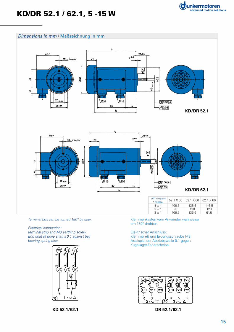
KD/DR 52.1 / 62.1, 5 -15 W
• Rugged design• Maintenance free during lifetime• Ball bearings and surface cooling by built-in blower for maximum lifetime• Three-phase, four-pole design• Reversible rotational direction• Available in different lengths• Can be combined with gearboxes and brakes• IP 44 protected when flange-mounted• Insulation material according to VDE 0530, corresponds to insulation class E• Surface protected by passivated housing• End shields made of die-cast aluminium
• Robuster Aufbau• Wartungsfrei während Lebensdauer• Kugellagerung und Oberflächenkühlung durch eingebauten Lüfter für maximale Lebensdauer• Dreiphasiger, vierpoliger Aufbau• Drehrichtung umkehrbar• Erhältlich in verschiedenen Baulängen• Kombination mit Getrieben und Bremsen möglich• Schutzart IP 44 im angeflanschten Zustand• Isolationsmaterial nach VDE 0530 entsprechend Isolierstoffklasse E• Oberflächenschutz durch passiviertes Gehäuse• Lagerschilder aus Aluminiumdruckguss
Versions of KD/DR 52.1 / 62.1 / Ausführungen KD/DR 52.1 / 62.1 Page / Seite
With gearbox / Als Getriebemotor from / ab 24With brake / Als Bremsmotor 22n Standard / Standard n On request / auf Anfrage
Data / Technische Daten KD 52.1x60-4 DR 52.1x60-4 KD 62.1x60-4 DR 62.1x60-4Rated voltage/Nennspannung
V 230 (50/60 Hz) ∆ 400/230 (50/60 Hz) Y / ∆ 230 (50/60 Hz) ∆ 400/230 (50/60 Hz) Y / ∆
Rated output power PN /Abgegebene Nennleistung PN
W 5 6 11 15
Rated speed nN /Nenndrehzahl nN
rpm 1200 1200 1300 1200
Rated torque MN /Nenndrehmoment MN
Ncm 3.7 4.8 8.1 11.9
Phase-shifting capacitor 1) /Betriebs-Kondensator 1)Capacitance CB / Kapazität CB
Voltage UC / Spannung UC
µF V˜
1.15240
--
2260
--
Rated current IN /Nennstrom IN (at 400 V at type DR)
A 0.11 0.06 0.17 0.10
Starting torque MA /Anzugsmoment MA
Ncm 3.5 7.5 6.5 21
Pull-out torque MK /Kippmoment MK
Ncm 4.2 - 11.0 -
Moment of inertia J /Massenträgheitsmoment J
gcm2 206 234 280 280
Weight m/Gewicht m (B 14 DIN 42950)
kg 1.2 1.2 1.6 1.6
15
deep/tief
KD/DR 52.1 / 62.1, 5 -15 W
Dimensions in mm / Maßzeichnung in mm
deep/tief
KD 52.1/62.1 DR 52.1/62.1
dimension / Maße
52.1 X 30 52.1 X 60 62.1 X 60
l1 ± 1 106.5 136.6 146.5l2 ± 1 90 120 128l3 ± 1 106.5 136.6 61.5
Terminal box can be turned 180° by user.
Electrical connection:terminal strip and M3 earthing screw.End float of drive shaft ≤0.1 against ballbearing spring disc.
Klemmenkasten vom Anwender wahlweiseum 180° drehbar.
Elektrischer Anschluss:Klemmbrett und Erdungsschraube M3.Axialspiel der Abtriebswelle 0.1 gegenKugellager-Federscheibe.
KD/DR 52.1
KD/DR 62.1
16
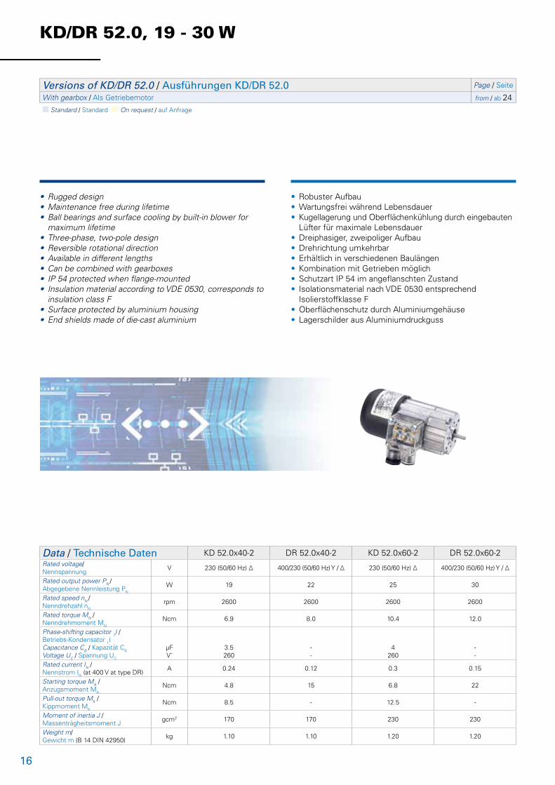
KD/DR 52.0, 19 - 30 W
• Rugged design• Maintenance free during lifetime• Ball bearings and surface cooling by built-in blower for maximum lifetime• Three-phase, two-pole design• Reversible rotational direction• Available in different lengths• Can be combined with gearboxes• IP 54 protected when flange-mounted• Insulation material according to VDE 0530, corresponds to insulation class F• Surface protected by aluminium housing• End shields made of die-cast aluminium
• Robuster Aufbau• Wartungsfrei während Lebensdauer• Kugellagerung und Oberflächenkühlung durch eingebauten Lüfter für maximale Lebensdauer• Dreiphasiger, zweipoliger Aufbau• Drehrichtung umkehrbar• Erhältlich in verschiedenen Baulängen• Kombination mit Getrieben möglich• Schutzart IP 54 im angeflanschten Zustand• Isolationsmaterial nach VDE 0530 entsprechend Isolierstoffklasse F• Oberflächenschutz durch Aluminiumgehäuse• Lagerschilder aus Aluminiumdruckguss
Versions of KD/DR 52.0 / Ausführungen KD/DR 52.0 Page / Seite
With gearbox / Als Getriebemotor from / ab 24n Standard / Standard n On request / auf Anfrage
Data / Technische Daten KD 52.0x40-2 DR 52.0x40-2 KD 52.0x60-2 DR 52.0x60-2Rated voltage/Nennspannung
V 230 (50/60 Hz) ∆ 400/230 (50/60 Hz) Y / ∆ 230 (50/60 Hz) ∆ 400/230 (50/60 Hz) Y / ∆
Rated output power PN /Abgegebene Nennleistung PN
W 19 22 25 30
Rated speed nN /Nenndrehzahl nN
rpm 2600 2600 2600 2600
Rated torque MN /Nenndrehmoment MN
Ncm 6.9 8.0 10.4 12.0
Phase-shifting capacitor 1) /Betriebs-Kondensator 1)Capacitance CB / Kapazität CB
Voltage UC / Spannung UC
µF V˜
3.5260
--
4260
--
Rated current IN /Nennstrom IN (at 400 V at type DR)
A 0.24 0.12 0.3 0.15
Starting torque MA /Anzugsmoment MA
Ncm 4.8 15 6.8 22
Pull-out torque MK /Kippmoment MK
Ncm 8.5 - 12.5 -
Moment of inertia J /Massenträgheitsmoment J
gcm2 170 170 230 230
Weight m/Gewicht m (B 14 DIN 42950)
kg 1.10 1.10 1.20 1.20

17
KD/DR 52.0, 19 - 30 W
deep/tief
Dimensions in mm / Maßzeichnung in mm
dimension / Maße
52.0 X 40 52.0 X 60
l1 ± 1 130 146l2 ± 1 108.5 124.5l3 ± 1 31.5 47.5
KD 52.0 DR 52.0
Terminal box can be turned 180° by user.
Electrical connection:terminal strip and M3 earthing screw.End float of drive shaft ≤0.1 against ballbearing spring disc.
Klemmenkasten vom Anwender wahlweiseum 180° drehbar.
Elektrischer Anschluss:Klemmbrett und Erdungsschraube M3.Axialspiel der Abtriebswelle 0.1 gegenKugellager-Federscheibe.
deep/tief
Metal Terminal Box IP 65 / Metallklemmkasten IP65
For the motor series KD/DR 52.0+62.0 we offer a metal terminal box. The electrical connections are according to the circuit diagram below shown.
Für die Baureihe KD/DR 52.0+62.0 steht ein Metall-klemmkasten alsAnbausatz zur Verfügung. Das 9-polige Klemmbrett wird, wie unten dargestellt, beschaltet.
dimension / Maße
52.0 X 40 52.0 X 60
l1 ± 1 130 146l2 ± 1 108.5 124.5l3 ± 1 31.5 47.5

18
KD/DR 62.0, 36 - 87 W
• Rugged design• Maintenance free during lifetime• Ball bearings and surface cooling by built-in blower for maximum lifetime• Three-phase, two-pole design• Reversible rotational direction• Available in different lengths• Can be combined with gearboxes and brakes• IP 54 protected when flange-mounted• Insulation material according to VDE 0530, corresponds to insulation class F• Surface protected by aluminium housing• End shields made of die-cast aluminium
• Robuster Aufbau• Wartungsfrei während Lebensdauer• Kugellagerung und Oberflächenkühlung durch eingebauten Lüfter für maximale Lebensdauer• Dreiphasiger, zweipoliger Aufbau• Drehrichtung umkehrbar• Erhältlich in verschiedenen Baulängen• Kombination mit Getrieben und Bremsen möglich• Schutzart IP 54 im angeflanschten Zustand• Isolationsmaterial nach VDE 0530 entsprechend Isolierstoffklasse F• Oberflächenschutz durch Aluminiumgehäuse• Lagerschilder aus Aluminiumdruckguss
Versions of KD/DR 62.0 / Ausführungen KD/DR 62.0 Page / Seite
With gearbox / Als Getriebemotor from / ab 24With brake / Als Bremsmotor 22n Standard / Standard n On request / auf Anfrage
Data / Technische Daten KD 62.0x40-2 DR 62.0x40-2 KD 62.0x60-2 DR 62.0x60-2 KD 62.0x80-2 DR 62.0x80-2Rated voltage/Nennspannung
V 230 (50/60 Hz) ∆ 400/230 (50/60 Hz) Y / ∆ 230 (50/60 Hz) ∆ 400/230
(50/60 Hz) Y / ∆ 230 (50/60 Hz) ∆ 400/230 (50/60 Hz) Y / ∆
Rated output power PN /Abgegebene Nennleistung PN
W 36 42 54 66 76 87
Rated speed nN /Nenndrehzahl nN
rpm 2600 2600 2600 2600 2600 2600
Rated torque MN /Nenndrehmoment MN
Ncm 13.8 15.8 22.0 24.5 28.0 31.5
Phase-shifting capacitor 1) /Betriebs-Kondensator 1)Capacitance CB / Kapazität CB
Voltage UC / Spannung UC
µF V˜
5260
--
7260
--
8250
--
Rated current IN /Nennstrom IN (at 400 V at type DR)
A 0.38 0.19 0.54 0.26 0.66 0.31
Starting torque MA /Anzugsmoment MA
Ncm 10 33 14 58 16 72
Pull-out torque MK /Kippmoment MK
Ncm 17 - 27 - 33.5 -
Moment of inertia J /Massenträgheitsmoment J
gcm2 240 240 290 290 370 370
Weight m/Gewicht m (B 14 DIN 42950)
kg 1.35 1.35 1.60 1.60 2.00 2.00

19
deep/tief
KD/DR 62.0, 36 - 87 W
dimension / Maße
52.0 X 40 52.0 X 60
l1 ± 1 130 146l2 ± 1 108.5 124.5l3 ± 1 31.5 47.5
Dimensions in mm / Maßzeichnung in mm
KD 52.0 DR 52.0
Terminal box can be turned 180° by user.
Electrical connection:terminal strip and M3 earthing screw.End float of drive shaft ≤0.1 against ballbearing spring disc.
Klemmenkasten vom Anwender wahlweiseum 180° drehbar.
Elektrischer Anschluss:Klemmbrett und Erdungsschraube M3.Axialspiel der Abtriebswelle 0.1 gegenKugellager-Federscheibe.
deep/tief
Metal Terminal Box IP 65 / Metallklemmkasten IP65
For the motor series KD/DR 52.0+62.0 we offer a metal terminal box. The electrical connections are according to the circuit diagram below shown.
Für die Baureihe KD/DR 52.0+62.0 steht ein Metall-klemmkasten alsAnbausatz zur Verfügung. Das 9-polige Klemmbrett wird, wie unten dargestellt, beschaltet.
dimension / Maße
52.0 X 40 52.0 X 60
l1 ± 1 130 146l2 ± 1 108.5 124.5l3 ± 1 31.5 47.5

20
KD/DR 62.0, 14 - 31 W
• Rugged design• Maintenance free during lifetime• Ball bearings and surface cooling by built-in blower for maximum lifetime• Three-phase, four-pole design• Reversible rotational direction• Available in different lengths• Can be combined with gearboxes and brakes• IP 54 protected when flange-mounted• Insulation material according to VDE 0530, corresponds to insulation class F• Surface protected by aluminium housing• End shields made of die-cast aluminium
• Robuster Aufbau• Wartungsfrei während Lebensdauer• Kugellagerung und Oberflächenkühlung durch eingebauten Lüfter für maximale Lebensdauer• Dreiphasiger, vierpoliger Aufbau• Drehrichtung umkehrbar• Erhältlich in verschiedenen Baulängen• Kombination mit Getrieben und Bremsen möglich• Schutzart IP 54 im angeflanschten Zustand• Isolationsmaterial nach VDE 0530 entsprechend Isolierstoffklasse F• Oberflächenschutz durch Aluminiumgehäuse• Lagerschilder aus Aluminiumdruckguss
Versions of KD/DR 62.0 / Ausführungen KD/DR 62.0 Page / Seite
With gearbox / Als Getriebemotor from / ab 24With brake / Als Bremsmotor 22n Standard / Standard n On request / auf Anfrage
Data / Technische Daten KD 62.0x40-4 DR 62.0x40-4 KD 62.0x60-4 DR 62.0x60-4 KD 62.0x80-4 DR 62.0x80-4Rated voltage/Nennspannung
V 230 (50/60 Hz) ∆
400/230 (50/60 Hz) Y / ∆
230 (50/60 Hz) ∆
400/230 (50/60 Hz) Y / ∆
230 (50/60 Hz) ∆
400/230 (50/60 Hz) Y / ∆
Rated output power PN /Abgegebene Nennleistung PN
W 14 18 20 24 25 31
Rated speed nN /Nenndrehzahl nN
rpm 1200 1100 1200 1100 1200 1100
Rated torque MN /Nenndrehmoment MN
Ncm 12.2 17.2 17.8 23.5 20.2 27.8
Phase-shifting capacitor 1) /Betriebs-Kondensator 1)Capacitance CB / Kapazität CB
Voltage UC / Spannung UC
µF V˜
3.5260
--
4260
--
5260
--
Rated current IN /Nennstrom IN (at 400 V at type DR)
A 0.25 0.13 0.30 0.15 0.37 0.19
Starting torque MA /Anzugsmoment MA
Ncm 9.8 24 12 34 16 42
Pull-out torque MK /Kippmoment MK
Ncm 18 - 20 - 23.5 -
Moment of inertia J /Massenträgheitsmoment J
gcm2 240 240 290 290 370 370
Weight m/Gewicht m (B 14 DIN 42950)
kg 1.35 1.35 1.60 1.60 2.00 2.00

21
KD/DR 62.0, 14 - 31 W
KD 52.0 DR 52.0
Terminal box can be turned 180° by user.
Electrical connection:terminal strip and M3 earthing screw.End float of drive shaft ≤0.1 against ballbearing spring disc.
Klemmenkasten vom Anwender wahlweiseum 180° drehbar.
Elektrischer Anschluss:Klemmbrett und Erdungsschraube M3.Axialspiel der Abtriebswelle 0.1 gegenKugellager-Federscheibe.
deep/tief
Dimensions in mm / Maßzeichnung in mm
deep/tief
Metal Terminal Box IP 65 / Metallklemmkasten IP65
For the motor series KD/DR 52.0+62.0 we offer a metal terminal box. The electrical connections are according to the circuit diagram below shown.
Für die Baureihe KD/DR 52.0+62.0 steht ein Metall-klemmkasten alsAnbausatz zur Verfügung. Das 9-polige Klemmbrett wird, wie unten dargestellt, beschaltet.
dimension / Maße
62.0x40 62.0x60 62.0x80
l1 ± 1 133 149 169l2 ± 1 108.5 124.5 144.5l3 ± 1 31.5 47.5 67.5
dimension / Maße
62.0x40 62.0x60 62.0x80
l1 ± 1 133 149 169l2 ± 1 108.5 124.5 144.5l3 ± 1 31.5 47.5 67.5

22
Design and application• All alternating-current motors can be supplied with armature-stop brake.• A plastic coil former is push-fitted over an E-core of dynamo sheet.• When no current is flowing in the coil, the motor is braked by two compression springs pressing the brake disc and the brake plate together.• When current flows in the coil the E-core counteracts the spring force, pulling the brake plate towards it, and the brake is released.
Aufbau und Verwendung• Alle Motoren können mit Ankerstoppbremsen geliefert werden.• Über einen E-Kern aus Dynamoblech ist ein Kunststoffkörper als Spulenträger geschoben.• Die Bremsung erfolgt im unbestromten Zustand durch Gegeneinanderpressen von Bremsscheibe und Bremsplatte durch zwei Druckfedern.• Das Anziehen der Bremsplatte durch den E-Kern im bestromten Zustand wirkt der Federkraft entgegen – die Bremse lüftet.
Data / Technische Daten ASTO-E40 ASTO-E60Operating voltage UB/Betriebsspannung UB
V / Hz 230 / 50 230 / 50
Brake torque /Bremsmoment*
Ncm 14 42
Current consumption I/Stromaufnahme I
mA 70 105
Power consumption P /Aufnahmeleistung P
W 9 14.5
Resistance R /Widerstand R
Ω 1023 297
Weigh /Gewicht
kg 0.20 0.55
Protection /Schutzart
IP 20 54
Insulation class /Isolierstoffklasse B B
* This does not take the moment of inertia of the load into account. / * Das Bremsmoment bezieht sich auf den eingelaufenen Zustand. Im Anlieferzustand sind geringere Werte möglich.
Brake Motors Bremsmotoren
Series / Baureihe KD/DR/ASTO
A. C.-/Three-phase motors with Brake / Wechselstrom-/Drehstrommotoren mit Bremse

23
Brake Motors Bremsmotoren
Motor KD/DR 52.1 ASTO E40
Motor KD/DR 62.1 ASTO E40
Motor KD/DR 62.0 ASTO E60
Series / Baureihe KD/DR/ASTO
A. C.-/Three-phase motors with Brake / Wechselstrom-/Drehstrommotoren mit Bremse
dimension / Maße
52.1 X 30 52.1 X 60
l1 ± 1 136 166l2 ± 1 90 120l3 ± 1 23.5 53.5
dimension / Maße
62.1 X 60
l1 ± 1 176l2 ± 1 128l3 ± 1 61.5
dimension / Maße
62.0 X 40 62.0 X 60 62.0 X 80
l1 ± 1 176.5 192.5 212.5l2 ± 1 152 168 188l3 ± 1 31.5 47.5 67.5

24
PLG 52
• Compact, industry compatible planetary gearbox• High efficiency• Ring gear, planetary carriers and sun wheels made of steel• Welded output shaft on request, plain bearings for planetary gears and nitrided ring gear available for high level requirements• Output shaft with dual ball bearings• All stages have straight toothing
• Kompaktes, industrietaugliches Planetengetriebe• Hoher Wirkungsgrad• Hohlrad, Planetenträger und Sonnenritzel aus Stahl• Optional geschweißte Ausgangswelle, Laufbuchsen für Planetenräder und nitriertes Hohlrad für gehobene Ansprüche• Ausgangswelle doppelt kugelgelagert• Alle Getriebestufen geradeverzahnt ausgeführt
Data / Technische DatenPLG 52 - Ring gear Steel / Hohlrad StahlReduction ratio/Untersetzungsverhältnis 4 6.25 8 15 20.25 28.12 36 50 64 91.12 126.5 162 225 288 400 512
Efficiency/Wirkungsgrad 0.9 0.81 0.73
Number of stages/Stufenzahl 1 2 3
Continuous torque/Dauerdrehmoment Ncm 120 800 2400
Weight of gearbox/Getriebegewicht kg 0.56 0.72 0.88
Axial load/radial load/Axiallast/Radiallast N 500/350 500/350 500/350
n Standard / Standard n On request / auf Anfrage

25
PLG 52
Lengths L motor gearbox combination / Länge L Antrieb (mm ± 2)
PLG 52
Stages / Stufenzahl 1 2 3
KD 52.0x40/ DR 52.0x40 180 195.5 210.5
KD 52.0x60/ DR 52.0x60 196 211.5 226.5
KD 52.1x30/ DR 52.1x30 156.5 172 187
KD 52.1x60/ DR 52.1x60 186.5 202 217
KD 62.0x40/ DR 62.0x40 183 198.5 213.5
KD 62.0x60/ DR 62.0x60 199 214.5 229.5
KD 62.0x80/ DR 62.0x80 219 234.5 249.5
KD 62.1x60/ DR 62.1x60 196.5 212 227
M5
7.5 Dept
h/Tiefe
40±0.1
0.2 A
0.05 A
0.03
Ø52
C
A
B
/ ScheibenfederWoodruff key DIN 6888 Series A
12
3
25±1
0 Ø32 -0.039 +0.00
8
Ø1
2 +0.0
03
Nom
Motor
4 x 6.5
PLG 52.0 / PLG 52 H
L

26
PLG 52 H - Low Noise
• Compact, industry compatible planetary gearbox• Quiet operation due to helical gears in 1st stage, 2nd and 3rd stage have straight toothing• High efficiency• Ring gear, planetary carriers and sun wheels made of steel, ring gear of first stage is made of zinc diecast• Welded output shaft on request, plain bearings for planetary gears and nitrided ring gear available for high level requirements• Output shaft with dual ball bearings
• Kompaktes, industrietaugliches Planetengetriebe• Für hohe Laufruhe ist erste Getriebestufe schrägverzahnt ausgeführt, 2. und 3. Getriebestufe geradeverzahnt• Hoher Wirkungsgrad• Hohlrad, Planetenträger und Sonnenritzel aus Stahl, Hohlrad der ersten Stufe aus Zinkdruckguss• Optional geschweißte Ausgangswelle, Laufbuchsen für Planetenräder und nitriertes Hohlrad für gehobene Ansprüche• Ausgangswelle doppelt kugelgelagert
Data / Technische DatenPLG 52 H - Low NoiseReduction ratio/Untersetzungsverhältnis 4.5 6.25 8 15 20.25 28.12 36 50 64 91.12 126.5 162 225 288 400 512
Efficiency/Wirkungsgrad 0.9 0.81 0.73
Number of stages/Stufenzahl 1 2 3
Continuous torque/Dauerdrehmoment Ncm 120 800 2400
Weight of gearbox/Getriebegewicht kg 0.6 0.72 0.88
Axial load/radial load/Axiallast/Radiallast N 500/350 500/350 500/350
n Standard / Standard n On request / auf Anfrage

27
PLG 52 H - Low Noise
Lengths L motor gearbox combination / Länge L Antrieb (mm ± 2)
PLG 52 H
Stages / Stufenzahl 1 2 3
KD 52.0x40/ DR 52.0x40 180 195.5 210.5
KD 52.0x60/ DR 52.0x60 196 211.5 226.5
KD 52.1x30/ DR 52.1x30 156.5 172 187
KD 52.1x60/ DR 52.1x60 186.5 202 217
KD 62.0x40/ DR 62.0x40 183 198.5 213.5
KD 62.0x60/ DR 62.0x60 199 214.5 229.5
KD 62.0x80/ DR 62.0x80 219 234.5 249.5
KD 62.1x60/ DR 62.1x60 196.5 212 227
M5
7.5 Dept
h/Tiefe
40±0.1
0.2 A
0.05 A
0.03
Ø52
C
A
B
/ ScheibenfederWoodruff key DIN 6888 Series A
12
3
25±1
0 Ø32 -0.039 +0.00
8
Ø1
2 +0.0
03
Nom
Motor
4 x 6.5
PLG 52.0 / PLG 52 H
L

28
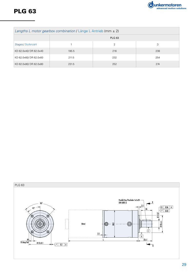
PLG 63
• Industry compatible high performance planetary gearbox• Quiet operation due to helical gears in 1st stage, 2nd and 3rd stage have straight toothing• Single stage gearboxes with brass gears, high grade material for quiet operation on request• High efficiency• Planetary carriers and sun wheels made of steel, ring gear made of nitrided steel, ring gear of first stage is made of zinc diecast• Output shaft with dual ball bearings
• Industrietaugliches, drehmomentstarkes Planetengetriebe• Für hohe Laufruhe ist erste Getriebestufe schrägverzahnt ausgeführt, 2. und 3. Getriebestufe geradeverzahnt• Einstufige Getriebe mit Messing-Planetenrädern. Planetenräder aus hochwertigem Kunststoff für besondere Laufruhe auf Anfrage• Hoher Wirkungsgrad• Planetenträger und Sonnenritzel aus Stahl, Hohlrad aus nitriertem Stahl, Hohlrad der ersten Stufe aus Zinkdruckguss• Ausgangswelle doppelt kugelgelagert
Data / Technische DatenPLG 63 - Ring gear steel / Hohlrad StahlReduction ratio/Untersetzungsverhältnis 3 4 7 10 14.5 16.8 29.4 35 60.9 101.5
Efficiency/Wirkungsgrad 0.85 0.72
Number of stages/Stufenzahl 1 2
Continuous torque/Dauerdrehmoment Ncm 500 (plastic planet gears, Kunststoff-Planetenräder) /1500 7000
Weight of gearbox/Getriebegewicht kg 1.1 2.2
Axial load/radial load/Axiallast/Radiallast N 800/800 800/800
Data / Technische DatenPLG 63 - Ring gear steel / Hohlrad StahlReduction ratio/Untersetzungsverhältnis 70.56 84 100 147 175 210 250 304.5 362.5 426.3 507.5 710.5
Efficiency/Wirkungsgrad 0.61
Number of stages/Stufenzahl 3
Continuous torque/Dauerdrehmoment Ncm 10000
Weight of gearbox/Getriebegewicht kg 3.3
Axial load/radial load/Axiallast/Radiallast N 800/800
n Standard / Standard n On request / auf Anfrage
29
PLG 63
Lengths L motor gearbox combination / Länge L Antrieb (mm ± 2)
PLG 63
Stages / Stufenzahl 1 2 3
KD 62.0x40/ DR 62.0x40 195.5 216 238
KD 62.0x60/ DR 62.0x60 211.5 232 254
KD 62.0x80/ DR 62.0x80 231.5 252 274
Data / Technische DatenPLG 63 - Ring gear steel / Hohlrad StahlReduction ratio/Untersetzungsverhältnis 3 4 7 10 14.5 16.8 29.4 35 60.9 101.5
Efficiency/Wirkungsgrad 0.85 0.72
Number of stages/Stufenzahl 1 2
Continuous torque/Dauerdrehmoment Ncm 500 (plastic planet gears, Kunststoff-Planetenräder) /1500 7000
Weight of gearbox/Getriebegewicht kg 1.1 2.2
Axial load/radial load/Axiallast/Radiallast N 800/800 800/800
Data / Technische DatenPLG 63 - Ring gear steel / Hohlrad StahlReduction ratio/Untersetzungsverhältnis 70.56 84 100 147 175 210 250 304.5 362.5 426.3 507.5 710.5
Efficiency/Wirkungsgrad 0.61
Number of stages/Stufenzahl 3
Continuous torque/Dauerdrehmoment Ncm 10000
Weight of gearbox/Getriebegewicht kg 3.3
Axial load/radial load/Axiallast/Radiallast N 800/800
n Standard / Standard n On request / auf Anfrage
Ø 52±0.1
Parallel Key/Passfeder 5x5x20DIN 6885-A
0.2 A
M510 deep/tief
90°
45°
Motor
3.5
Ø63
L 32±1
2.526
0.06 A
0.03
A
B
B
C
Ø 15
h7Ø
40-0
.011
PLG 63

30
PLG 75
• Industry compatible high performance planetary gearbox• Quiet operation due to helical gears in 1st stage, 2nd and 3rd stage have straight toothing• High efficiency• Planetary carriers and sun wheels made of steel, ring gear made of nitrided steel, ring gear of first stage is made of zinc diecast• Output shaft with dual ball bearings
• Industrietaugliches, drehmomentstarkes Planetengetriebe• Für hohe Laufruhe ist erste Getriebestufe schrägverzahnt ausgeführt, 2. und 3. Getriebestufe geradeverzahnt• Hoher Wirkungsgrad• Planetenträger und Sonnenritzel aus Stahl, Hohlrad aus nitriertem Stahl, Hohlrad der ersten Stufe aus Zinkdruckguss • Ausgangswelle doppelt kugelgelagert
Data / Technische DatenPLG 75 - Ring gear steel / Hohlrad StahlReduction ratio/Untersetzungsverhältnis 4 5.5 7 10 14.5 16.8 23.1 27.5 29.4 35 42 50 70
Efficiency/Wirkungsgrad 0.85 0.72
Number of stages/Stufenzahl 1 2
Continuous torque/Dauerdrehmoment Ncm up to / bis 2500 up to / bis 12000
Weight of gearbox/Getriebegewicht kg 1.5 2.6
Axial load/radial load/Axiallast/Radiallast N 1000/1000 1000/1000
Data / Technische DatenPLG 75 - Ring gear steel / Hohlrad StahlReduction ratio/Untersetzungsverhältnis 70.56 84 100 147 175 210 250 304.5 362.5 426.3 507.5 710.5
Efficiency/Wirkungsgrad 0.61
Number of stages/Stufenzahl 3
Continuous torque/Dauerdrehmoment Ncm up to / bis 16000
Weight of gearbox/Getriebegewicht kg 3.7
Axial load/radial load/Axiallast/Radiallast N 1000/1000
n Standard / Standard n On request / auf Anfrage

31
PLG 75
Lengths L motor gearbox combination / Länge L Antrieb (mm ± 2)
PLG 75
Stages / Stufenzahl 1 2 3
KD 62.0x40/ DR 62.0x40 213 239 266
KD 62.0x60/ DR 62.0x60 229 255 282
KD 62.0x80/ DR 62.0x80 249 275 302
Motor
Parallel Key/Passfeder 6x6x28DIN 6885
A0.2
3.5
90°
Ø 65±0.1
Ø75±
0.4
A
B
49±1
B
Ø19 h
7
5B
A0.050.03
Centring/Zentrierung M6 18 deep/tief
M6 16 deep/tief
4045°
Ø 50 -0.050+0.011
L
PLG 75

32
SG 62
• Housing made of high-tensile die-cast• Worm wheel made of brass • Standard output shaft with dual ball bearings, shaft output to the left• Shaft output to the right or double shaft output on demand
• Gehäuse aus hochfestem Druckguss• Schneckenrad aus Messing• Getriebe Ausgangswelle ist serienmäßig doppelt kugelgelagert und einseitig links ausgeführt• Optional Wellenausgang rechts oder mit beidseitigem Wellenausgang
Data / Technische DatenSG 62Reduction ratio/Untersetzungsverhältnis 8 15 23 35 46 72
Efficiency/Wirkungsgrad 0.6 0.55 0.5 0.45 0.4 0.3
Continuous torque/Dauerdrehmoment Ncm 150
Weight of gearbox/Getriebegewicht kg 0.3
Axial load/radial load/Axiallast/Radiallast N 40/40
n Standard / Standard n On request / auf Anfrage
WL1 Standard version,shaft on left
WL1 StandardausführungWelle links
WL2 Special version, shaft on right
WL2 SonderausführungWelle rechts
WL3 Special version, shafts on both sides
WL3 SonderausführungWelle beidseitig

33
SG 62
Lengths L motor gearbox combination / Länge L Antrieb (mm ± 2)
SG 62
Stages / Stufenzahl 1
KD 52.1x30/ DR 52.1x30 157.5
KD 52.1x60/ DR 52.1x60 187.5
SG 62

34
SG 80
• Housing made of high-tensile die-cast • Worm wheel made of brass• Standard output shaft with dual ball bearings, shaft output to the left• Shaft output to the right or double shaft output on demand• Hollow shaft version available on demand
• Gehäuse aus hochfestem Druckguss • Schneckenrad aus Messing • Getriebe Ausgangswelle ist serienmäßig kugelgelagert und einseitig links ausgeführt• Optional Wellenausgang rechts oder mit beidseitigem Wellenausgang• Optional als Hohlwellenversion verfügbar
WL1 Standard version,shaft on left
WL1 StandardausführungWelle links
WL2 Special version, shaft on right
WL2 SonderausführungWelle rechts
WL3 Special version, shafts on both sides
WL3 SonderausführungWelle beidseitig
Data / Technische DatenSG 80 / SG 80 HReduction ratio/Untersetzungsverhältnis 5 10 15 24 38 50 75
Efficiency/Wirkungsgrad 0.7 0.65 0.55 0.5 0.4 0.35 0.25
Continuous torque/Dauerdrehmoment Ncm 1000* 800
Weight of gearbox/Getriebegewicht kg ca 0.9
Axial load/radial load/Axiallast/Radiallast N 300/350
* 1000 Ncm only possible if fixed on 50 mm bolt-hole circle / * 1000 Ncm nur möglich, wenn an Teilkreis 50 mm angeschraubt
n Standard / Standard n On request / auf Anfrage

35
SG 80
Lengths L motor gearbox combination / Länge L Antrieb (mm ± 2)
SG 80
Stages / Stufenzahl 1
KD 52.0x40/ DR 52.0x40 201
KD 52.0x60/ DR 52.0x60 201
KD 62.0x40/ DR 62.0x40 204
KD 62.0x60/ DR 62.0x60 220
KD 62.0x80/ DR 62.0x80 240
KD 62.1x60/ DR 62.1x60 217.5
Motor12
28
30 ±1
Ø 10
g5
0.03
0.08 A
12
A
30 ±1
3.5
5641
20.5
15 3.5
M 5, 8 tief Ø 25
-0.04
50 ±0.
1
(36)
Ø 62
7135
˜15
3135
50 ±0.1
TiefeM5x4,8 36 ±0.1
Depth/Tiefe
Depth/M4,8 30 ±0.1
SG 80 / SG 80 K
L
36
SG 120
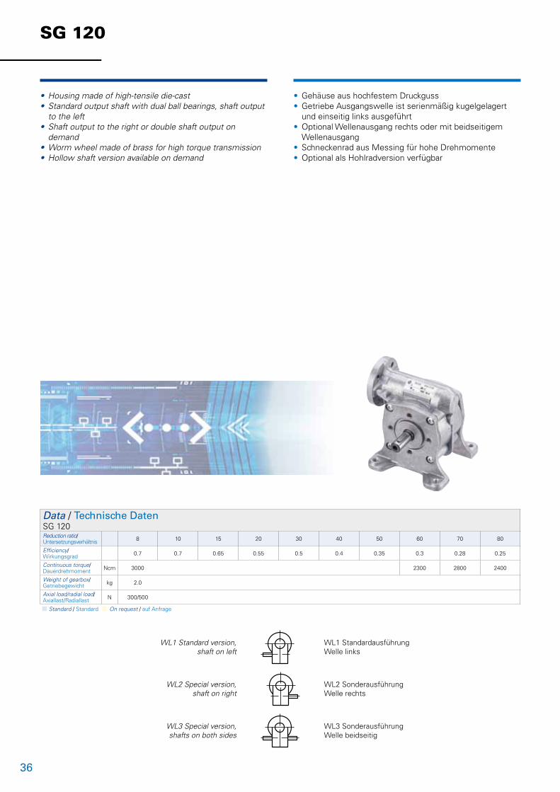
• Housing made of high-tensile die-cast• Standard output shaft with dual ball bearings, shaft output to the left• Shaft output to the right or double shaft output on demand• Worm wheel made of brass for high torque transmission• Hollow shaft version available on demand
• Gehäuse aus hochfestem Druckguss • Getriebe Ausgangswelle ist serienmäßig kugelgelagert und einseitig links ausgeführt• Optional Wellenausgang rechts oder mit beidseitigem Wellenausgang• Schneckenrad aus Messing für hohe Drehmomente• Optional als Hohlradversion verfügbar
WL1 Standard version,shaft on left
WL1 StandardausführungWelle links
WL2 Special version, shaft on right
WL2 SonderausführungWelle rechts
WL3 Special version, shafts on both sides
WL3 SonderausführungWelle beidseitig
Data / Technische DatenSG 120Reduction ratio/Untersetzungsverhältnis 8 10 15 20 30 40 50 60 70 80
Efficiency/Wirkungsgrad 0.7 0.7 0.65 0.55 0.5 0.4 0.35 0.3 0.28 0.25
Continuous torque/Dauerdrehmoment Ncm 3000 2300 2800 2400
Weight of gearbox/Getriebegewicht kg 2.0
Axial load/radial load/Axiallast/Radiallast N 300/500
n Standard / Standard n On request / auf Anfrage

37
SG 120
Lengths L motor gearbox combination / Länge L Antrieb (mm ± 2)SG 120
Stages / Stufenzahl 1
KD 62.0x40/ DR 62.0x40 243
KD 62.0x60/ DR 62.0x60 259
KD 62.0x80/ DR 62.0x80 279
Motor
SGF 120 B14 + BG 75 SI
Zentr. D M4 DIN 33235 ±0.5
WL 1
71
Ø 40
-0.1
A
Ø 14
h6 520
+0.230
0.03A0.06
R 32.5
Ø 15
2.5
8756 ±0.15
M 6 10Depth/Tiefe
65 45
4043
.5
SGF 120 B14
L
Motor
ca. 57
11090 ±0.2
71ca. 57
ca. 16.5
40±0
.1
R 32.5
65 45
4060
10Ø 6.54X M 8
Taptide M 656 ±0.12
90 ±0.2
110
SG 120
SGF 120 B5
Motor
65 45
M 680 js7
100 ±0.1
120 ±0.5
0.06 A0.03 5
Ø 14
h6
Zentr. D M4 DIN 332
20+0.2
30 R 32.5
Ø 15
3
A
35 ±0.5
42 35.5
2.5
Ø 40
8
L
L

38
Notes / Notizen

39
Notes / Notizen

Germany
Sachsen-Anhalt Nord, Berlin, Brandenburg Dunkermotoren GmbHAllmendstraße 11 · 79848 BonndorfTel. (07703) 930-0 · Fax -210/[email protected]
Niedersachsen, Hessen Nord, Westfalen OstIngenieurbüro Heinrich JürgensRoggenhof 5 · 31787 HamelnTel. (05158) 980-98 · Fax [email protected]
Hamburg/Bremen, Schleswig-Holstein, Niedersachsen Nord, Mecklenburg Vorpommern Technisches Büro Kühling/MertenRedder 1 B · 22393 HamburgTel. (040) 5234098 · Fax (040) 5282476www.kuehling-merten.de · [email protected]
Ruhrgebiet Lothar AmbornFasanenstrasse 21b · 45134 Essen-StadtwaldTel. (0201) 4435-00 · Fax [email protected]
Rheinland ATS Antriebstechnik SchloteReisertstrasse 10 · 53773 HennefTel. (02242) 90415-90 · Fax -99 [email protected]
Hessen Antriebstechnik Eberhardt GmbHLandgrabenstrasse 21 · 61118 Bad VilbelTel. (06101) 98168-0 · Fax -10www.antriebstechniken.de/[email protected]
Bayern Nord Christleven ElektrotechnikOffi ce BayreuthPreuschwitzer Str. 38 · 95445 BayreuthTel. (0921) 15 11 788-0 · Fax (0921) 15 11 788-88www.christleven.de · [email protected]
Sachsen, Thüringen, Sachsen-Anhalt Süd Christleven ElektrotechnikOffi ce ChemnitzHerrmannstr. 28a · 04741 RoßweinTel. (0921) 15 11 788-0 · Fax (0921) 15 11 788-88www.christleven.de · [email protected]
Bayern SüdChristleven ElektrotechnikOffi ce MünchenFaustnerweg 10 · 81479 MünchenTel. (089) 99 75 1476 · Fax (0921) 15 11 788-88www.christleven.de · [email protected]
Württemberg Technisches Büro SpäthEschenbrünnlestr. 16 · 71065 Sindelfi ngenTel. (07031) 794 34-60 · Fax -70www.spaeth-technik.de · [email protected]
Nordbaden, Rheinland-Pfalz, SaarlandDunkermotoren GmbH Andreas RauPostfach 11 11 13 · 76061 KarlsruheTel. (0721) 830 1021 · Fax (0721) 830 [email protected]
SüdbadenDunkermotoren GmbH Allmendstrasse 11 · 79848 BonndorfTel (07703) 930-0 · Fax (07703) [email protected]
Europe and Overseas
AustriaDunkermotorenStefan Rozic Verkaufsleiter ÖsterreichRaimundstr. 6 · 4053 Haid/ AnsfeldenTel. +43 7229 91054 · Fax +43 7229 [email protected]
Belgium / LuxembourgElmeq B.V.B.A.Industrial Zone Beveren-NoordOnledegoedstraat 79 · 8800 RoeselareTel. +32 51 25 98-11 · Fax -18www.elmeq.be · [email protected]
ChinaDunkermotoren Taicang Co., LtdNo. 9 Factory Premises · 111 North · Dongting RoadTaicang Economy Area · Taicang 215400Jiangsu ProvinceTel. +86 512 8889 8889-0 · Fax +86 512 8889 [email protected]
Area China North Dunkermotoren (Taicang) Co.,Ltd.Beijing Offi ceRoom 3109H · Fuer Plaza · No.9 Mid 3th East Ring Rd,Beijing 100020Kevin Chu (Sales Representative)Mobile +86 13811169776 · Fax+86 [email protected]
Area China SouthDunkermotoren (Taicang) Co.,Ltd. Shenzhen Representative Offi ceRoom A3 · 12 fl oor · block A · Haiwang Da XiaNanhai Da Dao · Nanshan Distric · Shenzhen City Guangdong Province 518054Barry He (Sales Manager)Tel +86 755 26431061 · Fax +86 755 26431297Mobile +86 [email protected]
Czech RepublikSchmachtl CZ s.r.o.Vestec 185 · 25242 JeseniceTel. +42 02 44 00 15 00 · Fax +42 02 44 91 07 00www.schmachtl.cz · offi [email protected]
DenmarkDJ Stork Drives ABKorskildelund · 2670 GreveTel. +45 3691 5251 · Fax. +46 8 635 60-01www.storkdrives.dk · [email protected]
FinlandWexon OYJuhanilantie 4 · 01740 VantaaTel. +358 9 290 440 · Fax +358 9 290 44100www.wexon.fi · [email protected]
FranceMDP21 Porte du Grand Lyon, Neyron01707 Miribel CédexTel. +33 4 72 01 83 00 · Fax +33 4 72 01 83 09www.mdp.fr · [email protected]
Great BritainDunkermotoren UKKingfi sher House · Suite 2 · Rownhams LaneNorth Baddesley · Southampton · Hants · SO52 9LPTel. +44 23807 33509 · Fax +44 23807 [email protected]
IsraelAvi Sasson RepresentativesP.O. Box 9270 · 61091 Tel AvivTel. +972 3 5 01 53 22 · Fax +972 3 5 03 19 [email protected]
ItalyDunkermotoren ItaliaCorso Sempione, 221 · I-20025 Legnano MI Tel. +39 0331-596165 · Fax +39 0331-455086 [email protected]
KoreaDunkermotoren Korea Ltd.Parkview 19th fl oor, Rm 1908, #6, Jeongja-DongBudang-Gu, Seongnam-Si, Gyeonggi-Do, 463-863Tel. +82 31 719 0033 · Fax +82 31 719 [email protected]
NetherlandsERIKS Aandrijftechniek bvBroeikweg 25 · 2871 RM SchoonhovenTel. +31 182 30 34 56 · Fax +31 182 38 69 20www.eriks-at.nl · [email protected]
PolandP.P.H. WOBIT Witold Ober · ul. Gruszkowa 4 PL 61-474 PoznanTel. +48 61 8350-800 · Fax -704www.wobit.com.pl · [email protected]
SlovakiaSchmachtl SK, s.r.o.Valchárska 3 · 82109 BratislavaTel. +421 2 582756-00 · Fax -01www.schmachtl.sk · offi [email protected]
SpainElmeq S.L.(Gran Via Center) · C/ Vilamarí 50, 3° A y B08015 BarcelonaTel. +34 93 422 70 33 · Fax +34 93 432 36 60www.elmeq.es · [email protected]
SwedenDJ Stork Drives ABBox 1037 · Vretenvägen 4 A, Solna SE-172 21 Sundbyberg Tel. +46 8 635 60-00 · Fax -01www.storkdrives.se · [email protected]
Switzerland DunkermotorenRolf Leitner Verkaufsleiter SchweizPostfach 307 · 8618 Oetwil am See Tel. +41 44 799 17-71 · Fax [email protected]
Turkey Femsan Harmandere Mah. Tasocak Yolu No.8 · 81520 Kurtkoy – Pendik · IstanbulTel. +90 216 482 48 44 · Fax +90 216 482 50 52www.femsan.com · [email protected]
United States of AmericaDunkermotoren USA Inc.
HeadquarterTel. +1 815 261 9100 · Fax +1 815 356 [email protected]
Area US Mid West7105 Virginia Rd, Suite 10 – 14IL 60014 Crystal LakeTel. +1 815 261 9100 · Fax +1 815 356 [email protected]
Area US Southeast1063 Silver Gull Dr.Tega Cay, SC 29708Tel. +1 803 547 8516 · Fax +1 803 547 [email protected]
Area US Northeast18 Columbine LaneNY 11754 Kings ParkTel. +1 631 724 [email protected]
Area US Westcoast2715W 180th StreetCA 90504 TorranceTel. +1 310 323 1996 · Fax +1 310 538 [email protected]
Representatives, Distributors and Offi ces / Vertretungen und Vertriebsgesellschaften
Dunkermotoren GmbHAllmendstraße 11 · D-79848 Bonndorf/Schwarzwald
www.dunkermotoren.com · [email protected] · Phone +49 (0) 7703 930-0 · Fax +49 (0) 7703 930-210/212
© 0
9/20
10
Ges
taltu
ng/S
atz
Di2
Idee
nsch
mie
de
2000
/3.
Prin
ted
in G
erm
any
/M
D