dust migration and morphology in optically thin ... 141569a, is 2{10 myr old. near-ir images of its...
TRANSCRIPT
Dust Migration and Morphology in Optically Thin CircumstellarGas Disks1
Taku Takeuchi and Pawel ArtymowiczStockholm Observatory, Stockholm University, SE-133 36 Saltsjobaden, Sweden
ABSTRACT
We analyze the dynamics of gas-dust coupling in the presence of stellar radiation pressure incircumstellar disks, which are in a transitional stage between the gas-dominated, optically thick,primordial nebulae, and the dust-dominated, optically thin Vega-type disks. Meteoroids and dustundergo radial migration, either leaving the disk due to a strong radiation pressure, or seekinga stable equilibrium orbit in corotation with gas. In our models of A-type stars surrounded bya total gas mass from a fraction to dozens of Earth masses, the outward migration speed ofdust is comparable with the gas sound speed. Equilibrium orbits are circular, with exception ofthose significantly affected by radiation pressure, which can be strongly elliptic with apocentersextending beyond the bulk of the gas disk.
The migration of dust gives rise to radial fractionation of dust and creates a variety of pos-sible observed disk morphologies, which we compute by considering the equilibrium between thedust production (at radii . 10AU) and the dust-dust collisions removing particles from theirequilibrium orbits. Sand-sized and larger grains are distributed throughout most of the disk,with concentration near the gas pressure maximum in the inner disk. Smaller grains (typicallyin the range of 10 to 200µm) concentrate in a prominent ring structure in the outer region ofthe gas disk (presumably at radius ∼100 AU), where gas density is rapidly declining with radius.The width and density, as well as density contrast of the dust ring with respect to the inner dustdisk depend on the distribution of gas and the mechanical strength of the particles, but do notdepend on the overall dust production rate.
Our results open the prospect for deducing the distribution of gas in circumstellar disks byobserving their dust. We have qualitatively compared our models with two observed transitionaldisks around HR 4796A and HD 141569A. (Gas component has been detected, but not yetmapped in detail, in the second object.) Dust migration can result in observation of a ring ora bimodal radial dust distribution, possibly very similar to the ones produced by gap-openingplanet(s) embedded in the disk, or shepherding it from inside or outside. We conclude that aconvincing planet detection via dust imaging should include specific non-axisymmetric structure(spiral waves, streamers, resonant arcs) following from the dynamical simulations of perturbeddisks.
Subject headings: accretion, accretion disks—circumstellar matter—planetary systems: formation
1. Introduction
Dust and gas disks surround stars of differentages, from pre-main sequence to post-main se-quence stars. Because their evolution is intimatelyconnected with the process of planet formation,
1submitted to Astrophys. J.
studies of dust amount, size spectrum, mineral-ogy, and spatial distribution in disks can providevaluable information about the crucial stages ofplanet formation.
The amount of dust in disks generally decreaseswith time (Zuckerman & Becklin 1993; Natta,Grinin, & Mannings 2000). As a consequence,
1
the fraction of detectable, optically thick disks(at <3 AU from the star), decreases from nearly100% at the estimated object age ∼0.3 Myr downto a few percent at the age of ∼10 Myr (Hillen-brand & Meyer 1999; Meyer & Beckwith 2000).The amount of gas decreases as well (Zuckerman,Foreville, & Kastner 1995; Liseau & Artymow-icz 1998), especially abruptly at an age of sev-eral to ∼10 Myr for solar-type stars, when cir-cumstellar disks lose most of the primordial proto-stellar/protoplanetary material through processessuch as viscous accretion and photoionization, asdiscussed by Hollenbach et al. (2000). From theoriginal value of close to 100, the gas-to-solids (ifnot necessarily gas-to-dust) mass ratio in the TTauri and Herbig Ae/Be stars decreases duringthis period (i.e., typically at age 3–10 Myr) tomuch smaller values, eventually much less thanunity, thus leaving a predominantly dusty remnantdisk.
Vega-type stars, observable owing to their largethermal infrared (IR) excess over the extrapolatedIR stellar photospheric radiation, and sometimesresolved in scattered visible/near-IR starlight, arethought to contain such gas-poor disks. The primeexample of an object of this kind is β Pic, whichis 20–100 Myr old, and has a large disk (>103 AUradius) containing gas and dust, apparently in aratio smaller than unity (Artymowicz 1997; Liseau& Artymowicz 1998). Based on dust destructiontimescale in Vega-type disks, the disks are thought(or sometimes defined) to be continuously replen-ished by the collisions and evaporation of plan-etesimals. Most convincingly in β Pic, but alsoin a few younger, spectroscopically variable Her-big Ae stars, the existence of planetesimals andplanetary objects necessary to perturb planetes-imal orbits, has been inferred from spectroscopy(Lagrange, Backman, & Artymowicz 2000; Gradyet al. 2000).
The disks around stars with ages between 3and 10 Myr are particularly interesting, becauseof the expected presence of protoplanets, grow-ing by collisional accumulation of planetesimalsand through gas accretion (Hayashi, Nakazawa,& Nakagawa 1985; Lissauer 1993). We shall callsuch disks transitional, in reference to a transitionfrom a relatively high-mass, optically thick pri-mordial nebulae to low-mass, optically thin dustdisks. (Other names, related to the central star,
are used for the objects in which such disks re-side: young main sequence stars, or old pre-mainsequence stars; cf. Lagrange et al. 2000.)
Recent imaging of two apparently transitionaldisks, HR 4796A and HD 141569A, provided in-teresting insight into the spatial distribution ofdust. The A0 V star HR 4796A with age 8 ± 2Myr (Stauffer, Hartmann, & Barrado y Navas-cues 1995) has been imaged, first in mid-IR andafterwards in near-IR (Jayawardhana 1998; Ko-erner et al. 1998; Schneider et al. 1999; Telescoet al. 2000). The second object, B9.5 Ve starHD 141569A, is 2–10 Myr old. Near-IR imagesof its dust disk were obtained by Weinberger etal. (1999), and Augereau et al. (1999a), whilethe thermal mid-IR flux was mapped by Fisher etal. (2000). The disk in the image of HR 4796Aextends out to about 100 AU, a distance 4 timessmaller than in HD 141569A, and is significantlynarrower than its counterpart (of order 20 AU, vs.200 AU). The two systems have, however, verysimilar dust covering factor, or the ratio of to-tal IR dust luminosity to the stellar luminosity,fdust = Ldust/L∗, equal to 0.7% in HR 4796A,and 1% in HD 141569A, which are a factor of 3 to4 times larger than in β Pic.
Both disks show structure, which can be mod-eled as axisymmetric, broad rings with inner holes(near side-far side asymmetry of surface brightnessby a factor of 1.5 or less, has been interpreted asbeing due to an oblique viewing angle combinedwith anisotropic scattering by dust.) The radiiof the inner holes are ∼ 60 AU for HR 4796A(Koerner et al. 1998; Schneider et al. 1999) and∼ 150 − 200 AU for HD 141569A (Augereau etal. 1999a; Weinberger et al. 1999). The imageof HD 141569A taken at 1.1µm by Weinberger etal. (1999) has been analyzed to reveal a doublering, or ring-gap-ring morphology with the shal-low gap (or dip) in the surface brightness, cen-tered on the projected distance r = 250 AU. Thetwo maxima are found at 200 and 350 AU. Note-worthy, the same system observed at 1.6µm byAugereau et al. (1999a) shows only one broadring peaking in brightness at r = 325 AU. It isnot clear to what extent the apparent differencesin the inferred surface brightness are due to the pe-culiarities of observational techniques, such as thedifferent time lag between the registration of ob-ject and comparison star (point-spread function),
2

and to what extent by intrinsic factors like, e.g.,the possible wavelength-dependent scattering effi-ciency of dust around HD 141569A. For example,if the inner peak of HD 141569A is dominated bysmall grains, then it would Rayleigh-scatter 4.5times better at 1.1µm than at 1.6µm. Recently,HD 163296, a Herbig Ae star, was announced byGrady et al. (1999) to have a disk-and-gap mor-phology similar to that of HD 141569A.
Disks around Vega-type stars, which are moreevolved than the transitional disks discussedabove, also have inner holes or clearing regions,mostly but not always completely devoid of dust(for review see Lagrange et al. 2000). Mid-IR im-ages of the β Pic disk show the central low-densityhole (Lagage & Pantin 1994; Pantin, Lagage, &Artymowicz 1997) and submillimeter images ofFomalhaut and ε Eridani show the ring-like struc-ture of dust disks (Holland et al. 1998; Greaveset al. 1998). It is expected that the gravity ofembedded large bodies, such as planets or browndwarfs, form such inner holes in the dust distribu-tions (Roques et al. 1994; Liou & Zook 1999).
The inner holes of the transitional disks aroundHR 4796A and HD 141569A may also be producedby planetary bodies embedded in the disks (orrather, in these holes). Moreover, planetary influ-ences creating the disk “gap” at 325 AU from HD141569A (and a similar distance from HD 163296)have been proposed as an explanation of thesestriking features. Weinberger et al. (1999) es-timate that a 1.3 Jupiter mass perturber wouldopen a gap with the observed extent. Grady etal. (1999) conclude that their observations lendstrong support for early formation of massive plan-ets at distances as large as r > 300 AU from thestars.
However, there are several potential difficultieswith the proposal that giant planets form rou-tinely at such large distances in disks, in only a fewMyr. Notice that the circular orbit of a planet, re-quired by the circularity of a narrow “gap”, wouldimply a local formation history of the hypotheticalplanet. Formation in the inner disk and ejectionto a large distance by, e.g., planet-planet pertur-bations would not provide a nearly circular orbitrequired. Admittedly, radial migration of planetsvia interaction with the disk may also occur butan outward migration distance is always moder-ate. Standard theory of planet formation requires
a high surface density of solids for giant planet for-mation at large radii. For example, the numericalsimulations of planetesimal accretion at 70 AU byKenyon et al. (1999) showed that the Pluto-sizedplanets (but not the required multi-Earth massplanets) may form in 10 Myr only if the mass ofthe disk is as large as 10− 20 times the minimumsolar nebula mass (Mg ∼ 0.2 − 0.4M), a massabout 10 times larger than the typical masses ofdisks around T Tauri stars (Osterloh & Beckwith1995).
The amount of gas on the outskirts of a typicalT Tauri disk, at the age of ∼1 Myr, is probablyalso insufficient for other modes of giant planet for-mation, such as the disk fragmentation, althoughsuch a possibility in principle exists. One argu-ment against it, however, is apparent in the HD141569A system, where the surface brightness pro-file does not show any deep depletion of dust (anempty gap) such as those which quickly appeararound a giant planet in hydrodynamical models(e.g., Lubow, Seibert, & Artymowicz 1999). Onthe contrary, the “gap” is merely a 14% dip in thesurface density of dust, as compared with neigh-boring disk regions. Weinberger et al. (1999) thuspropose a very recent timing for the formation oftheir proposed Jovian perturber. Troublesome asit is for any formation scenario, this special timingrequirement seems particularly incompatible withthe early disk fragmentation scenarios.
Motivated by the apparent axisymmetry ornear-axisymmetry of the observed ring and gapstructures in disks, we devote this paper to theexploratory study of an alternative mechanismfor the appearance of a variety of possible dustmorphologies including outer dust rings and ap-parent disk gaps, connected with the phenomenonof radial migration of dust in gas disks. In thecontext of transitional disks, which are opticallythin to the stellar visible and near-UV radiationand have gas component with moderate mass, weconsider two important effects: radiation pres-sure from the central star and gas drag. As wewill show, the combination of radiation and dragforces results in an outward direction of migra-tion for the observable dust and strongly affectsthe observed disk morphology, while preservingthe usual inward direction of migration of sandand pebbles. It is easy to see why transitionaldisks support the most vigorous migration. Pri-
3

mordial protoplanetary nebulae are both opticallythick and so dense (gas:dust mass ratio ∼ 102)that most dust grains “freeze” in gas, and are notable to migrate through the gas. Vega-type stars,on the other hand, are dust dominated (Lagrangeet al. 2000). They generally contain so little gas(gas:dust 1) that the motion of dust is weaklyaffected in the grain’s lifetime. In contrast, HR4796A and HD 141569A may have gas disks com-parable with or somewhat more massive than thedust disks. Zuckerman et al. (1995) have foundCO line emission from the gas inside 130 AU dis-tance from HD 141569A. A double Hα line fromthe gas disk in the immediate vicinity of the star(Dunkin, Barlow, & Ryan 1997) also demonstratesthe existence of an extended gas disk, required forsustained accretion of gas. Whether this gas isa remnant of primordial gaseous nebula or a sec-ondary gas released by solids (for instance, evap-orating planetesimals), is not known at present.In any case, transitional disks may have substan-tial amounts of gas (many Earth masses), even ifan unfavorable viewing geometry of most systemsprecludes a spectroscopic detection of the circum-stellar absorption lines. Artymowicz (2000) arguesthat gas must be present and gas drag must beoperative in the transitional disks, or else the ra-diation pressure-boosted destruction rate of solidswould be prohibitively large.
One feature of our model, which may be observ-able, is the radial fractionation of dust accordingto grain size. The most important feature is thatat the outer edge of the gas disk, dust forms aring without the help of any shepherding bodies.Therefore, the ring structure of the dust disk doesnot necessarily indicate the existence of planets orbrown dwarfs. Klahr & Lin (2000) also proposeda model for the ring formation due to the dust mi-gration. Whether or not these models can quanti-tatively reproduce all the observational data is, ofcourse, a matter of detailed modeling, taking intoaccount each system’s scale, central star’s prop-erties, indications of dust mineralogy from spec-troscopy etc. We defer such detailed modeling oftransitional disks to a later publication, but pro-vide qualitative discussions in §7. It should, how-ever, be stressed that our model is testable againstthe existing observations, and can suggest new ob-servations. Excluding dust migration as a cause ofthe observed disk structure might, in fact, be as
important as finding that it matches the obser-vations of a given object, since such an exclusionwould very strongly support the hypothesis of dy-namical sculpting by planets.
The plan of the paper is as follows. In §2,we describe the equations of the dust grain mo-tion. In §3, we derive approximate expressions ofradial velocity of grains. We show both inwardand outward migrations of grains occur due to thecombined effect of radiation pressure and gas dragforces. In §4, we show that grains segregate in thegas disk according to their sizes and that grainsof medium size (10 − 100µm in our models) con-centrate at the edge of the gas disk. In §5, theorbital evolution of grains is calculated numeri-cally. We discuss the excitation of eccentricitiesof grain orbits at the edge of the gas disk. In §6,we calculate the lifetime of grains by taking intoaccount the collisional destruction of grains. Wederive the density structure of the dust disk anddiscuss the formation of an outer dust ring. In§7, we show a sample image in near- and mid-IRfrom our simple model. Finally, §8 discusses therelevance of the migration-induced dust structuresto observed systems, and compare them with dustfeatures of other origin.
2. Equations of Motion of Dust Grains ina Gas Disk
We consider the motion of dust grains in a gasdisk. The equation of motion of a dust grain withmass m and the position vector r is
md2
dt2r = −GMm
r2r + F rad + F PR + F g , (1)
where r is the distance of the grain from the cen-tral star, r is the unit vector directed to the grain,G is the gravitational constant, M is the cen-tral star’s mass, and F rad, F PR, and F g are theradiation pressure, Poynting-Robertson drag (PRdrag), and gas drag force, respectively.
The radiation pressure force F rad is expressedusing the ratio of radiation pressure force to thegravitational force β,
F rad = βGMm
r2r . (2)
The ratio β is written as (Burns, Lamy, & Soter
4

1979)
β =3LQPR
16πGMcsρd, (3)
where L is the central star’s luminosity, c is thespeed of light, s is the grain’s radius, ρd is thematerial density of the grain, and QPR is the radi-ation pressure coefficient averaged over the stel-lar spectrum. The values of β are calculatedusing Mie theory (Artymowicz 1988) and shownin Figure 1. The grains are assumed to con-sist of silicates. We use the laboratory measure-ments of optical constants of olivine (MgFeSiO4)and magnesium-rich pyroxene (Mg0.8Fe0.2SiO3)by Dorschner et al. (1995)2. The grains are mod-eled as porous, containing 50% volume fractionof vacuum (the volume fractions of the two sili-cates being 25% each). The density of compositegrains is then ρd = 1.25 g cm−3. For the centralstars, we used parameters of HR 4796A (solid line)and HD 141569A (dashed line), and the renormal-ized spectrum of A0 V type star Vega. The massand luminosity of HR 4796A are M = 2.5M andL = 21.0L, respectively (Jura et al. 1993; Juraet al. 1998), while for HD 141569A these param-eters are M = 2.3M and L = 22.4L (van denAncker et al. 1998).
The PR drag force F PR is
F PR = −βGMm
r2
(vrc
r +v
c
). (4)
where v is the velocity vector of the grain, and vris the velocity component in the r direction (Burnset al. 1979).
If the velocities of the grain (v) and the gas (vg)differ, the grain experiences a gas drag force F g.The sizes of grains considered in this paper aremuch smaller than the mean free path of the gasmolecules. Thus, if the velocity difference ∆v =v − vg is much smaller than the mean thermalvelocity of gas, the gas drag force is given by theEpstein drag law
F g = −πρgs2vT∆v , (5)
where ρg is the gas density and vT is 4/3 timesthe mean thermal velocity. For the gas with mean
2Optical data are available from http://www.astro.uni-jena.de/Group/Subgroups/Labor/Labor/labor.html
molecular weight µg and temperature T , vT is
vT =43
(8kT
πµgmH
)1/2
, (6)
where k is Boltzmann’s constant and mH is themass of the hydrogen atom. In the case of ∆v =|∆v| vT, the gas drag force is
F g = −πρgs2∆v∆v . (7)
A standard way to connect these two regimes is(Kwok 1975)
F g = −πρgs2(v2
T + ∆v2)1/2∆v . (8)
The stopping time by the gas drag force isdefined as ts = m∆v/|F g|. It can be madenon-dimensional by writing ts = TsΩ−1
K , whereΩK = (GM/r3)1/2 is the Keplerian angular veloc-ity. The non-dimensional stopping time can thenbe expressed as
Ts =Tss√
1 + ∆v2/v2T
, (9)
where the square root factor represents the super-sonic correction. The subsonic stopping time pa-rameter equals
Tss =4ρdsvK3ρgrvT
, (10)
where vK = (GM/r)1/2 is the Keplerian veloc-ity. When Tss = 1, particles move slowly throughthe gas and couple to it in one dynamical timescale. Such particles are said to be marginallycoupled to gas via gas drag, as opposed to theTss 1 case, representing large grains, decou-pled from the gas disk. Notice that to withina factor close to unity ρgrvT/vK equals the gassurface density Σg in a disk. This allows us toexpress Tss as Tss ≈ Σ1p/Σg, the inverse ratioof Σg and a “surface density of one solid parti-cle”, Σ1p = 4ρds/3 (mass/cross-sectional area fora spherical particle). For example, a hypotheti-cal uniform surface density gas disk with radius100 AU and total mass 3 × 10⁻⁵M, or 10 Earthmasses, would have Σg = 8.5 × 10⁻³ g/cm2, thesame as the Σ1p of an s = 51µm particle with den-sity ρd = 1.25 g cm−3. All the dust grains smallerthan about 51 µm would then be well coupled to
5

gas in such a disk, while all sand grains would havestopping times longer than one orbital period.
The velocity of gas vg can be written using theKeplerian velocity vK as
vg = vK(1− η)1/2 . (11)
Quantity η is the ratio of the pressure gradientforce to the gravitational force, equal to
η = − 1rΩ2
Kρg
dPg
dr, (12)
where r is the distance from the central star, andPg is the gas pressure. If gas pressure decreaseswith radius, which normally happens everywherein the disk except at the inner disk edge, η > 0 andthe gas orbital motion is slightly sub-Keplerian,that is slower than vK.
In this paper, we consider the dust particlesnear the mid-plane of the gas disk, where we in-troduce cylindrical coordinates (r, θ), and neglectthe fact that the grains might have finite orbitalinclinations. This is equivalent to considering thevertical motions to be averaged out by vertical in-tegration over an ensemble of particles in a shortcolumn above and below the point (r, θ). This ap-proach is justified by the generally weak couplingof vertical and planar motions of a grain in a thindisk. The equations of motion of a dust grain atr = (r, θ) with velocity v = (vr , vθ) are
dvrdt
=v2θ
r− v
2K
r
[1− β
(1− 2vr
c
)]− vKvrTsr
, (13)
d
dt(rvθ) = −βv
2Kvθc
− vKTs
(vθ − vg) , (14)
where Ts given by equation (9) depends on thevelocity of the grain.
3. Radial Migration of Solids
Small solid bodies migrate in disks with a speeddepending on their size, radiative support and gasdrag. If the radiation pressure exceeds centralstar’s gravity (β > 1), then the grains (called β-meteoroids) are blown away on a dynamical timescale, unless strongly braked by friction againstgas. We do not concern ourselves with the observ-ability of rapidly escaping β-meteoroids in this pa-per. (We do take into account their collisions with
stable disk particles, however.) In this section, weconsider grains that have nearly circular orbits andspiral in (or out) because of the drag forces.
If the angular velocities of grains are larger thanthat of gas, the grains experience headwind andlose angular momentum to move inward. Inwardmigration of a grain subject to gas drag, but noradiation pressure or the PR drag, was discussedby Adachi, Hayashi, & Nakazawa (1976) and Wei-denschilling (1977). Exposure of dust grains to theradiation pressure often causes the orbital speedof grains to be slower than that of gas. In thiscase which we study below, the back-wind givesthe grains angular momentum so that grains moveoutward. Below, we study several regimes of mi-gration allowing analytical solutions of the equa-tions of motion.
3.1. Strongly Coupled Case (Ts 1)
Consider the limiting case Ts 1, in which thestopping time ts is much smaller than the dynam-ical time scale Ω−1
K . As will be clear from the re-sults, the particle moves azimuthally at nearly thegas velocity, so that vθ ≈ vg. The grain assumesa finite terminal radial velocity vr when the radialforces come into balance so that dvr/dt = 0. Theterminal velocity follows from equation (13),
v2g − v2
K
[1− β
(1− 2vr
c
)]− vKvr
Ts= 0 . (15)
The term 2vr/c is negligible. From equations (9)and (11), the above equation becomes
vK(β − η)− 1Tss
(1 +
v2r
v2T
)1/2
vr = 0 . (16)
Solving this equation, we obtain
vr = sgn(β − η)vT√
2(17)
×
1 +[2Tss(β − η)
vKvT
]21/2
− 1
1/2
.
The particle migrates inward if β < η, or outwardif β > η.
The velocity of the grain in the azimuthal direc-tion vθ is almost equal to the gas velocity vg, butthere is a slight difference between these velocity,∆vθ = vθ − vg. The angular momentum of the
6

grain is approximated by H = mrvg. The radialmotion changes the angular momentum secularlyat a rate
dH
dt=mvgvr
2
(1− r
1− η
dη
dr
). (18)
The torque due to the gas and PR drag forcesequals
dH
dt= − m
Tss
(1 +
v2r + ∆v2
θ
v2T
)1/2
vK∆vθ−mβcvKvg ,
(19)where βc = βvK/c. As seen from equation (21)below, ∆vθ vr. Thus, ∆v2
θ in the parenthesisin the above equation can be neglected. Equatingthe above two expressions for angular momentumchange and solving for ∆vθ, the azimuthal windvelocity becomes
∆vθ = −Tss
(1 +
v2r
v2T
)−1/2
(20)
×[vr
2vK
(1− r
1− η
dη
dr
)+ βc
]vg ,
where vr is given by equation (18). Notice thatthe formulae in this subsection remain valid in thesupersonic migration regime, such as might arisefrom tight coupling of dust grain to gas, but evenstronger coupling with stellar radiation field.
3.2. Weakly Coupled Case (Ts 1)
If β > 1, grains are blown away quickly bystrong radiation pressure force. In the case ofβ 1, the radial velocity of a grain was derivedby Lecavelier des Etangs, Vidal-Madjar, & Ferlet(1998). In this subsection, we consider the motionof a grain with β < 1. The grain rotates with thespeed vθ = vK(1 − β)1/2 and angular momentumH = mrvK(1−β)1/2. The velocity difference fromthe gas is ∆vθ = vK[(1 − β)1/2 − (1− η)1/2]. Thetorque by the gas drag and PR drag forces is
dH
dt= − m
Tss
(1 +
v2r + ∆v2
θ
v2T
)1/2
vK∆vθ−mβcvKvθ .
(21)Because vr ∆vθ (see eq. [22] below), v2
r in theright hand side is neglected. The torque causesradial migration with velocity
vr =2Tss
(1 +
∆v2θ
v2T
)1/2[(
1− η
1− β
)1/2
− 1
]vK−2βcvK .
(22)
If PR drag force is negligible (the second term ineq. [22] is neglected), a grain of β < η migratesinward, and a grain of β > η migrates outward.
3.3. Connecting Formulae For ArbitraryStopping Time
If the motions of grains and gas are close tothe Keplerian circular motion, we can derive ap-proximate formulae connecting the two regimes ofweak and strong coupling of grains with gas. So-lutions of this kind, clarifying the size-dependentnature of migration, were presented for the clas-sical inward migration of grains in optically thickdisks by Adachi et al. (1976) and Weidenschilling(1977).
We assume that η, ∆vθ/vK, vr/vK, and βc =βvK/c are much smaller than unity. Based onthe assumption that grains undergo a steady-statemigration in a disk without executing large radialmotions in one turn of the orbit, we replace the fulltime derivatives d/dt in the equations of motion(13) and (14) with the advective terms vr∂/∂r. Inother words, we set ∂/∂t = 0. Then, neglectingthe second order terms of η, ∆vθ/vK, vr/vK, andβc, the azimuthal equation (14) becomes
∆vθ = −Ts
(vr2
+ βcvK
). (23)
The radial equation (13) becomes
vK(β − η) + 2∆vθ − 1Tsvr = 0 . (24)
Substituting equation (23) into equation (24), weobtain
vr =β − η − 2βcTs
Ts + T−1s
vK . (25)
Note that the stopping time Ts defined by equa-tion (9) is a function of vr and ∆vθ. Thus, vrand ∆vθ cannot be expressed analytically. If thevelocity difference of a grain with respect to gasis subsonic, Ts ≈ Tss is independent of the ve-locity of the grain. In this case, vr and ∆vθ canbe calculated analytically by replacing Ts by Tss inequations (23) and (25). In the supersonic regime,vr and ∆vθ must be found numerically by an iter-ative correction method.
3.4. Steady Orbits of Grains
At some distance from the central star, thegrain may have a steady circular orbit without
7

radial migration or any torque. On such an or-bit, dvr/dt = vr = 0 and dvθ/dt = 0. From ther-component of equations of motion (13), the az-imuthal velocity of the grain is
vθ = vK(1− β)1/2 . (26)
From the θ-component of equations of motion(14),
(vθ − vg) + βcTsvθ = 0 . (27)
The radius of the steady orbit is calculated as asolution of equation (27) for a given size of a grains (or β). If PR drag force is negligible (βcTs 1),equation (27) yields, vθ = vg, and consequently
β = η . (28)
Thus, a grain has the steady circular orbit at sucha distance r from the star, where β = η(r).
3.5. Size Dependence of Dust Particle Ve-locity
In a gas disk, small grains of β > η circu-late faster than the gas and migrate outward,while large grains of β < η rotate slower thangas and migrate inward, if PR drag force is neg-ligible. Figure 2 shows the dependence of thevelocity of grains on their size. In this figure,ρg = 2.18×10⁻¹⁷ g cm−3, vT = 1.07×105 cm s−1,and η = 2.24×10⁻². These are the values the diskin model 1, described below in §4.1, has at 70 AU.The radial velocities vr are shown by circles. Thefilled circles represent that grains move outward(vr > 0), while open circles represent that grainsmove inward (vr < 0). These symbols are plot-ted by monitoring the velocities of grains in thenumerical calculations of their orbits, described in§5. The grains smaller than 174µm migrate out-ward, while larger grains migrate inward. The ve-locity differences ∆vθ in the azimuthal directionbetween grains and gas are shown by diamonds.The grains smaller than 174µm rotate faster thangas, while larger grains rotate slower. The 174µmgrains have β = η, and thus steady circular orbitswithout radial migration.
The grains with the size 0.1 . s . 10µm havesimilar values of the radial velocity. These grains’β are much larger than η and inversely propor-tional to the grain size s (see Fig. 1). The stop-ping time of these grains are much smaller than
the orbital period (Ts = 1 at s ≈ 30µm) and pro-portional to s (eq. [10]). It is seen that the radialvelocity is constant in this size range, followingfrom equation (25).
The solid lines show the approximate formulae(23) and (25). The plotted values were obtainednumerically after several iterations for the super-sonic correction. The dashed lines show the firstguesses of iteration, which are calculated using thesubsonic stopping time Tss instead of Ts. The de-viations of the approximate and exact formulaefor the 0.1 . s . 10µm grains are due to the factthat their radial velocities are comparable to thethermal speed of gas.
4. Segregation of Dust According to Size
As shown in §3, dust grains migrate inward oroutward until they feel no net torque. The radiusof the steady orbit is the function of grain’s sizes, which is obtained as the solution of equation(27). Thus, in a gas disk, grains segregate accord-ing to their sizes. In this section, we investigatethe segregation of grains in a disk with fixed gasprofile3.
4.1. Models of Gas Disks
We assume that the temperature and densitystructures of the gas disk have power law forms.The temperature structure of the disk that istransparent to the central star’s visible radiationis (Hayashi 1981)
T = 278(L
L
)1/4 ( r
1 AU
)qK , (29)
where power law index q = −1/2. The mid-planedensity has also power law, and at the outer radiusof the disk rout, the disk has an edge of characteris-tic width ∆rout. The density structure is modeledby
ρg = ρ0
( r
1 AU
)p 12
(tanh
rout − r
∆rout+ 1
). (30)
3Gas profile will change significantly in time if the total gasmass is much smaller than the dust mass, a case which wedo not consider here. Gas migration and dust migrationhave opposite directions and magnitudes following from theconservation of total angular momentum.
8

In this model, the sound and thermal velocity csand vT are, respectively,
cs =(
ΓkTµgmH
)1/2
= 1.17× 10⁵
[Γ1.4
2.34µg
(L
L
)1/4]1/2
×( r
1 AU
)q/2cm s−1 , (31)
vT =43
(8kT
πµgmH
)1/2
= 2.11× 10⁵
[2.34µg
(L
L
)1/4]1/2
×( r
1 AU
)q/2cm s−1 , (32)
where Γ is the adiabatic exponent. The ratio of thepressure gradient force to the gravitational force ηis (eq. [12])
η = −(
csrΩK
)2 1Γ
[p+ q − r sech2x
∆rout(tanhx+ 1)
],
(33)where x = (rout − r)/∆rout.
In model 1, we adopt following assumptions.The disk gas consists of molecular hydrogen andatomic helium (µg = 2.34 and Γ = 1.4). Thecentral star has the mass and luminosity of HR4796A: M = 2.5M and L = 21.0L, respec-tively. The power law indexes of the densityand temperature are p = −2.25 [which corre-sponds to the power law index of surface density,ps = p + (q + 3)/2 = −1.0] and q = −1/2, re-spectively. The outer radius of the gas disk isrout = 100 AU. The width of the edge of gasdisk is ∆rout = Cout(cs/rΩK)routrout. The crite-rion for the Rayleigh stability at the edge of thedisk requires Cout & 1. We adopt Cout = 1.05,which yields ∆rout = 12.1 AU. The mass ofthe gas disk is Mg = 10M⊕ that corresponds toρ0 = 3.12 × 10⁻¹³ g cm−3. The dust grains havematerial density of ρd = 1.25 g cm−3. We alsoconsider the other models of the gas disk: smallergas mass (Mg = 1M⊕; model 2), steeper and gen-tler density gradient (p = −2.75, ps = −1.5; model3, and p = −1.25, ps = 0; model 4), and wideredge of the disk (Cout = 2.0; model 5). The valuesof model parameters are summarized in Table 1.
4.2. Segregation of Grains
Figure 3 shows the ratio of pressure gradientforce to the gravitational force η as a function ofradius r. The solid line shows η for model 1. Forcomparison, η of the gas disk with a wider edge(model 5) is shown as the dashed line. The value ofthe gas mass does not affect η and model 2 (Mg =1M⊕) has the same profile of η as that in model 1.The profiles of η in model 3 and 4 (different densitygradient; p = −2.75 and −1.25) are similar to thatin model 1. In model 1 (solid line), η increasesgradually with radius to 80 AU, and then morerapidly at the edge of the disk around 100 AU,because of the steep decrease in the gas densityand pressure there. A wider disk edge (cf, thedashed line) causes a more gradual rise of η.
The radius of the steady orbits of grains arecalculated from equation (27) and are plotted inFigure 4 (we plot the grain size s as a functionof radius r). In our models, the PR drag force isnegligible compared to the gas drag force exceptwhen the grains are at the outside of the disk,r & 130 AU. The dotted line shows the case inwhich the PR drag force is not included in model1 and coincides with solid line for r . 130 AU.Thus, the PR drag force can be neglected and thegrains segregate to satisfy β = η. The smallergrains stay at farther from the central star. At theedge of the disk where η varies rapidly (80 . r .110 AU), grains in the size range 10 . s . 100µmfind stable orbits. Again, a wider edge in model 5(dashed line) gives rise to a milder concentrationof grains.
5. Orbital Evolution of Dust Grains
In §3, we derived the radial velocities of grainsanalytically assuming the orbits of the grains arenearly circular. In this section, we calculate theorbital evolution of the grains numerically by in-tegrating the equations of motion (13) and (14).It will be shown that the grains migrate to settledown in their own steady circular orbits, exceptat the outer edge of the gas disk, where the eccen-tricities of the grains’ orbits are pumped up anddust disk extends beyond the gas disk.
9
5.1. Evolution of Orbital Radii and Eccen-tricities of Grains
In Vega-type and transitional disks, dust grainsare produced as ejecta of collisions between muchlarger parent bodies such as planetesimals, comets,or meteorites. These parent bodies are not af-fected by radiation pressure and have Keplerianorbits. If the velocity of ejection is much smallerthan the orbital speed, the grains produced by col-lisions have the same Keplerian velocities as theirparent bodies have. Because grains experience ra-diation pressure, the velocities of the grains arelarger than that the grain on the circular orbitwould have. Thus, the grains are endowed withorbital eccentricities e ≈ β/(1 − β) (the equal-ity becoming exact, if parent orbits are circular).However, if the density of gas is high enough thatthe stopping time is much smaller than the or-bital period, the eccentricities of grains decreasequickly by the gas drag force and grains’ orbitsare circularized. In the inner part of our modeldisks (r . 20 AU), the orbits of grains with sizes . 100µm are circularized rapidly (Tss < 1).Then, the grains spiral in or out as discussed in§3.
Figure 5 shows the evolution of the distance ofgrains from the central star, r. The grains areassumed to be produced at 10 AU with eccentric-ity e = β/(1 − β). These initial values are notimportant because the grains rapidly forget theirinitial states due to the gas drag force. The or-bits of the grains are calculated by integratingthe equations of motion (13) and (14) numeri-cally by 7th-order Runge-Kutta method. The in-tegration are performed until t = 1000Pout, wherePout = 2π/ΩK(rout) = 632yr is the orbital pe-riod at rout(= 100 AU). Figure 5a shows theevolution of orbits in model 1. The orbits of thegrains are quickly circularized and the grains mi-grate outward. The grains larger than 100µm ar-rive at their steady orbits in ∼ 100Pout, and settledown in these orbits. Smaller grains migrate tofarther locations. A grain of 20µm arrives at theradius of the steady orbit that is in the outer edgeof the disk in 1Pout, then its orbital eccentricityis pumped up. The excitation of the eccentric-ity is seen in Figure 5a as the oscillation of thedistance r. Finally, the orbital eccentricity of the20µm grain decreases due to the gas drag force,and the grain stays in the circular steady orbit.
The orbital eccentricity of a grain of 8µm is alsopumped up when the grain arrives at the edge ofthe disk, and then decreases. Because the 8µmgrain spends most of its time staying outside thedisk (it is in the gas disk only when being justaround the pericenter of the orbit), however, thegas drag force is not strong enough to damp theeccentricity quickly. Thus, the 8µm grain stays ineccentric orbit for long time (more than 1000Pout).The evolution of orbits in the disk with smaller gasmass (Mg = 1M⊕; model 2) is shown in Figure5b. The main feature of the evolution is similar tothat in model 1. The settling time for grains toarrive at the steady orbits is longer than that inmodel 1; ∼ 100Pout for 100 and 300µm grains and∼ 1000Pout for 200µm grains.
5.2. Excitation of Eccentricity at theDisk’s Outer Edge
The orbital eccentricities of grains smaller than20µm are excited when these grains arrive at theouter edge of the gas disk. These grains have largeβ (0.19 for 20µm and 0.47 for 8µm grains). Un-til the grains arrive at the disk edge, the gas dragforce on such the small grains are strong enoughthat the grains are trapped by the gas and movewith the gas. The gas rotates faster than thegrains (η = 0.10 at rout), and the grains gainangular momentum from the gas and move out-ward. Because the gas density decreases rapidlyat the disk edge, the gas drag force ceases sud-denly when the grains pass through the disk edge.Therefore, the grains are launched into the Keplerorbit (modified by the radiation pressure) with ini-tial velocity of vg = (0, vK[1 − η]1/2) at the diskedge. With this initial velocity, the orbits of thegrains are eccentric with e = (β − η)/(1 − β) andpericenters at the disk edge. After launching intothe eccentric orbits, the grains experience the gasdrag force that works to circularize the grains’ or-bits only when they are around their pericenterat the disk edge. Thus, the eccentricities of thegrains decreases slowly.
In the above discussion, we assumed that thegas density in the disk is high enough for the gasdrag force to hold the grains tightly with the gas.We arrive at the same conclusion when the gasdensity is low and the gas drag force is not strongenough to hold the grains. Consider a small grainwhose β is much larger than η at the disk edge,
10

and assume that the grain has slightly eccentricorbit. The semi-major axis and eccentricity of itsorbit are a and e, respectively. Because β η,the grain rotates much slower than the gas, andexperiences back-wind throughout its orbit, evenwhen it is at the pericenter. The evolution of theeccentricity of the orbit by the perturbating dragforce is given by the Gauss’s equation (Brouwer &Clemence 1961)
de
dt=
1vK(a)
(1− e2
1− β
)1/2
(34)
×[Fr sinψ + Fψ
(cosψ + e
1 + e cosψ+ cosψ
)],
where ψ is true anomaly, and Fr and Fψ are theradial and azimuthal components of gas drag force,respectively. At the pericenter (ψ = 0) and theapocenter (ψ = π), equation (35) becomes
de
dt= ± 2
vK(a)
(1− e2
1− β
)1/2
Fψ , (35)
where plus and minus signs correspond to the peri-center and apocenter, respectively. The grain ex-periences back-wind throughout the orbit. Thus,Fψ is positive both at the pericenter and apocen-ter. From the equation (35), it is seen that the ec-centricity increases at the pericenter and decreasesat the apocenter. When the grain is in the edge ofthe disk, the gas density at the pericenter is muchhigher than that at the apocenter. Therefore, thegrain experiences stronger back-wind at the peri-center and its eccentricity increases. The increasein the eccentricity accompanies the increase in thevelocity at the pericenter and continues until thevelocity arrives at the same velocity of the gas.When the velocity of the grain at the pericenterbecomes the same as that of the gas, the eccen-tricity has grown up to be e = (β−η)/(1−β). Af-ter the eccentricity arrives at the maximum value,it starts to decrease. This is because the gasdrag force at the pericenter pushes the positionof the pericenter slightly outward. The eccentric-ity evolves to keep the velocity of the grain at thepericenter being equal to the velocity of the gasand maintains the value of e = (β−η)/(1−β). Be-cause η is an increasing function of r, the value of ηat the pericenter increases as the pericenter movesoutward, and the eccentricity decreases. The gasdensity at the pericenter and the gas drag force
decrease as the pericenter moves outward, and thespeed of the eccentricity damping becomes moreslowly.
Figure 6a illustrates the evolution of the eccen-tricity and the semi-major axis of an 8µm grain.The average of the change in the eccentricity overone orbital period P is calculated by⟨
de
dt
⟩=
1P
∫ P
0
de
dtdt . (36)
The integration is performed numerically and theeffect of the PR drag force is included. TheGauss’s equation of the variation in the semi-major axis is
da
dt=
2ΩK(a)(1 − β)1/2(1− e2)1/2
×[Fre sinψ + Fψ
a(1− e2)r
]. (37)
The average over one orbital period, 〈da/dt〉,is calculated in analogy with equation (36). Theevolutions of a and e are shown in Figure 6a asarrows. The length of the arrows are set to beconstant and does not represent the rate of thevariation. A grain inside the disk (a . 100AU)moves outward and its eccentricity decreases. Ifthe grain’s pericenter is on the edge of the gasdisk (100 . a . 200AU and 0 < e . 0.6), its ec-centricity grows. For a grain whose pericenter isoutside the disk, the eccentricity and semi-majoraxis decrease. The evolution of the orbit of a grainwhose initial a and e are 100 AU and 0.05, respec-tively, is plotted as circles on Figure 6a. The timeinterval of plotting circles is logarithmic: the firsttime interval is 0.01Pout and each time interval is1.2 times the previous one. The last circle repre-sents the orbit at t = 1000Pout. First, the grain’ssemi-major axis and eccentricity grow, then theeccentricity turns to decrease.
In Figure 6b, the evolution of orbital elementsof a 100µm grain is shown for comparison. It isseen that the eccentricity always decreases and thesemi-major axis changes toward the value of thesteady orbit. Circles show the evolutional path ofa grain with the initial semi-major axis a = 100AUand eccentricity e = 0.5. The eccentricity de-creases quickly, and the semi-major axis decreaseat first, and then increases as the grain approachesthe steady orbit.
11

5.3. Radial Distribution of Dust Grains
The radial distribution of dust grains are ob-tained by the numerical calculation described in§5.1. Figure 7 shows the positions of the peri-center and apocenter at t = 1000Pout against thegrain size. The solid line corresponds to model1. The grains smaller than 6.7µm are blown away(launched into hyperbolic orbits when they moveto outer edge of the gas disk). The grains of6.7 ≤ s ≤ 12µm have eccentric orbits (e > 0.01)with their pericenters on the outer edge of the gasdisk. The grains larger than 12µm have circularorbits. The radii of the circular orbits coincide tothe radii calculated from the condition that theorbits are steady (eq. [27]) and shown as the dot-ted line. The dashed line corresponds to model 2(smaller gas mass; Mg = 1M⊕). Because the gasdrag force is smaller than that in model 1, the ec-centricities of small grains remain larger. The sizeof the smallest grain having circular orbit is 13µm,slightly larger than that in model 1.
In summary, the migration of dust grains pro-duced at the inner part of the gas disk proceedsas follows. First, the grains migrate outward. Thelarge grains of s > 12µm find the steady circu-lar orbits in the gas disk and settle down. Whenthe small grains (s < 12µm) arrive at the edge ofthe gas disk, their eccentricities are excited. Thegrains of 6.7 ≤ s ≤ 12µm have eccentric orbits,and make dust disk extended outside the gas disk.The grains small enough for their eccentricities tobe pumped up to e > 1 are blown away. The grainsof 10 . s . 100µm are concentrated at the edgeof the gas disk. It is expected that these grainsmake a dust ring at the edge of the gas disk. Inthe next section, we estimate the number densityof grains in the ring.
6. Lifetime and Density of Dust Grains
The grains larger than about 10µm have steadycircular orbits in the gas disk and segregate ac-cording to their sizes. The size of grains in thesteady orbit is function of distance from the starr, written as
ss = ss(r) . (38)
The grains of size ss in the steady orbit do notcollide each other, because their orbits are circu-lar. However, smaller grains (s < ss) whose steadyorbits are farther from the star flow outward and
cross the orbit of grains of size ss. These smallergrains collide and destroy the grains in the steadyorbit. In this section, we calculate the lifetime ofgrains in the steady circular orbit in the gas disk,then estimate their number density. The smallgrains (s . 10µm) extended outside the gas diskhave eccentric orbits and collide each other. Thecalculation of the lifetime of these small grains re-mains as future work.
The grains are originally produced by collisionsof parent bodies such as planetesimals or comets.In this section, we assume that these parent bod-ies are distributed in the innermost part of the gasdisk (say, ∼ 10AU). The grains produced by colli-sions migrate outward to settle down in the steadyorbits. When the grain on the steady orbit is bro-ken up by collisions, the fragments flow outwardand settle down in the new steady orbits. Thus,grains gradually migrate outward every collisionaldestructions. The steady orbit of grains of size10 . ss . 100µm are concentrated at the edge ofthe gas disk (Fig. 4). Thus, it is expected thatthe grains of 10 . ss . 100µm gather in the edgeof the gas disk and make a dust ring. The grainsare finally blown away when collisional destructionreduces their sizes so small that they cannot havesteady orbit in the gas disk.
6.1. Collisional Destruction of Grains
There are two phases of collisional destruction.A grain is broken up by a collision with largeimpact kinetic energy (catastrophic disruption),while part of a grain is ejected by a collision withsmall energy (cratering). Consider the destructionof a grain of mass m = 4πρds
3/3 by the collisionwith a grain of mass m′. The mass ∆m lost fromthe target grainm by cratering with the collisionalvelocity u is (Holsapple 1993)
∆mm
= Km′
m
( u
cm s−1
)3µ
, (39)
where K is a coefficient representing efficiency ofcratering and the value of the exponent µ is un-certain now. We assume that the mass loss ∆mis proportional to the impact energy and adoptµ = 2/3. In equation (39), ∆m/m becomes largerthan 1 for large u, that corresponds to catastrophicdisruption. Of course, ∆m/m cannot be larger
12

than 1 and should be
∆mm
= maxKm′
m
( u
cm s−1
)2
, 1. (40)
The value of K is calculated from the minimumenergy for the catastrophic disruption. Let Q∗ bethe threshold of the specific energy per unit targetmass for the catastrophic disruption. The thresh-old energy Q∗ depends on the impact velocity uand target size s, and written as (Housen & Hol-sapple 1999)
Q∗ = Q∗0
( u
km s−1
)2−3µ ( s
10 cm
)δ= Q∗
0
( s
10 cm
)δ,
(41)where we used µ = 2/3. The values of Q∗
0 areobtained by the experiments: Q∗
0 = 107 erg g−1
for rocks (Housen & Holsapple 1999) and Q∗0 =
4 × 10⁵ erg g−1 for ice (Fig. 9 in Arakawa 1999).The value of the exponent δ is uncertain. Housen& Holsapple (1990) proposed that δ = −0.24 andHousen & Holsapple (1999) recommended thatδ = −0.67. We are interested in the lifetime anddensity of grains constituting the dust ring at theedge of the gas disk. The sizes of these grains are10 . s . 100µm. Thus, we estimate Q∗ for thegrain of size s = 50µm as
Q∗ =
6.2× 10⁷ − 1.6× 10⁹ erg g−1 for rocks2.5× 106 − 6.5× 10⁷ erg g−1 for ice
,
(42)where smaller values correspond to δ = −0.24 andlarger values correspond to δ = −0.67. The defi-nition of the catastrophic disruption is ∆m/m ≥1/2, which yields
K =1
4Q∗ =
1.5× 10⁻¹⁰ − 4.0× 10⁻⁹ for rocks3.8× 10−9 − 1.0× 10⁻⁷ for ice
.
(43)
6.2. Lifetime of Grains
In this subsection, we derive the equation forthe life time of a grain of size ss on the steady or-bit. A grain ss collide with smaller grains crossingits orbit. The probability of collision with grainsin the size range [s′, s′ + ds′] in 1 sec is
pcol = σun′ds′ , (44)
where σ = π(ss + s′)2 is the collisional cross sec-tion, n′ds′ is the number density of grains in the
size range [s′, s′ + ds′], and u = |v′ − v| is therelative velocity of the grains. The velocity of thegrain ss is the same as the velocity of the gas,i.e., v = (0, vg). The velocity v′ = (v′r, v
′θ) of
the grain s′ is obtained by the orbital calculationsof grains described in §5.1. For small grains inthe inner part of the disk where the gas densityis high, the non-dimensional stopping time Ts ismuch smaller than unity. We use the analyticalformulae (18) and (21) to calculate the velocitiesof small grains if Ts 1, because numerical cal-culations of orbits consume much time. The den-sity n′ds′ is calculated from the production rateof dust grains. Let the number of grains that arein the size range [s′, s′ + ds′] and cross the circleof the radius r (the orbit of the grain ss) in 1 secbe Npro(r, s′)ds′. The number density Npro(r, s′)is assumed to have power law form in s′. We alsoassume that the grains are originally produced in-nermost part of the gas disk and flow outward.Only the grains smaller than ss cross the orbit ofthe grain ss. The grains larger than ss stay intheir steady orbits which are closer to the star,but when they are broken to pieces smaller thanss, these pieces flow outward and cross the orbitof the grain ss. Thus, the grains crossing the orbitof the grain ss are constituted of smaller grains,and Npro(r, s′)ds′ are written as
Npro(r, s′)ds′ =
N0(r)
(s′cm
)αds′ for s ≤ ss
0 for s > ss.
(45)The mass of grains crossing the orbit of the grainss in 1 sec is
Mpro =∫ ss
smin
4π3s′3ρdN0
(s′
cm
)αds′ , (46)
where smin is the minimum size of grains. In thesteady state, Mpro is independent on r and repre-sents the mass production rate of grains in the gasdisk. From equation (46),
N0(r) =3Mpro
4πρd
[∫ ss
smin
s′3(s′
cm
)α
ds′]−1
. (47)
Note that N0 is the function of r because ss is thefunction of r. The other expression of number fluxis Npro(r, s′)ds′ = 2πrhdv
′rn
′ds′, where hd is thethickness of the dust disk. Solving this equation
13

and equation (45) gives
n′ds′ =
N0
2πrhdv′r
(s′cm
)αds′ for s ≤ ss
0 for s > ss. (48)
The mass loss rate from the grain ss with mass mis
1m
dm
dt=
∫ ss
smin
∆mm
σun′ds′
=N0
2
(hd
r
)−1
(49)
×∫ ss
smin
∆mm
u
v′r
(ss + s′
r
)2 (s′
cm
)αds′ .
The life time of the grain ss is
tlife = m
(dm
dt
)−1
= 2N−10
hd
r(50)
×[∫ ss
smin
∆mm
u
v′r
(ss + s′
r
)2 (s′
cm
)α
ds′]−1
.
6.3. Spatial Density of Grains
Consider an annular part of the disk between rand r + dr. The annulus is made of the grains ofthe size [ss, ss + (dss/dr)dr]. The total number ofthe grains in the annulus is
Nddss = 2πrhdnsdr , (51)
where ns is the number density of the grains in thesteady orbits4. The number of grains destroyed bycollisions in 1 sec is
Ndesdss =Nddsstlife
=2πrhdnsdr
tlife. (52)
The supply of the grains to the annulus isNpro(r, ss)dss = N0(ss/cm)αdss. In the steadystate, the rate of destruction and supply balanceeach other. From Ndesdss = Npro(r, ss)dss, weobtain
ns =1πr2
( sscm
)α dssdr
(53)
×[∫ ss
smin
∆mm
u
v′r
(ss + s′
r
)2 (s′
cm
)αds′
]−1
.
4Note that the unit of ns is cm−3, while that of n′ is cm−4.
We define the optical depth of the dust disk inthe vertical direction using the geometrical crosssection as
τ = πs2shdns
=sshd
r2
( sscm
)α+1 dssdr
(54)
×[∫ ss
smin
∆mm
u
v′r
(ss + s′
r
)2 (s′
cm
)αds′
cm
]−1
.
Note that the density and optical depth of thegrains are independent on N0 or the productionrate of grains Mpro.
6.4. Results of Numerical Calculations
In this subsection, we calculate the life time ofgrains and density (optical depth) of the dust diskin model 1. We assume that the grains are madeof rocky material and adopt K = 1 × 10⁻⁹. Themass production rate of grains are uncertain. Themodels of dust disks (however, without gas disks)suggested that the rate of mass loss from the diskis of order 10−6M⊕yr−1 for β Pic (Artymowicz& Clampin 1997), and HR 4796A (Augereau etal. 1999b). In the steady state, the mass lossrate balances with the mass production rate. Weadopt mass production rate Mpro = 10−6M⊕yr−1.The density of grains or the optical depth of thedisk do not depend on the mass production rate,while the life time of grains is inversely propor-tional to it. The thickness of the dust disk is as-sumed to be hd = 0.1r and the minimum size ofgrains smin = 0.01µm is adopted. The power lawindex of Npro in the equation (45) is assumed tobe α = −3.5, a typical value usually assumed forcollisional cascade.
The solid line in Figure 8a shows the life timeof grains in model 1 (gas mass Mg = 10M⊕). Thegrains larger than 100µm are in the inner partof the gas disk. Their life time is order of 1000times the orbital period Pout at rout(= 100AU)and decreases with the size because larger grainsinhabit inner part of the disk where the density ofcolliding grains is higher (eq. [48]). The grains lessthan 100µm are in the edge of the gas disk. At theedge of the disk, the collisional velocity of grainsbecomes large because the gas density is not highenough for the gas drag force to hold the grainsin the same velocity. Thus, the life time of thesesmall grains is much shorter than that of larger
14
grains (s & 100µm) in the gas disk. In model1, the life time of grains is much larger than themigration time to the steady orbits (the dashedline in Fig. 8a). Thus, the grains spend most oftheir time in their steady orbit and the dust diskis mainly composed of the grains in the steadyorbit. The contribution of grains flowing towardthe steady orbit to the density of the dust disk orthe optical depth can be neglected.
The solid line in Figure 9a shows the opticaldepth of the dust disk in model 1. The dominantprofile of the optical depth is the peak at the edgeof the gas disk (∼ 90AU). This peak is made ofthe grains of 10 . ss . 100µm. Because thesegrains gather in the edge of the gas disk (see Fig.4), the density of grains becomes high and a dustring forms there. The life time of grains outsidethe gas disk (r & 100AU and s . 10µm) is muchshorter than that of grains in the gas disk. Thus,the optical depth declines steeply outside the gasdisk. The large grains (ss . 300µm) condense atthe innermost part of the gas disk. The density ofgas is high at the inner part of the disk, and stronggas drag force suppresses the collisional disruptionof grains. Thus, the optical depth at small radiusbecomes large and an inner dust disk forms at r .40AU.
6.5. Models of Dust Distribution
The structure of dust disks strongly depends onthe properties of gas disks. In this subsection, weshow how the structure of the dust disk varies withthe variation of the gas disk.
6.5.1. Small Gas Mass
The solid line in Figure 8b shows the life timeof the grains in the gas disk with smaller mass(model 2; Mg = 1M⊕). The life time of thegrains is much shorter than in model 1, becausethe weaker gas drag force results in high collisionalvelocity of grains. In model 2, the life time is com-parable or smaller than the time for the grainsto migrate to their steady orbits (the dashed linein Fig. 8b). This means that the dust disk iscomposed of both the grains in the steady orbitsand the grains flowing outward to the steady or-bits. Some grains flowing outward are destroyedbefore arriving at the steady orbit. In this case,the calculation of the density of grains described
in §6.3 is not appropriate. The ring structure atthe edge of the gas disk would be less prominent,because some of grains making the ring would bedestroyed before arriving at their steady orbit. Toobtain the structure of the dust disk, the calcula-tion taking into account the destruction of grainson the way to the steady orbit must be needed. Ifproduction rate of grains is 10 times smaller andMpro = 10−7M⊕yr−1, the life time of grains is 10times longer, and our calculation of density wouldbe appropriate. The optical depth in the modelof Mg = 1M⊕ is shown as the dashed line in Fig-ure 9a, assuming that the life time of grains aremuch larger than the migration time. The profileof the optical depth is similar to that in the modelof Mg = 10M⊕, while its magnitude is about 10times smaller. At the peak of the optical depthin the dust ring (r ≈ 90AU), τ = 1.1 × 10⁻¹ forMg = 10M⊕ and τ = 1.2× 10⁻² for Mg = 1M⊕.
6.5.2. Different Gas Profiles
In Figure 9b, we show the optical depth ofthe dust disks for various density gradients ofgas disks. The dashed line shows the disk withsteeper density gradient (the power law index ofthe gas density p = −2.75 corresponding to thatof the surface density ps = −1.5; model 3). Themass of the gas disk is the same as in model 1(Mg = 10M⊕). Because of the steeper density gra-dient, the gas density in the inner part of the diskis higher than that in model 1, while the gas den-sity at the edge of the disk is lower. The lower gasdensity at the edge of the disk causes the shorterlife time of grains and the smaller optical depth ofthe dust ring. The grains in the inner part of thedisk are strongly held by dense gas. The collisionalvelocity of these grains are small and collisional de-struction of grains is not effective. The grains inthe inner part of the disk survive longer than thegrains in model 1, and the optical depth increaseswith decreasing radius r. The inner optically thickdisk may obscure the star from the outer part ofthe disk. In this case, the grains in the outer partof the disk do not experience the radiation pres-sure force and do not have steady orbits, so thatthe dust ring would disappear.
The dotted line in Figure 9b shows the disk withthe constant surface density (p = −1.25 and ps =0; model 4). The gas density in the inner partof the disk is much lower than that in the model
15

1, while the gas density at the edge of the diskis higher. The optical depth of the dust ring islarger than in the model 1 because of the highergas density at the edge of the disk. In the gasdisk with the constant surface density, even thegrains in the innermost part of the disk are notstrongly held by gas and are destroyed in shorttime by collisions with high velocity. The numberdensity of these grains is not as large as that inmodel 1 or 3. The inner disk is optically thin.In model 4, because the optical depth decreaseswith decreasing radius r, the inner disk does notobscure the star.
In the previous models, we assumed that thegas disks have sharp outer edges (marginallyRayleigh stable at the edge where Cout = 1.05).The sharpness of the edge is not known well. Re-cent images of the dust disk of GG Tau show avery sharp edge (∆rout/rout ∼ 0.04; Guilloteau,Dutrey, & Simon 1999). However, the edge of gasdisk may be smooth. The optical depth of the dustdisk in the gas disk with smooth edge (Cout = 2.0;model 5) is shown in Figure 9c. The concentra-tion of grains at the disk edge is moderate, andthe ring feature is weak.
6.5.3. Grains of Smaller Collisional Strength
The value of the efficiency of collisional destruc-tion K is uncertain (eq. [43]). If the grains arestronger (weaker), their life time is longer (shorter)and their density is higher (lower). As an exam-ple, we show the optical depth of the dust diskwith K = 2× 10⁻⁸, which is 20 times larger thanK in model 1 and corresponds to the efficiency ofcollisional destruction of icy grains (model 6), inFigure 9d. The life time of the grains is about20 times shorter than that in model 1, and theoptical depth is also 20 times smaller. The icygrains are destroyed more easily than the rockygrains and are blown away by the radiation pres-sure more quickly. Therefore, the dust disk aremainly composed of rocky grains with little icymantle. This is consistent with the properties ofthe grains derived through the spectral fitting ofthermal emission from the HR 4796A dust ring byAugereau et al. (1999b).
7. Morphology of the Ringed Systems
We consider first the global quantities (massand luminosity) of the dust, as well as gas, in themodels, and compare them with some observedquantities. Next, we discuss the morphology ofthe model disks in the thermal and scattered lightimages.
7.1. Mass and Luminosity of Model DustRings
The mass of the dust disk Md is given by
Md =83π2ρd
∫ rout
rin
rhds3snsdr . (55)
We set rin = 50AU and rout = 150AU to calculatethe mass of the ring part of the disk. The mass ofthe dust ring in model 1 (gas massMg = 10M⊕) is9.0×10−1M⊕ and the dust mass in model 2 (Mg =1M⊕) is 1.0 × 10⁻¹M⊕. The gas to dust ratio isabout 10. Thus, the gas-dust coupling affects themotion of the gas only slightly, at best. (If thedust grains settle down in the mid-plane of thedisk, the dust density may exceed the gas density.Even in this case, the dust grains do not affect thegas motion strongly, because of the corotation ofgas and dust in steady orbits.)
The above estimate of the mass assumes thatthe dust ring is composed of grains smaller thans ∼ 200µm. Augereau et al. (1999b) suggestedthe presence of meter-sized bodies based on thespectral energy distribution of the HR 4796A dustdisk. The gas drag and radiation pressure forcehave little effect on such large bodies, so unlikefor the dust component, the distribution of thesebodies is not strongly tied to the distribution ofgas. The presence of large meteorites and plan-etesimals (which do not fall under the categoryof dust) necessarily increases the total mass of thedisk of solid matter above our estimate of the dustdisk mass. Additional calculations are needed tomodel the long-term evolution of the large bodiesin disks.
The total luminosity of thermal emission andscattered light from the dust ring is
Ld =π
2L
∫ rout
rin
s2shdns
rdr =
12L
∫ rout
rin
τ
rdr . (56)
The above equation assumes the extinction crosssection to be geometrical. The luminosity of the
16

dust ring in model 1 is 1.7 × 10⁻²L and that inmodel 2 is 2.0× 10⁻³L.
The shape of the dust ring depends on thesharpness of the edge of the gas disk (Fig. 9c). Ifthe edge is more gradual, the ring is wider and itspeak density is lower. However, the mass and lu-minosity of the ring do not strongly depend on thesharpness of the disk edge. In model 5, where thewidth of the edge is about 2 times wider than thatin model 1, the mass and luminosity of the ring areMd = 7.2 × 10⁻¹M⊕ and Ld = 1.4 × 10⁻²L, re-spectively, which are only about 20% smaller thanthose in model 1.
We can compare the above numbers with themasses of gas and dust in transitional disks. HR4796A dust ring has been observed by thermalemission (Jayawardhana 1988; Koerner et al.1998; Telesco et al. 2000) and by scattered light(Schneider et al. 1999). The emission from thedust ring has a peak around 70 AU (Schneideret al. 1999; Telesco et al. 2000). The luminosi-ties of thermal emission and scattered light areLth ' 5×10⁻³L (Jura 1991) and Lsc ' 2×10⁻³L(Schneider et al. 1999), respectively. The total lu-minosity of the ring is Ld ' 7× 10⁻³L. A similardust distribution with a peak at 72 AU and lumi-nosity Ld ' 8 × 10⁻³L is found in our model 7,where the gas disk has a smooth outer edge at 80AU and mass Mg = 4M⊕. The gas mass in model7, Mg = 4M⊕, is consistent with the observationalupper limit Mg < 7M⊕ (Zuckerman et al. 1995;Greaves et al. 2000).
The luminosities of the thermal emission andscattered light of HD 141569A are Lth ' 8×10⁻³L(Sylvester et al. 1996) and Lsc ' (2 − 4)× 10−3L(Augereau et al. 1999a; Weinberger et al. 1999),respectively. The total luminosity of the dust isLd ' 1 × 10⁻²L. The model which reproducesthe dust ring with a peak density at 325 AU andluminosity Ld ' 1 × 10⁻²L has the gas disk withan edge at 370 AU and mass Mg = 50M⊕ (model8). The inferred gas mass is consistent with themassMg ' 20−460M⊕ derived by the observation(Zuckerman et al. 1995).
Although the gas masses derived by our modelsare consistent with the observations, we must notethat any exact match could be accidental. Ourmodels have large uncertainties. In particular, theefficiency of the collisional destruction K has anorder of magnitude of uncertainty (eq. [43]). If K
of the actual grains were larger/smaller than thevalue we adopted (K = 1.0×10⁻⁹), then the grainswould be more/less easily destroyed and the massand luminosity of dust in a given gas disk wouldbe lower/higher.
7.2. Model Images of Scattered and Ther-mal Radiation
In Figure 10, we present the theoretical im-age of model 4 (constant gas surface density), in-clined to the line of sight by 60 from pole-on,in the near-IR scattered light (gray-scale bright-ness map at 1.1 µm wavelength), and the mid-IR thermal radiation (over-plotted contours of the18.2 µm flux). Our modeling is somewhat sim-plistic, in that the scattering function is assumedto be isotropic (which does not alter the generalmorphology, just removes any up-down asymme-try of the theoretical image). However, the tem-perature profile as a function of radius needs to becomputed as accurately as possible for a reliableprediction of thermal IR flux distribution, so wecompute it within Mie theory, from the assumedproperties of grains (specified earlier in §2).
The dust morphology in the model is qualita-tively similar to those inferred from observations ofthe transitional system HD 141569A. The 18.2µmflux is centrally concentrated (like that imaged byFisher et al. 2000), while the scattered light showstwo separate components: the inner disk and theouter ring, with the brightest parts being the twoprojection-enhanced ansae. If these two compo-nents are largely overlapping, they may create theimpression of a shallow gap, resembling qualita-tively the image at λ ≈ 1.1µm by Weinberger etal. (1999). [However, see Augereau et al. (1999a)for the dust distribution from their observationsat λ ≈ 1.6µm.] The model disk in Figure 10 hasa constant gas surface density with a downturnbeyond 100 AU. Model disks with surface densitydecreasing with radius (model 1 etc.) show muchmore prominent inner disks both in scattered lightand in thermal emission. Comparison with the ob-servations suggests that gas is not concentrated inthe inner part of the disk. The flat profile of gassurface density might arise after the viscous evo-lution.
In order to achieve a quantitative agreement ofour models with the observations of HD 141569A,we would need to: (i) consider non-isotropic scat-
17

tering function, (ii) allow for a more gradual outergas truncation, and (iii) convolve the theoreticalimages with the appropriate point-spread func-tions. As already mentioned, we defer the compre-hensive modeling of individual objects to a subse-quent paper.
Another system which might be qualitativelydescribed by our dust migration models, HR4796A, shows an enhanced-brightness ansae ofthe dust ring in scattered light (Schneider et al.1999), similar to our model in Figure 10. The18.2µm images also indicate a ring-like morphol-ogy (Jayawardhana et al. 1998; Koerner et al.1998; Telesco et al. 2000). In other words, thedust ring with characteristic radius of 70 AU, pro-ducing the scattered light, also produces most ofthe 18.2µm thermal radiation.
Our thermal mid-IR map shows a more cen-trally concentrated morphology, therefore ourmodeling procedure needs to be argued in order tofit the observations. Two possibilities exist. First,our model image represents the emission fromdust in steady circular orbits, and omit the possi-ble contribution by other particles, those flowingout on spiral orbits due to β > 1, and the onespumped up to high eccentricity at the edge of thedisk (see §5.2). The combined area of such dustgrains is small, but they could in principle be seenbecause of the small physical sizes, and the associ-ated higher temperatures (see Fig. 4 in Augereauet al. 1999b and Fig. 5 in Wyatt et al. 1999).We note that the thermal emission in mid-IR (thePlanck function in Wien regime) and thus thevisibility of grains in the outer ring is often verysensitive to the dust grain temperature; it is notuncommon to find that the predicted 18.2µm fluxfrom the ring becomes 6 times under just ∼20%increase in dust temperature (from 70K to 84K),which could make the model ring visible. Anotherway to assure a quantitative fit to HR 4796A datais a modification of the modeled gas profile, whichdepletes the gas inside the ring radius. Our modelwould then produce a more sharply defined ringand less dust inside the ring, because, at the re-gion where gas is depleted, collisional disruption ofdust grains is violent. This depletion of gas (anddust) might in this case be due to one or moreplanets or a low-mass companion inside about ahalf of the ring radius (∼ 40AU).
8. Discussion and Conclusions
8.1. Dynamics of Dust Migration
We have studied in the present paper the com-bined action of gas drag and radiation pressureon dust grains in optically thin circumstellar gasdisks. Our results on dust migration are as follows.
1. Grains can migrate inward or outward, de-pending on whether its azimuthal motion is fasteror slower than the rotation velocity of gas. Evengrains smaller than the blow-out radius (β > 1)have spiral trajectories in gas disks.
2. We have provided analytical formulae for theradial migration speed in §3, which agree with thedetailed numerical integrations. The radial migra-tion speed depends on gas density, but could belarge. For grain sizes s . 100µm in disks aroundA-type stars of radius comparable with 100 AUand masses of order 1−10 Earth masses it reachesa significant fraction of gas sound speed.
3. At some radius in the gas disk, a particle mayreach a stable equilibrium orbit where it corotateswith the gas. Equilibrium is always found outsidethe radius where the gas pressure is maximum.
4. The radius of the steady orbit depends onthe grain size. That dependence is given by therotation curve of the gas disk, depending on theradial gas distribution. Smaller grains normallyfind a steady orbit farther from the central star.This results in the fractionation of grains accord-ing to their sizes.
5. The eccentricity of a grain is stronglydamped through out most of the disk, but isexcited and maintained at a value up to e =(β − η)/(1− β) at the edge of the gas disk, wherethe gas density falls rapidly (e.g., as a steep powerlaw or exponentially). The rule number 3 aboveapplies then, not to the whole orbit, but to thevicinity of the pericenter of the orbit.
6. We have studied gas disk models which havedensity varying as a power law, truncated withinan adjustable scale length, always preserving theRayleigh stability of the disk, and a total massfrom a fraction to dozens of Earth masses. Theoutcome of grain migration depends on the radia-tion pressure coefficient β and the grain size5. The
5The primary dependence is on β. The approximate rangesof grain radii are cited below for β(s) based on our physical
18

fine dust fraction (β & 0.5; s . 5µm) is removedby strong radiation pressure. Dust grains with0.1 . β . 0.5, or alternatively 5 . s . 20µm,form an extended, outer dust disk component, re-siding most of the time beyond the bulk of thegas disk on eccentric orbits. Grains of intermedi-ate size (0.01 . β . 0.1 or 20µm . s . 200µm)concentrate near the outer edge of the gas disk,forming a prominent dust ring of width similar tothe scale length of gas density cutoff. Sand grainsand meteoroids (β . 0.01 or s & 200µm) stay inthe inner part of the gas disk.
8.2. Dust Morphologies and Their Ob-servability
We considered collisions between each grain sizefraction. The steady orbits can be called parkingorbits at best. After one collisional time (whichis typically much longer than the migration time,but much shorter than the age of the system) thegrains are fragmented or eroded, jumping into asmaller grain fraction and moving to a new park-ing orbit or out into the interstellar space. Thegrains are continuously replenished, in our modelsfrom the inner part of the disk at radii of order10 AU, although a wider distribution of sourcesand/or somewhat different size distribution pro-duced by dust source are certainly thinkable. Asa result, the disk reaches a stable dust density (andsize) distribution. Including those particles whichoccupy the long-lived parking orbits, we predictedthe dust distribution in several model disks. Theresults show an outer ring of small dust and, in ad-dition, an inner disk of large dust and sand. Theseresults are somewhat sensitive to the mechanicalproperties of the particles, such as strength againstcatastrophic fragmentation and erosion coefficient.In contrast, the dust density in Figure 9 does notdepend on the dust production rate in the disk.
A variety of dust morphologies can be obtainedin our models with deliberately smooth (mono-tonic) gas distributions, depending on how wideand dense the outer ring is, relative to the maindisk. For instance, there might exist systems withring morphology, ring plus inner disk morphology
model of grains as moderately porous mixture of olivinesand pyroxenes, and for the luminosity to mass ratio of thestar equal 8.4, as appropriate for HR 4796A and approxi-mately also for HD 141569A.
(possibly giving impression of disks with gaps),and disks with weak/unobservable rings. Sinceit is straitforward to obtain a ring several timesdenser than the adjacent disk region, such ringsshould be observable in scattered light imaging.Somewhat more model-dependent is the observ-ability of radial structure in thermal IR maps,since those depend strongly on the profile of dusttemperature as a function of radius.
We have qualitatively compared our modelswith two observed transitional disks, around HR4796A and HD 141569A (by transitional we meanobject intermediate between the gas-rich primor-dial nebulae and late-stage, replenished dust disksof β Pic and Vega-type; cf. the discussion of thisnotion in the introduction). We found a qualita-tive agreement with most of the observed charac-teristics of these disks, and sketched in §7.2 severalpossible improvements to the modeling procedure,which could be used in detailed model fitting.
In general, our results open the prospect for di-agnosing the state of the gas component of circum-stellar disks by observing the dust and calculatingthe dust-gas coupling. The structure of the dustdisk strongly depends on the properties of the gasdisk. The most obvious example may be the ex-istence, radius and width of the outer ”edge” ordownturn of the gas disk, reflected in the corre-sponding parameters of the dust ring (of course,what we call a ”ring” may well be in-out asymmet-ric, and thus prompt a description as a truncateddisk). Therefore, if our model assumptions aresatisfied, the dust component of an observed diskcarries valuable information about the gas com-ponent, which is often more difficult or impossi-ble to study directly. For example, unlike in HD141569A, where the hydrogen and CO gas is atleast directly detected if not mapped in detail, inthe HR 4796A disk we only know the upper limitson gas contents.
8.3. Origin of Structure in Disks: DustMigration vs. Extrasolar Planets
Our results also bear on the timely issue ofplanet detection in extrasolar systems. Radial andazimuthal structure can be induced in circumstel-lar disks by the gravitational perturbation (alsoknown as sculpting) due to planets or other sub-stellar companions in or in the vicinity of disks(cf. Dermott et al. 1994, Liou & Zook 1999, Wy-
19

att et al. 1999, and Ozernoy et al. 2000, forgas-free disks and, e.g., Lubow et al. 1999 forgas disks). Detection of such structure is one ofthe main diagnostic tools in many of the futureimaging projects at various wavelengths, includ-ing the ambitious space interferometry missions.However, caution should be exercised while inter-preting disk morphology. There are many possi-ble reasons unrelated to dynamical perturbationswhich could, in principle, masquerade as planets(Artymowicz 2000).
First, optically thick disks with radius-dependentthickness might cast shadows on parts of them-selves. Next example would be a recent collisionof planetesimals in disk. Though the cloud ofdust released in such a collision would not beobservable, it might become observable if expo-nentially amplified in the so-called dust avalanche(Artymowicz 1997, 2000). This requires the op-tical thickness in the disk mid-plane larger thanthat in the β Pic disk (transitional disks satisfythis requirement, as a rule). While admittedlyrare and improbable, such a collision might pro-duce dense patches or sectors in a disk, which arenon-axisymmetric and time-dependent on orbitaltimescale, features similar to those offered by dy-namical sculpting. Another example is the dustmigration, potentially much more common, butfortunately easier to distinguish from planetaryinfluences.
Dust migration is capable of sculpting thedisks, with an important difference from dynam-ical sculpting that it cannot itself produce non-axisymmetry (nor, presumably, any observabletime variability). It can, however, provide an al-ternative explanation of some observed features,especially the radially structured dust disks, rings,and apparent gaps in disks. By carefully analyzingthe axisymmetry (or lack thereof) of the under-lying dust distribution, taking properly into ac-count the asymmetry of the image due to the non-isotropic scattering function of a collection of dustgrains, the observers will be able to decide whetheror not our intrinsically axisymmetric models applyto any observed system. If axisymmetric modelreproduce the observations, to within the uncer-tainties of the latter, and the inferred gas amountdoes not clash with any observational constraints,then the dust migration hypothesis is preferredover the planetary hypothesis by the virtue of be-
ing more natural (conservative). This is especiallytrue in systems where gas has been independentlydetected.
It appears that a convincing planet detection byway of dust imaging should include not just a non-axisymmetric (and time-dependent) structure inthe disk, but a very specific one, closely followingthe predictions of numerical simulations of eithergas-free or gas-rich disks.
This work was supported by grants from NFR(Swedish Natural Sci. Res. Council). P.A. ac-knowledges a computer grant from Anna-Gretaand Holger Crafoord Foundation. T.T. was sup-ported by the Research Fellowship of the JapanSociety for the Promotion of Science for YoungScientists.
REFERENCES
[Adachi et al. 1976]Adachi, I., Hayashi, C., &Nakazawa, K. 1976, Prog. Theor. Phys. 56,1756
[Arakawa 1999]Arakawa, M. 1999, Icarus, 142, 34
[Artymowicz 1988]Artymowicz, P. 1988, ApJ, 335,L79
[Artymowicz 1997]Artymowicz, P. 1997, Annu.Rev. Earth Planet. Sci., 25, 175
[Artymowicz 2000]Artymowicz, P. 2000, SpaceSci. Rev., 92, 69
[Artymowicz & Clampin 1997]Artymowicz, P., &Clampin, M. 1997, ApJ, 490, 863
[Augereau et al. 1999a]Augereau, J. C., Lagrange,A. M., Mouillet, D., & Menard, F. 1999a, A&A,350, L51
[Augereau et al. 1999b]Augereau, J. C., Lagrange,A. M., Mouillet, D., Papaloizou, J. C. B., &Grorod, P. A. 1999b, A&A, 348, 557
[Brouwer & Clemence 1961]Brouwer, D., &Clemence, G. M. 1961, Methods of CelestialMechanics (New York: Academic Press)
[1]Burns, J. A., Lamy, P. L. & Soter, S. 1979,Icarus, 40, 1
20
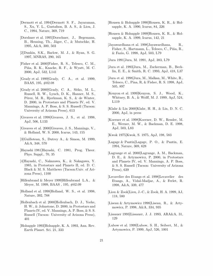
[Dermott et al. 1994]Dermott S. F., Jayaraman,S., Xu, Y. L., Gustafson, B. A. S., & Liou, J.C., 1994, Nature, 369, 719
[Dorshner et al. 1995]Dorschner, J., Begemann,B., Henning, Th., Jager, C., & Mutschke, H.1995, A&A, 300, 503
[2]Dunkin, S.K., Barlow, M. J., & Ryan, S. G.1997, MNRAS, 290, 165
[Fisher et al. 2000]Fisher, R. S., Telesco, C. M.,Pina, R. K., Knacke, R. F., & Wyatt, M. C.2000, ApJ, 532, L141
[Grady et al. 1999]Grady, C. A., et al. 1999,BAAS, 195, #02.08
[Grady et al. 2000]Grady, C. A., Sitko, M. L.,Russell, R. W., Lynch, D. K., Hanner, M. S.,Perez, M. R., Bjorkman, K. S., & de Winter,D. 2000, in Protostars and Planets IV, ed. V.Mannings, A. P. Boss, & S. S. Russell (Tucson:University of Arizona Press), 613
[Greaves et al. 1998]Greaves, J. S., et al. 1998,ApJ, 506, L133
[Greaves et al. 2000]Greaves, J. S., Mannings, V.,& Holland, W. S. 2000, Icarus, 143, 155
[3]Guilloteau, S., Dutrey A., & Simon, M. 1999,A&A, 348, 570
[Hayashi 1981]Hayashi, C. 1981, Prog. Theor.Phys. Suppl., 70, 35
[4]Hayashi, C., Nakazawa, K., & Nakagawa, Y.1985, in Protostars and Planets II, ed. D. C.Black & M. S. Matthews (Tucson:Univ. of Ari-zona Press), 1100
[Hillenbrand & Meyer 1999]Hillenbrand L.A., &Meyer, M. 1999, BAAS , 195, #02.09
[Holland et al. 1998]Holland, W. S., et al. 1998,Nature, 392, 788
[Hollenbach et al. 2000]Hollenbach, D. J., Yorke,H. W., & Johnstone, D. 2000, in Protostars andPlanets IV, ed. V. Mannings, A. P. Boss, & S. S.Russell (Tucson: University of Arizona Press),401
[Holsapple 1993]Holsapple, K. A. 1993, Ann. Rev.Earth Planet. Sci. 21, 333
[Housen & Holsapple 1990]Housen, K. R., & Hol-sapple, K. A. 1990, Icarus, 84, 226
[Housen & Holsapple 1999]Housen, K. R., & Hol-sapple, K. A. 1999, Icarus, 142, 21
[Jayawardhana et al. 1998]Jayawardhana, R.,Fisher, S., Hartmann, L., Telesco, C., Pina, R.,& Fazio, G. 1998, ApJ, 503, L79
[Jura 1991]Jura, M. 1991, ApJ, 383, L79
[Jura et al. 1993]Jura, M., Zuckerman, B., Beck-lin, E. E., & Smith, R. C. 1993, ApJ, 418, L37
[Jura et al. 1998]Jura, M., Malkan, M., White, R.,Telesco, C., Pina, R, & Fisher, R. S. 1998, ApJ,505, 897
[Kenyon et al. 1999]Kenyon, S. J., Wood, K.,Whitney, B. A., & Wolff, M. J. 1999, ApJ, 524,L119
[Klahr & Lin 2000]Klahr, H. H., & Lin, D. N. C.2000, ApJ, in press
[Koerner et al. 1998]Koerner, D. W., Ressler, M.E., Werner, M. W., & Backman, D. E. 1998,ApJ, 503, L83
[Kwok 1975]Kwok, S. 1975, ApJ, 198, 583
[Lagage & Pantin]Lagage, P. O., & Pantin, E.1994, Nature, 369, 628
[Lagrange et al. 2000]Lagrange, A. M., Backman,D. E., & Artymowicz, P. 2000, in Protostarsand Planets IV, ed. V. Mannings, A. P. Boss,& S. S. Russell (Tucson: University of ArizonaPress), 639
[Lecavelier des Etangs et al. 1998]Lecavelier desEtangs, A., Vidal-Madjar, A., & Ferlet, R.1998, A&A, 339, 477
[Liou & Zook]Liou, J.-C., & Zook, H. A. 1999, AJ,118, 580
[Liseau & Artymowicz 1998]Liseau, R., & Arty-mowicz, P. 1998, A&A, 334, 935
[Lissauer 1993]Lissauer, J. J. 1993, ARA&A, 31,129
[Lubow et al. 1999]Lubow, S. H., Seibert, M., &Artymowicz, P. 1999, ApJ, 526, 1001
21

[Meyer & Beckwith 2000]Meyer M. R., & Beck-with, S.V.W. 2000, in ISO Surveys of a DustyUniverse, ed. D. Lemke, M. Stickel, & K. Wilke(Heidelberg: Springer-Verlag), in press
[Natta et al. 2000]Natta, A., Grinin, V. P., &Mannings, V. 2000, in Protostars and PlanetsIV, ed. V. Mannings, A. P. Boss, & S. S. Russell(Tucson: University of Arizona Press), 559
[Osterloh & Beckwith 1995]Osterloh, M., & Beck-with, S. V. W. 1995, ApJ, 439, 288
[Ozernoy et al. 2000]Ozernoy, L. M., Gorkavyi, N.N., Mather, J. C., & Taidakova, T. A., 2000,ApJ, 537, L147
[Pantin et al. 1997]Pantin, E., Lagage, P. O., &Artymowicz, P. 1997, A&A, 327, 1123
[Roques et al. 1994]Roques, F., Scholl, H.,Sicardy, B., & Smith, B. A. 1994, Icarus, 108,37
[Schneider et al. 1999]Schneider, G., et al. 1999,ApJ, 513, L127
[Stauffer et al. 1995]Stauffer, J. R., Hartmann, L.W., & Barrado y Navascues, D. 1995, ApJ, 454,910
[Sylvester et al. 1996]Sylvester, R. J., Skinner, C.J., Barlow, M. J., & Mannings, V. 1996, MN-RAS, 279, 915
[Telesco et al. 2000]Telesco, C. M., et al. 2000,ApJ, 530, 329
[van den Ancker et al. 1998]van den Ancker, M.E., de Winter, D., & Tjin A Djie, H. R. E.1998, A&A, 330, 145
[Weidenschilling 1977]Weidenschilling, S. J. 1977,MNRAS, 180, 57
[Weinberger 1999]Weinberger, A. J., Becklin, E.E., Schneider, G., Smith, B. A., Lowrance, P.J., Silverstone, M. D., Zuckerman, B., & Ter-rile, R. J. 1999, ApJ, 525, L53
[Wyatt et al. 1999]Wyatt, M. C., Dermott, S. F.,Telesco, C. M., Fisher, R. S., Grogan, K.,Holmes, E. K., & Pina, R. K. 1999, ApJ, 527,918
[Zuckerman et al. 1995]Zuckerman, B., Forveille,T., & Kastner, J. H. 1995, Nature, 373, 494
[Zuckerman & Becklin 1993]Zuckerman, B., &Becklin, E. E. 1993, ApJ, 414, 793
AAS LATEX macros v5.0.
22

Table 1
Model Parameters.
Model Star Mg(M⊕) rout(AU) p Cout K Md(M⊕) Ld/L
1 HR4796A 10 100 −2.25 1.05 1× 10⁻⁹ 0.90 1.7× 10⁻²
2 · · · 1 · · · · · · · · · · · · 0.10 2.0× 10⁻³
3 · · · · · · · · · −2.75 · · · · · · 0.37 8.2× 10⁻³
4 · · · · · · · · · −1.25 · · · · · · 3.10 4.2× 10⁻²
5 · · · · · · · · · · · · 2.0 · · · 0.72 1.4× 10⁻²
6 · · · · · · · · · · · · · · · 2× 10⁻⁸ 0.05 9.1× 10⁻⁴
7 · · · 4 80 · · · · · · · · · 0.31 8.2× 10⁻³
8 HD141569A 50 370 · · · · · · · · · 4.23 1.1× 10⁻²
Note.—Blanks mean that the same value as model 1 is used. See §6.1 for the definition of K and§7.1 for Md and Ld.
23
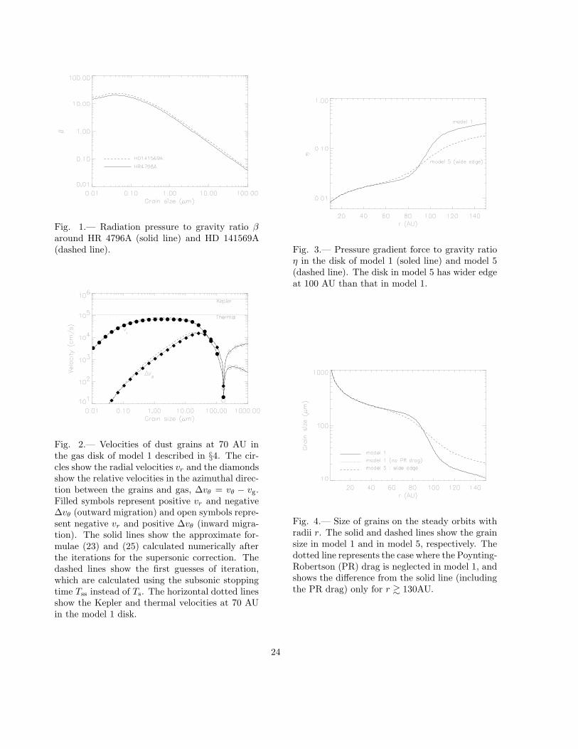
Fig. 1.— Radiation pressure to gravity ratio βaround HR 4796A (solid line) and HD 141569A(dashed line).
Fig. 2.— Velocities of dust grains at 70 AU inthe gas disk of model 1 described in §4. The cir-cles show the radial velocities vr and the diamondsshow the relative velocities in the azimuthal direc-tion between the grains and gas, ∆vθ = vθ − vg.Filled symbols represent positive vr and negative∆vθ (outward migration) and open symbols repre-sent negative vr and positive ∆vθ (inward migra-tion). The solid lines show the approximate for-mulae (23) and (25) calculated numerically afterthe iterations for the supersonic correction. Thedashed lines show the first guesses of iteration,which are calculated using the subsonic stoppingtime Tss instead of Ts. The horizontal dotted linesshow the Kepler and thermal velocities at 70 AUin the model 1 disk.
Fig. 3.— Pressure gradient force to gravity ratioη in the disk of model 1 (soled line) and model 5(dashed line). The disk in model 5 has wider edgeat 100 AU than that in model 1.
Fig. 4.— Size of grains on the steady orbits withradii r. The solid and dashed lines show the grainsize in model 1 and in model 5, respectively. Thedotted line represents the case where the Poynting-Robertson (PR) drag is neglected in model 1, andshows the difference from the solid line (includingthe PR drag) only for r & 130AU.
24

Fig. 5.— (a) Evolution of the orbital radii r of8−300µm grains in the disk of model 1. The massof the gas disk is 10M⊕. The time is measuredby the orbital period at 100AU, Pout. The grainsare generated at 10 AU and move outward untilarriving at the steady orbits. The oscillations of rof 8µm and 20µm grains are due to the excitationof their orbital eccentricities at the edge of the gasdisk. (b) The same as Fig. 5(a), but for model 2where the gas disk is 1M⊕.
Fig. 6.— Evolution of the orbital elements of (a)an 8µm grain and (b) a 100µm grain. The gas diskis that in model 1. Arrows show the directions ofthe orbital evolution obtained by the perturbationequations (Gauss’s equations). The length of ar-rows is set to be constant and does not representthe evolution rate. The circles show the evolu-tion of orbital elements of test particles, whichare obtained directly by the orbital calculations.The initial values of the test particles’ orbital el-ements are (a) a = 100AU and e = 0.05 and (b)a = 100AU and e = 0.5. The circles are plotteduntil t = 1000Pout with the logarithmic time in-terval: the first time interval is 0.01Pout and eachtime interval is 1.2 times the previous one.
25

Fig. 7.— Distances of the apocenter and pericen-ter of the grains’ orbits from the central star. Thegrains are generated at 10 AU and the orbits att = 1000Pout are shown by the solid line (in thegas disk with 10M⊕; model 1) and dashed line(in the gas disk with 1M⊕; model 2). The orbitsof grains larger than about 10µm are circular andthe distances of the apocenter and pericenter coin-cide with the value derived by the condition β = η(dotted line).
Fig. 8.— Life and migration time of dust grains.The solid line shows the life time of grains onthe steady orbits under the collisional destruction.The dashed line shows the migration time from10AU to the 99% of the radius of the steady or-bits. (a) The gas mass is Mg = 10M⊕ (model 1).(b) Mg = 1M⊕ (model 2).
26

Fig. 9.— Optical depth in the vertical directionof the dust disks. The optical depth is calculatedusing the geometrical cross sections of grains. (a)For various disk masses, Mg. the solid and dashedlines show the optical depth of the dust in thegas disk of 10M⊕ (model 1) and 1M⊕ (model 2),respectively. (b) For various profiles of gas den-sity, p, where ρg ∝ rp. The dotted, solid anddashed lines correspond to p = −1.25 (uniformsurface gas density; model 4), p = −2.25 (model1) and p = −2.75 (model 3), respectively. (c)For various width of the edge of gas disks. Thesolid and dashed lines correspond to the narrowedge (Cout = 1.05; model 1) and the wide edge(Cout = 2.0; model 5), respectively. (d) For vari-ous strength of dust grains. The solid and dashedlines correspond to the rocky grains (K = 1×10⁻⁹;model 1) and the icy grains (K = 2×10⁻⁸; model6), respectively.
Fig.9 — continued.
Fig. 10.— Simulated image of the model 4 diskin the scattered light and the thermal emission.The gray scale shows the scattered light flux in1.1µm with linear spacing. The contours show thethermal flux in 18.2µm and are spaced linearly.The unit of contour levels is arbitrary. The diskhas a constant surface gas density with an edgeat 100 AU, viewed in 60 from pole-on. The fluxis calculated for r ≥ 13AU (outside the artificialhole at the center).
27