dyn manual
DESCRIPTION
Dynabrade Power Tools ManualTRANSCRIPT

DYNABRADE®
Industrial Abrasive
Power Tools

DYNABRADE®
IntrIntroduction oduction to Dynabradeto Dynabrade
√ Success since 1969
√ Manufacturer of Industrial QualityAbrasive Power Tools
√ All Dynabrade tools are designedto run abrasive products
√ Incentives for Distributors:• Top-Quality Product Line• Consumables and Parts
mean Repeat Business!
2

Dynabrade’Dynabrade’ssGlobal DistributionGlobal Distribution√ Our distribution network sells
to a variety of industries:• Metalworking• Woodworking• Solid Surface• Fiberglass• Automotive Manufacturing• Automotive Aftermarket
√ We are here to sell theentire product line!
DYNABRADE®
3
Dynabrade’Dynabrade’ssCommitment toCommitment to
SERSERVICVICEE !!In order to compete in today’s
market, we must provide our
distribution with quality product
and QUALITY SERVICE!
DYNABRADE®
4

DYNABRADE®
5
DynabradeDynabradeInnovationInnovation
√ We consider innovation to beone of the keys to our success
√ Dynabrade is constantly introducingnew products to the marketplace
√ We work with abrasive manufacturers such as 3M, to develop tools which correctlyutilize abrasives

DYNABRADE®
6
DynabradeDynabradeErErgonomicsgonomics
We design our tools by addressingfour key ergonomic concerns,
which we call V V I N :• Vacuum • Insulation• Vibration • Noise
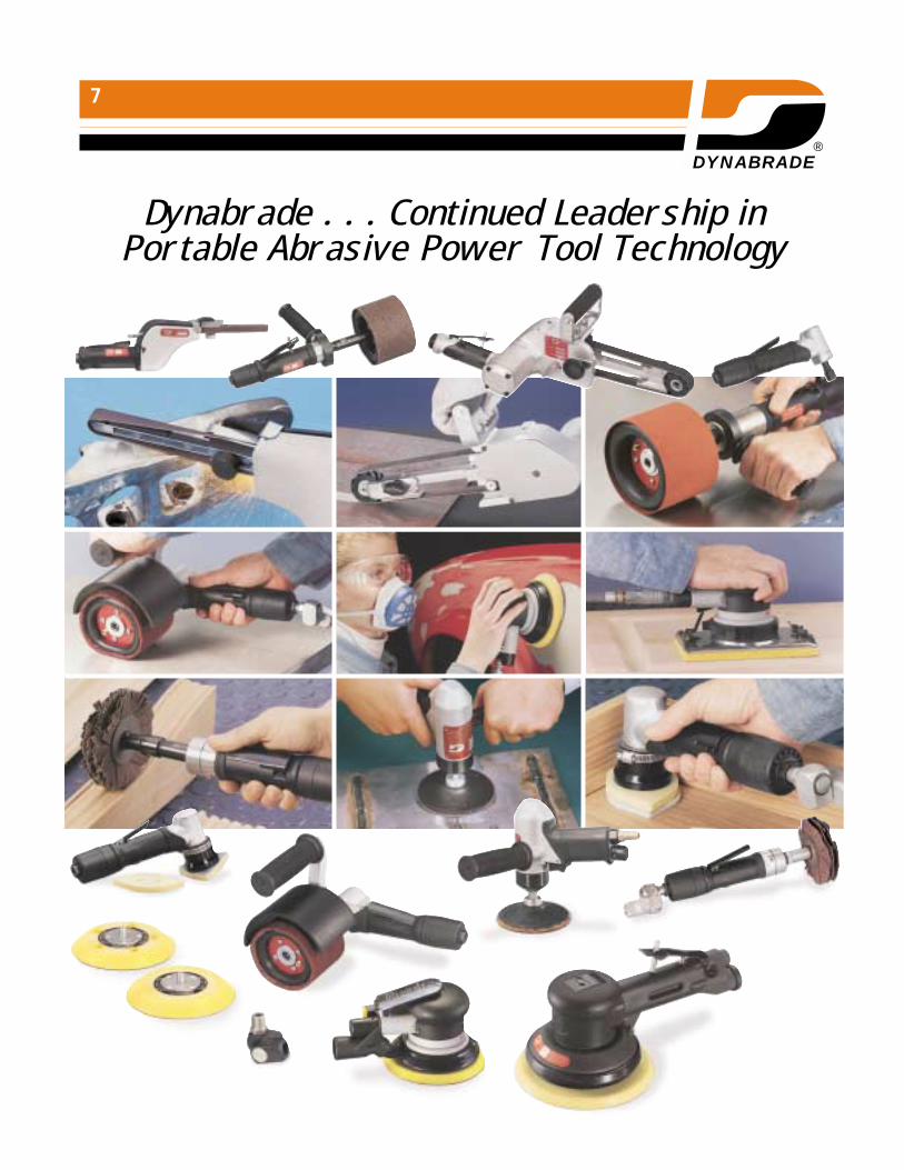
Dynabrade . . . Continued Leadership in Portable Abrasive Power Tool Technology
DYNABRADE®
7

DYNABRADE®
QualifyQualifyYYour Customer!our Customer!Start with 3 basic questions:
√ Which abrasive applications do you perform?(Such as grinding, polishing, sanding, finishing, deburring, graining, cleaning, etc.)
√ What kind of tools are you using?(Electric, pneumatic, hand, stationary,portable, etc.)
√ What concerns or problemsexist with your current method?(Takes too long, too messy, machine damage,operator discomfort, abrasive cost, etc.)
8

DYNABRADE®
Ask Relevant Questions1.) What type of compressor do you have?
How much horsepower does it generate?Screw, piston, big, small, old new, etc.?
2.) May I see your set-up?Look for:
• Plug type • Dust• Air hose size • Competition / Brand name• Air leaks
3.) Are your workers/operators satisfied withthe comfort level of your current tools?
• Too heavy? • Noisy?• Too cold? • Hard to handle?• Vibrate? • Frequent breakdown?
4.) May I quickly check a few things?• Use gauge to check available pressure• Check air line set-up (dead end or loop?)
Your customer will begin to see you as a “Professional!”
9

DYNABRADE®
DynabradeSalesman’s Checklist
1.) Pressure Gauge• Minimum 90 PSI (6.2 Bars)• Threaded “T” Piece • Teflon Tape
2.) Assorted Plugs & Couplers• Male & Female Plugs
3.) Hand Tools• Shifting Spanners • Dynabrade Open Wrenches• Screwdrivers • Blade• Assorted Hex Wrenches (Allen Keys)
4.) Sales Literature• Catalogs • Brochures (languages needed)• Promotional Flyers • Product Info
5.) Pricing Information• Tools • Accessories• Promotions (if any) • Related items (abrasives, etc.)
10

DYNABRADE®
Demo,Demo, Demo,Demo, Demo!Demo!The only way to sell a Dynabrade tool
is to DEMONSTRATE it!
The best way to demonstrate the tool is to let the OPERATOR run it!
Ask the operator to note these features:• Lightweight
• Comfortable
• Quiet when running
• WARM - not cold!
For a successful demo, always:• Ensure that the abrasive is correct
• Ask the operator if he has any concerns
• Remind the operator that the Dynabrade toolis part of a complete SYSTEM
• Explain that we offer full technical support
• Take your time!!
11

DYNABRADE®
12
Advantages ofAdvantages ofAirAir MotorsMotors overover
ElectricElectricAir Motor Electric Motor
Air motors run cool Windings in motors heat up
Air motors rarely break Electric motors can break down suddenly. Usually down suddenly
wear slowly, allowing easyplanning of maintenance
Can be stalled indefinitely Stalled electric motor withoutwithout motor damage overload protection can
quickly burn out
Generally lightweight Generally the heaviest and compact in size and bulkiest type of tool
Generally safe for even Shock hazard; more suitedunskilled workers to use for use by special craftsmen

DYNABRADE®
13
PrPreventativeeventativeMaintenancMaintenancee
√ Air must be clean. Use an air line filter-separator. Clean or replace filter element periodically.
√ Lubricate air motor properly.Use a filter-regulator-lubricator; follow manufacturer’s recommendations for proper usage of oil.
√ Check for air pressure drop.Bends in air hose can result in significant loss of air pressure.
√ Select the right air motor for the job.Motor should provide the needed horsepower or torque by using only two-thirds of available line pressure.

DYNABRADE®
14
Air MotorAir MotorTTrroubleshootingoubleshooting
GuideGuide
Dirt, ForeignMaterial X X X
Internal Rust X X X
Misalignment X X X X X
InsufficientAir Pressure X X
Air Line too small X
Restricted Exhaust X X
Poor Lubrication X X X X
Jammed Machine X X X X
Small Compressor X X
Compressor too far from tool X X
Result
CauseLow Low Won’t Runs Runs, then
Torque Speed run at all Hot slows down

DYNABRADE®
Tool PerformanceHorsepower - is a function of Torque x Speed / Constant
Air Flow - as the flow increases the pressure decreases
Efficiency - the more efficient the motor design, the greater the performance (in other words).
Reducing the amount of losses in air flow will increase the performance
Features of a tool design that affect performance:
15
DECREASEPERFORMANCE:
Increased clearances between mating parts
Too small or too longan air supply line
Small diameter motors that normally run at high speed,
that are choked down to lessthan 50% of their proper
output speed
INCREASEPERFORMANCE:
Precision machined tolerances
Proper air flow
Gearing
DYNABRADE®
Compressed Air Distribution System:Six General Rules
1. Pipe Sizes: Pipe sizes should be long enough that the pressure drop between the receiver and the point of use will not exceed 10 percent of the initial pressure. Fittingoffering the least amount of resistance to flow, such as long-radius elbows and maximum air flow connections, should be selected. Provisions should be made not only for present requirements but also for reasonable future growth.
2. Loop System: Where it is possible, a loop system around the plant within each shopand building is recommended. This gives a two-way distribution system to the pointwhere air demand is the greatest. The loop pipe should be large enough that the pressure drop will not be excessive at any outlet regardless of the direction of flow around the loop.
3. Distribution System: Long distribution lines, including those in a loop system, should have receivers of a liberal size located near the far end or at the points of heavy use. Many peak demands for air are of a short duration, and storage capacitynear such points avoids excessive pressure drop and may permit the use of a smaller compressor.
4. Point of Use: Each header or main should be provided with outlets as close as possible to the point of application. This permits the use of shorter hose lengths andavoids large pressure drops through the hose. Outlets should always be taken from the top of the pipeline to prevent carryover of condensed moisture to tools.
5. Piping: All piping should be sloped so that it drains toward a drop leg or moisture trap in order that condensation may be removed to prevent its reaching air-operated devices in which it would be harmful. The slope of the line should always be away from the compressor to prevent flow back into the compressor cylinder. A slope of about 1/4" per foot (2.0 mm/m) may be used, with drains provided at all low points. These may consist of a short pipe with a trap or drain at the bottom.
6. Distribution System: For a system using only oil-free compressors, it is strongly recommended that corrosion-resistant pipe be used. Unlike a system using lubricat-ed compressors in which an oil film will form to protect the pipe from the corrosive effect of the moisture in the air, a non-lubricated system will experience corrosion. This corrosion can lead to contamination of products and control systems.
16

17
DYNABRADE®
Dead
End
Syst
em
Loop
Syst
em
Dead
End
vs.
Loo
p Sy
stem

18
DYNABRADE®
Air
Tool
Dra
in V
alve
Dra
in
Val
ve
To T
ool S
tatio
n
Air
Hos
eAir
Flo
w
Air
Flo
w
Air
Flo
w
Air
Com
pres
sor
and
Rec
eive
r
Ref
riger
ated
Air
Dry
er
Dra
inV
alve
Meg
a F
low
Plu
g/C
oupl
er
Meg
a F
low
Cou
pler
/Plu
g
Filt
erR
egul
ator
Lubr
icat
or
Clo
sed
Lo
op
Pip
e S
yste
m(S
lop
ed in
th
e d
irec
tio
n o
f ai
r fl
ow
)
Shu
t-O
ffV
alve
Shu
t-O
ffV
alve

Typi
cal L
ayou
t of a
Com
pres
sed
Air
Syst
em
Com
pres
sor
Filte
rR
ecei
ver
Dis
trib
utio
nPo
int o
f Use
FRL
Use
rA
fterc
oole
rsTa
nkSy
stem
Wor
ksta
tion
Dry
ers
19
Alw
ays
chec
k ai
r pre
ssur
e at
Use
r (To
ol) r
athe
r tha
n th
e Fi
lter-R
egul
ator
-Lub
ricat
or.
See
char
t abo
ve.
Mos
t air
pres
sure
dro
ps w
ill oc
cur b
etw
een
thes
e tw
o po
ints
.
Inco
rrect
air
hose
siz
e ca
n re
stric
t air
flow
to th
e to
ol,
redu
cing
the
tool
’s e
ffici
ency
.
Air H
ose
“Rul
e of
Thu
mb”
:
0 - 2
5 SC
FM. .
. . .
. . 1
/4" I
.D. L
ine
26 -
45 S
CFM
. . .
. . .
3/8"
I.D
. Lin
e
46 -
70 S
CFM
. . .
. . .
1/2"
I.D
. Lin
e
Thin
gs to
Con
side
r:St
anda
rd C
ubit
Feet
Per
Min
ute
(SC
FM) o
r Sta
ndar
dM
eter
s pe
r Min
ute
(SM
PM) o
f com
pres
sor o
utpu
t is
mor
eim
porta
nt th
an c
ompr
esso
r siz
e (H
orse
pow
er/W
atts
). T
his
is b
ecau
se s
ome
com
pres
sor m
odel
s ar
e m
ore
effe
ctiv
e at
pro
duci
ng a
ir th
an o
ther
s.
One
hor
sepo
wer
(745
.7 W
) of c
ompr
esso
r will
prod
uce
appr
oxim
atel
y 3.
8 SC
FM o
f air
at 9
0 PS
I. D
ivid
ing
air
flow
rate
by
3.8
will
give
an
estim
ate
of w
hat s
ize
com
pres
sor i
s ne
eded
.
Exam
ple:
570
15 R
ando
m O
rbita
l San
der
uses
16
SCFM
of a
ir at
90
PSI.
16 d
ivid
ed b
y 3.
8 =
4.21
; rou
nd u
p to
5
Ther
efor
e, a
5 H
Pco
mpr
esso
r will
be n
eede
d to
run
one
5701
5 R
OS
at fu
ll (1
00%
) dut
y cy
cle
(per
cent
age
of ti
me
the
tool
will
be u
sed)
.
DYNABRADE®

DYNABRADE®
Flow Rate (SCFM) 16 (R.O.S.)
10 20 40 100
ø1/4" 6.6 13.3 26.6 66.5
ø3/8" 0.9 1.8 3.5 8.8
ø1/2" 0.2 0.4 0.8 2.1
ø3/4" 0.0 0.1 0.1 0.3
ø1" 0.0 0.0 0.0 0.1
ø1.5" 0.0 0.0 0.0 0.0
ø2" 0.0 0.0 0.0 0.0
ø3" 0.0 0.0 0.0 0.0
Flow Rate (SCFM) 32 (0.7 HP)
10 20 40 100
ø1/4" 26.6 53.2 106.3 265.8
ø3/8" 3.5 7.0 14.0 35.0
ø1/2" 0.8 1.7 3.3 8.3
ø3/4" 0.1 0.2 0.4 1.1
ø1" 0.0 0.1 0.1 0.3
ø1.5" 0.0 0.0 0.0 0.0
ø2" 0.0 0.0 0.0 0.0
ø3" 0.0 0.0 0.0 0.0
20
Flow Rate (SCFM) 45 (1.2 HP)
10 20 40 100
ø1/4" 52.6 105.1 210.3 525.7
ø3/8" 6.9 13.8 27.7 69.2
ø1/2" 1.6 3.3 6.6 16.4
ø3/4" 0.2 0.4 0.9 2.2
ø1" 0.1 0.1 0.2 0.5
ø1.5" 0.0 0.0 0.0 0.1
ø2" 0.0 0.0 0.0 0.0
ø3" 0.0 0.0 0.0 0.0
Flow Rate (SCFM) 75 (2.0 HP)
10 20 40 100
ø1/4" 146.0 292.0 584.1 1460.2
ø3/8" 19.2 38.5 76.9 192.3
ø1/2" 4.6 9.1 18.3 45.6
ø3/4" 0.6 1.2 2.4 6.0
ø1" 0.1 0.3 0.6 1.4
ø1.5" 0.0 0.0 0.1 0.2
ø2" 0.0 0.0 0.0 0.0
ø3" 0.0 0.0 0.0 0.0
Loss of Air Pressure (PSI)Due to Friction
constant. . . . . . . . . . . 0.065
pressure . . . . . . . . . . . . . 90
Cr . . . . . . . . . . . . . 7.122449 Calculated