dynamic aeroelastic behavior of key words: aeroelasticity
TRANSCRIPT
Proceedings of the 8th ASAT Conference, 4-6 May 1999 Paper SM-01 175
Military Technical College Kobry Elkobbah,
Cairo, Egypt
41011‘ Elm International Conference A S A 'PE on Aerospace Sciences &
NNO Aviation Technology
DYNAMIC AEROELASTIC BEHAVIOR OF
SLENDER COMPOSITE SWEPT WLNGS
Wael G. Abdelrahmanl
Hani M. Negm2
Key Words: Aeroelasticity, Wing, Sweep, Composite, Flutter, Dynamic, Critical
Speeds, Equivalent Plate, Incompressible Flow.
ABSTRACT
The aim of this work is to study the dynamic aeroelastic behavior of slender composite swept wings using a modified equivalent plate approach. The present modified analysis incorporates transverse shear deformation and satisfies the shear stress conditions, which significantly improves the accuracy of thick wing results. This , analysis is used to study the problem of flutter of several slender, composite wings having different aspect ratios, taper ratios, sweep angles, numbers of layers and fiber orientations. Comparisons and conclusions regarding the influence of the above parameters on the wings' dynamic aeroelastic performance are presented. All analyses are confined to the incompressible flow regime.
1. INTRODUCTION
All critical speeds [1-3] of composite wings were found to improve by wise
selection of wing structural parameters. Thi.s fact is the basis of what is known as
aeroelastic tailoring [4]. Many efforts have been made in the last two decades to
study and improve aeroelastic characteristics of composite wings.
1. Assistant lecturer, Aerospace Engineering Dept., Cairo University. 2. Professor of Aircraft Structures, Aerospace Engineering Dept., Cairo University.
Proceedings of the eh ASAT Conference, 4-6 May 1999 Paper SM-01 176
The Wing Aeroelastic Synthesis Procedure (TSO) developed at General
Dynamics-Fort Worth during the early 1970's is a preliminary design tool which
employs a Ritz equivalent plate model of the wing. The flutter and Strength
Optimization Procedure (FASTOP) is also a finite element-based two-step design
procedure developed for the same purpose.
Green [5] used an integrating matrix method to solve the fourth-order
differential equation representing the aeroelastic behavior of a high aspect ratio
swept-back wing. In his analysis he used an anisotropic plate beam model and
neglected transverse shear effects. Chen, Dugundji and Dunn [6, 7] conducted
intensive theoretical and experimental investigations on graphite/epoxy cantilever
forward-swept wings. The mathematical flutter model was formulated using
Rayleigh-Ritz method. Librescu and Simovich [8] formulated a closed-form
solution for the divergence problem of composite swept wings taking the effect of
warping restraint at the wing root into consideration. They used a simple beam
model for structural modelling and the classical aerodynamic strip theory to
calculate aerodynamic loads. Liu et al [9] investigated flutter of cantilever
composite plates in subsonic flow.
An attempt to investigate the sensitivity of divergence speed, spanwise lift
distribution and induced drag of composite wings to several shape parameters was
made by Barthelemy and Bergen [10]. The structural response was obtained using
the equivalent plate method, and the aerodynamic response was predicted using
Weissinger's L-method. Vanderplaats and Weisshaar [11] showed how the
addition of aeroelastic stiffness constraints to wing optimization problems leads to
significant increases in the wing weight.
Proceedings of the 8th ASAT Conference, 4-6 May 1999 Paper SM-01 177
Several complexities were added to aeroelastic models representing aircraft
wings to make them closer to real wings. For example, Lottati [12] investigated the
effect of adding fuselage weight at the wing semispan and pylon weight at the
wing tip on the aeroelastic characteristics of the airplane as an unconstrained
vehicle. Recently, Koo and Lee [13] incorporated the effect of structural damping
in their study of flutter of swept plate wings. The wing structure was modeled by
the finite element method using shear deformable laminated plate elements, while
the doublet-point method was used to predict the three-dimensional unsteady
aerodynamic forces acting on the oscillating wing. The present authors
investigated the static aeroelastic behavior of composite swept wings using a
modified equivalent plate approach based on a higher-order shear deformation theory [14].
2. EQUIVALENT PLATE MODELING OF COMPOSITE WINGS
The term "equivalent plate" is used to describe an aircraft wing modeling
technique in which all the'displacement functions and wing geometry are functions
of the coordinates in the wing reference plane in a manner similar to that of plate
problems. In this technique, the Rayligh-Ritz method is used to obtain an
approximate solution to he variational condition on the total potential energy of
the wing structure and applied loads. The total energy E associated with the analytical model used is:
E = U— Wext —T (1) 'where U is the strain energy of the structure, We. is the work done by external loads, and T is the kinetic energy of the structure.
These energy terms can be expressed as functions of the wing deflections
which, in turn, can be expressed in terms of a set of specified displacement

Proceedings of the 8th ASAT Conference, 4-6 May 1999 Paper 3M-01 178
functions that satisfy the boundary conditions at the root. The Ritz minimization
technique requires that E have a stationary value, a condition that is used to
&telinine the contribution of each displacement function to the wing deflection.
An equivalent plate model based on the classical plate theory was first
suggested by Giles [15,16], which is capable of modeling sandwich wings.
Another first-order shear deformable equivalent plate model was suggested by
Livne [17]. The model is capable of representing both sandwich and box
composite wings of general planform. In reference [18], the present authors
developed an improved equivalent plate model based on a higher-order shear
deformation theory which satisfies the zero transverse shear stress condiTion. The
model is capable of taking the contributions of the wing skin, spar caps and spar
webs to the strain and kinetic energies into consideration. In this model, the wing
displacements u, v, w in the x, y, z directions are expressed as:
u(x, y, z) = uo(x, y) + z[0 - 4(w x + 0) / 3(h / z)2 I
v(x, y, z) = vo(x, y) + 4w - 4(w y, + / 3(h / z)2 (2)
w(x,y,z)=w0(x,y)
where 0 , yr are the rotations of the normals to the plate about the x and y axes,
and h is the plate thickness.
3. UNSTEADY AERoD YNAMICS OF SLENDER WINGS
Unsteady aerodynamic loads on slender wings can be reasonably
approximated by assuming 2-dimensional flow. This subject has been widely
treated in the literature; see for example references [1, 19, 20]. Starting from the
basic continuity and momentum equations, and assuming a velocity potential
function and harmonically oscillating airfoil, the lift and pitching moment can be
expressed in terms of airfoil parameters and a complex function C(k).

Proceedings of the Stn ASAT Conference, 4-6 May 1999
Paper SM-01 . 179
Smilg and Wasserman [19] defined the aerodynamic forces for the case of
aileron overhang and unsealed gap in terms of several T- and (1)- functions. Their
results for the lift and twisting moment per unit span are cast in the form:
L' = 7z-pb3coiLh -- + [La - (11 2 + a)Lh]a + - (c - e)L:13} (3)
ELI '= 7rpb4a): x
- (1 / 2 -a)Lh]-6:h +[M - (1 / 2 + a)(L. Mb) + (1 / 2 +cr)'-Lida (4)
+ [M,8 - (1/ 2 + a)Lo - (c - e)M: + (c - e)(1/ 2 +a)L,,k3
where all geometric and aerodynamic coefficients are defined in the above
references. Figs. (1) and (2) show the cross section and planform of slender swept
wings and their important parameters.
4. WING FLUTTER
The total vertical surface displacement is given by: w (x, y, t) = w b(y ,t) xe(y,t)
The bending and twisting functions wb(y,t) and 6(y,t) can be cast in the form: w b(y ,t) = w R(t) f (y)
0(y,t)= OR (t)g(y)
where WR(t) and OR(t) are the bending and twisting displacements of a reference
wing station, normally selected at 0.75 the half span, and f(y) and g(y) are
preselected functions which satisfy the root boundary conditions.
Substituting into the equations of motion [1] we get:
r mf 2dy - J Safgdy+wRvc),2(1+ igd )f mf 2dy = J Lfdy
(5)

Proceedings of the eh ASAT Conference, 4-6 May 1999 Paper SM-01 180
z
U
Fig. 1 Geometry of a typical airfoil used in unsteady aerodynamics.
Fig. 2 Slender swept wing with spanwise and streamwise segmen:s.
Proceedings of the 8th ASAT Conference, 4-6 May 1999 Paper SM-01 181
1 1 e.112 lag2dy — 1;l112 J Scfgdy + EIRcoa2(1+ igd )1 lagd 2dy = Mgdy (6)
0 0 0 0 where ga is the damping coefficient, assumed to be equal in the bending and the
torsional modes. Assuming simple harmonic variation of h and a, we get the
flutter eigenvalue problem. This problem can be solved by several methods, among
which we choose the U-g method [1].
The above flutter model is applied to the same slender wing of Fig. (2).
Flutter speeds ant. calculated for several composite wings having sweep angles 30° and -30°, and, ply orientations ranging between 0° and 180° (21]. Results are
plotted in Figs. (3) and (4). Inspection of the figures leads to the conclusion that certain rhily orientations increase flutter speed while others decrease flutter speed
for erAch wing sweep angle, and that for each wing sweep angle, there are certain
ply orientations in which flutter ceases to occur, because the divergence speed is lower than the flutter speed.
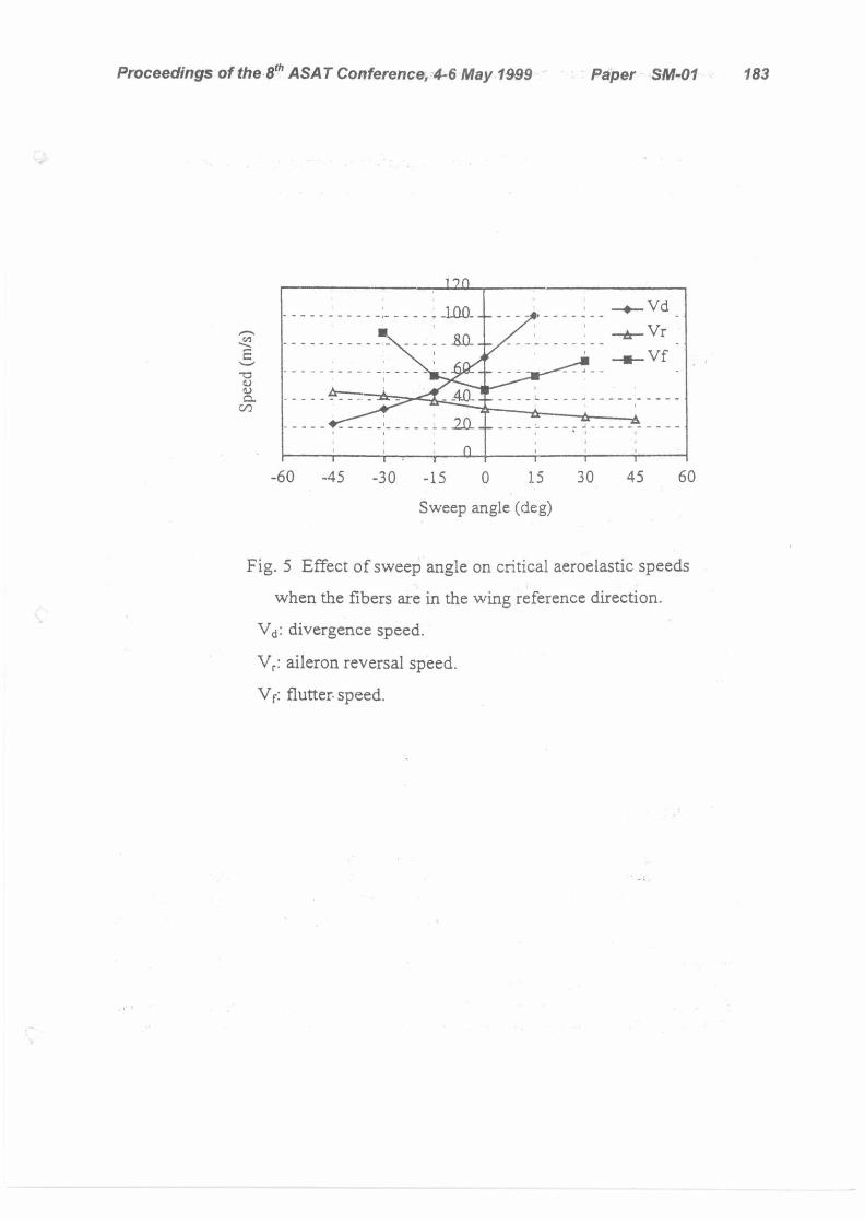
Finally, the general effect of wing sweep on the critical aeroelastic speeds
when the principal material stiffness direction coincides with the wing reference
direction is indicated in Fig. (5).
5. CONCLUSIONS
The present work deals with the dynamic aeroelastic performance of
composite swept wings. The investigation involves the development of an efficient
structural model based on the equivalent plate technique, and a 2-dimensional
unsteady aerodynamic model based on the Smilg and Wasserman approximation.

Proceedings of the 8th ASAT Conference, 4-6 May 1999 Paper SM-01 182
100 Fl
utte
r spe
ed (m
/s)
0 r
0 30 60 90 120 150
180
Ply angle (deg)
Fig. 3 Variation of flutter speed with ply angle
for a [8/0/0] swept-back cantilever wing.
AR: Wing aspect ratio.
TR: Wing thickness ratio.
A: Wing backward sweep angle.
120
100 AR=6 80 — - - _ _ TR=1
0.) 60 — A=-30 (1,
co" 40 [8/0/0] 20
0 0 30 60 90 120 150 180
Ply angle (deg)
Fig. 4 Variation of flutter speed with ply angle
for a [0/0/8] swept-forward cantilever wing.
Proceedings of the 8th ASA T Conference, 4-6 May 1999 Paper SSW-01 183
-60 -45 -30 -15 0 15 30 45 60
Sweep angle (deg)
. 5 Effect of sweep angle on critical aeroelastic speeds
when the fibers are in the wing reference direction.
Vd: divergence speed.
Vr: aileron reversal speed.
Vf. flutter, speed.
Proceedings of the 8th ASAT Conference, 4-6 May 1999 Paper SM-01 184
The structural model has been modified to improve the accuracy of thick
wing deflection calculations by incorporating shear deformations. Thus, it is
capable of modeling sandwich and box wing structures without discontinuities in
cross section or planform with an accuracy of about 3% in calculating deflections
and natural frequencies. It has the important advantage of small computational
time compared to current finite element models. Hence, it adopts itself to
preliminary aeroelastic design procedures in which both static deflections and
natural frequencies are repeatedly calculated.
The above structural and aerodynamic models are combined to solve the
problem of flutter of composite swept wings. This package was used to determine
the influence of various design parameters on the wing critical speed. Better still,
the package can be linked to an optimization routine to reach the optimum wing
design under given aeroelastic constraints. The ability to express wing planforin
and cross-section parameters in polynomial form greatly reduces the number of
design variables, and makes it possible to use efficient and powerful optimization
procedures.
REFERENCES
1. Bisplinghoff Raymond L., Ashley H. and Halfman Robert L., Aeroelasticity, Addison-Wesley Publishing Company, Cambridge 42, Mass., 1955.
2. Dowell Earl H., Curtiss Howard C., Scanlan Robert and Sisto Fernando, A Modern Course in Aeroelasticity, Kluwer Academic Publishers, Inc., Dordrecht, The Netherlands, 1989.
3. Bisplinghoff, R.L., and Ashley, H., Principles of Aeroelsticity, John Wiley and Sons, Inc., New York, 1962.
4. Shirk Michael H., Hertz Terrence J. and Weisshaar Terrence A., Aeroelastic Tailoring- Theory, Practice and Promise, J. Aircraft , Vol. 23, 6-18, 1986.
Proceedings of the 8th ASAT Conference, 4-6 May 1999 Paper SM-01 185
5. Green John A. Aeroelastic Tailoring of Aft-Swept High-Aspect-Ratio Composite Wings, J. Aircraft, Vol. 24, No. 11, 812-819, 1987.
6. Chen Gun-Shing and Dugundji J., Experimental Aeroelastic Behavior of Forward-Swept Graphite/Epoxy Wings with Rigid-Body Freedom, J. Aircraft, Vol. 24, No. 7, 454-462, 1987.
7. Dunn P. and Dugundji J., Nonlinear Stall Flutter and Divergence Analysis of Cantilevered Graphite/Epoxy Wings, AIAA Journal, Vol. 30, No. 1, 153-162, 1992.
8. Librescu L. and Simovich J., General Formulation for the Aeroelastic Divergence of Composite Swept-Forward Wing Structures, J. Aircraft, Vol. 25, No. 4, 364-371, 1988.
9. Lin K.J., Lu P.J. and Tarn J.Q., Flutter Analysis of Cantilever Composite Plates in Subsonic Flow, AIAA Journal, Vol. 27, 1102-1109, 1989.
10. Barthelemy Jean-Francois M. and Bergen Fred D., Shape Sensitivity Analysis of Wing Static Aeroelastic Characteristics, J. Aircraft, Vol. 26, No. 8, 71:2-717, 1989.
11. Vanderplaats G. N. and Weisshaar T. A., Optimum Design of Composite Structures, Int. J. Numer. Methods. Eng., Vol. 27, 437-448, 1989.
12. Lottati I., Aeroelastic Stability Characteristics of a Composite Swept Wing with Tip Weights for an Unrestrained Vehicle, J. Aircraft, Vol. 24, No. 11, 793-802, 1987.
13. Koo K. N. and Lee I., Aeroelastic Behavior of a Composite Plate Wing with Structural Damping, Computer & Structures, Vol. 50, 167-176, 1994.
14. Abdelrahman, W. G. and H. M. Negm, Static Behavior of Slender Composite Swept Wings, J. Eng. App. Sc., Cairo University, Vol. 44, 1997.
15. Giles G. L., Equivalent Plate Analysis of Aircraft Wing Box Structures with General Planform Geometry, J. Aircraft, Vol. 23, No. 11, 1986.
16. Giles G. Further Generalization of an Equivalent Plate Representation for Aircraft Structural Analysis, J. Aircraft, Vol. 26, No. 1, 1989.
17. Eli Livne, Equivalent Plate Structural Modeling for Wing Shape Optimization Including Transverse Shear, AIAA Journal, Vol. 32, No. 6, 1994.
18. Abdelrahman, W. G. and H. M. Negm, Analysis of Composite Swept Wing Structures, J. Eng. App. Sc., Cairo University, Vol. 44, 1997.
19. Smilg , B., and Wasserman, L.S., Application of Three-Dimensional Flutter Theory to Aircraft Structures, A.F.T.R. 4798, 1942.
20. Ueda. T. and Dowell E. H., A New Solution Method for Lifting Surfaces in Subsonic Flow, AIAA Journal, Vol. 20, 348-355, 1982.
21. Abdelrahman W., Static and Dynamic Behaviour of Composite Swept Wings, M.Sc. thesis, Aerospace Engineering Dept., Cairo University, 1995.