dynamic analysis of the gantry crane used for …
TRANSCRIPT

TRANSPORT PROBLEMS 2008 PROBLEMY TRANSPORTU Tom 3 Zeszyt 4 Część 2
Andrzej URBAŚ*, Stanisław WOJCIECH
University of Bielsko-Biała Willowa 2, 43-309 Bielsko-Biała, Poland *Corresponding author. E-mails: [email protected]
DYNAMIC ANALYSIS OF THE GANTRY CRANE USED FOR TRANSPORTING BOP
Summary. In the paper the dynamic analysis of a gantry crane used for transporting of
BOP (BlowOut Preventer) is presented. The crane is placed on a drilling platform. Sea waves cause motion of the platform and the load. Description of such systems can be used in the design process of control systems which allows us to compensate waving. Homogenous transformations and joint coordinates are used to describe behavior of the system. Equations of motion are derived using the Lagrange equations of the second order. In the paper the results of numerical calculations are presented as well.
ANALIZA DYNAMICZNA SUWNICY BRAMOWEJ PRZEZNACZONEJ DO TRANSPORTU BOP
Streszczenie. W pracy przedstawiono model dynamiczny suwnicy bramowej
przeznaczonej do transportu ładunku zwanego BOP (BlowOut Preventer). Suwnice tego typu montowane są na statkach lub platformach wiertniczych. Falowanie morza powoduje niepoŜądane ruchy ładunku, wpływające na pracę suwnicy. Podjęto zatem próbę opisu dynamiki układu, która umoŜliwiła zbadanie wpływu falowania na zachowanie układu. Do opisu zastosowano formalizm transformacji jednorodnych i współrzędne złączowe. Równania ruchu układu wyprowadzono stosując równania Lagrange’a II rodzaju. Przedstawiono wyniki symulacji numerycznych.
1. INTRODUCTION
Dynamic analysis of offshore systems mounted on platforms or vessels is especially difficult because it is necessary to consider phenomena connected with sea waves [1,3,5]. The waving causes additional motion of the base (platform) and thus there are impulse forces in the system which should be taken into account in the design process not only in stress analysis but also in design of drive and control systems.
In the paper homogenous transformations and joint coordinates are used to describe dynamic analysis of the gantry crane [2,6]. Equations of motion are formulated using the Lagrange equations of the second order.
2. MATHEMATICAL MODEL OF THE SYSTEM
The gantry crane (Fig. 1) is considered as a system with 12DoF (Fig. 2). The frame {F} is treated
as a rigid body (6DoF) connected with platform {D} by spring-damping elements (SDE). The load is
86 A. Urbaś, S. Wojciech also treated as a rigid body with 6DoF with respect to platform {D}. The load is connected with the
frame by means of two flexible ropes and additionally its motion in )(ˆ FX and )(ˆ FY directions is limited by guides.
a)
b)
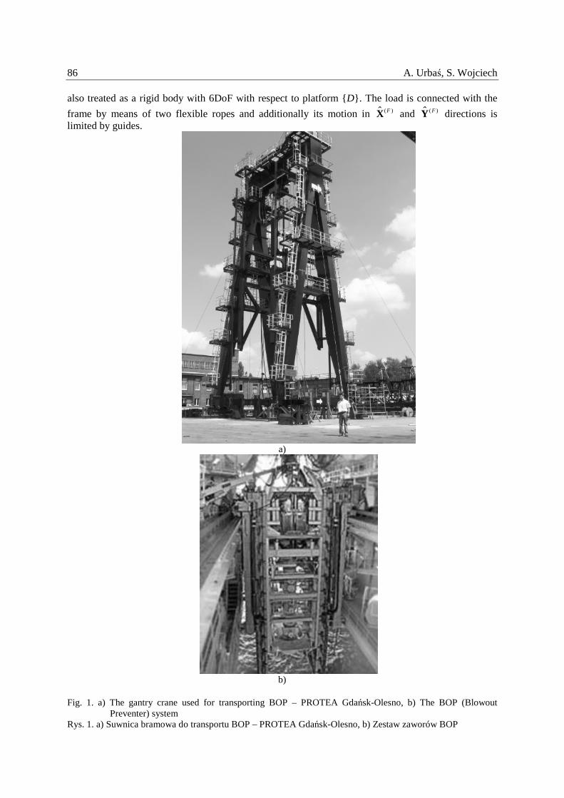
Fig. 1. a) The gantry crane used for transporting BOP – PROTEA Gdańsk-Olesno, b) The BOP (Blowout
Preventer) system Rys. 1. a) Suwnica bramowa do transportu BOP – PROTEA Gdańsk-Olesno, b) Zestaw zaworów BOP

Dynamic analysis of the gantry crane… 87
)(ˆ DX
)(ˆ DY
)(ˆ LZ
}{ F
1B
1A
2A
2B
)(ˆ LY
)(ˆ FY
)(ˆ LX
}{ L
)(ˆ FZ
)(Fθ
)(Fψ
)(Lθ
)(ˆ FX
)(Fϕ
)(ˆ DZ }{ D
)(Lψ
)(Dψ
)(Dθ
)(Lϕ
)(Dϕ
)(FC
)(LC
),,( )()()()( FC
FC
FC
F zyxC
),,( )()()()( LC
LC
LC
L zyxC
load (BOP) {L}
frame {F}
deck {D}
)0(X
)0(Z}0{
)0(Y
guides
heading angle
α)(Dy
)(Dx
)(Dz
Fig. 2. Model of the gantry crane Rys. 2. Model suwnicy bramowej
It is assumed that the motion of the platform is known. Consequently the position of coordinate system {D} with respect to global coordinate systems {0} is known.
The position of coordinate system {D} with respect to {0} is defined by:
===
tzz
tyy
txx
DD
DD
DD
(
)(
)(
)()(
)()(
)()(
the coordinates of the origin of coordinate system {D} in {0}, (1.1)

88 A. Urbaś, S. Wojciech
===
t
t
t
DD
DD
DD
(
)(
)(
)()(
)()(
)()(
ϕϕθθψψ
the Euler angles [2] which describe any possible orientation of {D} in {0}. (1.2)
The motion of frame {F} and load {L} with respect to platform {D} are described by independent parameters which are components of the vectors:
[ ] TFFFFFFF zyx )()()()()()()( ϕθψ=q , (2.1)
[ ] TLLLLLLL zyx )()()()()()()( ϕθψ=q . (2.2)
It is assumed that frame {F} is connected with the platform by means of spring-damping elements with large values of stiffness and damping coefficients. Because the motion of load {L} is limited by means of guides, angles )()()()()()( ,,,,, LLLFFF ψθϕψθϕ are small and the transformation matrices from coordinate systems {F} and {L} to { D} can be presented in the linearised form [5,1]:
−−
−
=
1000
1
1
1
~)()()(
)()()(
)()()(
)(
FFF
FFF
FFF
F
z
y
x
ϕθϕψ
θψ
B , (3.1)
−−
−
=
1000
1
1
1
~)()()(
)()()(
)()()(
)(
LLL
LLL
LLL
L
z
y
x
ϕθϕψ
θψ
B . (3.2)
The transformation matrices from local coordinate systems {F} and {L} to global coordinate system {0} can be writen in the form:
)(~ )()()()( FFDF qBAB = , (4.1)
)(~ )()()()( LLDL qBAB = , (4.2)
where
−−++−
=
1000
)()()()()()()(
)()()()()()()()()()()()()(
)()()()()()()()()()()()()(
)(
DDDDDD
DDDDDDDDDDDDD
DDDDDDDDDDDDD
D
zccscs
ysccssccssscs
xsscsccsssccc
tϕθϕθθ
ϕψϕθψϕψϕθψθψϕψϕθψϕψϕθψθψ
A .
The equations of motion are derived using the Lagrange equations of the second order:
k
kkkk
D
q
V
q
E
q
E
dt
d =∂∂+
∂∂+
∂∂−
∂∂
&&, 12,,1K=k , (5)
where: E – is the kinetic energy of the system, V - is the potential energy of gravity forces, D - is the dissipation of energy of the system, kQ - are non-potential generalised forces, kq , kq& - are generalised coordinates and velocities, respectively – the componets of the vectors (2).
The kinetic energy of the system, the potential energy of gravity forces and its derivatives can be calculated as it has been shown in [5].

Dynamic analysis of the gantry crane… 89 Additionally we have to take into account:
– the energy of spring deformation of the ropes, – the energy of spring deformation of the guides, – reaction forces of rigid or flexible supports. Fig. 3 presents connection of the load and ropes. The load is hoisted by means of two barrel
systems. In mathematical model of the gantry crane, the hoist system is reduced to two flexible ropes.
Fig. 3. Hoist system Rys. 3. Układ zawieszenia ładunku
The motion of the load is limited by means of four guides which positions are set up by hydraulic cylinders (Fig. 4).

90 A. Urbaś, S. Wojciech
Fig. 4. Guide system Rys. 4. Układ prowadnic
It is assumed that the load (rectangular prism) can be in contact with the guides only along lines )()( , kk BA , where 4,3,2,1=k (Fig. 5a).
The guides are modelled as spring-damping elements with backlash )sde( ),( pkE , which limits the
motion of the load in )(ˆ DX and )(ˆ DY directions (Fig. 5b).
)1(A
)2(A
)3(A
)4(A)(ˆ LZ
)1(B
)2(B
)4(B
)3(B
C
)(ˆ LY
)(ˆ LX
Fig. 5a. Contact lines )()( , kk BA between the load and the guides
Rys. 5a. Linie styku )()( , kk BA ładunku z prowadnicami

Dynamic analysis of the gantry crane… 91
)(kA
)(ˆ DZ
}{ D
)(kB
x
E pk ),(∆
y
E pk ),(∆y
E pkb ),(y
E pkc ),(
x
E pkc ),(
x
E pkb ),(
)(ˆ DY
)(ˆ DX
),( pkE
b) Fig. 5b. Spring-damping element with backlash Rys. 5b. Element spręŜysto-tłumiący z luzem
Fig. 6 presents the way of connecting the gantry to the deck. The system is supported on the rigid
rails. The motion in )(ˆ DX direction is realized by system of 33 rollers (15 in contact). The motion in )(ˆ DY direction is limited by system of four pressure rollers on each leg.

92 A. Urbaś, S. Wojciech
Fig. 6. Connecting the gantry crane to the deck Rys. 6. Posadowienie suwnicy BOP
The gantry crane is also protected by antylift system which limits the motion of the system in vertical direction ( )(ˆ DZ axis) (Fig. 7).
Fig. 7. Antylift system Rys. 7. Układ zabezpieczający
Fig. 8 presents the model of flexible connection of the frame legs with the deck ( )(kP point).

Dynamic analysis of the gantry crane… 93
)(ˆ DZ
)(ˆ DY
)(ˆ DX
}{ D
),,( )()()()()()()(
F
P
F
P
F
P
kkkk zyxP
)()(
D
P kx
)()(
D
P ky
Ly
P k,
)(∆Ry
P k,
)(∆z
P kb )(
z
P kc )(
Ry
P kc ,)(
Ry
P kb ,)(
Ly
P kc ,)(
Ly
P kb ,)(
Fig. 8. Flexible connection of the frame to the platform Rys. 8. Podatne mocowanie ramy do pokładu
The structure of the equations of motion is different and depends on selected drive functions of
the motion of the frame in )(ˆ DX direction: A. flexible drive system
fqA =&& , (6)
B. rigid drive system
δqD
fDFqA&&&&
&&
=
=−T
, (7)
where
= )(
)(
L
F
q
qq ,
=
)4(
)1(
x
x
F
FF ,
A is constant matrix,
),,( qqff &t= ,
=
)(
)(
2
1
t
t
δδ
δ is the vector describing the displacements of )4()1( and PP points in )(ˆ DX direction.
The model of dynamics of the gantry crane considered is described by 12 (eq. 6) or 14 (eq. 7) ordinary differential equations of the second order. In order to integrate the equations of motion the Runge-Kutta method with constant step-size is used.

94 A. Urbaś, S. Wojciech
Having assumed 0;0 ≡≡ qq &&& in eq.6 and eq. 7 the vector q, reaction forces in ropes and in SDEs can be calculated. In this case the system is described by the set of nonlinear equations:
0),( =qf t , (8)
The dependence f versus t is caused by expressions connected with the base motion of the deck. Equations (8) are solved using the Newton iteration method.
3. NUMERICAL CALCULATIONS For the mathematical model of the gantry crane the computer program has been developed. The
following input data are taken from the technical documentation [4]. – the mass of the frame and the load: kg95573)( =Fm , kg000550)( =Lm , – dimensions of the load m3.205.58.4 ×× . In table 1 conditions of work for BOP are presented [4]. It is assumed that the motion of the deck is described by heave, pitch and roll motions which are written as follows: 0)()()( === DDD yx ψ ,
)/2sin(3)(
0)( Ttazz DD π+= , )/2sin(5
)( TtaD πθ = , )/2sin(6)( TtaD πϕ = where m36)(
0 =Dz , s10=T ,
653 ,, aaa are amplitudes depending on heading and weather conditions.
Table 1
Conditions of work for BOP
OPERATIONAL SURVIVAL HEADIN
G
α
heave )(Dz
3a
pitch )(Dθ
5a
roll )(Dϕ
6a
heave )(Dz
3a
pitch )(Dθ
5a
roll )(Dϕ
6a
o0 0.1343 0.0023 0 0.4458 0.0061 0 o45 0.1115 0.0008 0.0023 0.3521 0.0023 0.0077 o90 0.1140 0 0.0045 0.3724 0 0.0138
Fig. 9a presents the comparison of z component of forces in )1(P point and Fig. 9b presents the
elongation of rope )1(
11BAl∆ . In both cases it is asumed that only heave motion of the platform and the
heading angle equal to o0 .

Dynamic analysis of the gantry crane… 95
-1.60E+06
-1.59E+06
-1.58E+06
-1.57E+06
-1.56E+06
-1.55E+06
-1.54E+06
-1.53E+06
-1.52E+06
0 2 4 6 8 10 12 14 16 18 20
Rz[1]_nor
Rz[1]_gr operational survival
]N[)1(z
PF ]s[t
a)
0.126
0.127
0.128
0.129
0.13
0.131
0.132
0 2 4 6 8 10 12 14 16 18 20
dl2_nor
dl2_gr
]m[)1(
11BAl∆ ]s[t
operational survival
b)
Fig. 9. The influence of working conditions on: a) forces in connection point )1(P , b) the elongation of rope 1
Rys. 9. Wpływ warunków pracy na: a) wartość siły w podporze )1(P , b) wydłuŜenie liny 1
Fig. 10 presents z component of forces at points )1(P and )4(P . The results have been obtained for heading angle equal to o45 in operational conditions of work.

96 A. Urbaś, S. Wojciech
-1.70E+06
-1.65E+06
-1.60E+06
-1.55E+06
-1.50E+06
-1.45E+06
-1.40E+06
0 2 4 6 8 10 12 14 16 18 20
Rz[1] Rz[4]
]N[zF ]s[t
)1(point P)4(point P
Fig. 10. Reaction forces in )1(P and )4(P points
Rys. 10. Siły reakcji w punktach )1(P i )4(P
The influence of backlash xE pk ),(∆ and y
E pk ),(∆ on z component of forces at point )1(P can be
observed in Fig. 11. It is assumed that heading angle equals to o90 in operational conditions of work and only pitch motion of the platform is taken into account.
-1.66E+06
-1.64E+06
-1.62E+06
-1.60E+06
-1.58E+06
-1.56E+06
-1.54E+06
-1.52E+06
-1.50E+06
-1.48E+06
-1.46E+06
0 2 4 6 8 10 12 14 16 18 20
Rz[1]_luz0
Rz[1]_luz0_01
]N[zF ]s[t
0),(),( =∆=∆ y
E
x
E pkpk
m01.0),(),( =∆=∆ y
E
x
E pkpk
Fig. 11a. The influence of backlash in SDE on reaction force (component z) in point )1(P
Rys. 11a. Wpływ luzu w EST na składową z siły reakcji w punkcie )1(P

Dynamic analysis of the gantry crane… 97
-1.70E+06
-1.65E+06
-1.60E+06
-1.55E+06
-1.50E+06
-1.45E+06
0 2 4 6 8 10 12 14 16 18 20
Rz[1]_luz0
Rz[1]_luz0_02
]N[zF ]s[t
0),(),( =∆=∆ y
E
x
E pkpk
m02.0),(),( =∆=∆ y
E
x
E pkpk
-1.70E+06
-1.65E+06
-1.60E+06
-1.55E+06
-1.50E+06
-1.45E+06
-1.40E+06
0 2 4 6 8 10 12 14 16 18 20
Rz[1]_luz0
Rz[1]_luz0_03
]N[zF ]s[t
0),(),( =∆=∆ y
E
x
E pkpk
m03.0),(),( =∆=∆ y
E
x
E pkpk
Fig. 11b,c. The influence of backlash in SDE on reaction force (component z) in point )1(P
Rys. 11b,c. Wpływ luzu w EST na składową z siły reakcji w punkcie )1(P
Fig. 12 presents the influence of backlash x
E pk ),(∆ and y
E pk ),(∆ on the sum of forces acting between
the guides and the load. It is assumed that the heading angle equals to o90 and pitch motion of the platform in operational conditions of work is taken into account.

98 A. Urbaś, S. Wojciech
-2.50E+05
-2.00E+05
-1.50E+05
-1.00E+05
-5.00E+04
0.00E+00
5.00E+04
1.00E+05
1.50E+05
2.00E+05
2.50E+05
0 2 4 6 8 10 12 14 16 18 20
suma_Y_12_luz0suma_Y34_luz0suma_Y_12_luz0_01suma_Y34_luz_0_01
∑ ]N[),(y
E pkF
]s[t
0),(),( =∆=∆ y
E
x
E pkpk
m01.0),(),( =∆=∆ y
E
x
E pkpk
lines 1 and 2
lines 3 and 4
lines 1 and 2 0),(),( =∆=∆ y
E
x
E pkpk
lines 3and 4 m01.0),(),( =∆=∆ y
E
x
E pkpk
a
-2.50E+05
-2.00E+05
-1.50E+05
-1.00E+05
-5.00E+04
0.00E+00
5.00E+04
1.00E+05
1.50E+05
2.00E+05
2.50E+05
0 2 4 6 8 10 12 14 16 18 20
suma_Y_12_luz0
suma_Y34_luz0suma_Y12_luz_0_02suma_Y34_luz_0_02
∑ ]N[),(y
E pkF
]s[t
0),(),( =∆=∆ y
E
x
E pkpk
m02.0),(),( =∆=∆ y
E
x
E pkpk
lines1 and 2
lines 3 and 4
lines 1 and 2
0),(),( =∆=∆ y
E
x
E pkpk
lines 3 and 4 m02.0),(),( =∆=∆ y
E
x
E pkpk
b
Fig. 12. The influence of backlash in SDE on the sum of forces ∑ y
E pkF ),(
Rys. 12. Wpływ luzu w EST na sumaryczną wartość siły ∑ y
E pkF ),(

Dynamic analysis of the gantry crane… 99
-2.50E+05
-2.00E+05
-1.50E+05
-1.00E+05
-5.00E+04
0.00E+00
5.00E+04
1.00E+05
1.50E+05
2.00E+05
2.50E+05
0 2 4 6 8 10 12 14 16 18 20
suma_Y_12_luz0suma_Y34_luz0suma_Y12_luz_0_03
suma_Y34_luz_0_03
∑ ]N[),(y
E pkF
]s[t
0),(),( =∆=∆ y
E
x
E pkpk
m03.0),(),( =∆=∆ y
E
x
E pkpk
lines 1 and 2
lines 3 and 4
lines 1 and 2 0),(),( =∆=∆ y
E
x
E pkpk
lines 3 and 4 m03.0),(),( =∆=∆ y
E
x
E pkpk
Fig. 12. The influence of backlash in SDE on the sum of forces ∑ y
E pkF ),(
Rys. 12. Wpływ luzu w EST na sumaryczną wartość siły ∑ y
E pkF ),(
4. CONCLUSIONS
Numerical simulations presented prove that the dynamic analysis of off-shore systems is very important in the design process. Impuls forces acting in the system should be included in stress analysis of the guides and also the frame. We are going to analyse drive systems in order to find out how to compensate the frame and the load motion caused by waving. The numerical calculation presented in Fig. 10 indicates that drive systems in certain conditions should work independently. Bibliography
1. Adamiec-Wójcik I., Maczyński A., Wojciech S.: Zastosowanie przekształceń jednorodnych
w modelowaniu dynamiki urządzeń offshore. Wydawnictwo Komunikacji i Łączności, Warszawa, 2008.
2. Craig J.J.: Wprowadzenie do robotyki. Mechanika i sterowanie. Wydawnictwo Naukowo-Techniczne, Warszawa, 1995
3. Maczyński A.: Pozycjonowanie i stabilizacja połoŜenia ładunku Ŝurawi wysięgnikowych. Wydawnictwo Akademii Techniczno-Humanistycznej, Z.14, Bielsko-Biała, 2005
4. Technical documentation for BOP, PROTEA, Gdańsk – Olesno, 2007 5. Urbaś A., Wojciech S.: Dynamic analysis of the gantry crane used for transporting BOP. Proc. of
9 th Conference on Dynamical Systems – Theory and Applications, Łódź, 2007. 6. Wittbrodt E., Adamiec-Wójcik I., Wojciech S.: Dynamic of flexible multibody systems. Rigid
finite element method. Springer Berlin Heidelberg New York, 2006

100 A. Urbaś, S. Wojciech The investigation presented in the paper has been supported by grant N N502 464934 founded by Polish Committee of Science.
Received 15.04.2008; accepted in revised form 07.11.2008