dynamic arc-flash sentry®€¦ · the arc-flash boundary calculates to be 5.7 feet (1729 mm). from...
TRANSCRIPT

usa.siemens.com/powerdistribution
Dynamic Arc-Flash Sentry®Low Voltage Circuit Breakers

2
Dynamic Arc-Flash Sentry | Application and Testing Guide
Table of Contents
Introduction to Arc Flash ...................................................... 3Don’t Tread on Me .................................................................. 3Arc Energy Reduction Mandated ............................................. 5Solutions ............................................................................... 5Arc-Flash Studies .................................................................... 5Dynamic Arc-Flash Sentry Overview ....................................... 6
WL Low-Voltage Power Circuit Breakers ............................... 7 Local DAS Activation .............................................................. 7Remote DAS Activation .......................................................... 8 Remote Activation (via Digital Input Module) .......................... 8Remote Activation (via COM35 Communications Module) ....... 9Remote DAS Activation (via communication) ........................ 11DAS Indication ..................................................................... 11CubicleBUS Guidelines ......................................................... 12Testing ................................................................................. 12Siemens Type WL Dynamic Arc-Flash Test Report................... 13
3VA6 Molded-Case Circuit Breakers ................................... 14Remote DAS Activation ......................................................... 14Remote DAS Indication ......................................................... 14Testing ................................................................................. 15Siemens Type 3VA6 Dynamic Arc-Flash Test Report ............... 16
VL Molded-Case Circuit Breakers ........................................ 17Remote DAS Activation ......................................................... 17Remote DAS Indication ......................................................... 17Commissioning -VL Sm@rt DAS ............................................ 17Testing ................................................................................. 17Siemens Type VL Dynamic Arc-Flash Test Report ................... 18
Sentron Sensitrip IV Molded-Case Circuit Breakers ............ 19DIP Switch Configuration ...................................................... 19Remote DAS Activation ......................................................... 19Remote DAS Indication ......................................................... 20Testing ................................................................................. 20Siemens Type Senstrip IV Dynamic Arc-Flash Test Report ....... 21

. 3
Application and Testing Guide | Dynamic Arc-Flash Sentry
Introduction to Arc-Flash
We work around electrical equipment on a regular basis, but how wide of a berth should we give apparatus such as switch-gear, switchboards, motor control centers, or power panels? Is it always the same distance, or does it vary? IEEE Std C37.20.10, "Standard for Definitions for AC (52 kV and below) and DC (3.2 kV and below) Switchgear Assemblies"1,2 defines "safe distance" as the minimum amount of space needed to meet or exceed the power frequency withstand and impulse withstand (if applicable) ratings of the equipment. But is that enough? We know that the dielectric strength of air is 3 kV/mm, so can I wiggle my finger or a screwdriver 1/8” away from a known live conductor and be considered to be working safely?
Siemens, of course, would never recommend anyone do this – although it probably happens occasionally in the field. But one thing is clear: at voltages greater than 50 V, there is an ever-present risk of an arc-flash.
An arc-flash is simply described as an arcing electrical current flowing through unintended dynamic paths. Arc-flash events typically result from:
• Human error – such as accidental contact with voltages above ground potential, tools or debris inadvertently left behind post-maintenance, or improper assembly.
• Lack of adequate maintenance for the operating or environmental conditions.
• Insulation breakdown due to age or environmentally- related degradation, or operation beyond the product ratings.
After an arc initiates, it typically consumes its surroundings by ionizing air and converting metallic materials to conductive plasma, expanding exponentially in volume with explosive force and extreme heat. The more material consumed, the stronger the arc, and the less predictable its path becomes. IEEE Std 1584 defines an arc-flash boundary as a zone beyond which an unprotected user could be exposed to energy resulting in a second degree burn, or less (1.2 cal/cm2, or 5 J/cm2). NFPA 70E, "Standard for Electrical Safety in the
IEEE publications are available from the Institute of Electri-cal and Electronics Engineers, 445 Hoes Lane, Piscataway, NJ 08854, USA (http://standards.ieee.org/).
2 The IEEE standards are trademarks owned by the Institute of Electrical and Electronics Engineers, Incorporated.
Workplace"3 goes into greater detail, dividing the space surrounding electrical equipment into "restricted approach boundary" and "prohibited approach boundary." Therefore, the “safe distance” for personnel isn’t the distance over which the operator may initiate the flashover event, but the distance personnel must remain away from the hazardous voltage in order to avoid being injured by any potential effects of that hazardous voltage.
Siemens requires that systems be de-energized when personnel are working on electrical equipment.
Don’t Tread on MeHow close is too close? The size of these risk zones are dictated by several critical factors:
• The system voltage of the application.
• The prospective short-circuit current available at the point of concern.
• The protective device (or absence thereof) being utilized.
• The enclosure type.
Because of the enormous range of enclosure types – with varying degrees of rigidity and permiablity – IEEE Std 1584 ignores this variable in its analysis. The other three characteristics are vital contributors to the prospective arc-flash boundary calculations.
3 NFPA standards are published by the National Fire Protec-tion Association, Batterymarch Park, Quincy, MA 02269, USA (http://www.nfpa.org/).
DANGER!Hazardous Voltage.Will cause death or serious injury.
Qualified personnel only.
Disconnect and lock off all power before working on this equipment.
• Always work on de-energized equipment.
• Always de-energize before performing any tests, maintenance, or repair.
• Follow safety related work practices, as described in NFPA 70E, at all times.
1 IEEE publications are available from the Institute of Electrical and Electronics Engineers, 445 Hoes Lane, Piscataway, NJ 08854, USA (http://standards.ieee.org/).
2 The IEEE standards are trademarks owned by the Institute of Electrical and Electronics Engineers, Incorporated.
3 NFPA standards are published by the National Fire Protection Association, Batterymarch Park, Quincy, MA 02269, USA (http://www.nfpa.org/).

4
Dynamic Arc-Flash Sentry | Application and Testing Guide
System coordination is mandated for many applications. System coordination requires that the tripping times of devices in an electrical power system are coordinated, so that the closest upstream device to a fault is the only device that trips – allowing the balance of the power system to remain online and perform as intended. To achieve selective coordination, engineers have relied on "short-time delay" tripping elements in power-circuit breakers. Short-time delay allows the user to delay tripping of the circuit breaker for a specified short interval of time, typically ranging between 100 ms and 400 ms. From a selective coordination perspective, this is a very powerful tool. But, for mitigating an arcing fault condition, the time delay has negative impact on the arc-flash boundary calculation, which is determined by the following 480 Vac system utilization voltage equation (where Ibf is the prospective rms symmetrical bolted-fault current):
Arc-flash boundary4 (mm) = 47.20 × Ibf + 2660
In a typical 480 Vac system with a 65 kA short-circuit rating, the arc-flash boundary calculates to be 18.8 feet (5728 mm). For many electrical rooms, this means that an operator would need to apply the appropriate level of Personal Protective Equipment (PPE) before even entering the room to avoid risks ranging from second degree burns all the way up to death.
To achieve better personnel protection from arc-flash, it is important to trip the circuit breakers as fast as possible to extinguish the arc. To achieve this, invoking the "instantaneous trip" function is the preferred method. As the
name of the function implies, the device begins to trip as soon as the fault current is detected, with clearing times being typically between 35 ms and 50 ms for low-voltage power circuit breakers, and substantially faster in most molded-case circuit breakers. The positive impact to arc-flash boundary reduction is reflected in the following calculation for 480 Vac system utilization voltage applications:
Arc-flash boundary4 (mm) = 14.50 × Ibf + 786
Using the same application as in the previous example, in that typical 480 Vac system with a 65 kA short-circuit rating, the arc-flash boundary calculates to be 5.7 feet (1729 mm). From an approach distance perspective, the benefits of merely speeding up the tripping time of the circuit breaker quickly become obvious.
As just discussed, the arc-flash boundary is related to the speed of the tripping element. Another key characteristic to look at is the incident energy. IEEE Std 1584 assumes a standard working distance of 18 inches (460 mm). When the user is only using the short-time delay element (to achieve better system coordination), the incident energy is calculated as follows for a 480 Vac system utilization voltage:
Incident Energy4 (J/cm2) = 4.560 × Ibf + 27.230
Continuing the previous example (65 kA short-circuit rating), the incident energy calculates to be 77.3 cal/cm2 (323.63 J/cm2).
Alternatively, when the instantaneous tripping element is utilized, the incident energy is calculated as follows:
Incident Energy5 (J/cm2) = 0.636 × Ibf + 3.670
With the reduced tripping time, the incident energy level is lowered to 10.8 cal/cm2 (45.01 J/cm2), an 86% reduction in incident energy, and clearly indicating the necessity to reduce the tripping time in order to provide a safer working environment for operators and personnel in the vicinity of electrical power equipment.
4 Applies to zones within a 480 Vac power system protected by instantaneous tripping of the upstream circuit breaker.4 Applies to zones within a 480 Vac power system protected by time- delayed tripping of the upstream circuit breaker.
5 Applies to zones within a 480 Vac power system protected by instantaneous tripping of the upstream circuit breaker.

. 5
Application and Testing Guide | Dynamic Arc-Flash Sentry
DANGER!
Apply label in accordance with NEC Section 110.16 if required.
Hazardous voltage.Hazard of electrical arc flash.Will cause death or serious injury.
Turn off and lock out all power supplying equipment before working inside to avoid the hazard.Installation and maintenance of this equipment should only be done by a qualified person.Appropriate personal protective equipment (PPE) must be worn and safe work practices must be followed.See NFPA 70E for information on PPE and safe work practices.Replace all covers and close all doors before restoring power to this equipment.
Arc Energy Reduction MandatedBeginning in the 2014 edition of the National Electrical Code, NFPA 70-204, Article 240.87 requires that all circuit breakers rated 1200 amperes or higher must employ a method to reduce the clearing time during periods of inspection and maintenance when workers are expected to be within the arc-flash boundary, as discussed in NFPA 70E. NFPA 70-2014 Article 240.87 requires that the circuit breaker be equipped with one of the following:
• Zone-selective interlocking • Differential relay protection • Energy-reducing maintenance switching with local status indicator • Energy-reducing active arc flash mitigation system, or • An instantaneous trip setting less than the available arcing current • An instantaneous override that is less than the available arcing current, or • An approved equivalent
Each of these methods can be an effective means of reducing the clearing time of a circuit breaker and, thereby, a mechanism for minimizing the arc energy during an arc fault event.
SolutionsProviding system coordination and minimizing arc-energy clearing time are seemingly two diametrically opposed goals. Siemens, however, has unique and patented solutions available that allow you to do both simultaneously, including meeting the requirements of NFPA 70-2014 Article 240.87.
Zone Selective Interlocking (ZSI). All Siemens circuit breakers with an electronic trip unit, including Siemens type 3VA, LA, RL, SB, Sentron, VL, and WL circuit breakers, offer optional Zone Selective Interlocking functionality.
The objective of Zone Selective Interlocking is to allow the nearest breaker, upstream of the fault condition, to clear the fault – faster than the standard coordination settings – to maintain maximum availability of the rest of the system.
When a fault is detected with Zone Selective Interlocking applied, the circuit breaker’s short-time delay tripping time is reduced to 50 ms – provided the circuit breaker is not receiving a blocking
signal from a downstream circuit breaker (the downstream circuit breaker would then trip in 50 ms).
Additionally, the Zone Selective Interlocking function may also act on the ground fault protection function. The ground fault Zone Selective Interlocking reduces the ground fault tripping time to 100 ms, provided that the circuit breaker is not receiving a blocking signal from the downstream circuit breaker.
Arc resistant equipment. Siemens offers a wide array of arc resistant equipment performance tested in accordance with IEEE Std C37.20.7, to provide an additional layer of protection to the operators within the vicinity of that equipment. Although different manufacturers have different approaches, Siemens’ philosophy with arc resistant equipment is to provide a passive solution, designed to mechanically redirect potential arcing away from surfaces or areas where operators are likely to be present. What does this mean for users? Provided the arc-resistant equipment has been properly installed, NFPA 70E Article 1306 permits most inspection and monitoring activities (including racking circuit breakers in and out) to be performed without arc-flash PPE requirements. The ability to perform these routine activities without arc-flash rated PPE not only lifts a huge burden off the maintenance personnel, but also actually reflects the most common work practice, and the risks that these personnel typically take on a daily basis, whether knowingly or not.
For more information about this product offering, see our Arc Resistant product guide, document number LVFL-WLARC-0516.
Dynamic Arc-Flash Sentry® 7. As a compliment or alternative to arc resistant equipment, Siemens offers Dynamic Arc-Flash Sentry, a ground-breaking and patented solution to actively reduce the clearing time of circuit breakers during maintenance periods, or any other times when operators and other personnel are in the vicinity of the electrical equipment. This solution allows users to accomplish both primary objectives: provide the lowest appropriate pickup settings and shortest possible tripping time for all trip system functions, in order to protect personnel in the vicinity of the electrical power equipment, while still maintaining selective coordination during normal operation. The balance of this paper will be describing the features, benefits, and methodologies for employing this unique application.
6 See NFPA 70E-2015 Table 130.7(C)(15)(A)(a) for more details.
7 All names identified by ® are registered trademarks of Siemens Industry, Inc. The remaining trademarks in this publication may be trademarks whose use by third parties for their own purposes could violate the rights of the owner.
Arc-flash studies
NFPA 70E Part II articles 110 and 130 require that an arc-flash hazard analysis be conducted to understand the electrical hazards that personnel may be exposed to. Siemens has a host of experienced engineers here to help, even with the most complex arc-flash hazard analyses.
For more information, please contact our Customer Support Center: Phone: 1-800-964-4114, Email: [email protected]

Dynamic Arc-Flash Sentry | Application and Testing Guide
6
Dynamic Arc-Flash Sentry OverviewDynamic Arc-Flash Sentry is a unique feature of Siemens circuit breakers, utilized to adjust the trip unit pickup and time delay settings to the prospective arcing fault range – either locally or remotely, manually or automatically – as you choose, not based on any factory presets or fixed activation methods.
• With Siemens Dynamic Arc-Flash Sentry, the arc-flash reduction system can be activated when, where, and how the system owner or operator chooses.
• With most competitor solutions, the operator has to encroach on the arc-flash boundary in order to activate the arc-flash reduction system. When do you want the system to engage? When you are close to the potential hazard, or safely beyond the hazard region?
• The optimal arc-flash tripping pickup setting can only be determined by an arc-flash coordination study. The system owner or operator can adjust the current pickup and time-delay settings of the DAS system exactly as desired, with adjustability refined to increments as tight as one ampere steps.
• Competitors offer a few, coarsely-predefined settings as multiples of the continuous current rating. Again, which do you prefer – defining the best coordination setting, or picking the "best of" the limited options someone else has provisioned for you?
The following information provides guidance for implementing the arc-flash reduction system, so that the energy-reducing maintenance mode is activated through one of several means – locally, hard-wired, or through serial communications.

. 7
Application and Testing Guide | Dynamic Arc-Flash Sentry
WL Low-Voltage Power Circuit BreakersThe Dynamic Arc-Flash Sentry functionality requires the Siemens Electronic Trip Unit (ETU) model 776. The ETU776 is available in two versions:
• Standard ETU776
• ETU776 with MeteringPLUS
These are available configured into the circuit breaker, or may be retrofit into an existing WL circuit breaker. The catalog numbers for these trip units are detailed in Table 1.
Table 1: Model 776 Electronic Trip Units
Description Catalog Number
DAS capable Electric Trip Unit WLETU776
DAS capable Electric Trip Unit with MeteringPLUS WLETU776MP
In addition, a Class 2, 24Vdc power supply (Listed in accordance with UL 1310) is needed to power the trip unit and the CubicleBUS8 Input and Output Modules. Siemens offers two models of Class 2 power supplies, converting 120 Vac control power to Class 2 regulated, 24 Vdc. These power supplies are noted in Table 2.
The recommended power supplies, as well as the required CubicleBUS modules, are designed to be installed on 35mm DIN rail.
Table 2: Recommended Class 2 Power Supplies
Description Catalog Number
UL Listed Class 2 Power Supply – 3.8A (up to four circuit breakers) 9
WLSITOP1
UL Listed Class 2 Power Supply – 2.5A (up to two circuit breakers) 9
WLSITOP25
The model 776 trip unit has two complete parameter sets. Programming each parameter set independently is easily accomplished through the ETU "Change Parameter" menu, identified as "Protection Parameter Set A" and "Protection Parameter Set B".
• Parameter Set A should be programmed with the system coordination settings, derived from the system coordination study for proper selective/ sequential tripping.
• Parameter Set B should be programmed with the arc-flash energy reduction settings, derived from the arc-flash study, for maximum personnel protection.
PARA
TRIGABESC
PARB
TRIGABESC
9 This power supply is sized to supply enough control power to support the stated number of circuit breakers, including the maximum number of CubicleBUS accessories.
Parameter Set A is active by default and is recognizable by the "PAR A" in the menu bar at the bottom of the LCD display.
Local DAS ActivationThe following steps illustrate how to change the active parameter set to the arc-reduction settings locally via the ETU776 display menus:
Notice that the “PAR A” changes to “PAR B” on the menu bar.
Comparable steps are required to return the trip unit back to the parameter set “A” for the standard protection settings.
ESC to Main Menu
Select:
“Change Parameter”
Select:
“System Config.”
Select:
“Select Par. Set”
Check box:
“Par. Set B”
Confirm ChangePARA
TRIGABESC
PARB
TRIGABESC
8 CubicleBUS is a Siemens internal communications bus which connects the trip unit with accessories, both inside and outside the breaker. Common CubicleBUS accessories include Communications Modules (COM15/16/35), ZSI Module, and Digital I/O Modules. Please reference page 11 for CubicleBUS guidelines.

8
Dynamic Arc-Flash Sentry | Application and Testing Guide
Remote DAS Activation The Dynamic Arc-Flash Sentry application can also be activated remotely, either by a manual operation, or by an automatic/automated activation system.
In order to remotely or automatically activate the DAS application, an input solution is necessary. This may be facilitated with either a Digital Input Module or a COM 35 Modbus TCP / Profinet IO Module.
Remote Activation (via Digital Input Module) The Digital Input CubicleBUS Module (catalog number WLDGNCUB; see Table 5) can be used to initiate the parameter set change within the trip unit. The power consumption requirements of the Digital Input Module are detailed in Table 3.
The rotary switch on the Digital Input Module must be placed in the "PARAMETER SWITCH" position, and Input 1 is used as a binary input to initiate the application of the DAS "Parameter Set B". Some typical input devices are:
• Key operated switch • Padlockable switch • Light curtain • Door switch • Motion detector • Laser sentry • Remote mounted control switchboard (HMI control panel)
The Digital Input Module maintains the alternate parameters while a 24 Vdc signal is present across terminals X5-2 and X5-3 (polarity insensitive). When the 24 Vdc signal is removed, the original parameter set is restored. The requirements for the activation signal are described in Table 4.
As illustrated in Figure 3, the Digital Input Module must be connected to a Class 2, 24 Vdc power supply, on terminals X3-1 and X3-4, and may be connected to the breaker by way of the CubicleBUS secondary terminals, X8-1 and X8-2. Alternatively, if a COM15 (Profibus DP), COM16 (Modbus), or Zone Selective Interlocking Module is connected to the circuit breaker, the Digital Input Module may be connected
to the circuit breaker via a Cat 5e patch cable from the RJ45 port on the Zone Selective Interlocking Module or at rear of the COM15/16 Communication Module, as applicable (see Figure 4). While other Cat 5e cable selections are acceptable, Siemens offers a family of cables for this application. These cables are noted in Table 5.
Table 3: Digital Input Module Control Power Requirements
Operating characteristic Range
Operating voltage 19.2 Vdc – 28.8 Vdc
Operating current draw 29 mA – 43 mA
Table 4: Digital Input Module Activation Energy Requirements
Operating characteristic Range
Voltage to activate
parameter switch
16 Vdc – 28.8 Vdc
Current draw during DAS active < 7.5 mA
Table 5: CubicleBUS Modules and Accessories
Description Catalog Number
Digital Input Module WLDGNCUB
Configurable Output Module WLRLYCCUB
COM35 Module WLCOM35
COM35 Module Retrofit Kit (COM35 + WLBSS) WLCOM35RET
powerconfig Connection Cable WLUSB485
0.2 m CubicleBUS Cable WLCBUSCABLE02
1 m CubicleBUS Cable WLCBUSCABLE1
2 m CubicleBUS Cable WLCBUSCABLE2
4 m CubicleBUS Cable WLCBUSCABLE4
9 m CubicleBUS Cable WLCBUSCABLE09
DAS ACTIVATION
SWITCH
(+)
24VDC CLASS 2
(–)
X8-4
X8-3
X8-2
X8-1TWISTED PAIR
24 VDCCONTROL POWER
BU
WLCIRCUIT
BREAKER
TWISTED PAIR(+)
(-)
Figure 1: Remote Activation via COM35

. 9
Application and Testing Guide | Dynamic Arc-Flash Sentry
As illustrated in Figure 1, opening the normally-closed activation switch will cause the trip unit to switch to Parameter Set B when the contact is opened. When the activation switch is closed, the trip unit will revert back to Parameter Set A. The length of the wires connecting the activation switch to the input of the COM35 should be less than 50m (165ft) and be AWG 18. Twisted-pair wiring is recommended to prevent signal loss and interference.
The programmable free output can then be used to activate a local status indicator (as illustrated in Figure 1). The free output must be programmed by powerconfig to "DAS" in order to indicate that the Dynamic Arc-Flash Sentry application is active.
Remote Activation (via COM35 Communications Module)The COM35 Communications Module (catalog number WL-COM35; see Table 5) can also be used to initiate the parameter set change within the trip unit.
The COM35 has a programmable free input and a free output contact which must be set to "DAS" using a software tool called ‘powerconfig’. Powerconfig is designed to program Siemens type WL circuit breakers and the associated trip unit accessories (including CubicleBUS and communications modules).
It runs on Windows-based computers and may be downloaded free of charge at the following location:https://support.industry.siemens.com/cs/products?mfn=ps&pnid=19790&lc=en-WW
The free input and free output must be assigned to "DAS," as shown in Figure 2.
NOTICEWhen the COM35 free input is set to “DAS,” the switch hardwired to the free input will be the exclusive means of activating and deactivating the Dynamic Arc-Flash Sentry mode. All other means of activating and deactivting the Dynamic Arc-Flash Sentry (i.e. Digital Input CubicleBUS module, Profinet IO, and Modbus TCP) will be overridden by the free input instruction.
Figure 2: Assigning the COM 35 Free Input in Free Output within powerconfig

10
Dynamic Arc-Flash Sentry | Application and Testing Guide
Figure 4: Remote Activation (via hardwired control) downstream of COM15/16 or ZSI Module with External IndicationX3-1X3-2X3-3X3-4
X4-1
X5-1
X4-2
X5-2
X4-3
X5-3
X4-4
X5-4
X4-5
X5-5
X4-6
X5-6
X4-7
X5-7
X4-8
X5-8
X4-9
X5-9
DIGITAL INPUT MODULE X3-1
X3-2X3-3X3-4
X4-1
X5-1
X4-2
X5-2
X4-3
X5-3
X4-4
X5-4
X4-5
X5-5
X4-6
X5-6
X4-7
X5-7
X4-8
X5-8
X4-9
X5-9
DAS ACTIVATION
SWITCH
CONFIGURABLE OUTPUT MODULE
(+)
24VDC CLASS 2
(–)
X8-4
X8-3
(–)
(+)
24VDC CONTROL POWER
CONTROL POWER
BU
WLCIRCUIT
BREAKER
CubicleBUS cable with RJ45 connectors
RJ 45 port on COM15/16 or
ZSI CubicleBUS
module
120 Ω
Note: The last CubicleBUS module must be terminated with 120 Ω resistor, or RJ45 terminator (both supplied). See page 11 for details.
X3-1X3-2X3-3X3-4
X4-1
X5-1
X4-2
X5-2
X4-3
X5-3
X4-4
X5-4
X4-5
X5-5
X4-6
X5-6
X4-7
X5-7
X4-8
X5-8
X4-9
X5-9
DIGITAL INPUT MODULE X3-1
X3-2X3-3X3-4
X4-1
X5-1
X4-2
X5-2
X4-3
X5-3
X4-4
X5-4
X4-5
X5-5
X4-6
X5-6
X4-7
X5-7
X4-8
X5-8
X4-9
X5-9
DAS ACTIVATION
SWITCH
CONFIGURABLE OUTPUT MODULE
(+)
24VDC CLASS 2
(–)
X8-4
X8-3
(–)
(+)
24VDC CONTROL
POWER
X8-2
X8-1TWISTED PAIR
CONTROL POWER
BU
WLCIRCUIT
BREAKER
CubicleBUS cable with RJ45 connectors 120 Ω
Note: The last CubicleBUS module must be terminated with 120 Ω resistor, or RJ45 terminator (both supplied). See page 11 for details.
Figure 3: Remote Activation (via hardwired control) with External Indication

. 11
Application and Testing Guide | Dynamic Arc-Flash Sentry
Remote DAS Activation (via communication)The Dynamic Arc-Flash Sentry application may also be activated remotely through a SCADA network by issuing parameter set selection commands to a COM15 (PROFIBUS DP), COM16 (Modbus RTU), or COM35 (PROFINET IO and Modbus TCP). communication module connected to the ETU776 trip unit (see Figure 5).
The currently-active parameter set (A or B) is determined by reading Data Set 129, byte 65 for PROFIBUS, or Register 33056 for Modbus. If the low-order byte is 0, Parameter Set A is active. If it is 1, Parameter Set B is active.
Parameter set selection is accomplished by writing a 1 or a 0 to the low byte of those same registers – writing a 1 to the low byte of Data Set 129, Byte 65 (PROFIBUS) or Register 33056 (Modbus) activates Parameter Set B, and writing a 0 activates Parameter Set A.
Note that the high byte of that register contains another data point so, when changing parameter sets, it is highly advisable to first read that register, change only the low byte to reflect the desired change, and then write that word back to the register.
Figure 5: Remote Activation (via communication) with External (See Figure 1 for remote indication with via COM35)
DAS IndicationThe ETU776 LCD does provide local indication when the DAS mode is active. In addition, while not mandatory, it is also recommended to externally annunciate when the Dynamic Arc-Flash Sentry is active and when it is not active. One of the most common means of indicating that the DAS is active is to illuminate a blue indicating lamp(s) or light column(s) located near the approach area, so that the current operating mode is clearly visible to the operators prior to entering the arc-flash boundary.
The WL trip unit is able to send an output signal indicating which parameter set is active. In turn, the Configurable Output Module (catalog number WLRLYCCUB; see Table 5) – which is continuously updated by the trip unit regarding the active parameter status – reflects the status via a contact closure. The contact ratings are described in Table 7. Power consumption requirements of the Configurable Output Module are detailed in Table 6.
Table 6: Output Module Control Power Requirements
Operating characteristic Range
Operating voltage 19.2 Vdc – 28.8 Vdc
Operating current draw 29 mA – 43 mA
Table 7: Output Module Contact Ratings
Maximum voltage Maximum current
24 Vdc 5 A
250 Vdc 0.25 A
240 Vac 5 A
Each Configurable Output Module has six assignable outputs. These contacts are now pre-defined at the factory as illustrated in Figure 6, but these outputs can be easily customized in the field utilizing a software tool called ‘powerconfig’. Powerconfig is designed to program Siemens type WL circuit breakers and the associated trip unit accessories (including CubicleBUS modules). It runs on Windows-based computers and may be downloaded free of charge at the following location:
https://support.industry.siemens.com/cs/products?mfn=ps&pnid=19790&lc=en-WW
X3-1X3-2X3-3X3-4
X4-1
X5-1
X4-2
X5-2
X4-3
X5-3
X4-4
X5-4
X4-5
X5-5
X4-6
X5-6
X4-7
X5-7
X4-8
X5-8
X4-9
X5-9
DIGITAL OUTPUT MODULE
(+)
CONTROL POWER
BU
24VDC CLASS 2
(–)
X8-3
X8-4WLCIRCUIT
BREAKER
RJ 45 port on COM15/16 or
ZSI CubicleBUS
module
120 Ω
Note: The last CubicleBUS module must be terminated with 120 Ω resistor, or RJ45 terminator (both supplied). See page 11 for details.
12
Dynamic Arc-Flash Sentry | Application and Testing Guide
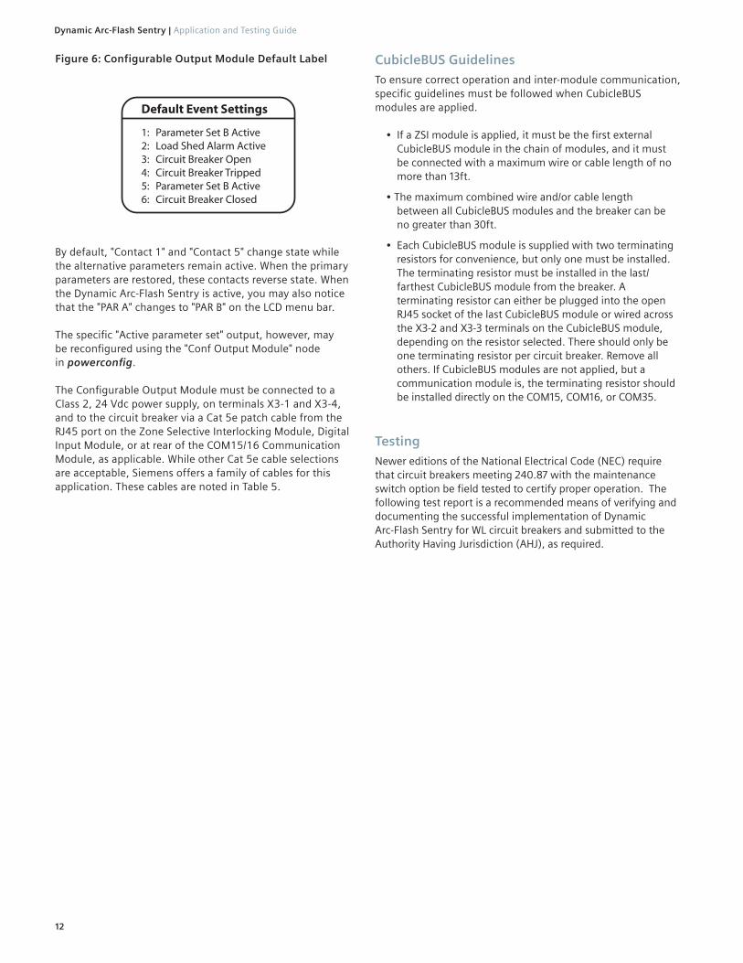
Default Event Settings
1: Parameter Set B Active2: Load Shed Alarm Active3: Circuit Breaker Open4: Circuit Breaker Tripped5: Parameter Set B Active6: Circuit Breaker Closed
Figure 6: Configurable Output Module Default Label
By default, "Contact 1" and "Contact 5" change state while the alternative parameters remain active. When the primary parameters are restored, these contacts reverse state. When the Dynamic Arc-Flash Sentry is active, you may also notice that the "PAR A" changes to "PAR B" on the LCD menu bar.
The specific "Active parameter set" output, however, may be reconfigured using the "Conf Output Module" node in powerconfig.
The Configurable Output Module must be connected to a Class 2, 24 Vdc power supply, on terminals X3-1 and X3-4, and to the circuit breaker via a Cat 5e patch cable from the RJ45 port on the Zone Selective Interlocking Module, Digital Input Module, or at rear of the COM15/16 Communication Module, as applicable. While other Cat 5e cable selections are acceptable, Siemens offers a family of cables for this application. These cables are noted in Table 5.
CubicleBUS GuidelinesTo ensure correct operation and inter-module communication, specific guidelines must be followed when CubicleBUS modules are applied.
• If a ZSI module is applied, it must be the first external CubicleBUS module in the chain of modules, and it must be connected with a maximum wire or cable length of no more than 13ft.
• The maximum combined wire and/or cable length between all CubicleBUS modules and the breaker can be no greater than 30ft.
• Each CubicleBUS module is supplied with two terminating resistors for convenience, but only one must be installed. The terminating resistor must be installed in the last/ farthest CubicleBUS module from the breaker. A terminating resistor can either be plugged into the open RJ45 socket of the last CubicleBUS module or wired across the X3-2 and X3-3 terminals on the CubicleBUS module, depending on the resistor selected. There should only be one terminating resistor per circuit breaker. Remove all others. If CubicleBUS modules are not applied, but a communication module is, the terminating resistor should be installed directly on the COM15, COM16, or COM35.
TestingNewer editions of the National Electrical Code (NEC) require that circuit breakers meeting 240.87 with the maintenance switch option be field tested to certify proper operation. The following test report is a recommended means of verifying and documenting the successful implementation of Dynamic Arc-Flash Sentry for WL circuit breakers and submitted to the Authority Having Jurisdiction (AHJ), as required.

Siemens Industry, Inc.
All steps confirmed and passed Tested By: Date:
Siemens Order No. CBWP-DASWP-0420
Siemens Type WL Dynamic Arc-Flash Sentry Test Report
Nameplate Data
Customer: Circuit Breaker:
Substation: Catalog No.: Serial No.:
Trip Unit Settings: DAS Inactive (Parameter Set A)
Pickup Setting (A) Time Delay (ms)
Long Time
Short Time
Instantaneous
Ground Fault
GF Mode Direct Sum
Trip Unit Settings: DAS Active (Parameter Set B)
Pickup Setting (A) Time Delay (ms)
Long Time
Short Time
Instantaneous
Ground Fault
GF Mode Direct Sum
Procedure
1. Verify Dynamic Arc-Flash Sentry (DAS) is INACTIVE
DAS activation switch is “OFF”
“Parameter Set A” observed on the trip unit display
Local status indicators (i.e. blue lamp) are “OFF”
2. Activate Dynamic Arc-Flash Sentry (DAS)
DAS activation switch is “ON”
“Parameter Set B” observed on the trip unit display
Local status indicators (i.e. blue lamp) are “ON”
3. De-activate Dynamic Arc-Flash Sentry (DAS)
DAS activation switch is “OFF”
“Parameter Set A” observed on the trip unit display
Local status indicators (i.e. blue lamp) are “OFF”

Remote DAS Activation The Dynamic Arc-Flash Sentry application is activated remotely, either by a manual operation, or by an automatic/automated activation system.
In order to remotely or automatically activate the DAS application, an input solution is necessary. Some typical input devices are:
• Key operated switch • Padlockable switch • Light curtain • Door switch • Motion detector • Laser sentry • Remote mounted control switchboard (HMI control panel)
The MMB300 and the remote activation switch must be wired in accordance with Figure 8. The normal operating mode is activated by a normally closed (NC) contact wired to the MMB300. When that normally closed contact opens, the Dynamic Arc-Flash Sentry mode is activated.
Figure 8: 3VA6 with MMB300 Basic Wiring Diagram
The status of the Dynamic Arc-Flash Sentry system is displayed on the 3VA6 ETU display (see Figure 8).
Figure 9: 3VA6 ETU Display
Remote DAS Indication One of the most common means of indicating that the DAS is active is to illuminate a blue indicating lamp(s) or light column(s) located near the approach area, so that the current operating mode is clearly visible to the operators prior to entering the arc-flash boundary. Connection information for the indicating lamp is shown in Figure 8.
14
Dynamic Arc-Flash Sentry | Application and Testing Guide
3VA6 Molded-Case Circuit BreakersThe Dynamic Arc-Flash Sentry functionality requires the Siemens MMB300 Maintenance Mode Box trip unit accessory, which includes the Dynamic Arc-Flash Sentry functionality.
If the MMB300 was not supplied with the original 3VA6 circuit breaker, it may be retrofit into an existing 3VA6 circuit breaker application.
In addition, a Class 2, 24Vdc power supply (Listed in accordance with UL 1310) is needed to power the trip unit and the MMB300 accessory. For your convenience, Siemens recommends two models of Class 2 power supplies, converting 120 Vac control power to Class 2 regulated, 24 Vdc. These power supplies are noted in Table 2. Other Class 2 power supplies are available.
The recommended power supplies, as well as the MMB300 modules, are designed to be installed on 35mm DIN rail.
When the Dynamic Arc-Flash Sentry mode is activated, the Instantaneous pickup setting (Ii) is reduced to the Dynamic Arc Flash level. The factory setting for DAS Ii is shown in Figure 7. The default setting may be altered using powerconfig.
Likewise, if the trip unit is equipped with ground fault protection, the ground fault pickup setting (Ig) is reduced to the Dynamic Arc Flash level. The factory setting for DAS Ig is shown in Figure 7. The default setting may be altered using powerconfig.
Figure 7: 3VA6 DAS Protection Parameters
All molded case circuit breakers with electronic trip units (ETUs 3-series, 5-series and 8-series) receive the signal for switchover of the protection parameters to DAS mode via the MMB300 maintenance mode box applied with the appropriate control scheme.
Additionally, it is possible to activate DAS mode for the ETUs 5-series and 8-series directly at the molded case circuit breakers via the keys on the LCD display.
The default settings for Ii or Ig may be altered to higher pickup values utilizing a software tool called ‘powerconfig’. Powerconfig is designed to program Siemens type 3VA6 circuit breakers and the associated trip unit accessories. It runs on Windows-based computers and may be downloaded free of charge at the following location:
https://support.industry.siemens.com/cs/products?mfn=ps&pnid=19790&lc=en-WW
3VA molded case circuit breakers with UL and IEC certification
82 Manual, 01/2019, L1V30435333-01

. 15
Application and Testing Guide | Dynamic Arc-Flash Sentry
Steady illumination Flashing Off
The MMB300 also provides local indication when the DAS mode is active. See Figure 10 for definition of the MMB300 indicators.
Figure 10: MMB300 Display
TestingNewer editions of the National Electrical Code (NEC) require that circuit breakers meeting 240.87 with the maintenance switch option be field tested to certify proper operation. The following test report is a recommended means of verifying and documenting the successful implementation of Dynamic Arc-Flash Sentry for 3VA6 circuit breakers and submitted to the Authority Having Jurisdiction (AHJ), as required.

Siemens Industry, Inc.
All steps confirmed and passed Tested By: Date:
Siemens Order No. CBWP-DASWP-0420
Siemens Type 3VA6 Dynamic Arc-Flash Sentry Test Report
Nameplate Data
Customer: Circuit Breaker:
Substation: Catalog No.: Serial No.:
Trip Unit Settings: DAS Inactive
Pickup Setting (A) Time Delay (ms)
Long Time
Short Time
Instantaneous
Ground Fault
GF Mode Direct Sum
Trip Unit Settings: DAS Active
Pickup Setting (A) Time Delay (ms)
Long Time
Short Time
Instantaneous
Ground Fault
GF Mode Direct Sum
Procedure
1. Verify Dynamic Arc-Flash Sentry (DAS) is wired correctly
Verify external power supplies are connected and energized
Verify DAS Mode is “active” in the ETU menu
Verify correct wiring of external annunciation power supply
Verify correct wiring of the DAS activation switch
Verify correct wiring of the external DAS local status indicator lamp
2. Activate Dynamic Arc-Flash Sentry (DAS)
Close the external DAS activation switch
Verify that the “ACT” LED is illuminated on the MMB300
Verify that the external DAS local status indicator lamp is illuminated
3. De-activate Dynamic Arc-Flash Sentry (DAS)
Open the DAS activation switch
Verify that the “ACT” LED is off on the MMB300
Verify that the external DAS local status indicator lamp is off

. 17
Application and Testing Guide | Dynamic Arc-Flash Sentry
VL Molded-Case Circuit Breakers The Sm@rtDAS option for the VL ETU 586 trip units incorporates a factory configured PLC/Communications Module solution with factory pre-configured software.
Remote DAS Activation The Dynamic Arc-Flash Sentry application is activated remotely, either by a manual operation, or by an automatic/automated activation system.
In order to remotely or automatically activate the DAS application, an input solution is necessary. Some typical input devices are:
• Key operated switch• Padlockable switch• Light curtain• Door switch• Motion detector• Laser sentry• Remote mounted control switchboard (HMI controlpanel)
Remote DAS Indication One of the most common means of indicating that the DAS is active is to illuminate a blue indicating lamp(s) or light column(s) located near the approach area, so that the current operating mode is clearly visible to the operators prior to entering the arc-flash boundary. The indicating lamp will only illuminate when the trip unit has confirmed that the Dynamic Arc-Flash settings have been activated via the communications module.
Commissioning -VL Sm@rt DASProper operation of the Dynamic Arc-Flash Sentry implemen-tation can be verified through the following process:
1. Review the equipment’s electrical drawings to identify the location of Sm@rtDAS activation switches or interface screen (HMI).
2. The electrical view on the HMI panel will show the circuit breakers with Sm@rtDAS highlighted.
3. After selecting a VL circuit breakera. Go to the trip unit graphic, scroll and select
"View parameter screen"b. Select "View protection" and then c. Scroll through and review the instantaneous
pickup (Ii) setting If unchanged from the factory, it will be set to the minimum pickup setting. Depending on the status of equipment commissioning, it may be elevated to the coordination setting.
4. Turn the DAS switch "on" for the subject VL circuit breaker. The blue Dynamic Arc-Flash Sentry indicator lamp will illuminate.
a. Refresh the instantaneous pickup setting by scrolling up or down on the keypad
b. Scroll back to review the instantaneous settings.
The default setting for Ii is [1.25x] the circuit breaker’s frame rating (Ir), however it may be elevated to a value recommended by the arc-flash coordination study.
Likewise, the default settings for short time pickup is [1.25 x Ir], with a time delay of 100ms.
If the Dynamic Arc-Flash Sentry settings are changed, it is recommended to verify that the settings be verified by the steps 3 and 4 (above) to ensure they were accepted by the PLC.
TestingNewer editions of the National Electrical Code (NEC) require that circuit breakers meeting 240.87 with the maintenance switch option be field tested to certify proper operation. The following test report is a recommended means of verifying and documenting the successful implementation of Dynamic Arc-Flash Sentry for VL circuit breakers and submitted to the Authority Having Jurisdiction (AHJ), as required.

Siemens Industry, Inc.
All steps confirmed and passed Tested By: Date:
Siemens Order No. CBWP-DASWP-0420
Siemens Type VL Dynamic Arc-Flash Sentry Test Report
Nameplate Data
Customer: Circuit Breaker:
Substation: Catalog No.: Serial No.:
Trip Unit Settings: DAS Inactive
Pickup Setting (A) Time Delay (ms)
Long Time
Short Time
Instantaneous
Ground Fault
GF Mode Direct Sum
Trip Unit Settings: DAS Active
Pickup Setting (A) Time Delay (ms)
Long Time
Short Time
Instantaneous
Ground Fault
GF Mode Direct Sum
Procedure
1. Verify Dynamic Arc-Flash Sentry (DAS) is INACTIVE
DAS activation switch is “OFF”
Local status indicators (i.e. blue lamp) are “OFF”
2. Activate Dynamic Arc-Flash Sentry (DAS)
DAS activation switch is “ON”
Local status indicators (i.e. blue lamp) are “ON”
3. De-activate Dynamic Arc-Flash Sentry (DAS)
DAS activation switch is “OFF”
Local status indicators (i.e. blue lamp) are “OFF”

Sentron Sensitrip IV Molded-Case Circuit Breakers
The Dynamic Arc-Flash Sentry functionality only requires the Sensitrip IV electronic trip unit, which as a standard, includes the Dynamic Arc-Flash Sentry functionality.
An external 24Vdc, UL Class 2, power supply is required to implement this feature. On the right side of the circuit breaker are six multi-colored 2-foot length, 18 AWG wires for connection.
Table 8: Sensitrip IV Wire Lead Identification
Wire Color Function Rating
Red 24Vdc LINE24Vdc + 20% 20mA max.
Black 24Vdc COM
White INPUT+ 24Vdc 5mA typ. sinked
Brown INPUT - (24Vdc COM)
Yellow OUTPUT+ 24Vdc 100mA max sourced
Blue OUTPUT - (24Vdc COM)
When the distance between circuit breakers and devices exceed this two foot pigtail lead requirement, the additional interconnection wiring must be 12 – 18 AWG shielded, twisted-pair and < 1000-feet (300 meters). Refer to Figure 11 for an example Dynamic Arc-Flash Sentry wiring diagram. In this example, the recommended components listed can support up to 25 circuit breakers.
Figure 11: Example Maintenance Mode Wiring Diagram
When the Dynamic Arc-Flash Sentry mode is activated, the Instantaneous pickup setting (Ii) is reduced to the lessor of [2 x In] and the [Ii dial setting].
Dynamic Arc-Flash Sentry is enabled by configuring series of DIP switches under the trip unit cover. The default setting is set to Dynamic Arc-Flash Sentry "active." See Figure 12 for identifying where to find the DIP switches for this configuration step.
. 19
Application and Testing Guide | Dynamic Arc-Flash Sentry
Figure 12: Configuration Switch
DIP Switch ConfigurationOn the front of the Sensitrip IV trip unit there is a 4-position configuration switch for configuring the Dynamic Arc-Flash Sentry, ZSI Mode and Ground Fault Method. Use a small pocket screwdriver to open the access cover. The shipping default of this DIP switch is with all positions in the DOWN position.
Switch #1:DOWN = Selects Dynamic Arc-Flash Sentry (Maintenance Mode)UP = Selects Zone Selective Interlocking Mode
Switch #2:DOWN = Disables Short Time Zone InterlockingUP = Enables Short Time Zone Interlocking
Switch #3:DOWN = Disables Ground Fault Zone InterlockingUP = Enables Ground Fault Zone Interlocking
Switch #4:DOWN = Selects Ground Fault Residual MethodUP = Selects Ground Fault Ground Return Method
Remote DAS Activation The Dynamic Arc-Flash Sentry application is activated remotely, either by a manual operation, or by an automatic/automated activation system.
In order to remotely or automatically activate the DAS application, an input solution is necessary. Some typical input devices are:
• Key operated switch• Padlockable switch• Light curtain• Door switch• Motion detector• Laser sentry• Remote mounted control switchboard (HMI control panel)
The remote activation switch must be wired in accordance with Figure 11. The normal operating mode is activated by a normally open (NO) contact wired to the Sensitrip IV Electronic Trip Unit (ETU). When that normally open contact closes, the Dynamic Arc-Flash Sentry mode is activated.
The status of the Dynamic Arc-Flash Sentry system is displayed on the Sensitrip IV ETU display (see Figure 13).
UP
DOWN
Test Connector Status Indicators

Figure 13: Status Indicators and Test Connector
Remote DAS Indication One of the most common means of indicating that the DAS is active is to illuminate a blue indicating lamp(s) or light column(s) located near the approach area, so that the current operating mode is clearly visible to the operators prior to entering the arc-flash boundary. Connection information for the indicating lamp is shown in Figure 11.
The Sensitrip IV trip unit also provides local indication when the DAS mode is active. See Table 9 for definition of the LED indicators.
Table 9: Sensitrip IV LED Indicators
LED State Trip Unit State
Active
OFF Ok. Ipri < min Ipri to power trip unit.
Flashing GREEN (1Hz) Ok. Trip unit fully operational.
Flashing GREEN (>>1Hz) Ok. Ipri < min Ipri to power trip unit.
Static REDTrip unit in error state. Contact technical support
Overload
OFF Ok
Flashing AMBER Trip pending Ipri > Ir
Static AMBER Trip pending Ipri > Ir* 115%
Maint. Mode
OFF Maint. Mode OFF
Static BLUE Maint. Mode ON
TestingNewer editions of the National Electrical Code (NEC) require that circuit breakers meeting 240.87 with the maintenance switch option be field tested to certify proper operation. The following test report is a recommended means of verifying and documenting the successful implementation of Dynamic Arc-Flash Sentry for Sentron Sensitrip IV circuit breakers and submitted to the Authority Having Jurisdiction (AHJ), as required.
20
Dynamic Arc-Flash Sentry | Application and Testing Guide
UP
DOWN
Test Connector Status Indicators

Siemens Industry, Inc.
All steps confirmed and passed Tested By: Date:
Siemens Order No. CBWP-DASWP-0420
Siemens Type Sensitrip IV Dynamic Arc-Flash Sentry Test Report
Nameplate Data
Customer: Circuit Breaker:
Substation: Catalog No.: Serial No.:
Trip Unit Settings: DAS Inactive
Pickup Setting (A) Time Delay (ms)
Long Time
Short Time
Instantaneous
Ground Fault
GF Mode Direct Sum
Trip Unit Settings: DAS Active
Pickup Setting (A) Time Delay (ms)
Long Time
Short Time
Instantaneous
Ground Fault
GF Mode Direct Sum
Procedure
1. Verify Dynamic Arc-Flash Sentry (DAS) is wired correctly
Verify external power supplies are connected and energized
Verify DIP switches are correctly positioned for Dynamic Arc-Flash Sentry
Verify correct wiring of the DAS activation switch
Verify correct wiring of the external DAS status indicator lamp
2. Activate Dynamic Arc-Flash Sentry (DAS)
Close the external DAS activation switch
Verify that the local status indicators (blue LED on the circuit breaker and the external signal lamp) are both illuminated
3. De-activate Dynamic Arc-Flash Sentry (DAS)
Open the external Maintenance Mode switch
Verify that the local status indicators (blue LED on the circuit breaker and the external signal lamp) are both off

22
Dynamic Arc-Flash Sentry | Application and Testing Guide
Notes:

. 23
Application and Testing Guide | Dynamic Arc-Flash Sentry
Notes:

Published by Siemens 2020
Siemens Industry, Inc. 5400 Triangle Parkway Norcross, GA 30092
Siemens Technical Support: 1-800-333-7421 [email protected]
Subject to change without prior notice All rights reserved Order No. CBWP-DASWP-0720 Printed in USA-CP © 2020 Siemens Industry, Inc.
This guide does not purport to cover all details or potential means of application, nor is it intended to provide instruction for installation, operation, or maintenance of the system.
Please reference the most recent edition of the associated WL Circuit Breaker Instruction Manual for these details.
The technical data presented in this document is based on an actual case or on as-designed parameters, and therefore should not be relied upon for any specific application and does not constitute a performance guarantee for any projects. Actual results are dependent on variable conditions. Accordingly, Siemens does not make representations, warranties, or assurances as to the accuracy, currency or completeness of the content contained herein. If requested, we will provide specific technical data or specifications with respect to any customer’s particular applications. Our company is constantly involved in engineering and development. For that reason, we reserve the right to modify, at any time, the technology and product specifications contained herein.