dynamic behaviour of a two-stage cycloidal speed reducer
TRANSCRIPT

Tehnički vjesnik 25, Suppl. 2(2018), 291-298 291
ISSN 1330-3651 (Print), ISSN 1848-6339 (Online) https://doi.org/10.17559/TV-20160530144431 Original scientific paper
Dynamic Behaviour of a Two-Stage Cycloidal Speed Reducer of a New Design Concept
Mirko BLAGOJEVIĆ, Miloš MATEJIĆ, Nenad KOSTIĆ
Abstract: Traditional cycloidal speed reducers (with two cycloid discs per one stage, mutually turned by an angle of 180°) are well known for their remarkable dynamic stability. This paper analyses dynamic behaviour of a two-stage cycloidal speed reducer of a new concept, in which only one cycloid disc is used for each stage in order to further enhance its compactness. Lagrange’s displacement equations have been used to develop independent dynamic models for both the first and the second stage (six degrees of displacement freedom for the first stage, and eight degrees of displacement freedom for the second stage). A normal force acting at the contact of the cycloid disc teeth and the corresponding ring gear roller has been taken as an excitation force. For the newly designed two-stage cycloidal speed reducer, systems of differential displacement equations of the first and second stage have been solved using the Matlab – Simulink software package. A comprehensive analysis of the obtained diagrams of elastic dynamic contact forces of the first and second stage has revealed a certain analogy. In terms of dynamics, the cycloid disc of the second stage behaves similarly to the cycloid disc of the first stage. Since these cycloid discs are mutually turned by an angle of 180°, it can be concluded that from the aspect of the cycloid disc load, the two-stage cycloidal speed reducer of a new design concept exhibits good dynamic balance and stability.
Keywords: cycloid speed reducer; cycloid disc; dynamic analysis; stiffness
1 INTRODUCTION
In analysis of dynamic behaviour of gear trains, external and internal dynamic loads should be differentiated based on the nature and origin of the load and angular velocities. The external dynamic loads include changes in torques, forces and angular velocities of the gears due to changes in the driving engine. The internal dynamic loads are the result of the mutual interaction of the meshing gears. Internal dynamic forces additionally load the gear elements and cause vibrations. These vibrations increase the excitation forces and thus increase the intensity of the total dynamic contact force. Therefore, the force is both the cause and the consequence of vibrations.
Dynamic behaviour of gear trains has been studied in great detail and reported in the literature. A whole range of different dynamic models of gear trains with external and internal gearing has been defined with the aim to closely describe their basic parameters [1, 2]. A lot of experimental studies have also been performed [3].
Cycloidal speed reducers belong to a new generation of mechanical gears. They are widely used in modern industry due to their good performances (reliable life-span, compact design, high efficiency, high gear ratio, etc) [4-7]. Geometric and kinematic properties of cycloidal speed reducers have been described thoroughly in the literature [8-15]. The stress-strain state of the elements of cycloidal speed reducers has also been analysed, as well as their efficiency [16, 17, 19].
Since dynamic balance is of great importance for reliable and stable operation of a cycloidal speed reducer, a number of papers dealing with this subject have been published in recent years. Thube and Bobak used modern software to make a series of dynamic simulations of a cycloidal speed reducer, which were then used to analyse contact forces and Von Mises stresses on its vital elements [20, 21]. Hsieh used the SolidWorks COSMOS software to analyse the velocity of the output shaft as a function of the rotational angle of the input shaft [22-24]. He also studied the stress on the cycloidal speed reducer elements as a function of the rotational angle of the input shaft.
a) b)Figure 1 A two-stage cycloidal speed reducer of a new design concept -
a) a 3D model, b) a photo of the manufactured cycloidal reducer [19]
A two-stage cycloidal speed reducer of a new design concept (Fig. 1) was developed and presented in the papers [19, 25]. While the cycloidal speed reducer of a traditional concept engages two cycloid discs mutually turned by an angle of 180° (in order to balance the dynamic forces) for each stage, the newly developed cycloidal speed reducer uses only one cycloid disc for each stage (with cycloid discs of both stages also mutually turned by 180°). This way the size of the cycloidal speed reducer is significantly decreased which has positive effects on its compactness.
It is very difficult if not impossible to define a dynamical model of a cycloidal speed reducer that will simulate its dynamic behaviour adequately. Traditionally designed cycloidal speed reducers (with two cycloid discs per stage) are well known for their dynamic stability. In this paper, the known dynamic models of involute gear trains with internal and external gearing [1-3] were used to develop a dynamic model of a two-stage cycloidal speed reducer of a new design concept [19]. In fact, separate dynamical models were developed for both stages and their dynamic stability was analysed by varying values of some parameters.
2 DYNAMIC MODEL OF THE CYCLOIDAL SPEED REDUCER – BASIC ASSUMPTIONS
Analysis of dynamic behaviour of a mechanical system is crucial for its design process. Nowadays, noise in

Mirko BLAGOJEVIĆ et al.: Dynamic Behaviour of a Two-Stage Cycloidal Speed Reducer of a New Design Concept
292 Technical Gazette 25, Suppl. 2(2018), 291-298
gear trains is one of the most important fields of study, especially when gear trains are used in automotive and navy industries.
Lagrange’s equations have been used for mathematical interpretation of dynamic behaviour of the cycloidal speed reducer. In a general case, they have the following form:
pk k
i i i i
d ,d
Ni
EE E Qt q q q q
Φ∂ ∂ ∂ ∂− = − − + ∂ ∂ ∂ ∂
(1)
where: Ek – kinetic energy, Ep – potential energy, Φ – dissipation function, qi – generalized coordinates, N
iQ –conservative forces.
In a matrix form, the differential displacement equation can be written as:
{ } { } { } { } ,+ + =M q B q C q Q (2)
where: М – mass matrix, B – damping matrix, C – stiffness matrix, {Q} – generalized forces vector, { q} – generalized acceleration vector, { q } – generalized velocity vector, {q} – generalized movement vector.
A change in the number of teeth pairs of the cycloid disc and the ring gear rollers that mesh simultaneously and transfer the load causes a change in the size of the total deformation at the contact w(t), in the stiffness per unit width of the cycloid disc tooth c(t) and in the normal excitation contact force Fn(t). The change in the contact excitation force in time is the major source of the forced cycloid disc vibrations whose basic frequency equals the excitation force frequency. The character of free vibrations caused by collisions of the cycloid disc teeth and the ring gear at their entry into meshing can be very different.
In this paper, it has been assumed [26-28] that the normal excitation contact force of the system Fn(t) changes proportionally to the change in deformation of the meshing teeth and that the stiffness equals the average constant stiffness c=const.
Thus, the excitation force Fn(t) is calculated based on the expression:
n ( ) ( ) ,F t c w t b= ⋅ ⋅ (3)
where: Fn(t) – excitation force, c – stiffness, w(t) – total deformation at the contact, b – cycloid disc width.
During the cycloidal speed reducer operation, the total force at the flanks of the meshing teeth of the cycloid disc and the ring gear rollers is the result of the force Fn(t) as well as the influence of the elastic dynamic contact force Fe:
e ,F c x k x= ⋅ + ⋅ (4)
where: x – total displacement at the contact of the cycloid disc teeth and the ring gear roller, x – corresponding velocity, k – damping coefficient at the contact of the cycloid disc teeth and the ring gear roller.
3 DYNAMIC MODEL OF THE FIRST STAGE
Fig. 2 shows the dynamic model of the first stage of the two-stage cycloidal speed reducer of a new design concept. The structure of the first stage is the same as the structure of the one-stage cycloidal speed reducer of a traditional design concept, the only difference being that instead of two only one cycloid disc is used. This system has six degrees of displacement freedom (three rotations and three translations).
The geometrical values from Fig. 2 are given in Tab. 1.
The elements of the first stage are connected in the following way: • The input shaft with the eccentric cam: elastic
connection of the stiffness c1 and the damper with the damping coefficient k1;
• Cycloid disc: elastic connection of the stiffness c2 andthe damper with the damping coefficient k2;
• Output roller: elastic connection of the stiffness c4 andthe damper with the damping coefficient k4.
The contacts between the elements of the cycloidal speed reducer are described in the following way: • Input shaft with an eccentric cam - cycloid disc:
elastic connection of the time-varying stiffness c1(t) and the damper with the damping coefficient k;
• Cycloid disc – stationary ring gear: elastic connection of the time-varying stiffness c2(t) and the damper with the damping coefficient k;
• Cycloid disc – output roller: elastic connection of thetime varying stiffness c3(t) and the damper with the damping coefficient k.
As already pointed out, the system excitation force Fn(t) acts at the contact of the cycloid disc teeth and the ring gear roller.
Figure 2 A dynamic model of the first stage
Fig. 2 shows that the total displacement x at the contact of the cycloid disc teeth and the ring gear roller is a connection between the cycloid disc rotation δ2 and its translation y2, and that it can be expressed as:
2 2 2x r yδ= + (5)
The kinetic energy of the first stage is:
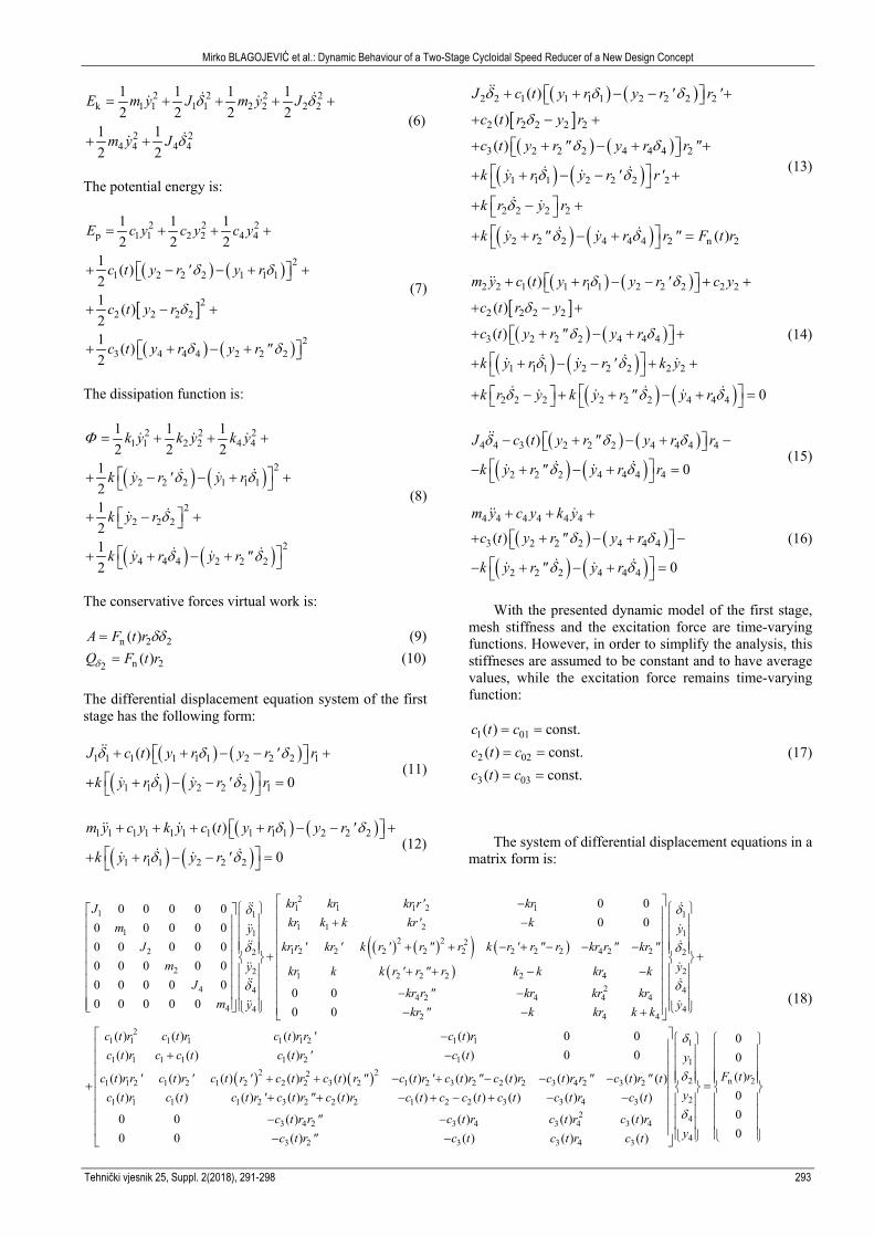
Mirko BLAGOJEVIĆ et al.: Dynamic Behaviour of a Two-Stage Cycloidal Speed Reducer of a New Design Concept
Tehnički vjesnik 25, Suppl. 2(2018), 291-298 293
2 2 2 2k 1 1 1 1 2 2 2 2
2 24 4 4 4
1 1 1 12 2 2 2
1 12 2
E m y J m y J
m y J
δ δ
δ
= + + + +
+ +
(6)
The potential energy is:
( ) ( )
[ ]
( ) ( )
2 2 2p 1 1 2 2 4 4
21 2 2 2 1 1 1
22 2 2 2
23 4 4 4 2 2 2
1 1 12 2 2
1 ( )21 ( )21 ( )2
E c y c y c y
c t y r ' y r
c t y r
c t y r y r "
δ δ
δ
δ δ
= + + +
+ − − + +
+ − +
+ + − +
(7)
The dissipation function is:
( ) ( )
( ) ( )
2 2 21 1 2 2 4 4
22 2 2 1 1 1
22 2 2
24 4 4 2 2 2
1 1 12 2 2
121212
k y k y k y
k y r ' y r
k y r
k y r y r "
Φ
δ δ
δ
δ δ
= + + +
+ − − + +
+ − +
+ + − +
(8)
The conservative forces virtual work is:
n 2 2( )A F t r δδ= (9)
n 22 ( )Q F t rδ = (10)
The differential displacement equation system of the first stage has the following form:
( ) ( )
( ) ( )1 1 1 1 1 1 2 2 2 1
1 1 1 2 2 2 1
( )
0
J c t y r y r ' r
k y r y r ' r
δ δ δ
δ δ
+ + − − + + + − − =
(11)
( ) ( )
( ) ( )1 1 1 1 1 1 1 1 1 1 2 2 2
1 1 1 2 2 2
( )
0
m y c y k y c t y r y r '
k y r y r '
δ δ
δ δ
+ + + + − − + + + − − =
(12)
( ) ( )[ ]( ) ( )
( ) ( )
( ) ( )
2 2 1 1 1 1 2 2 2 2
2 2 2 2 2
3 2 2 2 4 4 4 2
1 1 1 2 2 2 2
2 2 2 2
2 2 2 4 4 4 2 n 2
( )
( )
( )
( )
J c t y r y r ' r '
c t r y r
c t y r " y r r "
k y r y r ' r'
k r y r
k y r " y r r " F t r
δ δ δ
δ
δ δ
δ δ
δ
δ δ
+ + − − + + − +
+ + − + + + + − − + + − + + + − + =
(13)
( ) ( )[ ]( ) ( )
( ) ( )( ) ( )
2 2 1 1 1 1 2 2 2 2 2
2 2 2 2
3 2 2 2 4 4 4
1 1 1 2 2 2 2 2
2 2 2 2 2 2 4 4 4
( )
( )
( )
0
m y c t y r y r ' c y
c t r y
c t y r " y r
k y r y r ' k y
k r y k y r " y r
δ δ
δ
δ δ
δ δ
δ δ δ
+ + − − + + + − +
+ + − + + + + − − + +
+ − + + − + =
(14)
( ) ( )
( ) ( )4 4 3 2 2 2 4 4 4 4
2 2 2 4 4 4 4
( )
0
J c t y r " y r r
k y r " y r r
δ δ δ
δ δ
− + − + − − + − + =
(15)
( ) ( )
( ) ( )
4 4 4 4 4 4
3 2 2 2 4 4 4
2 2 2 4 4 4
( )
0
m y c y k y
c t y r " y r
k y r " y r
δ δ
δ δ
+ + +
+ + − + − − + − + =
(16)
With the presented dynamic model of the first stage, mesh stiffness and the excitation force are time-varying functions. However, in order to simplify the analysis, this stiffneses are assumed to be constant and to have average values, while the excitation force remains time-varying function:
1 01
2 02
3 03
( ) const. ( ) const. ( ) const.
c t cc t cc t c
= =
= =
= = (17)
The system of differential displacement equations in a matrix form is:
( ) ( )( ) ( )
21 1 1 2 11 11 1 21 1
2 2 21 2 2 2 2 2 2 2 2 4 2 22 2
2 2 1 24 4
4 4
0 00 0 0 0 00 00 0 0 0 0
0 0 0 0 00 0 0 0 00 0 0 0 00 0 0 0 0
kr kr kr r' krJkr k k kr' km y
kr r ' kr ' k r ' r " r k r ' r " r kr r " kr "Jm y kr k k r '
Jm y
δ
δ
δ
− + − + + − + − − − +
+
( )
1
1
2
22 2 2 42 4
4 2 4 4 44
2 4 4
21 1 1 1 1 1 2 1 1
1 1 1 1 1 2 1
1 1 2 1 2
0 00 0
( ) ( ) ( ) ( ) 0 0( ) ( ) ( ) ( ) 0 0
( ) ( )
y
yr " r k k kr k
kr r " kr kr krykr " k kr k k
c t r c t r c t r r ' c t rc t r c c t c t r ' c t
c t r r ' c t r ' c
δ
δ
δ
+ + − − − − − − +
−+ −
+
( ) ( )2 221 2 2 2 3 2 1 2 3 2 2 2 3 4 2 3 2
1 1 1 1 2 3 2 2 2 1 2 2 3 3 4 32
3 4 2 3 4 3 4 3 4
3 2 3
( ) ( ) ( ) ( ) ( ) ( ) ( ) ( ) ( )( ) ( ) ( ) ( ) ( ) ( ) ( ) ( ) ( ) ( )
0 0 ( ) ( ) ( ) ( )0 0 ( ) (
t r ' c t r c t r " c t r ' c t r " c t r c t r r " c t r " tc t r c t c t r ' c t r " c t r c t c c t c t c t r c t
c t r r " c t r c t r c t rc t r " c t
+ + − + − − −+ + − + − + − −
− −− −
1
1
2 n 2
2
4
43 4 3
00( )000) ( ) ( )
yF t r
y
yc t r c t
δ
δ
δ
=
(18)

Mirko BLAGOJEVIĆ et al.: Dynamic Behaviour of a Two-Stage Cycloidal Speed Reducer of a New Design Concept
4 DYNAMIC MODEL OF THE SECOND STAGE
The difference between the first and the second stage is that in the second stage the ring gear is not stationary; it revolves around its own axis. It further means that this system has eight degrees of displacement freedom (four rotations and four translations). In this case, the excitation force Fn(t) acts at the contact of the cycloid disc teeth and the ring gear roller. Fig. 3 shows the dynamic model of the second stage.
Figure 3 A dynamic model of the second stage
As seen in Fig. 3, the total displacement x at the contact of the cycloid disc teeth and the ring gear roller can be expressed as:
2 2 2 3 3 3x r y r yδ δ= − + − (19)
The kinetic energy of the second stage is:
2 2 2 2k 1 1 1 1 2 2 2 2
2 2 2 23 3 3 3 4 4 4 4
1 1 1 12 2 2 2
1 1 1 12 2 2 2
E m y J m y J
m y J m y J
δ δ
δ δ
= + + + +
+ + + +
(20)
The potential energy is:
( ) ( )
( ) ( )
( ) ( )
2 2 2 2p 1 1 2 2 3 3 4 4
21 2 2 2 1 1 1
22 2 2 2 3 3 3
23 2 2 2 4 4 4
1 1 1 12 2 2 2
1 ( )21 ( )21 ( )2
E c y c y c y c y
c t y r ' y r
c t y r y r
c t y r " y r
δ δ
δ δ
δ δ
= + + + +
+ − − + +
+ − − + +
+ + − +
(21)
The dissipation function is:
( ) ( )
( ) ( )
( ) ( )
2 2 2 21 1 2 2 3 3 4 4
22 2 2 1 1 1
22 2 2 3 3 3
22 2 2 4 4 4
1 1 1 12 2 2 2
121212
k y k y k y k y
k y r ' y r
k y r y r
k y r " y r
Φ
δ δ
δ δ
δ δ
= + + + +
+ − − + +
+ − − + +
+ + − +
(22)
The conservative forces virtual work is:
n 2 2 n 3 3( ) ( )A F t r F t rδ δδ δδ= + (23)
n 22 ( )Q F t rδ = (24)
n 33 ( )Q F t rδ = (25)
Making the same assumptions as with the dynamic model of the first stage, a matrix form the displacement equation system for the second stage can be written as:
21 1 1 2 1
1 11 1 21 1
2 1 22
2 2
3 3
3 3
4 4
4 4
0 0 0 00 0 0 0 0 0 0
0 0 0 00 0 0 0 0 0 00 0 0 0 0 0 00 0 0 0 0 0 00 0 0 0 0 0 00 0 0 0 0 0 00 0 0 0 0 0 00 0 0 0 0 0 0
kr kr kr r ' krJ
kr k k kr km yJ kr r
m yJ
m yJ
m y
δ
δ
δ
δ
− ′ + − +
( ) ( )( ) ( )( )
1
12 2 2
2 2 2 2 2 2 2 2 3 2 4 2 2
1 2 2 2 2 3 42
2 3 3 3 3
2 3 32
4 2 4 4 4
2 4 4
3
0 0 0 00 0 0 0
0 0 0 00 0 0 0
y' kr ' k r ' r " r k r ' r " r kr r kr kr r " kr "
kr k k r ' r " r k k kr k kr k
kr r kr kr krkr k kr k k
kr r " kr kr krkr " k kr k k
δ
δ
+ + − + − − − − − − + − + − − − −
− − + − −
− − +
( ) ( )
2
2
3
3
4
4
21 1 1 1 1 1 2 1 1
1 1 1 1 1 2 12 22
1 1 2 1 2 1 2 2 2 3 2 1 2 3 2 2 2 2 2 3 2
( ) ( ) ( ) ( ) 0 0 0 0( ) ( ) ( ) ( ) 0 0 0 0
( ) ( ) ( ) ( ) ( ) ( ) ( ) ( ) ( ) ( )
y
y
y
c t r c t r c t r r ' c t rc t r c t c c t r ' c t
c t r r ' c t r ' c t r ' c t r c t r " c t r ' c t r " c t r c t r r c t
δ
δ
+
−+ −
+ + − + −
+
2 3 4 2 3 2
1 1 1 1 2 3 2 2 2 1 2 3 2 2 3 2 3 4 32
2 2 3 2 3 2 3 2 3
2 2 2 2 3 2 3 3
3 2 4 3
( ) ( )( ) ( ) ( ) ( ) ( ) ( ) ( ) ( ) ( ) ( ) ( ) ( )
0 0 ( ) ( ) ( ) ( ) 0 00 0 ( ) ( ) ( ) ( ) 0 0
0 0 ( ) ( )
r c t r r " c t r "c t r c t c t r ' c t r " c t r c t c t c t c c t r c t c t r c t
c t r r c t r c t r c t rc t r c t c t r c t r c
c t r " r c t r
− −− − − + − + + + − − − −
−− +
− −
1
1
2 n 2
2
3 n 3
3
2 44 3 4 3 4
43 2 3 3 4 4 3
00( )0( )000 0 ( ) ( )00 0 ( ) ( ) 0 0 ( ) ( )
yF t r
yF t r
y
c t r c t ryc t r " c t c t r c c t
δ
δ
δ
δ
= − − +
(26)
294 Technical Gazette 25, Suppl. 2(2018), 291-298

Mirko BLAGOJEVIĆ et al.: Dynamic Behaviour of a Two-Stage Cycloidal Speed Reducer of a New Design Concept
Tehnički vjesnik 25, Suppl. 2(2018), 291-298 295
5 SOLUTION OF THE DISPLACEMENT EQUATIONS
This paper analyses dynamic behaviour of the two-stage cycloidal speed reducer of a new design concept with the following parameters: • Input power: P = 0.25 kW• Input number of rotations: n = 1390 min−1
• Teeth number of the cycloid disc of the first stage: z1 =11
• Teeth number of the cycloid disc of the second stage:z2 = 10
• Reduction ratio: u = 121• Cycloid disc width: b = 13.3 mm.
Calculation of the total deformation at the contact point of the cycloid disc teeth and the corresponding ring gear roller w(t) is made based on Prof. Lixing’s recommendations [29].
Table 1 Masses, inertia moments and dimensions of the cycloidal speed reducer elements
Quantity Value Mass of the input shaft with an eccentric cam m1 = 0.17 kg Mass of the cycloid disc (cycloid discs of the first and second stage can be considered to have equal masses due to their almost equal
dimensions)
m2 = 0.74 kg
Mass of the ring gear of the second stage m3 = 4.2 kg Mass of the output roller together with the
output disc m4 = 0.7 kg
Inertia moment of the input shaft with an eccentric cam
J1 = 26 kgmm2
Inertia moment of the cycloid disc J2 = 1422.3 kgmm2
Inertia moment of the ring gear of the second stage
J3 = 10886.4 kgmm2
Inertia moment of the output roller together with the output disc
J4 = 762.5 kgmm2
External radius of the eccentric cam r1 = 17.5 mm Radius of the central opening of the cycloid
disc 2 20mmr ′ =
Radius of the circle with output rollers 2 39mmr ′′ =
Radius of the ring gear pitch circle r3 = 72 mm Radius of the cycloid disc circle with openings
for output rollers r4 = 39 mm
Radius of the cycloid disc pitch circle of the first stage
r2 = 62 mm
Radius of the cycloid disc pitch circle (of the first and second stage)
r2 = 62 mm
Table 2 Adopted values of the stiffness and damping coefficients Quantity Value
K 5000 Ns/m k1 2500 Ns/m k2 200 Ns/m k3 2000 Ns/m k4 1000 Ns/m c1(t) = c01 1.3×10⁸N/m c2(t) = c02 1.5×10⁷ N/m c3(t) = c03 1.5×10⁸N/m c1 2×10⁹ N/m c2 1.6×10⁸ N/m c3 2×10⁹ N/m c4 1.6×10⁸ N/m
Systems of differential displacement equations of the first and second stage of the two-stage cycloidal speed reducer are solved in the Matlab - Simulink program package by an iterative procedure, assuming that, in the first iteration, the cycloid disc tooth is exposed only to the action of the force Fn(t). Masses and inertia moments of the cycloidal speed reducer elements are given in Tab. 1.
The values of the stiffness and damping coefficients were adopted as given in Tab. 2, [26-28].
6 RESULTS AND DISCUSSION
In a theoretical case, half of the cycloid disc teeth take part in the load transfer so the specific load per one cycloid disc tooth is significantly less than in conventional cycloidal reducers with involute gears.This is considered as one of the greatest advantages of the cycloidal speed reducer. However, in practice, due to the clearances between the cycloid disc teeth and the ring gear rollers, the number of cycloid disc teeth in simultaneous contact is slightly smaller.
In this paper it has been assumed that two cycloid disc teeth simultaneously take part in the load transfer.
As part of this study, different values of stiffness and damping coefficients were used to make numerous simulations of the cycloidal speed reducer dynamic behaviour in the Matlab – Simulink software. Some of the results are presented here.
Solutions of the displacement differential equations of the first and second stage of the two-stage cycloidal speed reducer of a new design concept (equations 18 and 26) obtained in the Matlab – Simulink software for the recommended values of the stiffness and damping coefficients (Tab. 2) are given in Fig. 4 (the first stage) and Fig. 5 (the second stage).
Having carefully analysed the obtained results (Figs. 4a and 5a) it can be concluded that the maximum values of the normal excitation contact forces Fn(t) on cycloid discs of the first and second stage are very similar (Fn1(t) =1848 N, Fn2(t) =2068.7 N) and that their diagrams are alike.
Furthermore, analysis of the diagrams of elastic dynamic contact forces (Figs. 4d and 5d) has pointed out two components. The first one comes from the normal excitation contact force Fn(t) while the second one is the result of the system’s own oscillations. The latter component is particularly prominent at the beginning of the meshing of the cycloid disc and the ring gear rollers. Later, the system’s own vibrations decrease but they do not cease completely.
Comparison of the diagrams of elastic dynamic contact forces (Figs. 4d and 5d) reveals certain analogy, namely, the dynamic behaviour of the cycloid disc of the second stage is very similar to the behaviour of the cycloid disc of the first stage (except for the fact that own vibrations are slightly more prominent in the first stage). From the aspect of the cycloid disc load and taking into consideration that these cycloid discs are mutually turned by an angle of 180°, it can be concluded that the cycloidal speed reducer is dynamically well balanced and stable.

Mirko BLAGOJEVIĆ et al.: Dynamic Behaviour of a Two-Stage Cycloidal Speed Reducer of a New Design Concept
296 Technical Gazette 25, Suppl. 2(2018), 291-298
a)
b)
c)
d)Figure 4 Solutions of differential displacement equations of the first stage;
a) Diagram of the normal excitation force; b) Diagram of the displacement; c) Diagram of the velocity; d) Diagram of the elastic dynamic contact force
Numerous simulations and detailed analyses have shown that stiffness values of the supports of the input shaft with the eccentric cam (c1), cycloid disc (c2), ring gear (c3) and output roller (c4), as well as the corresponding damping coefficient values have no significant effect on the layout of the diagram of the elastic dynamic contact force. The same can be said for the mesh stiffness of the input shaft and the eccentric cam with the cycloid disc (c01) and the mesh stiffness of the cycloid disc with the output shaft (c03).
The mesh stiffness of the cycloid disc and the ring gear (c02) has the greatest effect on the elastic dynamic contact force as well as on the resulting displacement and velocity.
The influence of the stiffness c02 on the diagram of the elastic dynamic contact force for the first stage is shown in Fig. 6. For the second stage, the situation is very similar.
a)
b)
c)
d)Figure 5 Solutions of differential displacement equations of the second
stage; a) Diagram of the normal excitation contact force; b) Diagram of the displacement; c) Diagram of the velocity; d) Diagram of the elastic dynamic
contact force
Figure 6 The influence of the stiffness c02 on the elastic dynamic contact force (for the first stage)

Mirko BLAGOJEVIĆ et al.: Dynamic Behaviour of a Two-Stage Cycloidal Speed Reducer of a New Design Concept
Tehnički vjesnik 25, Suppl. 2(2018), 291-298 297
If for the stiffness c02, the recommended value of c02 = 1.5×10⁷ N/m is adopted, the diagram of the elastic dynamic contact force quickly becomes almost identical to the diagram of the normal excitation force. The similar will happen if the c02 = 1.2×10⁷ N/m is adopted, with small improvements in vibrations lowering at the beginning. When the stiffness values are above the recommended range, the diagram of the elastic dynamic contact force differs significantly from the diagram of the excitation force and the influence of own vibrations is much more prominent.
7 CONCLUSIONS
This paper analyses dynamic behaviour of the two-stage cycloidal speed reducer of a new design concept, in which only one cycloid disc is used for each stage. Based on the known dynamic models of train gears with external and internal gearing, independent dynamic models of the first and second stage have been developed in this paper. The differential displacement equations of the two-stage cycloidal speed reducer of a new design concept have been solved using the Matlab-Simulink software, which enabled the analysis of the influence of certain parameters on dynamic behaviour of the cycloidal speed reducer.
Investigations conducted in this paper have unambiguously shown that the mesh stiffness of the cycloid disc and the stationary ring gear c02 has the greatest influence on the output results. If the values of c02 are above the recommended range it has a big impact on vibrations, while in opposite case a small improvements are noticeable.
When the adopted parameter values of the differential displacement equations are within the recommended range, it can be said with great certainty that the presented two-stage cycloidal speed reducer has good dynamic properties and that the new, much more compact design does not affect the dynamic balance exhibited by the old concept model.
The values of elastic dynamic contact forces obtained for different loads are valuable input parameters for analysis of the stress-strain status of vital elements of the two-stage cycloidal speed reducer, which will certainly be the subject of our further investigations.
Acknowledgements
This paper is a result of project TR33015.The project is financed from the Ministry of Education, Science and Technological Development of the Republic of Serbia. The project is titled "Investigation and development of Serbian zero-net energy house". We would like to thank the Ministry of Education, Science and Technological Development of the Republic of Serbia for their financial support during these investigations.
8 REFERENCES
[1] Li, S. & Kahraman, A. (2010). A Transient Mixed Elastohydrodynamic Lubrication Model for Spur Gear Pairs. Journal of Tribology, 132(1), 011501. https://doi.org/10.1115/1.4000270
[2] Kahraman, A., Ligata, H., & Singh, A. (2010). Influence of Ring Gear Rim Thickness on Planetary Gear Set Behavior. Journal of Mechanical Design, 132(2), 021002. https://doi.org/10.1115/1.4000699
[3] Inalpolat, M. & Kahraman, A. (2009). A Theoretical and Experimental Investigation of Modulation Sidebands of Planetary Gear Sets. Journal of Sound and Vibrations, 323(3-5), 677-696. https://doi.org/10.1016/j.jsv.2009.01.004
[4] Kudrijavcev, V. N. (1966). Planetary Gear Train (in Russian). Mechanical Engineering, Leningrad.
[5] Lehmann, M. (1976). Calculation and Measurement of Forces Acting on Cycloid Speed Reducer (in German). PhD Thesis, Technical University Munich, Germany.
[6] Malhotra, S. K. & Parameswaran M. A. (1983). Analysis of a Cycloid Speed Reducer. Mechanism and Machine Theory, 18(6), 491-499. https://doi.org/10.1016/0094-114X(83)90066-6
[7] Gu, I. (1998). Design of Antibacklash Pin-Gearing. Journal of Mechanical Design, 120, 133-138.
https://doi.org/10.1115/1.2826665 [8] Blanche, J. G. & Yang, D. C. H. (1989). Cycloid Drives with
Machining Tolerances. Journal of Mechanisms, Transmissions, and Automation in Design, 111, 337-344. https://doi.org/10.1115/1.3259004
[9] Yang, D. C. H. & Blanche, J. G. (1990). Design and Application Guidelines for Cycloid Drives with Machining Tolerances. Mechanism and Machine Theory, 25(5), 487-501. https://doi.org/10.1016/0094-114X(90)90064-Q
[10] Litvin, F. & Feng P. (1996). Computerized Design and Generation of Cycloidal Gearings. Mechanism and Machine Theory, 31(7), 891-911. https://doi.org/10.1016/0094-114X(95)00115-F
[11] Chen, B., Zhong, H., Liu, J., Li, C., & Fang, T. (2012) Generation and Investigation of a New Cycloid drive with Double Contact. Mechanism and Machine Theory, 49, 270-283. https://doi.org/10.1016/j.mechmachtheory.2011.10.001
[12] Hwang, Y. W. & Hsieh, C. F. (2007) Geometric Design Using Hypotrochoid and Nonundercutting Conditions for an Internal Cycloidal Gear. Journal of Mechanical Design, 129, 413-420. https://doi.org/10.1115/1.2437806
[13] Yunhong, M., Changlin, W., & Liping, L. (2007). Mathematical Modeling of the Transmission Performance of 2K-H Pin Cycloid Planetary Mechanism. Mechanism and Machine Theory, 42(7), 776-790. https://doi.org/10.1016/j.mechmachtheory.2006.07.003
[14] Sensinger, J. (2010). Unified Approach to Cycloid Drive Profile, Stress, and Efficiency Optimization. Journal of Mechanical Design, 132, 024503. https://doi.org/10.1115/1.4000832
[15] Lin, W. S., Shin, Y. P., & Lee, J. J. (2014). Design of a Two-Stage Cycloidal Gear Reducer with Tooth Modifications. Mechanism and Machine Theory, 79, 184-197. https://doi.org/10.1016/j.mechmachtheory.2014.04.009
[16] Li, X., He, W., Li, L., & Schmidt, L. C. (2004). A New Cycloid Drive with High-Load Capacity and High Efficiency. Journal of Mechanical Design, 126(4), 683-686. https://doi.org/10.1115/1.1758254
[17] Gorla, C., Davoli, P., Rosa, F., Longoni, C., Chiozzi, F., & Samarani, A. (2008). Theoretical and Experimental Analysis of a Cycloidal Speed Reducer. Journal of Mechanical Design, 130(11), 112604. https://doi.org/10.1115/1.2978342
[18] Li, S. (2014). Design and Strenght Analysis Methods of the Trochoidal Gear Reducers. Mechanism and Machine Theory, 81, 140-154. https://doi.org/10.1016/j.mechmachtheory.2014.07.001
[19] Blagojevic, M., Marjanovic, N., Djordjevic, Z., Stojanovic, B., & Disic, A. (2011). A New Design of a Two-Stage Cycloidal Speed Reducer. Journal of Mechanical Design, 133(8), 085001. https://doi.org/10.1115/1.4004540
[20] Thube, S. & Bobak, T. (2011). The Dynamic Simulation and Analysis of a Cycloidal Speed Reducer. Proceeding of the

Mirko BLAGOJEVIĆ et al.: Dynamic Behaviour of a Two-Stage Cycloidal Speed Reducer of a New Design Concept
298 Technical Gazette 25, Suppl. 2(2018), 291-298
11th ASME International Power Transmission and Gearing Conference DETC2011, August 28-31, Washington, DC, USA. https://doi.org/10.1115/DETC2011-48494
[21] Thube, S. & Bobak, T. (2013). Dynamic Analysis of a Cycloidal Gearbox Using Finite Element Method. Gearsolutions, 35-44.
[22] Hsieh, C. F. (2014). Dynamics Analysis of Cycloidal Speed Reducers with Pinwheel and Nonpinwheel Designs. Journal of Mechanical Design, 136 (9), 091008. https://doi.org/10.1115/1.4027850
[23] Hsieh, C. F. (2014). The Effect on Dynamics of Using a New Transmission Design for Eccentric Speed Reducer. Mechanism and Machine Theory, 80, 1-16. https://doi.org/10.1016/j.mechmachtheory.2014.04.020
[24] Hsieh, C. F. (2015). Traditional Versus Improved Designs for Cycloidal Speed Reducers with a Small Tooth Difference: The Effect on Dynamics. Mechanism and Machine Theory, 86, 15-35. https://doi.org/10.1016/j.mechmachtheory.2014.11.013
[25] Blagojevic, M., Marjanovic, N., Djordjevic, Z., Stojanovic, B., Marjanovic, V., Vujanac, R., & Disic, A. (2014). Numerical and Experimental Analysis of the Cycloid Disc Stress State. Technical Gazette, 21(2), 377-382.
[26] Ognjanovic, M. & Agemi, F. (2010). Gear Vibrations in Supercritical Mesh-Frequency Range Caused by Teeth Impact. Journal of Mechanical Engineering, 56(10), 653-662.
[27] Batinic, V. (2001). Modal Analysis of Planetary Gear Trains. Journal of Mechanical Engineering Design, 4(1), 17-24.
[28] Blagojević, M., Nikolić, V., Marjanović, N., & Veljović, Lj., (2009). Analysis of Cycloid Drive Dynamic Behavior. Scientific Technical Review, 59(1), 52-56.
[29] Lixing, L., Xin, L., Weidong, H., & Yuanmei, Q. (1997). Accurate Force Analysis on Cycloid Drive. Proceeding of the 11th ASME International Power Transmission and Gearing Conference DETC2011, August 28-31, Washington, DC, USA.
Contact information:
Mirko BLAGOJEVIĆ, PhD, Associate professor (Corresponding author) University of Kragujevac, Faculty of Engineering Sestre Janjić 6, 34000 Kragujevac, Serbia [email protected]
Miloš MATEJIĆ, MSc, Teaching assistant University of Kragujevac, Faculty of Engineering Sestre Janjić 6, 34000 Kragujevac, Serbia [email protected]
Nenad KOSTIĆ, PhD, Research assistant University of Kragujevac, Faculty of Engineering Sestre Janjić 6, 34000 Kragujevac, Serbia [email protected]