dynamic properties for modeling and simulation of
TRANSCRIPT

DYNAMIC PROPERTIES FOR MODELING AND SIMULATION OFMACHINING: EFFECT OF PEARLITE TO AUSTENITE PHASETRANSITION ON FLOW STRESS IN AISI 1075 STEEL
Timothy J. Burns1, Steven P. Mates1, Richard L. Rhorer1, Eric P. Whitenton1,and Debasis Basak21National Institute of Standards and Technology, Gaithersburg, MD, USA2Orbital Sciences Corporation, Dulles, VA, USA
& The Pulse-Heated Kolsky Bar Laboratory at the National Institute of Standards and Technology(NIST) has been developed for the measurement of dynamic properties of metals. With this system, asmall sample can be pre-heated from room temperature to several hundred degrees C in less than asecond, prior to rapid loading in compression at strain rates up to the order of 104 per second. Amajor focus of this research program has been on investigating the influence of the heating rateand time at temperature on the flow stress of carbon steels, for application to the modeling and simu-lation of high-speed machining operations. The unique pulse heating capability of the NIST Kolskybar system enables flow stress measurements to be obtained under conditions that differ significantlyfrom those in which the test specimens have been pre-heated to a high temperature more slowly,because there is less time for thermally activated microstructural processes such as dislocationannealing, grain growth, and solid state phase transformations to take place. New experimentalresults are presented on AISI 1075 pearlitic steel samples that were pulse-heated up to and beyondthe austenite formation temperature of the material (723 �C). The data show that the flow stressdecreased by about 50% due to a phase transformation in the microstructure of the material fromthe stronger pearlitic phase to the weaker austenitic phase. As a result, the constitutive response beha-vior of the material cannot be modeled by a fixed-parameter constitutive model, like the Johnson-Cookflow stress model that is widely used in computer simulations of high-speed machining processes.
Keywords AISI 1075 steel, high-speed machining, Johnson-Cook model, split-Hopkinson pressure bar
INTRODUCTION
Prediction of the best machining parameters for a particular processand work material continues to be a challenge in manufacturing. The
This article is not subject to US copyright law.Address correspondence to T. J. Burns, NIST, 100 Bureau Drive, Mail Stop 8910, Gaithersburg,
Maryland 20899-8910, USA. E-mail: [email protected]
Machining Science and Technology, 15:1–20ISSN: 1091-0344 print=1532-2483 onlineDOI: 10.1080/10910344.2011.557943
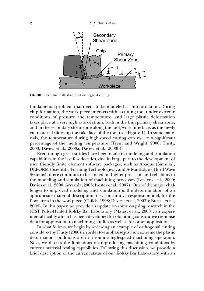
fundamental problem that needs to be modeled is chip formation. Duringchip formation, the work piece interacts with a cutting tool under extremeconditions of pressure and temperature, and large plastic deformationtakes place at a very high rate of strain, both in the thin primary shear zone,and in the secondary shear zone along the tool=work interface, as the newlycut material slides up the rake face of the tool (see Figure 1). In some mate-rials, the temperature during high-speed cutting can rise to a significantpercentage of the melting temperature (Trent and Wright, 2000; Tlusty,2000; Davies et al., 2003a; Davies et al., 2003b).
Even though great strides have been made in modeling and simulationcapabilities in the last few decades, due in large part to the development ofuser friendly finite element software packages, such as Abaqus (Simulia),DEFORM (Scientific Forming Technologies), and AdvantEdge (Third WaveSystems), there continues to be a need for higher precision and reliability inthe modeling and simulation of machining processes (Ivester et al., 2000;Davies et al., 2000; Arrazola, 2003; Ivester et al., 2007). One of themajor chal-lenges to improved modeling and simulation is the determination of anappropriate material description, i.e., constitutive response model, for theflow stress in the workpiece (Childs, 1998; Davies, et al., 2003b; Burns, et al.,2004). In this paper, we provide an update on some ongoing research in theNIST Pulse-Heated Kolsky Bar Laboratory (Mates, et al., 2008), an experi-mental facility which has been developed for obtaining constitutive responsedata for application to machining studies as well as for other applications.
In what follows, we begin by reviewing an example of orthogonal cuttingconsideredbyTlusty (2000), inorder toemphasize justhowextreme theplasticdeformation conditions are in a routine high-speed machining operation.Next, we discuss the limitations on reproducing machining conditions bycurrent material testing capabilities. Following this discussion, we provide abrief description of the current status of our Kolsky Bar Laboratory, with an
FIGURE 1 Schematic illustration of orthogonal cutting.
2 T. J. Burns et al.
emphasis on its uniquepulse-heating capabilities for rapidlypre-heating a sam-ple, and then holding it at a prescribed temperature for up to several seconds,prior to performing a compression test. In addition, we outline some of ourcurrent experimental work in the laboratory that is aimed at providingimproved stress-strain data formachining applications. This researchprogramis based on a combination of pulse heating, followed by impact testing, andfinally by post-test metallurgical analysis of a sample.
After this introductory and background discussion, we present theresults of some recent experiments we have performed on AISI 1075 steel,as part of some ongoing research on the dependence of the flow stress incarbon steels upon the heating rate and time at temperature of thematerial. We show that, as the result of a phase transformation from thestronger bcc pearlitic structure to a structure that includes less-strong fccaustentite under pulse-heating conditions, there is a decrease in flow stressby approximately 50%.
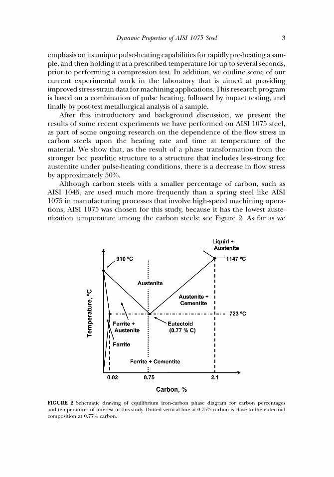
Although carbon steels with a smaller percentage of carbon, such asAISI 1045, are used much more frequently than a spring steel like AISI1075 in manufacturing processes that involve high-speed machining opera-tions, AISI 1075 was chosen for this study, because it has the lowest auste-nization temperature among the carbon steels; see Figure 2. As far as we
FIGURE 2 Schematic drawing of equilibrium iron-carbon phase diagram for carbon percentagesand temperatures of interest in this study. Dotted vertical line at 0.75% carbon is close to the eutectoidcomposition at 0.77% carbon.
Dynamic Properties of AISI 1075 Steel 3
have been able to determine, no high-strain-rate, high-temperature consti-tutive data have been published for this material; however, Sandvik (1996)gives a specific cutting force of 2239 N=mm2 for unalloyed carbon steel witha carbon content of less than 0.8%. The AISI 1075 test samples used in thisstudy were carefully heat treated prior to testing, so that they had a uniformpearlitic microstructure. Although the primary goal of the work presentedhere was not to develop a specific constitutive response model for AISI1075, we discuss the challenge that the data given in this paper pose forthe development of a conventional fixed-parameter constitutive model, likethat of Johnson and Cook (1983), for the flow stress of this material.
CHIP FORMATION
Orthogonal Machining of Carbon Steel
Following Tlusty (2000), consider chip formation during orthogonalmachining of AISI 1035 steel, with the following parameters: uncut chipthickness h¼ 0.2mm, chip width b¼ 6mm, shear zone thicknessd¼ 0.02mm, cutting speed V¼ 3m=s, rake angle a¼ 10�, and shear planeangle u¼ 28� (see Figure 1). Because plastic deformation in non-porousmetals conserves volume, the normal speed of the work material as it flowsthrough the primary shear zone has the constant value VN¼V sin(u)¼1.41m=s. The corresponding shearing speed of the material entering theprimary shear zone is given by VS¼V cos(u)=cos(u� a)¼ 3.11m=s. Thecorresponding chip speed, which is the speed at which the chip moves rela-tive to the tool along the tool face, can be shown to be VC¼V sin(u)=cos(u� a)¼ 1.48m=s. Note that VN and VC differ only by about 5% in thisexample.
Using a method due to Piispanen (1948), the shear strain in the pri-mary shear zone may be estimated by c¼VS=VN¼ cos(a)=[sin(u) cos(u�a)]¼ 221%, which is very large. The corresponding average shear strainrate can then be estimated by _cc¼ c=Dt1, where Dt1¼ d=VN¼ 1.42� 10�5 sis the time interval required to deform an element of the work material intoa corresponding element of the chip; this gives _cc¼ 1.56� 105 s�1, which isalso very large. At the slower cutting speed of 2m=s, Tlusty estimates thetemperature near the chip=tool interface to be about 900�C. This is consist-ent with the temperature measured in AISI 1045 steel at 3.2m=s by Davieset al. (2003a). The chip remains in contact with the tool over a contactlength that we estimate, following Tlusty again, to be four times the unde-formed chip thickness, L¼ 4h¼ 0.8mm, so that d «L. If the uncut materialentering the primary shear zone is at room temperature T0¼ 25�C, thisgives a huge thermal gradient of approximately (900�T0)=L¼ 1.09�106 �Cm�1. If we estimate the time required for the deformation in the
4 T. J. Burns et al.
secondary shear zone to take place by Dt2¼L=VC, then Dt2¼ 5.41�10�4 s. Using Dt2 as an estimate of the time required to heat the workmaterial from room temperature up to the maximum temperature, thisgives an average heating rate of (900 –T0)=Dt2¼ 1.62� 106 �C s�1, whichis also very high.
Constitutive Response Data
Ideally, a carefully designed orthogonal cutting operation could beused for the determination of material constitutive properties for the mod-eling of machining processes. During continuous chip formation, the pro-cess is steady state, and the strain, strain rate, and temperature are of thecorrect orders of magnitude for machining. Although considerable pro-gress has been made in the measurement of aspects of orthogonal metalcutting, the best attempts to date to identify constitutive parameters usingthis method still require a considerable amount of analytical modeling; see,e.g., (Tounsi et al., 2002; Ozel and Zeren, 2006). Thus, this approach can-not yet be viewed entirely as one of making improved experimental mea-surements. There are also questions about the uniqueness of theconstitutive model parameters that are obtained from cutting experiments(Ozel, 1998).
The most common experimental method that is currently used forobtaining constitutive response data for finite-element modeling ofmachining, as well as for more general purposes, is the split-Hopkinsonpressure bar (SHPB) (Gray, 2000). This instrument is also known asthe Kolsky bar, after the man who made a number of improvements toHopkinson’s experimental design (Kolsky, 1949). Using this method, theconstitutive response data required for the deformation processes modeledby these sophisticated software packages are obtained under conditionsthat do not approach those that occur during high-speed machining; see,e.g., Jaspers and Dautzenberg (2002a, 2002b).
In particular, the maximum strain rates that are typically attained in aKolsky bar test are �1� 104 s�1. There are also methods for loading thesample in tension (Nicholas, 1981) and in torsion (Hartley et al., 1985),to approximately the same strain rates, on the Kolsky bar. Typical maximumstrains obtained with a compressional Kolsky bar are �50%; larger strains,�1, can be obtained with the torsional bar test. Thus, with these methods,the strain rate is an order of magnitude smaller than is routinely observedin high-speed machining. Additionally, when the influence of thermalsoftening on material strength is measured during a Kolsky bar test, thetraditional method, in the case of the compression test, is to preheat thesample slowly in situ, followed by dynamic loading of the sample. This
Dynamic Properties of AISI 1075 Steel 5

heating method also preheats the sections of the elastic bars adjacent to thesample, which limits the maximum attainable sample temperature andcomplicates the data analysis (Sharpe, 2008).
Improvements in the heating rate and the attainable uniform sampletemperature prior to testing in a Kolsky bar have been made. An inductionmethod has been developed for in situ pre-heating in the dynamic tensiletest (Rosenberg et al., 1986). Frantz, et al. (1984) have developed a methodfor pre-heating the sample in situ using a furnace, and then rapidly bring-ing the pressure bars into contact with the sample, prior to the dynamiccompression test (also see Jaspers and Dautzenberg (2002b) andNemat-Nasser (2009)). In the next section, a description is given of ourown method of in situ resistive pre-heating in the compression test (Mateset al., 2008).
Nevertheless, as far as we know, there is currently no experimentalmethod that can simultaneously produce the high heating rates and hightemperature conditions that frequently occur during modern machiningoperations, and also accurately measure the dynamic stress-strain responseof a material. It follows that when constitutive models fit with these data areused to predict material response for machining simulations, the results ofthese calculations are subject to the criticism that they are based on extra-polations to much larger strains, strain rates, and heating rates, and muchsmaller times at high temperature, than the experimental data on whichthe models are based. Thus, there is still a considerable need for improve-ments in experimental methods for the determination of constitutiveresponse data for the modeling and simulation of high-speed machiningoperations (Ivester et al., 2000).
THE NIST KOLSKY BAR LABORATORY
Split-Hopkinson Pressure Bar
The NIST Kolsky Bar is a precision engineered split-Hopkinson press-ure bar (Rhorer et al., 2002). Two high strength maraging steel bars, eachof 1.5m length and 15mm diameter, are mounted on bearings to enableeasy sliding of the bars in the axial direction and to resist bending inother directions. A cylindrical sample of the material to be tested isinserted between the two long bars, carefully aligned for axial symmetry,so that, ignoring radial effects, the data can be analyzed usingone-dimensional wave theory. One of the long bars, called the incidentbar, is impacted by a striker, launched by an air gun. The striker is a muchshorter bar made from the same maraging steel, with the same diameter,as the two long bars.
6 T. J. Burns et al.

In this way, the sample is rapidly loaded by a compressive wave.Because there is an impedance mismatch at the sample, and becausethe system can be modeled fairly accurately by one-dimensional linearelastic wave theory, when the compressive wave arrives at the bar=sampleinterface, the difference in impedance between the bar and the sampleresults in a splitting of the input wave into a tensile wave that is reflectedback into the incident bar, and a wave that compresses the smaller-diameter sample sufficiently so that it is rapidly and permanentlydeformed plastically. This compressive wave then propagates into thesecond long bar, called the transmitted bar. The system is designed so thatthe only plastic deformation that occurs is in the sample. By means ofstrain gauges mounted at the midpoints of the input and transmitted barsand one-dimensional elastic wave analysis, the stress vs. strain response ofthe sample can be obtained.
Subsecond Thermophysics Laboratory
What makes the NIST apparatus unique is the fact that it has been com-bined with an existing controlled resistive-heating facility, the NIST Subse-cond Thermophysics Laboratory (Basak et al., 2004). This laboratory wasoriginally developed to measure physical properties of metals at high tem-perature, such as the critical point at melting of a pure metal, using rapidresistive heating and non-contact thermometry. It has the capability topre-heat an experimental sample extremely rapidly, in situ, using preciselycontrolled DC electrical current.
Combined Pulse-Heated Kolsky Bar Apparatus
To combine the two systems, non-conducting (Delrin1 acetal plastic)bearings are used to support the two long bars, with the exception of thebearing at the support at the end of each bar nearest to the sample. Atthese two interior supports, custom-made graphite-lined metal sleevesare used. Heavy-duty welding cables connect the interior pair of supportposts to the DC electrical circuit. The interior support posts are isolatedelectrically from the surrounding support structure. By means of thisdesign, the incident and transmitted bars can be used to conduct a rapid,controlled DC pulsed electric current of up to several hundred amperesthrough a metal Kolsky bar sample; see Figure 3. The typical sample sizethat we use in this system is 2mm thick and 4mm in diameter, which issmaller than usual for a 15mm diameter Kolsky bar system. The reasonfor using this smaller size is to guarantee that the sample will heat up
Dynamic Properties of AISI 1075 Steel 7

much more rapidly than the interior ends of the two long elastic barsduring a test.
The sample temperature is controlled by means of a fast-responsepyrometer. The signal from the pyrometer is used to pulse the heating cur-rent with sufficient rapidity that the sample quickly reaches and maintains apre-selected temperature. Using this method, a sample temperature uni-formity of 20�C or less can be obtained (Mates et al., 2008). The thermalcontrol system shuts off the DC current within a few milliseconds priorto firing the air gun to launch the striker bar into the incident bar. Oncethe test is over, the sample typically remains compressed between the bars,and it cools rapidly.
By combining the thermophysics laboratory with a Kolsky bar, we nowhave a facility for high-strain-rate testing of metal samples that have beenpulse-heated prior to stress loading. With the heating rates and tempera-ture control capabilities of this system, together with non-contact thermalmeasurements, a uniform temperature can reliably be introduced into asample extremely rapidly. In its present configuration, the NIST KolskyBar facility can measure the flow stress of metals at heating rates of up to6� 103 �C s�1. While this heating rate is still orders of magnitude smallerthan the �1� 106 �C s�1 that is routinely observed in high-speed machiningprocesses, as discussed in the example in the preceding section, it is muchmore rapid than the rates at which material samples are pre-heated usingmore traditional methods.
In the next section, new data are presented from a sequence ofpulse-heated high-strain-rate Kolsky bar experiments that were performedon AISI 1075 steel at temperatures that were both below and above theaustenite formation temperature, 723�C. As discussed previously, this iscertainly within the minimum and maximum range of temperatures thatroutinely occur during high-speed machining of carbon steels.
FIGURE 3 Schematic drawing of the NIST Kolsky Bar with DC current pulse-heating capability.
8 T. J. Burns et al.

APPLICATION TO AISI 1075 STEEL
Discussion of Microstructure
During a high-speed machining operation on a carbon steel, thematerial undergoes rapid heating. Furthermore, because the resulting chipis quickly exposed to air or to a cooling fluid, upon separation from thetool, the work material is rapidly quenched. It follows that it undergoes arapid heating-cooling cycle, much like a pulse-heated Kolsky bar sample.Although the Kolsky bar heating rate is not as rapid as in machining, it isstill fast enough to study some interesting dependence of the flow stresson the rate of heating and the time at temperature.
At room temperature, an iron-carbon alloy such as AISI 1075 is typicallya solid mixture of two body-centered-cubic (bcc) crystalline materials, fer-rite (iron) and cementite (iron carbide) (Thelning, 1984). The steel usedin our tests was heat treated to obtain a uniform initial microstructure of100% fine pearlite. In this microstructure, the ferrite and cementite parti-cles form into thin lamellae, or plates, which alternate within the structure;see Figure 4. With 0.75% carbon content, AISI 1075 steel is near the eutec-toid composition (0.77% carbon), and its eutectoid temperature is close to723�C, which is the lowest among the carbon steels (Figure 2).
When heated to a temperature exceeding the eutectoid temperature,and then maintained isothermally, pearlite undergoes a phase transform-ation into homogeneous austenite, a face-centered cubic solid solution,also called the c-phase, which is unstable at temperatures below the eutec-toid. This phase transformation results from the diffusion of carbon intosolid solution with the iron. What this means from the point of view ofthe present discussion is that, under isothermal heating conditions, this
FIGURE 4 AISI 1075 samples were heat-treated to obtain a uniform, nearly 100% fine pearliticmicrostructure prior to testing.
Dynamic Properties of AISI 1075 Steel 9

material transforms to austenite (100% c-phase), a face-centered-cubicstructure (fcc), at the lowest temperature of the carbon steels. Because ofthis property, due to its location on the iron-carbon phase diagram, thisparticular alloy enables a measurement to be made most easily of thestrength difference that occurs in a carbon steel as a result of the transform-ation from one single-phase bcc material (pearlite) that is very strong, toanother single phase fcc material (austenite) that is less strong.
As with all diffusion processes, a sufficient amount of time is required forequilibrium to be attained. If the time at temperature is too short, the orig-inal pearlite will not have enough time to transform into austenite. As thetime at temperature increases, an increasing percentage of the pearlite willtransform into austenite, so that there will be a non-equilibrium solid sol-ution consisting partially of austenite. When austenite is cooled very rapidly,i.e., quenched, to room temperature, it transforms into martensite. Marten-site consists of fine, irregular plate-like crystals having the composition ofthe austenite from which it formed. Since martensite cannot form fromquenched pearlite, the appearance of martensite in a tested sample indi-cates that it had undergone austenitization prior to quenching. Thus, byusing metallurgical techniques to measure the percentage of martensitein the material after a rapid heating-cooling cycle, the percentage of austen-ite that was present during the rapid heating phase can be determined.
Kolsky Bar Data
As has already been discussed above, the samples were heat treatedprior to testing, so that the initial microstructure was uniformly fine pear-litic; see Figure 4. This was done in order to guarantee that any loss ofstrength due to austenitization would be a maximum, because we wereunsure of what the magnitude of this difference in measured flow stresswould be. We are unaware of any published estimates of this strength differ-ence in a carbon steel that depends upon on the heating rate and the timeat temperature of the test material.
A series of Kolsky bar tests were performed on samples of thisheat-treated AISI 1075 steel, at room temperature and also on pulse-heatedsamples. The flow stress and the true strain rate measured in one of theroom-temperature tests are shown in Figure 5. In the pulse-heated tests,the sample was heated to the test temperature within approximately 1.5seconds in two stages, and then it was held at temperature for approxi-mately an additional 3.5 seconds, before the compression wave reachedthe sample.
A typical heating history is shown in Figure 6. The sample temperatureis controlled using a millisecond resolution Near Infrared Micro PYrometer
10 T. J. Burns et al.

(NIMPY) that serves as a feedback sensor for the DC power supply. TheNIMPY is not operational below 300�C. To avoid problems with electricalarcing, the samples were first heated with a lower current to an intermedi-ate temperature that was much less than the eutectoid temperature, in atime on the order of 1 s. During the second heating stage, the samples wereheated to the final test temperature at a rate of about 1000�C s�1. The cur-rent was then shut off, and the samples were mechanically deformed to atrue strain on the order of 25%�35% within the next 100 ms; see Mateset al. (2008) for more details on the sample pre-heating system. Thetrue strain rate in all of these tests was approximately 3500 s�1. After thesample was compressed, the cooling rate in our experiments, as determ-ined from the thermocouple cooling history, was approximately 500�C s�1.
Pulse-heated compression tests were performed at temperatures bothconsiderably below and above the eutectoid temperature, and also at asequence of temperatures at smaller increments on either side of the tran-sition temperature. Thus, the initial sample pre-heating state could bevisualized as a point on the dotted vertical line in Figure 2. It is less easyto summarize the states of all of the samples after first pre-heating and thenrapidly compressing them. In Figure 7, the flow stress at 10% true strain vs.the measured test temperature of each pulse-heated sample is plotted. The
FIGURE 5 Results of Kolsky bar test on a room-temperature sample of AISI 1075 steel. True stress at10% true strain is approximately 1140MPa; true strain rate is approximately 3500 s�1..
Dynamic Properties of AISI 1075 Steel 11

FIGURE 7 Kolsky bar experimental data on AISI 1075 steel; pearlitic room-temperature samples werepulse-heated and then held at temperature for 3.5 s; vertical line denotes the eutectoid temperature(723�C); squares denote the flow stress at 10% true strain,�3500 s�1 true strain rate; error bars denote 2r.
FIGURE 6 Example temperature histories of test samples pulse-heated to below (solid curve) andabove (dashed curve) the transition temperature prior to a high strain rate compression test. The sam-ple temperature is controlled using a millisecond resolution Near Infrared Micro PYrometer (NIMPY)that serves as a feedback sensor for the DC power supply; the NIMPY is not operational below 300�C.The samples were first heated with a lower current to an intermediate temperature that was much lessthan the eutectoid temperature, in a time on the order of 1 s. They were then heated to the testtemperature in a faster second stage, at a rate of about 1000�C s�1.
12 T. J. Burns et al.

error bars denote the 2r uncertainty in the temperature measurements.The 2r uncertainty in the stress measurements was estimated to be no morethan 5%; for this reason, these error bars were not plotted, since there wasmuch more uncertainty in the temperature measurements. The randomerror propagation techniques that were used to estimate these measure-ment uncertainties may be found in Mates et al. (2008).
The experimental data show that across the transition temperature,there is a reduction in flow stress of about 50%. A metallurgical analysiswas performed on the post-test samples, in order to correlate the micro-structure of the material with the measured flow stress. The results indi-cated that, in all of the tests conducted at temperatures that were at leastseveral degrees above the transition temperature (723�C), the post-test sam-ple microstructures were fully martensitic with no trace of retained pearlite,indicating that a complete transformation had occurred in these tests; seeFigure 8.
On the other hand, all of the samples that had been pre-heated to tem-peratures below the transition temperature contained untransformedpearlite, indicating that no transition took place in these tests; seeFigure 9. In a test in which the sample had been pre-heated to a tempera-ture of 725�C, which is very close to the transition temperature, thepost-test metallurgical analysis showed an altered coarsened pearlitic struc-ture. In this test, the sample failed to quench rapidly enough to form mar-tensite, meaning that it was difficult to tell whether austenite, pearlite, or amixture of the two phases was present when the compression test occurred;see Figure 10. However, the magnitude of the flow stress in this test indi-cated that most of the pearlite had transformed into austenite. In the next
FIGURE 8 AISI 1075 test sample that was pulse-heated to 752�C, and then rapidly compressed in aKolsky bar apparatus. The microstructure is fully martensitic, with no trace of retained pearlite, indicat-ing that a complete transformation from pearlite to austenite had occurred prior to the compressiontest.
Dynamic Properties of AISI 1075 Steel 13

section, the implications of the test results presented in Figure 7 for theconstitutive response modeling of AISI 1075 are discussed.
CONSTITUTIVE MODELING OF AISI 1075 DATA
Johnson-Cook Flow Stress Model
The Johnson-Cook flow stress model (Johnson and Cook, 1983) is acommonly used constitutive response function for finite-element
FIGURE 10 AISI 1075 test sample that was pulse-heated to 725�C, and then rapidly compressed in aKolsky bar apparatus. Post-test metallurgical analysis showed an altered coarsened pearlitic structure.In this test, the sample failed to quench rapidly enough to form martensite, meaning that it was difficultto tell whether austenite, pearlite, or a mixture of the two phases was present when the compression testoccurred to austenite.
FIGURE 9 AISI 1075 test sample that was pulse-heated to 588�C, and then rapidly compressed in aKolsky bar apparatus; the microstructure is still fine pearlitic, indicating that no transition to austeniteoccurred during the test.
14 T. J. Burns et al.

simulations of the rapid plastic deformation of metals; see, e.g., Meyers(1994); Jaspers and Dautzenberg (2002b). This phenomenological modelexpresses the von Mises flow stress, r as a function of the true strain, truestrain rate, and temperature,
r ¼ A þ B�een½ � 1þ C ln _�ee�ee�� �
1� T �ð Þm½ �: ð1Þ
In Equation 1, �ee is the equivalent plastic strain, _�ee�ee� ¼ _�ee�ee=_�ee�ee0 is the dimension-
less true strain rate, _�ee�ee0 ¼ 1:0 s�1, and T� is the homologous temperature, adimensionless quantity that is defined as follows,
T � ¼ T � T0
TM � T0: ð2Þ
Here, T is the temperature in degrees C, T0¼ 20�C is the initial tempera-ture, and TM is the melting temperature of the material. A, B, C, n, andm are five material constants that are fit to experimental data. Note thatEquation 1 is a product of three power-law expressions, with each terminvolving only one of the independent variables.
The purely empirical Johnson-Cook model for a specific material isusually determined in three steps; see, e.g., Meyers (1994). First, the para-meters in the leading term are determined using quasi-static tension or tor-sion data; A is the yield strength of the material, and B and n estimate itsstrain-hardening behavior. Second, the thermal softening fraction KT isdetermined by computing the ratio of the stress in a heated test to thatin a room-temperature test at the same strain rate. It then follows that
m ¼ ln ð1� KT Þ= lnT �: ð3Þ
In the third step, the strain-rate sensitivity coefficient C is determinedby using the flow stress values at a fixed strain from two different room tem-perature tests, performed at two different strain rates. Some authors useoptimization methods to determine the best-fit parameter values for setsof data on a given material that have been measured experimentally; see,e.g., Milani, et al. (2006).
Application to AISI 1075 Data
Now, consider the AISI 1075 data given in Figure 7. All of these experi-ments were performed at a nominal strain rate of approximately 3500 s�1.Therefore, if we assume that the top curve of the high strain-rate room tem-perature test has been well-fit by finding the coefficients A, B, C, and n inEquation 1, it follows that the flow stress at 10% strain and 3500 s�1 will
Dynamic Properties of AISI 1075 Steel 15

approximately be equal to 1140MPa. Keeping the strain fixed at 10% andthe strain rate fixed at 3500 s�1, Equation 1 can be written as
r ¼ 1� T �ð Þm½ � � 1140MPa: ð4Þ
In Figure 11, the isolated circle at T0¼ 25�C and r¼ 1140MPa is the flowstress at T¼T0, so that T� ¼ 0. The pulse-heated data at 10% strain givenin Figure 7 are also re-plotted in Figure 11. Using the cold flow stress atT0 as the initial point, and fixing the melting temperature at TM¼ 1516�Cin Equation 2, Equation 4 is plotted in Figure 11 with m¼ 1.6 (uppercurve), m¼ 1.0 (center line), and m¼ 0.7 (lower curve) on the temperatureinterval [T0, 1000
�C].A number of conclusions can be drawn from Figure 11. With the
thermal-softening parameter value m¼ 1.6, Equation 4 predicts the flowstress fairly well at elevated temperatures that are below 723�C. On theother hand, using the thermal parameter value m¼ 0.7, Equation 4 predictsthe flow stress values above 723�C fairly well. This is why these two values ofm were chosen. However, for the carbon steels AISI 1006 and AISI 1045, ithas been found from experimental data on slowly pre-heated samples by anumber of authors that the thermal parameter m � 1.0 (Johnson and Cook,
FIGURE 11 Flow stress at 10% true strain. Upper (dash-dot) curve: m¼ 1.6; middle (solid) curve:m¼ 1.0; lower (dash) curve: m¼0.7. Vertical line denotes eutectoid temperature. Circle is experimentaldata from room temperature test; squares are experimental data from tests in which sample waspulse-heated and then held at constant temperature for �3.5 s before impact.
16 T. J. Burns et al.
1983; Meyers, 1994; Jaspers and Dautzenberg, 2002b; Ozel and Karpat,2007). Use of m¼ 1 in Equation 4 provides a poor prediction for all butone of the pulse-heated data points. Overall, the Johnson-Cook model withconstant m does a poor job of fitting all of the data in Figure 11, where evi-dently there is a phase transition in the microstructure at the eutectoidtemperature from a pearlite to austenite.
DISCUSSION AND CONCLUDING REMARKS
We have presented new experimental results on pulse-heated AISI 1075steel. These data were shown to present a constitutive modeling challenge,because of a phase transformation from pearlite to austenite that tookplace in the material microstructure when the sample was rapidlypre-heated to a temperature above 723�C prior to rapid compression test-ing. In an experimental study of austenite formation in 0.75% carbon steelusing dilatometry, Rose and Strassburg (1956) and Thelning (1984) havepublished heating time-temperature transformation (TTT) curves thatindicate that a time of 3.5 seconds at high temperature is insufficient forthe transformation to austenite to run to completion. Based on this, weexpected that a flow stress-temperature curve like the upper curve inFigure 11 with m> 1 would fit our experimental data on pulse-heated AISI1075 fairly well. However, this is clearly not the case. Therefore, the datapresented here are very interesting, because they show that there is indeedevidence of the phase transformation, even for this relatively short time athigh temperature.
We are unaware of any studies that have attempted to measure strengthdifferences that may occur in a carbon steel as the result of phase transfor-mations under the conditions of simultaneous very rapid heating andcompression that occur during high-speed machining. Although ourexperimental work involves pre-heating a sample prior to loading it, webelieve that the new constitutive response data presented in this papermay help to explain why the results of many finite-element simulations ofhigh-speed machining operations, while providing much useful insight intothe physics of these operations, often fail to give good predictions of essen-tial quantities such as forces and temperatures; see, e.g., Arrazola (2003).
As already mentioned, carbon steels with a smaller percentage of car-bon, such as AISI 1045, are of much more interest than AISI 1075 forthe modeling and simulation of manufacturing processes that involvehigh-speed machining operations. For this reason, no attempt was madeto construct a complete constitutive model for AISI 1075 in the presentstudy. However, it would be of great interest to investigate whether ornot a series of dynamic pulse-heated tests on samples of AISI 1045 steel,
Dynamic Properties of AISI 1075 Steel 17

prepared from commercial bar stock, show a response similar to thatdescribed by Equation 4, with m> 1 for experiments in which the testingtemperature is less than the eutectoid temperature, and m< 1 for experi-ments in which the testing temperature is greater than the eutectoid tem-perature. This will be the subject of a subsequent paper.
DISCLAIMER
Commercial products are identified in order to specify certain proce-dures or equipment used. In no case does such identification imply rec-ommendation or endorsement by the National Institute of Standards andTechnology, nor does it imply that the identified products are necessarilythe best available for the purpose.
NOMENCLATURE
h chip thicknessb chip widthd shear zone thicknessV cutting speeda rake angleu shear plane angleVN work material speed normal to primary shear zoneVS shearing speed of work material in direction of primary shear zoneVC chip speed speed parallel to the face of the toolc shear strain_cc shear strain rateDt1 time work material spends in primary shear zoneL contact length of chip along face of toolDt2 time work material spends in secondary shear zoner von Mises flow stress�ee equivalent plastic strain_�ee�ee�
dimensionless true strain rate_�ee�ee0 reference strain rate for non-dimensionalizationT � homologous temperatureT temperatureT0 initial temperatureTM melting temperatureA,B,C,m,n Johnson-Cook empirical material constants
REFERENCES
Arrazola, P.-J. (2003) Modelisation numerique de la coupe: Etude de sensibilite des parametres d’entree et identifi-cation du frottement entre outil-copeau, Phd. Thesis, E.C. Nantes, France.
18 T. J. Burns et al.

Basak, D.; Yoon, H.W.; Rhorer, R.; Burns, T.J.; Matsumoto, T. (2004) Temperature control of pulseheated specimens in a Kolsky bar apparatus using microsecond time-resolved pyrometry. Inter-national Journal of Thermophysics, 25(2): 561–574.
Burns, T.J.; Davies, M.A.; Rhorer, R.L.; Basak, D.; Yoon, H.W.; Fields, R.J.; Levine, L.E.; Cao, Q.; Cooke,A.L.; Whitenton, E.P.; Kennedy, M.D.; Ivester, R. (2004) Influence of heating rate on flow stress inhigh-speed machining processes. In Proceedings of the 7th CIRP International Workshop on Modeling ofMachining Operations, Cluny, France.
Childs, T.H.C. (1998) Material property needs in modeling metal machining. Journal of Machining Scienceand Technology, 2(2): 303–316.
Davies, M.A.; Yoon, H.; Schmitz, T.L.; Burns, T.J.; Kennedy, M.D. (2003a) Calibrated thermal microscopyof the tool-chip interface in machining. Journal of Machining Science and Technology, 7(2): 166–190.
Davies, M.A.; Cao, Q.; Cooke, A.L.; Ivester, R. (2003b) On the measurement and prediction of tempera-ture fields in machining AISI 1045 steel. Annals of the CIRP, 52(1): 77–80.
Frantz, C.E.; Follansbee, P.S.; Wright, W.T. (1984) Experimental techniques with the split Hopkinsonpressure bar. In High Energy Rate Forming; Berman, I.; Schroeder, J.W. (Eds.), ASME: New York,pp. 229–236.
Gray, G.T. III (2000) Classic split-Hopkinson pressure bar testing. In Metals Handbook 10th Edition,American Society of Metals: Materials Park, Ohio, Volume 8, pp. 462–476.
Hartley, K.A.; Duffy, J.; Hawley, R.E. (1985) The torsional Kolsky (split-Hopkinson) bar. In Metals Hand-book. 9th Edition, American Society of Metals: Materials Park, Ohio, Volume 8, pp. 218–228.
Ivester, R.; Kennedy, M.; Davies, M.; Stevenson, R.; Thiele, J.; Furness, R.; Athavale, S. (2000) Assessmentof machining models: Progress report. Journal of Machining Science and Technology, 4(3): 511–538.
Ivester, R.; Whitenton, E.; Heigel, J.; Marusich, T.; Arthur, C. (2007) Measuring chip segmentation byhigh-speed microvideography and comparison to finite-element modeling simulations. In Proceed-ings of the 10th CIRP International Workshop on Modeling of Machining Operations, Calabria, Italy..
Jaspers, S.P.F.C.; Dautzenburg, J.H. (2002a) Material behavior in metal cutting: Strains, strain rates, andtemperatures in metal cutting. Journal of Materials Processing Technology, 121: 123–135.
Jaspers, S.P.F.C.; Dautzenburg, J.H. (2002b) Material behavior in conditions similar to metal cutting:flow stress in the primary shear zone. Journal of Materials Processing Technology, 122: 322–330.
Johnson, G.J.; Cook, W.H. (1983) A constitutive model and data for metals subjected to large strains,high strain rates, and temperatures. In Proceedings of the 7th Symposium on Ballistics, The Hague,pp. 541–547.
Kolsky, H. (1949) An investigation of the mechanical properties of materials at very high rates of load-ing. Proceedings of the Physical Society of London, B62: 676–700.
Mates, S.P.; Rhorer, R.; Whitenton, E.; Burns, T.; Basak, D. (2008) A pulse-heated Kolsky bar techniquefor measuring flow stress of metals subjected to high loading and heating rates. ExperimentalMechanics, 48: 799–807.
Meyers, M.A. (1994) Dynamic Behavior of Materials. John Wiley & Sons: New York, NY.Milani, A.S.; Dabboussi, W.; El-Lahham; C.; Nemes J.A.; Aberyaratne, R.C. (2006) On obtaining material
parameters for general purpose finite element models. In Proceedings of the 17th IASTEDInternational Conference on Modelling and Simulation, Montreal, QC, Canada.
Nemat-Nasser, S. (2009) Plasticity: A Treatise on Finite Deformation of Heterogeneous Inelastic Materials.Cambridge University Press: Cambridge, UK.
Nicholas, T. (1981) Tensile testing of materials at high rates of strain. Experimental Mechanics, 21:177–185.
Ozel, T. (1988) Investigation of High Speed Flat End Milling Process. PhD Dissertation, The Ohio StateUniversity, Columbus, Ohio.
Ozel, T.; Karpat, Y. (2007) Identification of constitutive material model parameters for high strain ratemetal cutting conditions using evolutionary computational algorithms.Materials and ManufacturingProcesses, 22: 659–667.
Ozel T.; Zeren, E. (2006) A methodology to determine work material flow stress and tool-chip interfacialfriction properties by using analysis of machining. ASME Journal of Manufacturing Science and Engin-eering, 128: 119–129.
Piispanen, V. (1948) Theory of formation of metal chips. Journal of Applied Physics, 19: 876–881.
Dynamic Properties of AISI 1075 Steel 19

Rhorer, R.L.; Davies, M.A.; Kennedy, M.D.; Dutterer, B.S.; Burns, T.J. (2002) Construction and align-ment of a Kolsky bar apparatus. In Proceedings of the American Society for Precision Engineering AnnualConference, St. Louis, MO.
Rose, A.; Strassburg, W. (1956) Darstellung der Austenitbildung untereutektoidischer Stahle inZeit-Temperatur-Auflosungs-Schaubildern. Stahl und Eisen, 76(15): 976–983.
Rosenberg, Z.; Dawicke, D.; Strader, E.; Bless, S.J. (1986) A new technique for heating specimens insplit-Hopkinson bar experiments using induction-coil heaters. Experimental Mechanics, 26(3):275–278.
Sandvik (1996) Modern Metal Cutting – A Practical Handbook. Sandvik Coromant, Fair Lawn, NJ.Tlusty, J. (2000) Manufacturing Processes and Equipment, Prentice-Hall, Upper Saddle River, NJ.Tounsi, N.; Vincenti, J.; Otho, A.; Elbestawi, M.A. (2002) From the basic mechanics of orthogonal metal
cutting toward the identification of the constitutive equation. International Journal of Machine Toolsand Manufacture, 43: 1373–1383.
Trent, E.M.; Wright, P.K. (2000) Metal Cutting. 4th Edition, Butterworth-Heinemann: Boston, MA.
20 T. J. Burns et al.