dynamic ventilation control system
TRANSCRIPT

Dynamic Ventilation Control System
By
Khalique Ahmed
Alonso Gonzalez Sanz
Yun Seong Kim
Final Report for ECE 445, Senior Design, Spring 2017
TA: Vignesh Sridhar
3 May 2017
Project No. 15

Abstract
In standard apartments and homes, a single thermostat may not be able to determine comfortable room temperatures
for every occupant. Consequently, many rooms become either too warm or too cold, and this perspective differs
between occupants. To combat this disparity, we propose modification of pre-existing floor and wall registers to
enable dynamic adjustment of their respective dampers. Opening and closing these dampers enables dynamic control
of airflow.
Our final revision for the course incorporates wireless modification of these dampers. A smartphone communicates
with our unit through Bluetooth Low Energy (BLE). We also provide the building blocks to energy-efficient power
circuitry in order to maximize longevity.
i

Contents
1 Introduction . . . . . . . . . . . . . . . . . . . . . . . . . . . . . . . . . . . . . . . . . . . . . . . . . . . . . . . . . . . . . . . 1
1.1 Objective . . . . . . . . . . . . . . . . . . . . . . . . . . . . . . . . . . . . . . . . . . . . . . . . . . . . . . . . . . . . . . . 1
1.2 Background . . . . . . . . . . . . . . . . . . . . . . . . . . . . . . . . . . . . . . . . . . . . . . . . . . . . . . . . . . . . . 1
1.3 High Level Requirements . . . . . . . . . . . . . . . . . . . . . . . . . . . . . . . . . . . . . . . . . . . . . . . . . . . . 1
2 Design. . . . . . . . . . . . . . . . . . . . . . . . . . . . . . . . . . . . . . . . . . . . . . . . . . . . . . . . . . . . . . . . . . . . 2
2.1 Vent Unit . . . . . . . . . . . . . . . . . . . . . . . . . . . . . . . . . . . . . . . . . . . . . . . . . . . . . . . . . . . . . . . 3
2.1.1 Battery - Voltage Regulator . . . . . . . . . . . . . . . . . . . . . . . . . . . . . . . . . . . . . . . . . . . . . . 3
2.1.2 Undervoltage Lockout (UVLO) . . . . . . . . . . . . . . . . . . . . . . . . . . . . . . . . . . . . . . . . . . . . 3
2.1.3 Pressure Sensor . . . . . . . . . . . . . . . . . . . . . . . . . . . . . . . . . . . . . . . . . . . . . . . . . . . . . . . 3
2.1.4 Servo Motor . . . . . . . . . . . . . . . . . . . . . . . . . . . . . . . . . . . . . . . . . . . . . . . . . . . . . . . . . 3
2.1.5 Microcontroller (MCU). . . . . . . . . . . . . . . . . . . . . . . . . . . . . . . . . . . . . . . . . . . . . . . . . . 3
2.1.6 BLE . . . . . . . . . . . . . . . . . . . . . . . . . . . . . . . . . . . . . . . . . . . . . . . . . . . . . . . . . . . . . . . 4
2.2 Hub Unit . . . . . . . . . . . . . . . . . . . . . . . . . . . . . . . . . . . . . . . . . . . . . . . . . . . . . . . . . . . . . . . 4
2.2.1 Power Supply. . . . . . . . . . . . . . . . . . . . . . . . . . . . . . . . . . . . . . . . . . . . . . . . . . . . . . . . . 4
2.2.2 AC-DC Converter . . . . . . . . . . . . . . . . . . . . . . . . . . . . . . . . . . . . . . . . . . . . . . . . . . . . . 4
2.2.3 Voltage Regulator . . . . . . . . . . . . . . . . . . . . . . . . . . . . . . . . . . . . . . . . . . . . . . . . . . . . . 4
2.2.4 Temperature Sensor . . . . . . . . . . . . . . . . . . . . . . . . . . . . . . . . . . . . . . . . . . . . . . . . . . . . 4
2.2.5 Microcontroller (MCU). . . . . . . . . . . . . . . . . . . . . . . . . . . . . . . . . . . . . . . . . . . . . . . . . . 5
2.2.6 BLE . . . . . . . . . . . . . . . . . . . . . . . . . . . . . . . . . . . . . . . . . . . . . . . . . . . . . . . . . . . . . . . 5
2.3 Smartphone Application . . . . . . . . . . . . . . . . . . . . . . . . . . . . . . . . . . . . . . . . . . . . . . . . . . . . 5
2.4 Calculations . . . . . . . . . . . . . . . . . . . . . . . . . . . . . . . . . . . . . . . . . . . . . . . . . . . . . . . . . . . . . 5
2.5 Software Algorithms . . . . . . . . . . . . . . . . . . . . . . . . . . . . . . . . . . . . . . . . . . . . . . . . . . . . . . . 8
2.5.1 Hub Unit. . . . . . . . . . . . . . . . . . . . . . . . . . . . . . . . . . . . . . . . . . . . . . . . . . . . . . . . . . . . 8
2.5.2 Vent Unit . . . . . . . . . . . . . . . . . . . . . . . . . . . . . . . . . . . . . . . . . . . . . . . . . . . . . . . . . . . 9
3 Results . . . . . . . . . . . . . . . . . . . . . . . . . . . . . . . . . . . . . . . . . . . . . . . . . . . . . . . . . . . . . . . . . . . 10
3.1 Requirements and Verification . . . . . . . . . . . . . . . . . . . . . . . . . . . . . . . . . . . . . . . . . . . . . . . . 10
3.2 MCU Programming. . . . . . . . . . . . . . . . . . . . . . . . . . . . . . . . . . . . . . . . . . . . . . . . . . . . . . . . 10
3.3 Smartphone Application . . . . . . . . . . . . . . . . . . . . . . . . . . . . . . . . . . . . . . . . . . . . . . . . . . . . 10
3.4 Power Consumption . . . . . . . . . . . . . . . . . . . . . . . . . . . . . . . . . . . . . . . . . . . . . . . . . . . . . . . 12
4 Cost . . . . . . . . . . . . . . . . . . . . . . . . . . . . . . . . . . . . . . . . . . . . . . . . . . . . . . . . . . . . . . . . . . . . . 13
4.1 Parts . . . . . . . . . . . . . . . . . . . . . . . . . . . . . . . . . . . . . . . . . . . . . . . . . . . . . . . . . . . . . . . . . . 13
ii

4.2 Labor . . . . . . . . . . . . . . . . . . . . . . . . . . . . . . . . . . . . . . . . . . . . . . . . . . . . . . . . . . . . . . . . . . 13
4.3 Grand Total . . . . . . . . . . . . . . . . . . . . . . . . . . . . . . . . . . . . . . . . . . . . . . . . . . . . . . . . . . . . . 13
5 Conclusion. . . . . . . . . . . . . . . . . . . . . . . . . . . . . . . . . . . . . . . . . . . . . . . . . . . . . . . . . . . . . . . . . 14
5.1 Accomplishments . . . . . . . . . . . . . . . . . . . . . . . . . . . . . . . . . . . . . . . . . . . . . . . . . . . . . . . . . 14
5.2 Uncertainties . . . . . . . . . . . . . . . . . . . . . . . . . . . . . . . . . . . . . . . . . . . . . . . . . . . . . . . . . . . . 14
5.3 Future Work and Alternatives . . . . . . . . . . . . . . . . . . . . . . . . . . . . . . . . . . . . . . . . . . . . . . . . 14
5.4 Safety. . . . . . . . . . . . . . . . . . . . . . . . . . . . . . . . . . . . . . . . . . . . . . . . . . . . . . . . . . . . . . . . . . 14
5.5 Ethical Considerations. . . . . . . . . . . . . . . . . . . . . . . . . . . . . . . . . . . . . . . . . . . . . . . . . . . . . . 15
References . . . . . . . . . . . . . . . . . . . . . . . . . . . . . . . . . . . . . . . . . . . . . . . . . . . . . . . . . . . . . . . . . . . 16
A Requirements and Verification Table . . . . . . . . . . . . . . . . . . . . . . . . . . . . . . . . . . . . . . . . . . . . . . 17
B Physical Design Rendering . . . . . . . . . . . . . . . . . . . . . . . . . . . . . . . . . . . . . . . . . . . . . . . . . . . . . 20
C Schematics. . . . . . . . . . . . . . . . . . . . . . . . . . . . . . . . . . . . . . . . . . . . . . . . . . . . . . . . . . . . . . . . . 21
D Simulations . . . . . . . . . . . . . . . . . . . . . . . . . . . . . . . . . . . . . . . . . . . . . . . . . . . . . . . . . . . . . . . . 23
iii

1 Introduction
1.1 Objective
Controlling heating and cooling in a home or apartment typically relies on a HVAC system with only a single
thermostat. The temperature sensor on this thermostat determines the necessary temperature changes for
the rest of the rooms. With this single thermostat configuration, there is a chance that several rooms are not
meeting temperature expectations for a variety of reasons (more exposure to sunlight, poor insulation, etc)[1].
These straggling rooms consequently determine the overall user comfort level based on how frequently the
rooms are occupied. Similarly, two individuals may prefer warmer or cooler temperatures for their associated
rooms. A single temperature setting will not be convenient in this case either. Our product aims to solve
these problems by dynamically controlling airflow of the building. Airflow is manipulated by remotely
opening and closing the damper boxes of registers. This provides users with comfort and convenience within
their occupying areas.
1.2 Background
There are several airflow controlling vents already on the market, such as Keen Home and Ecovent[2, 3].
Both products utilize a mobile application that allows a user to create zones in the house and set temperature
preferences. However, both of these products require professional installation and/or high upfront cost[4].
In addition, Keen Home has received mixed customer reviews[5], meaning either the implementation or the
physical configuration is flawed.
Intelligent thermostats are another element to the design that make an impact on overall energy savings.
Nest and ecobee[6, 7] are examples of Wifi-enabled thermostats that can be scheduled remotely to adjust
temperature based on time of day, weather conditions, user presence in home, and several other factors.
In our proposed design, we can potentially interface with these intelligent thermostats by forwarding data
collected by our temperature sensors, and the end result could create a better day-to-day heating/cooling
system adjustment.
1.3 High Level Requirements
• The Vent Unit (described in detail in Section 2) must have an energy-efficient design. During periods
of inactivity, when the microcontroller is in the sleep state, other components in the Vent Unit must
also power down. These components must remain off until the microcontroller wakes up.
• The interfacing between the user should be done in an intuitive manner. In this era, a smartphone
application with an elegant user interface should suffice.
• Damper adjustment should correspond to the user’s desired room temperature to the nearest +/-0.5
C.
1

2 Design
This design consists of two primary units: a Vent Unit and a Hub Unit. The Vent Unit is powered by regular
batteries through a voltage regulator to ensure continuous supply of required voltage. The Hub Unit is
powered by any common power outlet through an AC-DC converter and voltage regulator circuit. The Vent
Unit and the Hub Unit communicate with each other through Bluetooth Low Energy (BLE) transceivers.
BLE Technology has the capability of 100 m distance range of communication that covers the entire floor[8].
In this design, however, we assume the distance between the Vent Unit and Hub Unit is no greater than
10 m. The two BLE transceivers both communicate with their associated microcontroller units (MCUs)
through the universal asynchronous receiver/transmitter (UART) interface[9]. Additional sensors monitor
the air pressure and temperature. Figure 1 summarizes the interactions between all units.
Figure 1: A high level block diagram of the Dynamic Ventilation Control System.
2

2.1 Vent Unit
The Vent Unit is responsible for controlling the state of the dampers. A microcontroller decides the state
based on commands received from the Hub Unit and the data received from the pressure sensor.
2.1.1 Battery - Voltage Regulator
The Vent Unit is powered by 4 AA batteries, and the voltage regulator ensures a continuous supply of
voltage. AA batteries will provide 6 V. The microcontroller is not able to work in a voltage of that order so
it is be necessary to build a regulator.
2.1.2 Undervoltage Lockout (UVLO)
The Undervoltage Lockout (UVLO) module checks the output voltage level from the voltage regulator. It
notifies the MCU when the voltage level drops below a certain threshold (2.8V). The initial UVLO design
did not work as anticipated because its current draw was too high. We then came up with an alternative
solution. The new design can be seen in Appendix C. The MCU performs a ADC reading and compares
the value read with the minimum voltage threshold. If the reading is under the threshold, the MCU opens
the damper and sends a low battery notification to the user. This circuit features a ON/OFF input, so the
MCU can turn the circuit off in order to reduce the power consumption.
2.1.3 Pressure Sensor
The pressure sensor (BMP180) detects the level of air pressure of the heating or cooling air that comes
from the main HVAC ventilation system of the house. The level of air pressure is used to decide the state
of the Vent Unit to avoid damaging the HVAC by closing all of the vents while the air comes out of the
HVAC system. This sensor is polled such that whenever the microcontroller is in the ”active” state, it will
first check the pressure reading before making decisions. If the pressure reading is too high initially, there
will be a timer of 1 hour in which the sensor is read again. This is to avoid fluctuations that may cause
erratic behavior. After 1 hour, if the reading is still too high, the microcontroller will open up the damper
in small increments every 30 minutes. When pressure levels fall below 0.75” WC (or 0.187 kPA)[10] for
two consecutive readings, the dampers will adjust back to their ordinary schedule. The overall Vent Unit
algorithm is discussed in Section 2.5.2.
2.1.4 Servo Motor
The servo motor (HS-311) operates based on commands from the microprocessor. The state of the Vent Unit
is set by using the servo motor in combination with a lever arm. The servo motor cannot be a particularly
loud component. Otherwise the sound of damper adjustment will be bothersome. Typical ambient sound in
a room is about 40 dB[11]. To control the servo motor, the microcontroller sends an analog PWM signal, and
depending on the pulse width, the servo motor spins clockwise (1.5ms width or greater) or counterclockwise.
To stop rotation, a signal with identical pulse width is required.
2.1.5 Microcontroller (MCU)
The MCU (CYBL11573-56LQXI) controls the state of the Vent Unit based on commands from the Hub Unit
and the pressure data from the pressure sensor. It communicates with the BLE transceiver via UART. What
differentiates this MCU from the Hub Unit is that sleep power consumption must be kept to a minimum.
3

Since the circuit operates on batteries, it must be as energy-efficient as possible. A main source of power
savings is this sleep state. In addition, the MCU must be able to handle and process enough 1-byte packets
within a short time period to ensure stability and responsiveness.
2.1.6 BLE
The BLE transceiver (CYBL11573-56LQXI) connects the Vent Unit and the Hub Unit through BLE (Blue-
tooth 4.2) interface. It communicates with the MCU via UART for remote control of the ventilation register.
BLE has a master-slave configuration. This means that one master can communicate to multiple slaves, but
slaves cannot communicate with each other. The Vent Unit’s BLE role is always a slave because it only
communicates with the Hub Unit. Consequently, the Vent Unit and the Hub Unit pair with each other dur-
ing initial calibration so that whenever the MCU goes in and out of sleep mode, it does not have to repeat
the pairing process. See Section 2.5.2 for more details. Although the range according to the specification
supports up to 100 meters[8], there may be potentially many walls and other sources of interference within
the house. For this reason, we conservatively aim for 10 meters, which should be suitable for most room
sizes.
2.2 Hub Unit
The Hub Unit is the control center of this product. Based on the temperature sensors data, it decides which
command to send to the Vent Unit to control the rooms temperature. It is powered by a voltage regulator
connected to a power outlet.
2.2.1 Power Supply
The power supply ensures sufficient energy is being provided to the microprocessor, temperature sensor, and
the BLE module. The source of power in this scenario comes from a conventional 120V wall outlet. This
unit consists of the AC-DC Converter and Voltage Regulator.
2.2.2 AC-DC Converter
A commercial AC-DC converter (WSU120-1000) is used to convert 120V AC to 12V DC. For safety consid-
erations, we do not design this unit ourselves.
2.2.3 Voltage Regulator
We use a switching voltage regulator (DC-DC converter) in order to eliminate noise and to control the ripple
created by the AC-DC converter. Subsequently, we obtain a truly constant DC constant voltage. A DC-DC
converter is used because of its good efficiency and regulation.
2.2.4 Temperature Sensor
The temperature sensor (MAX31820MCR+) detects the rooms temperature where this product is installed
and sends the data to the MCU. Most thermostats operate with 0.5 C granularity, and this product has to
have the same granularity with thermostats. This sensor will be polled such that whenever the MCU arrives
at the temperature checking phase, the sensor reading is taken. A low-pass filter is applied so that noise
does not cause unnecessary modifications to dampers.
4

2.2.5 Microcontroller (MCU)
The MCU (CY8C4248LQI-BL583) of the Hub Unit communicates with the BLE module via UART. It reads
data from the Vent Unit and the temperature sensor, then it decides a command to send to the Vent Unit for
controlling the damper. It also processes user requests sent via the BLE module. This MCU’s requirements
are different from the Vent Unit’s MCU since the latter is operating on battery power. Therefore, active and
standby modes suffice.
2.2.6 BLE
The BLE transceiver (CY8C4248LQI-BL583) connects the Vent Unit and the Hub Unit through BLE (Blue-
tooth 4.2) interface. It communicates with the microcontroller via UART for remote control of the ventilation
register. Unlike the transceiver in the Vent Unit, the role will change from master to slave depending on
whether the smartphone application is active. If the user is using the smartphone application, then the
transceiver must be a slave. When the user is done with changing the temperatures, the transceiver quickly
transitions to a master in order to communicate with the Vent Unit in the room. This rapid change of roles
is possible as of BLE 4.1[8].
2.3 Smartphone Application
To provide user input, we create a standard application for a mobile operating system such as Android or
iOS. The interface is simplistic, and sliders allow adjustment of the temperature within a given room. Any
potential hazards created by closing too many Vent Units (explained in detail in Section 5.4) are mitigated
by providing error messages to the user that settings for the zone cannot be applied.
2.4 Calculations
In this section, we calculate the values of the components of the Hub Unit’s Buck Converter. The Vent
Unit’s calculations are the same, and some others just follow the same logic with different values. We use a
frequency of 200kHz in the PWM chip.
We begin by calculating the value of the inductance. Inductance current ripple is dangerous, so we want to
minimize that effect. We compute a value that will make our system have a 10% ripple. Then, we compute
a slightly larger inductance to ensure our components’ safety.
4 IL = 20.1Iout (1)
The Iout in our design will have values smaller than 3A, so that is the Iout we use for calculations.
4 IL = 600mA (2)
With that calculated number, we can obtain the value of L.
L = (VIN − VOUT )Dt/4 IL (3)
L = 14.5µH (4)
5

We use an inductor of 100µH in order to obtain maximum protection for the circuits. For the capacitors,
a stable DC voltage is essential. Microcontrollers need a voltage with no ripple in order to work properly.
The equation used to calculate the capacitance is as follows:
Cout = 4IL/(8fs4 VOUT ) (5)
If we want a ripple of less than 50mV then:
Cout = 7.5µF (6)
Again, we use a slightly larger value to obtain a constant no-ripple voltage.
The resistor used in the RT pin of the TL5001 (R1) is 43kΩ in order to have a 200kHz switching frequency.
The Dead Time Control (DTC) resistor is chosen to limit the duty ratio. The data sheet proposes this
equation in order to calculate R2:
R2 = (R1 + 1.25)[D(VOUT (100%) − VOUT (0%)) + VOUT (0%)] (7)
We use a value of D = 0.55, which is much higher than the expected 0.275. VOUT (100%) and VOUT (0%) are
values given in the datasheet.
R2 = 47kΩ (8)
C5 is set in order to obtain a Soft-Start timing of 5ms:
C5 = t/R2 = 0.1µF (9)
In normal operation, SCP (ShortCut Protection) and the timing capacitor, C4, are clamped to 185mV . With
a shortcut, C4 is allowed to charge. If the voltage across C4 reaches 1V , then the converter will shut down.
The protection enable period should be longer than the start timing. Otherwise, the system will never turn
on. A time of 75ms should be sufficient.
C4 = 12.46t = 1µF (10)
Next, we have to create an output sense network. We must have a value of 1V (TL5001 reference voltage)
when we have the desired output. We set the divider to have 0.5mA. The voltage on R6 is 1V and on R5 is
2.3V . Then, we get R5 = 7.5kΩ and R6 = 3.24kΩ.
The feedback loop shapes the error-amplifier frequency response in order to stabilize the DC feedback without
destroying the ability to respond to transients. The output filter creates some zero and complex poles, so
we must be able to compensate them. The poles are located at 20.7kHz and 2.06kHz respectively. The
6

compensation network has two zeros at 2kHz to compensate the poles of the system. Those two zeros
provide a gain of 40dB at 20kHz. The output filter gain at 20kHz is −12dB, so the gain provided by
the compensation network integrator should be −28dB. This is done in order to obtain a grand total of
0 after the 40dB of the zeros. Because generally C2 >> C1, we obtain C2 = 0.027µF . R4 is chosen to
create a zero at 2kHz. R4 = 3kΩ. R7 and C3 are chosen to create a zero at 2kHz and a pole at 20kHz.
R7 = 820Ω and C3 = 0.01µF . C1 is chosen to provide the pole at 100kHz, and assuming C3 >> C1, we get
C1 = 470µF [12, 13].
Most of the values are exactly the same for the Vent Unit’s PWM chip. The values that may change are
due to the different output and input voltage and current. However, they can be re-calculated following the
same methodology.
7

2.5 Software Algorithms
2.5.1 Hub Unit
Figure 2: High-level flow chart for Hub Unit
This algorithm is assigned to the Hub Unit and composes the majority of the damper decision making in
our design. The first stage in Figure 2 receives user input. Then, in later stages, the decision to open
and close dampers depends on the difference between the user’s desired temperature and the current room
temperature. A directory of all Vent Units and their current status (open/closed) is stored within onboard
MCU flash memory. Note that the damper state is not a binary open and closed because dampers can be
partially opened and partially closed. However, to simplify the control flow, the main idea is to adjust the
8

dampers based on whether the room is too hot or too cold. As mentioned in Section 2.2.4, a low-pass filter
is also used so that temperatures do not fluctuate too rapidly, causing unnecessary damper adjustments.
2.5.2 Vent Unit
Figure 3: High-level flow chart for Vent Unit
The simplified algorithm is shown in Figure 3. Initially, the Vent Unit needs to be paired with the Hub Unit,
so this process will only occur once. After this, the Vent Unit must correctly adjust the dampers based on
both the requested settings and the pressure sensor readings. A small queue (two entries) is used in case the
Hub Unit requests new changes during the adjustment phase. Once dampers are adjusted the first time, we
only care about servicing the most recent Hub Unit request. If the queue is full, the last entry is replaced
with the new one. The process of checking the Vent Unit for high pressures was described in Section 2.1.3.
9

3 Results
3.1 Requirements and Verification
The majority of the requirements passed our verification.
Sensor accuracy was crucial in detection of unsafe operating environments. The temperature sensor was
tested by comparing output values between the sensor and an infrared thermometer. We were able to see
the values matched within +/-0.5 C range. On the contrary, we were unable to verify the accuracy readings
of our pressure sensor due to the lack of a pressure meter for comparison. However, we did receive readings
such as 0.973atm within the laboratory.
Since the servo motor could make an uncomfortable noise while opening and closing the Vent Unit, we set
the requirement so that the motor does not make noise higher than the ambient noise level of 40dB. We
tested the noise level by measuring the noise level while opening and closing the Vent Unit in a quiet room.
The requirement was successfully verified, for the servo motor made an average noise of 39dB.
The requirements on the MCU and the BLE module were tested with a program that transfers 1 byte/sec
between two MCU modules via BLE. One MCU sent the packets, and the other MCU changed the color of a
LED connected to it as it received the packets. We were able to see that the packet transfer requirement was
verified with 0% error rate. Also, using the same program, we were able to verify the BLE range requirement.
We connected the two MCUs then moved on from the one connected to the LED. As a result, we were able
to see that the BLE connection remained stable within 10m, and the connection stayed until the distance
reached over 50m.
3.2 MCU Programming
We were successfully able to program the communication protocol between either the Hub MCU or the
Vent MCU and the smartphone, but we were not able to integrate the sensor reading process alongside this
communication. As a result, we could not implement the full algorithms discussed in Section2.5. Instead, we
demonstrated discrete control of the dampers via a slider to the smartphone application. For example, the
far end of the slider represents either open or closed, and slider values in between indicate partially opened
or partially closed.
3.3 Smartphone Application
Figure 4 illustrates the smartphone application designed for the project. We use the Cypress PSoC Android
BLE tutorial [14] as a foundation to help understand the required components to correctly implement BLE
communication in Android. The most prominent modification to the tutorial is the addition of a ”Switch to
Hub/Vent” button that allows connection to different BLE devices.
10
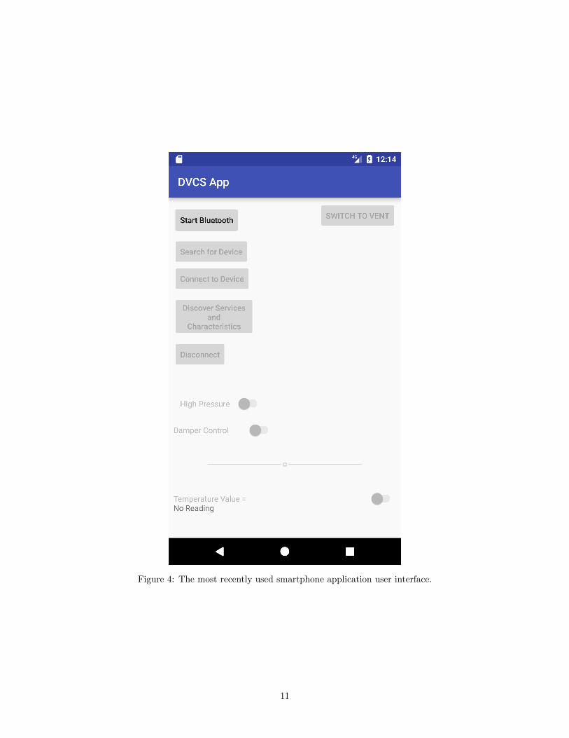
Figure 4: The most recently used smartphone application user interface.
11
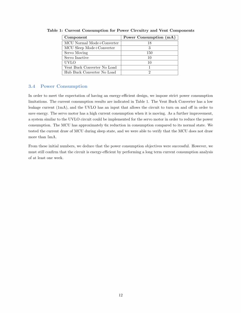
Table 1: Current Consumption for Power Circuitry and Vent Components
Component Power Consumption (mA)
MCU Normal Mode+Converter 18MCU Sleep Mode+Converter 3Servo Moving 150Servo Inactive 10UVLO 10Vent Buck Converter No Load 1Hub Buck Converter No Load 2
3.4 Power Consumption
In order to meet the expectation of having an energy-efficient design, we impose strict power consumption
limitations. The current consumption results are indicated in Table 1. The Vent Buck Converter has a low
leakage current (1mA), and the UVLO has an input that allows the circuit to turn on and off in order to
save energy. The servo motor has a high current consumption when it is moving. As a further improvement,
a system similar to the UVLO circuit could be implemented for the servo motor in order to reduce the power
consumption. The MCU has approximately 6x reduction in consumption compared to its normal state. We
tested the current draw of MCU during sleep state, and we were able to verify that the MCU does not draw
more than 5mA.
From these initial numbers, we deduce that the power consumption objectives were successful. However, we
must still confirm that the circuit is energy-efficient by performing a long term current consumption analysis
of at least one week.
12

4 Cost
4.1 Parts
Table 2: Parts Costs
Part Manufacturer Retail Cost
($)
Bulk
Purchase
Cost ($)
AC-DC Converter (WSU120-1000) Triad Magnetics 10.94 8.16
Temperature Sensor (MAX31820MCR+) Maxim Integrated 1.30 1.18
Hub MCU (CY8C4248LQI-BL583) Cypress Semiconductor 14.96 8.38
Vent MCU (CYBL11573-56LQXI) Cypress Semiconductor 15.75 9.98
PWM (TL5001AQDRQ1) Texas Instruments 2.09 1.02
Pressure Sensor (BMP180) Bosch Sensortec 9.95 9.95
Servo Motor (HS-311) Hitec 7.89 7.42
4 AA Lithium Batteries Energizer 7.78 5.94
Misc RLC and Diodes ∼6.00 ∼6.00
Misc Physical Components ∼6.00 ∼6.00
Shipping and Taxes ∼15.00 ∼15.00
Total 97.66 79.03
4.2 Labor
• $40/hr per person (3 total)
• 185 hours spent per person (3 total)
• Total Labor Cost = $22,200
4.3 Grand Total
Grand Total = Total Part Cost + Total Labor Cost = $22,297.66
13

5 Conclusion
5.1 Accomplishments
In one semester, we successfully controlled a register damper wirelessly. We spent the majority of the time
programming and debugging the MCUs so that communication via BLE was properly engaged. Similarly,
we divided the other portion of the time testing the power circuitry. As a result, we were able to design a
power-efficient circuit.
5.2 Uncertainties
We lacked proper integration of individual units, and this occurred for a few reasons. The first was that some
of the components in our DC-DC converters failed. Another is that the communication interface between
the Vent and Hub MCUs was not established properly in firmware, so we resorted to using the smartphone
as a mediator between both MCUs.
In addition, although we were able to record current consumption across multiple components, we did not
test over a long duration. The long term analysis exhibits a better representation of ideal battery life in the
design.
5.3 Future Work and Alternatives
In order to continue work on this project, we highlight a few key steps to follow:
• Redesign the Vent register. The machine shop built a functional opening and closing mechanism by
appending to an existing store-bought register. However, we can reduce the torque required by the
servo motor if the dampers themselves are a custom design. Similarly, we can improve the aesthetics
in this manner.
• Test power consumption over a period of at least a week. Analyzing these results evaluate both circuit
stability as well as overall efficiency of the design.
• Control multiple Vent Units simultaneously. In our current revision, communication is only to a single
Vent Unit, and this may not work for larger rooms.
• Improve smartphone application. The version used in our final demonstration includes many unnec-
essary buttons, and the alert system for low batteries or high pressure is not functional. Cleaning up
both of these aspects should be feasible.
5.4 Safety
Since this product operates on electricity, there is always a chance for fires. There is a serious risk of injury or
death if the user mis-uses the electrical components, especially ones directly connected to the power source
[15]. This product must remain dry in order to avoid any chance of malfunction caused by a short circuit.
One of the largest concerns by closing dampers within a HVAC system is the increased pressure within the
ducts, causing potential breakdown if the pressure exceeds 0.75” WC, or 0.187 kPA[16, 10]. It is critical
to relay to the consumer that dampers should not be shut off manually, for the pressure sensor within the
14

Vent Unit will be able to automatically detect the static pressure and prevent the aforementioned hazard by
opening the dampers accordingly. In the case that the batteries are low, the damper state could potentially
be closed. Our UVLO is designed to handle this hazard.
5.5 Ethical Considerations
All members of our team must comply to the latest iteration of the IEEE Code of Ethics[17]. One of the
important points on this list for our design is 3, that is to be honest and realistic in stating claims or estimates
based on available data. When we identify the power consumption of our circuit, we cannot create any false
statistics that suggest an unusually long battery life if that is not truly the case. Another emphasis is placed
on 7, which is to seek, accept, and offer honest criticism of technical work, to acknowledge and correct errors,
and to credit properly the contributions of others. As members of the University of Illinois, we must adhere
to all class policies regarding plagiarism and we should strictly cite any external resources.
Points 8, 9, and 10 are related to group interactions, and since this project is worked on as a group, it is
important to remind ourselves that we must create an atmosphere where we respect one another. As painfully
simple as it may seem, conflicts do arise, and it is best to resolve any such issues in a professional manner.
Examples of potential conflicts include irregular distribution of work and disagreement on implementation
decisions. Engagement of the course staff will be required if more serious issues arise.
The rest of the points in the Code of Ethics should be adhered to, however, either we do not need to put
much emphasis on them or their importance is already covered in this proposal (1). General training (6)
is covered through lab safety seminars online. We do not see any potential conflicts of interests (2), nor
do we expect any form of bribery to occur (4). As students, it is assumed that 5, which is to improve the
understanding of technology, its appropriate application, and potential consequences, is constantly being
adhered to.
15

References
[1] “Windows and heat loss,” 2016. [Online]. Available: https://www.e-education.psu.edu/egee102/node/
2017
[2] E. Systems, “Ecovent.” [Online]. Available: https://www.ecoventsystems.com/
[3] K. H. Inc, “Keen home,” 2016. [Online]. Available: http://keenhome.io
[4] E. Systems, “Ecovent.” [Online]. Available: https://ecoventsystems.com/faq
[5] “Keen home smart vent review.” [Online]. Available: https://www.amazon.com/
Keen-Home-Smart-Vent-x10/product-reviews/B00YCAWCV4/ref=cm cr arp d viewopt srt?
ie=UTF8&reviewerType=avp only reviews&sortBy=recent&pageNumber=1
[6] ecobee, “Smart wifi thermostats by ecobee,” 2017. [Online]. Available: https://www.ecobee.com/
[7] N. Labs, “Meet the nest learning thermostat,” 2017. [Online]. Available: https://nest.com/thermostat/
meet-nest-thermostat/
[8] “Specification of the bluetooth system,” 2016.
[9] M. T. Inc, “Bluetooth smart communication using microchip rn4020,” 2014. [Online]. Available:
http://ww1.microchip.com/downloads/en/AppNotes/00001861A.pdf
[10] “A simple way to explain static pressure.” [Online]. Available: http://ncidavid.blogspot.com/2013/04/
a-simple-way-to-explain-static-pressure.html
[11] “Noise comparisons.” [Online]. Available: https://www.chem.purdue.edu/chemsafety/Training/
PPETrain/dblevels.htm
[12] “Tl5001a pulse-width-modulation control circuits,” 1994. [Online]. Available: http://www.ti.com/lit/
ds/symlink/tl5001.pdf
[13] “Designing with the tl5001 pwm controller,” 1995. [Online]. Available: http://www.ti.com/lit/an/
slva034a/slva034a.pdf
[14] “Psoc video tutorial series: How to create android apps to inter-
act with cypress ble.” [Online]. Available: http://www.cypress.com/training/
psoc-video-tutorial-series-how-create-android-apps-interact-cypress-ble
[15] “Risk assessment: Use of standard electrical equipment.” [Online]. Available: https://www.chemie.
uni-kl.de/fileadmin/chemie/Dokumente/Dokumente BC/Sicherheit/GA/RAElectrical.pdf
[16] Q. H. Maintenance, “Why closing air vents in unused rooms damages your
heating/cooling system,” 2015. [Online]. Available: http://georgebrazilhvac.com/blog/
why-closing-air-vents-in-unused-rooms-damages-your-heating-cooling-system
[17] “Ieee code of ethics 2017,” 2017. [Online]. Available: http://www.ieee.org/about/corporate/
governance/p7-8.html
16
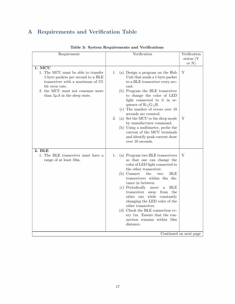
A Requirements and Verification Table
Table 3: System Requirements and Verifications
Requirement Verification Verificationstatus (Y
or N)1. MCU
1. The MCU must be able to transfer1-byte packets per second to a BLEtransceiver with a maximum of 5%bit error rate.
2. the MCU must not consume morethan 5µA in the sleep state.
1. (a) Design a program on the HubUnit that sends a 1-byte packetto a BLE transceiver every sec-ond.
(b) Program the BLE transceiverto change the color of LEDlight connected to it in se-quence of R-¿G-¿B.
(c) The number of errors over 10seconds are counted.
2. (a) Set the MCU to the sleep modeby manufacturer command.
(b) Using a multimeter, probe thecurrent of the MCU terminalsand identify peak current drawover 10 seconds.
Y
Y
2. BLE1. The BLE transceiver must have a
range of at least 10m.1. (a) Program two BLE transceivers
so that one can change thecolor of LED light connected tothe other transceiver.
(b) Connect the two BLEtransceivers within 0m dis-tance in between.
(c) Periodically move a BLEtransceiver away from theother one while constantlychanging the LED color of theother transceiver.
(d) Check the BLE connection ev-ery 1m. Ensure that the con-nection remains within 10mdistance.
Y
Continued on next page
17

Table 3 – continued from previous pageRequirement Verification Verification
status (Yor N)
3. Voltage Regulator1. The Voltage Regulator must ensure
all components are provided with3.3V (+/- 15%).
2. The Voltage Regulator must drawno more than 1 A (+/- 20%).
1. (a) Provide a constant voltageload (5V) as an input to theregulator.
(b) Measure the voltage acrossoutput and compare to speci-fied target threshold.
2. (a) Provide a constant voltage(5V) load as an input to theregulator.
(b) Measure current draw acrossinput/output terminals of reg-ulator using multimeter over aperiod of 60 seconds.
(c) Analyze peak current in timewindow and compare to speci-fied upper limit.
Y
Y
4. Undervoltage Lockout1. The current draw of this module
must be minimum 0A and maxi-mum 20mA.
1. (a) Sweep a load voltage from2.5V to 3.3V in 0.1V incre-ments.
(b) Use a multimeter to measurethe terminals and ensure thecurrent draw is within thespecified limit.
Y
5. Temperature Sensor1. The temperature sensor must be ac-
curate by +/- 0.5 C.1. (a) Program the MCU to read and
print the temperature readingevery second to the terminalthrough UART.
(b) Measure the temperature ofthe sensor surface with a tem-perature meter .
(c) Compare the printed value onthe terminal and the tempera-ture meter value.
(d) Ensure that the sensor’s valueis accurate to 0.5 C.
Y
Continued on next page
18

Table 3 – continued from previous pageRequirement Verification Verification
status (Yor N)
6. Pressure Sensor1. The pressure sensor must be accu-
rate to +/- 0.01 kPa.1. (a) In a closed room, measure the
air pressure with a pressuremeter for 10 seconds.
(b) Record the readings from theVent Unit’s pressure sensor forthe same duration.
(c) Compare the differences andidentify worst-case error. Thiserror cannot exceed the speci-fied error tolerance.
N
7. Servo Motor1. The servo motor must have quiet
operation under 40 dB (+/- 15%).2. The servo motor must output an ad-
equate 1 lb/in (+/- 10%) of torque.
1. (a) Use a decibel meter to recordthe sound level of the servomotor.
(b) Sweep speeds of servo motorfrom minimum to maximumRPM and ensure sound level ismet.
2. (a) Probe servo motor using atorque meter and sweep speedsof servo motor.
(b) Identify speed at which torquefalls within error margin.
Y
Y
19

B Physical Design Rendering
Figure 5: Initial designs of Vent Unit combined with register.
20

C Schematics
Figure 6: UVLO schematic.
21

Figure 7: Hub Unit DC-DC converter schematic.
Figure 8: Vent Unit DC-DC converter schematic.
22

D Simulations
Figure 9: A simple buck converter schematic used for simulation.
23

Figure 10: IL and Vout for Iout at 0.5 A.
24

Figure 11: IL and Vout for Iout at 3 A.
25