e cient closed-loop detection and pose estimation for
TRANSCRIPT
Efficient Closed-Loop Detection and Pose Estimation
for Vision-Only Relative Localization in Space with A
Cooperative Target
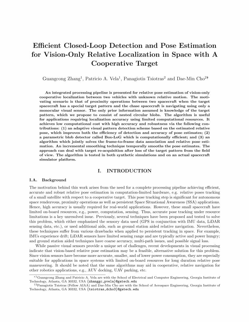
Guangcong Zhang1, Patricio A. Vela1, Panagiotis Tsiotras2 and Dae-Min Cho2∗†
An integrated processing pipeline is presented for relative pose estimation of vision-onlycooperative localization between two vehicles with unknown relative motion. The moti-vating scenario is that of proximity operations between two spacecraft when the targetspacecraft has a special target pattern and the chase spacecraft is navigating using only amonocular visual sensor. The only prior information assumed is knowledge of the targetpattern, which we propose to consist of nested circular blobs. The algorithm is usefulfor applications requiring localization accuracy using limited computational resources. Itachieves low computational cost with high accuracy and robustness via the following con-tributions: (1) an adaptive visual pattern detection scheme based on the estimated relativepose, which improves both the efficiency of detection and accuracy of pose estimates; (2)a parametric blob detector called Box-LoG which is computationally efficient; and (3) analgorithm which jointly solves the frame-to-frame data association and relative pose esti-mation. An incremental smoothing technique temporally smooths the pose estimates. Theapproach can deal with target re-acquisition after loss of the target pattern from the fieldof view. The algorithm is tested in both synthetic simulations and on an actual spacecraftsimulator platform.
I. INTRODUCTION
I.A. Background
The motivation behind this work arises from the need for a complete processing pipeline achieving efficient,accurate and robust relative pose estimation in computation-limited hardware, e.g. relative poses trackingof a small satellite with respect to a cooperative target. This pose tracking step is significant for autonomousspace rendezvous, proximity operations as well as persistent Space Situational Awareness (SSA) applications.Hence, high accuracy is usually required for real-world applications. However, these small spacecraft havelimited on-board resources, e.g., power, computation, sensing. Thus, accurate pose tracking under resourcelimitations is a key unresolved issue. Previously, several techniques have been proposed and tested to solvethis problem, which either emphasized the sensory data used (GPS in conjunction with IMU data, LiDARsensing data, etc.), or used additional aids, such as ground station aided relative navigation. Nevertheless,these techniques suffer from various drawbacks when applied to persistent tracking in space. For example,IMUs experience drift; LiDAR sensors have limited sensing range and are typically active and power hungry;and ground station aided techniques have coarse accuracy, multi-path issues, and possible signal loss.
While passive visual sensors provide a unique set of challenges, recent developments in visual processingindicate that vision-based relative pose estimation may be a feasible, alternative solution for this problem.Since vision sensors have become more accurate, smaller, and of lower power consumption, they are especiallysuitable for applications in space systems with limited on-board resources for long duration relative posemaneuvering. It should be noted that the same algorithms may aid in cooperative, relative navigation forother robotics applications, e.g., AUV docking, UAV parking, etc.
∗1Guangcong Zhang and Patricio A. Vela are with the School of Electrical and Computer Engineering, Georgia Institute ofTechnology, Atlanta, GA 30332, USA {zhanggc,pvela}@gatech.edu†2Panagiotis Tsiotras (Fellow AIAA) and Dae-Min Cho are with the School of Aerospace Engineering, Georgia Institute of
Technology, Atlanta, GA 30332, USA {tsiotras,dcho3}@gatech.edu
Problem. In the cooperative satellite proximity operations scenario, the objective is to achieve vision-based, relative navigation about a target satellite via a known pattern placed on the target satellite. Relativenavigation should be precise when the known pattern is in view. However, since the pattern may come inand out of the field of view depending on the maneuvers performed by the tracking satellite, the systemmust be capable of detecting and locking onto the pattern throughout the engagement scenario, as well asrecognizing when the pattern has been lost. Due to resource constraints, the processing pipeline shouldbe as computationally efficient as possible, while being robust to uncertainty in the measurements and theuncontrolled relative geometry.
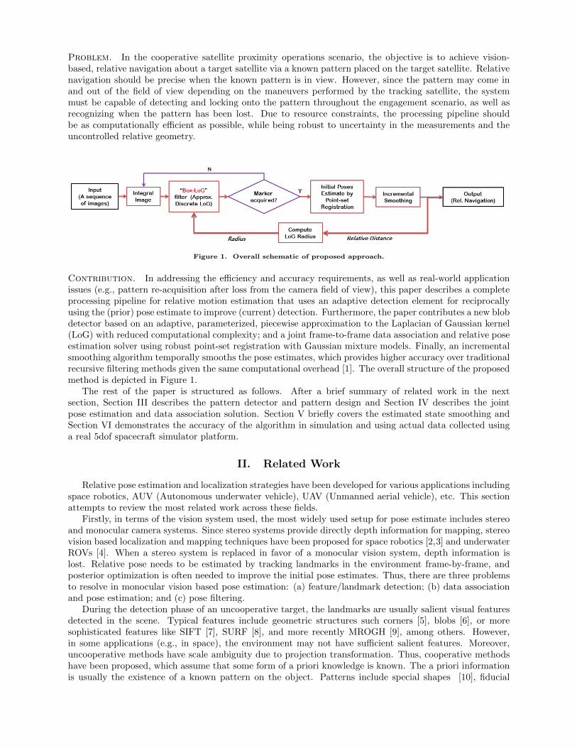
Figure 1. Overall schematic of proposed approach.
Contribution. In addressing the efficiency and accuracy requirements, as well as real-world applicationissues (e.g., pattern re-acquisition after loss from the camera field of view), this paper describes a completeprocessing pipeline for relative motion estimation that uses an adaptive detection element for reciprocallyusing the (prior) pose estimate to improve (current) detection. Furthermore, the paper contributes a new blobdetector based on an adaptive, parameterized, piecewise approximation to the Laplacian of Gaussian kernel(LoG) with reduced computational complexity; and a joint frame-to-frame data association and relative poseestimation solver using robust point-set registration with Gaussian mixture models. Finally, an incrementalsmoothing algorithm temporally smooths the pose estimates, which provides higher accuracy over traditionalrecursive filtering methods given the same computational overhead [1]. The overall structure of the proposedmethod is depicted in Figure 1.
The rest of the paper is structured as follows. After a brief summary of related work in the nextsection, Section III describes the pattern detector and pattern design and Section IV describes the jointpose estimation and data association solution. Section V briefly covers the estimated state smoothing andSection VI demonstrates the accuracy of the algorithm in simulation and using actual data collected usinga real 5dof spacecraft simulator platform.
II. Related Work
Relative pose estimation and localization strategies have been developed for various applications includingspace robotics, AUV (Autonomous underwater vehicle), UAV (Unmanned aerial vehicle), etc. This sectionattempts to review the most related work across these fields.
Firstly, in terms of the vision system used, the most widely used setup for pose estimate includes stereoand monocular camera systems. Since stereo systems provide directly depth information for mapping, stereovision based localization and mapping techniques have been proposed for space robotics [2,3] and underwaterROVs [4]. When a stereo system is replaced in favor of a monocular vision system, depth information islost. Relative pose needs to be estimated by tracking landmarks in the environment frame-by-frame, andposterior optimization is often needed to improve the initial pose estimates. Thus, there are three problemsto resolve in monocular vision based pose estimation: (a) feature/landmark detection; (b) data associationand pose estimation; and (c) pose filtering.
During the detection phase of an uncooperative target, the landmarks are usually salient visual featuresdetected in the scene. Typical features include geometric structures such corners [5], blobs [6], or moresophisticated features like SIFT [7], SURF [8], and more recently MROGH [9], among others. However,in some applications (e.g., in space), the environment may not have sufficient salient features. Moreover,uncooperative methods have scale ambiguity due to projection transformation. Thus, cooperative methodshave been proposed, which assume that some form of a priori knowledge is known. The a priori informationis usually the existence of a known pattern on the object. Patterns include special shapes [10], fiducial

markers [11], or specially designed patterns such as self-similar landmarks [12], Haar rectangular features [13],2D bar code style pattern [14], and rings structures [15], etc. Detection of some of these patterns is eithercomputational costly [12], are not robust to large scale changes [10,11,14,15], or they cannot provide accurate6dof pose estimation [13].
Regarding the data association and pose estimation steps, pose estimation with corresponding featuresis widely considered a solved problem [16]. It is the data association that remains the key problem. Conven-tionally, data association is solved by matching the feature descriptors under some mapping criterion [17]or within a robust statistic framework such as RANSAC [18]. However, these techniques rely on the dis-tinctiveness of features. For data association without distinct features, some techniques have been proposedbased on point-set matching [11, 19] or image registration [20]. These techniques are especially useful forcooperative cases in which the features from the marker pattern are all similar, such as fiducial dots.
The pose estimates derived from consecutive frames usually suffer from errors. These errors can bereduced through posterior estimation via minimization of the image re-projection errors. Most of the lit-erature for relative pose estimation employs recursive filtering to improve the pose estimates. Popularfiltering methods include EKF [21], Particle Filters [22, 23], and their numerous variants [19, 24]. However,recent developments in computer vision demonstrate that (keyframe) batch optimization techniques are moreadvantageous than filtering-based techniques because the former provides more accuracy per unit of com-puting time [1]. Smoothing techniques fall under the batch optimization paradigm; incremental smoothingtechniques, which are advantageous over traditional fixed-lag/fixed-interval smoothing, have also been devel-oped [25,26], enabling efficient frame-wise smoothing. For space applications only recently has the smoothingframework been used. For example, [11] uses fix-lag smoothing. However, though incremental smoothinghas been used for underwater odometry applications [27], it has not been applied to space applications.
Typically, each component in the monocular vision-based relative pose estimation pipeline operates inan open-loop fashion, with one output feeding on to the next input. There is no feedback of informationfrom a later stage to an earlier stage. Our work includes an information feedback loop, whereby the poseestimates are fed back to the detection step to improve the target pattern detection reliability, which thenimpacts future pose estimates.
III. Pattern Detector and Target Pattern Choices
In the scenario considered in this work, pattern detection needs to be invariant to relative orientationabout the optical axis, insensitive to the distance from target, and somewhat robust to the perspectivedistortion caused by angled views of the pattern. Furthermore, the pattern should provide sufficient infor-mation to estimate relative pose. The simplest pattern element that fits these constraints, while leadingto an equally simple detection algorithm is a blob (a filled circle). This section details a computationallyefficient blob detector and describes a pattern, consisting of blob pattern elements, that works at multiplescales (and hence multiple orders of distance).
III.A. Efficient, Adaptive Detection with the Box-LoG Kernel
An optimal parametric detector for blob-like structures across multiple scales is the normalized Laplacian ofGaussian (LoG) detector [6], which applies a normalized and smoothed Laplacian operator 4 to a 2D field:
4G = σ2
(∂2G
∂x2+∂2G
∂y2
)=x2 + y2 − 2σ2
2πσ4e−
(x2+y2)
2σ2 , (1)
where σ is a function of the blob radius r to detect, σ = r/√
2. For an image I, the operation involves a 2Ddiscrete convolution with the LoG kernel f(x, y), where x, y ∈ [−RLoG, RLoG] ⊂ Z and RLoG = d3σe+ 1 toavoid shift artifacts. Appropriately sized blobs in an image I give large magnitude values in the convolvedimage I ∗ f .
In [6], two blob detectors with similar properties were analyzed, the trace of the Hessian (same as Eq.(1)) and the determinant of the Hessian of second order derivatives. The SURF descriptor [8] employsapproximations to the determinant of the Hessian by piecewise constant discrete derivatives to achieveefficient operation. However, a piecewise constant trace approximation will have an even lower computationalcost with marginal difference in the output.
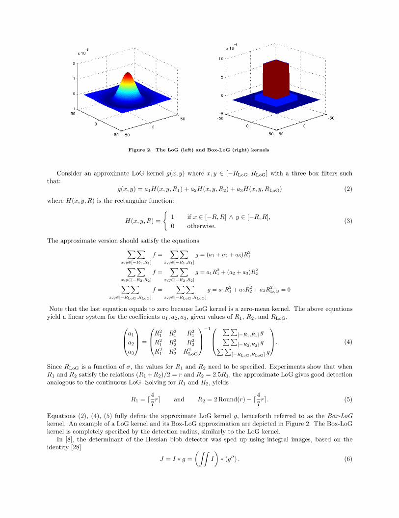
Figure 2. The LoG (left) and Box-LoG (right) kernels
Consider an approximate LoG kernel g(x, y) where x, y ∈ [−RLoG, RLoG] with a three box filters suchthat:
g(x, y) = a1H(x, y,R1) + a2H(x, y,R2) + a3H(x, y,RLoG) (2)
where H(x, y,R) is the rectangular function:
H(x, y,R) =
{1 if x ∈ [−R,R] ∧ y ∈ [−R,R],
0 otherwise.(3)
The approximate version should satisfy the equations∑∑x,y∈[−R1,R1]
f =∑∑
x,y∈[−R1,R1]
g = (a1 + a2 + a3)R21∑∑
x,y∈[−R2,R2]
f =∑∑
x,y∈[−R2,R2]
g = a1R21 + (a2 + a3)R
22∑∑
x,y∈[−RLoG,RLoG]
f =∑∑
x,y∈[−RLoG,RLoG]
g = a1R21 + a2R
22 + a3R
2LoG = 0
Note that the last equation equals to zero because LoG kernel is a zero-mean kernel. The above equationsyield a linear system for the coefficients a1, a2, a3, given values of R1, R2, and RLoG,a1
a2
a3
=
R21 R2
1 R21
R21 R2
2 R22
R21 R2
2 R2LoG
−1
∑∑[−R1,R1] g∑∑[−R2,R2] g∑∑
[−RLoG,RLoG] g
. (4)
Since RLoG is a function of σ, the values for R1 and R2 need to be specified. Experiments show that whenR1 and R2 satisfy the relations (R1 +R2)/2 = r and R2 = 2.5R1, the approximate LoG gives good detectionanalogous to the continuous LoG. Solving for R1 and R2, yields
R1 = d47re and R2 = 2 Round(r)− d4
7re. (5)
Equations (2), (4), (5) fully define the approximate LoG kernel g, henceforth referred to as the Box-LoGkernel. An example of a LoG kernel and its Box-LoG approximation are depicted in Figure 2. The Box-LoGkernel is completely specified by the detection radius, similarly to the LoG kernel.
In [8], the determinant of the Hessian blob detector was sped up using integral images, based on theidentity [28]
J = I ∗ g =
(∫∫I
)∗ (g′′) . (6)
The Box-LoG operation benefits from the same property. Since computing the trace is a simpler operationthan computing the determinant and, in addition, it does not require the mixed second order derivatives,there will be fewer evaluations of the integral image compared to [8]. The discrete version of the integralimage is defined to be:
Iint(x, y) =∑
x′≤x,y′≤y
I(x′, y′). (7)
The second derivative of Box-LoG consists of a linear combination of eight Dirac delta functions, leading toeight evaluations of Iint for the discrete version of J ,
J(x, y) =
1∑i=0
1∑j=0
(−1)i+j(a1 − a2) · Iint(x+ (−1)iR1 , y + (−1)jR1
)+ (−1)i+j(a2 − a3) · Iint
(x+ (−1)iR2 , y + (−1)jR2
).
Given Iint, computing J involves simple products and sums that take constant runtime. After computingthe response image J across a discrete quantity of radius scales (octaves in the computer vision parlance),the blob detection process then thresholds the response magnitudes followed by non-maximum suppression(dark blobs give positive extrema and light blobs give negative extrema). Using circular blobs as patternelements gives rotational invariance about the optical axis and some insensitivity to view-point deviationsfrom the optical axis.
Distance Adaptive Scale Selection. The image formed by a circular marker as seen through a cameradepends on the intrinsic camera parameters, the marker’s world radius, and the camera to marker distance.For the marker’s image radius, there is a direct linear relationship with its world radius and an inverserelationship with the camera-to-marker distance.
During an engagement scenario, this information can be exploited, when it is known. Thus, as part of theprocessing pipeline, the Box-LoG kernel radius parameter is adapted via feedback of the estimated targetposition from the previous frame (lower box of Figure 1), as follows
rk+1 =λ√
x2k + y2
k + z2k
, (8)
where λ is a constant determined by the target marker’s world radius (a known constant) and the intrinsiccamera parameters, (xk, yk, zk) is the relative position of the camera with respect to the target center in thek-th frame, and rk+1 is the detection radius estimate for the (k + 1)-th frame.
III.B. Landmark Pattern
Given that the pattern consists of circularly symmetric pattern elements (e.g., blobs), whose detection pa-rameters depend on the camera-to-target distance, a pattern is needed that fulfills the remaining constraints.Converting the remaining expectations into a list of features gives:
i) pattern elements at multiple scales, for robustness to scale changes;
ii) co-planarity, for rapid pose estimation through homographic geometry;
iii) sufficient pattern elements in quantity, for well-posed pose estimation; and
iv) an asymmetric and non-collinear topology, to avoid degeneracy in pose estimation and pose ambiguitydue to rotations or perspective foreshortening.
A pattern element or marker that achieves the first feature is depicted in Figure 3. The marker consistsof nested blobs at different scales and complementary contrasts (dark on light vs. light on dark). The circleradius at one blob size is 4.5 times greater than that of the next nested smaller size. The factor ensuresthat the nested blobs can be arranged such that a properly adapted Box-LoG filter centers exactly on ablob without getting response interference from a neighboring blob nor from a neighboring blob scale (thelarger blob). When combined with the multi-scale blob detector from Section III.A, the blobs at a givenscale can be robustly tracked until the next scale is identified (about two octaves later and with the opposite
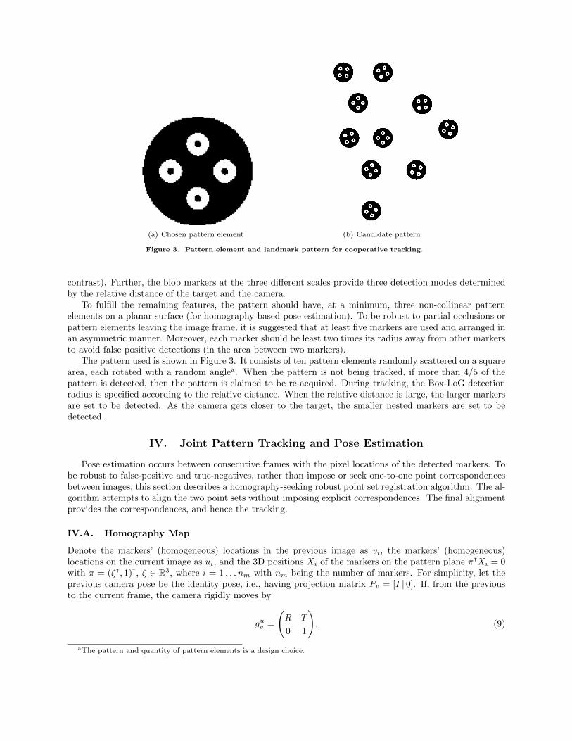
(a) Chosen pattern element (b) Candidate pattern
Figure 3. Pattern element and landmark pattern for cooperative tracking.
contrast). Further, the blob markers at the three different scales provide three detection modes determinedby the relative distance of the target and the camera.
To fulfill the remaining features, the pattern should have, at a minimum, three non-collinear patternelements on a planar surface (for homography-based pose estimation). To be robust to partial occlusions orpattern elements leaving the image frame, it is suggested that at least five markers are used and arranged inan asymmetric manner. Moreover, each marker should be least two times its radius away from other markersto avoid false positive detections (in the area between two markers).
The pattern used is shown in Figure 3. It consists of ten pattern elements randomly scattered on a squarearea, each rotated with a random anglea. When the pattern is not being tracked, if more than 4/5 of thepattern is detected, then the pattern is claimed to be re-acquired. During tracking, the Box-LoG detectionradius is specified according to the relative distance. When the relative distance is large, the larger markersare set to be detected. As the camera gets closer to the target, the smaller nested markers are set to bedetected.
IV. Joint Pattern Tracking and Pose Estimation
Pose estimation occurs between consecutive frames with the pixel locations of the detected markers. Tobe robust to false-positive and true-negatives, rather than impose or seek one-to-one point correspondencesbetween images, this section describes a homography-seeking robust point set registration algorithm. The al-gorithm attempts to align the two point sets without imposing explicit correspondences. The final alignmentprovides the correspondences, and hence the tracking.
IV.A. Homography Map
Denote the markers’ (homogeneous) locations in the previous image as vi, the markers’ (homogeneous)locations on the current image as ui, and the 3D positions Xi of the markers on the pattern plane πTXi = 0with π = (ζT, 1)T, ζ ∈ R3, where i = 1 . . . nm with nm being the number of markers. For simplicity, let theprevious camera pose be the identity pose, i.e., having projection matrix Pv = [I | 0]. If, from the previousto the current frame, the camera rigidly moves by
guv =
(R T
0 1
), (9)
aThe pattern and quantity of pattern elements is a design choice.
then the camera projection on the current frame is
Pu = [R |T ]. (10)
Since the two views are of points in the same plane, a homography map relates corresponding points betweenconsecutive frames (i.e., it maps vi to ui) [16]. The homography map depends on the transformation andthe plane normal vector as follows
H = (R− TζT). (11)
If the point correspondences are known, then the homography, and ultimately the transformation matrixguν , is computable [16]. Alternatively, if the homography is known, then the points can be placed intocorrespondence and tracked. The problem arises when neither are known, and the point sets have extra ormissing elements (due to false positive or true negatives). To handle these uncertainties, the next sectionjointly solves the pose estimation and point tracking problems using robust point-set registration.
IV.B. Robust Point-Set Registration
In robust point-set registration, each image point set {ui} and {νj} of potentially different cardinalitygenerates a Gaussian Mixture Model (GMM), the first of which is also parameterized by the unknownhomography map H. Point-set registration is performed by minimizing the L2 distance of the GMMs [29,30].Normally the minimization is performed over the space of rigid or affine transformations (plus possibly aparameterized model of non-affine deformations), however in this work the minimization is performed overthe space of homographic maps.
The GMM generator for a set of points x = {xi}|x|i=1 is
Φ (x ; x) =1
|x|
|x|∑i=1
N (x ; xi,Σ), (12)
where |x| is the cardinality of the set x, N (· ; ·, ·) is the multi-variate normal distribution (the secondargument is the mean and the third is the covariance), and Σ is a constant covariance matrix (here, adiagonal matrix with equal variances). The homography map parameterized by the GMM generator is
Φ (x ; x, H) =1
|x|
|x|∑i=1
N (x ; Axi + b, AΣAT), (13)
given that the homography map of an image point x ∈ R2 is H(x) = Ax + b. Given two points sets u andv, and a homography map H, the registration error defined by the L2 distance of the generated GMMs is
dist(Φ (· ; u, H) ,Φ (· ; v)) ,∫
(Φ (x ; u, H)− Φ (x ; v))2 dx
The multi-variate Gaussian distribution obeys the identity∫N (x ; µ1,Σ1)N (x ; µ2,Σ2) dx = N (0 ; µ1 − µ2,Σ1 + Σ2).
As a result, dist(Φ (· ; u, H) ,Φ (· ; v)) can be computed in closed-form as follows
dist(Φ (· ; u, H) ,Φ (· ; v)) =1
|u|2|u|∑i=1
|u|∑j=1
N (0 ; A(ui − uj), 2AΣAT)
+1
|v|2|u|∑i=1
|v|∑j=1
N (0 ; νi − νj , 2Σ)
−21
|u||v|
|u|∑i=1
|v|∑j=1
N (0 ; H(ui)− νj , AΣAT + Σ).

Minimization of the distance is performed iteratively through gradient descent. The first two terms areconstant, having no effect on the optimization, and thus they do not factor into the iterations. The SE(3)transformation is then recovered by minimizing dist(Φ (· ; u, H) ,Φ (· ; v)) over H,
H = arg minH
dist(Φ (· ; u, H) ,Φ (· ; v))
= arg maxH
1
|u||v|
|u|∑i=1
|v|∑j=1
N (0 ; H(ui)− νj , AΣAT + Σ).
After finding H, two points ui and νj are considered to be in correspondence if they have minimal distancecompared to all other possible correspondences, and the minimizing distance is below a threshold. Thetransformation guν in (9) is determined using the matrix entries of H given ζ [16].
V. Smoothing the Pose Estimates
While the pose estimates are optimized for the current observations conditioned on the previous obser-vations (Section IV.B), they are not optimized temporally over all observations (e.g., they are not filtered).For vision-based measurements, temporal filtering is performed by minimizing the image re-projection errorsgiven the set of pose estimates and homographic mappings to date.
Denote by G , {gτ} the set of camera poses at time instants τ , by L , {lj} the constant set of
target pattern landmarks where j ranges over all possible landmark indices, by Z , {ζτ} the collection ofmeasurements where ζτ consists of the points {ui} that were imaged at time τ (when indicating the timeinstant, we will write ui,τ , In addition, there is a time-dependent association function ατ (·) that matchesa measurement index to a landmark index (this function is instantiated when the pattern is detected andmaintained during marker tracking). Define the measurement function h(g, l) to be the perspective cameraprojection mapping 3D points to 2D image coordinates. Given a measurement and landmark association,the image re-projection error for measurement index i at time τ is:
εi,τ = h(gτ , lατ (i))− ui,τ . (14)
Assuming Gaussian measurement noise, the distribution of the measurement given the landmark positionsis
P(ui,τ |gτ , lατ (i)
)∝ exp
(−1
2‖εi,τ‖2Σk
). (15)
Define Θ , (G,L) as the collection of the unknown camera poses and landmarks, and model the systemwith a factor graph. In our case, no odometry information is available, therefore the factors that encode theprediction model do not exist. Using the factorization property of factor graphs, the joint probability of allrandom variables is
P (Θ) ∝
(∏τ
ϕτ (θτ )
)∏τ,j
ψτ,j(θτ , θj)
, (16)
where τ ranges over the variables in G, j ranges over the variables in L, the potentials ϕτ (θτ ) encode a priorestimate at θτ ∈ Θ, and the pairwise potentials ψτ,j(θτ , θj) encode information between two factors (here, acamera pose and a landmark). Using this information, the potentials are
ϕτ (θτ ) ∝ P (gτ ) (17)
ψτ,j(θτ , θj) ∝ P (uα−1τ (j),τ |gτ , lj). (18)
For the second set of potentials, the potential (and hence factor graph edge) does not exist when the inverseis not defined for a given (τ, j) (i.e., the landmark was not seen). The maximum a posteriori (MAP) estimateis
Θ = arg maxΘ
P (X,L|Z) = arg maxΘ
P (X,L,Z),
= arg minΘ
(− logP (Θ)).
Since the information is arriving in time, the incremental smoothing method [25, 26] is used for optimizingthe pose estimates. We use the GTSAM library, written by the authors of the above references, to implementthe incremental smoothing step.
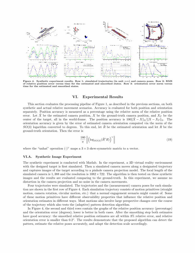
Figure 4. Synthetic experiment results. Row 1: simulated trajectories (in unit mm) and camera poses. Row 2: RMSof relative position error versus time for the estimated and smoothed states. Row 3: orientation error norm versustime for the estimated and smoothed states.
VI. Experimental Results
This section evaluates the processing pipeline of Figure 1, as described in the previous sections, on bothsynthetic and actual relative movement scenarios. Accuracy is evaluated for both position and orientationseparately. Position accuracy is measured as a percentage using the relative norm of the relative positionerror. Let X be the estimated camera position, X be the ground-truth camera position, and XT be thecenter of the target, all in the world-frame. The position accuracy is 100‖X −X‖2/‖X −XT ‖2. Theorientation accuracy is given by the error of estimated camera orientation computed via the norm of theSO(3) logarithm converted to degrees. To this end, let R be the estimated orientation and let R be theground-truth orientation. Then the error is
180
π
∥∥∥∥(logSO(3)(RTR))∨∥∥∥∥ (19)
where the “unhat” operation (·)∨ maps a 3× 3 skew-symmetric matrix to a vector.
VI.A. Synthetic Image Experiment
The synthetic experiment is conducted with Matlab. In the experiment, a 3D virtual reality environmentwith the designed target is first simulated. Then a simulated camera moves along a designated trajectoryand captures images of the target according to a pinhole camera projection model. The focal length of thesimulated camera is 1, 388 and the resolution is 1082× 722. The algorithm is then tested on these syntheticimages and the results are evaluated comparing to the ground-truth. In this experiment, we assume nodistortion in the camera projection and no noise in the camera movements.
Four trajectories were simulated. The trajectories and the (measurement) camera poses for each simula-tion are shown in the first row of Figure 4. Each simulation trajectory consists of motion primitives (straightmotion, camera rotation, circular motion, etc.) that a normal engagement scenario might consist of. Someof these motion primitives have different observability properties that influence the relative position andorientation estimates in different ways. Most motions also involve large perspective changes over the courseof the trajectory which also tests the (adaptive) pattern detection algorithm.
In Figure 4, the second and third rows contain the graphs of the relative position accuracy (percentage)and the orientation error (degrees); lower is better in both cases. After the smoothing step both estimateshave good accuracy: the smoothed relative position estimates are all within 3% relative error, and relativeorientation error is smaller than 0.2◦. The results demonstrate that the proposed algorithm can detect thepattern, estimate the relative poses accurately, and adapt the detection scale accordingly.

−3000 −2000 −1000 0 1000 2000 30000
1000
2000
3000
4000
5000
(mm)
(mm
)
(a) Dimension of the field for testing (b) Setup of the platform and the target
(c) ViconTM setup
Figure 5. Experimental testbed. The ViconTM setup depicts the marker cameras (green), platform frame (red), targetpattern frame (blue) and field floor (orange)
VI.B. Field Experiments
The proposed algorithm was also tested on a 5dof spacecraft simulator testbed (Autonomous SpacecraftTesting of Robotic Operations in Space - ASTROS), whose components are depicted in Figure 5. Thespacecraft (seen in Figure 5(b)) has a lower stage (the pedestal) and an upper stage (main spacecraft bus).The lower stage consists of four high-pressure air storage vessels, three linear air-bearing pads, a hemi-spherical air-bearing cup (connecting the lower and upper stages), along with dedicated electronics andpower supply. When placed on the flat epoxy floor, of dimensions approximately 14 ft x 14 ft, and theair pads activated, the spacecraft experiences almost friction-free conditions. The main structure of theASTROS is the upper stage, whose main operational characteristics can be found in Ref. [31]. The upperstage represents a typical spacecraft “bus” and is made of a two-level brass structure that is supported on ahemi-spherical air bearing allowing rotation of the upper stage with respect to the supporting pedestal aboutall three axes (±30 deg about the x and y axes and a full rotation about the z axis). For vision capturing,a CCD camera (TMS-730p by Pulnix) mounted on the test bed is used. The camera digitizer resolution is640× 480. A six camera ViconTM system is used to capture the ground-truth pose of the upper stage of theplatform (and related to the camera frame by a rigid transformation estimated as part of system calibration)and the target pattern pose.
VI.B.1. Experiment 1
The camera follows the (green) trajectory shown in Figure 6. The platform trajectory includes translation,rotation, and loss of the target pattern. In the time between poses No. 37 and No. 38 there are three cameraimage measurements for which the pattern is out of the field of view of the camera, meaning that the patternis not imaged.
VI.B.2. Experiment 2
In the second experiment, the target pattern is tilted up about 60 degree (y-axis). This setup is to test thealgorithm’s performance under large perspective transformations. Moreover, in the first half of the trajectory
(from frames 1 to 12) the upper stage of the platform is fixed, while in the second half (from frame 12 on)the upper stage of the platform undergoes unknown rotation between camera measurements. The trajectoryis recorded as the green line shown in Figure 7.
VI.B.3. Experimental Results
For both experiments, the smoothed pose estimates are depicted by the camera objects shown in Figures6 and 7. Comparing the estimated and smoothed states to the ground-truth states for both experimentsleads to the error plots in Figures 8 - 11. With regards to the first experiment, the relative errors of thesmoothed position estimations are all smaller than 2.8%. The angle deviation between the final estimaterotation matrices and the ground-truth matrices are within 18◦. For the second experiment the errors ofthe smoothed pose estimates are below 5% (position) and 10◦ (orientation). Both experiments confirm theability of the system to detect and adaptively track the target pattern, as well as estimate relative pose usingthe known planar geometry of the pattern elements.
VII. Conclusions
This paper presents an efficient processing pipeline for vision-only relative pose estimation in a cooperativescenario, where the target pattern is specifically crafted to have specific invariance and the detection strategyis designed to have specific robustness properties. In particular, the planar, asymmetric pattern consists ofpattern elements with nested, complementary contrasting circular blobs. A radially adaptive Box-LoGdetector is proposed which approximates the LoG kernel and has low computational cost. The radius of thedetector is adapted with the feedback of the poses estimation to avoid multi-scaled detection and increasethe detection accuracy. Marker tracking and frame-to-frame poses measurement is done simultaneously byperforming point-set registration using a homography parameterized GMM representation for the detectedmarkers. The final estimated states are incrementally smoothed. Experimental and simulation results showthat the proposed approach is able to estimate relative poses efficiently under scale changes and with highaccuracy and robustness. The next step is to perform closed-loop relative navigation.
Acknowledgement: This work has been supported by AFRL research award FA9453-13-C-0201.
References
1Strasdat, H., Montiel, J. M., and Davison, A. J., “Visual SLAM: Why filter?” Image and Vision Computing, Vol. 30,No. 2, 2012, pp. 65–77.
2Xu, W., Liang, B., Li, C., and Xu, Y., “Autonomous rendezvous and robotic capturing of non-cooperative target inspace,” Robotica, Vol. 28, No. 05, 2010, pp. 705–718.
3Xu, W., Liang, B., Li, C., Liu, Y., and Wang, X., “A modelling and simulation system of space robot for capturingnon-cooperative target,” Mathematical and Computer Modelling of Dynamical Systems, Vol. 15, No. 4, 2009, pp. 371–393.
4Jasiobedzki, P., Se, S., Bondy, M., and Jakola, R., “Underwater 3D mapping and pose estimation for ROV operations,”Proc. IEEE conference, OCEANS 2008 , 2008, pp. 1–6.
5Shi, J. and Tomasi, C., “Good features to track,” Proc. IEEE Conference on Computer Vision and Pattern Recognition,1994, pp. 593–600.
6Lindeberg, T., “Feature Detection with Automatic Scale Selection,” International Journal of Computer Vision, Vol. 30,No. 2, 1998, pp. 79 – 116.
7Lowe, D. G., “Distinctive image features from scale-invariant keypoints,” International Journal of Computer Vision,Vol. 60, No. 2, 2004, pp. 91–110.
8Bay, H., Ess, A., Tuytelaars, T., and Van Gool, L., “Speeded-up robust features (SURF),” Computer Vision and ImageUnderstanding, Vol. 110, No. 3, 2008, pp. 346–359.
9Fan, B., Wu, F., and Hu, Z., “Rotationally invariant descriptors using intensity order pooling,” IEEE Transactions onPattern Analysis and Machine Intelligence, Vol. 34, No. 10, 2012, pp. 2031–2045.
10Saripalli, S., Montgomery, J. F., and Sukhatme, G. S., “Visually guided landing of an unmanned aerial vehicle,” IEEETransactions on Robotics and Automation, Vol. 19, No. 3, 2003, pp. 371–380.
11Cho, D., Tsiotras, P., Zhang, G., and Holzinger, M., “Robust Feature Detection, Acquisition and Tracking for RelativeNavigation in Space with a Known Target,” Proc. AIAA Guidance, Navigation, and Control Conference, 2013.
12Negre, A., Pradalier, C., and Dunbabin, M., “Robust vision-based underwater homing using self-similar landmarks,”Journal of Field Robotics, Vol. 25, No. 6-7, 2008, pp. 360–377.
13Maire, F. D., Prasser, D., Dunbabin, M., and Dawson, M., “A vision based target detection system for docking of anautonomous underwater vehicle,” Proc. Australasion Conferenece on Robotics and Automation, 2009.
14Olson, E., “AprilTag: A robust and flexible visual fiducial system,” Proc. IEEE International Conferenece on Roboticsand Automation, IEEE, 2011, pp. 3400–3407.
15Velasquez, A. F., Luckett, J., Napolitano, M. R., Marani, G., Evans, T., and Fravolini, M. L., “Experimental Evaluation
of a Machine Vision Based Pose Estimation System for Autonomous Capture of Satellites with Interface Rings,” Proc. AIAAGuidance, Navigation, and Control Conference, 2009.
16Hartley, R. and Zisserman, A., Multiple view geometry in computer vision, Cambridge Univ Press, 2000.17Neira, J. and Tardos, J. D., “Data association in stochastic mapping using the joint compatibility test,” IEEE Transactions
on Robotics and Automation, Vol. 17, No. 6, 2001, pp. 890–897.18Fischler, M. A. and Bolles, R. C., “Random sample consensus: a paradigm for model fitting with applications to image
analysis and automated cartography,” Communications of the ACM , Vol. 24, No. 6, 1981, pp. 381–395.19Wong, V. and Geffard, F., “A combined particle filter and deterministic approach for underwater object localization using
markers,” Proc. IEEE Conference OCEANS 2010 , 2010, pp. 1–10.20Karasev, P. A., Serrano, M. M., Vela, P. A., and Tannenbaum, A., “Depth invariant visual servoing,” IEEE Conference
on Decision and Control , 2011, pp. 4992–4998.21Davison, A. J., Reid, I. D., Molton, N. D., and Stasse, O., “MonoSLAM: Real-time single camera SLAM,” IEEE Trans-
actions on Pattern Analysis and Machine Intelligence, Vol. 29, No. 6, 2007, pp. 1052–1067.22Montemerlo, M. and Thrun, S., FastSLAM: A Scalable Method for the Simultaneous Localization and Mapping Problem
in Robotics, Springer, 2007.23Augenstein, S. and Rock, S. M., “Simultaneous estimation of target pose and 3-D shape using the FastSLAM algorithm,”
Proc. AIAA Guidance, Navigation, and Control Conference, 2009.24Augenstein, S. and Rock, S. M., “Improved frame-to-frame pose tracking during vision-only SLAM/SFM with a tumbling
target,” Proc. IEEE International Conference on Robotics and Automation, 2011, pp. 3131–3138.25Kaess, M., Ranganathan, A., and Dellaert, F., “iSAM: Incremental smoothing and mapping,” IEEE Transactions on
Robotics, Vol. 24, No. 6, 2008, pp. 1365–1378.26Kaess, M., Johannsson, H., Roberts, R., Ila, V., Leonard, J. J., and Dellaert, F., “iSAM2: Incremental smoothing and
mapping using the Bayes tree,” International Journal of Robotics Research, Vol. 31, No. 2, 2012, pp. 216–235.27Kim, A. and Eustice, R. M., “Real-Time Visual SLAM for Autonomous Underwater Hull Inspection Using Visual
Saliency,” IEEE Transactions on Robotics, 2013, pp. 719 – 733.28Simard, P. Y., Bottou, L., Haffner, P., and LeCun, Y., “Boxlets: a fast convolution algorithm for signal processing and
neural networks,” Proc. Neural Information Processing Systems, 1999, pp. 571–577.29Jian, B. and Vemuri, B. C., “A robust algorithm for point set registration using mixture of Gaussians,” Proc. IEEE
International Conference on Computer Vision, Vol. 2, IEEE, 2005, pp. 1246–1251.30Jian, B. and Vemuri, B. C., “Robust point set registration using Gaussian mixture models,” IEEE Transactions on
Pattern Analysis and Machine Intelligence, Vol. 33, No. 8, 2011, pp. 1633–1645.31Cho, D., Jung, D., and Tsiotras, P., “A 5-DOF Experimental Platform for Spacecraft Rendezvous and Docking,” AIAA
Infotech at Aerospace Conference, April 6–9 2009, Seattle, WA.
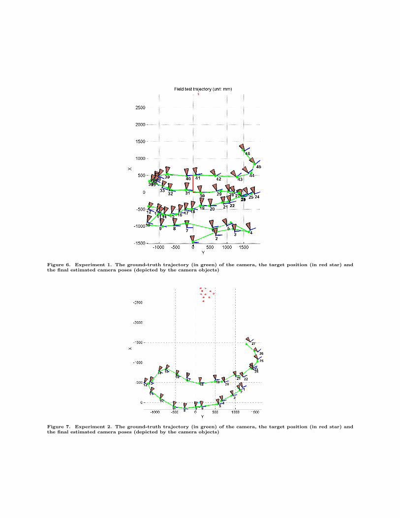
Figure 6. Experiment 1. The ground-truth trajectory (in green) of the camera, the target position (in red star) andthe final estimated camera poses (depicted by the camera objects)
Figure 7. Experiment 2. The ground-truth trajectory (in green) of the camera, the target position (in red star) andthe final estimated camera poses (depicted by the camera objects)
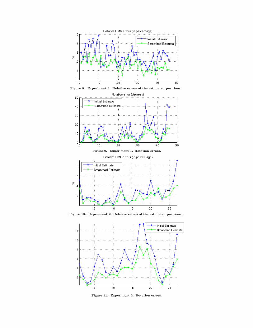
Figure 8. Experiment 1. Relative errors of the estimated positions.
Figure 9. Experiment 1. Rotation errors.
Figure 10. Experiment 2. Relative errors of the estimated positions.
Figure 11. Experiment 2. Rotation errors.