e i • t i studies and analyses i of the space shuttle main ... · of the space shuttle main...
TRANSCRIPT

II
I
I
e
¢
, i
• t"
STUDIES AND ANALYSESOF THE
SPACE SHUTTLE MAIN ENGINE
i Contract No. NASw-3737
II
iI
Technical ReportCovering
SSME FAILURE DATA REVIEW,DIAGNOSTIC SURVEY AND
SSME DIAGNOSTIC EVALUATION
i BCD-SSME-TR-86-1
I
IDecember 15, 1986
R.C. Glover, B. A. Kelley and A. E. Tischer
I
!Prepared For
National Aeronautics and Space Administration
I George C. Marshall Space Flight CenterMarshall Space Flight Center, AL 35812
I
II
BATTELLEColumbus Division
505 King Avenue
Columbus, Ohio 43201-2693
co
u) v_
I _1_
\
:'4r_D
L_ t.._t I.-_4,,.-I
https://ntrs.nasa.gov/search.jsp?R=19870005835 2020-03-31T16:38:51+00:00Z
III
IIIIIlII|
IIli
II
I
STUDIES AND ANALYSESOF THE
SPACE SHUTTLE MAIN ENGINE
Contract No. NASw-3737
Technical ReportCovering
SSME FAILURE DATA REVIEW,DIAGNOSTIC SURVEY AND
SSME DIAGNOSTIC EVALUATION
BCD-SSME-TR-86-1
December 15, 1986
R. C. Glover, B. A. Kelley and A. E. Tischer
Prepared For
National Aeronautics and Space Administration
George C. Marshall Space Flight Center
Marshall Space Flight Center, AL 35812
/_ E. Tischer
Manager
SSME Study
N. H. Fischer
Manager
Space Systems Section
BATTELLEColumbus Division
605 King AvenueColumbus, Ohio 43201-2693
!
II
I
ii
iI
I
I
Ii
i
I
I
I
I
I
I
ABSTRACT
The results of a review of the SSME failure data for the period 1980 through
1983 are presented. The data was collected, evaluated and ranked according to
procedures established during the study. A number of conclusions and
recommendations are made based upon this failure data review. The results of
a state-of-the-art diagnostic survey also are presented. This survey covered
a broad range of diagnostic sensors and techniques and the findings have been
evaluated for application to the SSME. Finally, a discussion of the initial
activities for the on-going SSME diagnostic evaluation is included.
I
!I
!
!!
!!!!
I!!II!I!
!
!
TABLE OF CONTENTS
SUMMARY ...............................................................
Introduction .....................................................
SSME Failure Data Review .........................................Diagnostic Survey ................................................
SSME Diagnostic Evaluation .......................................
On-Going Research ................................................
INTRODUCTION ..........................................................
SSME FAILURE DATA REVIEW ..............................................
Failure Modes Analysis ...........................................
Data Collection .............................................UCR Review ..................................................
SSME Accident/Incident Reports Review .......................
Failure Modes and Effects Analysis Report Review ............Test Firing Cutoff UCRs Review ..............................
Failure Mode Ranking ........................................
Measurement Parameter Analysis ...................................
Conclusions ......................................................Recommendations ..................................................
Partially Developed and Tested ..............................
Devices with Major Development Efforts Needed ...............
DIAGNOSTICS SURVEY ....................................................
Survey Approach and Methodology ..................................
Approach ....................................................
Methodology .................................................
Diagnostics Background ...........................................
Definitions .................................................
State Identification Process Hierarchy ......................
Information Acquisition .....................................Information Reduction .......................................
State Identification ........................................
Summary and Conclusions .....................................
Paqe
1
11356
9
9
9
1017
18
19
2O
22293O
3233
35
35
3536
37
373940414243
I

TABLE OF CONTENTS
SSME Diagnostic and Maintenance System Overview ..................
Information Gathering .......................................Information Reduction .......................................
Diagnostic Decisions ........................................
Summary .....................................................
Survey Findings ..................................................
Liquid-Fueled Rocket Engines ................................Aircraft ....................................................
Non-Aerospace Industries ....................................
Recommendations ..................................................
Data Acquisition ............................................
Signal Processing ...........................................
Diagnostic Techniques .......................................
SSME DIAGNOSTIC EVALUATION ............................................
Issues and Approach ..............................................
Failure Information Propagation Model ............................
FIPM Example .....................................................
High-Pressure Oxidizer Turbopump FIPM ............................
Revised FIPM Methodology .........................................FIPM Status ......................................................
ON-GOING RESEARCH .....................................................
DATA SOURCES ..........................................................
Liquid-Fueled Rocket Engine Diagnostics ..........................Aircraft Diagnostics .............................................
Non-Aerospace Diagnostics ........................................
REFERENCES AND BIBLIOGRAPHY ...........................................
ii
44
46464647
47
475158
62
626464
67
676869737778
81
83
838383
85
I
!Ii
!!
I
iI
!
I
I
I
I
I
|
I
i
!
!IlI
IIIIIIIItIIIi
Figure 1.
Figure 2.
Figure 3.
Figure 4.
Figure 5.
Figure 6.
Figure 7.
Figure 8.
Figure 9.
Figure 10.
Figure 11.
Figure 12.
Figure 13.
Figure 14.
Figure 15.
Figure 16.
Figure 17.
Figure 18.
Figure 19.
Figure 20.
Figure 21.
LIST OF FIGURES
Sample of First UCR Review Listing by Component ...........
Samples of First UCR Review Failure Mode Tables ...........
Sample of Second-Cut UCR Tables ...........................
Number of UCRS by Failure Type ............................
Number of UCRS by Component ...............................
Fault Tree Diagram for Hot-Gas Manifold ...................
Example of Test Firing Cutoff UCRs Review Tables ..........
Example of Measurement Parameter Tables ...................
Strategy for State-of-the-Art Survey of MachineDiagnostics ...............................................
Partitioning of System States Into Operational andErroneous States ..........................................
The Hierarchy of Process Required for State
Identification ............................................
Machine Control Versus Machine Diagnostics. Note
the Opportunity for Sharing Resources .....................
Overall SSME Diagnostics and Maintenance Picture ..........
Modules Comprising Exhaust Fan FIPM .......................
Connections Between Exhaust Fan Modules ...................
Addition of Failure Modes to Exhaust Fan FIPM .............
Failure Information Associated With Exhaust Fan
Connections ...............................................
Failure Information Grouped by Signal Type for theExhaust Fan FIPM ..........................................
Excerpt from Initial HPOTP FIPM ...........................
Key for Initial HPTOP FIPM ................................
Failure Information Matrix for Initial HPTOP FIPM .........
iii
Page
10
11
12
14
14
18
21
28
36
38
40
43
45
70
70
72
72
73
74
75
76
I
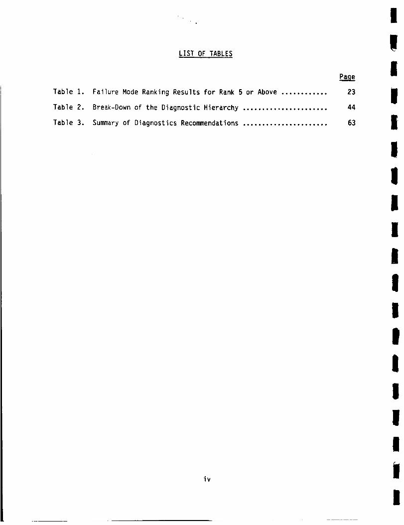
Table 1.
Table 2.
Table 3.
LIST OF TABLES
Failure Mode Ranking Results for Rank 5 or Above ............
Break-Down of the Diagnostic Hierarchy ......................
Summary of Diagnostics Recommendations ......................
iv
Pa_e
23
44
63
I
IIII
IIIIi
1i
IIIIIii

STUDIES AND ANALYSES OF THE SPACE SHUTTLE MAIN ENGINE
Contract Number NASw-3737
Technical Report
CoveringSSME Failure Review, Diagnostics Survey, and SSME Diagnostic Evaluation
SUMMARY
Introduction
The National Aeronautics and Space Administration (NASA) recently
has shown increased interest in condition monitoring and failure diagnostics
for the Space Shuttle program. This interest has been prompted primarily by
the need to reuse various Space Shuttle elements. NASA is emphasizing the
Space Shuttle Main Engine (SSME) as a key candidate for condition monitoring
and diagnostics.
This study was initiated by NASA to (1) review the SSME failure data
base and identify major failure types, (2) survey a broad spectrum of diag-
nostics and identify promising candidates for use on the SSME, (3) conduct a
systems-level analysis of the SSME diagnostic system using the outputs of
Items 1 and 2 and (4) make recommendations concerning improvements in the SSME
diagnostic system.
This technical report covers the following tasks of this study:
• SSME Failure Data Review
• Diagnostics Survey
• SSME Diagnostic Evaluation (on-going).
SSME Failure Data Review
The first task of the SSME study was to develop an understanding of
the engine operating characteristics and failure modes. The task included
collection and reduction of data on SSME failure modes, categorization of the
failure modes, ranking of the failure modes, identification and evaluation of
measurable parameters for each failure mode and identification of parameters
for possible trending information.

2
The initial activity on this task was a review of the available SSME
failure data. The information used in this study included all of the 3-1ine
UCRs written from January 1980 through November 1983, selected full-page UCRs,
the Rocketdyne Failure Modes and Effects Analysis (FMEA) Report and the $SME
Accident/Incident Reports for 1980 through 1983.
Approximately 3000 abbreviated UCRs were reviewed in this task.
This number was reduced to about 2900 by an initial screening process. The
next step in the data reduction was to chart the failure modes over time to
see the effects of the recurrence control procedures, to combine like failure
modes and to eliminate minor problems which did not reappear in the data. The
final step in the UCR data reduction was to collect the significant full-page
UCRs and to review the detailed information. At the conclusion of these three
screening processes, 1440 of the original UCRs were remaining. These UCRs
represented approximately 190 engine failure modes. The reduced UCRs were
plotted versus failure type. The UCRs were also plotted as a function of the
individual SSME components.
The eight SSME Accident/Incident Reports written between January
1980 and December 1983 were reviewed along with the FMEA Report. The review
of the FMEA Report led to the development of fault tree diagrams for each of
the major components to augment available data on the failure modes and their
propagations. The test firing cutoff UCRs were also reviewed to determine the
diagnostic role of the current SSME sensors. A procedure was developed for
ranking the failure modes identified by the data collection and screening.
The failure modes were ranked from i to 10, with 1 being the most critical.
The measurements necessary to detect each failure mode were identi-
fied and evaluated. The several hundred failure modes for the entire engine
can be reduced to about fifteen types of failures. The possible measurable
parameters for each failure mode are evaluated along with possible in-flight
and between-flight sensors or diagnostic techniques.
The conclusions drawn from the SSME failure data review include:
• Turbopumps have the highest priority, but other components have
failure modes which must be considered
• Major accidents have had random failure modes and the commonly
recurring failure types generally have not been to blame
• Many failure modes presently are detected too late to implement
engine shutdown without sustaining further damage

I
|
I
II
III
IiiiI
I
III
i
3
• UCR data from test firings indicate that the present sensors can
be useful in reliably diagnosing many failure modes
• Several recently developed and novel sensors could be useful for
detection of critical failure modes, especially in the high-
pressure turbopumps
• Many fatigue or wear-related failures can be trended by informa-
tion from conventional sensors.
The recommendations resulting from the SSME failure data review
include:
• The design and development of an integrated diagnostic system
should be pursued (including in-flight and ground-based elements)
• SSME failure diagnosis could be improved by analysis of the data
being collected by the current conventional sensors coupled with
signal processing and enhancement
• Promising sensing techniques which target major engine failure
modes should undergo further development and testing.
Diagnostic Survey
A survey of the state of the art of machine diagnostics was
performed as the second task in the SSME study. The primary goal was to iden-
tify new diagnostic sensors, processing techniques, and/or diagnostic
approaches which might be applicable to the SSME. A secondary goal of this
task was to identify the overall status of machine diagnostics and the rela-
tive position of the SSME diagnostic system within this framework.
The diagnostic survey section of this report begins with a number of
definitions and other general information regarding the nature of machine
diagnostics. This terminology and discussion is necessary to provide a
foundation for organizing the survey data.
A high-level overview of the SSME diagnostic and maintenance system was
also prepared to identify the major elements of the current diagnostic
approach and the interactions between them. This information was used as the
basis for evaluating items identified during the diagnostic survey.
The survey covered the three rather broadly defined applications
areas of (1) diagnostics for liquid-fueled rocket engines, (2) diagnostics for
aircraft engines, and (3) diagnostics for relevant non-aerospace industries.
I
4
The survey involved interviews with experts in NASA, USAF, and a broad range
of industries. In addition, relevant Battelle experts were interviewed and a
thorough literature search was performed.
The review of liquid rocket engines found that the SSME represented
the state of the art in nearly all respects. This is not a startling conclu-
sion in view of the fact that the SSME is the only major engine development
program funded over the last 15-20 years. The SSME diagnostic system is also
more sophisticated than its predecessors due to the engine's design
attributes.
Aircraft engines and their associated diagnostic systems have
received far more attention than the liquid rocket engines. This can be
attributed to a number of factors including the military emphasis on weapon
availability, the civilian air carriers' desire to reduce costs, and the FAA's
mandate to assure safety and reliability. This particular portion of the
survey was especially informative.
The non-aerospace industry has been somewhat slow in recognizing the
potential of machine diagnostics. This position is probably influenced some-
what by the higher safety factors which can be utilized in non-aerospace
machinery. This situation is changing rapidly for a number of reasons. A
number of potentially relevant techniques such as expert systems and pattern
recognition ultimately may be proven first in this arena.
The survey findings can be summarized as follows:
• Diagnostics on liquid-fueled rocket engines other than the SSME
were found to contain no novel techniques
• Diagnostics on jet aircraft engines currently use a number of
novel techniques that are not employed on the SSME
• Diagnostics in non-aerospace industries employ the entire
spectrum of sensors and diagnostic techniques.
As a result of the survey findings, the following recommendations
were made:
• The use of new types of sensors and an increase in coverage pro-
vided by on-board sensors
• The use of image processing techniques to assist in ground-based
inspections
• The use of pattern recognition to improve on-board diagnostics
I
!
I
II
IIlIl
!iI
I
I
II
|I

• The application of non-linear filters for ground-based analysis
• The establishment of an integrated data base system to include
all engine performance/historical data.
i
I
I
I
II
i
Ii
I
II
i
I
i
SSME Diaqnostic Evaluation
The third task of the SSME study is intended to assimilate the out-
puts of the SSME failure data review and the diagnostics survey and to use
this information for evaluating the current SSME diagnostic system. The prin-
cipal objective of this task is to identify potential means for improving the
availability of high-quality, pertinent engine data. This information will be
used both in-flight and on the ground to assess the condition of the SSME and
its respective components.
To accomplish the objective outlined in the preceding paragraph, an
analysis approach was formulated to address the key SSME diagnostic issues.
These issues centered on maximizing the information yield from the current
engine sensors. A secondary emphasis was placed on the efficient augmentation
of this system in cases where major failure modes were not adequately covered
by existing sensors.
The Failure Information Propagation Model (FIPM) was selected as the
analysis tool for use in this task. The FIPM is a technique developed by the
Battelle Columbus Division to qualitatively evaluate the potential test points
in a system. The objective of this qualitative evaluation is to assess the
information bearing value of each test point. The model assumes that the
system being depicted is in a near-normal state of operation.
The high-pressure oxidizer turbopump (HPOTP) was selected as the
initial SSME component for evaluation using the FIPM. An HPOTP FIPM was
graphically constructed using the steps outlined in the SSME diagnostic evalu-
ation section of this report. Subsequent to the development of the HPOTP
FIPM, a preliminary analysis of the HPOTP failure information was performed
using a failure information matrix. This matrix was used to develop a pre-
liminary set of test signature equations for the HPOTP.
Subsequent efforts to specify a set of diagnostic sensors which
would target all of the high-priority HPOTP failure modes encountered diffi-
culty due to the need for additional data. A decision was reached to restruc-
ture the HPOTP FIPM to include the additional data needed, to adopt a more
!

6
formal development methodology, and to implement the new procedure in a data
base format.
The revised FIPM methodology has been completed and documentation
will be provided in a subsequent technical report. The software associated
with the FIPM data base is currently under development. The revised HPOTP
FIPM presently is being formulated in parallel with the development of the
FIPM data base software.
On-Goinq Research
A number of activities are currently in progress or planned in
connection with this study. The tasks include:
• Development of FIPM data base software
• Generation and loading of FIPM data for the HPOTP
• Generation and loading of FIPM data for the following SSME
components:
- high-pressure fuel turbopump (HPFTP)
- low-pressure oxidizer turbopump (LPOTP)
- low-pressure fuel turbopump (LPFTP)
- oxidizer preburner (OPB)
- fuel preburner (FPB)
- main combustion chamber (MCC)
- heat exchanger (HE)
- main injector
- nozzle
• Assessment of candidate diagnostics
• Analysis of existing engine data
• Examination of on-board implications of SSME diagnostics
• Recommendations for diagnostic system development.
!III
lI
I
t
It
i!
Il
I
!IiiII
II
m
I,iII
II!II
IIII
I
III
INTRODUCTION
The National Aeronautics and Space Administration (NASA) recently
has shown increased interest in condition monitoring and failure diagnostics
for the Space Shuttle program. This interest has been prompted primarily by
the need to reuse various Space Shuttle elements such as the Orbiter, Space
Shuttle Main Engines (SSMEs) and Solid Rocket Boosters (SRBs). The reuse of
these major hardware items has created additional requirements for acquisition
of valid wear and failure data on key Space Shuttle subsystems and components.
This information is needed to verify the proper functioning of the Space
Shuttle during its mission as well as to evaluate the maintenance required
between flights. The principal NASA goals for improved monitoring and
diagnostic systems are increased Space Shuttle reliability and safety coupled
with reduced maintenance and turnaround costs.
NASA is exploring the entire spectrum of monitoring and diagnostic
techniques for potential application to the Space Shuttle program. Research
is being conducted in the areas of instrumentation, data acquisition, data
analysis, automated decision making, and automated record keeping. Several
NASA field centers and a number of contractors are currently involved in these
evaluations. Since diagnostics, as a science, is still in the early stages of
development, much of this work is very fundamental and exploratory in nature.
However, with recent technological gains in the field of electronics, specifi-
cally microprocessors and computers, the capability of performing comprehen-
sive diagnostics and condition monitoring tasks is now limited primarily by
the availability and reliability of the appropriate transducers, and by the
ability to understand and interpret the data being collected.
NASA is emphasizing the SSME as a key candidate for condition moni-
toring and diagnostics. The need for additional SSME data is the direct
result of the engine's vital role during Space Shuttle launch and ascent. The
ability to monitor, diagnose, and control degradations or failures of an
operating engine is very important to both crew safety and mission success.
It is also desirable to obtain an accurate assessment of the engine's overall
condition after completion of the firing cycle. Decisions concerning an
engine's suitability for a subsequent mission and the extent of any post-
flight maintenance or repairs require detailed data on major engine com-
ponents. Information on engine condition both during and after firing is
I

8
equally important for ground test operations. However, the goal of accurately
monitoring and diagnosing conditions in the SSME is complicated by a number of
factors including the general engine design which maximizes performance while
minimizing size and weight, the severe thermal and acoustic environments dur-
ing engine operation, the reactivity and other properties of the liquid oxygen
and liquid hydrogen propellants, and the extremely small time constants asso-
ciated with major degradations and failures.
This study was initiated by NASA to (1) review the SSME failure data
base and identify major failure types requiring diagnostic monitoring,
(2) survey a broad spectrum of diagnostic sensors and processing techniques
and identify promising candidates for application to the SSME, (3) conduct a
systems-level analysis of the current SSME diagnostic system using the outputs
from Items 1 and 2, and (4) make recommendations concerning improvements in
the SSME diagnostic system and approach.
The task reports presented here cover three efforts to provide NASA
with information to determine the major SSME failures, means to detect indi-
cations of failures in time to take appropriate actions, and ways to evaluate
the need for and usefulness of those means.
The task reports accordingly cover and are entitled:
• SSME Failure Data Review
• Diagnostics Survey
• SSME Diagnostic Evaluation.
The SSME failure data review has been completed from the standpoint
that the data from January 1980 to November 1983 has been collected and
analyzed for use in the diagnostic evaluation and other areas. The diag-
nostics survey has similarly been completed, with the information being
incorporated in the diagnostic evaluation as well as providing a background
for other work. The SSME diagnostic evaluation is being performed using
Battelle's Failure Information Propagation Model which is described in the
third section of this report. The FIPM process will rely heavily on the data
collected and assessed in the first two tasks. Detailed results from the FIPM
are only now being realized, and these are to be presented in a separate
report.
i
Ii
II
Ii
I
II
I
II
II
Ii
I
IIIII
Ii!IIIIIIIIII
9
SSME FAILURE DATA REVIEW
The first task of the SSME study was to develop an understanding of
the engine operating characteristics and failure modes. The task included
collection and reduction of data on SSME failure modes, categorization of the
failure modes, ranking of the failure modes, identification and evaluation of
measurable parameters for each failure mode, and identification of parameters
for possible trending information. This information is necessary to evaluate
the effectiveness of diagnostic monitoring systems.
Failure Modes Analysis
Data Collection
Most of the data necessary for the failure modes analysis was sup-
plied by the Rocketdyne Division, Rockwell International Corporation, Canoga
Park, CA. The main source of information was the Unsatisfactory Condition
Reports (UCRs). Since there were many UCRs written and Rocketdyne's previous
study had included UCR information through 1979, it was decided in the present
study to review all UCRs in a three-line format from January 1980 through
November 1983. After the preliminary data reduction had taken place, selected
full-page UCRs were collected for review. Other supplemental information
received from Rocketdyne included the Failure Modes and Effects Analysis
(FMEA) Report and Accident/Incident Reports for 1980 through 1983.
To provide Battelle personnel with additional information, engine
data from a recent test firing and a Shuttle flight were obtained from NASA
Marshall Space Flight Center (MSFC) along with general information on the SSME
program. A diagnostics overview presentation was given by NASA Lewis Research
Center (LeRC) personnel along with other general information needed to educate
the Battelle researchers about various aspects of the SSME program. Informa-
tion was also obtained from Rocketdyne personnel at NASA Kennedy Space Center
(KSC) with regard to maintenance procedure and history.
I
10
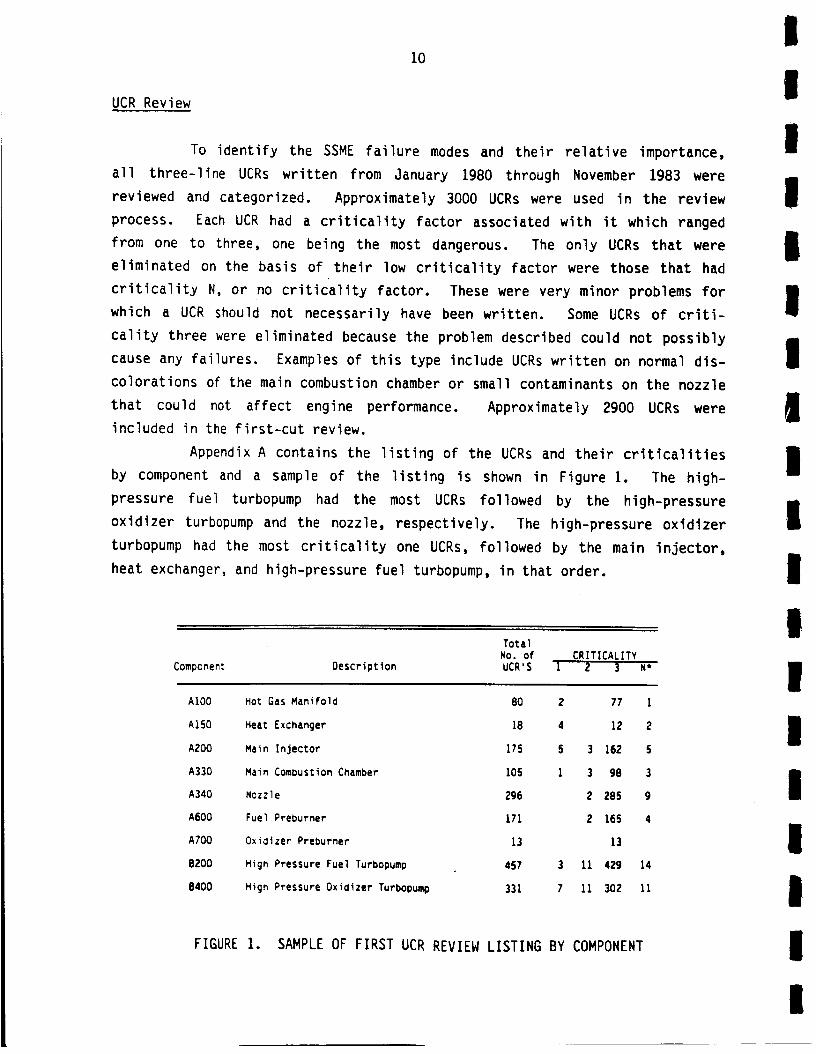
UCR Review
To identify the SSME failure modes and their relative importance,
all three-line UCRs written from January 1980 through November 1983 were
reviewed and categorized. Approximately 3000 UCRs were used in the review
process. Each UCR had a criticality factor associated with it which ranged
from one to three, one being the most dangerous. The only UCRs that were
eliminated on the basis of their low criticality factor were those that had
criticality N, or no criticality factor. These were very minor problems for
which a UCR should not necessarily have been written. Some UCRs of criti-
cality three were eliminated because the problem described could not possibly
cause any failures. Examples of this type include UCRs written on normal dis-
colorations of the main combustion chamber or small contaminants on the nozzle
that could not affect engine performance. Approximately 2900 UCRs were
included in the first-cut review.
Appendix A contains the listing of the UCRs and their criticalities
by component and a sample of the listing is shown in Figure 1. The high-
pressure fuel turbopump had the most UCRs followed by the high-pressure
oxidizer turbopump and the nozzle, respectively. The high-pressure oxidizer
turbopump had the most criticality one UCRs, followed by the main injector,
heat exchanger, and high-pressure fuel turbopump, in that order.
TotalNo. of CRITICALITY
Component Descriptlon UCR'S I 2 3 N*
AI00 Hot Gas Manifold 80 2 77 I
A150 Heat Exchanger 18 4 12 2
A200 Main Injector 175 5 3 162 5
A330 Main Combustion Chamber 105 I 3 98 3
A340 Nozzle 296 2 285 g
A600 Fuel Preburner 171 2 165 4
ATO0 Oxidizer Preburner 13 13
B200 High Pressure Fuel Turbopump 457 3 11 429 14
8400 High Pressure Oxidizer Turbopump 331 7 11 302 11
FIGURE 1. SAMPLE OF FIRST UCR REVIEW LISTING BY COMPONENT
I
I
II
1
|I
II
I
Ii
III
II

I
I
I
I
il
I
I
I
I
I
iIII
I
IIt
1
11
Appendix B contains a breakdown of the failure modes, cause, and
recurrence control for each component. A sample of these tables is given in
Figure 2. There were literally hundreds of failure modes identified, many
having several causes. A large percentage of the problems were assembly or
manufacturing problems. Most listed design, assembly, or manufacturing
changes to correct the problems.
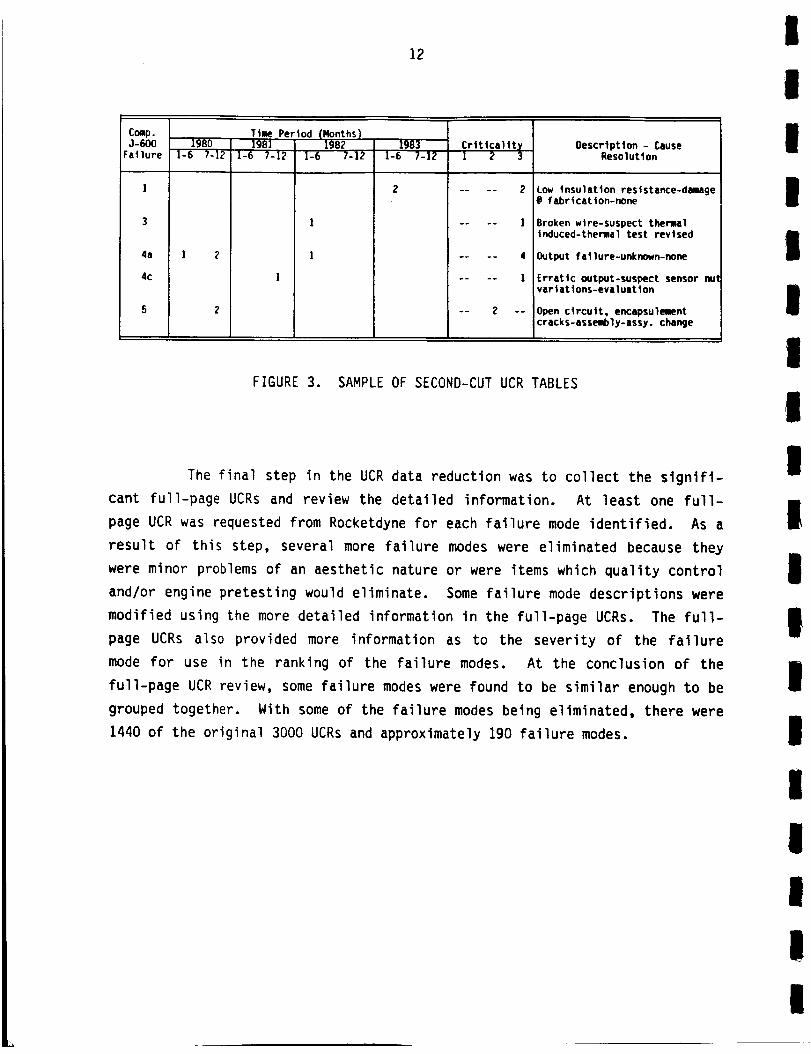
The next step in data reduction was to chart the failure modes over
time to see whether the recurrence control procedures had remedied the prob-
lems. Also, the failure mode listings were revised to combine like failure
modes and to eliminate those that were minor, had occurred only once or twice,
and where the corrective action showed that there were no recurrences. Appen-
dix C contains the results of this review and a sample is shown in Figure 3.
After this step, the number of UCRs remaining was approximately 1900 from the
original 3000 reviewed including 260 failure modes.
Fail. Failure Mode - Failure Cause - Total CriticalityID Recurrence Control No. I 2 3 N
Leak(a) Pin Plug Leak--Inadequate Seal--Add
Leak Test I(b) Wireway Leak--Epoxy Did Not Adhere--
Process Change 3(c) Internal Leak--Tolerance Stackup--
Detectable in Test 2(d) Hyd Oil Leak--Excessive Proof Test
Cycling--None 2(e) Static Seal Leak--Burr Induced Scratch--
New Inspection I
(f) Vent Port Leak--Defective O-Ring--Open 2(g) Wireway Leak--Inadequate Epoxy Coverage--
Spec. Change 2
2 Hydraulic Lockup Orift--Mfg. Error--Detectable--None S 5
3 Slew Rate Error--Contamination--None 2 2
FIGURE 2. SAMPLES OF FIRST UCR REVIEW FAILURE MODE TABLES
I
12
I
IC_.0-6O0 1980Failure I-6 7-12
1
3
4a I 2
4c
5 2
lime Period (Months)1981 1982
1-6 7-12 1-6 7-12
1
1
19831-6 7-12
Crltlcallt@I 2 3
-- • -- 1
.... 4
.... I
-- 2 --
Description - CauseResolution
Low insulation resistance-damage@ fabrication-none
Broken wire-suspect thermalinduced-thermal test revised
Output failure-unknown-none
Erratic output-suspect sensor nutvariations-evaluation
Open circuit, encapsulementcracks-assembly-assy, change
I
I!
!m
FIGURE 3. SAMPLE OF SECOND-CUT UCR TABLES
The final step in the UCR data reduction was to collect the signifi-
cant full-page UCRs and review the detailed information. At least one full-
page UCR was requested from Rocketdyne for each failure mode identified. As a
result of this step, several more failure modes were eliminated because they
were minor problems of an aesthetic nature or were items which quality control
and/or engine pretesting would eliminate. Some failure mode descriptions were
modified using the more detailed information in the full-page UCRs. The full-
page UCRs also provided more information as to the severity of the failure
mode for use in the ranking of the failure modes. At the conclusion of the
full-page UCR review, some failure modes were found to be similar enough to be
grouped together. With some of the failure modes being eliminated, there were
1440 of the original 3000 UCRs and approximately 190 failure modes.
m
I
m
mII
Im
Iim
I

i
I
l
I
I
I
!
!
i
I
I
!
I
!
!
I
13
Many of the failure modes in the UCR review were of an infrequent
nature and were the result of assembly, procedure, or repair mistakes. Only a
few of the failures were recurrent in nature and posed an important safety
risk. (Among these were turbopump bearing wear, turbine blade cracking,
nozzle leaks, injector erosion, and sensor system failures.)
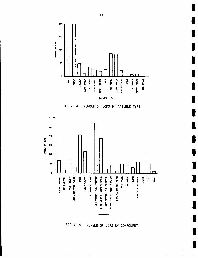
The failure modes were then placed Into fifteen categories and tabu-
lated for each component. This categorization resulted in a matrix which
forms Appendix D. Figure 4 gives one dimension of the matrix, the number of
UCRs versus failure type after the completed screening process. Cracking,
usually caused by vibration or thermally induced fatigue, was shown to be the
dominant failure type followed by various leakage problems. Most of the leak-
age UCRs were written on the nozzle coolant tubes which are mainly a time con-
suming maintenance item. The electrical problems mostly related to the
sensors and their associated wiring. Contamination was a significant problem
and was found on many of the components; it was usually caused by assembly
errors and some contamination could precipitate many other failures depending
upon the type of contaminant and location involved. Erosion was mainly a
problem in the high temperature areas such as the injectors, turbines, and
igniters. Wear was typically a problem for the high-pressure oxidizer turbo-
pump bearings and this has been a continuing problem on the SSME. Torque,
vibration, and excess travel problems are measurements made on the turbopumps
to check for problems before they lead to catastrophic failure. The rest of
the categories are not indicative of any particular component of the SSME.
Figure 5 shows the number of UCRs versus individual $SME components.
The dominance of the two high-pressure turbopumps along with the disparity
between the preburners are the most striking features in the graph. A
detailed listing of the failure types and causes for each component Is located
in Appendix E.
A brief description of the failure modes and general problems
for most of the major components follows:
High-Pressure Fuel Turbopump (HPFTP) - The turbine area of the HPFTP
is subjected to higher temperature and pressure than the other
turbopumps in the SSME and consequently has more problems. Erosion
and fatigue cracking were the subject of many UCRs for the turbine
blades, turbine sheetmetal, and preburner to turbine joint area.
i
300
250
200
iso
!I00
5O
3OO
i 200
i00
14
I
I
m
4_
FAILURE TYPE
1
II
FIGURE 4. NUMBER OF UCRS BY FAILURE TYPE
I
I
- !m
- I
l-1 lr il_ 7_TPlFIril-!_mz
Z
_ENTS I
FIGURE 5. NUMBER OF UCRS BY COMPONENT
I
I

i
g
I
!I
Ii
!!!
I!
!!
I
!!
!
15
The pump inlet and diffuser had a few failures along with some minor
bearing problems. Seal leakage and rubbing has been more of a prob-
lem than in the high-pressure oxidizer turbopump. Vibration due to
cavitation and possible near resonance vibration conditions have
been the subject of several UCRs.
High-Pressure Oxidizer Turbopump (HPOTP) - Bearing problems have
been a major source of UCRs for the HPOTP including severe vibration
levels during testing as well as bearing ball and race wear. Bear-
ing cage delamination has also occurred several times. Turbine
blade cracking and erosion has been a lesser problem on this turbo-
pump than for the fuel turbopump. Contamination and erosion of the
turbine area is also a concern. Turbine area rubbing and minor
sheetmetal cracking have also been reported.
Nozzle - Unlike the rotating machinery, the nozzle has only a few
problems. Cracking and leakage in the small nozzle coolant tubes
that line the inside of the nozzle are the most common source of
UCRs. Nozzle coolant tube leakage is caused by vibration fatigue,
thermal fatigue, and brazing anomalies in assembly or repair. While
these leaks are usually a nuisance item, the nozzle has been the
source of at least one catastrophic failure. A steerhorn rupture
caused by the use of incorrect weld wire during fabrication
destroyed an engine on the National Space Technology Laboratories
(NSTL) test stand.
Sensors and Electrical Harnesses - Sensor or sensor output failures
were a frequent problem and are to be expected in view of the envi-
ronmental extremes associated with the SSME. Typically, temperature
and pressure sensors had the highest failure rate. Sensor relia-
bility is an extremely important factor in designing an on-board
diagnostic system. To date, the only specific action taken with
respect to a postflight data review is to replace faulty sensors or
sensor cabling.
i
16
Fuel Preburner (FPB), Oxidizer Preburner (OPB), and Main Injector -
All three of these components have similar problems even though the
fuel preburner dominates the number of UCRs. This is probably due
to the higher temperature and pressure in the FPB. Erosion and
cracking of the LOX posts and injector faceplates are the most fre-
quent subject of the UCRs on the injectors. Vibration, temperature,
and nonconcentricity of the LOX posts are the primary causes of
injector failures.
Hot-Gas Manifold (HGM) - Cracking and rupture of ducting was the
primary failure mode and this is caused by vibration loading or
assembly error. Leakage at the joints along with loose fasteners
which could cause leakage was also a problem.
Main Combustion Chamber (MCC) - Most of the UCRs were written for
erosion or cracking on the hot-gas wall of the MCC. Low-pressure
fuel turbine drive manifold leaks were the only major failure occur-
rences for this component.
Heat Exchanger (HE) - There were few UCRs written for the heat
exchanger, probably because of the extreme precautions taken during
assembly. Small leaks of oxygen from the HE would be catastrophic,
so even minor tolerance and clearance discrepanices were reported in
UCRs.
Low-Pressure Turbopumps (LPFTP) and (LPOTP) - These had problems
similar to those for the high-pressure turbopumps, but they were
minor in nature and much less frequent.
Valves and Actuators - Leaks were the common thread throughout the
UCRs on these components. Internal leakage and ball seal leakage
occurred in various valves and actuators. Also, valves did not
function properly due to contaminants or a noisy or erratic position
transducer signal.
Igniter - The igniter UCRs usually dealt with either the electrical
connection or tip erosion failures.
I
III
I
IIi
II
II
I
IIliI

iL
I
II
I
II
II
III
I
I
II
I
17
Fuel Line, Oxidizer Line, and Drain Line Ducts - Joint problems and
joint leakage were the focus of most of these UCRs. Weld and seal
cracks also occurred.
Gimbal - Wear of the gimbal and cracks in the bushing were the two
failure modes which caused UCRs to be written for the gimbal.
SSME Accident/Incident Reports Review
Major failures of the SSME or its components are subjected to a
rigorous review with the results summarized in Accident/Incident Reports. The
eight reports written between January 1980 and December 1983 were reviewed for
failure mode information and the value of present instrumentation for failure
detection. Summaries of the individual reports are contained in Appendix F.
During this four-year period, there were no duplications of any of
these major failures. This indicates the complexity of the $SME and the
degree of randomness involved in the failures. The nonrepetitiveness of the
failures is also influenced by the detailed analysis of the incidents and the
corrective actions taken to prevent recurrence.
Certain reports showed that human error in the SSME fabrication and
assembly cannot totally be eliminated. The use of the wrong weld wire on the
steerhorn portion of the nozzle caused a catastrophic failure and a welding
mistake on the heat exchanger coil could have destroyed an engine or worse had
it gone undetected. The UCR data reviewed has shown that human error in
fabrication, assembly, and repair has been a constant source of problems.
Most of the catastrophic failures occurred on test stands after the
instrumentation had indicated an unsafe condition and shutdown procedures had
been started. In these cases, the time between detection of the measured
failure condition and the consequent engine destruction was much shorter than
the time to safely shut down the engine. To correctly and safely shut down
the SSME, deteriorating conditions must be detected earlier than is presently
being done. Because of the random causes of these major failures, the diag-
nostic system design should include as many of the engine parameters as is
economically and technically possible.
18
Failure Modes and Effects Analysis Report Review
The Failure Modes and Effects Analysis (FMEA) Report prepared by
Rocketdyne was reviewed to evaluate failure'modes to help in ranking them.
Although it was some help for major failure types and valve procedure prob-
lems, the FMEA Report did not contain a sufficiently thorough analysis of the
failure modes and their propagation paths.
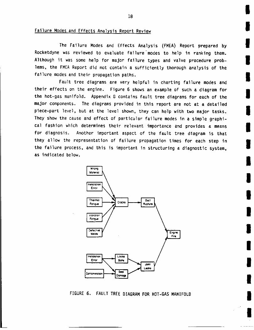
Fault tree diagrams are very helpful in charting failure modes and
their effects on the engine. Figure 6 shows an example of such a diagram for
the hot-gas manifold. Appendix G contains fault tree diagrams for each of the
major components. The diagrams provided in this report are not at a detailed
piece-part level, but at the level shown, they can help with two major tasks.
They show the cause and effect of particular failure modes in a simple graphi-
cal fashion which determines their relevant importance and provides a means
for diagnosis. Another important aspect of the fault tree diagram is that
they allow the representation of failure propagation times for each step in
the failure process, and this is important in structuring a diagnostic system,
as indicated below.
FIGURE 6. FAULT TREE DIAGRAM FOR HOT-GAS MANIFOLD
I
II
II
III
II
I
II
lI
IIl
I

19
Because the time between the duct rupturing and engine fire
(Figure 6) could be practially instantaneous, detection of such ruptures is
too late for shutdown and would not be an effective diagnostic measurement.
The diagram shows that cracking preceeds rupturing of the duct and may be
detectable for many seconds before rupture occurs. If the failure could be
detected at this level, the engine could be safely shut down and repaired. To
detect all the causes of cracking, however, might take a prohibitive amount of
time and be very costly.
In many cases, the most desired failure mode to detect may be
realistically undetectable because of the advanced level of technology needed
or because the environment within the engine would preclude measurement. In
these cases, ground inspection techniques for the failure modes may be
necessary. The fault tree diagram can be used to check the completeness of
the diagnostic system. If the system checks for cracking of the ducts, but
fails to detect loose bolts, the diagram in Figure 6 indicates that an engine
fire would still be a possibility. Thus, if a particular failure mode propa-
gates very quickly and there is presently no method for detection, then it may
be cost effective to develop an appropriate sensor.
To conclude, the FMEA report should be greatly expanded with inputs
from the Rocketdyne design groups for each particular component by assessing
the thermal and vibration environment in conjunction with the design
parameters.
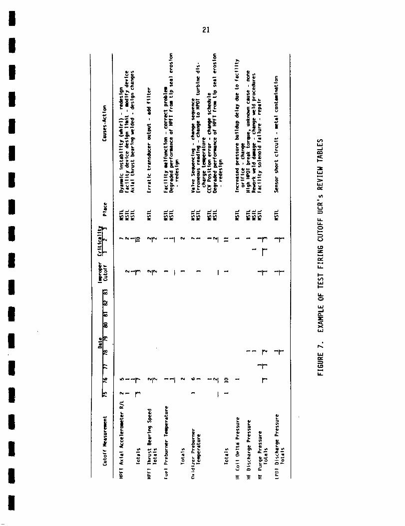
Test Firinq Cutoff UCRs Review
The UCRs that resulted from test firing cutoffs (shutdowns) from
early 1975 through late 1983 were reviewed to assist in determining the use-
fulness of the present sensors on the SSME for the design of a diagnostic sys-
tem. Even though the sensors produced a significant number of improper cut-
offs, as shown in the tables in Appendix H, there were also many shutdowns
that were due to valid measurements. These shutdowns were usually due to
simple signal-level-activated commands. However, several catastrophic
failures occurred after some safety limits ("red lines") had been exceeded but
before shutdown could be completed.

20
Figure 7 is an exampleof the tables of the reduced UCRdata. The
data are organized by the measurementthat caused shutdown. The year ofoccurrence, the numberof improper cutoffs, the criticality of the UCR, theplace they occurred, and the determined cause and action taken are included inthe table. If there was a valid reason for the measurementto have exceeded
the appropriate "red line" level, it was not an improper cutoff. Of over 255test firing cutoffs, 41 (16 percent) were the fault of the test facility or
the controller; 130 (51 percent) of the UCRs involved cutoffs for validreasons.
This does not, however, meanthat a similar event would result in an
engine shutdownduring flight. The importance of engine power output to thesafety of a flight is such that manyundesirable conditions would be accepted,but the basis for an overall diagnostic system may well reside with these
previously used basic sensors. Other activities, moreover, will be required
to adapt these sensors. For example, signal processing techniques, such asfrequency domain and trend analysis, may be utilized to locate specific
failures. Outputs from several sensors may indicate a unique failure mode(pattern recognition). Downstreamand upstream sensors can be used to vali-
date sensor output to improve the reliability of any diagnosis. Someof these
techniques can be used for prognostic monitoring, and with the inclusion of aground-based data acquisition and maintenance computer system, the results can
be in the maintenance personnel's hands before the Shuttle returns. Such an
"expert system" would be too slow for on-board diagnosis using today's com-puter technology, but maybecomea viable on-board tool in the future.
For the most part, fast-propagating and high-criticality failure
modesare key targets for any on-board diagnostic or shutdowndecisions. Thepresent sensors should be helpful, but optimized placement of these sensors
may be necessary. Also, knowledge of the background signal levels andexpected signal levels of the failure modesis important.
Failure Mode Ranking
To assess the importance of each failure mode to the design of a
diagnostic monitoring system, a procedure for ranking the failure modes was
developed. Three factors were given equal weighting for the ranking:
III
II
III
II
I
Il
II
lI
II
I
I
I
I
I
I
I
l
I
I
I
I
I
|I
II
I
II
[
==
..)
21 c
- o
c'_ _ ,,, o ,_ -
i ! "_"°_--_ - _ _; _ i-_
3_ "O O
_= _
"_-= gt [= " "_g'| c= =,- __. .;_,=
_'-_- i _-_!
P- r" I -"I - - " "_ "_"
-t"
-- r" -_"
-_-
- _ - I
g !".=o o _ _o .-o
= = _. _ - _ = -
w.-I
IJJ
t_J
¢11
-=
IJ--L_
Z
IJ.
IJJ}--
L,
tJJ
3'<
IJJ
IS.
I

22
Cost Factor - estimated cost per year of the failure
after subtracting the cost that diagnostics
could not eliminate
Risk Factor - based on the criticality factor
Time Factor - estimated time for failure mode to
propagate to a catastrophic failure
A detailed explanation of the ranking procedure is in Appendix I along with
the tabulated results. The failure modes are ranked in categories of import-
ance from 1 to 10, with 1 being the most critical and 10 the least.
Failure modes in Categories 1 through 5, listed in Table 1, are most
important and must be considered in the design of an on-board diagnostic
system. In Categories 6 through 10, some failure modes may still be economi-
cally included in an on-board system although they are not ranked very high.
Their inclusion should depend on the additional cost involved to detect each
failure mode. Due to economic and technical considerations, some highly-rated
failure modes may be impossible to include in an on-board system in the near
future, but they are important areas for research and development of either
in-flight or ground-based detection methods.
Measurement Parameter Analysis
Once the importance of the failure modes to the design of a diag-
nostic system has been evaluated, the measurements that can detect each
failure mode must be identified and evaluated. To evaluate the measurement
parameters, certain factors must be assessed such as signal level, background
noise, existence of commercially available transducers, feasibility of devel-
oping special transducers, and the information necessary to uniquely identify
the failure modes.
Signal level and background noise can only be roughly evaluated by
experience and engineering judgment. An important step in evaluating signal
levels quantitatively is to review the real-time data recordings of test stand
and flight engine firings. Analyzing the real-time analog data should provide
enough information to assess signal and noise levels, and may also indicate
signal processing enhancements that would discriminate particular failure
occurrences.
III
II
III
II
I
II
II
II
II

I
I
I
23
TABLE i. FAILURE MODE RANKING RESULTS FOR RANK 5 OR ABOVE
IRANK COMPONENT FAILURE MODE
HPOTP Vibration - bearing loading
I
II
lI
II
II
I
I
2
3
4
Heat Exchanger
Hot-Gas ManifoldHot-Gas Manifold
Main InjectorHPOTP
MCCHPFTP
Sensors
Nozzle
Fuel Preburner
HPFTPHPFTP
HPFTP
Ball Valves
Poppet ValvesSensors
Main InjectorFuel Preburner
Fuel Preburner
Fuel PreburnerHPFTP
HPFTP
HPFTPHPFTP
HPOTP
HPOTP
Check Valves
IgniterElectrical Harnesses
Electrical HarnessesElectrical Harnesses
Duct Seals
HPOTP
Cracks, leak in coil
Cracks, rupture in duct
Leak in MCC ignition jointASI supply line cracks
Bearing ball and race wear
Turbine drive manifold leak
G-5 joint erosion
Temp. and press, output failuresSteerhorn rupture
Faceplate erosionDiffuser failureInlet failure
Missing shield nuts
Ball seal leak and ball meltingCracked poppet
Temperature sensor debonding
Heat shield retainer cracks
Baffle and LOX post erosionBaffle, molyshield, and liner cracks
Missing/extra support pins
Turbine blade and platform erosionSeal cracking
Coolie cap nut crackingBroken turbine bladesTurbine blade cracks
Bearing cage delaminationCheck valve leaks
Igniter tip erosionBirdcaged harness
Loose, defective connector
Debonded torque lockSeal damageVibration level - cavitation
I
II
I
24
With reference to Figure 4, the several hundred failure modes for
the entire engine can be reduced to about fifteen failure types. In parti-
cular leaks and cracks are by far the most common failure type among all the
failure modes. Each failure type has a unique signature, but since many
failure modes have the same failure type, it may be difficult to identify a
particular failure mode. A brief description of each failure type, the nature
of the signal produced, and the possibility of identifying individual failure
modes follows:
Leaks - Leakage of a liquid or gas from the system, or from one com-
ponent to another within the system, can occur in several ways. It
may be due to a crack in a structure, a bad seal, or possibly a mal-
functioning valve. Presently, leaks are detected between flights by
pressurizing the system with helium. The signals produced by leak-
age for possible in-flight detection are sound, vibration, optical,
and possibly, in some cases, temperature or engine performance. In
most cases, the sound and vibration signals will be low when com-
pared to the background noise, probably even at ultrasonic frequen-
cies (acoustic emission frequencies). An acoustic emission method
for leak detection would moreover require many transducers to detect
all the possible places that leaks can occur even if selected as a
between-flight method of leak detection. Optical methods such as
holographic leak detection are still in the developmental stages and
also have resolution problems in detecting small leaks and are more-
over only applicable where easy access is possible (e.g., for
external leakage). In many cases, indirect measurements such as
temperature, flow, or pressure may infer leakage. For example,
leakage of hot gas into coolant passages could be detected by
temperature measurements. Also if the leakage is severe enough, it
will affect the downstream pressure and flow.
Cracks - Cracking of a structure is usually caused by mechanical or
thermal loading which can eventually lead to failure of the struc-
ture with possible secondary effects such as fluid leakage. One
present method of detecting cracking is by measuring the acoustic
signal in the structure's material caused by the energy released
through the cracking phenomena. These signals are detected by
acoustic emission transducers at a frequency dependent upon
I
I
I
I
I
II
II
II
I
II
III
II
I!
I
I!
II
!!!
!!
!
II
!I
I
25
material properties. High background noise, however, may be a prob-
lem in the application of this technique to many parts of the $SME.
Other detection methods include magnetic, electric potential, and
mechanical impedance methods. When the cracking leads to other
problems, detection of these failure modes may be easier. But,
since these are secondary effects, catastrophic failure of a com-
ponent may be imminent, and the ability to shut down the $SME with
minimal damage at this point may be impossible. Nevertheless, pre-
dicting cracking by trending vibration and temperature data should
be useful in monitoring structural fatigue life.
Erosion - Erosion of surfaces usually occurs in the hot-gas turbine
sections of turbopumps and in injectors. In the case of injectors,
local hot spots may indicate erosion. In the case of both turbine
and injector erosion, the performance of the turbopump and down-
stream components will directly be affected and should give rise to
indicative measurements. Temperature trending of these components
may be the most useful measurement possible in flight. Detection of
ablated particles or, more likely, surface wear is possible in the
case of erosion. Isotope wear detection, presently being developed
by Rocketdyne, is considered to have the best chance of success for
erosion detection.
Wear - Wear is caused by surface friction on a component due to
mechanical contact or flow impingement. Erosion is a special case
of wear, but it has been considered in a separate category of its
own. Wear was considered, in this study, to result from mechanical
contact between components with relative motion. Wear in the $SME
generally occurs in the rotating machinery, e.g. the turbopumps.
Bearings are the most critical parts affected by wear, followed by
seals. Rubbing usually causes vibration, and in many cases the
nature of the vibration signal can be used to identify which parts
are involved. For example, seal rubbing may involve some RPM
related vibration as well as indirect measurements such as reduced
shaft RPM and torque. Wear is usually detected at high frequencies
where the ambient noise is relatively low. More accurate measure-
ments may be made by isotope wear detection (but not for pitting),
!
26
magnetic wear detection, or ultrasonic doppler transducer. Magnetic
wear detection measures the ball passage frequency. Ultrasonic
doppler transducers can detect the shaft vibration, and should be
more sensitive to bearing wear than vibration of the housing.
Detection of worn particles or surface wear is also possible, as in
the case of erosion. Isotope wear shows the most promise in this
category. All these wear detection methods, moreover, are nonintru-
sive. Another possible wear measurement device, the fiberoptic
deflectometer, however, would be intrusive.
Dings, Dents, and Damage - This is a general category that usually
relates to debris impacting a part of the SSME. This can usually be
detected by vibration sensors as a high-energy impulse signal.
Electrical - Electrical problems is this study relate to sensors,
sensor cabling, and electrical connections. Many systems presently
can self-check for continuity and other transducers can be used to
verify the validity of a sensor's output (analytic redundancy),
rather than using multiple sensor redundancy to increase sensor
reliability.
Contamination - Contamination is a broad category of foreign depo-
sits or objects present in a component. In most cases there is
little or no effect, but problems such as reduced coolant flow
through passages and impaired valve operation can occur. The
effects of contamination can manifest themselves in different ways,
but temperature, flow, and pressure measurements generally provide a
good indication of a serious contamination problem.
Delamination and Broken Parts - These failure types are further
extensions of cracking and several other failure types previously
discussed. When a part fails structurally, the vibration signal
will increase dramatically in most cases, but catastrophic failure
of the engine may also be imminent.
Loose Parts - This cateogry usually refers to connections involving
bolts or other fasteners. The possibilities for detection include
increased vibration levels, an optical method, and measurement of
torque on the bolt.
I
III
III
i
Ii
Ii
I
III
II!

I
I
I
I
I
I
I
l
I
I
I
I
I
I
I
I
I
I
27
Missing/Extra Parts - This failure type is usually a problem with
stud keys or other small parts that are installed in large quanti-
ties. Inspection and verification during assembly or between
firings is the only way to directly detect missing or extra parts.
One verification method might involve accurately weighing subcom-
ponents before final assembly. Missing/extra parts may also result
in another failure type that may be detected in flight, e.g. loose
bolts.
Torque, Vibration, and Excess Travel - These measurements have all
been used as criteria for assessing turbopump condition. All three
have the potential for being performed in flight and could be used
in combination to adequately evaluate turbopump condition.
Tolerance - Tolerance problems can possibly be detected in flight by
optical methods, but ground inspection is usually required. Optical
methods for enhancing ground-based inspection of injector parts
could possibly save time, but these techniques will need extensive
development.
Information on potentially useful transducers for detecting particu-
lar failure modes came from several sources including the diagnostic survey
conducted as part of this study, the Rocketdyne Reusable Rocket Engine Main-
tenance Study, Final Report, and Battelle's past experience. Detailed des-
criptions of several promising sensors and diagnostic techniques are included
in this section's recommendations or in the section covering the diagnostic
survey.
To evaluate diagnostics for detection of particular failure modes, a
Battelle developed tool, the Failure Information Propagation Model (FIPM), has
been used and is described in detail in a subsequent section of this report.
This tool can be used to evaluate the information at a transducer location and
to assess the ability of the entire transducer set to identify engine failure
modes.
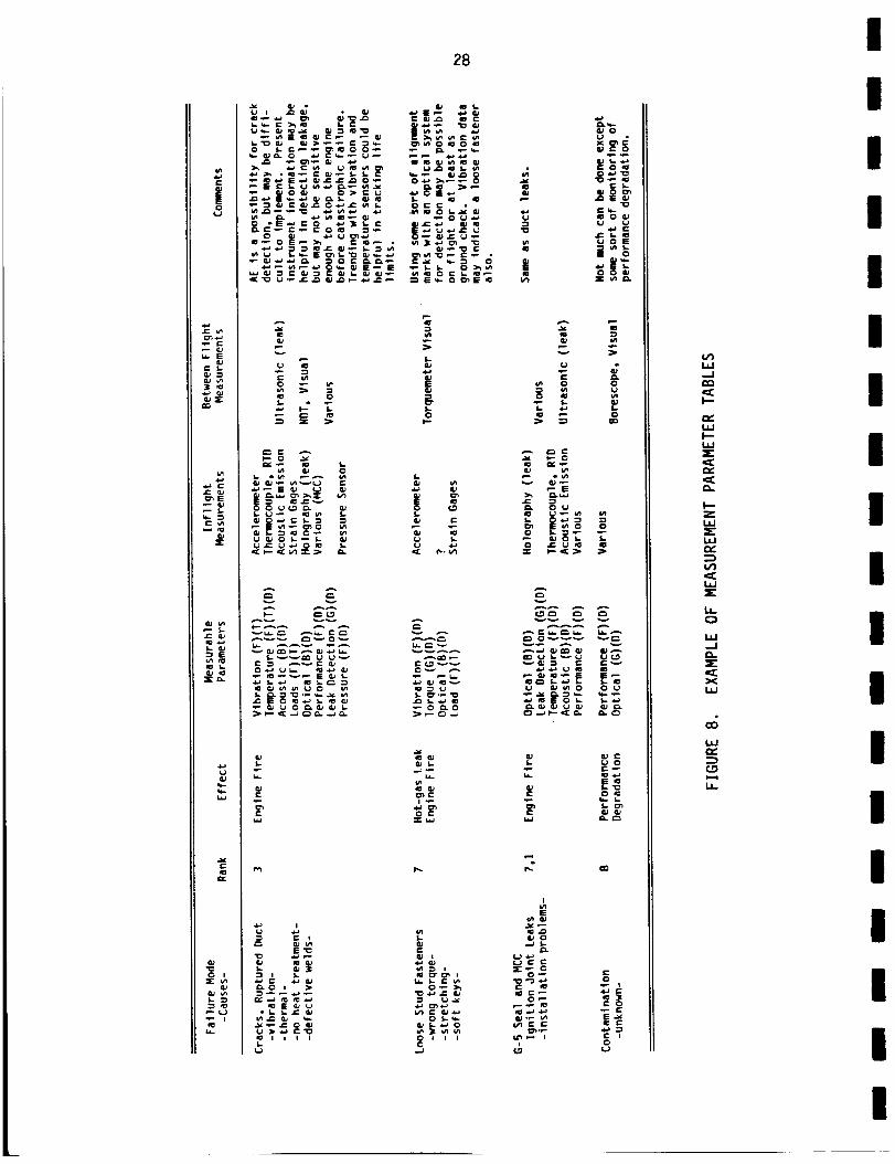
The results of the measurement parameter analysis for each compoent
are described in tabular form in Appendix J. A sample table of results is
shown in Figure 8. The failure modes, their causes, rankings, and effects are
listed in the tables. The possible measurable parameters for each failure
I
e-
|O
ccJ
_E
_r
E
U
w
C
C iX
28
_ C i_ m e m
v
_v v_
vvvvv_A
f: ¢_ vvOv ,_.
e-
e-
"10
|
•-_ e- I
I_e- o
"o
_ _ o
_ ov Iu_
_ E
v_ v
vcu _ e, e-v
o
E
cu o
IU I
_,
0 I I I
3
e. o
|-_
0
w,_1
j--
w
I--zw
u_
w,,.1
xw
hJ
[1
III
II
II
iI
II
II
I
III
Ii
I
I
II
I
II
III
II
I
II
II
I
29
mode are listed along with possible in-flight and between-flight sensors or
techniques. Additional comments are also supplied to indicate relative
strengths and weaknesses of the measurement techniques.
For most failures, the possibility exists to trend or detect their
occurrence with conventional transducers that are already being used on the
SSME. The problem is that current engine transducers may not be strategically
located for detection of many of these failures. Knowledge of the signal con-
tent is also insufficient to differentiate between the many possible failure
modes detectable by a given transducer. There are also some transducing
methods that need development, but which have excellent promise for detecting
failure modes which are undetectable by conventional methods.
The use of sensor data for failure trending could reduce the amount
of between-flight inspections. Any failure mode that involves a slow degrada-
tion or fatigue type of failure could be trended. Detailed descriptions of
measurements that can be used for trending particular failure modes are
included in the measurement parameter tables in Appendix J. Many fatigue
failures in the turbopumps and other components can be trended with mechanical
and thermal load history information obtained by accelerometers, other vibra-
tion transducers, and temperature sensors. Injector and hot-gas component
erosion can be trended with temperature measurements and, in some cases, pres-
sure measurements.
Conclusions
The conclusions drawn from the failure modes and measurement para-
meter analyses are:
• Turbopumps have the highest priority for in-flight monitoring,
but many other components also have high-ranking failure modes
which must be considered.
• Major accident failure modes have been random in nature and the
commonly recurring failure modes generally have not been to
blame. Many of the major accidents were due to either assembly,
manufacturing, or design problems which must be considered in the
development of a diagnostic system.
I

30
• Presently, many failure modes are detected too late to safely
shut down the SSME with minimal damage. The propagation rate of
many failure modes provides an extreme challenge in designing an
effective diagnostic system.
• Test firing cutoff UCR data reveal that the present sensors can
be valuable for reliably diagnosing many failure modes. This
could and should be achieved with proper signal processing, pat-
tern recognition (unique combination of sensor outputs), analy-
tical redundancy (correlate outputs from upstream and downstream
sensors), and development of more rugged sensors and cabling.
• Some recently developed and novel sensors could be useful for
detection of critical failure modes, especially in the high-speed
turbopumps. Some of these can target key failure modes that may
be masked from conventional sensors. They are described in the
diagnostic survey discussion or in this section's recommen-
dations. In many cases, there will be a great deal of develop-
ment required before these new sensors are flight ready. The
most immediate gains may be made by improving the use of the
present sensors.
• Many slow-developing fatigue or wear related failures can be
trended by information from conventional sensors, both to predict
eventual failure and to reduce the amount of between-flight
inspections. Such applications are possible for many turbopump
and injector failure modes.
Recommendations
Diagnostic monitoring of the SSME can be improved by better use of
present instrumentation, installation of more conventional sensors, and use of
some recently developed sensing techniques which target specific failure
modes. Three important steps for improving flight safety and maintenance
costs are:
• Design of an integrated diagnostic system including both
in-flight monitoring and ground inspection and maintenance.
III
II
III
II
I
II
II
III
I
i
I
II
II
I
III
II
I
II
II
I
31
• Improving failure diagnosis with conventional sensors by analysis
of present flight and test firing data as well as assessment of
signal processing and enhancement techniques to identify failure
modes.
• Further development and testing of promising sensing techniques
which target costly and hazardous failure modes that are diffi-
cult to detect with conventional sensors.
To design an effective diagnostic system for reduction of mainten-
ance costs, turnaround time, and catastrophic failure risk; failure informa-
tion in the entire SSME must be evaluated. The Failure Information Propaga-
tion Model (FIPM) is being used to evaluate failure information for all possi-
ble failure modes on the high-pressure oxidizer turbopump and assess sensing
opportunities at various locations in the turbopump. Once the FIPM is com-
pleted for all components, a qualitative evaluation of a complete SSME diag-
nostic system can be made. The FIPM will help determine how better to use
conventional and advanced technology sensors for in-flight monitoring and
trending of information in conjunction with necessary ground inspections. An
important aspect in the design of the complete diagnostic system is to incor-
porate an effective computerized information system for data processing and
retrieval. Such a system would give maintenance personnel the relevant infor-
mation to quickly assess and complete between-flight inspection and main-
tenance and would also be adaptable to incorporate new diagnostic
developments.
There are many opportunities to improve the capabilities of the pre-
sent sensor set as well as possible additional conventional sensors. The key
to developing the use of these sensors is analyze the recorded analog flight
and test firing data. By looking at the full bandwidth of the sensors, com-
bining various sensor outputs, and correlating the signals with the known
failure occurrences, diagnosis of many failure modes may be improved. Also,
the FIPM can be useful in identifying possible applications for the present
sensors and situations where additional conventional sensors would be helpful.
The reliability problems of the present conventional sensors can be attacked
by technological gains in hardening the sensors and through analytical
redundancy in checking the validity of the sensor outputs. Analytical
I

32
redundancy could reduce the number of sensors needed and thus reduce the
amount of sensor repair and replacement. Specific applications are detailed
in the measurement parameter tables in Appendix K.
Some new sensors may see applications on the SSME in the next couple
years and others could be developed for use on the engine within five years.
Most of these new or additional sensors target specific failure modes that are
both costly and not presently detectable by conventional sensors. A list of
the most promising sensors or sensing techniques follows:
Partially Developed and Tested
• Isotope Wear Detection - Between-flight noninstrusive detection
of slowly developing wear-related failure modes. Potential uses,
mainly in the turbopumps, include bearings, seals, and turbine
blades. Cannot detect cracking or pitting. Presently being
tested by Rocketdyne with funding from NASA LeRC.
• Ultrasonic Doppler Transducer - Nonintrusive means of detecting
shaft vibration through solid and liquid interfaces. Extremely
sensitive to imbalance and other RPM related vibration and may be
useful for detecting other failure modes on the information rich
shaft assemblies of the turbopump. It can detect cavitation,
bearing wear, and seal rubbing. Developed by Battelle and tested
at NASA MSFC in the mid-70's.
• Fiberoptic Deflectometer - Possibly more durable than conven-
tional accelerometers and can potentially target specific vibra-
tion problems that need intrusive measurement capabilities such
as bearing wear. Presently being tested at NASA LeRC by
Rocketdyne.
• Ultrasonic Flowmeter - Has been tested as a means of nonintru-
sively measuring flow through ducts. The mounting conditions,
however, have caused a duct to rupture. With proper design of
the duct and transducer mounting, this sensor is believed to be a
reliable method of detecting flow rate.
I
II
I
I
III
II
II
I
III
II
I
II
I
II
II
II
II
II
I
II
II
33
• Optical Pyrometer - For possible trending of turbine blade crack-
ing. May have resolution and calibration problems, but there is
no other acceptable method of detecting this failure mode at pre-
sent. Under test by Rocketdyne with funding by NASA LeRC.
• Borescope Image Processor - Off-the-shelf packages are available
to enhance the visual inspection of internal parts. New genera-
tion borescopes may be much better for low-light situations.
Devices with Major Development Efforts Needed
• Magnetic Wear Detector - A small experiment at Battelle showed
that the ball passage rate can be monitored by a Hall-effect
sensor. Bearing ball wear will change the contact angle and thus
the ball speed. If the signal can be cleaned up enough, higher
order effects may also be detected. Could be used as either a
flight sensor or ground inspection method.
• Acoustic Emission Detectors - Possible in-flight applications for
detecting cracks and leaks of quickly propagating failure modes.
May have resolution problems in high background noise environ-
ment. Cracks and leaks are by far the most predominate types of
failures.
e Laser Doppler Velocimeter - Can measure flow speed and direction,
but needs access via an optic fiber through a hole or "window".
e Tracers Added to Helium Leak Detection - A radioactive tracer
(Krypton, Tritium, etc.) could improve leak detection for ground-
based applications.
Holographic Leak Detection - Has the possibility of detecting and
locating leaks faster and more effectively than the present
helium method. Being investigated in a detailed Rocketdyne
study.
• Exo-Electron Emission - May be useful in ground inspection for
cracked parts. Also detailed in Rocketdyne study.
All of the above measurement applications should be evaluated for cost effec-
tive means of improving the present diagnostic system, but the most immediate
improvements should come through studying the on-board sensors.
I
34
(THIS PAGE INTENTIONALLY BLANK)
I
III
III
II
I
II
I
III
III

35
DIAGNOSTICS SURVEY
A survey of the state of the art of machine diagnostics was per-
formed as the second task in the SSME study. In this survey, a general look
was taken at the area of machine diagnostics across three rather broadly
defined application areas:
1. Diagnostics for liquid-fueled rocket engines,
2. Diagnostics for aircraft engines,
3. Diagnostics in relevant non-aerospace industries.
The survey involved interviews with experts in a broad range of industries,
NASA, and the military. In addition, relevant Battelle experts were inter-
viewed and the literature was reviewed. The current diagnostic methods for
the Space Shuttle Main Engine (SSME) were also examined and the relevant
survey findings were identified for potential use on the SSME.
Surve X Approach and Methodoloqy
Approach
This diagnostic survey has two objectives: (1) the determination of
the state-of-the-art of machine diagnostics, and (2) the identification of
new, candidate diagnostic techniques and/or approaches for potential applica-
tion to the SSME. Throughout this effort, the focus is on those techniques
that are considered to be off-the-shelf, or mature areas of research and
development.
The intent of the diagnostic survey is to be broad, spanning as wide
a spectrum of industries as possible. Within the general area of machine
diagnostics, three topics are considered:
1. Maintenance logistics and strategies,
2. Diagnostic techniques,
3. Design approaches for diagnostic systems.
_.C_DING PA&E BLAI_ NOT
|

36 !i
Because of its breadth, this study does not attempt to focus on any I
specific technique or approach in great detail. Throughout the survey, only
enough detail was sought to permit an assessment of the usefulness of the g
techniques under study.
Methodology I
There are two phases in diagnostics survey, a state-of-the-art sur- g
vey and the subsequent assessment of the survey findings. For the survey mphase, we selected three application categories: B
1. Diagnostic systems for liquid rocket engines,
2. Diagnostic systems on civil and military aircraft, m
3. Diagnostic systems in non-aerospace industries.
Information was gathered using literature reviews and interviews g
with a number of industry, government, and military experts. Figure g depicts gkthe overall
survey strategy, g
,!ROCKET ENGINES
JMANUFACTURERS
IINTERY IEWS
BATTELLE EXPERTS
IINTERVIEWS
AIRCRAFT
J\MILITARY CIVILIAN
/ /\LITERATURE
,INTERVIEWS
NON-AEROSPACE
MILITARY
/AIR CARRIERS MANUFACTURERS INTERVIEWS
I /\INTERVIEWS LITERATURE INTERVIEWS
CIVILIAN
/\INTERVIEWS LITERATURE
!I
I
!FIGURE 9. STRATEGY FOR STATE-OF-THE-ART SURVEY OF MACHINE DIAGNOSTICS I
!
I
I

!
|
IIt!ii
!IIIIII
II!!
liII!
37
The second phase of the Diagnostics Survey was a preliminary assess-
ment of the survey findings to screen out those that were not considered rele-
vant to the SSME. This was done in two steps:
1. The diagnostic systems and maintenance strategy currently
employed for the $SME were reviewed.
2. The survey findings were reexamined in light of the current SSME
environment, and those that were not considered useful were
dropped.
Information sources for the review of current SSME diagnostic sys-
tems and maintenance practices were NASA and Rocketdyne experts, and selected
published reports.
Diagnostics Backqround
By its very nature, machine diagnostics encompasses a broad set of
disciplines. Much of the scientific knowledge necessary to design and fabri-
cate machines, as well as to understand the physics of their failures, falls
under the technological umbrella of machine diagnostics. Because of this
breadth, it is necessary to provide an organization through a hierarchy of
related functions. This organization results in a logical, manageable set of
elements.
Definitions
We begin our discussion with a set of definitions to remove ambi-
guity in terminology. The following are taken from Reference 3-8:
• FAULT DETECTION - the act of identifying the presence of an
unspecified failure mode in a system resulting in an unspecified
malfunction.
• MALFUNCTION - an inability to operate in the normal manner or at
the expected level of performance.
• FAULT ISOLATION - the designation of the materials, structures,
components, or subsystems that have malfunctioned. Fault isola-
tion extends fault detection to the detection/identification of
the specific part that must be repaired or replaced in order to
restore the system to normal operation.
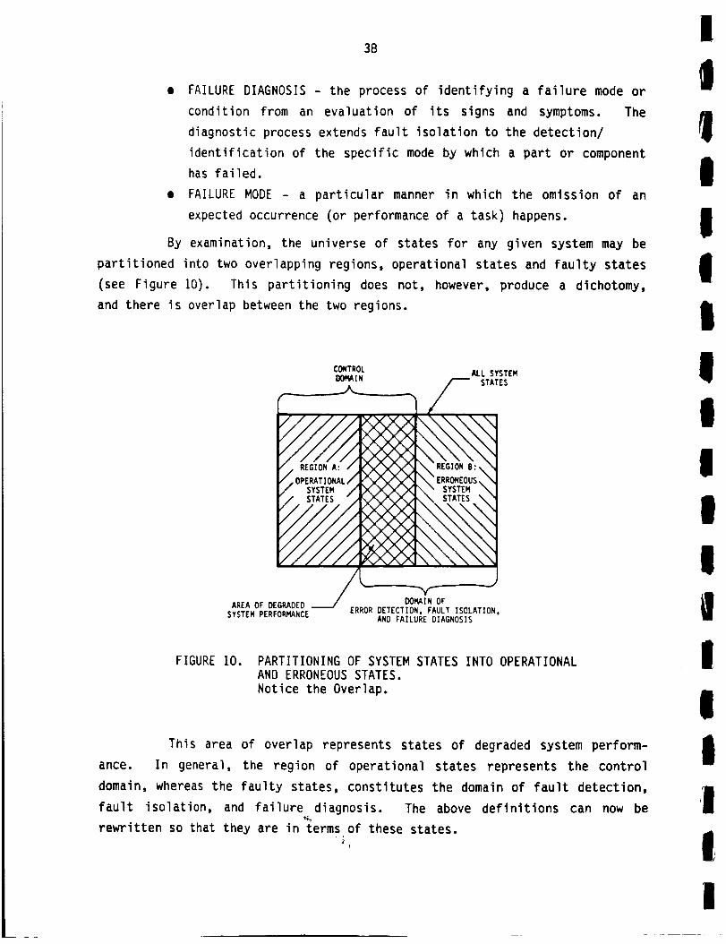
38
• FAILURE DIAGNOSIS - the process of identifying a failure mode or
condition from an evaluation of its signs and symptoms. The
diagnostic process extends fault isolation to the detection/
identification of the specific mode by which a part or component
has failed.
• FAILURE MODE - a particular manner in which the omission of an
expected occurrence (or performance of a task) happens.
By examination, the universe of states for any given system may be
partitioned into two overlapping regions, operational states and faulty states
(see Figure 10). This partitioning does not, however, produce a dichotomy,
and there is overlap between the two regions.
CONTROL ALL SYSTEMDOMA IN _ STATES
_ .
I/ SYSTEM / _ X X _" SYSTEM \r / STATES ",, F'_/X,,.,Y,,vX, jl_. _ STATES _ '_
AREA OF DEGRADED DOMAIN OFSYSTEM PERFORMANCE ERROR DETECTION, FAULT ISOLATION,
AND FAILURE DIAGNOSIS
FIGURE 10. PARTITIONING OF SYSTEM STATES INTO OPERATIONAL
AND ERRONEOUS STATES.
Notice the Overlap.
This area of overlap represents states of degraded system perform-
ance. In general, the region of operational states represents the control
domain, whereas the faulty states, constitutes the domain of fault detection,
fault isolation, and failure diagnosis. The above definitions can now be
rewritten so that they are in terms of these states.
I
!
IIII
IIIII!I
IIIII
I
!
l)t
lI
I
I
I
iI
I|
39
• FAULT DETECTION - the identification of a system state lying
within the region of faulty states.
• FAULT ISOLATION - identification of a class of system states
within the region of faulty states which classify the malfunction
of a specific module or component.
• FAILURE DIAGNOSIS - identification of a system state within the
region of faulty states which classifies a specific failure mode
of the malfunctioning module or component.
• STATE IDENTIFICATION - the determination of the condition or mode
of a system with respect to a set of circumstances at a particu-
lar time.
In addition to redefining some of the diagnostic-related elements,
one can also express the concept of control in terms of system states.
• CONTROL - the identification of a current system operational state
and the subsequent adjustment of the system so as to maneuver it
to another desired operational state.
From the above discussion the following, self-evident conclusion
results:
All types of detection associated with error perception,
fault isolation, failure diagnosis, and system control areclasses of state identification.
This conclusion is quite important in that it allows the grouping of
the various facets of machine diagnostics, fault detection, fault isolation,
and failure diagnosis under the more general topic of state identification.
Additionally, since detection for control purposes is also a class of state
identification, the importance of considering both the machine diagnostics and
control in an integrated fashion is emphasized. Therefore, there exists a
common denominator, state identification, around which this study is logically
focused.
State Identification Process Hierarchy
One can specify a hierarchy of elements that are necessary for the
state identification process. First, at the lowest level, information about
!

40
the system or machine in question must be gathered. Second, once this infor-
mation has been gathered, it must somehow be reduced to a manageable set of
relevant features. Finally, at the highest level, that set of features can be
used to perform the state identification. This hierarchy of functions is
shown in Figure 11.
I STATE IDENTIFICATION I
I INFORMATION REDUCTION I
I INFORMATION ACQUISITION I
' MACHINE OR SYSTEM I
FIGURE 11. THE HIERARCHY OF PROCESS REQUIRED FOR STATE IDENTIFICATION
Information Acquisition
The potential sources of information about a given system or machine
necessary for state identification are: specifications, history, sensors, and
inspection. Optimally, all of these are utilized in the state identification
process for machine diagnostics.
Specifications. Specifications are those documents which define the
normal operating characteristics of the system or machine. Deviations from
this norm may be caused by component failures, design errors, or both.
If a given system is operating according to specifications, it is in
that sector within the region of operational states which does not overlap
with the region of faulty states (see Figure 10), otherwise it is in the
region of faulty states. The specifications define the performance explicitly
for the system controller, and implicitly for the system fault detection
mechanism.
HistorX. History about a system or machine's performance can be of
a short-term or long-term nature. Short-term history represents those events
which are related to one another and take place within the physical or char-
acteristic time cycles of the machine. For example, all events occurring
I
I
II_+_
I
I
t!I
II
III
II!I

!
I
!I!
!!|I
i!!
i
I!
ii
41
within the decay time for a pendulum might be considered short-term history.
Long-term history consists of those events which occur in a time frame greater
than that considered to be short-term (as previously defined). Observation of
all events, whether they are of short-term or long-term historical nature are
made using sensors or by inspection (see below).
Sensors. The transducers that measure the various physical para-
meters. Sensors may either be permanently installed on-board a machine or
used as part of test instrumentation. The sensor output information is often
called raw data. This raw data must be reduced to a set of features in order
to perform state identification for diagnostic or control purposes.
Inspection. Inspection techniques are often used in lieu of sen-
sors. In effect, a human serves the function of a wide-band sensor. Some
tools are available to assist the human during the inspection process. The
physician's stethoscope is an example of such a tool.
Information Reduction
Having acquired information about the performance of a machine or
system, it must be subsequently processed and reduced to produce a set of
features from which to perform the state identification. Usually, this part
of the process involves the reduction of the information by removing that
which is redundant or irrelevant. Sometimes data from several sources are
combined to generate features which cannot be or which have not been physi-
cally measured at a single place or time. A commonplace example of this is
the combination of sensory data about a machine, along with its long-term
history, in order to derive a feature which describes a machine's failure
trends.
There are two principal means by which this reduction of information
takes place, signal processing and/or human expert analysis. The difference
between these two approaches may be seen simply as the difference between
machines and humans. Signal processing can be accomplished in a number of
machine domains:
• Analog electronics (continuous or discrete),
• Other analog domains,
!
42
• Digital electronics (hardware only),
• Hardware and software.
Human expert analysis may be accomplished with or without the
assistance of mechanized tools. A mechanic listening to the noise of an auto-
mobile engine to discern the tapping of a valve exemplifies the later case.
An automotive engineer observing the output of an acoustic spectrum analyzer
to make the same determination represents the former case.
State Identification
Having acquired information about a system or machine, and subse-
quently generating a set of relevant features, the state identification must
be performed. As is the case with information reduction, the same identifica-
tion can be carried out either by humans or automated devices.
In general, there are three approaches for automated state
identification:
i. Pattern recognition (with the most trivial case being a table
lookup).
2. Nonlinear filters (with the simple algorithm representing the
most trivial case).
3. Expert systems.
In the specific cases where state identification is used for error
detection or fault isolation, a fourth technique is at our disposal, i.e.,
voting. In the voting process, a society of identical hardware modules oper-
ate in parallel to highlight any nonconformists (malfunctioning modules).
Human-based decisions (state identifications) are the most common in
the diagnostic/maintenance areas. In the vast majority of these cases, the
expert has no assistance (other than perhaps another human expert). Recently
however, the use of computer expert systems as decision aids is gaining
acceptance. Witness, for example, the increasing commercialization of
computer-based expert systems to assist in medical diagnosis.
!
I
I|
11I|
i!!
|
I
|I

I
i
I!IiIIii
i
III!I!
43
Summar X and Conclusions
In an effort to find a common denominator for the various aspects of
machine diagnostics (namely fault detection, fault isolation, and failure
diagnosis), it was determined that all were classes of the more general
process of state identification. In addition, it was concluded that detection
for control purposes was also a class of state identification.
The process of state identification can be thought of as a hier-
archy. First information must be gathered about the system in question.
Then, the information must be reduced to a set of features. Finally, based
upon those features, an identification of the system state may be
accomplished.
Viewing this hierarchy from the perspective of machine diagnostics
versus machine control, we can gain insight into the interaction between those
two functions. Revising the pyramid of Figure 11 we obtain that of Figure 12.
It is evident from the above discussion that machine control requires many of
the same elements as do machine diagnostics. As shown in Figure 12, there is
every reason to expect that a sharing of hardware between the control and
diagnostic functions is both possible and desirable. Reliability theory tells
us that the addition of any component into a system will always increase the
likelihood of failure--even though the component may serve a diagnostic
purpose (it is possible that system reliability could be increased if the
addition of the component in question added redundancy of some type). By
allowing control and diagnostic functions to share resources, system relia-
bility is kept to a maximum. Because diagnostics help to reduce system down-
time, once a failure has occurred, system availability is improved.
///11 k\ \DIAGNOSTIC- _: -' "CONTRIIII1 -!_ \ ",
/ / zx. X)_ X T<.2_j,,,.7,, ,
y_VY_Y M _'Y V_,"'IMCMINE. SYSTEM PERFORINANCE"X" _
.xLX
FIGURE 12. MACHINE CONTROL VERSUS MACHINE DIAGNOSTICS.
NOTE THE OPPORTUNITY FOR SHARING RESOURCES
I
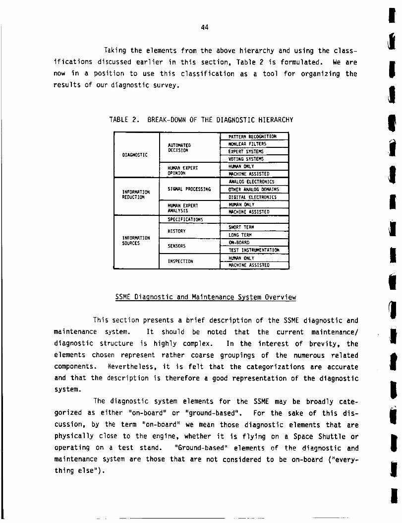
44
Taking the elements from the above hierarchy and using the class-
ifications discussed earlier in this section, Table 2 is formulated. We are
now in a position to use this classification as a tool for organizing the
results of our diagnostic survey.
TABLE 2. BREAK-DOWN OF THE DIAGNOSTIC HIERARCHY
DIA_OSTIC
INFORMATION
REDUCTION
INFORMATION
SOURCES
AUTOMATEDDECISION
HUMANEXPERTOPINION
SIGNAL PROCESSING
HUMANEXPERTANALYSIS
SPECIFICATIONS
HISTORY
SENSORS
INSPECTION
PAI'FERN RECOGNITION
NONLEAR FILTERS
EXPERT SYSTEMS
VOTING SYSTEMS
HUMANONLY
MACHINE ASSISTED
ANALOGELECTRONICS
OTHER ANALOG DOMAINS
DIGITAL ELECTRONICS
HUMANONLY
MACHINE ASSISTED
SHORT TERM
LONG TERM
ON-BOARD
TEST INSTRUMENTATION
HLI_IANONLY
MACHINE ASSISTED
SSME Diaqnostic and Maintenance SjKstem Overview
This section presents a brief description of the SSME diagnostic and
maintenance system. It should be noted that the current maintenance/
diagnostic structure is highly complex. In the interest of brevity, the
elements chosen represent rather coarse groupings of the numerous related
components. Nevertheless, it is felt that the categorizations are accurate
and that the description is therefore a good representation of the diagnostic
system.
The diagnostic system elements for the SSME may be broadly cate-
gorized as either "on-board" or "ground-based". For the sake of this dis-
cussion, by the term "on-board" we mean those diagnostic elements that are
physically close to the engine, whether it is flying on a Space Shuttle or
operating on a test stand. "Ground-based" el_m@nt_ nf th_ diannncflr aria
maintenance system are those that are not considered to be on-board ("every-
thing else").
I
i
II!iII!ii
lIIi
ImI
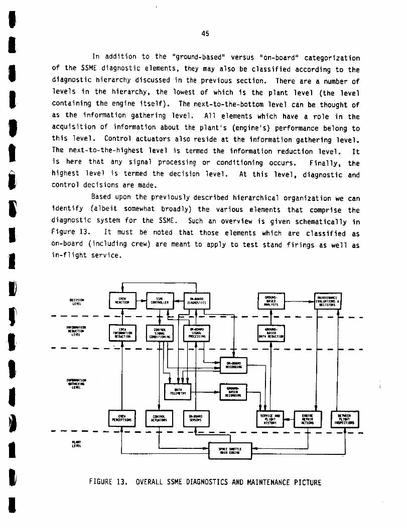
IIIIIIi|,|,
1
!iI'
1!JI
I
45
In addition to the "ground-based" versus "on-board" categorization
of the SSME diagnostic elements, they may also be classified according to the
diagnostic hierarchy discussed in the previous section. There are a number of
levels in the hierarchy, the lowest of which is the plant level (the level
containing the engine itself). The next-to-the-bottom level can be thought of
as the information gathering level. All elements which have a role in the
acquisition of information about the plant's (engine's) performance belong to
this level. Control actuators also reside at the information gathering level.
The next-to-the-highest level is termed the information reduction level. It
is here that any signal processing or conditioning occurs. Finally, the
highest level is termed the decision level. At this level, diagnostic and
control decisions are made.
Based upon the previously described hierarchical organization we can
identify (albeit somewhat broadly) the various elements that comprise the
diagnostic system for the SSME. Such an overview is given schematically in
Figure 13. It must be noted that those elements which are classified as
on-board (including crew) are meant to apply to test stand firings as well as
in-flight service.
O(C ,SIOII
L(lffL
llIT_llOll
UM_?IOIIL[VI[L
IlPmIMT 1011IATN(IIIm
L['_L
l.LH,-_*,
I_riJ ITIOI |
PLAIT
i •
I ..,I I,.,
TLEWL
FIGURE 13. OVERALL SSME DIAGNOSTICS AND MAINTENANCE PICTURE
I

46
Information Gathering
There are two on-board elements which provide the function of data
acquisition: crew perceptions and on-board sensors. The crew perceptions are
those observations of the flight crew on the Orbiter, and the support staff
during test stand engine firings. These observations are results of the
physical senses and should not be confused with information presented to the
crew by the diagnostic subsystems.
A number of on-board sensors are used primarily for control pur-
poses. The remaining sensors are dedicated to diagnostic functions. Some of
the control related sensor outputs are also used for diagnostic purposes.
Aside from the data acquisition function, there are on-board ele-
ments for data telemetry and data recording. Nearly all sensor outputs are
ultimately telemetered for ground-based analysis. A number of these data are
also recorded on-board the Orbiter.
On the ground-based side, a large amount of diagnostic data comes
from between-flight inspections. Data acquired by on-board subsystems are
ultimately integrated with the results of ground-based inspections and engine
repair actions to establish the engine flight and service history. This his-
torical data represents a valuable information pool for detailed analysis.
Information Reduction
All of the data, whether acquired by sensor, observation, or between
flight inspection must be reduced to a manageable set of features so that the
appropriate diagnostic or control decision may be quickly and accurately made.
Sensor data is characteristically reduced using signal processing techniques
such as time integration or low-pass filtering. Observations and inspection
results are typically reduced by the inspection specialists through the use of
heuristics.
Diagnostic Decisions
The on-board diagnostic subsystem uses a basic form of pattern
recognition. A table of "red lines", dynamically adjusted for changes in the
!
!1!!
!il!|
!!1!
!t!
I
I
|I
i
I
Ii _
i
I
!
I
I
47
engine's operational modes, is employed to flag potentially dangerous condi-
tions and dictate responses. Similarly, the crew reactions represent a human
pattern recognition resulting in well practiced responses.
Currently, the ground-based analysis employs an analytical model of
the engine combined with heuristic-based decisions to identify potential
trouble spots. This information is used to some degree to direct the between-
flight inspections, and aids in the maintenance evaluations and repair
decisions.
\
Summary /
This section has presented a high level overview of the SSME
diagnostic and maintenance system. The various diagnostic and maintenance
elements as well as their interactions (or possible interactions) have been
described and are depicted in Figure 13. The intent of the state-of-the-art
diagnostic survey is to identify possible techniques to improve the per-
formance of those elements and/or to improve the quality of their interconnec-
tions.
Survey Findings
This section presents the significant findings and highlights of the
state-of-the-art diagnostic survey. These findings are broken down into three
major application areas:
1. Liquid-fueled rocket engines,
2. Aircraft,
3. Non-aerospace industries.
Within each application area, the findings are further organized
according to the hierarchical classification discussed in the previous
sections.
Liquid-Fueled Rocket Enqines
The principal sources of information for this part of the survey
were rocket engine manufacturers, instrumentation vendors, Battelle experts,
and NASA reports.
I
48
The SSME is unique in that is the first truly reusable rocket engine
not on an experimental vehicle. This fact, combined with a design which
allows for smaller error margins than previous rocket engines, has dictated a
much more comprehensive diagnostic and maintenance philosophy than any of its
predecessors.
Data Acquisition. The vast majority of the sensing and instrumenta-
tion techniques are based upon well-seasoned approaches. In the case of
on-board devices, such well-established transducers as thermocouples, pressure
sensors, accelerometers, etc. are typically used. The data from these trans-
ducers are usually telemetered for ground-based analysis. Historically, manu-
facturers have not had a great deal of confidence in on-board instrumentation.
Rocketdyne is currently under contract with NASA to develop new instrumenta-
tion as a part of an advanced condition monitoring system.
Ground-based inspections are characteristically manual in nature.
Some instruments such as mass spectrometers have found application in the iso-
lation of gas leaks. Some new techniques for data acquisition have been pro-
posed and/or are under development, but none of those are yet considered to be
mature products.
Signal Processinq. Because of the basic nature of the diagnostic
systems employed on prior rocket engines, minimal on-board signal processing
techniques were used. The techniques used are basic in nature and have as
their objective the enhancement of the signal-to-noise ratio or sensor sig-
nals. Ground-based analyses of telemetered data characteristically employ
more sophisticated approaches.
Diagnostic Techniques. The sophistication of the diagnostic techni-
ques used on-board previous rocket engines has been minimal. The most common
real-time monitoring technique was based upon the violation of limits or "red
lines". Post-flight analyses, were usually more thorough, relying on tools
such as computer simulations.
Hiqhlights. Items of particular interest which were obtained during
the liquid rocket engine portion of the survey include:
I
|!
!
iI
!
i
!I
I
!f_
!
!
I
!
I
Ii
Ii
1
!i,
!
!
II
II
!
!l
II
49
Awareness of Need for Diagnostics. All of the manufacturers of roc-
ket engines that were interviewed (Rocketdyne, Pratt and Whitney, and Aerojet)
indicated an awareness of the need for comprehensive diagnostics on reusable
engines. Rocketdyne, due to its involvement with the SSME, has already
embarked on the development of a comprehensive condition monitoring system.
Both Aerojet and Pratt and Whitney intend to develop such systems on future
engine programs.
Current SSME Diagnostics. The engine monitoring system currently
employed on the SSME has been successful from the standpoint of crew/vehicle
safety. However, it is labor intensive and does not lend itself well to the
quick turnaround objectives of the STS program. The on-board diagnostics are
based upon violations of a series of safety limits ("red lines") some of which
are dynamically allocated. The on-board sensor set includes the following:
• temperature - resistive temperature detectors, thermocouples
• pressure - strain gauge, piezoelectric
• tachometer - magnetic pickup
• position - potentiometers, RVDT, LVDT
• vibration - piezoelectric accelerometer
• flowmeter - turbine
• calorimeter - thermopile
• radiometer - foil.
These sensors are considered by Rocketdyne to be adequately reli-
able. Data from some of these sensors are telemetered for ground-based
recording at 20 millisecond intervals during engine firings. The ground-based
portion of the diagnostic system is centered around a series of routine and
periodic inspections. The routine inspections include the following:
• external inspection
• internal inspections - HPFTP, HPOTP, MCC
• leak tests
• automatic/electrical checkotlts.
Borescopes are used for some of the internal inspections. Instru-
mentation required for leak tests includes flowmeters and mass spectrometers.
The periodic inspections involve the removal of either the HPOTP, HPFTP, or
both. During this activity turbine blades are inspected using optical
!
50
microscopy, and the respective preburner sections are inspected visually and
with concentricity gauges. In addition to the physical inspections of the
various engine components, the recorded flight sensor data is reviewed to
identify anomalies. The results of this review are communicated to the
inspection team when any action is deemed necessary.
Future SSME Condition Monitoring System. Rocketdyne is currently
under contract with NASA LeRC to develop an advanced engine condition moni-
toring system. The first phase of this study involved an analysis of failure
reports for a number of liquid-fueled rocket engines, including the SSME, J-2,
H-l, F-l, RS-27, Thor, and Atlas. The failure reports were reduced by succes-
sive screening and the resulting reports categorized into sixteen general
failure types.
• bolt torque relaxation
• coolant passage splits
• joint leakage
• hot-gas manifold transfer tube cracks
• high torque
• cracked turbine blades
• failure of bellows
• loose electrical connectors
• bearing damage
• tube fracture
• turbopump face seal leakage
• lube pressure anomalies
• valve fails to perform
• valve internal leakage
• regulator discrepancies
• contaminated hydraulic
control assembly.
Sensors were subsequently evaluated based upon their ability to aid
in the detection of the sixteen failure groups. An implicit philosophy during
this selection process was that one sensor (or group of sensors) would be
dedicated to each failure mode. A number of state-of-the-art and novel con-
cepts were identified. The sensors selected from those concepts were:
• fiberoptic deflectometer
• optical pyrometer
• isotope wear detector
• tunable diode-laser spectrometer
• ultrasonic thermometer
e optical tachometer
• ultrasonic flowmeter
• digital quartz pressure sensor
• holographic leak detector
• thermal conductivity leak detector
e exo-electron fatigue detector
• connector continuity checking
• particle analysis.
!
!i
i
I
,!|l
IiIi
Iii1!,II
!I!
I
I
II
Iil,
II
i
!III
51
Ultimately, the first three of these concepts were identified for
development and testing. This program is currently in progress. Another of
the sensors mentioned above, an ultrasonic flow meter, was tested during an
NSTL test firing. Because of problems arising from the sensor mounting, a
duct rupture occurred precipitating a catastrophic engine failure.
In addition to the identification of applicable sensors, the study
identified and evaluated the required signal processing techniques for use
with sensors to isolate the various failure modes. These techniques are:
• amplitude histogram
• RMS histogram
• filtered histogram
• cross correlation
e transfer function
• product histogram
• ratio histogram
• differentiated histogram
• phase diagram histogram
• time profile
• power spectrum density
• integral over threshold
• RPM profiles
e Cambell diagram
The various instrumentation vendors interviewed provided information
regarding many of the currently implemented SSME and aircraft test programs.
However, little information was obtained regarding new or novel instrumenta-
tion concepts.
Ultrasonic Doppler Vibration Sensor. Under contract with NASA MSFC,
Battelle's Columbus Division developed a shaft vibration sensor and success-
fully tested it on a J-2 rocket engine. The sensor was of a non-invasive
nature and determined the velocity of shaft vibrations by measuring doppler
shifting from reflected ultrasonic waves. Although a success, this sensor was
never developed further or utilized.
Aircraft
Sources for this part of the survey included interviews with experts
from the military, commercial air carriers, airframe manufacturers, engine
manufacturers, and instrumentation vendors. Information was also gathered
from literature and interviews with Battelle experts.
!
52
Aircraft engines and their diagnostics have received considerable
attention over the years. This attention is due to a number of factors,
including the military's emphasis on weapon system availability, the civilian
air carriers' push to minimize maintenance costs, and the FAA's desire to
assure safety and reliability. Consequently, this part of the survey yielded
a good deal of relevant information.
The current diagnostic/maintenance philosophies in the Air Force and
the civilian air carriers are similar. The Air Force is attempting to estab-
lish a policy termed "retirement for cause". This concept is most easily
described as an interactive preventative maintenance program. Component
failures are carefully analyzed and accurate life indicators are derived for
the engine components. The components will then be replaced only when a com-
ponent is deemed to have degraded sufficiently that it will not last until the
next periodic maintenance cycle.
The air carriers have a slightly different approach to maintenance.
Given the need to reduce ground time and keep the aircraft flying as much as
possible, a modified life limit approach to maintenance seems to prevail. An
engine is used until a component failure occurs, albeit in some cases an inci-
pient failure, or until life limits dictate a scheduled repair cycle. If the
engine is being repaired after a component failure, additional components
which would exceed their life limit prior to the next scheduled repair cycle
may be replaced.
Both the military and the commercial carriers employ a multi-tiered
maintenance structure. The first level is that of the flight line at which
major modules are replaced. A second level is responsible for troubleshooting
the modules that have been replaced so that they may be quickly placed back in
inventory. The third (ultimate) repair level is that of the specialized
shops. This level may also include the equipment vendors. Here the damaged
components are repaired and returned to the inventory of good parts.
Data Acquisition. Commercial aircraft engines all come equipped
with an array of accelerometers, temperature sensors, flow meters, pressure
transducers, and tachometers. The presence of some of those transducers is
due to FAA requirements placed on the manufacturers. While all of the air-
lines use the majority of the installed sensors, there has been some mistrust
of the accelerometers. Historically, they have experienced high false alarm
_j
II
II
nIii
IIIIII
!III
53
rates. As such, at least one airline removes them upon receipt of new
engines. The sensor manufacturers insist that the current generation of
sensors exhibit high reliability. Their claims seem to be substantiated by
the number of airlines that do use the entire sensor package for sophisticated
analyses such as trending.
Military aircraft engines usually carry many of the same transducers
as commercial engines. They serve both control and diagnostic purposes.
In the area of ground-based test, visual inspections, borescope
inspections, x-ray checks, eddy current checks, and oil analyses all find
application. Some sophisticated instrumentation systems are employed to
acquire data from engines in test cells. Temperatures, hot-gas flows and
pressures, and other similar data are gathered for off-line analysis.
Siqnal Processing. The signal processing employed for data from
on-board sensors is centered around the enhancement of signal-to-noise ratios.
Techniques such as low-pass, high-pass, and band-pass filtering are common
place. Features are sometimes generated using straight-forward approaches
such as integrating acceleration signals to derive velocity information.
Ground-based instrumentation employs similar signal processing approaches.
Diagnostic Techniques. The most common approach employed for
on-board jet engine diagnostics relies on a table of limits. When a limit has
been exceeded, the appropriate alarm is signaled and the response, if any,
initiated. Recently, this approach has been extended or supplemented by some
carriers who perform limited on-board trend analysis. Data gathered by
on-board sensors are recorded at regular intervals (ranging from several
seconds to several minutes). Trends are calculated in order to estimate when
the measured parameters will exceed their "red lines". This estimate may be
modified to allow for changes in the rate of degradation. Some air carriers
are now relying on information from ground-based trend analyses to con-
veniently schedule engine repair.
One diagnostic technique used by both the military and the civilian
air carriers merits discussion. This technique is referred to as "gas path
analysis". Developed and popularized by Hamilton Standard, the approach
involves the optimal estimation of the state, and subsequently the health, of
jet engines. In practice, a mathematical model is developed which represents
IJ

54
a simulation of a particular engine. Sensor data are then used as a gauge for
the optimal adjustment of the model parameters. When those parameters exceed
acceptable limits, a failure is declared.
At Kelly Air Force Base, the Air Force uses such a system for test
cell analysis of engines. TWA has also recently purchased such a system from
Hamilton Standard. In addition, TWA has initiated a program whereby sensor
data is telemetered from their latest generation of aircraft, and a quasi-
real-time analysis is performed to assess engine performance. The air
carriers rely heavily on an integrated system where in-flight data is analyzed
and used in conjunction with ground-based test results to plan maintenance
actions.
An on-going research and development effort is focused on the
concept of an expert system (artificial intelligence based computer program)
for jet engine diagnostics. This concept is based on the transfer of human
expertise to the expert system computer program. Although these systems are
maturing very rapidly, they are not yet considered to be off-the-shelf.
Hiqhlights. Items of particular interest which were obtained during
the aircraft portion of the survey include:
USAF Retirement for Cause. The USAF is in the process of imple-
menting a maintenance policy referred to as "retirement for cause". In short,
this policy requires that an experimental analysis be performed on each batch
of engine components in order to accurately understand and predict the life
limits in the presence of the potential failures. For example, the level of
propagation that a crack in a turbine vane must attain before failing will be
empirically determined. Once these life limits are known (or at least esti-
mated), the engine monitoring systems and periodic inspections are used to
track engine component failures. Only when the life limits are approached are
the faulty components replaced.
USAF On-Board Diagnostic System. An on-board engine monitoring
system similar to the AIDS (see below) was experimentally implemented on five
tactical F-15A aircraft (FIO0 Engines). The parameters monitored were:
!
!iiII
II!!l1lifII
I,I
aIf|ilI

ltl
!!!
!
I!
IIIIiiII
!
!
|,
!
I
55
• augmentor fuel pump discharge pressure
• augmentor permission fuel pressure
• burner pressure
• fan/core mixing pressure
• fan exit duct pressure
• fuel pump boost pressure
• fuel pump inlet pressure
• fuel pump discharge pressure
• main breather pressure
• number four bearing scavenge
pressure
• rear compressor variable
vane pressure
e fuel pump inlet temperature
• main oil temperature
e compressor exit static
temperature
• fan exit duct temperature
• diffuser case vibration
• inlet case vibration
• power level angle position.
The on-board data acquisition system monitored these parameters and
subsequently transferred the data for ground-based analysis. Such analyses,
in conjunction with ground-based tests were used as the basis for a main-
tenance program. On the whole, the experiment was considered to be
successful.
Experience with Commercial Carriers. Three domestic air carriers
were interviewed in addition to making a review of literature describing some
of the maintenance policies of European airlines.
Nearly all carriers utilize a variation of the aircraft integrated
data system (AIDS). This data system was specified by ARINC and has the
following attributes:
• diagnostic information is centralized
• some data is available for in-flight analysis
• data is recorded on a cassette tape for
analysis.
later ground-based
A number of carriers have implemented engine monitoring systems
which are also integrated with the AIDS. In these systems, important engine
parameters are monitored in-flight such as gas pressures and temperatures,
fuel flows, rotor velocities, lubricant temperatures, and vibrations. Engine
condition reports are available during flight to the flight engineer for
short-term trending analyses. Long-term trending is performed using the AIDS
data tapes during ground-based analyses.
56
In addition to the engine monitoring systems, ground tests andinspections are used to identify failures and trends. Ground-based inspec-tions may include:
• visual inspection
• borescope inspections
• x-ray checks
m eddy current checks
• spectrographic oil analysis
• ferrographic oil analysis
The general consensus in the European air carrier community is that
such sophisticated diagnostic and maintenance programs are cost justified.
The domestic air carriers are not quite so aggressive. TWA, however, has a
maintenance and diagnostic program which is very much along the lines of the
European carriers. United Air Lines on the other hand, seems to employ a more
conservative, people intensive approach to maintenance and diagnostics.
Gas Path Analysis. Hamilton Standard Division of United Technolo-
gies has been marketing a computer software package called Gas Path Analysis.
This software relies upon a linearized mathematical model of a specific jet
engine to estimate the performance characteristics of the engine's constituent
modules using measured input parameters such as temperatures, pressures, spool
speeds, and fuel consumption. The program also estimates the performance of
the various sensors that are used to acquire the data used in the analysis.
The mathematics of gas path analysis is based on the premise that it
is possible to linearize any thermodynamic cycle model by deriving matrices of
influence coefficients which relate deviations in measured parameters and com-
ponent performances to coefficients describing component faults for each of
the engine's operating points. The equations solved are:
A=HX+B
Y = Ge Xe
Xe
where X = (_-_) and H = (HelHs)
The significance of the various variables is as follows:
• Z is a column vector of measurement deviations or deltas
• Y is a column vector of performance deltas for the engines' con-
stituent modules
!i
i
i
I
II1
I
iit
iI
!iIi!

I
I
i
i
I
I
I
I
I
I
I
I
i
I
II
I
!
!
57
• Xe is a column vector of engine fault deltas
• Xs is a column vector of apparent sensor errors
• He and Ge are the matrices of coefficients derived from the
engines' mathematical model
• Hs is a matrix of sensor fault coefficients
• e is a random vector denoting sensor non-repeatability.
The dimensions are such that there is an over-specified set of equa-
tions which are a result of analytical redundancy in the measured parameters.
It is also this fact which allows the determination of sensor errors as well
as engine component malfunctions.
A number of air carriers use this technique for ground-based
analysis. Some European carriers and TWA use the gas path analysis program
for analysis of flight data. Other carriers and the USAF use it only for test
cell analysis of engine performance.
Sensors and Instrumentation Development. The area of sensor devel-
opment receiving the greatest amount of attention for flight applications is
that of fiber optic sensors. These sensors are especially desirable from the
standpoint of weight and noise immunity. At this stage of development, how-
ever, the fiber optic connector technology is not sufficiently robust to allow
widespread use on flight engines. A recent NASA study has examined applica-
tions for fiber optic sensors such as:
• rotary encoders
• optical tachometers
• rotor blade tip clearance
• optical temperature sensors (pyrometers).
Optical pyrometers have also been used in experiments to accurately
determine turbine blade life. Solar Turbines Incorporated has provided such
instrumentation for a number of these experiments. Optical clouding due to
the presence of combustion products has been the principal operational draw-
back of this type of instrumentation.
In the more general area of data acquisition, a number of instru-
mented engine core test programs have been carried out. An off-the-shelf sys-
tem for telemetering data from an engine rotor is available from Acurex Cor-
poration. These systems are not considered to be sufficiently robust for
flight applications.
/
58
Expert Systems. There are at least two programs underway for the
development of rule-based expert systems for jet engine diagnosis. On the
military side, the Air Force has been funding such a development at General
Electric. In the commercial sector, Boeing has also been developing an expert
system for jet engine diagnosis.
Non-Aerospace Industries
Information sources for this part of the survey included interviews
with experts in fields ranging from medical electronics to transportation sys-
tems. In addition, interviews were conducted with Battelle experts and rele-
vant publications were reviewed.
In general, the industrial sector has been somewhat slow in recog-
nizing the potential of machine diagnostics, but recently, there has been an
increasing emphasis in this area. The motives for this interest are varied.
For example, NRC regulations have had a strong influence on the nuclear power
industry while customer support issues have had an impact on the use of diag-
nostics in the automobile industry. Whatever the motives, some interesting
techniques have resulted which may ultimately be of value to the SSME program.
Data Acquisition. In the area of transducers, most industries have
embraced the proven sensors, e.g., accelerometers, thermocouples, etc. The
manufacturers of those devices have been developing more reliable and "rug-
gedized" transducers and recognize that their sensors will be located in pro-
gressively more hostile environments.
In terms of sensing concepts, a number of techniques in development
or use merit discussion. These concepts are described in the following
paragraphs.
In the nuclear power industry, a device known as a miniature
accelerator or MINAC has been developed for radiographing pump housings. The
device is placed inside the housing and photographic film is placed around the
outside of the housing. Once activated, the MINAC generates radiation that
penetrates the pump and exposes the film--from the inside-out. This device
has simplified a difficult imaging problem.
IIitgI
iI
!|
,iI
III,I
i
1iI
I
!I
I
I
!
|
II
!
I
!
!
i
!
59
For the conventional power industry, Solar Turbines Incorporated is
under contract with the Electric Power Research Institute to instrument a gas
power turbine with an optical pyrometer. The pyrometer is positioned to scan
the passing turbine blades and provide measurements leading to accurate pre-
dictions of the blades' life.
A number of novel fiberoptic-based sensors have been under develop-
ment. An example of this is the laser-doppler-velocimeter (LDV) which mea-
sures the velocity, not speed, of moving material. The material being mea-
sured can be a solid or a fluid. Because of its optical nature, the informa-
tion can be communicated from the moving medium to the sensor by optical
fibers. This sensor is already finding application in the manufacture of
synthetic fibers.
A new class of semiconductor devices for measuring the presence of
various elements has been under development. This device is called an ion
selective field effect transistor (ISFET). These devices have been proposed
for measuring such parameters as hydrogen concentrations in gases, and glucose
levels in human blood. ISFETs have certain stability problems that have not
as yet been resolved.
Cooperative sensing schemes are finding increased usage. The prin-
cipal behind this concept is not new: the design of the system or component
to be examined is altered so as to provide a clear, unmistakable signature
which is easily monitored. Putting a tracer in a gas to measure concentra-
tions and flows represents a well developed application of this technique. In
a more recent example, bearing balls where magnetized to allow the monitoring
of their behavior by simple magnetic field sensors.
For the storage of performance data, the memory card, an extremely
portable device, is gaining popularity. This device is comprised of a micro-
computer and nonvolatile data memory in a very small package (typically the
size of a credit card). Memory cards, because they are inexpensive and port-
able, can permit the highly accurate tracking and monitoring of modules and
components as they progress through the repair cycles. Unfortunately, the
storage capacities of the data memory are still limited.
Vibration monitoring is common in numerous industries ranging from
petrochemical plants to paper mills. For example, at Exxon's petrochemical
plant in Baytown, Texas much of the machinery is continuously monitored using
a minicomputer and on-board accelerometers. The signal levels of the
!
60
accelerometers are analyzed to determine trends. Based upon such trends,
maintenance can be optimally scheduled. In this same plant, such phenomena as
pump cavitation were also detected by more careful analysis of the accelero-
meter signals. However, the ability to gather this additional information has
not been integrated into the monitoring system.
Siqnal Processinq. In the realm of signal processing, the most
impressive developments have been in the area of hardware. Integrated cir-
cuits are now available which perform such functions as real-time digital fil-
tering or real-time Fast Fourier Transforms. A manufacturer of charge-
coupled-device (CCD) arrays, EG&G Reticon, also manufacturers semiconductor
devices which perform many of the filtering and analysis functions in the
discrete time analog domain. Prior to the availability of those devices,
these filtering techniques were only possible using digital electronics.
In the continuous time domain, a number of sensors have been devel-
oped for specific applications to perform filtering functions in a non-
electronic fashion. One well developed example of this approach is the use of
a tuned acoustic transducer for the monitoring of predetonation in GM automo-
bile engines. This approach was used by GM in a effort to minimize production
costs.
In the field of automated inspection systems a good deal of progress
has been made in image processing and image interpretation. Commercial sys-
tems are now available for the automated inspection of pieces on an assembly
line for manufacturing defects. Similar techniques have been developed for
the autonomous inspection of printed circuit boards. This area will likely
continue to evolve due to the recent successes.
Recent research in the human factors associated with display tech-
nology is directed toward the presentation of high level information, rather
than machine parameters, in a graphical format. In industries such as nuclear
power, the operators of the systems need diagnostic information in a high-
level and unambiguous format, thus, permitting the decisions to be made
quickly and accurately via human pattern recognition.
Diagnostic Techniques. The approaches used in the industrial sector
for making diagnostic decisions span the entire spectrum, from the simple
table lookup technique employed on most automobiles, to expert system computer
l
IIlI!I
IIil
I
l
ID
i
II
l
IIIiI
IIIIISIII
IIiI
61
programs for the diagnosis of failures in train locomotives. Of the informa-
tion gathered during this part of the survey, there are several concepts worth
mentioning. These make up the remainder of this section.
General Electric Corporation has developed an expert system (com-
puter program) for the diagnosis of failures on railroad locomotives. In this
approach, the computer program was written to reason and draw conclusions
based upon a set of rules. The set of rules is derived from interviews with
human experts in the area (that of repairing GE's locomotives). In operation,
the expert system guides the actions of a repair technician. This is only one
of several diagnostic "experts" that have been developed: Westinghouse's
Steam Turbines Division has developed a diagnostic expert system for steam
turbines. The Westinghouse program, moreover, identifies sensor malfunctions
as well as turbine component failures.
On-going research in the area of non-linear diagnostic filters pro-
mises to improve their performance by increasing sensitivity and reducing
false alarm rates. In one particular effort involving Case Western Reserve
University and Bailey Controls Division of Babcock and Wilcox, an industrial
heat exchanger will be the test bed for an improved non-linear diagnostic
filter. The benefits of such research efforts are likely to be incremental in
nature, but available in the relatively short term.
The commercial application of pattern recognition based upon statis-
tically derived and/or empirically determined features has been a reality for
a number of years. The benefits of this approach is that the computation
times for making decisions about a machine's performance can be very brief.
Other computationally oriented techniques, non-linear diagnostic filters and
expert systems, typically require substantially more time than pattern recog-
nition. Historically, most pattern recognition systems have been custom
tailored to the signatures of single specific machines, rather than, for
example, other identical machines. This shortcoming has been addressed
through the use of adaptive pattern recognition systems.
Vibration trend analysis is becoming a commonly used technique,
especially in industries such as petrochemicals and paper manufacturing. This
technique usually involves the monitoring of vibration sensors (most often the
integrated outputs of accelerometers) to watch for change. The rate of
increase is estimated, and repairs scheduled according to the estimated time
until a failure occurs.
I

62
Predictive diagnostics based upon ferrographic analysis of lubricant
has been a reality for a number of years. This technique is based upon the
gathering and analysis of wear particles to determine the mechanisms and
severity of wear. While there are machine mounted sensors available for auto-
mated ferrographic analysis, the most thorough analyses are performed off-line
using bichromatic microscopy.
Voting systems have been used to address anticipated failures (i.e.,
those failures that result from known component failure modes). However,
unanticipated faults due to such causes as design errors cannot be addressed
by voting systems. The more complex a machine, the greater is the likelihood
of latent design errors.
Recommendations
Given the nature of the SSME environment and maintenance structure,
several of the approaches and techniques identified in the previous section
are recommended. We will hold to the same organization that has been used
throughout this report. These recommendations are further summarized in
Table 3.
Data Acquisition
To the extent possible, those existing on-board sensors which have
experienced reliability problems, should be considered for replacement. As
existing sensors are continually improved for sensitivity and durability, they
should be examined and, as warranted, tested and considered for use on the
SSME. A sensor data base would be beneficial for both the $SME, and for
future rocket engine development programs.
The on-board sensors should be more effectively used. For example,
the accelerometers currently on the SSME are only used for the RMS values of
their outputs. There is undoubtedly a great deal of information available in
the higher frequency harmonics that is not being used. The full bandwidth of
all existing sensors should be recorded onboard and the data later used for
detailed ground-based analysis. It also may be possible to telemeter this
recorded data while the STS is on orbit.
I
I
I1IIi
!i
IIIIi
!I!i
I

II
!
63
TABLE 3. SUMMARYOF DIAGNOSTICS RECOMMENDATIONS
IDiagnostics
CategoryRecommendations
On-Board Ground-Based
IIIIIII
II
II
i
Data Acquistion
Signal Processing
DiagnosticTechniques
More Reliable Sensors
Increased Bandwidth
for Existing Acceler-ometers and Trans-
ducers (pressure,temperature, flow,
and speed)
Additional Conventional
Sensors
Extensive Data
Recording
Continued Developmentof:
Optical Pyrometer
Fiber Optic Deflecto-meter
Ultrasonic DopplerTransducer
Ultrasonic Flow
Meter
Improve S/N Ratios
by Spectral Filteringand Noise Cancellation
Analysis and Developmentof Pattern Recognition
Diagnostic System
Continued Development
of Isotope Wear Detector
Extension of Isotope
Wear Detector Conceptto Include Ferro-
graphic Analysis
Use of Tracer Elements
(Tritium or Sulfur
Hexafluoride) forLeak Detection
Image Processing+to Enhance
Borescope Inspections
Develop Gas Path
Analysis Model of SSME
Evolve Gas Path AnalysisModel to Include Non-
Linear Diagnostic Filter
Establish and Maintain
Integrated SSME Data
Base (diagnostic and
maintenance)
I
I
I
64
It is estimated that upwards of 85 percent of all failures are
intermittent in nature. Over the course of our survey, two approaches to the
isolation of intermittent failures were identified: marginal testing and
extensive logging. The use of marginal testing techniques on the SSME is not
feasible. Therefore, we recommend that extensive on-board recording of the
engine be performed. By analyzing this extensive amount of data, either on
the ground or on-board, intermittent problems may be identified and isolated.
In addition, the extra sensors required for such monitoring will augment the
analytical redundancy of the diagnostic system.
The sensors proposed by Rocketdyne for the monitoring of turbo-
machinery should be carried through to application. Specifically, the optical
pyrometer, fiberoptic deflectometer, and isotope wear detectors, will signi-
ficantly improve the information available on the health of the turbopumps.
In addition, the isotope wear detector program should be extended to encompass
ferrographic analysis. Numerous precedents suggest that this type of analysis
would be valuable for predictive diagnosis.
For ground-based inspections, we recommend that tracing elements
should be considered to aid in the detection of hydrogen and other fluid
leaks. It is felt that this would result in the simplified sensing apparatus.
Signal Processinq
For ground-based tests, image processing should be used to augment
certain inspection processes, especially the borescope inspections. It is
believed that such techniques could both improve the accuracy, and reduce the
time required for inspections.
For on-board instrumentation, more elaborate signal processing will
be required. Given the noise environment of the SSME, both spectral filtering
and statistical noise cancellation techniques could be used to provide
improved signal-to-noise ratios. High signal-to-noise ratios are essential if
the existing sensors are to be more fully utilized.
Diagnostic Techniques
In the arena of diagnostic techniques there are three recommenda-
tions, one for on-board diagnosis and two for ground-based analysis. The
!
!
l
III
i
1
l
I
I
i
I
i
I
I
I
I
I
I
!
!
I
I
!
i
I
III
!IIiI
65
principal purpose of the on-board diagnostics is to avert rapidly developing,
catastrophic failures. Because of the speed of diagnosis and level of
accuracy required, pattern recognition is the only realistic technique. To
increase the coverage and accuracy of the on-board diagnostic system, a
pattern recognition-based diagnostics should be considered.
For ground-based analyses, an effort to improve the analytical model
for the SSME should be undertaken. In conjunction with such a model, a non-
linear diagnostic filter should be developed. This effort might begin by
initiating a gas path analysis program, and improving the analysis on an
incremental basis. It may even be possible to run such a program in real-time
based upon telemetered data (given adequate computing resources). If the
system is sufficiently accurate, detailed trend analysis capabilities could
result.
Finally, a thorough and highly integrated data base should be estab-
lished to track and correlate information about engines and components.
Information from on-board sensors, ground-based inspections, repair actions,
and component histories should be included. Analysis of this data base must
be made highly interactive to be most effective. Ultimately, such a data base
could benefit the SSME maintenance staff, the operations staff, and the engine
component manufacturers.
!
66
(THIS PAGE INTENTIONALLY BLANK)
"o_,
I
I
I
!
II
I
!
j
t!!!!!!
!
67
SSME DIAGNOSTIC EVALUATION
The third task of the SSME study is intended to assimilate the out-
puts of the SSME failure data review and the diagnostics survey and to use
this information for evaluating the current $SME diagnostic system. The
principal objective of this task is to identify potential means for improving
the availability of high-quality, pertinent engine data. This information
will be used both in-flight and on the ground to assess the condition of the
SSME and its respective components. To accomplish this objective, an analysis
tool has been selected to perform a systematic examination of the diagnostic
information in the SSME. This tool (Failure Information Propagation Model)
and its initial application to an SSME component is described in this section.
Issues and Approach
To evaluate the overall SSME diagnostic system, the information
gathered during the failure data review and diagnostic survey must be inte-
grated and analyzed. At the outset of this evaluation task, the following
data were available:
• Results of the SSME failure data review
• Knowledge of the existing SSME inspection and maintenance process
• Knowledge of the current SSME sensors
• Information on sensor research and development underway for the
SSME
• Results of the diagnostic survey.
This information was believed to provide a solid foundation for performing the
required evaluation.
The first step in the analysis was to select the actual tool or
technique to be used. To facilitate selection of a suitable analysis method,
an overall approach was defined for the task. The approach adopted centered
on addressing several key diagnostic issues. These issues included the
following:
• What additional diagnostic information is available to the
existing SSME sensors?

68
• Are there any information rich test points on the SSME that
should be instrumented? If so, which sensors should be
considered?
• How can we optimize the placement of additional sensors so as to
minimize their total number and cost while maximizing their
information gathering potential and reliability?
Which _,_lrumentation research and development areas represent
the best investment relative to the diagnostic needs of the SSME?
The common denominator for all of the issues mentioned above is an under-
standing and characterization of the engine failure information and its flow
paths.
The major focus of the initial effort on this task was directed,
therefore, at finding a suitable means to represent the SSME failure informa-
tion and at developing a data format which could be easily manipulated to
address each of the above issues. The tool which appeared to satisfy all of
the proposed requirements was the Failure Information Propagation Model
(FIPM). The FIPM concept is discussed in the following subsection.
Failure Information PropaBation Model
The Failure Information Propagation Model (FIPM) is a technique
developed by the Battelle Columbus Division to qualitatively evaluate the
potential test points in a system. The objective of this qualitative evalua-
tion is to assess the information bearing value of each test point. The FIPM
basically divides the system under analysis into its principal components or
functions, describes the failure modes for these components, catalogs the
physical connections between the components, details the flow of failure
information through the various connections and groups the failure informa-
tion according to signalproperties. It must be emphasized at this point that
the FIPM models the propagation of failure information and not the failure
itself. The model assumes that the system being depicted is in a near-normal
state of operation. The failure information flow is described for the instant
of time immediately following a given failure.
The FIPM was initially developed to evaluate the factors affecting
copy quality in a photographic copy machine. This proprietary study was
performed for an industrial client. Due to the nature of the system involved,
III
i
II
III
il!
i
Il
I
Il
I

I
I
I
I
I
I
I
I
i
I
I
I
I
I
I
i
I
I
69
this analysis was primarily concerned with the electronic functions of the
device. Subsequent to this study, the FIPM was applied to an ion chamber and
a home furnace. All of this work preceded the FIPM's consideration for this
task. As a result of this early work, the FIPM has demonstrated the capa-
bility to adapt to a broad range of mechanical and electronic systems.
Three principal applications exist for the output of this model.
These applications are:
• Design of sensor systems for new devices or components
• Evaluation of existing sensor systems to maximize the information
yield
• Identification of sensor research and development needs to target
key diagnostic data.
These important features of the FIPM made it especially attractive for use in
the SSME diagnostic evaluation.
FIPM Example
The formulation of an FIPM must begin with the identification of the
modules (components or functions) that comprise the system being evaluated.
These modules may be piece parts, subassemblies, or subsystems depending on
the level of detail sought. In the case of a typical exhaust fan, which is
used here solely as an example, the constituent modules are subassemblies
which have been selected to illustrate a top-level FIPM. In the case of the
high-pressure oxidizer turbopump (HPOTP) FIPM which will be discussed later in
this section, the constituent modules generally are piece parts.
The modules selected to illustrate the FIPM concept for the exhaust
fan are the AC motor, the fan belt, the fan, the fan bearing, and the frame
which supports these components. These elements are shown in Figure 14. The
resulting model is very simple in that the AC motor actually has both elec-
trical and mechanical parts, the fan has both blades and a pulley for the
drive belt, etc. It is recognized that this model ignores many factors which
would be considered in a thorough engineering analysis.
The network of connections between the exhaust fan modules is
depicted in Figure 15. As indicated in this figure, the motor is mechanically
mounted to the frame and transforms electrical power into mechanical power
_.
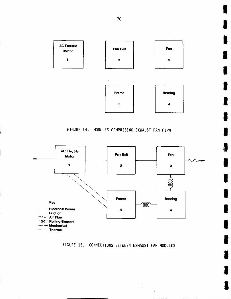
70
AC Electric
MotorFan Belt
2
Fan
Frame
5
Bearing
FIGURE 14. MODULES COMPRISING EXHAUST FAN FIPM
AC Electric
Motor
\ \ \\\
Key
Electrical Power
Friction
Air Flow
Rolling Element-- Mechanical
----- Thermal
\\\ \
\
Fan Belt
2
Frame
5
Fan
Bearing
FIGURE 15. CONNECTIONS BETWEEN EXHAUST FAN MODULES
H
I
I
II
I
III
I
!I
I
II
IIt
II

i
I
I
I
nI
i
i
I
I
l
l
I
I
I
II
i
71
through friction with the fan belt. The fan belt also is connected by fric-
tion to the fan. The fan and frame are joined through the bearing by means of
rolling elements. A thermal connection also exists, in normal operation,
between the AC motor and the frame. The final element in the network is an
air flow path out of the fan.
The failure modes of each of the exhaust fan modules is shown in
Figure 16. It should be noted that these failure modes do not include
mechanisms which are external to the module. Failures due to such outside
causes as fire, explosion, or mechanical damage are not considered. Events
such as fire in the fan motor also are not considered since these are actually
effects of more fundamental failure modes. It should be reiterated that the
FIPM is modeling the situation immediately following a failure and not the
longer-term effects and consequences of that failure.
The occurrence of any exhaust fan failure mode produces failure
information which can be detected externally to the component and which will,
in general, be transmitted to adjacent components. An assessment of the
failure information propagations for the exhaust fan example is shown in
Figure 17. It is interesting to note that, in this example, all of the
failure modes transmit failure information to all of the other modules. The
large amount of failure data which is available at any given connection in the
system is evident in this figure.
The failure information in the current example can be further cate-
gorized at each connection according to the type of measurement or sensor
required for detection. An open winding [1C] or breakage of the fan belt [2B]
could be detected by an ammeter on the electrical line. Similarly, binding of
the motor ilAl, a shorted winding lID], or dirt on the fan [3B] can be
detected by a voltmeter across the motor terminals. In Figure 18, the failure
information for each connection has been grouped according to the type of
measurement involved. This clustering of the failure information is the final
step in the development of the FIPM. Analysis of the data in the model can
now be initiated.
A sensor of the appropriate type would detect any or all of the
failure modes within a particular group. It would be necessary, therefore, to
provide additional information or to further process the signal to uniquely
identify any single failure mode. The process of determining the failure
signatures and respective sensor sets is highly detailed and has not been
undertaken for the exhaust fan example.
!

72
AC Electric Motor
1
A. Binding
B. Bearing Vibration
C. Open Wlndlng
D. Shorted Wlndlng
\\\
\\ \\
Key
Electrical Power
Friction
Air Flow
Rolling Element-- Mechanical
----- Thermal
\\
\ \\
_.\\
_."
Fan Belt
2
A. Slipping
B. Breakage
Frame
5
Fan
3
A. Blade Damage
B. l_rt
Bearing
4
A. Wear
B. Pitting
FIGURE 16. ADDITION OF FAILURE MODES TO EXHAUST FAN FIPM
1-A.B,C.O
2-A,B
3-B
Key
AC Electric Motor 1-A,B,C.O
1 2-A,B3-B
A. Binding
B. Bearing Vibration
C. Open Winding
0. Shorted Winding
\\ \\ 1-B
\
1-A,D_ \ 4-A• \
\
Electrical Power
Friction
Air Flow
J'0"F0_ Rolling Element--- Mechanical
---- Thermal
Fan Belt
2
A. S,_ngB. Breakage
Frame
5
1-A,C,D
2-A,B
3-A.B
4-A,B
3-A4-A,0
Fan
3
A. Blade DamageB. DWt
3-A4-A,B
Bearing
A. Wear
B. Pitting
1._,c,o2-A,B
3-A,B
FIGURE 17. FAILURE INFORMATION ASSOCIATED WITH EXHAUST FAN CONNECTIONS
I
I
i
II
I
1I
II
III
I

I
I
I
I
I
I
I
l
I
I
I
I
I
I
I
I
I
I
73
[IC] [1A, ID.3B
I_B.2A){2B]
Key
--- Electrical Power-- Friction
Air Flow
Rolling Element--- Mechanical---- Thermal
AC Electric Motor[1A,1C,1D,3B]
1 [2B) [1B,2A]
A. Blndlng
B, Bearlng Vlbrallon
C. Open Wlndlng
O. Shorted Winding
\\\ _[1B,2A,4A]\ \
[1A.wlx-x, \• \
_.. \\
\
Fan Belt
2
M. mlpp_gB. Breakage
Frame
5
[1A.1C.1D,3B]
[2A,3A,4A]
[2el [4B]
[3A,4A][4B]
Fan
3
A. Blade DamageB. D6rt
_ 13A,4A]I4B]
Bearing
4
A. Wear
B. Pitting
[1A,lC,IO,3B]
[2A,3A]
FIGURE 18. FAILURE INFORMATION GROUPED BY SIGNAL TYPEFOR THE EXHAUST FAN FIPM
High-Pressure Oxidizer Turbopump FIPM
The high-pressure oxidizer turbopump (HPOTP) was selected as the
initial SSME component for evaluation using the FIPM. An HPOTP FIPM was
graphically constructed using the steps outlined in the preceding example.
The resulting model was quite large due to the complex nature of the HPOTP. A
large portion of the initial representation also was color coded for ease of
interpretation. Due to both of these factors, the initial HPOTP FIPM is
unsuitable for inclusion in this report. An attempt will, however, be made to
describe the significant features of this model and the subsequent analysis
which was performed. The version of the FIPM which will be described in this
section is no longer the baseline configuration for the HPOTP. The reasons
for this situation will be discussed. The revised FIPM approach which is
currently being used is outlined in a subsequent subsection.
I

74
The original HPOTP FIPM had the following features:
• 46 modules
• 100 module failure modes
• 59 connections
• 2248 failure information propagations.
A small black and white excerpt of this FIPM is shown in Figure 19. A key for
this graphic is included as Figure 20. All of the data comprising the FIPM
was displayed on the graphic representation.
Subsequent to the development of the HPOTP FIPM, a preliminary
analysis of the HPOTP failure information was performed using a failure infor-
mation matrix. A portion of this matrix is shown in Figure 21. In this
matrix, the rows represent connections (test points) between modules. The
columns correspond to specific module failure modes. The data entered in the
matrix at the intersection of a given row and column is the failure
information types associated with the designated failure mode which can be
detected at the designated connection. This matrix was used to develop a
preliminary set of test signature equations for the HPOTP.
i 13
BEARING #3 1
INNER RACE
b. Pitting
I
[RAV] Ib, ]9a _ [STF]
[CAV] 2a, 21b _ [REW_
[RUB] 2b, 2Ia [REP]
14
13-15a, 13-15b13-15a13-15b
J._._P2:c_T2i: ..... __ ..•..-_--.-.-I I------_
AXIAL SPRING
CARTRIDGE
a. Wear: Friction
BEARING #3BALLSm a. Wear
b. Pitting
I
[RAV] ib, Iga _ [STF] 13-15a, 13-15b
[CAV] 2a, 21b _ IREWI 13-15a
[RUB] 2b, 21a LREP] 13-15b
15
OUTER RACE
a. Wear
b. Pitting
I
FIGURE 19. EXCERPT FROM INITIAL HPOTP FIPM
II
I
II
I
i
I
I
II
I
tI
F ,!
I

I
I
I
I
I
I
I
I
I
I
I
I
I
I
i
I
I
i
75
+
I +" l+'t
COUPLING TYPE
, Solid
-- ... --. Liquid
O 0 e e • • o • • • Gas
==,,,==,O,=,_,O_u,O_-,,- Liquid and Gas
Thermal
FAILURE SIGNAL TYPES
[RUB] Rubbing[CAV] Cavitation[CRK] Cracking[REW] Rolling Element Wear[REP] Rolling Element Pitting[RAV] RPR Associated Vibration[IMP] Impact[LFP] Low Flow or Pressure[STF] Stress-time fatiglm Candidate[ERO] Erosion[HLT] High Local Temperature
COUPLING NODIFIER
Q Oxygen
Q Heli_
Q Common Part
:I Unanticipated Coupling
Spring
Rolling Element
Lubricant
FIGURE 20. KEY FOR INITIAL HPTOP FIPM
The test signatures were formulated by marching through the columns
of the matrix. For each column, the rows were examined to determine where
failure information resided. The rows also were scanned to identify other
failure data present at the connection which exhibited the same signal
characteristics (i.e., high temperature, low pressure, etc.). By careful
evaluation of the matrix, it was possible to determine sets of signals which
could be used to uniquely identify specific failures. Some examples of the
initial results included:
• Failure mode 1B = rpm associated vibration @ test point 34 OR
= rpm associated vibration @ test point 36 OR
= rpm associated vibration @ test point 38
• Failure mode 2A = cavitation @ test point 5 AND NOT
cavitation @ test point 1
I

76
=11.,. w_
= ;
I
ORIGIX_-P_'_ IS I
I
_3
I
I
Ze_
OI--
z
oi,
x
I,.--
o
_rev,0
z
I
II
Ii
II
I
II
III
Il

77
i
I
I
I
I
I
I
• Failure mode 2B OR
• Failure mode 3A OR
• Failure mode 5c : rubbing @ test point 4.
No attempt was made to determine a unique signature for certain classes of
failure modes. In cases such as the turbopump bearings, it is not necessary
to know which particular bearing is bad. An indication that any of the four
bearings is experiencing degradation is sufficient cause to remove the turbo-
pump from the engine and overhaul the bearings.
Subsequent efforts to specify a set of diagnostic sensors which
would target all of the high-priority HPOTP failure modes, as identified in
the SSME failure data review, encountered difficulty due to the need for addi-
tional data. The model, as constructed, did not have sufficient detail to
adequately describe the failure signals. It was determined that specifying
high temperature was insufficient without some sort of associated range. This
initial application of the FIPM methodology to a complex mechanical system had
also demonstrated the need for more formal definitions and standardized
development rules. The definitions and development rules had previously been
instituted on an ad hoc basis as the need arose. A decision was reached to
restructure the HPOTP FIPM based on a more formal development methodology.
Revised FIPM Methodoloqy
The revised FIPM methodology was prepared by the originator of the
FIPM concept with major inputs provided by the participants in the initial
FIPM activity. A number of definitions and rules resulted from this process
which will be documented at a later date. The definitions, in general, con-
cerned the types of physical connections, failure modes, signals, and signal
parameters which can be used in constructing the FIPM. These definitions have
been made with respect to fundamental physical properties and laws. Their
intent is to reduce the number of arbitrary and possibly confusing choices
which must be made during model formulation. The rules relate to the handling
of certain situations which otherwise might be ambiguous.
It was also decided that the new FIPM procedure should be imple-
mented in a data base format. This step was necessary to accommodate the
large amounts of information which were projected for the SSME models. After
I

78
consultation with the technical staff at both NASA Headquarters and NASA MSFC,
Digital Equipment Corporation's Datatrieve data base management system was
selected for use in this application. This system was chosen in large part
because of its availability at NASA MSFC and the substantial base of experi-
ence which existed at both Battelle and at MSFC.
The revised FIPM methodology still uses a graphical representation
of the system. However, the failure information propagations are no longer
shown on this diagram. The graphical representation includes only the
modules, module failure modes, and the connections between the modules. All
of this data is used extensively during the propagation of the failure infor-
mation throughout the system. The information displayed on the FIPM diagram
is also stored in the data base along with the failure information propa-
gations. The data base also allows additional descriptive data to be stored
concerning the modules, module failure modes, and connections between the
modules. Incorporation of this data would have been impossible with the
original graphic model.
FIPM Status
The revised FIPM methodology has been completed. It is recognized,
however, that any procedure such as the FIPM must always undergo some expan-
sion and modification. The development methodology does allow for flexibility
but such changes should be made only after careful consideration of all the
consequences. The methodology will be documented in the final report covering
the on-going phase of this study.
The software associated with the FIPM data base is currently under
development. This software will be documented at the time of delivery to NASA
MSFC. MSFC will be provided with a magnetic tape containing all of the input,
modification, and listing procedures developed. All SSME FIPM data generated
during the conduct of this study also will be transferred to MSFC.
The revised HPOTP FIPM presently is being formulated in parallel
with the development of the FIPM data base software. The completed HPOTP FIPM
will be documented in a separate technical report. This report will include
the FIPM graphic representation and listings of all the HPOTP information
stored in the data base.
I
II
llII
I
II
l
II
I
III
II
79
The process of implementing the data base and producing the HPOTP
FIPM is a highly interactive situation. The data definitions associated with
the various data files affect the information which must be generated for the
HPOTP. Likewise, situations or problems encountered during the loading of the
HPOTP data can affect the design and implementation of the FIPM data base.
The completion of the HPOTP FIPM should resolve the majority of these issues
and interactions.

80
(THIS PAGE INTENTIONALLY BLANK)
III
I
III
II
Il
I
I
II
II
II
I
I
I
I
I
I
I
I
I
I
I
I
I
I
I
I
I
I
B1
ON-GOING RESEARCH
A number of activities are currently in progress or planned in
connection with this study. The tasks which presently are being worked
include:
• Development of FIPM data base software (previously discussed)
e Generation and loading of FIPM data for the HPOTP (previously
discussed).
The efforts which are currently planned include:
• Generation and loading of FIPM data for the following SSME
components:
high-pressure fuel turbopump (HPFTP)
- low-pressure oxidizer turbopump (LPOTP)
- low-pressure fuel turbopump (LPFTP)
- oxidizer preburner (OPB)
- fuel preburner (FPB)
- main combustion chamber (MCC)
- heat exchanger (HE)
- main injector
- nozzle
• Assessment of candidate diagnostics
• Analysis of existing engine data
• Examination of on-board implications of SSME diagnostics
• Recommendations for diagnostic system development.
p_F..CEDII_I PAGE I_ NOT FILMED
!

82
(THIS PAGE INTENTIONALLY BLANK)
II
Il
I
lI
I
II
I
II
I
III
II

I
i
I
I
I
I
I
I
I
I
I
I
I
I
I
I
I
I
I
83
DATA SOURCES
Information for the diagnostic survey was obtained through numerous
contacts in government and industry. The following is a listing of many of
the government and industry sources used.
Liquid-Fueled Rocket Enqine Diaqnostics
• Aerojet
• Battelle Columbus Division
• Bentley Nevada
• Honeywell
• NASA LeRC
• NASA MSFC
• Perkins Elmer
• Pratt and Whitney
• Rocketdyne
Aircraft Diagnostics
• Battelle Columbus Division
• Battelle Geneva Division
• Boeing
• Eastern Airlines
• General Electric
• Hamilton Standard
• Pratt and Whitney
• Rolls Royce
• Solar Turbines Incorporated
• Trans World Airlines
• United Airlines
• USAF Griffiss Air Force Base
• USAF Kelly Air Force Base
• USAF Wright-Patterson AFB
• Vibrameter
Non-Aerospace Diagnostics
• ATE Management and Service Company
• Battelle Columbus Division
• Battelle Geneva Division
• Bently Nevada
• Case Western Reserve University
• Department of Defense
• Detroit Diesel Allison
• IRD Mechanalysis
• Marsh-McBirney
m The Ohio State University
pRECE.DING PAGE EA.,AZ4KNOT iqL.MED
• Scientific Atlanta
• Sensor Developments
Incorporated
• Solar Turbines
Incorporated
• StrainSert
• Universal Engineering
• United States Army MICOM
• Vibrameter
84
(THIS PAGE INTENTIONALLY BLANK)
I
III
iII
i
Ig
II
I
iI
iiII
I
I
I
I
l
l
I
I
I
I
I
l
I
I
I
I
l
I
I
85
REFERENCES AND BIBLIOGRAPHY
Diagnostic Survey
Liquid Fueled Rocket Engines
i-io "Advanced Research and Technology Plan for Advanced High PressureOxygen-Hydrogen Propulsion", National Aeronautics and Space Administra-
tion, George C. Marshall Space Flight Center, Volume 1, September 1,1983.
1-2. "Reusable Rocket Engine Maintenance Study - Final Report", C.A.MacGregor, Rockwell International, Rocketdyne Division, January 1982.
i-3, "Reusable Rocket Engine Turbopump Condition Monitoring", M. E. Hampson,
Aerospace Congress and Exposition, Long Beach, California, October,1984.
1-4o "Space Shuttle Main Engine Ground Turnaround Operations, Maintenance,and Support", Rockwell International, Rocketdyne Division, July 1983.
Aircraft Diagnostics
2-1. "Aircraft Engine Diagnostics Conference",Research Center, Cleveland, Ohio, May, 1981.
(preprint), NASA Lewis
2-2.
2-3°
"Aircraft Gas Turbine Engine Monitoring Systems", Aerospace Congressand Exposition, Los Angeles, California, October, 1980.
"Engine Monitoring and Display System (EMADS)" G.E. Mas, J.B.Erickson, and D. Jordon, IEEE Third Annual Digital Avionics Systems
Conference, Fort Worth, Texas, November, 1979.
2-4, "FIO0 Engine Diagnostic System (EDS) - Summary of Results", J.A.
Boyless and D. C. Butts, J. Aircraft, Volume 21, Number 2, pp. 110-115,February, 1984.
2-5,"Fiber Optics for Aircraft Engine/Inlet Control", Robert J. Baumbick,NASA Technical Memorandum 82654.
2-6."Gas Path Analysis--An Approach to Engine Diagnostics" A. J. Volponi35th Symposium, Mechanical Failures Prevention Group, Gaithersburg,Maryland, April, 1982.
2-7° "Gas Path Analysis Applied to Turbine Engine Condition Monitoring",
L.A. Urban, J., Aircraft, Volume 10, November 7, pp. 400-406, July1973.
2-8. "Helicopter Health Monitoring", N. E. Trigg, Noise Control VibrationIsolation, pp. 91-97, March 1978.
pRECEDING PAGE BLANK NOT FtI_E.'D

86
2-9. "Incipient Failure Detection in High Speed Rotating Machinery",Proceedings 10th Symposium on NDE, pp. 8-18, San Antonio, Texas,April, 1975.
2-10. "Non-Destructive Evaluation Systems for the Naval Aviation Maintenance
Environment Technology Assessment - Final Report", R. Cahill, NAEC-GSED-120, July 5, 1978.
2-11. "Optical Methods of Flow Diagnostics in Turbomachinery", C. J. Moore,D.G. Jones, C. F. Haxell, P.J. Bryanston-Cross, and R.J. Parker,
ICIASF 81 Record, pp. 224-255, 1981.
2-12. "Throw It Out Just Before It Breaks", Machine Design, pp. 25-30,March 10, 1983.
Non-Aerospace Diaqnostics
3-1,
3-2.
"Acoustic Analysis of Quiet Ball Bearing Failure Modes", T. A. Rutler,Marine Technology, Volume 16, Number 2, pp. 181-188, April, 1979.
"Condition Monitoring by Sound Analysis", R.A. Collacott, Non-Destructive Testing, pp. 245-248, October, 1975.
3-3. "Condition Monitoring of Rotating Equipment", M.A. Elbestawi,
T. Loewen, D.F. Lau, Ontario Hydro Research Review, Number 5,pp. 25-30, July, 1982.
3-4.
3-5.
"Design of Analytical Failure Detection Systems Using Secondary
Observers", M. Sidar, NASA Technical Memorandum 84284, August, 1982.
"Development and Application of Advanced Diagnostics Methods in Fossil
Fuel Combustion Studies", D. R. Hardesty, Proceedings 27th NationalSAMPE Symposium, pp. 104-120, May, 1982.
3-6, "Electric Generator Monitoring and Diagnostics" F.T. Emery,M. Gottlieb, and G. B. Brandt, Final Report, EPRI NP-25645-SY, August,1982.
3-7. "Electronic Instrumentation", J.A. Allocca and A. Stuart, Reston
Publishing Company, Incorporated, 1983.
3-8. "Failure Diagnosis and Performance Monitoring", L.F. Pau, MarcelDekker, Incorporated, 1981.
3-9. "Fault Detection and Isolation in a Nuclear Reactor", A. Ray, M. Desai,
and J. Deyst, J. Energy, Volume 7, Number 1, pp. 79-85, January-February, 1983.
3-10. "Gas Turbine Systems Diagnostics Development Task Three - DiagnosticsNeeds Assessment and Program Planning", G. Brawley, J. Tuten, and
R. Byers, EPRI Report, Research Project 2421-1, April, 1984.
IlI
II
II
II
Il
I
II
II
III

I
I
I
I
I
I
I
I
I
I
I
I
I
I
I
I
I
I
3-11.
3-12.
3-13.
3-14.
3-15.
3-16.
3-17.
3-18.
3-19.
3-20.
3-21.
3-22.
3-23.
3-24.
87
"How Regular Bearing Inspection and Maintenance Boost Reliability",T. Durkina and R. Menning, Power, pp. 49-50, October, 1978.
"How to Develop a Machinery Monitoring Program", J. S. Mitchell, Sound
and Vibration, pp. 14-20, February, 1984.
"Measuring and Analyzing Vibration", T. F. Meinhold, Plant Engineering,pp. 82-91, October 4, 1979.
"Narrowband Analysis - An Enhancement to Productivity" B. Calloway
Proceedings 1982 Annual Reliability and Maintainability Symposium,pp. 62-66, 1982.
"On Human Reliability - Bibliography", B.S. Dhillon, MicroelectronReliability, Volume 20, pp. 371-373, 1980.
"On-Line Diagnosis of Turbine Generators Using ArtificialIntelligence", A.J. Gonzalez, R.L. Osborne, and C.T. Kemper,
Technical Note, Westinghouse Electric Corporation, Steam TurbineGenerator Division.
"A Pattern Recognition and Rule-Based Approach to Power System Security
Assessment", S.Y. Oh, Ph.D. Dissertation, Case Western Reserve
University, Cleveland, Ohio 1981.
"The Role of Surface Profilometry in Failure Diagnosis", T. C. Chivers
and S. J. Radcliffe, Wear, Volume 57, pp. 313-321, 1979.
"A Survey of Design Methods for Failure Detection in Dynamic Systems",
A. S. W_sky, Automatica, Volume 12, pp. 601-611, 1976.
"Technical Diagnostics", Symposium on Technical Diagnostics, London,England, November, 1981.
"Technology Advances in Engineering and Their Impact on Detection,Diagnosis, and Prognosis Methods", G. A. Whittaker, T. R. Shivers, and
G. J. Phillips, Cambridge University Press, 1983.
"Using Modified Acoustic Emission Techniques for Machinery ConditionSurveillance", H. P. Bloch, and R. W. Finley, Proceedings of theSeventh Turbomachinery Symposium, pp. 139-158.
"Using Signature Analysis for Maintenance Planning", Turbomachinery
International, pp. 42-45, March, 1978.
"Vibration Diagnosis for Turbine Generators", S. P. Ying, and E. E.
Dennison, Noise and Vibration Control Worldwide, pp. 50-52, March,1981.
I
88
(THIS PAGE INTENTIONALLY BLANK)
I
!
I
II
III
II
I
II
II
II
II

II
I
II
II
IiI
II
i
I
iI
iI
I
APPEND ICES

II
II
I
II
II
II
II
II
II
I
I
APPENDIX A
UCR REVIEW
Preliminary Distribution of UCRs by Component

A-I
UCR DATA REDUCTION
Total
Component
No. of
Description UCR'S
CRITICALITY
1 2 3 N*
I
I
I
I
I
I
I
I
I
I
II
I
AIO0
A150
A200
A330
A340
A6OO
A700
B200
B400
B600
B800
ClO0
C200
C210
C250
C270
C300
DIIO
DI20
DI30
DI40
DI50
D200
D300
Hot Gas Manifold 80
Heat Exchanger 18
Main Injector 175
Main Combustion Chamber 105
Nozzle 296
Fuel Preburner 171
Oxidizer Preburner 13
High Pressure Fuel Turbopump 457
High Pressure Oxidizer Turbopump 331
Low Pressure Fuel Turbopump 59
Low Pressure Oxidizer Turbopump 92
Check Valves 11
Pneumatic Control Assembly 7
Solenoid Valves, Pressure Activated Valves,
Pneumatic Filter, and Helium Precharge 11Valve
Main Fuel Valve
Main Oxidizer Valve
Fuel Preburner Oxidizer Valve
Oxidizer Preburner Oxidizer Valve
Chamber Coolant Valve
Bleed Valves
Antiflood Valve
15
14
12
28
9
4
18
2 77 1
4 12 2
5 3 162 5
i 3 98 3
2 285 9
2 165 4
13
3 11 429 14
7 11 302 11
3 49 7
89 3
10 1
7
2 1
11
14
13
11
27
9
4
15
! *No criticality.
!

Component
A-2
UCR DATA REDUCTION (CONTINUED)
Description
TotalNo. ofUCR'S
CRITICALITY
1 2 3 N
III
ID500
D600
EO01
EO02
EIIO
E120
E130
E140
E150
E201
E202
E203
FO00
F500
F600
F700
F800
GO00
HO00HO01HO02
J200
J300
GOX Control Valve
Recirculation Isolation Valve
Main Valve Actuator
Preburner Valve Actuator
Main Fuel Valve Actuator
Fuel Preburner Oxidizer Valve Actuator
Oxidizer Preburner Oxidizer Valve
Main Oxidizer Valve Actuator
Chamber Coolant Valve Actuator
RVDT
Servovalve
Torque Motor/Servo
Controller
Software (Not Reviewed)
GSE, Controller
CADS Software (Not Reviewed)
FASCOS
Igniter
Electrical Harnesses
Pressure Sensor
Temperature Sensor
Actuator
8
9
23
2O
35
8
9
5
25
3
0
0
265
0
3
0
29
76
105
84
113
8
9
1 22
19
1 33
8
1 8
5
2 22
3
167 98
I 2
i0 17
62
15 77
4 70
15 96
i
1
2
14
13
i0
2
I
III
I
II
I
II
II
III

I
I
I
A-3
UCR DATA REDUCTION (CONTINUED)
Total
IComponent Description
No. ofUCR'S
CRITICALITY
1 2 3 N
I
II
II
II
II
I
II
J600
J700
J800
KIO0
K200
K300
K400
K500
K600
LO00
L200
L300
MOO0
NIO0
N200
N300
N400
N600
N700
QOOO
Q5OO
Flow/Speed Pickup
Fuel Flowmeter
Accelerometers
Fuel Line/Duct
Oxidizer Line/Duct
Drain Line
Hj_raulic Line
Pneumatic Hose/Line
Controller Cooling Duct
Static Seal
Stretch Bolts
Leakage (Joint)
Gimbal
Interconnect Hardware
Thermal Protection
Engine Vehicle Interface
POGO Accumulator
ASI, Lee Jet Orifices
Line Orifices
GSE (Not Reviewed)
Closures
13
0
7
81
32
5
3
9
5
18
7
4
9
3
5
0
3
6
0
0
0
2 I0 1
5
79
31
5
3
8
5
18
7
4
9
3
5
3
6
I
II
A-4
(THIS PAGE INTENTIONALLY BLANK)
II
II
III
II
II
I
I
III
III
I
II
I
Ii
II
II
IIi
I
I
II
II
APPENDIX B
UCR REVIEW
Preliminary Listing of Failure Types by Component
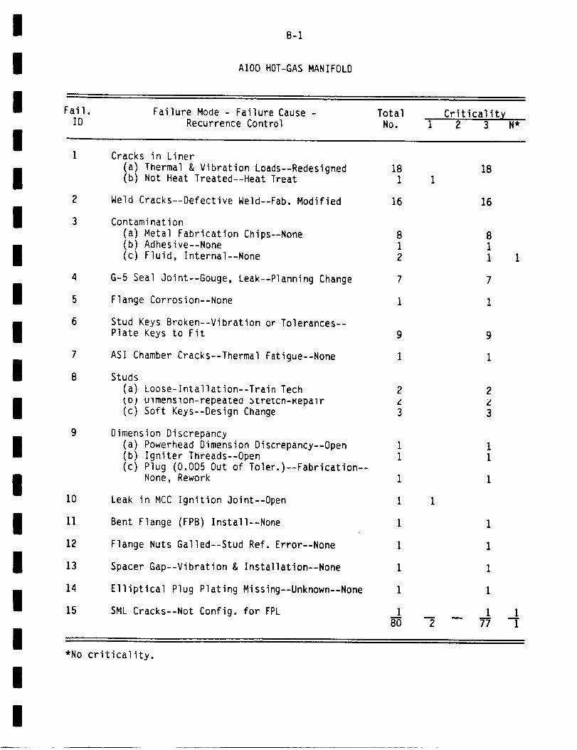
!
i
!Fail.
B-1
AIO0 HOT-GAS MANIFOLD
Failure Mode - Failure Cause - Total
!ID Recurrence Control NO.
Criticality1 2 3 N*
I
I
II
III
II
i
II
I
2
3
4
5
6
7
8
9
10
11
12
13
14
15
Cracks in Liner
(a) Thermal & Vibration Loads--Redesigned(b) Not Heat Treated--Heat Treat
Weld Cracks--Defective Weld--Fab. Modified
Contamination
(a) Metal Fabrication Chips--None(b) Adhesive--None
(c) Fluid, Internal--None
G-5 Seal Joint--Gouge, Leak--Planning Change
Flange Corrosion--None
Stud Keys Broken--Vibration or Tolerances--
Plate Keys to Fit
ASI Chamber Cracks--Thermal Fatigue--None
Studs
(a) Loose-lntallation--Train Tech
tD) ulmenslon-repeatea _zre_cn-Kepalr(c) Soft Keys--Design Change
Dimension Discrepancy
(a) Powerhead Dimension Discrepancy--Open
(b) Igniter Threads--Open(c) Plug (0.005 Out of Toler.)--Fabrication--
None, Rework
Leak in MCC Ignition Joint--Open
Bent Flange (FPB) Install--None
Flange Nuts Galled--Stud Ref. Error--None
Spacer Gap--Vibration & Installation--None
Elliptical Plug Plating Missing--Unknown--None
SML Cracks--Not Config. for FPL
18
1
16
8
12
7
1
9
1
2
L
3
11
1
1
1
1
1
1
1
80
1
2
18
16
1
1
1
1
1
77
81
I 1
7
1
I-i
i*No criticality.
!

Fail.ID
2
3
4
5
6
7
8
B-2
A150 HEAT EXCHANGER
Failure Mode - Failure Cause -Recurrence Control
TotalNo.
Coil Dings(a) Bracket Clearance--Redesign(b) Tech Mishandling--Mfg. Change
Coil Crack-Fitting Material Incorrect--National Change
Coil Leak--Wear--None
Coil Clearances--Mfg.--Mfg. Changes
Coil-Bent Tubes, Clearance Problems--Planning Change
Coil Leak--Weld Incomplete--Inspection
Bypass Line--Damaged When Removed--None
Forward Vane--Inclusion--Open
3
i
1
i18
i
4
Criticalityi 2 3
i12
22
III
l
I
II
II
iI
I
II
II
III

B-3
A200 MAIN INJECTOR
Fail. Failure Mode - Failure Cause - Total CriticalityID Recurrence Control No. 1 2 3 N
Heat Shield Retainers
I
II
I
III
II
I
II
I
2
3
16
15
26
25
9
5
18
2O
7
14
21
(a) Damage--New Heavy Design(b) Secondary Failure
(c) Gas Turbulence--FPL--Change
(d) Open
Baffles--Cracks, Erosion (Replace as Needed)
Lox Posts--Broken, Cracked
(a) Broken-Gas Turbulence FPL--ChangeStructure
(b) Thermal Overload--None
(C) Open
Lox Post--Erosion
(a) Blocked Orifice--Repair
(b) High Cycle Fatigue--Material Change
(c) Braze Joint--Leak--Spec Change
Lox Posts--Crooked, Bent--Inspect
Lox Posts--Plugged
Braze Joints--Leaks, Cracks--Inspect
Buffles--Loose Improper Installation--None
Heat Shield--Cracks, Thermal--New Retainers
Heat Shield--Cracks @ FPL--Unshaped Structure
Lox Post Inertia Weld-Spalling (FPL)--None
Primary Face Plate
(a) Erosion--High Cycle Fatigue--Mat'l Change
(b) Cracks--Load Distribution--Inspection
Interpropellant Plate
(a) Cracks--Heat Shield Failure--BetterRetainers
(b) Cracks--Gas Turbulence FPL--U-StructureInstalled
(c) Cracks--Open
Secondary Face Plates--Chaffed--Improper Assy.
84
193
20
3I1
3
1
3
2
1
3
1
3
31
2
8
419
3
20
21
3
31
1
1
1
3
2
1
3
1
13
3
31
2
2
!
!c-;)_

Fail.
B-4
A200 MAIN INJECTOR (CONTINUED)
Failure Mode - Failure Cause - Total Criticality
I
II
ID Recurrence Control No. 1 2 3 N
I24
6
22
23
17
19
10
11
Secondary Face Plate Retainers(a) Cracked--Insufficient @ FPL--Redesign(b) Cracked--Plugged Post(c) Not Flush--No Problem
Face Nuts (Erosion)(a) Local Over Heating--Maintenance(b) Secondary--Hot Gas Containment--Redesign(c) Mismachined Orifice--Plugged Post-Repair
344
Blocked Fuel Inlet--None
ASI Supply Line--Cracks, Liquid Embrittlement--Redesign 5
Reinforcement Ring Damage(a) Torn-lmproper Assy.--Planning Change(b) Damage--Secondary Failure--None(c) Damage-Gas Turb. @ FPL--U-Structure
Design
43
4
T-Bolts
Ca) Loose-lmproper Assy.--Design Change(b) Loose--Operation-Maintenance
4i
Strain Gauges--Inoperative--None 3
Contaminants--Metal From Other Failures--None 17
Broken Fuel Filters--Insufficient Life--Eliminate 25
175m
5
17
25
3
m
35
III
I
II
I
II
II
III
I
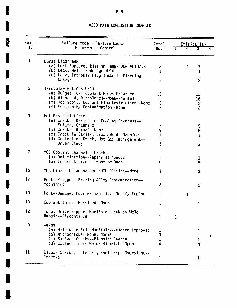
!
I
B-5
A300 MAIN COMBUSTION CHAMBER
Fail.
ID
1
Failure Mode - Failure Cause -
Recurrence ControlTotal
No.Criticality
I 2 3
Burst Diaphragm
I
I
i
I
I
II
III
I
I
I
2
3
7
15
17
18
i0
12
9
ii
(a) Leak-Rupture, Rise in Temp--UCR A010713
(b) Leak, Weld--Redesign Weld
(c) Leak, Improper Plug Install--PlanningChange
Irregular Hot Gas Wall
(a) Bulges--Ok--Coolant Holes Enlarged(b) Blanched, Discolored--None--Normal
(c) Hot Spots, Coolant Flow Restriction--None(d) Erosion by Contamination--None
Hot Gas Wall Liner
(a) Cracks--Restricted Cooling Channels--Enlarge Channels
(b) Cracks--Normal--None
(c) Crack in Cavity, Crown Weld--Machine
(d) Centerline Crack, Hot Gas Impingement--Under Study
MCC Coolant Channels--Cracks
(a) Delamination--Repair as Needed_bl Inherent CrackK--Nnnp nr hnmn
MCC Liner--Delamination EDCU Plating--None
Port--Plugged, Brazing Alloy Contamination--Machining
Port--Damage, Poor Reliability--Modify Engine
Coolant Inlet--Missized--Open
Turb. Drive Support Manifold--Leak by WeldRepair--Discontinue
Welds
(a) Hole Near Exit Manifold--Welding Improved(b) Microcracks--None, Normal(c) Surface Cracks--Planning Change(d) Coolant Inlet Welds Mismatch--Open
Elbow--Cracks, Internal, Radiograph Oversight--Improve
8
1
2
1516
2
2
5
8
1
3
1 71
15
16
22
5
8
1
1(}
3
2
I
!
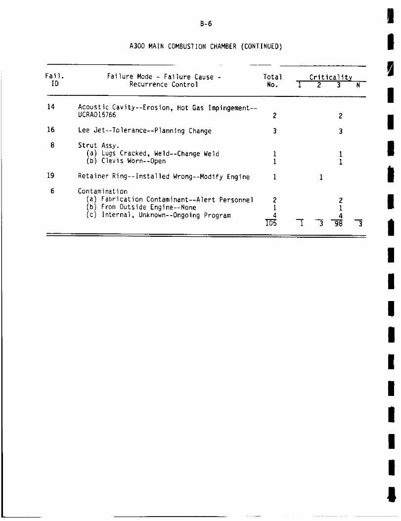
Fail.ID
B-6
A300 MAIN COMBUSTION CHAMBER (CONTINUED)
Failure Mode - Failure Cause -
Recurrence ControlTotalNo.
Criticality1 2 3 N
III
|I
14
16
8
19
6
Acoustic Cavity--Erosion, Hot Gas Impingement--UCRA015766
Lee Jet--Tolerance--Planning Change
Strut Assy.
(a) Lugs Cracked, Weld--Change Weld
(b) Clevis Worn--Open
Retainer Ring--Installed Wrong--Modify Engine
Contamination
(a) Fabrication Contaminant--Alert Personnel
(b) From Outside Engine--None
(c) Internal, Unknown--Ongoing Program
2
1
4105
D
1
2
3
2
1
4
3 98m
3
i
!
!
!
!
!
!
i
IIiI
Ii
g

I
i
B-7
A340 NOZZLE
I Fail. Failure Mode - Failure Cause - Total Criticalit X
iID
2
Recurrence Control No. i 2 3 N
Nozzle Tubes
II
I!
i
I
I
g
I
i
I
I
I
|
14
6
(a) Ruptures, Leaks--Local Overheat--Cutoff
Sequence Change 5(b) Leaks--From Previous Repairs--Repair 44
(c) Leaks--Braze Bond & Voids--RA 1607--014 Amended 18
(d) Cracks--Incorrect Braze Alloy--IL-78-CD-3139 3
(e) Cracks--Local Thermal Strains & FlowRestr.--Thicker Wall Tubes 41
(f) Cracks--Mishandling--Repair as Necessary 2(g) Ruptures--Inadequate Expm. Band Design--
Design Change 2(h) Leaks--Strains @ Braze Bonds--Fabrication
Change 36
(i) Leaks--Internal Corrosion--PlanningChange 6
(j) Leaks--Open 4
Brazing Voids on Tubes
(a) Brazing Voids--Inadequate--DoublersInstalled 7
# &_ _ ._--_-_--, --t ..., _ "v" L_.+ T ............... I.. ,tJl l--
None 4
(c) Separation of Tubes--From Previous
Repair--None 1
Nozzle Plating Failure--Inadequate--Steerhorn--
Redesign
Nozzle Fel.dline Wall Thickness Undersize--
Metal Ground--Redesign
Nozzle Tubes--Secondary Failure--Injector Post
Broke--Repair
Welds
(a) Support Bracket to Hotbend Broke--Vibration--Reinforcement i
(b) Aft Manifold Weld--Vibration & Thermal
Fatigue--None 5(c) Spot Welds--Broken From Drain Bracket--
Redesign 4
(d) Nozzle Bracket Weld Broke--Vibrations--Repair 1
(e) TPS Spot Welds Broke Welds--InadequateWelds--None i
544
15
3
412
2
33
64
7
4
1
2
I

B-8
A340 NOZZLE (CONTINUED)
!!
IFail.
IDFailure Mode - Failure Cause -
Recurrence ControlTotal
No.Criticalit X
i 2 3
i
II
15
i0
19
(f) Broken DFI Bracket Welds--Vibration--Add Clips
(g) TPS Bracket Welds Fail--Added Loads--Eliminate Brackets
(h) Steerhorn Fillet Welds--TransientLoads--None
(i) Spot Welds, Fuel Supply Duct--UnspecifiedRouting--Spec. Change
(j) Spot Welds DFI, Hyd Drain--Redesign(k) Spot Welds Broken--Random Failures--
Configuration Change(I) Support Bracket Debonded--New Repair
Procedure(m) Weld Broke--Vibration--Incomplete Weld--
Repair(n) Broken Weld/Open
Outer Jacket(a) Cracks--Thermal Cycling--Reworked(b) Cracks--Fabrication--Change Fabrication
Hyd. Drain Bracket Broken--External Fire--Improved Design
Hot Band
(a) Crack #9 HB--Previous Repair--Prepared
(b) HB #9 Tube--Material Deterioration--
Drawing Change(c) HB Pinholes--Stress Corrosion--None
(d) Hyd. Drain & Hot Bend Leak--Transients--
Redesign(e) Leak, Cold Weld-lnadequate Expm. HB--
Design Change(f) HB Aft Manifold Leak-Strain Crack @
Braze--Fabrication Change
Filler Weld Wire Incorrect--Mixed Lots by
Supplier--Caution
Joint Leaks
(a) Leak @ F6.7--Seal Replaced
(b) Leak @ F6.10--Inadequate Requirements--Improved
(c) Leaks @ F17--Seal Not Positioned--None
Tubes Blocked--Contamination--Repair
2
9
1
32
11
1
4
7
2
2
i
9
2
i
I
14
1
2
9
1
3
2
11
1
4
7
3
i
2
!IIIi
II
|IiIII|I
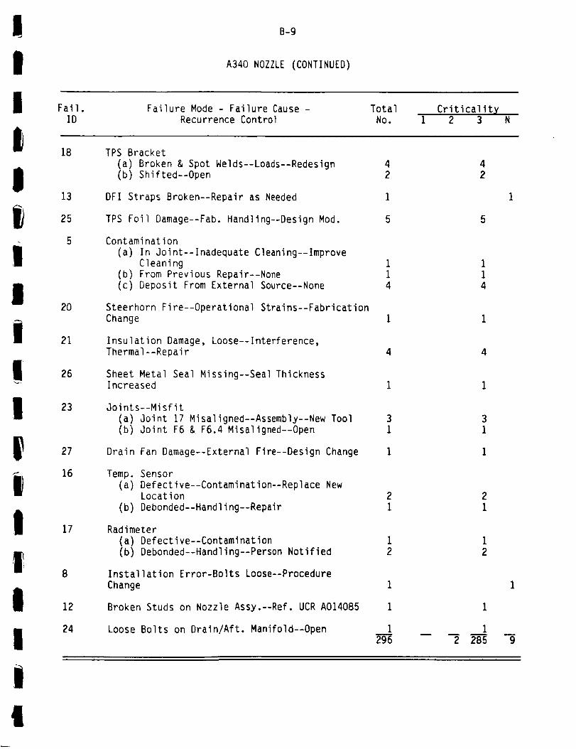
III Fail.
B-9
A340 NOZZLE (CONTINUED)
Failure Mode - Failure Cause - Total Criticalit X
IID
18
Recurrence Control No. I 2 3 N
TPS Bracket
I
II
l!I
|1I
II
13
25
5
20
21
26
23
27
16
17
8
12
24
(a) Broken & Spot Welds--Loads--Redesign
(b) Shifted--Open
DFI Straps Broken--Repair as Needed
TPS Foil Damage--Fab. Handling--Design Mod.
Contamination
(a) In Joint--Inadequate Cleaning--Improve
Cleaning(b) From Previous Repair--None
(c) Deposit From External Source--None
Steerhorn Fire--Operational Strains--Fabrication
Change
Insulation Damage, Loose--Interference,Thermal--Repair
Sheet Metal Seal Missing--Seal ThicknessIncreased
Joints--Misfit(a) Joint 17 Misaligned--Assembly--New Tool(b) Joint F6 & F6.4 Misaligned--Open
Drain Fan Damage--External Fire--Design Change
Temp. Sensor(a) Defective--Contamination--Replace New
Location(b) Debonded--Handling--Repair
Radimeter
(a) Defective--Contamination
(b) Debonded--Handling--Person Notified
Installation Error-Bolts Loose--Procedure
Change
Broken Studs on Nozzle Assy.--Ref. UCR A014085
Loose Bolts on Drain/Aft. Manifold--Open
4
2
i
5
21
12
1
1
1
296
11
4
4
2 285m
9
!
!

Fail.
B-IO
A600 FUEL PREBURNER
Failure Mode - Failure Cause - Total
!!!
ID Recurrence Control
Baffles (Erosion)
NO.Criticality
1 2 3
i
2
6
(a) Erosion-Water & Ice--New DryingProcedures
(b) Erosion--High Local Mixture Ratio--
Repair
(c) Erosion--ASI Hot Gas Impingement--None(d) Erosion--Feed Coolant Channel Blocked--
Open Coolant Holes(e) Erosion--Secondary Failure--Turb. Duct--
Ref. UCR A018306
Baffles Cracked--High Mixture Ratio--ReplaceAs Needed
Lox Posts Nonconcentric, Blocked
(a) Nonconcentric--Improper Installation--Correct As Needed
(b) Slag Blockage--Reworked(c) Nonconcentric--Thermal Distortion--R&D
(d) Blocked--Installation--Reworked
Lox Posts Erosion
(a) Erosion--Water & Ice--New DryingProcedure
(b) Nibbling--Temp. Spikes, High MixtureRatio--Repair
(c) Erosion--Contamination--Repair as Needed
(d) Crack in Oxidizer Post--Alternate Design
Face Plate Erosion
(a) Erosion--Flow Inpingement--DivergentLiner Installed
(b) Erosion--Water & Ice--New DryingProcedure
(c) Box Pin Missing--Erosion--Repair
(d) Erosion--Slag In Fuel Anulus--ImproveDesign
(e) Bowing Plate--Welding--Repair(f) Erosion--Fabrication Debris--None
(g) Erosion--Blocked Coolant Orifice
(h) Erosion--Unknown or Open
(i) Erosion--Secondary Failure--Ref. UCR A018288
1
14
I
1
6
3
6
11
I
7
7
Face Plate Cracks--Low Cycle Fatigue--HotGas--Divergent Liner Added 2
2
1
37
2
1
4
2
1
1
1
i
1411
!
!
IigI
II!I!
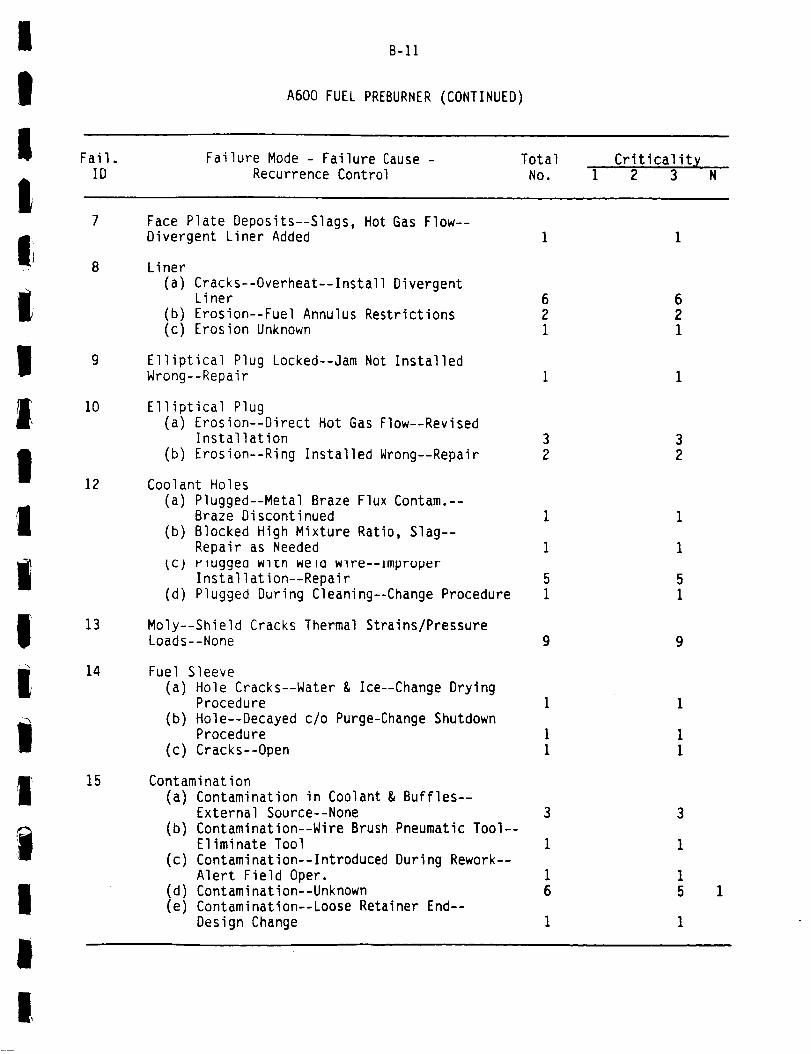
I
II Fail.
B-11
A600 FUEL PREBURNER (CONTINUED)
Failure Mode - Failure Cause - Total Criticality
IID Recurrence Control No. I 2 3 N
m
I!Il
m
IiiI
Ii
i0
12
13
14
15
Face Plate Deposits--Slags, Hot Gas Flow--
Divergent Liner Added
Liner
(a) Cracks--Overheat--Install DivergentLiner
(b) Erosion--Fuel Annulus Restrictions(c) Erosion Unknown
Elliptical Plug Locked--jam Not InstalledWrong--Repair
Elliptical Plug
(a) Erosion--Direct Hot Gas Flow--RevisedInstallation
(b) Erosion--Ring Installed Wrong--Repair
32
Coolant Holes(a) Plugged--Metal Braze Flux Contam.--
Braze Discontinued(b) Blocked High Mixture Ratio, Slag--
Repair as Neededtc) rluggea wl_n were wlre--improper
Installation--Repair(d) Plugged During Cleaning--Change Procedure
Moly--Shield Cracks Thermal Strains/PressureLoads--None 9
Fuel Sleeve
(a) Hole Cracks--Water & Ice--Change DryingProcedure
(b) Hole--Decayed c/o Purge-Change ShutdownProcedure
(c) Cracks--Open
Contamination(a) Contamination in Coolant & Buffles--
External Source--None(b) Contamination--Wire Brush Pneumatic Tool--
Eliminate Tool
(c) Contamination--Introduced During Rework--Alert Field Oper.
(d) Contamination--Unknown(e) Contamination--Loose Retainer End--
Design Change
621
32
I
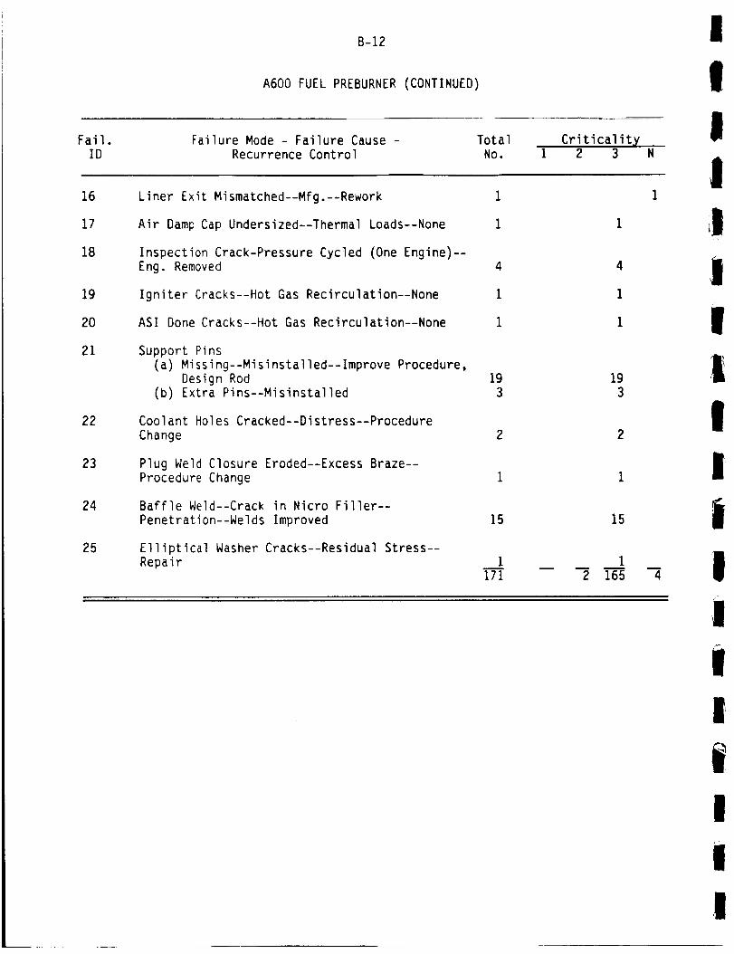
Fail.
B-12
A600 FUEL PREBURNER (CONTINUED)
Failure Mode - Failure Cause - Total Criticalit X
I
!
!ID Recurrence Control No. 1 2 3 N
I16
17
18
19
2O
21
22
23
24
25
Liner Exit Mismatched--Mfg.--Rework
Air Damp Cap Undersized--Thermal Loads--None
Inspection Crack-Pressure Cycled (One Engine)--Eng. Removed
Igniter Cracks--Hot Gas Recirculation--None
ASI Done Cracks--Hot Gas Recirculation--None
Support Pins
(a) Missing--Misinstalled--Improve Procedure,
Design Rod(b) Extra Pins--Misinstalled
Coolant Holes Cracked--Distress--Procedure
Change
Plug Weld Closure Eroded--Excess Braze--
Procedure Change
Baffle Weld--Crack in Nicro Filler--
Penetration--Welds Improved
Elliptical Washer Cracks--Residual Stress--
Repair
4
1
1
19
3
15
1
171
193
2
15
m
2 165 4
i!II|
|I
/ •
I
!I
I
i!

I
i! Fail.
B-13
A700 OXIDIZER PREBURNER
Failure Mode - Failure Cause - Total Criticality
IID Recurrence Control No. 1 2 3 N
|I
1III
!
Ii
8
Lox Posts
(a) Slight Melting--Normal After PFC Tests--None
(b) Erosion--Contamination in Fuel Annulus--None
Lox Orifices Cracks--Hot Gas Recirculation--None
Lox Post, High Eddy Reading--Work Hardened--
Spec Change
Liner Erosion--Contamination in Fuel Annulus--None
Dome--Void--None
Welds
(a) Weld--Buildup--Revised Drawing
(b) Weld #3 Hairline Crack--Open
Lox Post Support Pin Dislodged Installation
Contamination From Fuel Filter External toEngine--Eliminate Filter
Contamination From Heat Shield Failure--Redesign 1
13
1
2
2
113
II
It|I
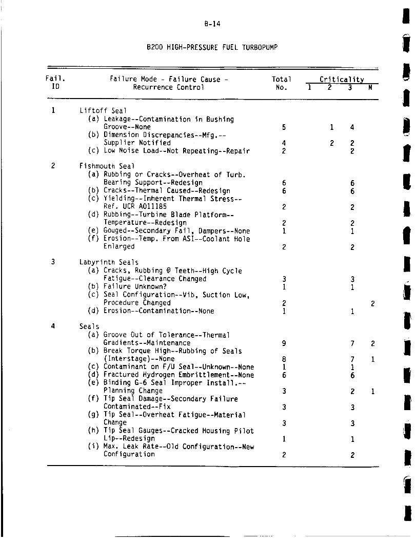
Fail.
B-14
B200 HIGH-PRESSURE FUEL TURBOPUMP
Failure Mode - Failure Cause - Total Criticality
I
!ID Recurrence Control No. I 2 3 N
Liftoff Seal
(a) Leakage--Contamination in BushingGroove--None
(b) Dimension Discrepancies--Mfg.--Supplier Notified
(c) Low Noise Load--Not Repeating--Repair
Fishmouth Seal
(a) Rubbing or Cracks--Overheat of Turb.
Bearing Support--Redesign(b) Cracks--Thermal Caused--Redesign(c) Yielding--Inherent Thermal Stress--
Ref. UCR A011185
(d) Rubbing--Turbine Blade Platform--
Temperature--Redesign
(e) Gouged--Secondary Fail, Dampers--None(f) Erosion--Temp. From ASI--Coolant Hole
Enlarged
Labyrinth Seals
(a) Cracks, Rubbing @ Teeth--High CycleFatigue--Clearance Changed
(b) Failure Unknown?
(c) Seal Configuration--Vib, Suction Low,
Procedure Changed(d) Erosion--Contamination--None
Seals
(a) Groove Out of Tolerance--ThermalGradients--Maintenance
(b) Break Torque High--Rubbing of Seals(Interstage)--None
(c) Contaminant on F/U Seal--Unknown--None
(d) Fractured Hydrogen Embrittlement--None(e) Binding G-6 Seal Improper Install.--
Planning Change
(f) Tip Seal Damage--Secondary FailureContaminated--Fix
(g) Tip Seal--Overheat Fatigue--MaterialChange
(h) Tip Seal Gauges--Cracked Housing PilotLip--Redesign
(i) Max. Leak Rate--Old Configuration--NewConfiguration
5
4
2
66
2
2
1
2
9
8
16
3
3
3
1
2
1 4
2 2
2
2
2
1
|
!!
I
II
!
!i!
i
!
I
|
I

i
!I
Fail.
B-15
B200 HIGH-PRESSURE FUEL TURBOPUMP iCONTINUED)
Failure Mode - Failure Cause - Total
IID Recurrence Control NO.
Criticalityi 2 3 N
!I
!
i
|
l
!I
I,|
I
!
(j) Seal Separating--Secondary Failure 2(k) Kel-F Seal Damage--Retainer Motion--
Redesign 2
(1) Seal Crack/Leak--Low Cycle Fatigue--None 1
(m) G5 Seal Grooves Stained--Residual Com-
bustion Products--None 2
in) Pitting on G-5 Seal--Secondary--Ref.UCR A014015 1
(o) Kel-F Seal Failure--Secondary--SpecialInspection 1
(p) Broken Seals--Undetermined 3(q) Delaminated Seal--Inadequate Cleaning--
Material Change iJr) Leak Joint F-4--Oversize Groove--
Planning Change i
Turbine Blades--Erosion
(a) Erosion, Burnt--Secondary Failure--Ref. UCR A016031
(b) Erosion, 1st Stage--Transient ThermalEnvironment--RedesiQn
(c) Erosion--Rubbing, Overspeed--None(Normal)
(d) Erosion--Thermal Environment--Redesign
Blades--Cracked, Damage(a) Deformed/Drawings--Contamination--Seal
Redesign
(b) Cracked Blade--Combined HCF/LCF--Inspection
(c) Blade Failures, Premature Cutoff--FPB
Configuration--None, Unique Conf.
(d) Cracked Shunks--Low Cycle Fatigue--None
ie) Fracture--Moisture--New Drying Procedureif) 2nd Stage Damage--Dislodged Damper--
Ref. A013999
Turbine Platform Erosion--ASI Temp.--Redesign& Coolant Holes Enlarged 12
1
1
2
5
1
21
11
II
I

B-16
B200 HIGH-PRESSURE FUEL TURBOPUMP (CONTINUED)
I
II
Fail.ID
Failure Mode - Failure Cause -Recurrence Control
TotalNo.
Criticality1 2 3
i8
10
12
13
14
Sheet Metal
(a) Cracking--Fitup Weld Variation--Inspect 8
(b) Crack in Turbo Shroud--High Cycle
Fatigue--Material Change I(c) Crack--Secondary Failure 1
(d) Cracking--Full Power Level (FPL)--Monitor 2
(e) Crack-Weld Bead Notch--Design Change 2(f) Cracks--Built in Insufficiency--Redesign 35
Inlet/Discharge
(a) Linear Cracks--Overstressed--Spec Change 1
(b) Cracks--High Cycle Fatigue--Monitor 2
(c) Cracks--Insufficient Joint Strength--Spec. Change 2
(d) Damage--Open 1
1Synchronous Vibration--Unknown--Limit Unbalance
Vanes
(a) Turbine Edge Damage--Debris, SecondaryFailure--Ref. A012653
(b) Erosion, FPB Malfunction--UCR A004402(c) Erosion, ist Stage--High/Low Cycle
Fatigue--Material Change(d) Burn Through--Secondary Failure--
Ref. UCR A016031(e) Nick--Weld Operation--Rework(f) Erosion, Hot Preburner Start-Limit
Established(g) Hole--Open(h) Erosion--Rapped Gas Pocket--Life Limit
Established(i) Material Missing--Open
Rub Ring Warped--Misinstalled--Notified Person
Contamination(a) Self-Generated--No Problem(b) Installation--None(c) Unknown, Minor, Gold--None(d) Bearing Debris--None(e) Spring Debris--Vibration--None(f) Blade Rubbing Redesign(g) Heat Shield Damage--Secondary, UCRAOI5968(h) Unknown--Suspect Seal Wear(i) Ref. UCR A004585
5
12
26I
21
5
5I
ii22
35
1
2
21
1
I
3
6
22
512
251
21
5
I
II
I!II
iI
t
I
I
II
I

Fail.
B-17
B200 HIGH-PRESSURE FUEL TURBOPUMP (CONTINUED)
Failure Mode - Failure Cause - Total CriticalityID
16
Recurrence Control No. i 2 3 N
Struts/Posts
17
18
19
20
21
22
23
24
25
(a) Cracks--Sheet Metal Fitup & WeldVariations--Inspect
(b) Cracks--High Cycle Fatigue, FPL--Posts Modified
(c) Cracked--Oversized Electrode Repair
(d) Cracks--Weld Bend Notch--Design Change
Nickel Insulation Damage--Repair as Needed
Bolt Holes Cracks--Internally Induced--
Redesign Turbine
Impeller Broken--Internal Rubbing--Material
Change
Bellows Shield
(a) Cracks--Thermal Spikes--Inspect
(b) Crack--High Cycle Fatigue--ECR 09689
(c) Crack--Machining--None
(d) Weld Crack--Tolerances--Change Planning(e) Cracks--Open
T/A Manifold
(a) Cracks--Thermal Gradients--Repair
(b) Damage--Weld Failure--Planning Change
Bearing Balls(a) Thrust Ball Cracks--Dry Lube Overheat--
Maintenance
(b) Loose--Improper Swage--Planning Change
(c) Streaks Eccentric Wear--Tooling--Correct
(d) Wear--Cantom. Unknown?
Shaft Insert Wear with Balls--Ref. UCR A003411
Bearing Race(a) Wear--Contamination--None
(b) Scoring--Outer Race Preload--Ref. A011480
(c) Cracked--Misalignment Planning Change
Turbine End Ring
(a) Cracks--Sheet Metal & Weld Variations--Maintenance
(b) Plating & Peeling--Ambiguous ReworkSpecs--Change Specs.
47
1533
9
8
47
1433
9
8
31
41
2
1
2
1
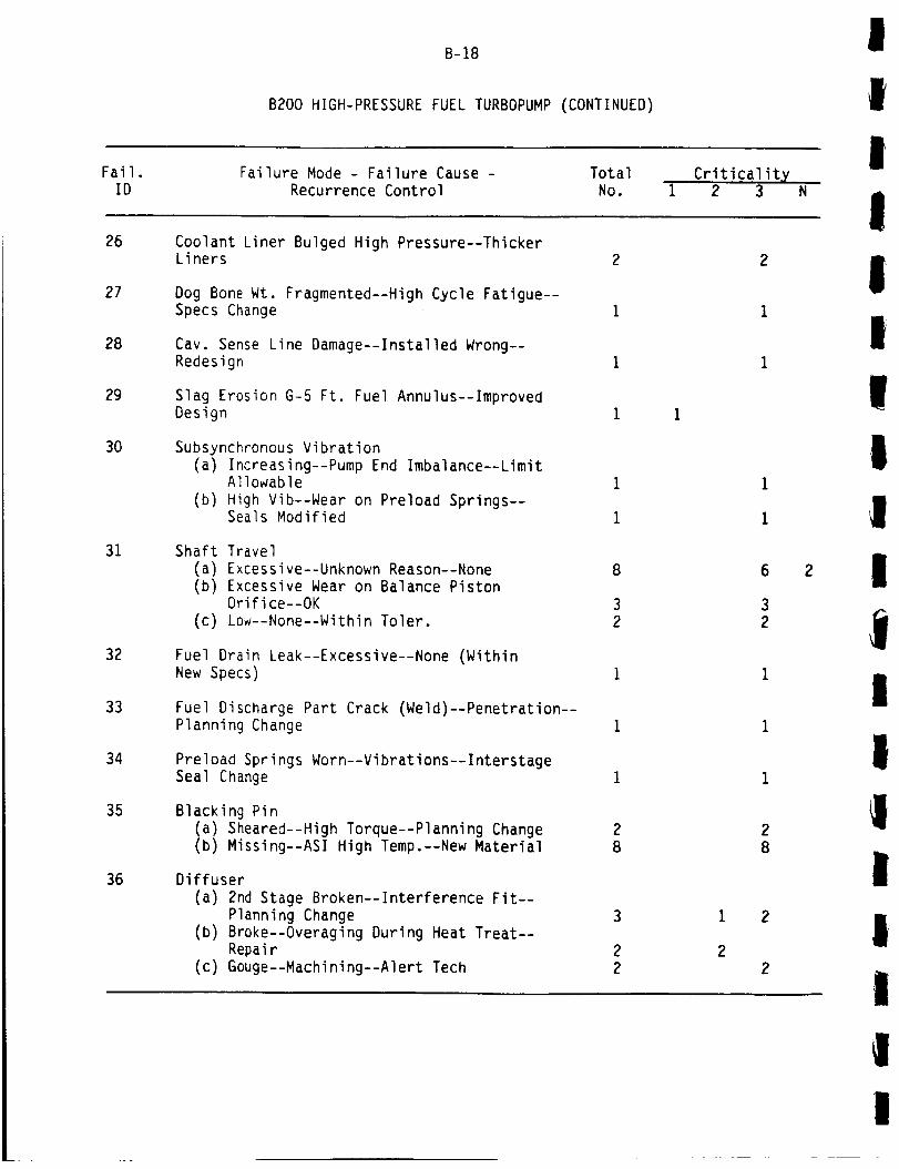
B-18
B200 HIGH-PRESSUREFUELTURBOPUMP(CONTINUED)
IiI
Fail.
IDFailure Mode - Failure Cause -
Recurrence Control
Total
No.Criticality
1 2 3 N
!26
27
28
29
30
31
32
33
34
35
36
Coolant Liner Bulged High Pressure--ThickerLiners
Dog Bone Wt. Fragmented--High Cycle Fatigue--Specs Change
Cav. Sense Line Damage--Installed Wrong--Redesign
Slag Erosion G-5 Ft. Fuel Annulus--Improved
Design
Subsynchronous Vibration(a) Increasing--Pump End Imbalance--Limit
Allowable(b) High Vib--Wear on Preload Springs--
Seals Modified
Shaft Travel(a) Excessive--Unknown Reason--None(b) Excessive Wear on Balance Piston
Orifice--OK(c) Low--None--Within Toler,
Fuel Drain Leak--Excessive--None (WithinNew Specs)
Fuel Discharge Part Crack (Weld)--Penetration--
Planning Change
Preload Springs Worn--Vibrations--InterstageSeal Change
Blacking Pin
(a) Sheared--High Torque--Planning Change(b) Missing--ASI High Temp.--New Material
Diffuser
(a) 2nd Stage Broken--Interference Fit--
Planning Change(b) Broke--Overaging During Heat Treat--
Repair
(c) Gouge--Machining--Alert Tech
8
32
2
8
3
22
2
2
,
I
III
i
JI
t
iII
|I

!
I
B-19
B200 HIGH-PRESSURE FUEL TURBOPUMP (CONTINUED)
I
|Fail.
ID
37
Failure Mode - Failure Cause -Recurrence Control
Total
No.Criticality
1 2 3
Nozzle Cracks
II
!
!
IiII
III
II
38
39
40
41
42
44
45
46
47
48
(a) Crack--Thermal Low Cycle Fatigue--Change FPB
(b) Erosion--High Transients--Redesign
High Accelerometer Signals
(a) Vibration (16g) Cavitation Wrong Labyrinth
Seal Conf.--Procedure Change(b) High Levels--Unknown--None
Inlet Cap Nut
(a) Crack/Erosion-ASI Temperature--Redesign
Saureisen Material Washed Out--ASI Temp.--Cool Hole Mode
Nuts & Washers
(a) Missing From Shield--Unknown--InterimDesign
(b) Loose Nut--Typical--None(c) Discharge Bolt Loose--Open(d) Lugs Missing--Open
HPFT (Water Contamination)
(a) Water Trapped in Pump--None
(b) Water in Bellows--New Drying Procedure(c) Moisture in Bearing Support--None
Inlet Failure--Pump Cavitation--RequirementsChange
Bearing Support(a) Crack--Open
(b) Crack--Insufficient Joint Strength--Limits Estab.
Missing Damper--Damaged Blades--Open
Dimension Discrepancies--Afterburn--New Specs
Seal Tabs
(a) Cracked--Load--Redesign
(b) Missing--Hot Gas Impingement--Redesign
13
1
1
457
2
2
3 Ii
13
429I
14
I
I
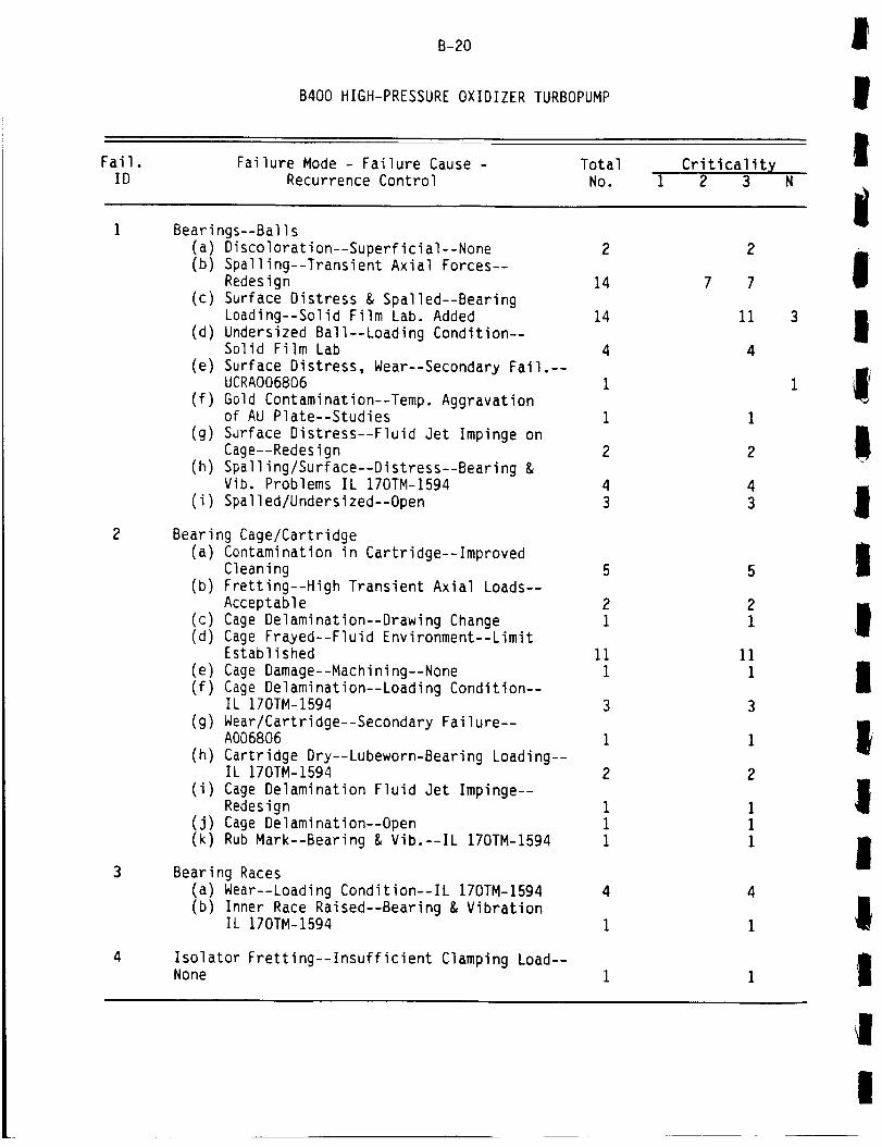
B-20
B400 HIGH-PRESSURE OXIDIZER TURBOPUMP
Fail. Failure Mode - Failure Cause - Total Criticality
I
I!
ID Recurrence Control No. 1 2 3 N
|
2
Beari
(a)(b)
(c)
(d)
(e)
(f)
(g)
(h)
(i)
ngs--Balls
Discoloration--Superficial--None 2
Spalling--Transient Axial Forces--Redesign 14
Surface Distress & Spalled--BearingLoading--Solid Film Lab. Added 14
Undersized Ball--Loading Condition--Solid Film Lab 4
Surface Distress, Wear--Secondary Fail.--UCRAO06806 1
Gold Contamination--Temp. Aggravationof AU Plate--Studies 1
Surface Distress--Fluid Jet Impinge onCage--Redesign 2
Spalling/Surface--Distress--Bearing &Vib. Problems IL 170TM-1594 4
Spalled/Undersized--Open 3
Beari
(a)
(b)
(c)(d)
(e)(f)
(g)
(h)
(i)
(J)(k)
7
Beari
(a)(b)
2
7
11
4
ng Cage/Cartridge
Contamination in Cartridge--ImprovedCleaning 5 5
Fretting--High Transient Axial Loads--
Acceptable 2 2
Cage Delamination--Drawing Change I 1Cage Frayed--Fluid Environment--LimitEstablished 11 11
Cage Damage--Machining--None I 1
Cage Delamination--Loading Condition--IL 170TM-1594 3 3Wear/Cartridge--Secondary Failure--A006806 i ICartridge Dry--Lubeworn-Bearing Loading--IL 170TM-1594 2 2Cage Delamination Fluid Jet Impinge--Redesign i iCage Delamination--Open i IRub Mark--Bearing & Vib.--IL 170TM-1594 i i
ng Races
Wear--Loading Condition--IL 170TM-1594 4
Inner Race Raised--Bearing & VibrationIL 170TM-1594 1
Isolator Fretting--Insufficient Clamping Load--None
4
1
I
!
!
IlII
!Ii
!i!I
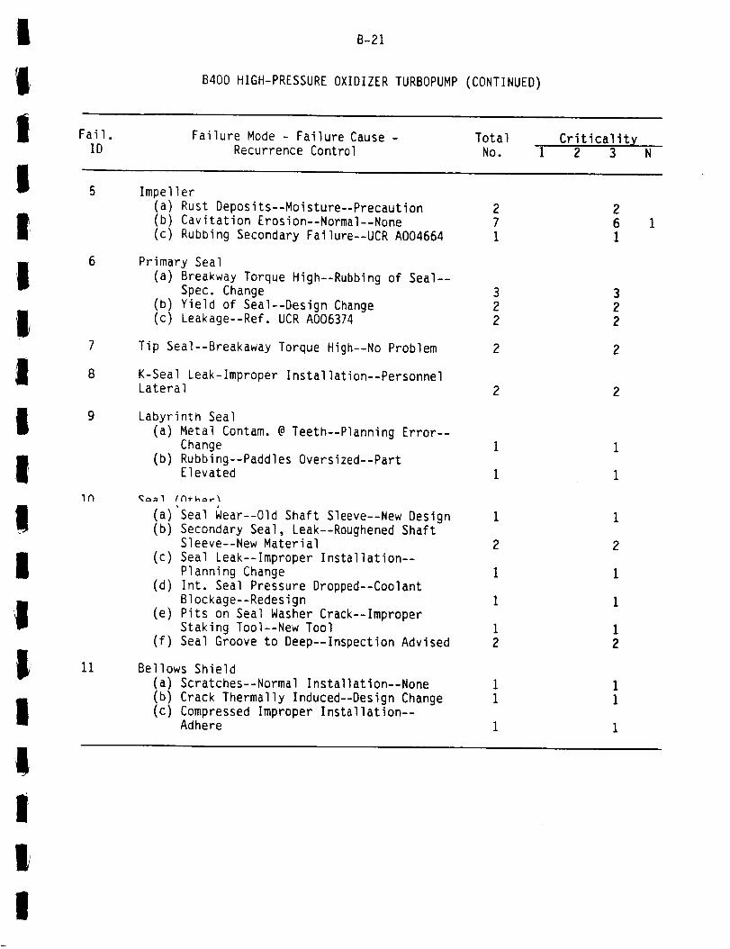
I
II,
! Fail.
B-21
B400 HIGH-PRESSURE OXIDIZER TURBOPUMP (CONTINUED)
Failure Mode - Failure Cause -
IID Recurrence Control
Total CriticalityNo. 1 2 3
Impeller
I
IIl
I
Ii
I
III
i
6
7
8
9
IN
11
(a) Rust Deposits--Moisture--Precaution(b) Cavitation Erosion--Normal--None
(c) Rubbing Secondary Failure--UCR A004664
27
1
Primary Seal
(a) Breakway Torque High--Rubbing of Seal--
Spec. Change
(b) Yield of Seal--Design Change(c) Leakage--Ref. UCR A006374
322
Tip Seal--Breakaway Torque High--No Problem 2
K-Seal Leak-lmproper Installation--PersonnelLateral 2
Labyrinth Seal
(a) Metal Contam. @ Teeth--Planning Error--Change
(b) Rubbing--Paddles Oversized--PartElevated
(a)'Seal Wear--Old Shaft Sleeve--New Design
(b) Secondary Seal, Leak--Roughened ShaftSleeve--New Material
(c) Seal Leak--Improper Installation--
Planning Change
(d) Int. Seal Pressure Dropped--Coolant
Blockage--Redesign
(e) Pits on Seal Washer Crack--ImproperStaking Tool--New Tool
(f) Seal Groove to Deep--Inspection Advised
1
2
1
1
1
2
Bellows Shield(a) Scratches--Normal Installation--None(b) Crack Thermally Induced--Design Change(c) Compressed Improper Installation--
Adhere
I
2
1
1
12
iII
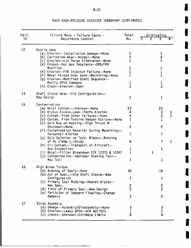
B-22
B400 HIGH-PRESSURE OXIDIZER TURBOPUMP (CONTINUED)
Fail. Failure Mode - Failure Cause - Total
Ii
ID
12 Nozzle Vane
Recurrence Control NO.Criticality
1 2 3 N
I
13
14
15
17
(a) Erosion--Installation Damage--None 1 1(b) Cavitation Wear--Normal--None 2 2(c) Erosion--c/o Purge Eliminated--None i I(d) Eroded--Hot Gas Imbalance--OPB/FPB
Modified i I(e) Erosion--FPB Injector Failure--None i I(f) Metal Folded Over Vane--Machining--None I i(g) Erosion--Modified Start Sequence--
Modify OPOV Command I i(h) Crack--Erosion--Open 3 3
Shaft Sleeve Wear--Old Configuration--New Design 1
Contamination(a) Metal Contam.--Unknown--None 23(b) Krytox Excess-Leak--Techs Alerted 4(c) Contam. From Other Failures--None 4(d) Contam. From Turbine Damper Failure--None i(e) Gold Rub on Housing--High Thrust @
Shutdown--None 2(f) Contamination Material During Machining--
Personnel Alerted 7
(g) Gold Splatter on Turb. Blades--Bondingof AU (Temp.)--Study 8
(h) Oil Contam.--Transport of Aircraft--Add Inspection i
(i) Metal--Filter Breakdown ECR 10370 & 10347 i(j) Contamination--Improper Staking Tool--
New Tool I
Hi
23331
2
gh Break Torque(a) Rubbing of Seals--None 18 18(b) Out of Spec.--Old Shaft Sleeve--New
Configuration i I(c) Primary Seal Rubbing--Heated Krytox--
New Spec. 2 2(d) Yield of Primary Seal--New Design 2 2(e) Particles of Dampers Floating--Change
Dampers 2 2
Strut Assembly(a) Damage--Assenbly/Disassembly--None 3(b) Erosion--Leaky OPOV--UCR A017523 I(c) Cracks--Unknown--Estimate Limits 6
I
III
I
iII
II'
I
!iII
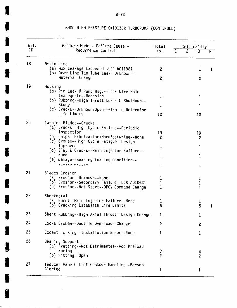
Fail.
B-23
B400 HIGH-PRESSURE OXIDIZER TURBOPUMP (CONTINUED)
Failure Mode - Failure Cause - Total Criticalit XID Recurrence Control No. 1 2 3 N
18
19
2O
21
22
23
24
25
26
27
Drain Line(a) Mux Leakage Exceeded--UCR A011981(b) Draw Line Tan Tube Leak--Unknown--
Material Change
Housing(a) Pin Leak @ Pump Hsg.--Lock Wire Hole
Inadequate--Redesign(b) Rubbing--High Thrust Loads @ Shutdown--
Study
(c) Cracks--Unknown/Open--Plan to DetermineLife Limits
Turbine Blades--Cracks
(a) Cracks--High Cycle Fatigue--PeriodicInspection
(b) Chips--Fabrication/Manufacturing--None(c) Broken--High Cycle Fatigue--Design
Improved(d) Slay & Cracks--Main Injector Failure--
None(e) Damage--Bearing Loading Condition--
IL-£/U I PI-13_H
Blades Erosion
(a) Erosion--Unknown--None(b) Erosion--Secondary Failure--UCR A010631
(c) Erosion--Hot Start--OPOV Command Change
Sheetmetal(a) Burnt--Main Injector Failure--None(b) Cracking Establish Life Limits
Shaft Rubbing--High Axial Thrust--Design Change
Locks Broken--Ductile Overload--Change
Eccentric Ring--Installation Error--None
Bearing Support(a) Fretting--Not Detrimental--Add Preload
Spring(b) Pitting--Open
Inducer Vane Out of Contour Handling--PersonAlerted
1
i
I0
19
2
1
1
1
i
i
I0
19
2
1
1
I
i
5
1
2
i
3
2
i
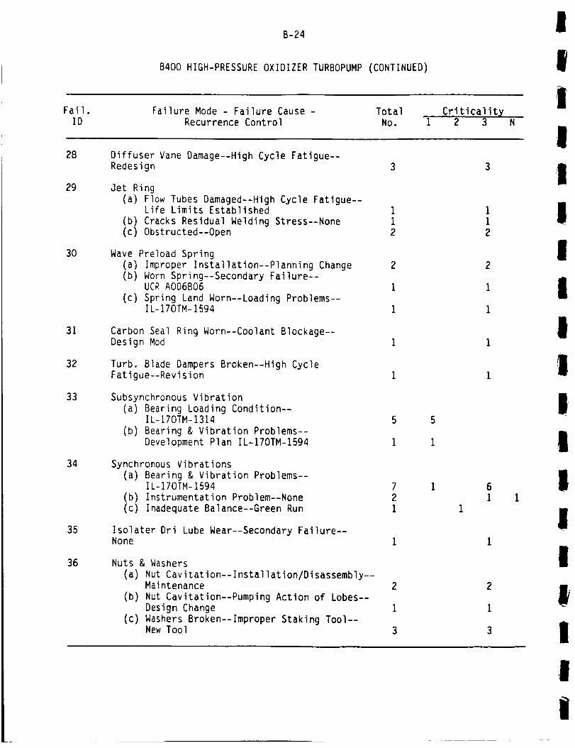
B-24
B400 HIGH-PRESSURE OXIDIZER TURBOPUMP (CONTINUED)
J
i
iFail.ID
Failure Mode - Failure Cause -
Recurrence ControlTotal
No.Criticality
1 2 3
!28
29
30
31
32
33
34
35
36
Diffuser Vane Damage--High Cycle Fatigue--Redesign
Jet Ring
(a) Flow Tubes Damaged--High Cycle Fatigue--Life Limits Established
(b) Cracks Residual Welding Stress--None(c) Obstructed--Open
Wave Preload Spring
(a) Improper Installation--Planning Change(b) Worn Spring--Secondary Failure°-
UCR A006806
(c) Spring Land Worn--Loading Problems--IL-170TM-1594
Carbon Seal Ring Worn--Coolant Blockage--Design Mod
Turb. Blade Dampers Broken--High CycleFatigue--Revision
Subsynchronous Vibration(a) Bearing Loading Condition--
IL-170TM-1314
(b) Bearing & Vibration Problems--Development Plan IL-170TM-1594
Synchronous Vibrations
(a) Bearing & Vibration Problems--IL-170TM-1594
(b) Instrumentation Problem--None(c) Inadequate Balance--Green Run
Isolater Dri Lube Wear--Secondary Failure--None
Nuts & Washers(a) Nut Cavitation--Installation/Disassembly--
Maintenance
(b) Nut Cavitation--Pumping Action of Lobes--
Design Change
(c) Washers Broken--Improper Staking Tool--New Tool
7
2
1
2
1
3
I
!I
I
II
l
I
tII
i
I|
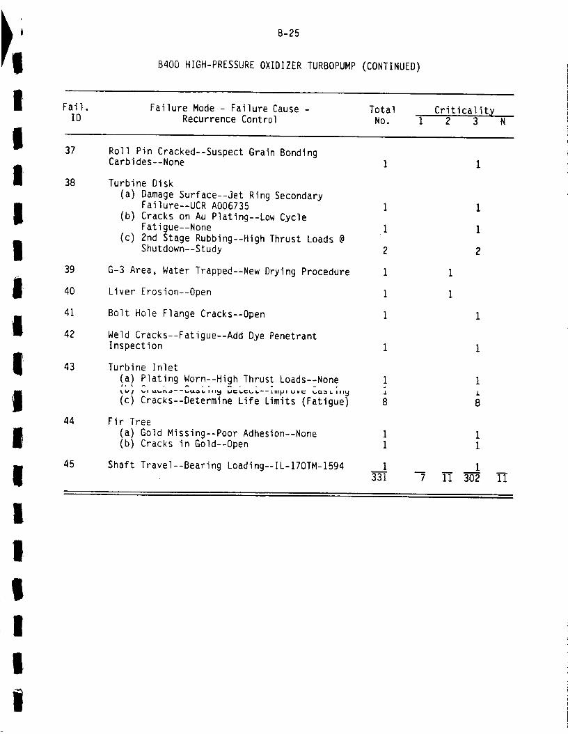
,L Fail.
B-25
B400 HIGH-PRESSURE OXIDIZER TURBOPUMP (CONTINUED)
Failure Mode - Failure Cause - Total Criticality
!ID
37 Roll
Recurrence Control No. 1 2 3 N
Pin Cracked--Suspect Grain Bonding
,
II
I
i!I
i
38
39
4O
41
42
43
44
45
Carbides--None
Turbine Disk
(a) Damage Surface--Jet Ring SecondaryFailure--UCR A006735
(b) Cracks on Au Plating--Low CycleFatigue--None
(c) 2nd Stage Rubbing--High Thrust Loads @Shutdown--Study
G-3 Area, Water Trapped--New Drying Procedure
Liver Erosion--Open
Bolt Hole Flange Cracks--Open
Weld Cracks--Fatigue--Add Dye Penetrant
Inspection
Turbine Inlet
(a) Plating Worn--High Thrust Loads--None
_ _1 _a----_ lil_ _C_C_----_III_I UVC _Q_ I1_
(c) Cracks--Determine Life Limits (Fatigue)
Fir Tree
(a) Gold Missing--Poor Adhesion--None(b) Cracks in Gold--Open
Shaft Travel--Bearing Loading--IL-170TM-1594
1
8
i
331n
7
1
1
2
ii 302m
11
I
III
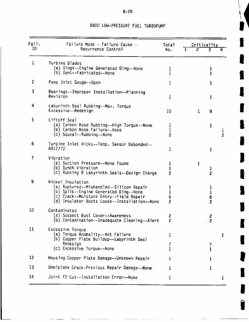
Fail.
B-26
B600 LOW-PRESSURE FUEL TURBOPUMP
Failure Mode - Failure Cause - Total Criticalit X IID Recurrence Control No. I 2 3 N
Turbine BladesI
4
6
10
11
12
13
!4
(a) Dings--Engine Generated Ding--None(b) Dent--Fabricated--None
Pump Inlet Gauge--Open
Bearings--Improper Installation--PlanningRevision
Labyrinth Seal Rubbing--Max. Torque
Excessive--Redesign 10
Liftoff Seal
(a) Carbon Nose Rubbing--High Torque--None(b) Carbon Nose Failure--None
(c) Squeal--Rubbing--None
Turbine Inlet Nicks--Temp. Sensor Debonded--A017772
Vibration(a) Suction Pressure--None Found(b) Synch Vibration(c) Rubbing @ Labyrinth Seals--Design Change
Nickel Insulation(a) Ruptured--Mishandled--Silicon Repair(b) Split--Engine Generated Ding--None(c) Crack--Moisture Entry--Field Repair(d) Insulator Boots Loose--Installation--None
Contaminated
(a) Suspect Dust Cover--Awareness
(b) Contamination--Inadequate Clearing--Alert
2
2
Excessive Torque
(a) Torque Anomality--Not Failure(b) Copper Plate Buildup--Labyrinth Seal
Redesign(c) Excessive Torque--None
Housing Copper Plate Damage--Unknown Repair
Omniplate Crack-Previous Repair Damage--None
I
II
Ii
Ii
II
I
Im
t
|

I
II
Fail.
B-27
B600 LOW-PRESSURE FUEL TURBOPUMP (CONTINUED)
Failure Mode - Failure Cause - Total Criticality
IID Recurrence Control No. 1 2 3 N
I
I
I
III
i
15
16
17
18
19
20
21
22
Locking ]ubs Loose--Improper Handling--Tech Alert
Fuel Feed Leak--Thermal Cycling--None,Repair
Impeller/Inducer(a) Scuff Mark--Not Detrimental
(b) Ding--Open
R&V Patch Loose--Moisture None, Repair
Nuts--Rub Marks--Open
Stator Shroud Low Pressure Misbraze--
Revise Drawing
Nozzle
(a) Erratic Pressure--New Nozzle Conf.--Not Detrimental
(b) High Pressure Drop--Excessive NozzleBlock--Rework
(C) Hlgh Pressure Drop--Open
Leak Not Detrimental--None59
1
1
u
3 49 7
I
I
i
IIII

Fail.
B-28
B800 LOW-PRESSURE OXIDIZER PUMP
Failure Mode - Failure Cause - Total
!
!I
ID Recurrence Control NO.Criticality
i 2 3 N
Bearing Balls!
2
3
6
7
9
i0
ii
12
(a) Worn Thrust Balls--High Torque--Track Bearings
(b) Coating Contaminated During Installa-tion, Notify Techs
i
i
16
i
Bearing Cage Friction--None
Bearing Journal Vibration--JournalUndersized--Planning Change
Seals Groove Oversized-Hand Lapping--Planning Change
Stator Silver Plate--Lifted--Open
Bolt Hole Rust Deposits--Iron Bolts--Replace
Contamination(a) Metal--Transducer Base--Ref. UCR A012678(b) Steel Chip--Main Vane Assembly--None(c) Teflon Pieces @ Ring Nozzle--Tool--None(d) Shop Debris--Ref. UCR A015786(e) Contamination--Unknown Source--Awareness
(f) Coatings on Bearings--Glove Fragments--Mfg. & Inspect
(g) Silver in Turbine Section--None
(h) Contamination-Discharge Duct Failure--UCR A011506
(i) Grease--Assembly Error--None
(j) Metal on Rotor Arm--Open
(k) Deposit on Nozzle Vanes & Surface--Open
4213
16
High Break Torque(a) Ball Speed Variation at Low Speed--OK(b) Bearing Ball Wear--Truck Bearing Wear(c) Cage-Bearing Friction--None(d) Silver in Turb Section--None
31
171
Shaft Travel
(a) Bearing Wear--Track Wear
(b) High Axial Load--Reduced m/s Axial Thrust(c) Wear--Not a Failure--R&D
14
2
Erroneous Cutoff-FASCOS Inaccurate Redline--New Red Line
i
I
16
1
32I2
16
31
171
I
II
!
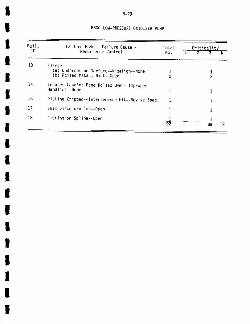
I
!
B-29
B800 LOW-PRESSURE OXIDIZER PUMP
I Fail. Failure Mode - Failure Cause - Total Criticality
IID
13 Flange
Recurrence Control No. I 2 3 N
i
I
I
I
14
16
17
18
(a) Undercut on Surface--Misalign--None(b) Raised Metal, Nick--Open
Inducer Leading Edge Rolled Over--Improper
Handling--None
Plating Chipped--Interference Fit--Revise Spec.
Shim Discoloration--Open
Pitting on Spline--Open
i
2
1
i
1
I92 89 3
I
I
I
i
II
i
Ii
I
I
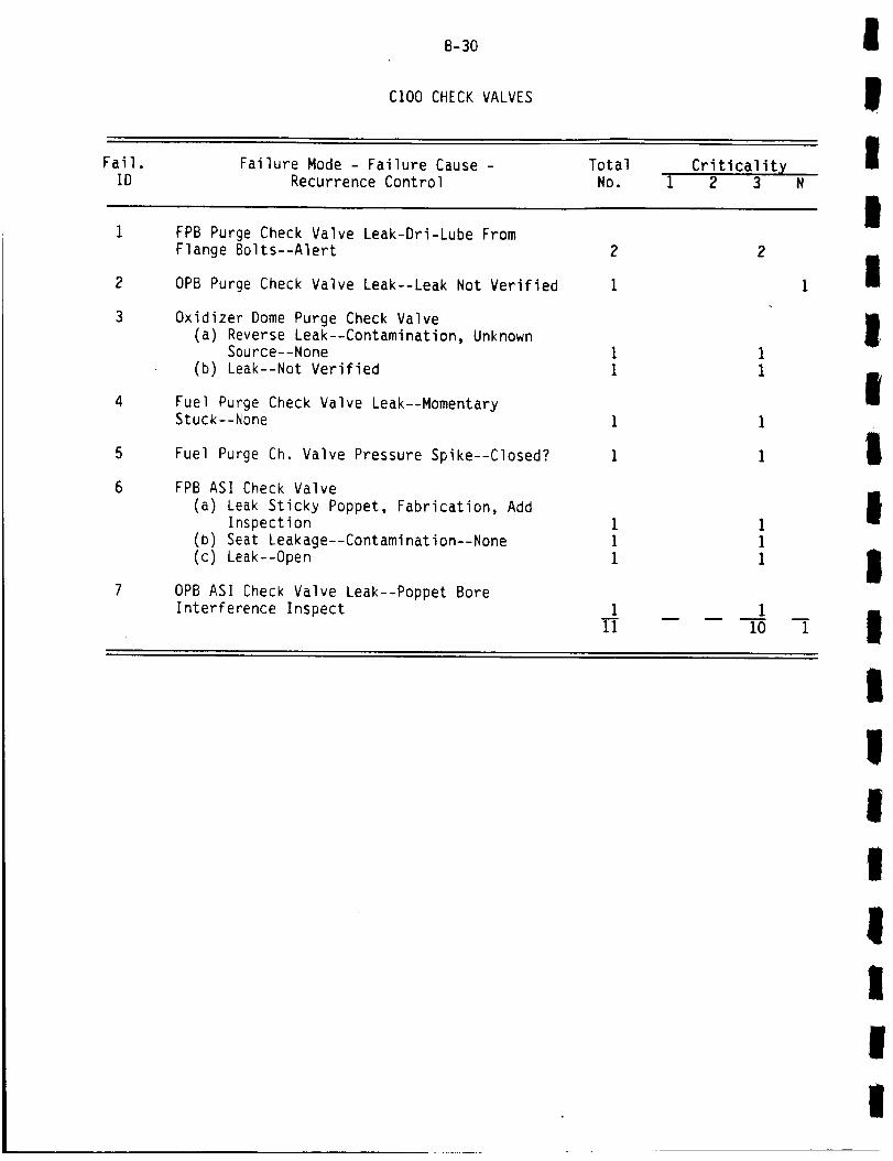
Fail.
B-30
CI00 CHECK VALVES
Failure Mode - Failure Cause - Total
I
II
ID Recurrence Control NO.Criticality
1 2 3
FPB Purge Check Valve Leak-Dri-Lube From
!Flange Bolts--Alert
OPB Purge Check Valve Leak--Leak Not Verified
Oxidizer Dome Purge Check Valve
(a) Reverse Leak--Contamination, UnknownSource--None
(b) Leak--Not Verified
Fuel Purge Check Valve Leak--MomentaryStuck--None
Fuel Purge Ch. Valve Pressure Spike--Closed?
FPB ASI Check Valve
(a) Leak Sticky Poppet, Fabrication, Add
Inspection
(b) Seat Leakage--Contamination--None(c) Leak--Open
OPB ASI Check Valve Leak--Poppet BoreInterference Inspect 1
111
i0
2
1
D
i
i
II
III
II
IIi
Ii
II
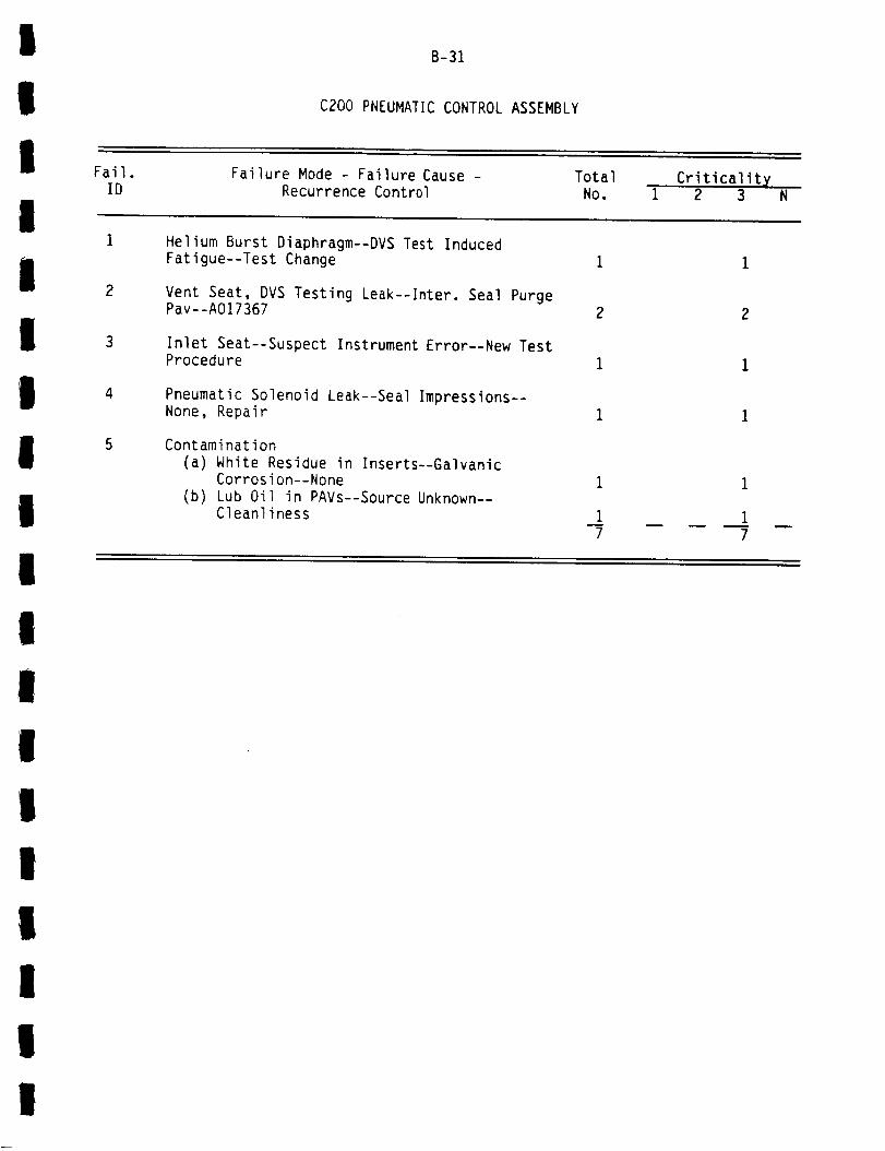
I
II
Fail.
B-31
C200 PNEUMATIC CONTROL ASSEMBLY
Failure Mode - Failure Cause - Total Criticality
IID Recurrence Control No. 1 2 3 N
i
Il
III
2
3
4
Helium Burst Diaphragm--DVS Test Induced
Fatigue--Test Change
Vent Seat, DVS Testing Leak--Inter. Seal PurgePav--A017367 2
Inlet Seat--Suspect Instrument Error--New TestProcedure
Pneumatic Solenoid Leak--Seal Impressions--None, Repair
Contamination
(a) White Residue in Inserts--GalvanicCorrosion--None
(b) Lub Oil in PAYs--Source Unknown--Cleanliness
i
1
7
1
7
I
i
I
II
I
I
II
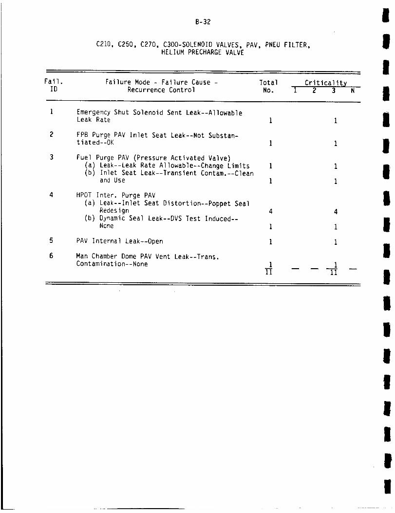
B-32
C210, C250, C270, C300-SOLENOID VALVES, PAV, PNEU FILTER,HELIUM PRECHARGEVALVE
I
II
Fail.ID
Failure Mode - Failure Cause -Recurrence Control
Total
No.Criticality
1 2 3 N I
5
6
Emergency Shut Solenoid Sent Leak--AllowableLeak Rate
FPB Purge PAV Inlet Seat Leak--Not Substan-tiated--OK
Fuel Purge PAV (Pressure Activated Valve)(a) Leak--Leak Rate Allowable--Change Limits(b) Inlet Seat Leak--Transient Contam.--Clean
and Use
HPOT Inter. Purge PAV
(a) Leak--Inlet Seat Distortion--Poppet SealRedesign
(b) Dynamic Seal Leak--DVS Test Induced--None
PAV Internal Leak--Open
Man Chamber Dome PAV Vent Leak--Trans.Contamination--None
4
I
i
III II
1
I
I
I
I
I
I1
I
II
II
II

I
iI Fail.
B-33
Dl10 MAIN FUEL VALVE
Failure Mode - Failure Cause - Total
IID
Leaks
Recurrence Control No.Criticalit X
1 2 3
I
I
I
III
Il
I
!
4
5
6
(a) Ball Seal Leak--Scaling Factor Error--Person Alerted
(b) Valve to Actuator Misclock--Change toStd. Height Blind Tooth
(c) Internal--Suspect Contamination--NotDetermined
(d) Ball Seal Leak, Downstream Temp High--Contaminated--Leak Check
(e) Leak, Static Seal--Defect--IsolatedIncident
(f) Primary Seal Leak--Dri--Film Particles--None
Throat Sleeve Nicks--No Problem
Housing Crack--Thermal Stress @ Mfg.--AddInspection
Metal Contamination--Unknown Source--None
Bearing
(a) Washer Damage__V_+_^- _-_ ....
None, Isolated
(b) Race Cracked--Not Determined Why
Plating Separation--Handling Damage--Material Change
Broken Cam Follower Guide--Cryogenic Temp.--None I
15 14m
1
I
!
I
!
I

Fail.
B-34
D120 MAIN OXIDIZER VALVE
Failure Mode - Failure Cause - Total
I
!I
ID
Leaks
Recurrence Control NO.Criticality
1 2 3 N
I(a) Deformed Bellow--Unknown--None, Isolated
Case(b) Ball Seal Leak--Contamination--Unknown
Source--None(c) Ball Seal Leak--Dri-Lube on Surface--OK(d) Ball Seal Leak Installation Position
Marginal--Redesign
i
i1
1
2Inlet Discharge Sleeves Nicked--Debris--OK
Bearing Retainer Hub Broke--Fatigue--Mov Spec. Change 2
IContamination Source Unknown--Inspection
Follow Guide Omitted in Assembly--Mfg.Oversight--Notify Person
Drift Open Installation Error Procedures
Change
Bearing, Rusty--Isolated Case--None
Excessive Pressure @ Hotfire--UCR A008305
Water in Joint 07--Inadequate Closure--New Closure I
14 13
I
11
1
1 1
i
III
III
I
II
II
Ii
I
I

!
!
B-35
D130 FUEL PREBURNEROXIDIZER VALVE
I Fail. Failure Mode - Failure Cause - Total Criticalit X
IID Recurrence Control No. i 2 3 N
Leaks--Ball Seal
I
!i
I
II
I
l
2
(a) Ball Seal Leak--Particle Contamination,Unknown--None
(b) Leak--Cracked Ball Seal, Poor Material
Spec. Change
(c) Leak--Discrepant Bellows--None, IsolatedCase
Leak (Other)
(a) Suspect Leak--Marginal Bellows--Spec.Change
(b) Internal Leak--Particle Backflow--
Closing Rate Change
Ball Seal Damage--ASI Combustion Backflow--Personnel Alert
Contamination--Unknown Source--None
Bolt Stretch Error Caused Low Flow Rate--
Personnel Alert
Suspect Over Pressurization--UCR A008305
Excessive Flowrate During Test--Normal
2
I
i13
2
1
2
1
1
12m
1
I
II
lIII
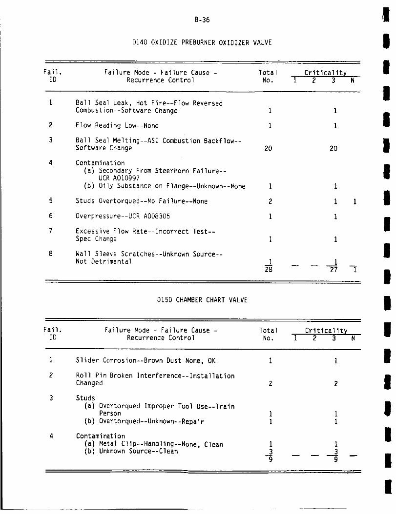
Fail.
B-36
D140 OXIDIZE PREBURNEROXIDIZER VALVE
Failure Mode - Failure Cause - Total Criticalit X
I
II
ID Recurrence Control No. 1 2 3 N
Ball Seal Leak, Hot Fire--Flow Reversed
ICombustion--Software Change i
Flow Reading Low--None 1
Ball Seal Melting--ASl Combustion Backflow--Software Change 20
Contamination(a) Secondary From Steerhorn Failure--
UCR A010997
(b) Oily Substance on Flange--Unknown--None I
Studs Overtorqued--No Failure--None 2
Overpressure--UCR A008305 i
Excessive Flow Rate--Incorrect Test--Spec Change I
Wall Sleeve Scratches--Unknown Source--Not Detrimental I
28
2O
27 -i
III
I
IIl
D150 CHAMBER CHART VALVE !Fail.
IDFailure Mode - Failure Cause -
Recurrence ControlTotal
No.
Slider Corrosion--Brown Dust None, OK
Criticality1 2 3
I!
2
3
4
Roll Pin Broken Interference--Installation
Changed
Studs
(a) Overtorqued Improper Tool Use--TrainPerson
(b) Overtorqued--Unknown--Repai r
Contamination
(a) Metal Clip--Handling--None, Clean(b) Unknown Source--Clean
I39
I
IlI!

I
!
B-37
D200 BLEED VALVE
II
I
Fail.ID
1
Failure Mode - Failure Cause -
Recurrence ControlTotal
No.Criticalitx
1 2 3
Leak--Isolated Incident--None 2 2
I!
LVDT VoltageRedesign
Oscillation--Vibration, Fatique--2
4
2
4
ID300 ANTIFLOOD VALVE
IFail.
IDFailure Mode - Failure Cause -
Recurrence ControlTotal
No.Criticalitx
1 2 3
IIi
I
II
i
III
LVDT & Wiring
(a) Output Voltage Low--Wire Fatigue--Spec. Change
(b) Output Voltage Low-Handling Damage--None
(c) Position Signal Eratic--Broken Probe,Vibs--None
(d) Open Circuit-_High Cycle Fatigue--Hys Fillet Increased
(e) Erratic Position Indication--BrokenWire--UCR A012535
(f) Erratic Position Indication--Open
Poppet
(a) Cracked Suspect
(b) Cracked--OpenHandling--Assembly Change
Separation @ Weld--Defective--Weld ScheduleReview
Piston Spring Broke--High Cycle Fatigue--Redesign
Valve Remained Open @ Shutdown--Not Lodged--Inspection Alerted
Indicator Bolts Incorrect Type--Supplied--Notified
Contamination
(a) Particle--Tapping Debris--InspectionAdded
(b) Source Unknown--Cleanliness
i
2
18I
2 1
2
2
1
2
1
1
2
15
I
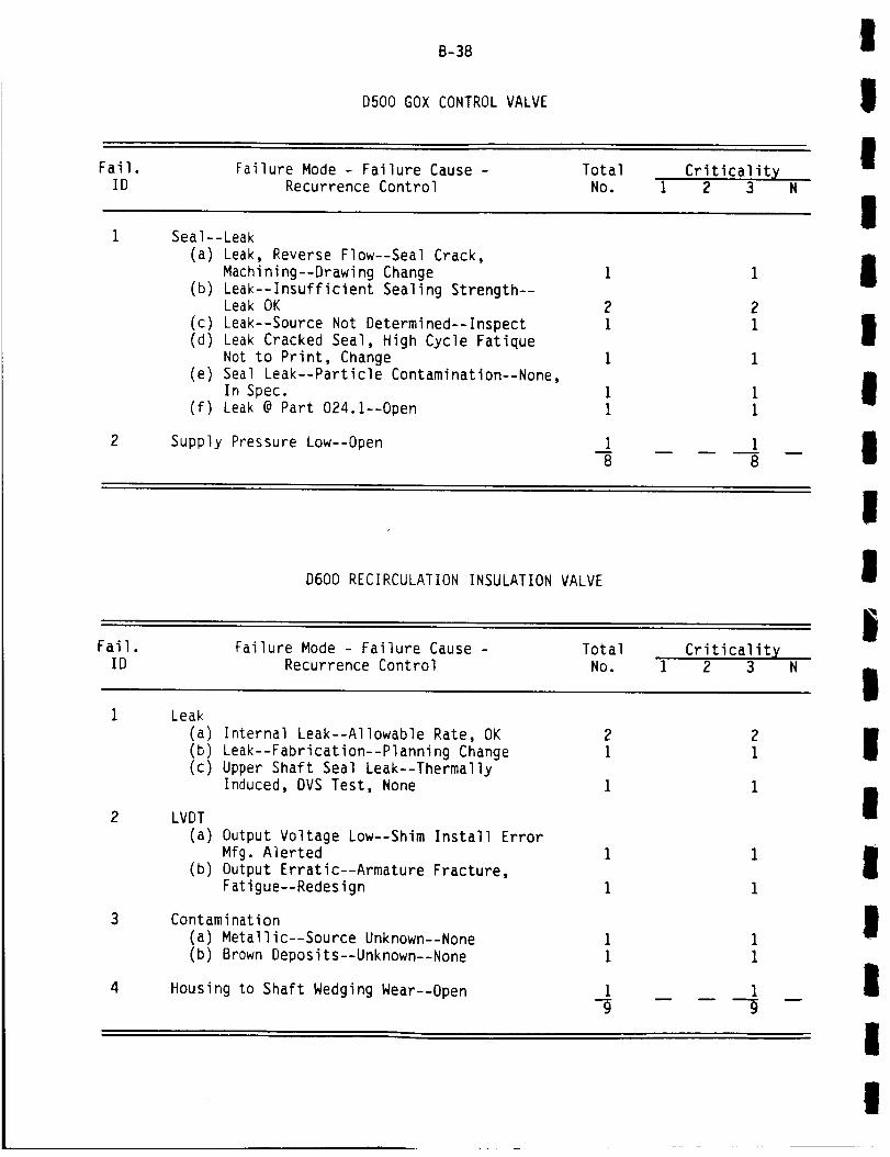
Fail.
B-38
D500 GOX CONTROL VALVE
Failure Mode - Failure Cause - Total Criticality
I
!II
ID Recurrence Control No. 1 2 3 N
I
2
Seal--Leak
(a) Leak, Reverse Flow--Seal Crack,
Machining--Drawing Change(b) Leak--Insufficient Sealing Strength--
Leak OK
(c) Leak--Source Not Determined--Inspect
(d) Leak Cracked Seal, High Cycle Fatique
Not to Print, Change(e) Seal Leak--Particle Contamination--None,
In Spec.
(f) Leak @ Part 024.1--Open
Supply Pressure Low--Open
1
2
1
1
1
1
1
8
1
2
1
1
11
i
8
II
II
D600 RECIRCULATION INSULATION VALVE
II
iFail.
IDFailure Mode - Failure Cause -
Recurrence ControlTotal
No.Criticality
1 2 3
!
2
3
4
Leak(a) Internal Leak--Allowable Rate, OK(b) Leak--Fabrication--Planning Change(c) Upper Shaft Seal Leak--Thermally
Induced, DVS Test, None
2i
LVDT
(a) Output Voltage Low--Shim Install Error
Mfg. Alerted
(b) Output Erratic--Armature Fracture,
Fatigue--Redesign
Contamination
(a) Metallic--Source Unknown--None
(b) Brown Deposits--Unknown--None
Housing to Shaft Wedging Wear--Open I9
IIi
III
I
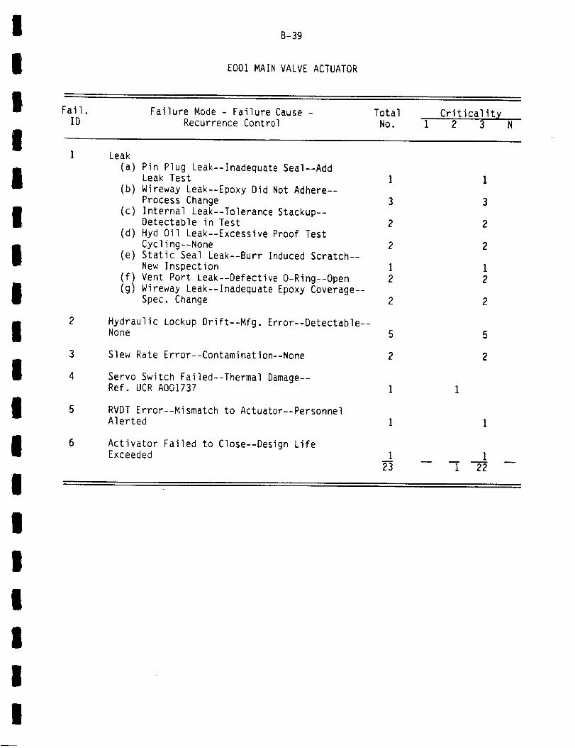
!
!
! Fail.
B-39
EO01 MAIN VALVE ACTUATOR
Failure Mode - Failure Cause - Total
!ID Recurrence Control NO.
Criticality1 2 3 N
I
I
I
III
II
I
Leak(a) Pin Plug Leak--Inadequate Seal--Add
Leak Test(b) Wireway Leak--Epoxy Did Not Adhere--
Process Change(c) Internal Leak--Tolerance Stackup--
Detectable in Test(d) Hyd Oil Leak--Excessive Proof Test
Cycling--None(e) Static Seal Leak--Burr Induced Scratch--
New Inspection(f) Vent Port Leak--Defective O-Ring--Open(g) Wireway Leak--Inadequate Epoxy Coverage--
Spec. Change
Hydraulic Lockup Drift--Mfg, Error--Detectable--None
Slew Rate Error--Contamination--None
Servo Switch Failed--Thermal Damage--Ref. UCR A001737
RVDT Error--Mismatch to Actuator--PersonnelAlerted
Activator Failed to Close--Design LifeExceeded
I
3
2
2
i2
2
5
2
I23
1
3
2
2
i2
2
5
2
1 22
II
II
II
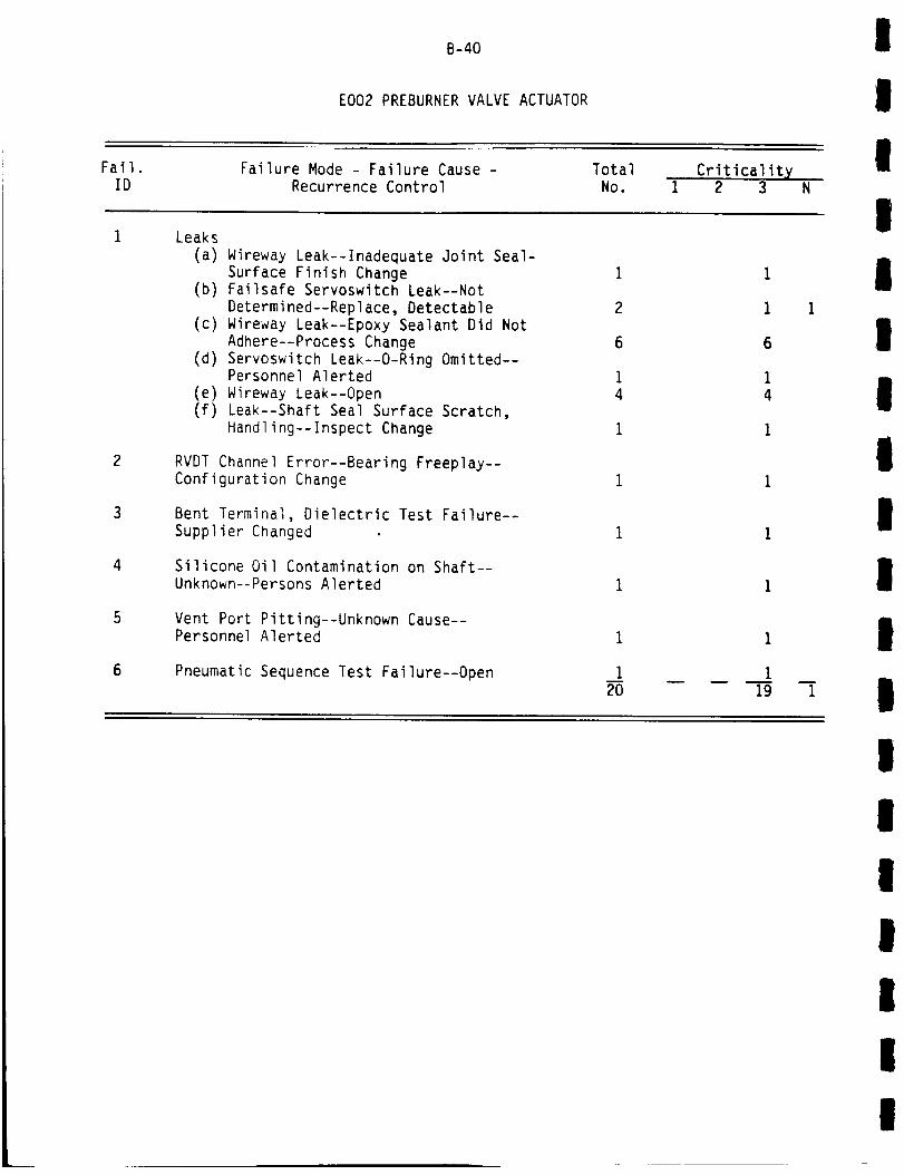
Fail.
B-40
EO02 PREBURNER VALVE ACTUATOR
Failure Mode - Failure Cause - Total Criticality
I
II
ID
Leaks
Recurrence Control No. 1 2 3 N
I(a) Wireway Leak--Inadequate Joint Seal-
Surface Finish Change(b) Failsafe Servoswitch Leak--Not
Determined--Replace, Detectable
(c) Wireway Leak--Epoxy Sealant Did Not
Adhere--Process Change(d) Servoswitch Leak--O-Ring Omitted--
Personnel Alerted
(e) Wireway Leak--Open
(f) Leak--Shaft Seal Surface Scratch,
Handling--Inspect Change
RVDT Channel Error--Bearing Freeplay--Configuration Change
Bent Terminal, Dielectric Test Failure--Supplier Changed
Silicone Oil Contamination on Shaft--
Unknown--Persons Alerted
Vent Port Pitting--Unknown Cause--Personnel Alerted
Pneumatic Sequence Test Failure--Open 120 19
1
1 1
6
14
1
1
I
I
II
III
I
1
III
III
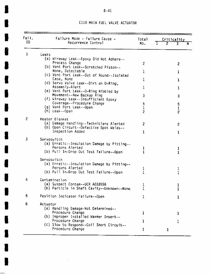
D
!
B-41
El10 MAIN FUEL VALVE ACTUATOR
!
!Fail. Failure Mode - Failure Cause - Total CriticalityID Recurrence Control No. 1 2 3 N
i Leaks
I
III
IIII
iil
I
DI
Ili
(a) Wireway Leak--Epoxy Did Not Adhere--
Process Change
(b) Vent Port Leak--Scratched Piston--None, Detectable
(c) Vent Port Leak--Out of Round--IsolatedCase, None
(d) Servo Valve Leak--Dirt on O-Ring,
Assembly-Alert
(e) Vent Port Leak--O-Ring Nibbled byMovement--New Backup Ring
(f) Wireway Leak--Insufficient Epoxy
Coverage--Procedure Change(g) Vent Port Leak--Open
(h) Leak--Open
Heater Blanket
(a) Damage Handling--Technicians Alerted
(b) Open Circuit--Defective Spot Welds--
Inspection Added
Servoswitch
(a) Erratic--Insulation Damage by Pitting--Persons Alerted
(b) Pull In-Drop Out Test Failure--Open
Servoswitch
(a) Erratic--Insulation Damage by Pitting--Persons Alerted
(b) Pull In-Drop Out Test Failure--Open
4 Contamination(a) Suspect Contam--UCR A018556(b) Particle in Shaft Cavity--Unknown--None
5 Position Indicator Failure--Open
6 Actuator
(a) Handling Damage-Not Determined--Procedure Change
(b) Improper Installed Warmer Insert--
Procedure Change(c) Slow to Respond--Coil Short Circuit--
Procedure Change
2 2
1 1
i I
1 1
3 3
5 5i I2 2
2 2
i i
1 11 1
1 11 1
1 11 1
1 1
1 1
1 1
1 1
!
!

B-42
El10 MAIN FUEL VALVE ACTUATOR (CONTINUED)
!
!Fail.
IDFailure Mode - Failure Cause -
Recurrence ControlTotal
No.Criticalit X
1 2 3 N
Actuator to Valve Mating Proc. Error--
!
!
10
11
Wrong Instructions--New Instructions 1
Hyd. Oil Wetting @ Servo-Anomaly--Tech Alerted 1
Washer and Spring Bent--Mfg. Procedure Error--Procedure Change 1
Failsafe Performance Test Failure--Open 1
Seal Damage--Housing Fab. Error--Tech Alerted 235
1
1
1 I1 33 I
!
II
I
E120 MAIN OXIDIZER VALVE ACTUATOR
!
!Fail.
IDFailure Mode - Failure Cause -
Recurrence ControlTotal
No.Criticality
1 2 3 Ni
Leak
(a) Leak--Contamination, Source Unknown--None
(b) Hyd Oil Contaminated Induced Wear--Clean
(c) Contam. Induced Cap Seal Scratches--Source Unknown--None
(d) Leak--Housing to Actuator Cylinder--Pending Analysis
Contamination
(a) Contam.--See UCR A018556
(b) Hyd. Reservoir and Supply (Facility)--Purge Added
Wireway Nut Broken--Undetermined--None
Wire Insulation Cold Flow Marks--Vibration--Not Detrimental 1
8
l
B
giiI
Ii

I
I
I Fail.
B-43
E130 FUEL PREBURNER OXIDIZER VALVE ACTUATOR
Failure Mode - Failure Cause - Total
IID Recurrence Control No.
Criticality1 2 3 N
I
I
II
II
2
Leak
(a) Dynamic Seal--Hyd. Oil Contam. Induced
Wear--Clean and Maintain 2
(b) Seq. Valve Seal Leak--O-Ring Shift--Redesign 1
Contamination
(a) Suspect--UCR A018556 1
(b) Contam. Facility Hyd. Reservoir--
Drum Purge Added 1
Pretest Check Out FIDs--Suspect Contam.--None i
O-Ring Defect--Personnel Alerted i
Crank Failure--Obsolete Configuration--Replace 1
Sequence Valve Anomaly--Open I
9
1
1
1
1
1
11 8
I
I E140 OXIDIZER PREBURNER VALVE ACTUATOR
I
I
Fail.ID
1
Fa41ure Mode - Failure Cause -
Recurrence ControlTotalNo.
Criticality1 2 3
Forwara Servo Leak--Not Determined--OK
I
II
I
Use As Is
Contamination(a) Contamination--See UCR A018556(b) Facility Hyd. Reservoir Contam.--Drum
Purge Added
Bolts Rusty--Cosmetic Condition--Change Bolts
Actuator Would Not Close--Crank Failure,Obsolete Conf.--Replace I
5
I
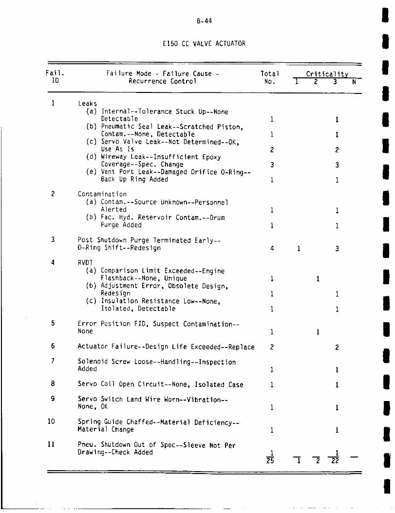
B-44
El50 CC VALVE ACTUATOR
I
IIFail.
ID
Leaks
Failure Mode - Failure Cause -Recurrence Control
TotalNo.
Criticalit X1 2 3 N
I
I0
11
(a) Internal--Tolerance Stuck Up--NoneDetectable
(b) Pneumatic Seal Leak--Scratched Piston,Contam.--None, Detectable
(c) Servo Valve Leak--Not Determined--OK,Use As Is
(d) Wireway Leak--Insufficient EpoxyCoverage--Spec. Change
(e) Vent Port Leak--Damaged Orifice O-Ring--Back Up Ring Added
Contamination(a) Contam.--Source Unknown--Personnel
Alerted(b) Fac. Hyd. Reservoir Contam.--Drum
Purge Added
Post Shutdown Purge Terminated Early--O-Ring Shift--Redesign
RVDT
(a) Comparison Limit Exceeded--Engine
Flashback--None, Unique
(b) Adjustment Error, Obsolete Design,Redesign
(c) Insulation Resistance Low--None,Isolated, Detectable
Error Position FID, Suspect Contamination--None
Actuator Failure--Design Life Exceeded--Replace
Solenoid Screw Loose--Handling--InspectionAdded
Servo Coil Open Circuit--None, Isolated Case
Servo Switch Land Wire Worn--Vibration--None, OK
Spring Guide Chaffed--Material Deficiency--Material Change
Pneu. Shutdown Out of Spec--Sleeve Not PerDrawing--Check Added
I
I
2
3
i
4
i
2
I25
i
I
1
i
2
m
1 2 22
I
II
II
II
I
I
l
I
I
III
L
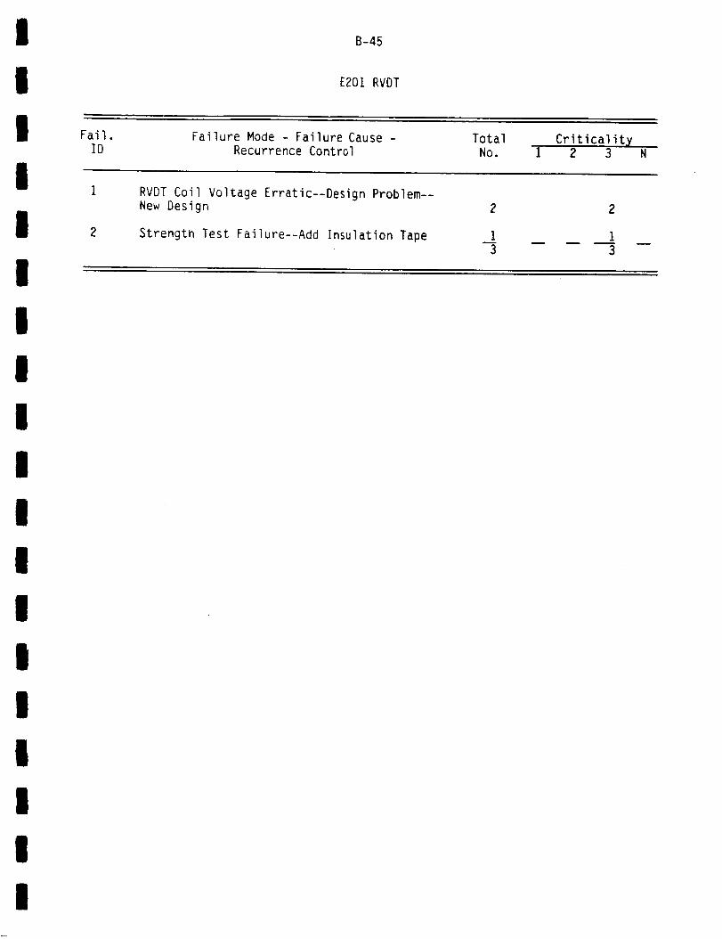
I
I
I Fail.
B-45
E201RVDT
Failure Mode - Failure Cause - Total
IID
RVDT
Recurrence Control NO.Criticalit X
1 2 3 N
Coil Voltage Erratic--Design Problem--
I
I
2
New Design
Strength Test Failure--Add Insulation Tape I3
2
1
3
I
III
I
II
II
I
I
II
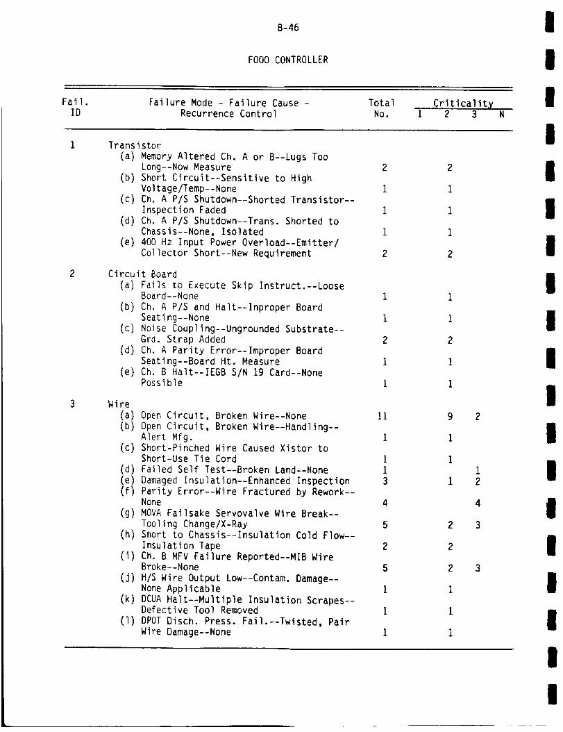
Fail.
B-46
FO00 CONTROLLER
Failure Mode - Failure Cause - Total Criticality
I
I
IID Recurrence Control No. 1 2 3 N
TransistorI
(a) Memory Altered Ch. A or B--Lugs Too
Long--Now Measure
(b) Short Circuit--Sensitive to HighVoltage/Temp--None
(c) Ch. A P/S Shutdown--Shorted Transistor--
Inspection Faded(d) Ch. A P/S Shutdown--Trans. Shorted to
Chassis--None, Isolated
(e) 400 Hz Input Power Overload--Emitter/
Collector Short--New Requirement
Circuit Board
(a) Fails to Execute Skip Instruct.--LooseBoard--None
(b) Ch. A P/S and Halt--Inproper Board
Seating--None
(c) Noise Coupling--Ungrounded Substrate--Grd. Strap Added
(d) Ch. A Parity Error--Improper Board
Seating--Board Ht. Measure(e) Ch. B Halt--IEGB S/N 19 Card--None
Possible
Wire
(a) Open Circuit, Broken Wire--None
(b) Open Circuit, Broken Wire--Handling--Alert Mfg.
(c) Short-Pinched Wire Caused Xistor toShort-Use Tie Cord
(d) Failed Self Test--Broken Land--None
(e) Damaged Insulation--Enhanced Inspection
(f) Parity Error--Wire Fractured by Rework--None
(g) MOVA Failsake Servovalve Wire Break--
Tooling Change/X-Ray(h) Short to Chassis--Insulation Cold Flow--
Insulation Tape(i) Ch. B MFV Failure Reported--MIB Wire
Broke--None
(j) H/S Wire Output Low--Contam. Damage--None Applicable
(k) DCUA Halt--Multiple Insulation Scrapes--Defective Tool Removed
(1) DPOT Disch. Press. Fail.--Twisted, PairWire Damage--None
11
1
113
4
5
2
5
1
1
1
2
1
1
1
2
9
1
I
1
2
2
2
I
1
1
2
1
2
4
3
3
I
I
I
I
I
I
II
I
I
I
I
I
I
I
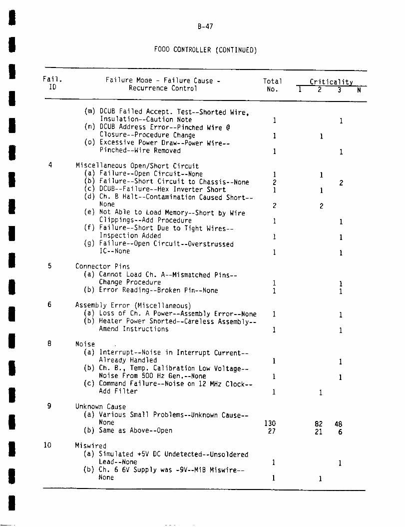
B-47
Fail.
FO00 CONTROLLER (CONTINUED)
Failure Mode - Failure Cause - Total CriticalityID Recurrence Control No. 1 2 3 N
I
I
iI
II
III
I
I
II
i
4
5
6
8
9
i0
(m) DCUB Failed Accept. Test--Shorted Wire,Insulation--Caution Note
(n) DCUB Address Error--Pinched Wire @Closure--Procedure Change
(o) Excessive Power Draw--Power Wire--Pinched--Wire Removed
Miscellaneous Open/Short Circuit(a) Failure--Open Circuit--None(b) Failure--Short Circuit to Chassis--None(c) DCUB--Failure--Hex Inverter Short(d) Ch. B Halt--Contamination Caused Short--
None(e) Not Able to Load Memory--Short by Wire
Clippings--Add Procedure(f) Failure--Short Due to Tight Wires--
Inspection Added(g) Failure--Open Circuit--Overstrussed
IC--None
Connector Pins(a) Cannot Load Ch. A--Mismatched Pins--
Change Procedure(b) Error Reading--Broken Pin--None
Assembly Error (Miscellaneous)(a) Loss of Ch. A Power--Assembly Error--None(b) Heater Power Shorted--Careless Assembly--
Amend Instructions
Noise(a) Interrupt--Noise in Interrupt Current--
Already Handled(b) Ch. B., Temp. Calibration Low Voltage--
Noise From 500 Hz Gen.--None(c) Command Failure--Noise on 12 MHz Clock--
Add Filter
Unknown Cause(a) Various Small Problems--Unknown Cause--
None(b) Same as Above--Open
Miswired(a) Simulated +5V DC Undetected--Unsoldered
Lead--None(b) Ch. 6 6V Supply was -gV--MiB Miswire--
None
13027
82
21
48
6
I
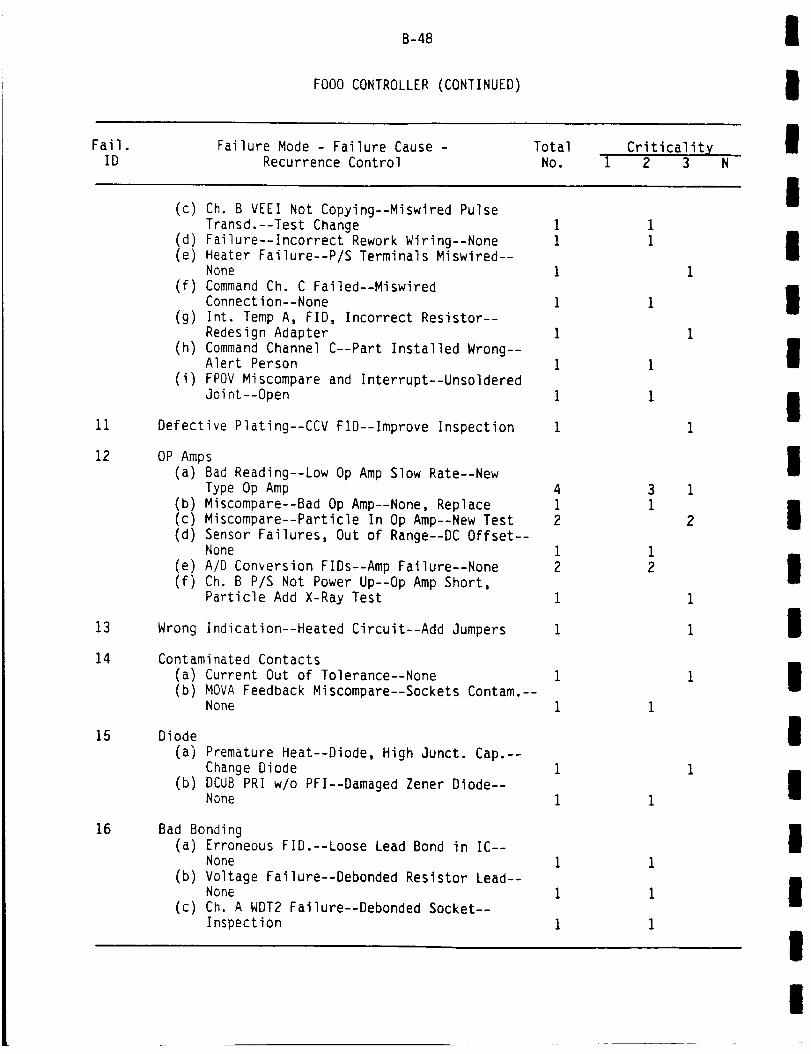
B-48
FO00 CONTROLLER (CONTINUED)
I
!
Fail.ID
Failure Mode - Failure Cause -
Recurrence Control
Total
No.Criticality
1 2 3
(c) Ch. B VEEI Not Copying--Miswired Pulse
!
I
11
12
13
14
15
16
Transd.--Test Change 1
(d) Failure--Incorrect Rework Wiring--None 1(e) Heater Failure--P/S Terminals Miswired--
None I
(f) Command Ch. C Failed--MiswiredConnection--None 1
(g) Int. Temp A, FID, Incorrect Resistor--
Redesign Adapter 1
(h) Command Channel C--Part Installed Wrong--Alert Person i
(i) FPOV Miscompare and Interrupt--Unsoldered
Joint--Open 1
1Defective Plating--CCV FiD--Improve Inspection
OP Amps
(a) Bad Reading--Low Op Amp Slow Rate--New
Type Op Amp 4
(b) Miscompare--Bad Op Amp--None, Replace 1
(c) Miscompare--Particle In Op Amp--New Test 2(d) Sensor Failures, Out of Range--DC Offset--
None 1
(e) A/D Conversion FIDs--Amp Failure--None 2(f) Ch. B P/S Not Power Up--Op Amp Short,
Particle Add X-Ray Test 1
1Wrong Indication--Heated Circuit--Add Jumpers
Contaminated Contacts
(a) Current Out of Tolerance--None 1
(b) MOVA Feedback Miscompare--Sockets Contam.--None 1
Diode
(a) Premature Heat--Diode, High Junct. Cap.--Change Diode 1
(b) DCUB PRI w/o PFI--Damaged Zener Diode--None i
Bad Bonding(a) Erroneous FID.--Loose Lead Bond in IC--
None i
(b) Voltage Failure--Debonded Resistor Lead--None 1
(c) Ch. A WDT2 Failure--Debonded Socket--Inspection I
1
1
1
I
1
1
3 11
2
12
1
I
I
1
1
I
II
II
II
I
Il
III
II
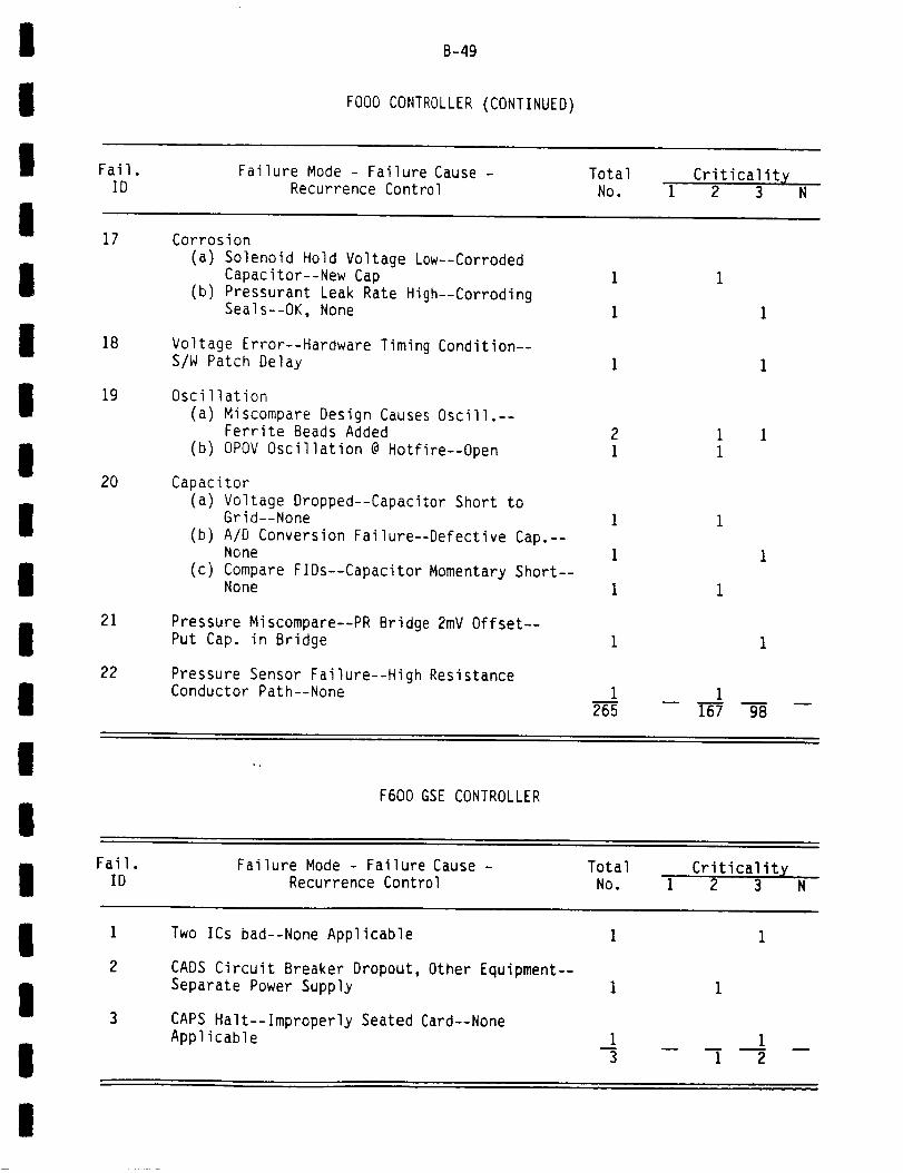
I
II Fail.
B-49
FO00 CONTROLLER (CONTINUED)
Failure Mode - Failure Cause - Total
IID
17
Recurrence Control No.Criticalit X
1 2 3 N
Corrosion
II
I
III
II
18
19
20
21
22
(a) Solenoid Hold Voltage Low--CorrodedCapacitor--New Cap
(b) Pressurant Leak Rate High--CorrodingSeals--OK, None
Voltage Error--Hardware Timing Condition--S/W Patch Delay
Oscillation
(a) Miscompare Design Causes Oscill.--Ferrite Beads Added
(b) OPOV Oscillation @ Hotfire--Open
Capacitor
(a) Voltage Dropped--Capacitor Short toGrid--None
(b) A/D Conversion Failure--Defective Cap.--None
(c) Compare FIDs--Capacitor Momentary Short--None
Pressure Miscompare--PR Bridge 2mV Offset--Put Cap. in Bridge
Pressure Sensor Failure--High ResistanceConductor Path--None I
265
i
i
I ii
1
167 98
I
IF600 GSE CONTROLLER
I Fail.ID
Failure Mode - Failure Cause -Recurrence Control
TotalNo.
Criticalit X1 2 3 N
II
I
1
2
Two ICs bad--None Applicable
CADS Circuit Breaker Dropout, Other Equipment--Separate Power Supply
CAPS Halt--Improperly Seated Card--NoneApplicable i i
3 1 2
I
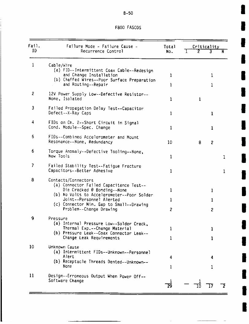
Fail.
B-50
F800 FASCOS
Failure Mode - Failure Cause - Total Criticalit X
II
IID Recurrence Control No. 1 2 3 N
Cable/WireI
2
3
4
5
6
8
9
10
11
(a) FID--Intermittent Coax Cable--Redesignand Change Installation
(b) Chaffed Wires--Poor Surface Preparation
and Routing--Repair
12V Power Supply Low--Defective Resistor--None, Isolated
Failed Propagation Delay Test--CapacitorDefect--X-Ray Caps
FIDs on Ch. 2--Short Circuit in Signal
Cond. Module--Spec. Change
FIDs--Combined Accelerometer and MountResonance--None, Redundancy
Torque Anomaly--Defective Tooling--None,New Tools
Failed Stability Test--Fatigue FractureCapacitors--Better Adhesive
Contacts/Connectors(a) Connector Failed Capacitance Test--
Die Cracked @ Bonding--None(b) No Volts to Accelerometer--Poor Solder
Joint--Personnel Alerted
(c) Connector Min. Gap to Small--DrawingProblem--Change Drawing
Pressure
(a) Internal Pressure Low--Solder Crack,
Thermal Exp.--Change Material(b) Pressure Leak--Coax Connector Leak--
Change Leak Requirements
Unknown Cause(a) Intermittent FIDs--Unknown--Personnel
Alert(b) Receptacle Threads Dented--Unknown--
None
Design--Erroneous Output When Power Off--
Software Change
10
I
29
8 2
2
I
II
II
II
l
II
III
II

I
!! Fail.
B-51
GOO0 IGNITER
Failure Mode - Failure Cause - Total Criticalit X
IID Recurrence Control No. i 2 3 N
Ignitor Tip Cracks
II
II
II
II
II
I
Il
I
2
3
4
5
6
7
8
9
10
(a) Surface Cracks--Extended Service--OK,Normal
(b) Copper Tip Damage--Extended Service--Past Design Life
(c) Output Failure--Suspect PhysicalDamage--None
Igniter Tip Erosion(a) Tip Erosion--Off Combustion, ASI
Contamination--OK As Is
(b) Tip Erosion--Off Normal Combustion--None, Replace
No Spark--Contamination (ASl)--None OK As Is
Igniter Tip Melting--ASl Contamination--OK As Is
Insulator Crack(a) Cracked Ceramic--ASl Contamination--
None, OK As Is(b) Ceramic Flaking--Off Normal Combustion--
Repair or Replace(c) Ceramic Failure--Spark Quenches--
Add Criteria
Electric Connections(a) Output Voltage Off--Bad Connection--
Isolated, None(b) Ch. B Igniter Malfunction--Inadequate
Ground--Mfg. Process Change(c) Intermittent--Internal Ground Strap
Not Attached--Mfg. Notified
Igniter Tip--Moisture(a) Spark Failure--Moisture on Tip--Drying
Procedure
(b) FID During Checkout--Moisture--None
Intermittent--Transformer Short, Void-
Change Mfg.
Monitor Voltage High--Transistor Failed--None, Detectable
Igniter Tip Debonding--Plating Deficiency--Mfg. Improved
13
8
I
ii
6
i
22
1
1
2
7
6
1
2
2
6
4
I

Fail.
B-52
GO00 IGNITER (CONTINUED)
Failure Mode - Failure Cause - Total Criticality
I
II
ID Recurrence Control No. 1 2 3 N
I11
12
13
14
15
Cause Unknown--Various
(a) Erratic Output--Cause Unknown--None
(b) Low Insulator Resistance--Suspect--Spec. Change
Potting Void--Erratic Operation--Mfg. ProcessChange
Low Resistance Pin--F2 Filter Failed--ChangeCleaning Solvent
Output Failure, Electrode Short-OffCombustion--None
Quench Problem--Off Normal Combustion--None
i
276
2
6
4
2
1
2
62n
14
III
I
II
II
I
II
II
II
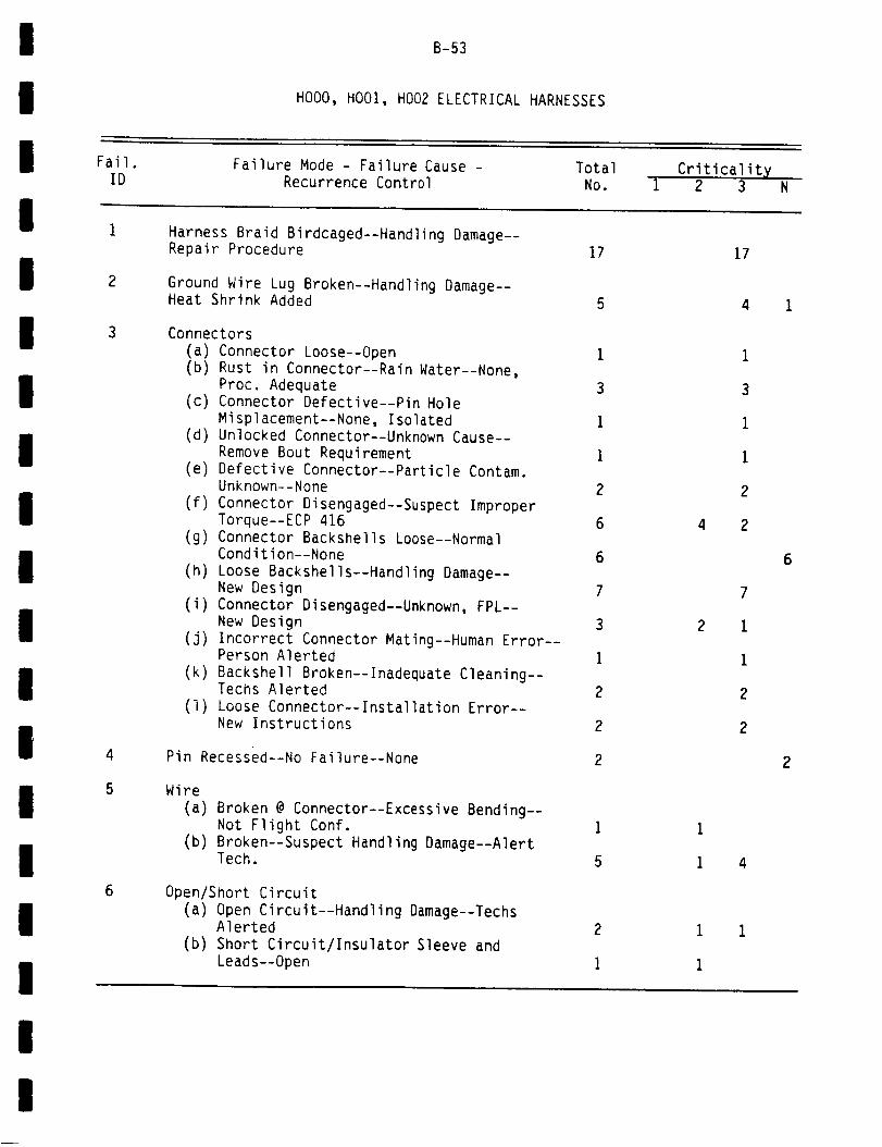
!
i
B-53
HO00, HO01, HO02 ELECTRICAL HARNESSES
i Fail. Failure Mode - Failure Cause - Total CriticalityID Recurrence Control No. I 2 3 N
!Harness Braid Birdcaged--Handling Damage--
II
I
III
II
!
II
!
I
2
3
4
5
6
Repair Procedure
Ground Wire Lug Broken--Handling Damage--Heat Shrink Added
Connectors(a) Connector Loose--Open I(b) Rust in Connector--Rain Water--None,
Proc. Adequate 3(c) Connector Defective--Pin Hole
Misplacement--None, Isolated i(d) Unlocked Connector--Unknown Cause--
Remove Bout Requirement I(e) Defective Connector--Particle Contam.
Unknown--None 2(f) Connector Disengaged--Suspect Improper
Torque--ECP 416 6(g) Connector Backshells Loose--Normal
Condition--None 6(h) Loose Backshells--Handling Damage--
New Design 7(i) Connector Disengaged--Unknown, FPL--
New Design 3(j) Incorrect Connector Mating--Human Error--
Person Alerted i(k) Backshell Broken--Inadequate Cleaning--
Techs Alerted 2(I) Loose Connector--Installation Error--
New Instructions 2
2Pin Recessed--No Failure--None
Wire(a) Broken @ Connector--Excessive Bending--
Not Flight Conf. i(b) Broken--Suspect Handling Damage--Alert
Tech. 5
Open/Short Circuit(a) Open Circuit--Handling Damage--Techs
Alerted(b) Short Circuit/Insulator Sleeve and
Leads--Open
17 17
5 4 1
1
3
1
1
2
4 2
7
2 i
i
2
2
1
1 4
1 i
i
6
!!

B-54
HO00, HO01, HO02 ELECTRICAL HARNESSES (CONTINUED)
I
II
Fail.ID
Failure Mode - Failure Cause -Recurrence Control
TotalNo.
Criticality1 2 3
I
8
9
10
11
12
13
14
15
Improper Harness Support--Support Require-ments Added
Torque Lock
(a) Debonded--Surface Contamination--None,Isolated Case
(b) Missing--Defective Material--NewMaterial
(c) Missing Connector Loose--InadequateTorque--Increase Torque
(d) Torque Lock Debonded--Bad Surface
Preparation--Spec. Change
Birdcaged @ Connector
(a) Birdcaged--Not Determined--None, Repair
(b) Birdcaged--Handling Damage--None, Repair
Loss of Continuity--Handling Damage--PersonnelAlerted
Retainer Ring
(a) Broken--Stress Corrosion--No FunctionalProblem
(b) Retainer Cracked--Stress Corrosion--
Redesign
Undetermined Problems
(a) FIDs @ Flight Readiness Test--Unknown--None Applicable
(b) Noisy, Low Signal--Unknown--Field SigntsNotified
Insulation Low Resistance--Moisture inConnector--None
Material/Elastomer Problems
(a) Material Moisture Contam.--New Supplier(b) Elastomer Abnormal--Humid Environment--
Spec. Change
(c) Material Defective--Moisture Sensitivity--
New Packaging
I
2
3
Broken Strain Relict Rope--Hardened byEpoxy--Mfg. Notified i
105 15
1
2
2
6
14
2
1
2
3
77
III
I
II
I
II
II
IIII
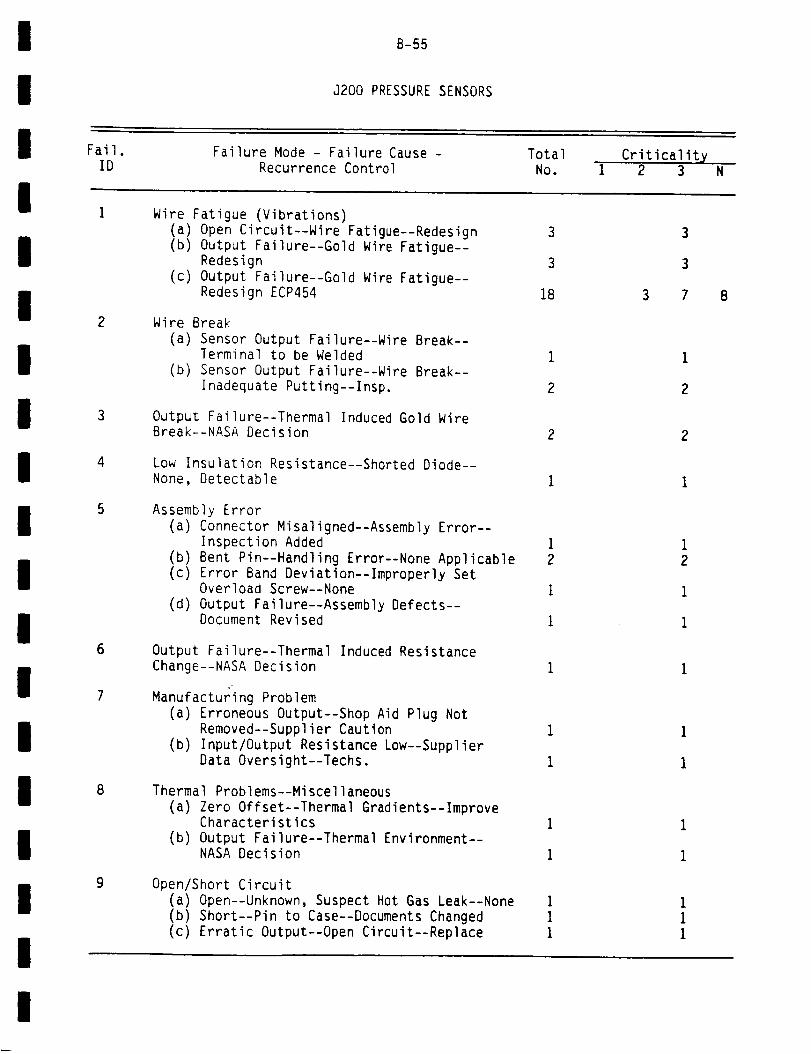
I
I
I Fail.
B-55
J200 PRESSURESENSORS
Failure Mode - Failure Cause -
iID Recurrence Control
Total Criticalit XNo. 1 2 3
Wire Fatigue (Vibrations)
II
I
III
II
I
II
I
II
2
3
4
5
6
7
8
9
(a) Open Circuit--Wire Fatigue--Redesign(b) Output Failure--Gold Wire Fatigue--
Redesign
(c) Output Failure--Gold Wire Fatigue--Redesign ECP454
Wire Break
(a) Sensor Output Failure--Wire Break--Terminal to be Welded
(b) Sensor Output Failure--Wire Break--Inadequate Putting--Insp.
Output Failure--Thermal Induced Gold WireBreak--NASA Decision
Low Insulation Resistance--Shorted Diode--None, Detectable
Assembly Error(a) Connector Misaligned--Assembly Error--
Inspection Added(b) Bent Pin--Handling Error--None Applicable(c) Error Band Deviation--Improperly Set
Overload Screw--None(d) Output Failure--Assembly Defects--
Document Revised
Output Failure--Thermal Induced ResistanceChange--NASA Decision
Manufacturing Problem(a) Erroneous Output--Shop Aid Plug Not
Removed--Supplier Caution(b) Input/Output Resistance Low--Supplier
Data Oversight--Techs.
Thermal Problems--Miscellaneous
(a) Zero Offset--Thermal Gradients--ImproveCharacteristics
(b) Output Failure--Thermal Environment--NASA Decision
Open/Short Circuit(a) Open--Unknown, Suspect Hot Gas Leak--None(b) Short--Pin to Case--Documents Changed(c) Erratic Output--Open Circuit--Replace
3
3
18
i
2
2
i2
I
i
8
I
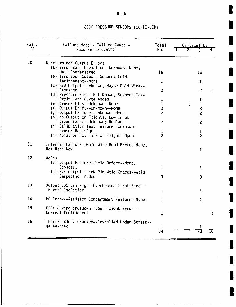
B-56
J200 PRESSURE SENSORS (CONTINUED)
I
II
Fail.ID
Failure Mode - Failure Cause -Recurrence Control
Total
No.Criticality
i 2 3 N
I10
11
12
13
14
15
16
Undetermined Output Errors(a) Error Band Deviation--Unknown--None,
Unit Compensated
(b) Erroneous Output--Suspect ColdEnvironment--None
(c) Bad Output--Unknown, Maybe Gold Wire--
Redesign(d) Pressure Rise--Not Known, Suspect Ice-
Drying and Purge Added(e) Sensor FIDs--Unknown--None(f) Output Drift--Unknown--None
(g) Output Failure--Unknown--None
(n) No Output on Flights, Low Input
Capacitance--Unknown; Replace(i) Calibration Test Failure--Unknown--
Sensor Redesign
(j) Noisy or Hot Fire or Flight--Open
Internal Failure--Gold Wire Bond Parted None,Not Used Now
Welds(a) Output Failure--Weld Defect--None,
Isolated(b) Bad Output--Link Pin Weld Cracks--Weld
Inspection Added
Output 100 psi High--Overheated @ Hot Fire--Thermal Isolation
RC Error--Resistor Compartment Failure--None
FIDs During Shutdown--Coefficient Error--Correct Coefficient
Thermal Block Cracked--Installed Under Stress--QA Advised
16
i
3
ii32
2
i2
184 4
16
1
2
1
3
2
2
1
2
70
1
1
10
II
II
II
II
I
II
II
II

I
I
B-57
J300 TEMPERATURE SENSORS
I Fail.ID
Failure Mode - Failure Cause -
Recurrence Control
Total
No.Criticality
1 2 3 N
II
I
II
II
III
I
I
II
I
1
2
3
6
Sensor Tip Erosion--Suspect Contamination--
Improved Cleaning
Sensor Tip Broken/Damage
(a) Tip Broken--Hot Gas Flow Impact--
Redesign Pending(b) Tip Bent--Over Temp.--None Applicable
(c) Erroneous Output--Flow Debris Impact--Shield Added
(d) Tip Broken--High Flow Velocity--ProbeRetracted
(e) Sensor Tip Broken--Vibration, Fatigue--Redesign
(f) Erratic Output--High Cycle Fatigue--Check Added
Output Problem--Unknown Cause(a) Erratic Output--Unknown--None
(b) Output Failure, Cracks in Pressure Seal--
Unknown--Redesign
(c) Erroneous Output--Open
Open/Short Circuit (Miscellaneous)
(a) Open Circuit--Handling Damage--PersonnelAlerted
(b) Open Circuit--Suspect Debris Impact--None
(c) Erroneous Output--Open
Open/Short Circuit (Miscellaneous)
(a) Open Circuit--Handling Damage--PersonnelAler%ed
(b) Open Circuit--Suspect Debris Impact--None
(c) Short to Case @ Test--Overheat--TechsAlerted
(d) Off Scale Output--Circuit Not Isolated--
Redesign
(e) Short Circuit--Open
Erratic Output--Braze joint Defects--CheckAdded
Insulation
(a) Open Circuit--Fatigue, Sheathing Contam.--
Redesign(b) Low Insulation Resistance--Moisture--None
(c) Low Insulation Resistance--Overheating--None
(d) Isolation Insulation Test Failure--Open
4
1
7
i
4
1
15
1i
I
i
1
4
1
1 3
1
2 5
1
4
12
11
I
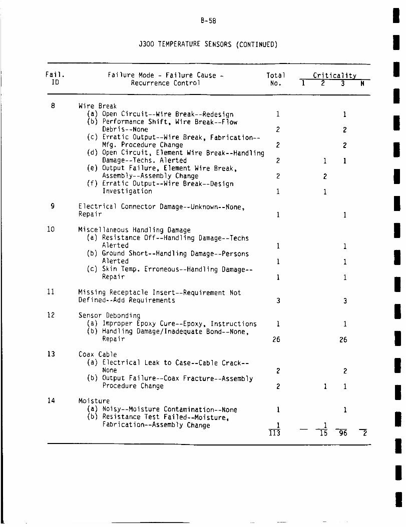
Fail.
B-5B
J300 TEMPERATURE SENSORS (CONTINUED)
Failure Mode - Failure Cause - Total
II
IID Recurrence Control No.
Criticalit X1 2 3
Wire BreakI
10
11
12
13
14
(a) Open Circuit--Wire Break--Redesign 1(b) Performance Shift, Wire Break--Flow
Debris--None 2
(c) Erratic Output--Wire Break, Fabrication--
Mfg. Procedure Change 2
(d) Open Circuit, Element Wire Break--HandlingDamage--Techs. Alerted 2
(e) Output Failure, Element Wire Break,Assembly--Assembly Change 2
(f) Erratic Output--Wire Break--DesignInvestigation 1
Electrical Connector Damage--Unknown--None,Repair
Miscellaneous Handling Damage
(a) Resistance Off--Handling Damage--TechsAlerted 1
(b) Ground Short--Handling Damage--PersonsAlerted 1
(c) Skin Temp. Erroneous--Handling Damage--Repair i
Missing Receptacle Insert--Requirement NotDefined--Add Requirements
Sensor Debonding(a) Improper Epoxy Cure--Epoxy, Instructions 1(b) Handling Damage/Inadequate Bond--None,
Repair 26
Coax Cable
(a) Electrical Leak to Case--Cable Crack--None 2
(b) Output Failure--Coax Fracture--AssemblyProcedure Change 2
Moisture
(a) Noisy--Moisture Contamination--None
(b) Resistance Test Failed--Moisture,
Fabrication--Assembly Change
1
1
113
1
2
2
1
1
26
2
1 1
1
I15 96
m
2
I
II
II
II
I
II
III
II
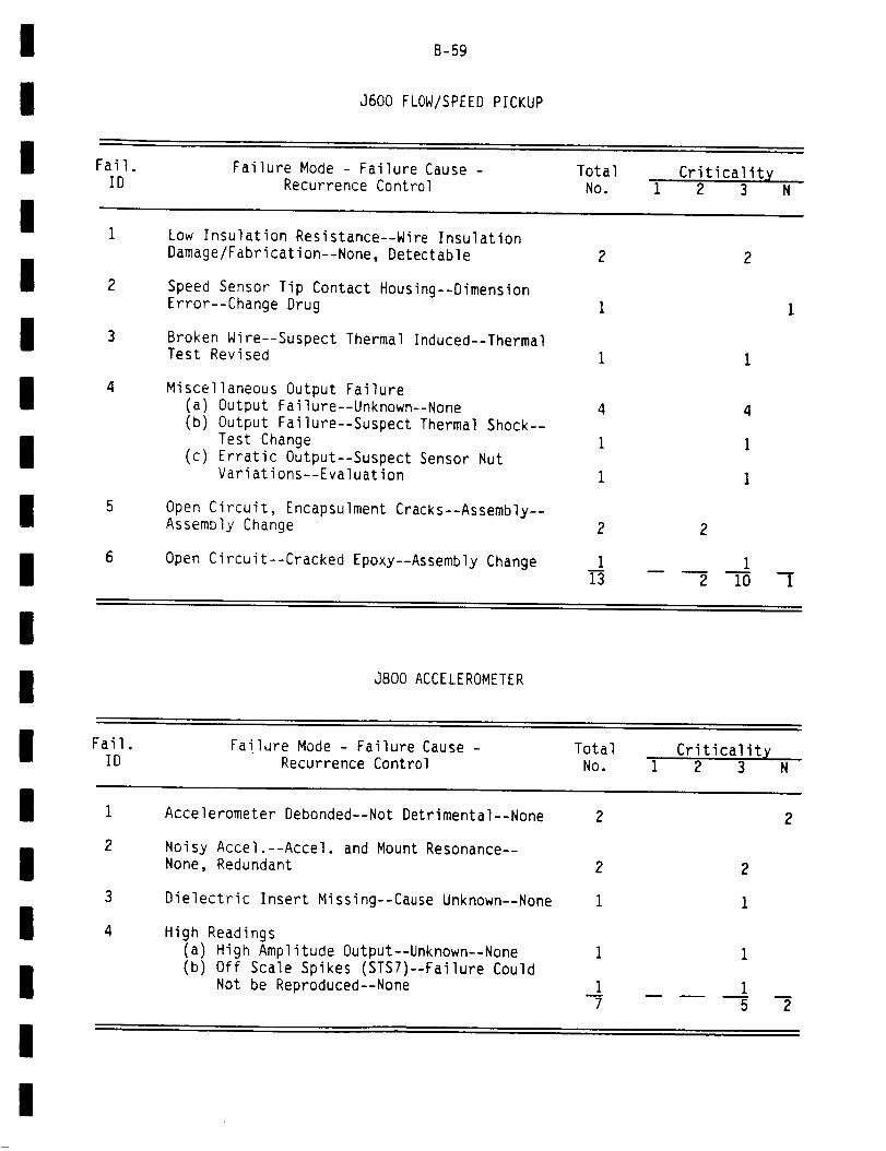
B-59
J600 FLOW/SPEED PICKUP
! Fail. Failure Mode - Failure Cause - Total Criticalitx
iID Recurrence Control No. 1 2 3 N
Low Insulation Resistance--Wire Insulation
I
Ii
II
I
2
3
4
5
6
Damage/Fabrication--None, Detectable
Speed Sensor Tip Contact Housing--DimensionError--Change Drug
Broken Wire--Suspect Thermal Induced--ThermalTest Revised
Miscellaneous Output Failure(a) Output Failure--Unknown--None
(b) Output Failure--Suspect Thermal Shock--
Test Change(c) Erratic Output--Suspect Sensor Nut
Variations--Evaluation
Open Circuit, Encapsulment Cracks--Assembly--Assembly Change
Open Circuit--Cracked Epoxy--Assembly Change
2 2
1 1
4 4
1 1
1 1
2 2
1 113 2 i0 1
i
| J800 ACCELEROMETER
i Fail. Failure Mode - Failure Cause - Total CriticalitxID Recurrence Control No. I 2 3 N
I
II
I
3
4
Accelerometer Debonded--Not Detrimental--None 2
Noisy Accel.--Accel. and Mount Resonance--None, Redundant
Dielectric Insert Missing--Cause Unknown--None
High Readings
(a) High Amplitude Output--Unknown--None I(b) Off Scale Spikes (STS7)--Failure Could
Not be Reproduced--None i7
2 2
i I
2
!
!
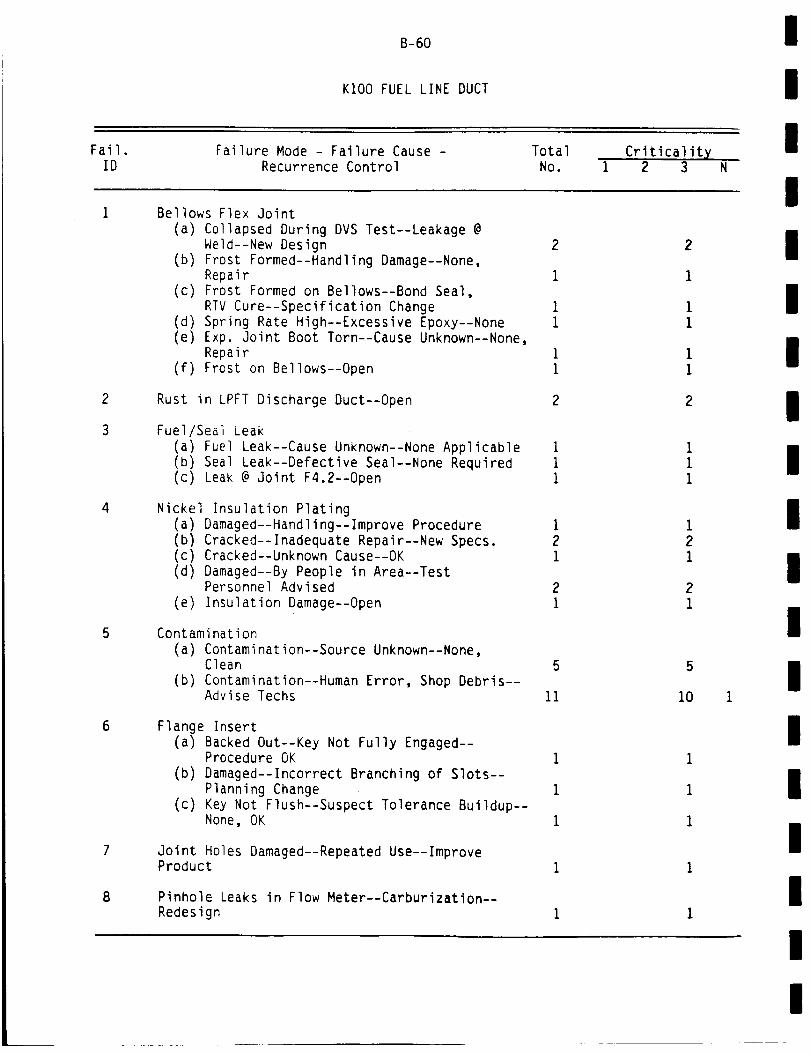
B-60
KIO0 FUEL LINE DUCT
I
IIFail.
IDFailure Mode - Failure Cause -
Recurrence ControlTotal
No.Criticalit X
1 2 3
IBellows Flex Joint
(a) Collapsed During DVS Test--Leakage @Weld--New Design
(b) Frost Formed--Handling Damage--None,Repair
(c) Frost Formed on Bellows--Bond Seal,RTV Cure--Specification Change
(d) Spring Rate High--Excessive Epoxy--None(e) Exp. Joint Boot Torn--Cause Unknown--None,
Repair(f) Frost on Bellows--Open
2
I
11
I1
2
I11
I21
21
5
11
Rust in LPFT Discharge Duct--Open
Fuel/Seal Leak(a) Fuel Leak--Cause Unknown--None Applicable(b) Seal Leak--Defective Seal--None Required(c) Leak @ Joint F4.2--Open
Nickel Insulation Plating(a) Damaged--Handling--Improve Procedure(b) Cracked--Inadequate Repair--New Specs.(c) Cracked--Unknown Cause--OK(d) Damaged--By People in Area--Test
Personnel Advised(e) Insulation Damage--Open
Contamination(a) Contamination--Source Unknown--None,
Clean
(b) Contamination--Human Error, Shop Debris--Advise Techs
Flange Insert(a) Backed Out--Key Not Fully Engaged--
Procedure OK
(b) Damaged--Incorrect Branching of Slots--Planning Change
(c) Key Not Flush--Suspect Tolerance Buildup--None, OK
Joint Holes Damaged--Repeated Use--ImproveProduct
Pinhole Leaks in Flow Meter--Carburization--Redesign
2
I
11
I
1
2
1
1
i
1
21
2
1
5
i0
III
I
II
I
II
1
II
III
I

ll
l Fail.
B-61
KIO0 FUEL LINE DUCT (CONTINUED)
Failure Mode - Failure Cause - Total
iID Recurrence Control NO.
Criticality1 2 3
Dimension Errors
I
II
I
III
II
I
II
II
10
11
12
13
14
15
16
17
(a) Orifice Size Error--Inspection Error--Planning Improved i
(b) Seal and Groove Misfit--Groove
Undesize--Managers Notified 1
(c) Joint Misalign--Tolerance Stackup--Revise Report 2
(d) Flange ID Undersize--Blend Oper.Omitted--Add Blend Oper. 1
Burst Diaphragm Broke--Handling andVibration--None 10
Accel. Debonded--Improper Adhesive Prep.--Advise Tech.
Duct Cracks--Were Not Detected--Revise NDT
Drawings 1
Seals
(a) Seal Groove Edge Damage--Bad Installation--Persons Alerted 1
(b) Cut and Chatter Marks--Machining--None 1
(c) Tolerance Problem--Rework--Acceptable 1(d) Discoloration and Pitting--High Humidity
and Salt--None--Polish 4
Nuts/Screws
(a) Nuts Yielded--Increasing Stresses--NoneRequired i
(b) Sheared Screwhead--Impact, Unknown--None I
I
1
2
I
10
Joints--Overmold
(a) Split in Overmold--Ice, Thawing--TestStand Notified 1 1
(b) Debonded--Improper Adhesive--ChangeAdhesive 3 3
(c) Overmold Raised--Not to Print--Use
Silicone Tape 4 4(d) Missing--Accidental Impact--Person
Cautioned 1 I
Cracks in Weld--Improper Technique--TrainWelder
Excessive Copper Plate--Planning Change
2
1
I
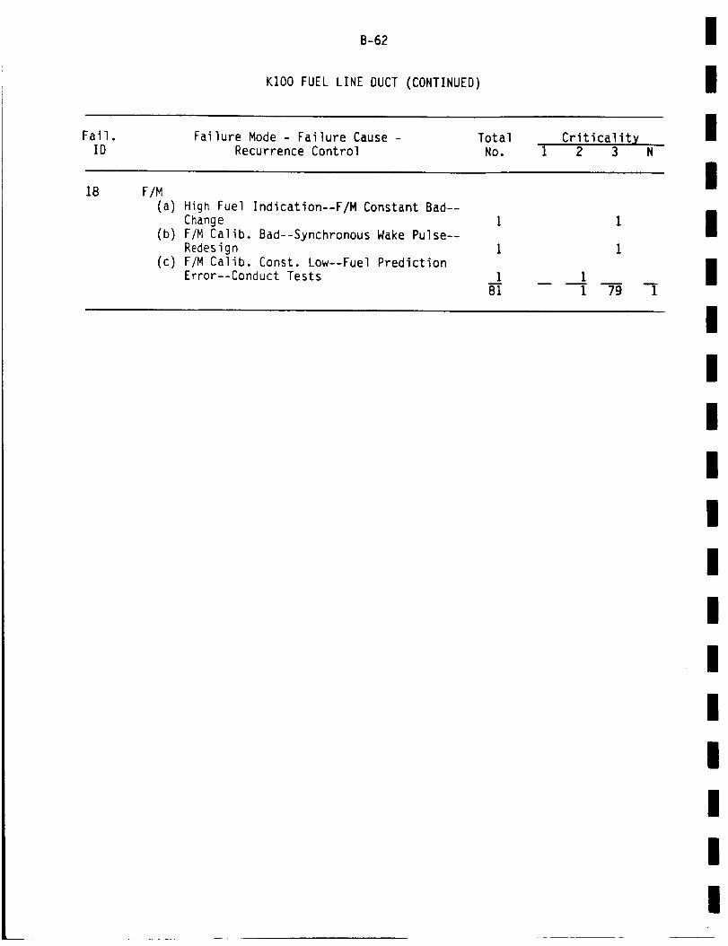
Fail.
B-62
KIO0 FUEL LINE DUCT (CONTINUED)
Failure Mode - Failure Cause - Total Criticality
I
II
ID
18 F/M
Recurrence Control No. I 2 3 N
I(a) High Fuel Indication--F/M Constant Bad--
Change
(b) F/M Calib. Bad--Synchronous Wake Pulse--
Redesign(c) F/M Calib. Const. Low--Fuel Prediction
Error--Conduct Tests
i
1
i81
I
1
11 79
m
1
III
II
I
II
I
III
III
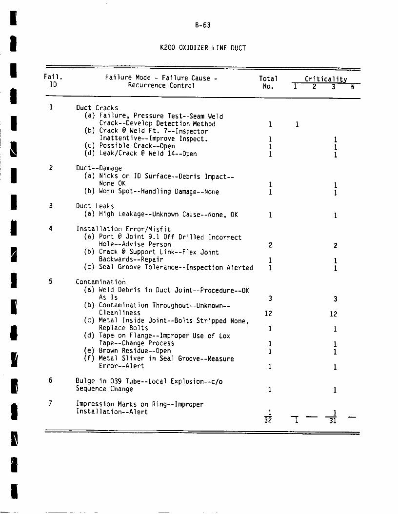
IIIII
'!!
B-63
K200 OXIDIZER LINE DUCT
Fail.ID
Failure Mode - Failure Cause -Recurrence Control
Total
No.Criticality
1 2 3 N
iiII
iI
|
|I|
2
Duct Cracks
(a) Failure, Pressure Test--Seam Weld
Crack--Develop Detection Method
(b) Crack @ Weld Ft. 7--InspectorInattentive--Improve Inspect.
(c) Possible Crack--Open
(d) Leak/Crack @ Weld 14--Open
Duct--Damage
(a) Nicks on ID Surface--Debris Impact--None OK
(b) Worn Spot--Handling Damage--None
Duct Leaks
(a) High Leakage--Unknown Cause--None, OK
Installation Error/Misfit(a) Port @ Joint 9.1 Off Drilled Incorrect
Hole--Advise Person
(b) Crack @ Support Link--Flex Joint
Backwards--Repair
(c) Seal Groove Tolerance--Inspection Alerted
Contamination(a) Weld Debris in Duct Joint--Procedure--OK
As Is
(b) Contamination Throughout--Unknown--Cleanliness
(c) Metal Inside Joint--Bolts Stripped None,Replace Bolts
(d) Tape. on Flange--Improper Use of LoxTape--Change Process
(e) Brown Residue--Open(f) Metal Sliver in Seal Groove--Measure
Error--Alert
3
12
1
iI
i
3
12
i
11
I
Bulge in 039 Tube--Local Explosion--c/o
Sequence Change
Impression Marks on Ring--ImproperInstallation--Alert 1 1
32 1 31
!
I

Fail.
B-64
K300 DRAIN LINE
Failure Mode - Failure Cause - Total Criticality
I
IID Recurrence Control No. 1 2 3 N
ILine Damage
(a) Damaged Drain Manifold--Repeated Removal
HPOT--Replace
(b) Gouges on Flange--Dropped in Assembly--No Further Action
Misalignment
(a) Drain Line to PCA Improper HandlingProcedures Clarified
(b) Misalign Joint--Unknown Cause--Inspect
Contamination @ Joint--Sample Too Small--None
1
1
I1
15
1
I
11
15
!
!
!
K400 HYDRAULIC LINE
/
|I
Fail.ID
Failure Mode - Failure Cause -Recurrence Control
Total
No.Criticality
1 2 3 N !Line Leak
(a) Leak @ Joint 1/16--Elastomer Damage--OK As Is
(b) Hydraulic Leak @ Joint H-l--Relax of
Torque--None, OK
Joint Misaligned--Exchange of Nozzle--None, OK
1
1
1
3
II
II|i
I
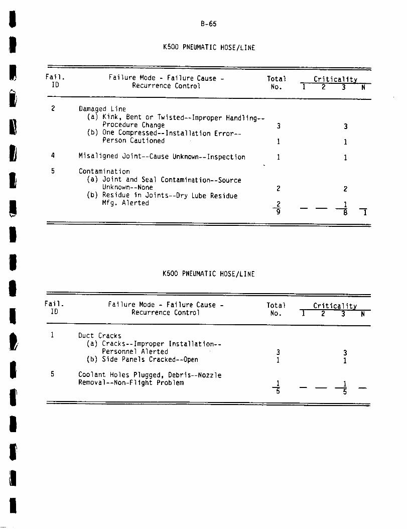
!!! Fail.
B-65
K500 PNEUMATIC HOSE/LINE
Failure Mode Failure Cause - TotalID Recurrence Control NO.
Criticality1 2 3
!
!
Damaged Line(a) Kink, Bent or Twisted--Improper Handling--
Procedure Change(b) One Compressed--Installation Error--
Person Cautioned
Misaligned Joint--Cause Unknown--Inspection
Contamination(a) Joint and Seal Contamination--Source
Unknown--None(b) Residue in Joints--Dry Lube Residue
Mfg. Alerted
2
29
3
1
1
2
18
n
1
I
it
K500 PNEUMATIC HOSE/LINE
IFail.
IDFailure Mode - Failure Cause -
Recurrence ControlTotal
No.Criticality
I 2 3 N
t,II
5
Duct Cracks
(a) Cracks--Improper Installation--Personnel Alerted
(b) Side Panels Cracked--Open
Coolant Holes Plugged, Debris--NozzleRemoval--Non-Flight Problem i
5
I
1!I
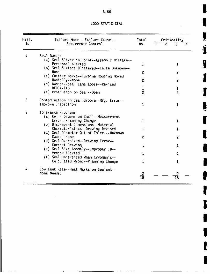
Fail.
B-66
LO00 STATIC SEAL
Failure Mode - Failure Cause - Total Criticality
!!!
ID Recurrence Control No. 1 2 3 N
4
Seal Damage(a) Seal Sliver in Joint--Assembly Mistake--
Personnel Alerted
(b) Seal Surface Blistered--Cause Unknown--None
(c) Chatter Marks--Turbine Housing MovedRadially--None
(d) Damage--Seal Came Loose--RevisedRF004-146
(e) Protrusion on Seal--Open
Contamination in Seal Groove--Mfg. Error--Improve Inspection
Tolerance Problems(a) Kel F Dimension Small--Measurement
Error--Planning Change(b) Discrepent Dimensions--Material
Characteristics--Drawing Revised(c) Seal Diameter Out of Toler.--Unknown
Cause--None
(d) Seal Oversized--Drawing Error--Correct Drawing
(e) Seal Size Anomaly--Improper ID--Vendor Alerted
(f) Seal Undersized When Cryogenic--Calculated Wrong--Planning Change
Low Leak Rate--Heat Marks on Sealant--None Needed 2
18
1
1
2
1
1
i
2
18
|I!
!I
It1tiII
I!
I

!
! Fail.
B-67
L200 STRETCH BOLTS
Failure Mode - Failure Cause o Total
IID Recurrence Control No.
Criticality1 2 3 N
Bolt Preload Error
I'IIgll
2
(a) Studs Not Stretched--Assembly Error--
Procedure Change(b) Damaged Bolts on Removal--Preload
Error--None
(c) Bolt Found Loose--Overload at
Installation--None
Bolt Damage
(a) Nicked--While Slotting HGM--Person
Alerted, Superficial
(b) Broken Bolt--Suspect Excessive Torque--NSTL Alerted
Stud Keys
(a) Piece of Key Missing--ImproperInstallation--Persons Alerted
(c) Keys Protrude--Improper Installation--Persons Alerted
1
17
1
1
7¸
Il|
L300 LEAKAGE--JOINT
!Fail.
IDFailure Mode - Failure Cause -
Recurrence ControlTotal
No.Criticality
1 2 3 N
.
Joint Leaks--Scratches, Unknown Cause--Alert 44
4
4
I!I
I

Fail.
B-68
MOO0 GIMBAL
Failure Mode - Failure Cause - Total Criticality
I
!!
ID Recurrence Control No. 1 2 3 N
Fretting & Galling
!(a) On Block and Body--Vibrations--None(b) Wear, Interference Condition--
Eliminate Interf.
Bushing Cracks--Low Ductility Material--New Purchasing 3
9
3
9
II
I
NIO0 INTERCONNECT HARDWARE!I
Fail.ID
Failure Mode - Failure Cause -Recurrence Control
TotalNo.
Criticalityi 2 3 N
Missing Locking Clip--Removed for Test--Reinstalled 3
3!
!
N200 THERMAL PROTECTIONi!
Fail.
IDFailure Mode - Failure Cause -
Recurrence ControlTotal
No.Criticality
1 2 3 N !Insulation Separation--Application Technique--None, Repair
Insulation Debond--Improper Cleaning--EliminateTools
4
15
4
1
5
!
!!
!

!
I Fail.
B-69
N400 POGO ACCUMULATOR
Failure Mode - Failure Cause - Total
!ID Recurrence Control NO.
Criticalityi 2 3 N
!
Cracks
(a) Cracks in Welds--No Failure--MRD091051,None
(b) Crack in Baffle--Gas Pure Defect--None,Inspect OK
(c) Cracks in Slotted Wall--Open
1
i13
1
113
!I
I N600 ORIFICES--ASl, LEE JET
Fail.ID
Failure Mode - Failure Cause -
Recurrence ControlTotal
NO.Criticality
1 2 3 N
!!
|_.
|
1
2
3
Orifice Deformed--Open
Tolerance Problems
(a) Orifice Not Per Print--Rework Wrong--Personnel Alerted
(b) Lee Jet Pin Not to Print--Installation--Alert
Low Torque Value--Installation Lee Jet Error-;Alert I
6
3
I6
)
|,I _'
!
!
B-70
(THIS PAGE INTENTIONALLY BLANK)
!
fIIt
I
IIIiii
t!
I
I/
|I
!1
I
APPENDIX C
UCR REVIEW
List of High Occurrence/Criticality Failure
Types by Component
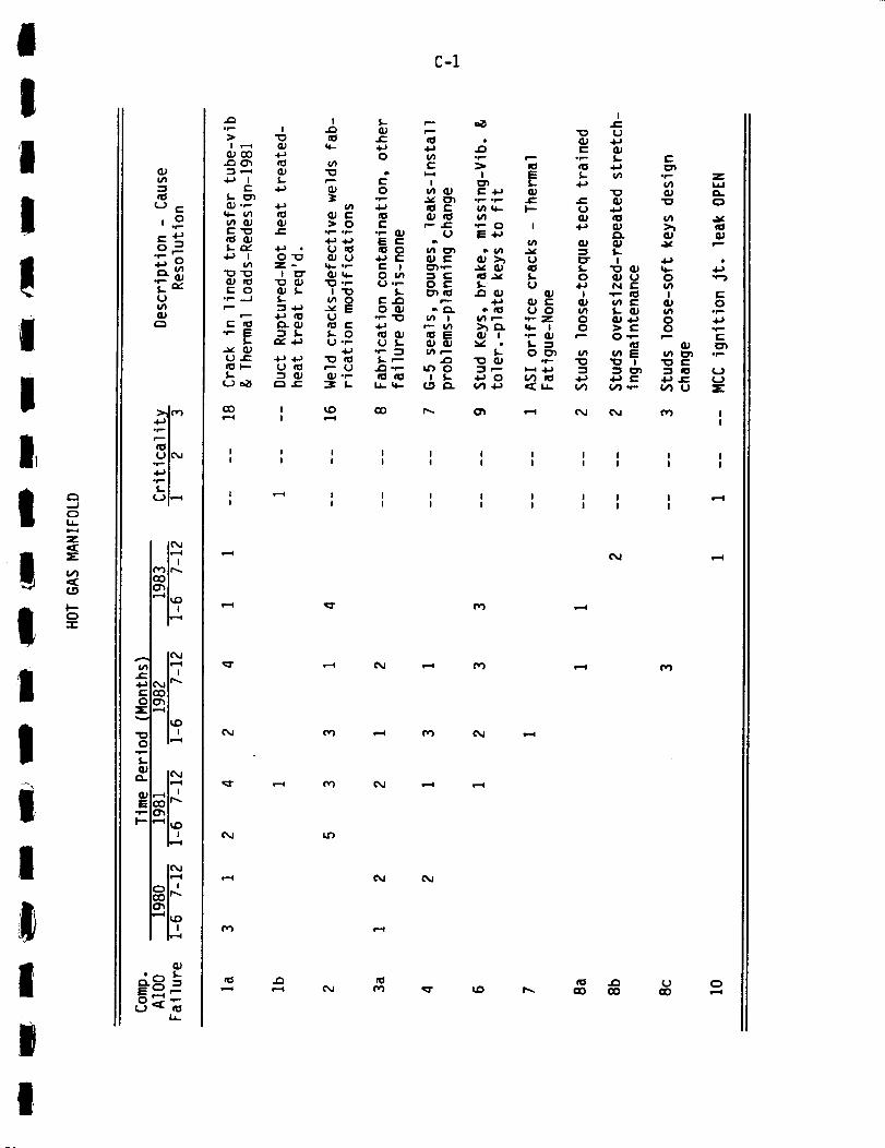
I
1I
!!t
!i!!!,I
I,
I
I
i
...Jou_a..-4
zc:[
(/I
0
(I)Ln
e:l
u
,.o
u(/I
ul_,J
,4.=,'1
I |
c_
| |
i !
•_1" c,,4 Ir_
0o_:E: ,--,
"" I',0
O iv-,,_.p=.
o. I_1
_I_E°_" _
_,r-.
or-.
u_
• I
I _ QJ
s- _n
I_'o r-
"o'o ! 13"
c" 0 ¢1 _.,- .-I !.-
•,-I= "IS..
_II-- t.)_0
CO,--4
I
ioq-
_n
> 0*e- *P.
u
cu_-
0VEu
I- 0(J °r-
,-" U
L
Cx_
_O
C-I
Ir-
I_ u 4_
I- o _;U 4-_ N
(1) I ",--
u o _ I-
I 0°,- _ ,-- 0f,. -!O I_ _ u_
I I I I I I I I II I I I I I I I I
E
•r- Z
>_
_ I r"e" _ O_J _,_ o_,,.
! "IO r-
•," (_1 U _"
!
I II I
i I I I I I I I !-,=1
I I I I I I I I
f_
un
c_
e--i
,=-I
¢M
I_ GO CO
e-i
i===_
¢vl
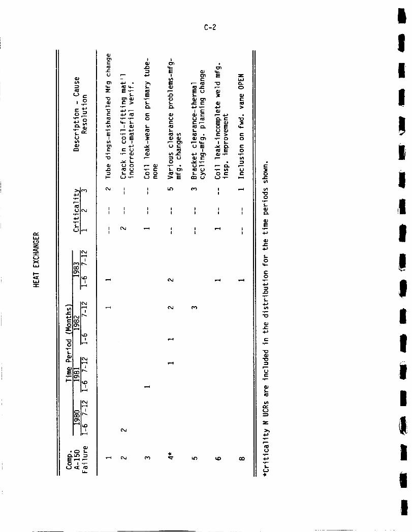
,,.,,,,I.i,i
z
x
I--
,.oC.I-_
_ ,r.Y.u
0.)
,4--'!
u I(",,,i
_,,J l,--.,m
'-'I_++,
c"_,,l_,...
oor_=El,--,
I',Dm I
+r-
P
Iml ""4 I_0i l
I !
i_. l.n .-sIE +--+ ,'"O t .,-
1.1_
C-2
O,J I I _ _ I ,r-.l
I I I
I I I I I I I
I I I I I I I
I L"k,J _ I l ,,,-.4 I
I I I I
,.....,i (',,,.i
,,,-,+ o,,,i 1'_
,..+ot-
O°_
f,,..,.
133E
°_
..l..tt+
0_e-
_..0
t--0
4.1
.f.,..
.p
O3r'-
t"
0_
"s
Ut'-
.p
oJ
u
z
>_.4-1
P
u.p
op
u41
|
II
I
!i
II
i!!I
II
I
IIIii

!t
IIaII
l--
IJ.J
z
z¢..-=1
,!
I
II
i
I!
!
u'l
r..o
o0p..
aJa.
QJE
,,oe-.O_0 "_
ll....P=_
X_
|_"4
co
iP,,,-I
I I
cO
| |
iv=-,i
• n
NP,,,4
!,-.4 I_
• C::} 5,,,,
O I or...
C-3
,--_ O0 ,.-0 ,=.q
i_ _ ,_I ,--.q I.=-I
o_
o
G)..C4-)
0
0
4-)
4-)tn
"0
"0
_.)
t_
ut
(..)
3[

"¢3aJ
¢-
4Jt--O{Jv
C)I--(.3i.tJ'-3z
zI--t
Z t/1.¢=4-)¢-c)
"1oo
o1--
GJeL.
GJE
Ol--
I--
(IJ¢/13i10(_3 E
_._
a.i
,.6--'1,_l
_m
fDI
UIC_J• P i
._,.a i
UIv--_
ICM
COO_
leM
C_jIr TM
ooo_v--I
| i
IC_J
o_•-41_ O
IcM
o_r-o_
iv,--_
oJ.of,.
_.C)
1,
C-4
zhi
C)I
(/1
U
f,.U
OJ
¢1P
4-)E
PP
_J
Of,.
f,.
E
cM
"1o¢u
¢1¢-u
o)
P- o
I
14- ¢/III=1
•Io _.¢:: 00 f,,-
¢I E
¢M
I I I @M I I I I I
I I I I I I I I
I I I I I I I I I
I I I I I I I I I
c_
t/If,.0J
op-
4J_J
_J4-) r"
(13_J'lOU @JII_ !-
..4
Ula-_J
"IO
U _
N,¢1(M
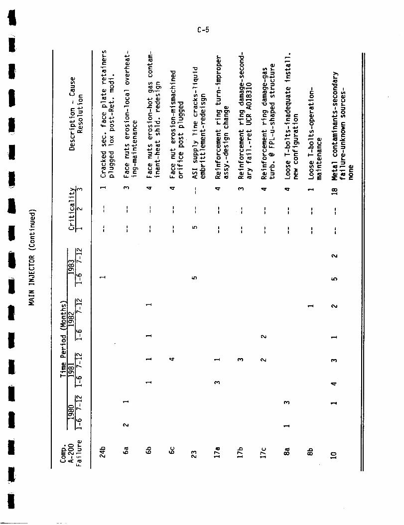
|I,
I1!I
UII
tiI!
!I
iIl!I
f-°p.
e-o
r_0
"3Z
Z
s-
C.J c-
j.o
u_QJ
.i--*n• _ m
_m
u #t',,,,i
.6..i n
_m
U I,'-"'a
Ic',,J11"--4
l I
oO
"_ I_,{:)! !
f. I i
L_,dIt'"
OO'13E,_
'_" ND
O u,--.a
op
S-GP
_. IC_
E,,r- 0"_
I,--.4
I-
¢)*_ _
_.c)E ¢_1 ,-0 I "P
u¢_ cou_
C-5
I I I I I I I I I I I
I I I I I I I I I I I
I I I I I,r) I I I I I II I I I I I I I I I
(M
141
,'_ ¢M
•-_ cv1 _r
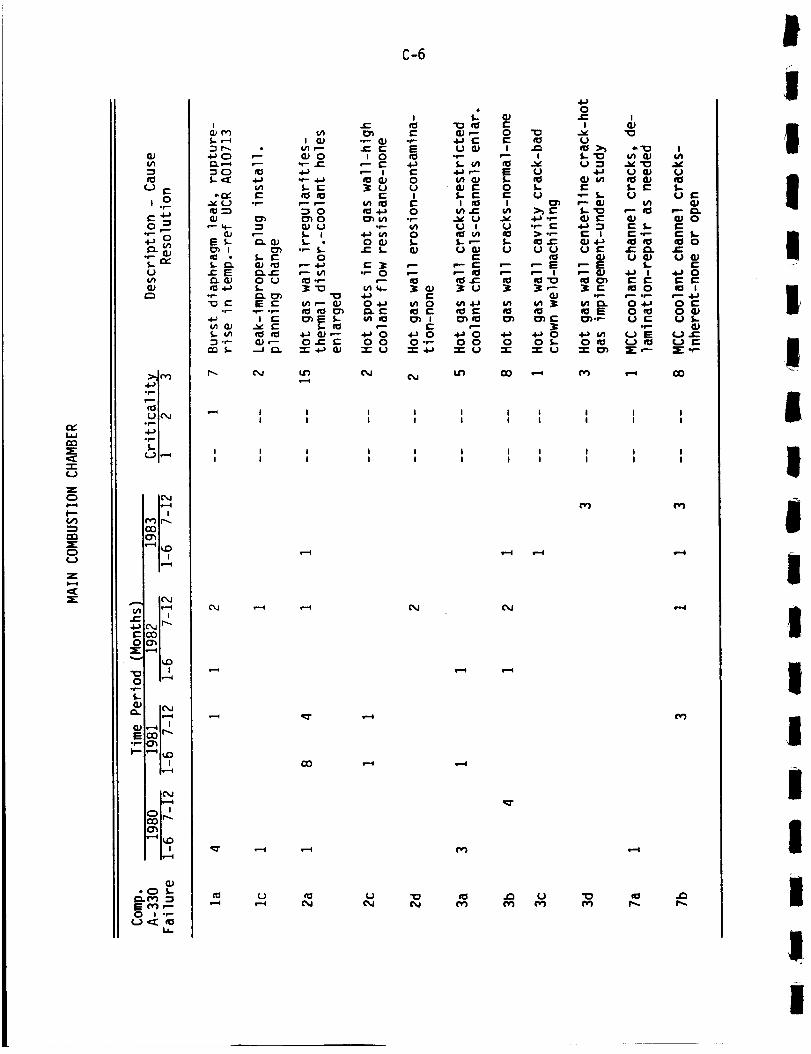
CZ:
122
_E
f.J
ZC)1-.it'-(,,'1
C)(J
Zi.-i
JE4-)
O
O.r-
O.
S.p-I--
f-4-_D "_
r- O
_.. Go:(J¢/1
b._m
m,rGIUle, J
_m_m
_ m,"-*
l(%JhJ-i| ,
'_IP_
i i
I_,Jh'--(I i
:10
=-I
! iiv-,,l
i_=i
i_,,i
i,_,4
iw-,,,,l
(U
#,.m-
i
_
_ OU
• __E EE
_._ _
P.. (M
C-6
Ir-
{4 _ EI eJ "P G} "P"
_"" -¢: E E(U 0 I 0
**-- -£: P- I::: 4-)4-.) _" I r'
S-I- _U U
"_ 0 ItS .l-J 00 _'J I,') .r-
S.- i 4-_ v_ 0S.- -- 0 _.) S..
S.- S.-• .£:0
_CS.-- _'- _1_
_P" _ 0-t-_ I_) 0
_ {U_- _-_ 0 _ 0O.C " 0 0 0",-
"r" .1._ qj "r 0 "r" .t_
I.r) O0 od
0*r-
.l-i P--
f,. l'-I I_
¢_ ..IE.._ U
I
S.. ,-"U W
r-,'-'- I=:
_I ¢"
vl .I-._
P4-_ 00 0
-r- U
0i-I
EI-0
II.'1
0
l-IJ
m
0-r-
01-- I
v O _ ._'_ .._U 4-1 U _ U
S.- E f,- E I.-U ".- f,- U (.J r"
•pC" 4.b "_i E _h- E•P E I IE-P E S-
II_ ..C _J .I-J _ ItS I_ 0
ICl _J U_J U_,--E ,--E S.. E,-- m ,-- W ._ , .*-) 0_"o _cl ol E E IE £:
(IJ ,r-. ,,--.I- r- .t.._
_E Oe_ OqJI_ I::: O_.,'- U I:: (J f,.
• .,-- Q)
O f,- 0 11=I _-) _ U _""I" O :2:: I_ =E,-- =E:: "P
I I I I I II I I I I I
I I I I I I II I I I I I I
I I I II I I I
I I I II I I I
CM
I-,.4
CM 1,'.,=1
I-,-I
!II
I!
I
mIIIIiIIi
Il
i
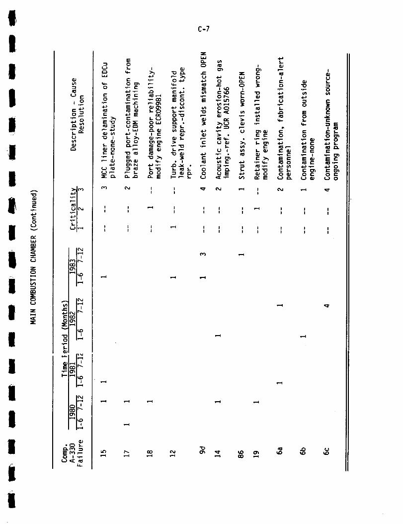
IIII!
,_.'
!
IIFI
I!II
IiII
ii
"o
.=-st-
,p-
t-O
Uv
iJ=i
-i-c=)
zC_1=.¢
I---¢11
z
,,n
u f..
i.-4-)o _
¢Jv1a.p
•d....,i
_m
_N
uIC%l
<l._u
I¢%1iliq
• i
("_-)Ir,_
,-'-Ol_iDI I
0 I *,-(-) _ e3
M C_
,-- >_
q-
e_ c-E o
U4-) 4_1
0"_
=C
!._ •
C-7
I _ CM _ I CM _I I
I I ! _ I I I
I I I I I I
I I I I I I I
I I I I I I I
('v-)
vii
i--,I e--I
l_l eiI

.--J
=E
(/1_E
I.i.1iJNNC3Z
QJ&/1
El
(-J c-
U1/II1)
C_
_,
U|_,I
i!--I| !
r',,')Ir-.-
,-.41_I I
O_
_'_ I_C_
0 m,,-,.,-qof.-
%...
(_IC',Jm_
QJ _ It...E
I I
I'r_l
leu
°m.-.
"_ F.O
C_• C) S..
O.qc_ "E o_ ,--O I "P
¢._ c_2 rOI.i..
u_ _r It')
I I
I I II _ m
v-4
c_
q_T
O_
u_
C-8
fvl ,-_ (M (M_r
I I I II I I I
I I I II I I I
,Q-
N
i--I
C_I N CM C_I C%1 CM C%1
lid _
I I I II I I I
I I I II I I I
UD 'Q"
CO
_r
cO
4(.tE ,-- -P_ lidC%1 (_1 CM _1"
OJe-{4
O,p-
f,.
QJE
q...
4-)
I-0
c-O
4a
X_
l-
e-
e-
Ue-
l-
Ul,Y(J
Z
If--
P
Uif-
4_
I
.I
I
II
'...:
,
Ii1I1III
i
1I
iI
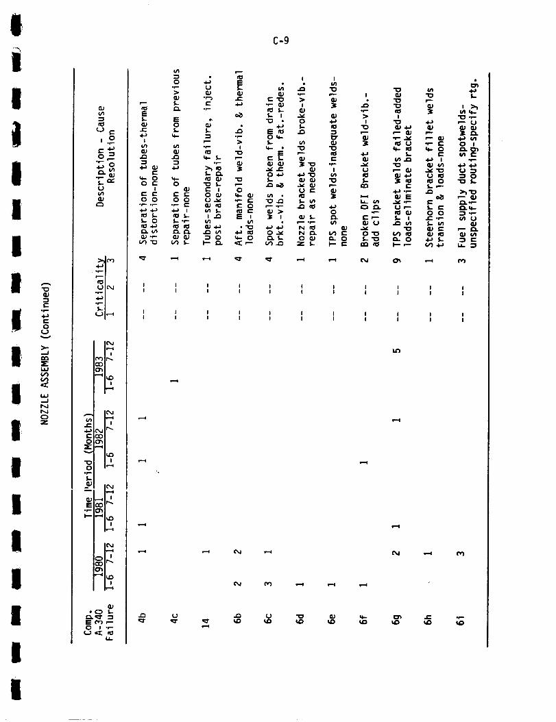
!|!|iIII
iI
!I
II
III
I
Q_
,f=.
0c..}v
_.INN
Z
Q.PU'l
,.o
_o
(,.)
Q.I
._=*i
L,)I_,J
Fml
,_ I_,,p-
-_I_olin C_I
! !ii--i
I,---4
N,_
(la• C_ f,.-
¢'_ ,,,_ ,-,,is= c',,") _0 I .r-
f,J ,mE _I.i_
I=f,,.(IJ
,.I::
Ii/I
r-
O r'-I
O O• p,,..f-
,,i-) .i-),I:I f,.,.I,.. O,el ,,l.aIzv)Q,) ._=-
v1 "I_
i I I Ii I I I
I=-4
I I I I
I I I I
•--, I'M
C-9
I.-'4
"_ Ill
I
QJ4.JQJ r-,.'
_ .1,-I::
I_.C_ .t_ I
_,t.a (=} Ill
,,,_ ,r-. e-
_ 0 0I,- I ._-_
&1,-
i/I i__
_-- IJ
4-_0 1_._
4,.i.1.1U
0
>_-_
U
i/1
I I I I I I I
I I I I I I I
I I I I I I I
I I I I I I I
.'.-,.I
.'.4
(M .,-i ('_
I'M _ .,--I s,-,,l i,-,.,,l
(,J "_ OJ _ I_ _' .,,-
i
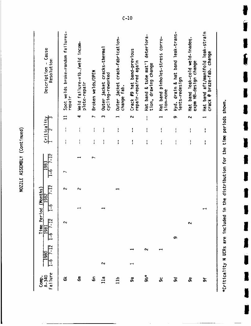
1-.lI
4-1t-O(J
>-
r_
hiVI
':E
I.IJ-JNNE)Z
VI
(-) (--
U(,'1
"Ill
L,) IO,J
,.l,.wi
L,_ I,,--"1
IO,JIi,-,-I
r,"_Ir-..o0cr_
! i
IO,J
IJ1 I_! !
e-._ CM If'_"C:QO00"_
.,_ I I
o- |_1
E
I-- ,--41_0
_i_z
Iv-,,,,l
.C) S-£_._- :3E n') ,--O I "--
i.
I
S-
E°P O
*r-
E
c
I z
P.,-_ *n_ -_ 4-) _,,00. ,'-_J 0
C-lO
c,,J
I I I
I I t
I I II I I
(M
I
_.. 00 _-
_- o
{u,.-. _.- {u ._
¢- I
.o 0
e" "I_ _ 0
._ '_ .._ I£:
4-_0 4=_0•P _I oP
"I" 4.._ '=r ul
I e-,lI
I
i-
$-
I
e-
"Io I
=;
¢-
_T
E
P.l=0 UUI E
I_1 *P
P
i_ "r"
E
X-I- G_
eM
.lI
I
m
•- UO
q-.,_ ,._
_ N
I I I I I I I I
I I I I I I I I
I I I I I I I I
I I I I I I I I
._ (J
¢M
¢)
e-4 e--i
0.l=I/I
0
l-{u
_uE
4-)
_Je=.
I.-0
0
I,-
.I,.=.
"Io
_J
e.-.IF.=.
"IOe3
"Io
£::
¢Il-
el
(=3
z:
r--
iClL>
I-¢_)
iiiItIIIi,I
II
II
II

I1_1 '_
!III
I
IIIII
I
III
l
"Io(IJ=3i.-.
.r-"
c-o
(=3
>-
wisl
=_irMPMc)z
QJ
:3
L) ¢...
,.o
s.. ,'_L.)
(u
,,dI.BU
_u
It::l I
(.,.)IO_J
Iv-,I
r_l_
,,g.) _,,,,iIr',-r-.{_ oC;) Or_
Z.,-0
I_.0
n n0 I,"-S
"l'-'
QJa.. IC',,.n
I,¢,--q
E°P" CPI
eJ• C) S-
C1.x:" :_E rfl ,-.0 I .,-
(..) (z: _1.1_
_u¢-.o
.p..
o
E
f--.
(1,)
I
(1,)
r...
i,
4-) aJ
• F-- O
o t--r-3 !
.kL.)
s- e_o,'-" (_
i r-,_" cu _"o _-. z o
• r- I hi .p.
"P O "_ ",'-
r" n_ (U .p- _. e-
LJ ¢_ O is, _.,-i QJ _ _vl
_ (/1 E'_
O 6/1 ._ _ I:::P {_ U E PeP
S- S- .P O# 0 "0Ul.P .IO I/1 ._: q-I=
_r_i-.-I
¢'M
I-"4
cO
C-ll
I II I
i I
I i
@d
14")
CO• -, (M
IlO
I (- I
-- E _"
E I=: ,-- .6-) ,--O "--- J:_ =i} IE "10_- -_- E o ,"
_J V'I i.l- I .4=
+: _- _ _._ ,I to 4-1 O QJ f,.."P _J P"P" I IE l/_ "IO Ou,l r- I_ "_ .P IE _J VIO0 _E _J 0 WW _"
0J I I_oJ I_ t/I "I_"I0 QJ IO=C: .,.- 4a oV'_ _J
_'_- _ ,_O E _._J
"_ O 4_ "P 4-_ IE 4-_ U W _"I/I I".p S 0./ { .I_
E E IO U I -P 4a !.. "I_ !.II_ S,- P E ,_ _i.. P U | E "f-
0 X _" _ 0 I- *,'-I_. (I#-,-- G3 (IJ
_" _1" o'1 ,--, (%1 ,--i
l I I I I I
I I I I I I
I I I I I II I I I I I
s--I
i,--I
o
c_j
i1_ Jo i10 e._
(%1 c_j (%1 ,-_ ,--i
OJ=i/I
i/1
O
I..
4.)
..I=
0
0
.la
1-.l.avl
_J
.6.)
I:::
_J
e-if=-
l-
i/I,,v.u
z
I

.r--
C0
,_JNN
Z
k.)
_m
_m
(.9IC%J
l(%,J
O0
"al,,D
IC'_,J
m,,.--,m
,,¢.)C%.imr'_"
CO000",
0 m,,--.¢
|_
IIJ
I-- ,'-4 i_ 0
i,P.,..4
.'oI_,D
my-..4
• 0 5-.
O I .r-
fO .0r_ I_
owl
C-12!I
i
I
m
II
I
II
I
II
IItI
i
i

I
II
iI
I
I
II
III
II
III
,.,,.-i.l.izo_
col.¢J
a.
.=.=il.l.I
1.4-
(..) ¢-
j.o
_3
_m*_ m_m
._m
_m
I¢%1
r,')iP_
i mI,i,,-,,¢
I,--'4
I i
"0 m i
,r'-
J,.
|_,,I
E _0 It"°P 0'_
I-- "_ I_D
1_"4
Iv,=,=(
*Of,-_.¢_ -._E '.D ,--0 I *P
IJ.
C-13
I I I I I I I I I ¢%J I
I I I I I I I I I I
| i I i i I I i I I I
i I I I I I I I I I l
,--, ,..-i cxj
,..4 (Y) C_J
s-=.¢ ,,-=¢ 14") ,,.=¢ ,l=-¢
s.--i ,-¢ od _iO ,=..¢
u (lJ *"1 u "o a: u ,1:1 u
"1o0
S-O
¢,-
.=0
*In
*r'*
S-
"10
J_
*r'-
"o
"Io
r,m
U
.ira
_VS-m
3[
U
i

A
r*r-
e"
O(J
p,.
c_
r_I.lJ
Q.
._JI.tJ
i.i_
vI
(J c-
o _I'm"
s. P"uv)
.*-,m•_ m
_m
•it,_ i
IC,,l
iv-....l
e--4.) fM m_'._
oo'_
0 m_,,._*r-
aJ
0JE _:o '_"
'_m_m,---a
I¢'_U
_,,_
,-_|_
i w,..,,,I
*C) S-
E _D ,'-0 I .r-
u ¢1:: iI_1,
I
(/1
SEE
%
*r-
_m
or- O
LE
0*r-
.r =.
s-
IEo0r..*
V1
os-q_
w--- Ie'_ ¢n
or m
(2_ S.-O..C_
o
o
Ico.p
o_m
_J
UU.-_
U..O
_J
P*m--
q.-
s-
"o_.-0o00_cOul(_
cor-,_,
(/I0,-/s-o
C-14
*P ,p .p
o_ O_
_ _ m
_*_ _ _
U_ UO E
I I I I I I I
I I I I I I I
I I I I I I
I I I I I I
q- ..¢:: *r- _:_U') 14") I.£') Lk') k_) _ O0
C_ Er" RS0 *_"__- tI
I- (IJ
0 u I-_- O.,-v _
_) 1 :3 s..E E _ I
•," 0 I_.'_
£: S.- U _Cl(2) _) oP 4-)
S- S.- _2. EGJ (2_ ,t,- *r,-
I[:: r-- VIIp Ip p IP
-_ _j h, E
_i_ _i I
I II I
I II I
(JcO 0"_
I I
I I
I II I
¢3 c_e--I _iI
O1"(/1
u_"oO
lid
£.G)
E
4a
Oq-
O*Ira
4-)
.O,f.-
t.
tn
(1)
4-)
.p.
"o
f,.-
ue-
Iu
ul
(J
4-)qI
r-'-
Iou
,.i I
4-)
(..)"l'
I
II
iI
III
II
Ii
I
II
III
I
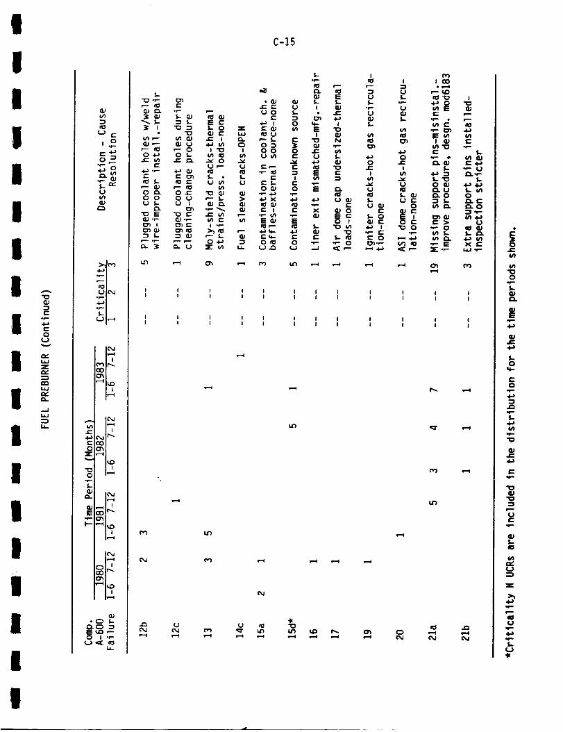
I
1l
IiI
I
o
z
a.
l.¢J
I
II
III
L.) c-
I=. 4-)
"P" 0
:_.M('vl
0 I,'--_
I(MIs=.=.(
c_
'-' I,,D• |
Is._l
I('M
¢-- . .4..) (_j ir_c_
Z ,---4
,,_ I n
°p
L
a_ |_J
E
_.- ,--4 i_O
i i
.p-
U_E _
C-15
¢=
0q..
i...0
4-)=1
f,.4..)In
.1=4=)
elm,
P
U¢:
.,tin.
_JI,-I0
U
:lE
P
U
I

°P-
C0
L.l=iZ
a..
..,=.I
l--0
Z
0°;,=.f_
S.r==I"
U
•,w..m
(.._ lO, J
o_,
; IC_,J
! i
! !
ir=-i| !
_11_
1_,,4
IC_,Ji,_-i
i i_,-I
I) I_,,,I
ic) '
(1)• C) S-
S= f,D ,--0 I "_
i.¢.
I v}
f"E !•i,D I_
•_'-" I v
lid I" U
V E _..
¢..) .,- rcS £..]_.,--
"_ ¢" II:1,'--0 ,'-- _.G_.r- cO (1)_._-) US.
(1_ .r- IG_ S- 4.-) (/1
r'- -I-) ('_ r,/1q-G,) "'-" G;q_.r" ,-- S,-rOGJ f--4-_
I II I
I II I
O
C-16
!
I
I
IIIlI
II
II
I
II
lII
I

,
C-17
I

a.c)nnn_
I--
-Jw
Ia-
I.¢Jn,-
v1¢11hi
"r(3
"I--¢n
.E4-)
O
Oo1_S--
a.
CUE
.p.I--
Q>¢n
(J ¢--
,.o
(J
.b-,u
(..) ICM
,4,--"n
_mr.._ m,,--_
I(_,jle.=,l
m l
,rv")ir...O0
,--'al_ 0
Is,_l
I ('_,.I
i i
C%11f'.,,,.
I'.0! i
1_'-'4
I C'_,JIs'_4
I s"_i
IC"_Is,_4
I,,"-4
GJ
E c'_J F--C) ! -"
(..) n_ II:1L.I.
C-18
CM I I I II I I I
¢M
¢M
I I I I I II I I I i I
CM ._ CM
n')
l-=(
•Z3 U ._ U G}•"_ ,--_ ¢%1 ¢M (%1
(%1 (','1 _ I_ I'_
I I I I II I I I I
I I I I II I I I I
•--I e--(
(%1
(%,1 _l sil
I'--I
CM ¢",4
e-¢ .--¢ It') ¢%1
¢%1 ("1 f_ _l" '_"
O
U1
C/I
O.p,-
I-
EIr..
QJJ_
I-0
0'I'-"
,.f-,
l,-
,,f=-
"I0
QJ
e-
"I0G_
U
GJI-
el
Z
It==.
I,-
I
Ii
1IIII
II
II
III
III
I
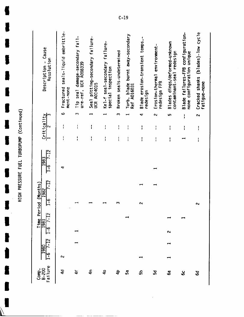
!
lI
!II
I!
Il
lII
!
Iil
ii
A
q.}:pe-.
t-o
-.,j
i--
_.J
L*
.,,,..j
L_JQ_
"I":
"Jr"
(_
fCS
! I
.&.j .v
(..)Ul
:>,Jr,')
• _ m
_m
• _.
.l,..a !
_ | v.....l
! !
m-1ii_
i i
ii, ml
_ Iv--(
jr. I i
OOhX_-4
_ i_,*r-
#(L)
* (_ S.-£_. ¢:_ --_E ¢_J '-"0 I *_
(.._ CG fOI._
!
r---
.4-)or-
r_E
-g.r-
"7
"o
%.-
u
I--h
c-O¢-i
c-
E
i i
•_ S.=
bocm
II#n_ CinoO 0i C) u
¢1 IE r_ o_itl ¢_) _l.n
4--_c)r-- • .I.-_ 'q"
I _'--
-- %- _,) (.._F-- "-s (,_--_
C-19
I_J
*_
E
b
o o_u I
I v)_- e- ¢1_l -r-- ¢1
(11 _--m e"
I 0 .._"-- q_ 0
_ en
b !
0 Eu
ul
0
_c_ o
C_ .r-
i---r_ _ 1-
I
Et-OS-
=l.--
ri
¢I:1ES.. nr_
.c:u.
I c-
O • r'-
• r- M'I
0"_
• ,J S-
I I I I I I I I
I I I I I I I I
I I I I I I I II I I I I I I I
i---I
,--¢
ii:1l,n
eII
.Q
1"4
i.n
i
i i ii i i
e,-i
I--i
Iii
I _ II I
,iI
U "oIZ)

A
c-
t-o
¢.)
c)n_n,.
I--
_.J1.1.1
1.1_
n,-
IJ.I
c_
=1"
¢/1
,=.O
O*e-
_u
S
I--
Q.}vl
¢..) ¢-
,.o¢-. 4._o -I
i==.
s.. n_tJ
¢Jc_
,.ib-, m• _ n
L..)I("_J
.4--,I
_J
r_,.,P|_r-,-4
tY'Hr..,.
i
I I
! i
Ir.-I
I_,.1
"'_ IS,Dn n
I_...I
i m
*C_ L_.C_EC_,--0 I .r-
I.a-
0
E _,_ 0
"_ O _J I
v_ _ 0,-
o L,-- I,-- _ ¢'- v'l
•,- E U
I o I_ !-
•,-- o_ 1_2."_ 4._
¢+- ,--_ ¢_l- E
_n_ LE QJ,.-- (_) _J Qj ¢.-
,-4 CO
I I I
I I I
pM
i+_tZ)
I I I
I I I
.--4
s--I
•w ,I_
Iil
•_ fO -,--
U
r" _ U• e-- "1_
e- (..) .i-)
o,- u._ i:: __._o i o
• r- _ 4,1 .,-s- _1_ Qj r-¢1 f,- ,- o> (..3 ¢I) E
I I
I I
I I
I I
e.=.q
C-20
I I I I I I
I I I I I I
I I I I I I
I I I I I I
Gh
Gh
(._ "_ I+- "1
•-', _ ,-4
e.=4 e--i
•-_ c_J ¢_1
.W
s=.=l e--I _ !"='1
OJ_vl
O
S-
E
_J
S-O
0
s-
(/1
"o
_J
"IO_J
r.--
o
_JS.-icl
v_
o::3
z
.f-
i=m
*r.-
S..(._
I
II
i
I
II
I
II
III
IIIII
I

I
I
I
III
I..-Ii-
ll "-4.a
' 0ov
C)
,...,
I-.-
..Ii.¢J
IJ_
II.i.I
-I-
N=..¢
I =
I
l
III
(=.) r-
,.o
,i=. f='="
_o
:>.Jn'_
uIC_J
U I_
ICMit-.4
i i
(_lr_cOO'_
| iis--_
.._. IcMIll 1_--4
JE I I
c_j If'-t-(Z)0o_
X:,-_
I_)
i:) t_.-i.r-,,
f,..,
_. ICM11....-_
• P (_l
I-- ,-41_ D
I1_..I
IcM
E @,J ,'-O I .P
Urn I_i.l-
C-21
I I I I I I I I I I I I
I I I I I I I I I I I I
I I I I I I I t I I I II I I I I I I I I I I I
_r
s--I
Ix1
4( 4{ .k
cM (M c_l N _"s--I ,--.4 i._ !'==1
If) ,--4i--I
-k
i_l I--I s_l s-.-I 1--4 s-.-I
O
5-
E4.l
J_
I-o
c-O
*p
i-
i#1
_J
"1o
ue-
l-
u
z
4-)
io
el==,
¢...)
I

A
"C3QJ
r-O
5"
a.O
r,"
l'-
--.ii.¢J
IJ-
W
a..
"s-(.9
..f-
VI
r-
¢-o
o.fi.
%=cu
a.
IE
(..3 r-
,.o
L.)(/I
GJ
o_ m
ul_,l
4--'1e_ m
I,_=I
"q I_0| |
C, jI r_
i r..,..I
i,_.,I
_,r-.o_
h=--I
|1,.-...¢
Iv......l
• C) L_._ =3E c_J ,--O ! ",-
I.¢-
C-22
I I I ! I I I I _ I I I
I I I I I I I I I I I
I i i I I I I I I I I I
I I I I I I I I I I I I
C_J s.--i _ s--4
¢'_ @d
Nc_l c_J
O
ul
O
1,-_J
_JS
_J
I,.0
q.-
0
4-)
l-
v)
"o
Cuf-
4-)
"o
"o
!-
ul
(,3
I..(.3
!
II
IIIIII
I
II
III
II
I
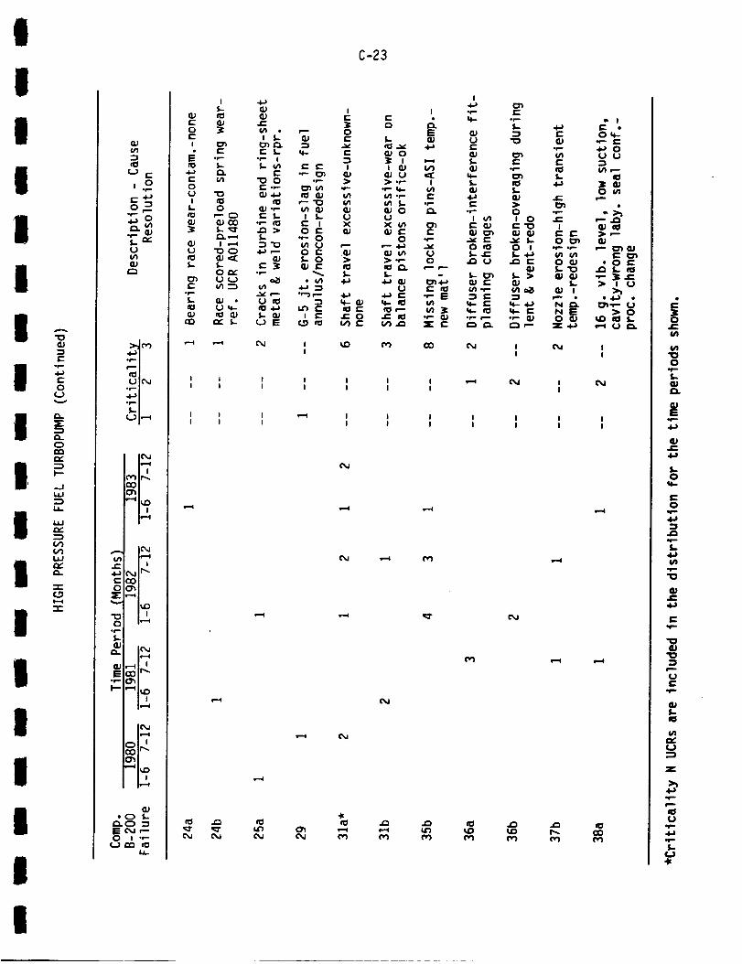
I
t
II
I
I
c)
I °i--.J
I"'
-r-f.Do,--e
I =
I
Ii
I
I
u (..
j.o
or,-
o
c.) I,--_
(',_ Ir.-.o{3
le---I
,... le, J
L" m m{,_.jir-..
e-co0(_
_-,._
"" I_O
0 m,'-_
.f-,
I.0_
Q. IO,J
S,t-"
G.)• C_ L
C-23
_J
iG)
.1_
S-O
e"0
It'-
4,a
q.,.
I..
e.I,.c,.i.a
e-
U
I

4-)f--O
U
=E
O-
CO,Y
F--
.-JI,I
1.1-
Ia.J
V1V1I,irv"Q-
"l-
-r"
UlJ=:
O=E
Oo1--S-
a.
E•iiI--
Ia5"-s
$.. Pr"(JfJ1
_m
_m_m(.,)l(',J,_m
•i-,,|
U I"-_
IC',J
i it'Y')It-..COO_
"'_ I_| i1_,,4
11"4l i
! !ir,=l
i_,=,1
IC_JI_,,,I
IF,,,,,4
a.I
,p-
I II I
I (MI
C)
@,J
.J_
C-24
CO _r_
Z C c-I.lJ I IO
C::) _ S.. OC O I
_n r- O- OO I ::l .t-O _. u_
P E
O. r- .-P _- .r.- •0 l.,.l _ _
•P _ %..
0 _ _ _ O,_ ._"(/) I_ 4-) "P P'- II}
•,-" "I ES O *" (_
,--_ (_0 _ II
I I I I s-,,4m I I I
I I I I II I I I I
"WU _ I_ U U
Zi,i
*" C)
E "T2
f,- P.l.a j=vl
E _r_
o S"-_ I0
I ¢/1 "_4-_J_ IS.-.P S-O EiE_..P O._-P" E
{/)
E:,-- e'-
S.- tO ul,_ .I-) ul_.) (4 .,-
I II I
I II I
{'M ,--I
GOe-¢n
(/)
O.i-S-
A)E
.p-4-}
,L0
,..-0lid
--Ie"
orb
U
I"
'rV"
m,
I""
"k
I
i
I
IIII
I
II
II
I
IIiI
II
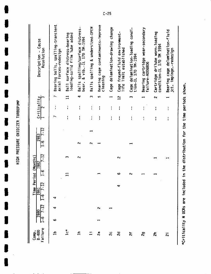
I
II
1II
II
I
iIII
II
II
I
CLC_
C_
In
La.JNI--4
I, iI
XC_
I.¢J,.v'
C_
i.¢Jrv.a..
"r-'_DI,,--¢
8_or,- r'I
4-_ C)
,.-.,
.,(l_m
_w
_m
3L
| J
I I
I-- I m
C_
0 m,.-_
h--,¢
Sof-"
I,--"¢ l_I{)
I"
GJ• CD S..
ol--"
i,a-
C-25
I I I I I I I I I I I
I I I I I I I I I I I
I ! I I I I I I I I
I I I I I I I I I I
¢" .r-- _ ¢.} "l_ _ I_ J_ .r-'--' ,--' Owl Owl C'_ _ _ C_ C_
I
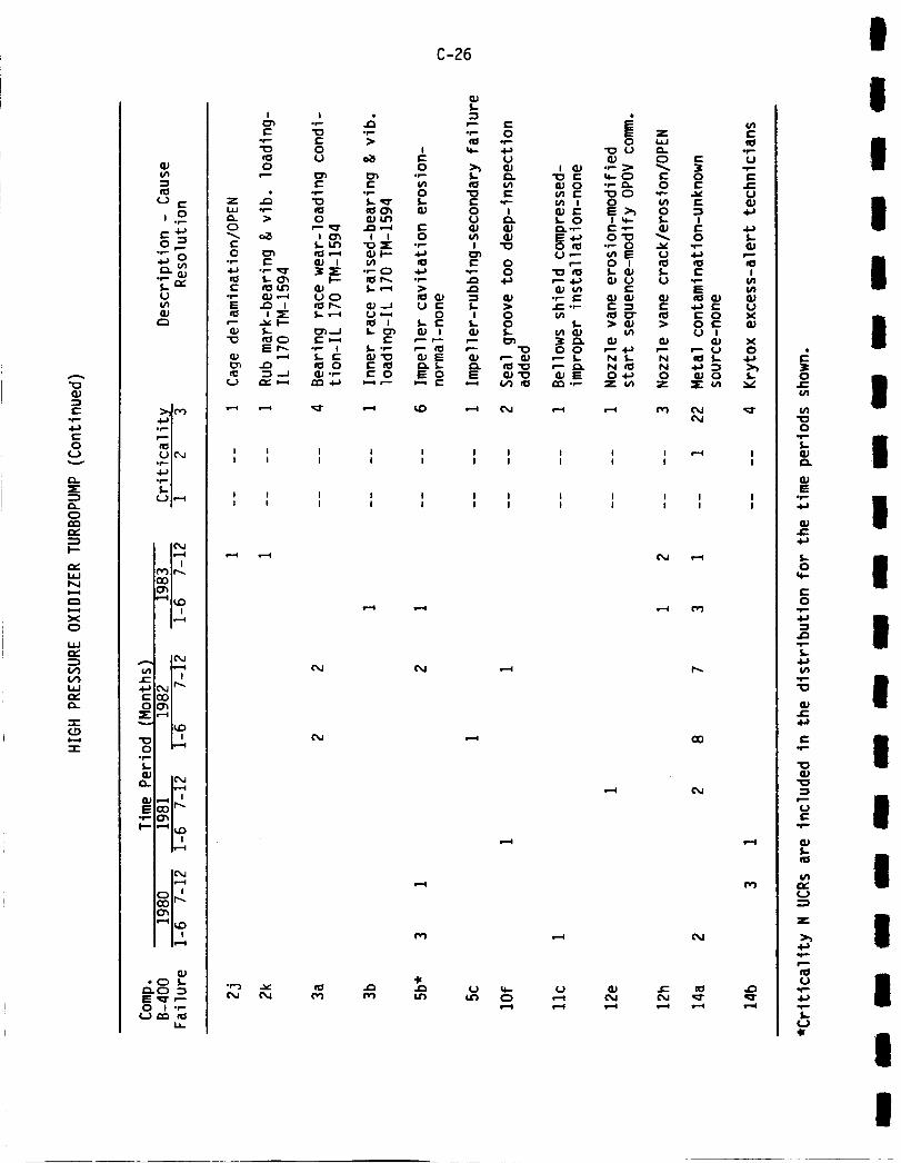
A
"1oQJ
0r.-
0¢.J
Q_
O
I--,
I.i.IN
i,'-,i
xC)
L,I.I
r,.
-r-CO
VI
l,,-
c-o
I::
o.If-'
l,.,O,l
O.
OJE
0,}
-I
i. oI::U(/I
..-,,
>.ll (','),.4l,.il• _ i
{'O1
(,.)I(",,,Jo_ i
,.dlll I
le,,JIf--I
re) it,,,.o0O"i"-q I_£:)
i !
l,r-',.-4
I !
L,,_jIr',,.ODO'I
I,'-4
I('_I,I"-,4
o'i
II,_I
I('_,IIv--"4
Ir--4
0J
_.C) :3
O I .r.-¢..) ,-n _i
Io')
ioo
r---
1.4=I -f-
c)
¢-o o')
• r"" _r
r- n_l l.n
I.-•'_ n:IC)
Er-,.oJ
I I
I I
I I
t I
Io_
0
i-o_
0
m ch
uo_r,_
or-- |
oOJ °_--
C-26
I I I I I
I I I I I
I I I I I
I I I I I
w-..I
.13
Iv)
"W-_ C.J
0
lJ
C• I -
l
_J
00
oos-
"o
z
I I I
I I |
I I II I I
e_
e.-i
o e.-
--_ U
I4-1
0 _-•f- G,_4-_ _--"Itl II:1
I•,-- I/1E WII:1 QJ QJ
O XO _ QJU I
_J X,--" U O
¢%1
!
I
I
I
I
0
- IE
- I0
c-O
mS,-
° I
Iu
° I
° !_J
- !
I
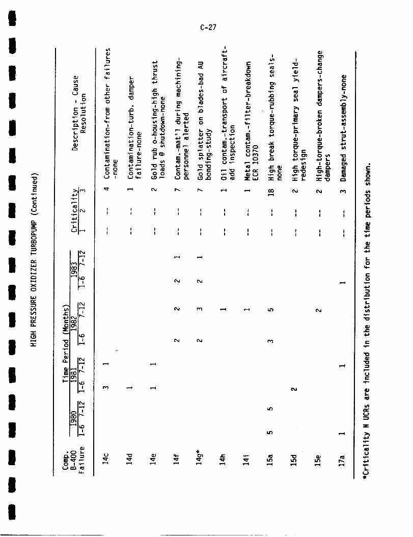
I
IIII
i
c
I °u=E:
I _c)
1.11'.,,,4
I xC)
hi
I..IJ,.,,.-
I-
II
II
I
("3 E
8_°r--
-{_,
>,,1_•d..._,n
• _ m_m
(..91("_,_
IC_,,JIf,.-1
IC,,lIs--=4
x i4._ C'_JIP'"e-DOO_
Z,-'_
,._ I n
*r-
l-
Q. le_.l
_1_E
i_=.i
i_=1
| •
{p• C_ S-
D.C) -iE ,_r ,---0 I .e-
i.¢.
C-27
! I I I I I I I I I I
I I I I I I I I I I I
I I I I I I I I I I I
I I I I I I I I I I I
s--I PM
¢M ¢M
CM CM ¢_
{M
14")
IJL'b i==.I
4_
,"-I _ 1.-4 _--I _ e'.=l !_1 I--I l_l s"l
E
14
O
L_P
4a
4-J
S-O
0*fro
S-
t4-1r--
4)
4-;
e"*r-
"0
"1o
0
*F"*
g_S..fo
z
P
u
I
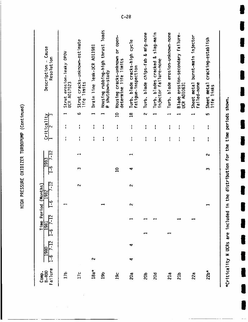
"13
(--o1--
e-o
(J
:E
r_C_rr_p,-
l'-
la.IN1,,-4
xCD
i,ies,.-_
laJ
-r-(.9
(/%
t-O
0op
E
&/%
i.o
o "_
uu%
•.l.m'mD_ m
_m
_N(.Jl(_,J
'4--'I
_m
L.JN,-_
r,-)ir_
(3"_'
ICXJ
I I
_,j |r'_
i i
_m_z
i I
I_,,I
,_
IE _" _'-0 i -,-
(...) e,._ _
_>C_
Q
ro
r_
I
c-O
o_'
_IndOU_
O
-'I_._,"
e_I"-,
I I I
I I I
I I I
I I I
{M
-k
r,,, CO C_
C-28
I
0 u
_- uo
e-
_._ ="
CoP -_ 0
U'P e_
U G_ _.PE P I
E t:
:3.l_ 5..i_
0
I II I
I I
I I
E) _3"
{'M
_r
_r
(j i_
N
I I I I I I
I I I I I I
I I I I I I
I I I I I I
(M
.1(
O O ,--_ ,--i {%1 e_lN N N CM N _1
O.1=(/t
I/I
O
f,.
i=
(uz-4-;
%-0
t4.
t-O
!-4-)
lib
e-
_J
f....
Ue-
_J
e_
f..)
P
u
.It
I
i
I
I
II
I
III
I
I
IIII
I

I
i
I
Ii
II
l
IIlI
I
l
I
II
l
r-*p
0UV
D..C)n_n,*
ILlNl=..=l
X0
l.iJ,Y
¢..0
¢-) c-
,.o
_o
iJl/l(lJ
•t-,.n
_m
UIC, J•_ i
.*-*m•_ m
IC_,J
m m
(') Ir.._
| m
mP,-u¢m i i
C'_..imr'_
OCh_-,--,
"" I_1::)
,._ n n
.p-S--
Iv"-I
S' _oIr-.-
i_.=1
,'--4 i_0
iv.,,_
QJ.C}S-
_-C)E 'q" ,--0 I .r-
C._ ,'_ _L_.
C-29
_O¢%1
I I I II I I I
I I lid I .--II I I
I I I II I I I
I I I i-,I II I I I
s-=l
¢',,Iq-f_
I II I
f_
I

A
(lJ
C--olm
C-O
¢.Jv
0.=E
Onnn,-
I--
n_IJ=l
_nl
X
m.mr_
U'%
-e"
OJ
¢J ¢.-
,.o
_o
ul
,,4,.m!
_m
U IC",J
,,f.l,m
_ m','--_
IC'_,j
!'7,O0O"L
,,,-,
.,-. I_i i
{xj It'"_0(:)O_
=E: ,,'--*
n iO u_-..._
.p.-
I--" "_ I_1_
1_,,,4
ir=...l
,,C) S-
O I ,,-'
C-30
I I I ,_I I 1
I I I II I I I
r_
¢M
_o .._ U ._O0 CO O0 C)
I I II I I
I I OI I I
(_) _ _
I I I II I I I
I I I II I I I
CO e-4 _-g
U tO .1_
_ _r
0
101
"00
_U_e-
I-0
q-
0Mp_
I-
"0
e"
"0
"0
PUa,
*p
I-
a_¢.J
Z
>_
P
U.p
S..
I
i
I
IIII
I
III
I
I
IIIl
II
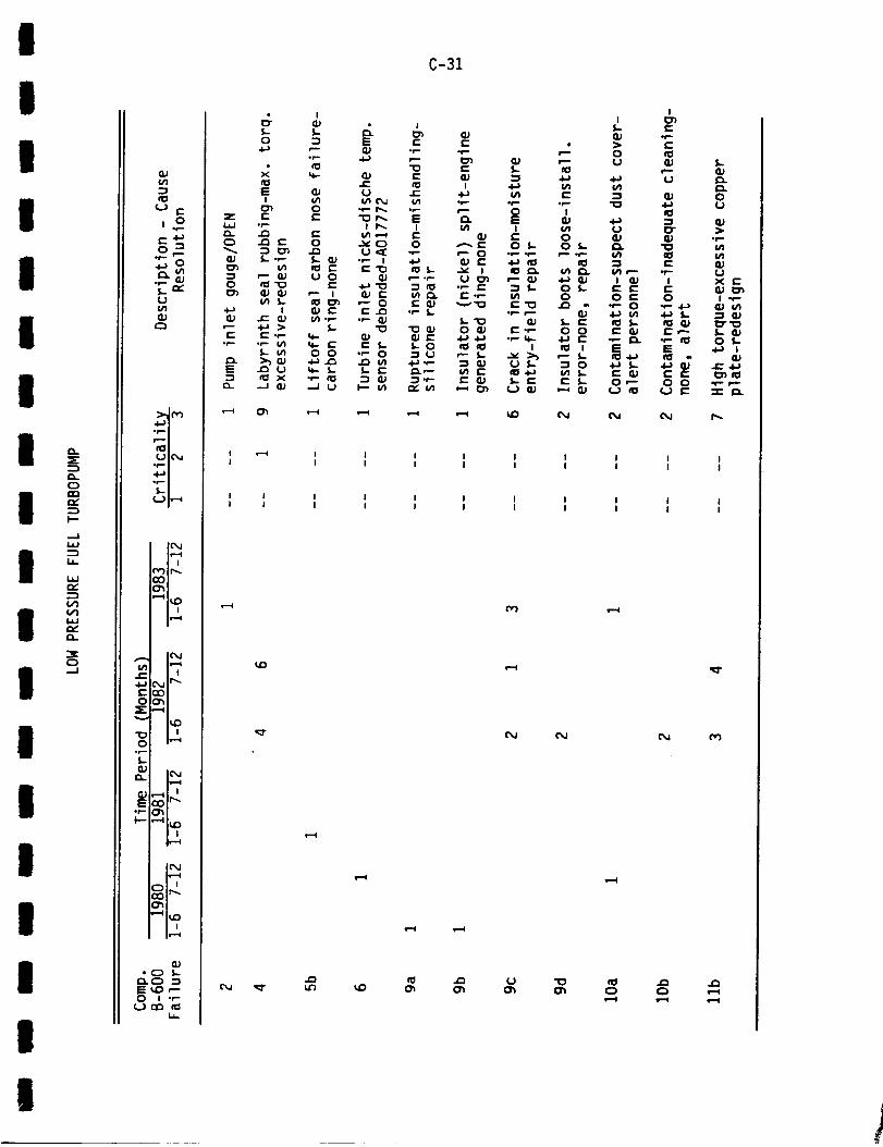
l
I
l
I
I
I
I
I
I
I
I
I
I
I
I
I
I
I
C)nnn_
I"
....Ii.l.l
I.I.
n,,"
¢I)
n,"a.
--J
(]U
Cl
¢'-')
,.o
l._ n,"U
.i...wi
ncllUIC'_
._ |.6.=.x
_..._i_,,-_
l@,JIt=--II I
rV')ir_O0
,-.41_ 0| i
I" I I4--_C_I II'_E{:_)
Z'--"
"--" 1'4:)
I IO l_'--I
£,.QJa.. IN
ri I I{301p..E
_-C)E_"-0 I .,-
0 "'_ _
S-O
EI
Z I::l,a=J or-.
0 _ ¢-
O _'_
os=- oP.- i_lL cn
-I _ Xn ..j _
!
I II I
C-31
If,.
• 0_'_ _ ,-- (..)
S.-Q.} .=,i _ 4._
I _ G,I i_4-_ ¢_ _ "=I•i=.. .r == op
!
0.l ¢" O ¢}_"¢- Of,- 05- I_.II (_ o_. osi lid of=" IG_
•=_ I _ I_. Vl _. I_P"U O_ ,'-- QJ .i-) _J I _J
• P = =l S- O f,- E e"t'- .,.- _ O O C
•P"-- QJ .l_ Ill
O _ IE.P O O " 0.1•i=_ 4._ .,-q- 4=_ _ ",-- I_.I0 I0 I I_I I I_
_-" I,.. ,=_ _._ r--, ,L I_I .I-)_ _J U f,- :3 0 4._ I--
E GJ t- I::: c- f._ Or--"
I
r-
,-.
cu o4-_ u
QJ
'- cu•P- cj
i x _"
o i -=-
•,-- i_ o I..E 4-_ i
•l=} 13_ J=4_IE _-" i_ecl
(j r- "_- 1_.
I I I I I I I I II I I I I I I I I
I 1 I I I I I I II I I I I I I I I
M
_O
e-i
s,.=l_4
_ 0', _ C) C)
I

"13CLJ
f-er-4-)t-0
CJ
0.:E
C1.
rr_
f'-
..JLi.I
1.1-
i,i
(,,'1V1i,i
:3=0...J
(/1
0 r"
0 _
"P" 0
(J(/I(1)
:_1 ¢")
nDIUIC_
IC_It-4
h--_
IC_
t"CM tr_
O_X_-4
O 1_....4°_,,.
I-
Ir.....l
Q,)E _1_ It"
°P" O'_
11'='=4
IC,.I11"'=4
(1)• _ _.
E _,D t-O I ._"
{...) n'_ _0I.I.
S.. II .r- 0"_
C_ _ -r-_0 _,) _--E S.- U
>_
0 ,lZ _- -P _0
Q ¢0 S.- -,-" _)I ,-- C_._ JE
¢'_ I _. 4-)v GJ I
cr S.- S- U f,- .._
0 C_._ f_ _, _1
0 (1.) t-(_ U &- OJ 0 "0> I .I-) E a_
P (1_ q-ul ",-" 0 _.C_
t/I IE: .P I_ p
X Or" E_ :3
I II I
I II I
L)tM
I II I
I II I
r,-)
C-32
I
Q_
O_ Z e-U_ _ 0X £- I_. I=_) 0 C) I
0 5-- 0 I:::
:3 U =3 _.)¢n 0 ¢4I/1 P-- u__)._ _) 4-)f.- l,- 0
I
_ e- -1,- _j
I I I _ I I II I I I I I
I I I I I I Ii I I I I I I
r,_ cO (_ C3
c%i
P, o_l_ _ NCM C%1 N
I
I
I
I
I
I
I
I
I
II
I
III
III

I
I
II
ll
I
G_
N
I °b..4XC_
L_
g _LLJ_Y
n _
I
II
II
II
._ O
C2
(,,) I,-_
O_
"41_C)a i
.j_ n ._lr_
OO__-- ._,_
""' I_JD
0 i,,,,-,ior.-
L
Ir',J_i iw'--4
QJE, _0 It",,,,.
Iv,,,,,¢
_,r-.
i i
Iv-,,4
JO._ "-',nE CO ,"C:) ! .f-
C-33
: : : : : : : : : :
'L_
(%1
E
e-
l-o
_.
c-o
!-
ul
oJ
ue-,
,.w,
.I
U
_m
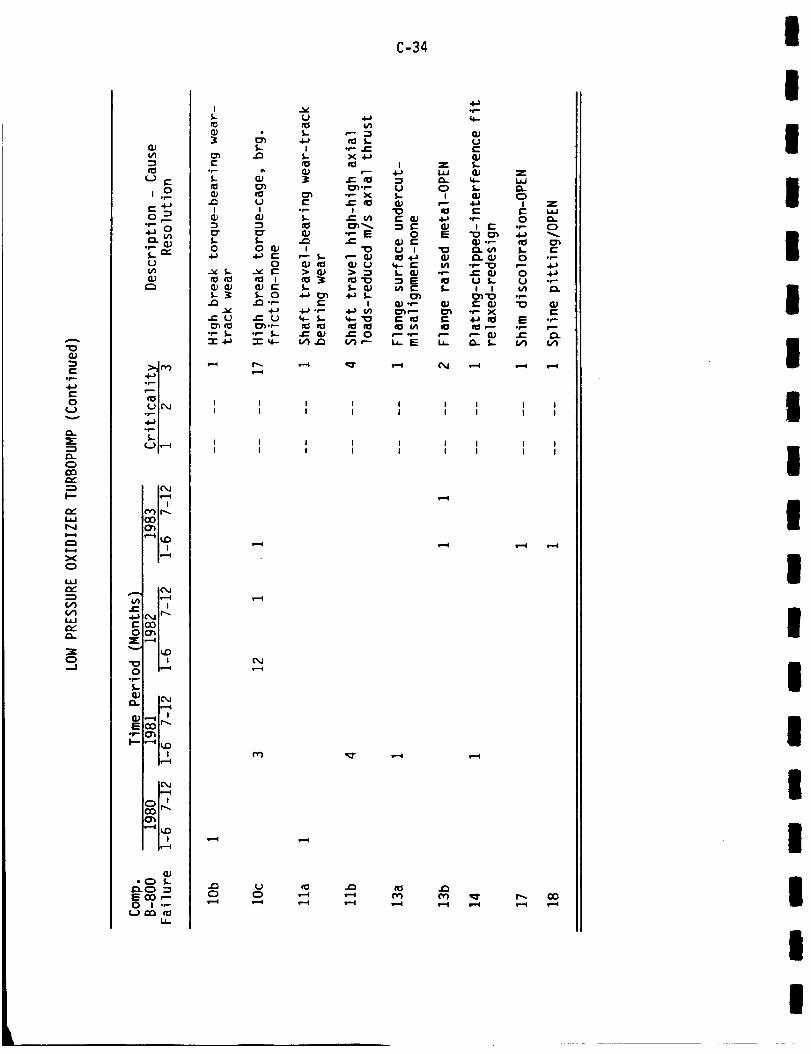
°r-
r-O
(Jv
=E
C)
OC:
I'-
Njil
XO
i.i
VI
I.IJ
C)
Q_
I0
('J c"
r._-)O _
(.3¢4
•0..,m
0 lC',,J
ww-.u
_t
I@,.I
_h
'm"OI_Z3
I('M
IV'--q
_ C'_.lIr'"
E_00_
X:,-_
.p-
Q)
1_-,4
E _lr_
"P" 0'_
F- "_ I_D
|v-....I
• C) S,,.r,,_ECO_0 I ._
1.6.
l
£°p-S,,,.
r_I
S,,,.,0
v S,,..
S,,-_
S,,-
&S,.,-
(,JI
S-O
4-) ¢'"0
a_l I
,f.-
e'- _.9
• P" L•-r- 4._
p_v.==_
Ua_L
i
.0-.-
(I.)
I
¢-4i_ .r-4- _-
aD
C-34
,p
eJUE
&.Z
4- I.l.J
O_ C)4-) I Z¢" E _¢J
.1,- O _-! IE .P C)
'- e O 4-)U f.- U "PI I ¢_ _.
I_ "t3 °P
"P" X E
I_ P .p p
I I I I I I I I II I I I I I I I I
I I I I I I I I II I I I I I I I I
(%J
I
IIII
III
I
II
I
I
II
II
II

I
II
II
II
II
III
I
I
II
II
I
--J
UL_-.r-(J
U E
,.o
U
•,6--'m•_ m_m
U IC'X,I
_w
_m
I(%J
m i
'-_1_| iiP,-i
(1,)
,'_ _E ,,-o ,..,,-0 I --
(,._ (,.,.) _i,
£L)
•,- > (I.)L+-) ,'-- E
"0%- rO 0I aJ _ E
_'_ ,'-" I
P'- _'1 JE.._4=) U E
:_ O
• E 4._
_'- P" E OU_- 0 U
E .=__0 S.- e_
_u.- N,'--
_- *_ X _Jl.u,-- _) £.
C-35
0 0I I_..,,l_I I U
e==- i*=.
U U _
I I I I I I II I I I 1 I I
I I I I I I II I I I I I I
P-4
r,,.
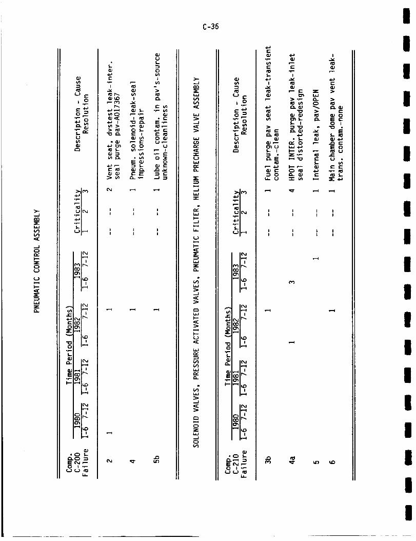
-Jnn
U')
...=i0
I-"ZC)0
(..)i.-4I--
:E
Za.
O.}4/1
¢") E
0 -Isi-
S.. nr*(J(/I¢)
_nP_ m_m
_u
_ m.--'_
IC_,,l
ICX,.l
(_.jfr_'_
00__-,-_
"" IkJC)
"00 i,-.._
opS.-
Q') I(_Ja.
i...=1
CUE _0 'r"
_- ,---I i_ D
1_,,,4
iw-....¢
G_4, C) _
E C_ ,"-0 I .r-
U ¢..) _i.I-
(U
%,-
O(/1
Iu_
r_
r- u_•r-- (/I
• EI::: .r-cO_--
r"OO,'-
UI
0p _--O
OG) e"
E
U')
>-..JC_
c_
W
...J":C
(.9
-r"UI.*.Jr,-
i...q..J
-r-
W
_.JI.,-4
Ui-..¢
=E
L_J
r,
L_J
-.J
W).--
t...¢h-
W
(,'1U_Wr,-
W
..Jc_
I,..-4OZW--JC)
C-36
U
=o
U
mm
U ICX,I
_U•_ m
I_m-¢
(_lr_O0
'_1_)
&/I m_i i
COO
ar,._
" I',_
.pS-IlJ
_ _1:_ _"
_. ,.--,E O,J ,--O I .P
¢..) (..) _:1L,
•r=-{/1 r--.E El_l ,PS.- m4-) '-"
v G_P E z
CU _ i.tJ
ul C)
S,. I
G_ • S,- G)G,) ,--" n_" C) ,-"
I.- I I'-" _
_ 0 _ QJ e'-
I I II I I
I I II I I
I
p.-
CU
0
0 m
_ E
I-
u_e- e-
m
Iiii
m
iI
i
im
i
iiI
m
m
m
I
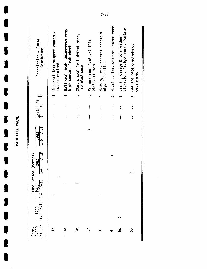
!
I
I
I
I
I
i
i
I
I
l
i
I
i
I
I
I
i
W
,..i
...Jhi.--_1.1.
Z
_EZ
U E
_._
L. eY
U
.1._1oP n
UIC_Io_ l,4,_1
IC_,li!--(I I
CO
"-_1_o! i
&/1 iP-Ie- i i
•i-) L'M Ir_EO0
I_O
01 ,--4ol--
(U ICM
; "12
{U
E v...4 p-O I .P
U P'_ IC_1.i..
I
4-)EOU
UG)
I "_
n_ E(_ .P.
"- E
_-- (__4.-)
f,.'_
E O
(J
1=
.4.-)
E
I.-jE
0
0.)
e'- 4._
Ip- e-
EOEI
U
I
i_ U
oP i1_.l-)Pi_ O
_#1 oP-
in-
.p-
.r-
I
P- _.)t-
," 0I_ r-(U J(_ {/I
U
C-37
EI-
_..•l_ _"
I 0
U .¢.-)U
'P I
OI¢-"_'E
(U
0e-l
U
0
)0r"
I
e-
o
iu
0
dE: .P
(/1
_de.-
e- 0
0 m
.p
E
0
•r,- _
_,1 .P.
0EI
(UvU
U
U
E
El=•P 5..
.O
I
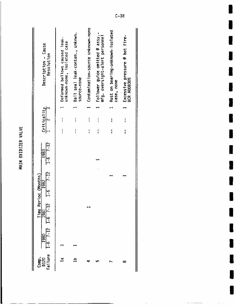
lad
--d¢C
nr"l.l.;N
XC)
Z
(C
GJ¢/I
tO
¢...)¢-
i.o(.-4-)O -Ir..-
_o
l_n,"fJul8J
I,Jl_
wl-.,!._ m_m
Iv--'4
IC_,JI11=--'1
I I
IC'_J
| m4..) _j Ir.__0OC_r_
0 m,,--.ior.'-
Q,)ICXJ
WE _0 'r_
o_ _1_
I¢_,J
I.I-
I I I II I I I
I II I
I II I
o
°r'-I
0
v¢,..
I
c-of=-1.
¢-.o
(/t
C-38
_..0r-
icl
I_u
of.-
4-)0
¢)1.---!
_n
0
>aO",-0_0
(j,_.x (...)
L_=3
O0
I
III
III
Il
II
I
I
IIII
II

iI
II
I
II
II
III
I
II
I
I
I
l,J.i
.J
N0ig
i,=-4x
r,,-
z
I.¢J,.,,,Q.
,..i
IJ_
¢/1-I
u E
¢-4-)o :_p-,
{J(,/1
r-,,
,6--'1
d=-'l
Iv--4
ICM11--'4I I
n") If",,QO
"ql_| |
i-- ! i,._ c_,l Ir_
Z,,--i
0 u,""_opL
_oI_E
I-- "_ I_D
iv-,.t
*_ S-._. (','1 3E ,.._ r.-O I -P
U _::) io1.i.
i
4-ar-ou
uop
L
c-_i
n:lo,J
f...
r--n_OJ
e,,,--
e.n
EoEI
(IJus.-
O
E
o
i-
I
3=o I E
'- _ oP .p.
E _ c
r- U E e-cO O U
S.- U _._ .1_
_n {n 4-) E ¢l: S,.
e.-- _ 0 ¢JO e'l P" I
(4 E :_ V),--. S.. O _-
P (1.) (1_ E P-._I" E 4-) -_ P U
C-39
oo.) ,i'o IE _ Eo "_._ OE (1.; s.. -P
u 110 _ NS.. U .P
O S.- 0_ --I_n O E _n
S- E _nE I- O
O _- _.E .IE _ I-
t" 4-) I >0::3 (]J _J 0_I
O OP" ::1 (_)U n_q.. 1.4 =::)
I I I I II I I I I
I I I I II I I I I
•--; _ ¢M Or) _r
c_l !.-4
i ii i
i ii i
eli
4{Jc) _D
Of-4/)
Oop.S,.
E.i-.4-)
..1=4-)
o
EO
.i.a
e-I.p
4-ai/1
,p"o
_ue-
4.a
E
PUE
l.-e:l
IAev"U:::)
Z
I-D¢1U
.p.t.a
I--U

W
W
XC)
IllZrV
I.I=I_::
I..I.IN
I,,,-¢
XC)
O.;
r,..)r-
,.o
0 "_p-
_o
U
OJ
i,_=1
1_ IP-..C_
i_...i
_ 1_-4
,_ _,.1 u_'-
O_:_::_
"" lU:::)
0 m,_4°p
E _0 'r'"•f'- _
i r,,,,,¢
• _ J..
E ,.-I t-O I .,-
L_
C3
O0C30¢:[!
oq
_J
e_
>0
C_
I I II I I
I I II I I
evle_
,_r _0
C-40
l.m
.--I
l--Z
C:)C)(J
r._la.l_C3=E:
:E(.J
OJ¢/I
U E
,._r- .i-_o _
;a
U
>,,t¢_.4.mn_n_n
0 IC_,,,Io_•m,-,I
IC",,,I
!('") Ir_'03
hn.I
IC".I
I I_ CM It'%
O_
'_ F,O
0 m_
f.
mE
| m
h=,,,_
""_ |_,D
i,_=1
1.1.,,
IP00
&)
0f.
I"0(U
00
0 _-
I
0
r-
UI
i-04-)l-_J>0
I.-I/I -P
¢-0
!
E"0
t-
I
{U,--"
I
0
f.
0
I
0•,..- _j
E
0,-"
I
Ili
IIII
I
II
II
I
II
IIII
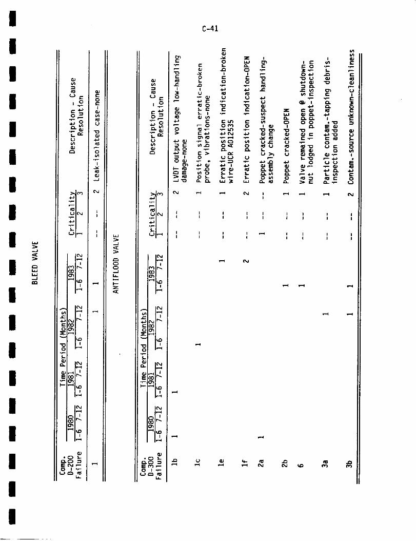
I
I
II
I
Il
III
Il
l
lI
I
ll
l
i.&J
..J
_2
i_J.-Ja2
0 e-
,.o
_o
wk-,,m
_m
U IC'_..I
•O.m'm
l,--'a
IC'_J
(') II"_
A IC_,J
m,,'--q_-- m m
e,Jmr_
rm'Qo
X i"--'q
i,_
)I"
E _:I_ I_'-
'PI 0'_
_- i ,---II_ID
IF,,,,1
"12G_
• C) S,-
E C_ r--0 I .P
I.k.
U
r--
o°r,.-
GJ-.J
v--¢
L.m.J
.-I
C_C_C)
I--Zc:Z2
¢..) (-
°r- r--..0
C_
_J(-v-)4--'I
_m
_mUl_._m.b.,u
?L
r_l_
• |
m m
_e" _,,11r'_
,_... __
I',,_
%.
E _m-.
OJ• (_ S.-
E r'3 ,_0 I ._-
¢,.) C_ rOk_
C-41
CM _ _ (M!
I I I I I I I I II I I I I I I I I
m i m m _ i m i iI I i I I I I i

I.U...J
.-JOQ¢:i--Z
XCD(.0
C0
0
OJ
QJE
U
i. o
ol--
t.)
aJ
_.wl(V)_u
_m
_i_
_mo_m
_mU m,,'-_
I('_,.j
! !
O0O_
•"-'4 i_1:)I !
ICxlI_..I
m i
m I
_lr-.
• |
I_...I
Iv..-i
,-'-elL.l _
°p
U _ a,)0 S....
0
Iv
.--I .--I (.,,,')
! II i
t !t I
L.a,J
,,,,.,.J
ZC_
I---
,..J(:3
ZCD
I---
-.I
Uiv"
(,_)
C-42
U E
_._
,r-. _
T-_U
,,e-_ i
_t
U IC',,,I
,4-,_ !
I(_,,Ile-.,,q
r',") Ir',_
Ii,_q
,,,,,. ICXJ
e-.:OO_
"_ ND
.li
S...
_.. I('_I_.-I
E _0 jr"
_._ka,-
I
OJ tO 0 "Pt_ O 5- Ieel -- QJ'_2 I_
P'.0- U _=1 E .,'-0 E "P S ',- S.-
f,- ,-- E %,- G9l---O ¢; }eC3 I- .i_ C) ,_-_ "__ I= cI_ S...QJ QJ
i i e Ii i i i
i i i ii i 1 I
s--i
I
II
II
I
II
II
IIII

I
i
I
I
I
I
I
I
i
I
i
I
I
I
i
I
I
I
i
F.-,,=C
I-.-U
w
,_J
Z0,,--4
u c.-
L.,}
4--"1
fll_l
I I
,'-41_D! i
Ih " •
_ _,_1it'_
Ogr_
,,_ n J
op
I_,,I
Ir,,,,,l
Iv-,,,,I
Iq_,,4
Q.I
E C=) ,--0 I .P
i.
M
(M
xo
(u
_J
O-e-
"o.c:
e-• r-- •
0 u
_'- I(u
s.-"_" 0"_ u
cM
C-43
S-O
S-_J
&
!4_
_p
¢,_ e,._ O
u
° dP
u,.l_• P- I_
Ic-O
e_¢-
.p-
EICl
0UI
S-OS.-I.-w
4-)
I.-
P" 0(/) 1"-
(M
(M
E
4-_I
f,.P_
"P¢3,Cl,_
¢0-¢3_E
JEU,Y
4.._U
:_ O
0
!-.-4
_r
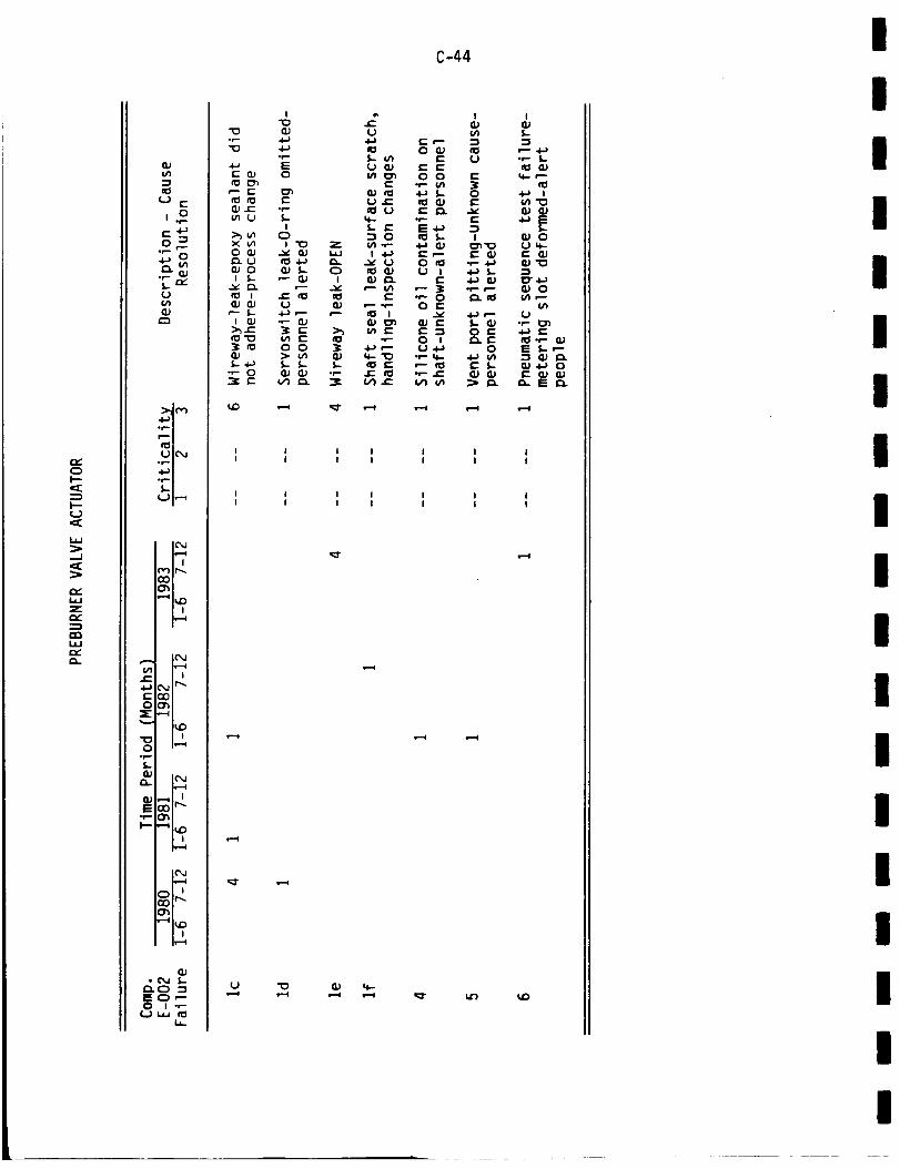
,Y(:3f--_E
i'--U
i,,
-.J
i,iZ
--jCaLIJr.1Ch.
opq3
n:_ P EU E _l_
e_.C:I .__. ul U
_ 0 O_
5-+J°_" O
::_m tD4,,,,oi
iUle, J i
.4._i
i...i i_... 4 Ii
IC_,jis._4| |
iv-.....i
¢/1 i_-.,,,Ii !
Em
,,_ n u _
i,_,=1
I-- "_ I_
°p
L,I-
I
4_°p.EO
e-or-
IC3
,-, (_ I.I
U
_- ¢-- 5.-(3.) "P
I II I
I II I
C-44
I I I II I I I
I I I II I I I
III
IIII
I
II
I
II
II
IIII

I
I
I
I
I
I
I
I
I
I
l
I
I
I
I
I
I
I
C)
I---U,cO
,._]
w
Z
u')
U c""
C: ,+-;
lB.
(JLrlaJ
::::bJ('_")
_a_m
t(31U I(",,.I
o_ m
_m_ m_"--_
I('_..1I!.-,,I
r") Ir,,._O0
,--01_ 0u !i,v,_l
IC",,.Iii1..-,li i
{,_,,.iI1"_C_0 {:Y'_
=E:: ,--a
"" I_0
0 u.,-i.1,,.,.,.
,,.,, IC_,,.I
uE
i-
"12(U
• (:::) _
_,-;,,.--.u,-U 1.1,.I _
L,
I I Il I i
I I II I I
C-45
,-_ ¢M (%1 i--( ,--I ,,-I ,--_ ,--I
I I I I I I I I II I I I I I I I I
I I I I I I I I II I I 1 I I I I I
¢%1 ¢M ,_ i--I
e--I
,--I
,-_ ,--I ¢%1 f_l f_l _" _r
I

.I,D4-)f-O
(J
I"
(.3cC
.J
..J
i,
Z
QJ
rO
c.-._0 "_
U
,,,o,_m•_ n_m
U I (",,_o_ i,,_b-.,n
_mU F"-"I
I0',,.IIt'_gl l
rl_,')I t._
i iiv--4
l@,JIJ1 1,--4
i i4-_'E,(.M ir_
IE ,-'_
,,_ i J
L-
_1,-.:E
|v,==l
QJ• C3 _-
£:),.,--4:3E ,.-_ ,--O I -,--
U I_J to
L0 g
P
0U CO 0
Q_ E f,- "t3
E *" _-o-)O U ¢-
G.) P_ f,- O_ ct:lf,- 3 E
"1_ 0p •
OU .4-) l"_-- 0 QJ U
L I _ I
:30 • E•_ _ "[30U'P >_ E
I
I
S-
;4-
4-)lJ1
UEn_
S.-O
S.-O_
CL_
(/1P-Z•P I.l.I
4.a
Uopf,.
E4-_
JEI
I_e.._ u
_-_ I I II I I
t I I II I I I
Os--(
.-M
(J
s_4
4(
C-46
,z:moto-
o,pf,.
E
fl)
0
00p
.pS.-
..C:
0r',-
"!PU
.p
(.,3
Z
opi.=-e:lU
°p
.p$..
U"k
I
IIII
II
II
II
I
II
IIII
I

I
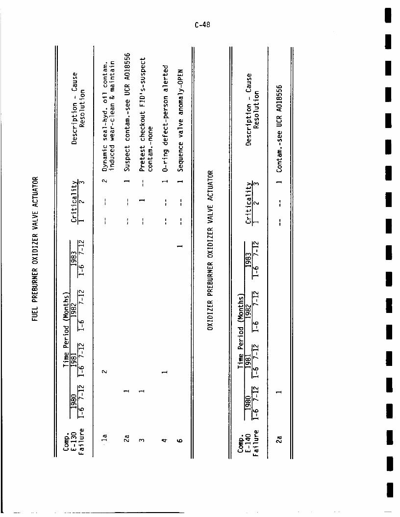
fY0l--
(.J
id=i
....I"=E
a::l.¢JI'Ml.il
X
L4.JZQ::
IdJ
C_.
.=J
=3L4,..
aJ1,4-s
¢..3 E
(.-4--)O _
U(,'I
:>,,J(-,-)•.Im' !
ro!
i_=...i
i r-.._
t==. . ._ _,1 ae'-e"00C) O'_Z ,"
.f.-f_OJ
l(",J
E _:)'_
• f,- _
|_,,4
OJ• 0 S,,..
l,-_ fY) :3lEE ,--J -"0 I .r--
L,_
t4")• c'- 14"*)
E.r- 00
•_ .4...) C)
O.r=-
E O
•r- c_
E u Q)
e-- .._ m
aJ "oC:I. aJ z
4..) L4J
_ C)I r--- !
_ 0 E
0 J G)
U e- _I "_ _J
G) e- l.- I_"_.- 0 i (].)
" (.J C) i._
I
@,J
i i ._i i II I I i
I ! i i iI I I I I
s-.=l
C-48
OIn
l--
w
-J
N
X0
L_Ze,,,".--_en
n,"
XC_
_J
n_
U
,.o
i.m,
(.b
_J
_tvl4.._I
(-)l(%J
rw._I,.-._
i'_} i1,.,.COO_
_1',0
I&#} i_,-(em I i
._ C,_ It'"e'COOOh_-,_
I,.-
QJ IO, Jle,,,_
"P 0"_
_J*0 f,-
0 I .r--(..) _.j ¢1
L_
If)O0
0
U
(U_UUlI
E
.l.aEC)
U
II
II
(M
I
III
III
II
II
I
II
III
II
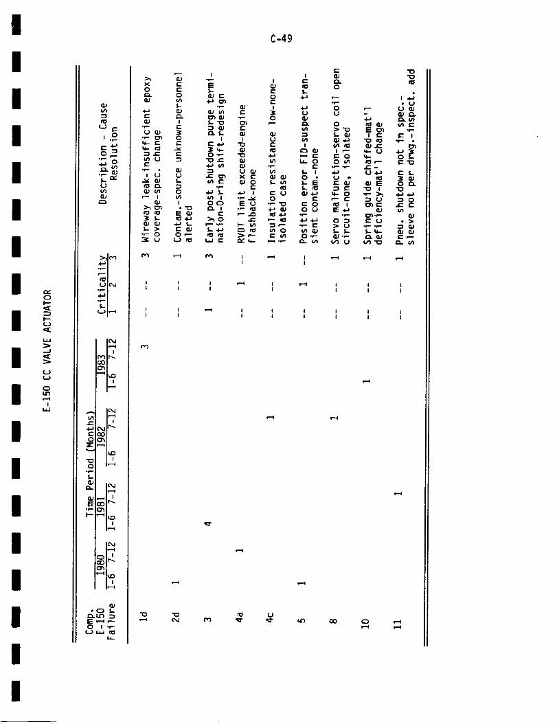
!
I
I
I
I
I
I
I
I
I
I
I
I
I
I
I
I
I
ry-CDp-
¢.J
I.¢J
C.)
CDu_
II.¢J
¢/)
a_
(__ (-
S- ""(J(11
C_
::>Jr,')
,_,
rOlUIC'_
,6-,i
[,._ I,-'-_
1_=..4| |
_lr-.mO
t'-- I !
O=h
I_D| i
"OO I,--4
or,-L
_2. IN
0J _oI_E
i !
• C_ I-
E ,-4 ,--0 I .P
U-
xO
.+_
_Uor-U (i)
r"
I Uv _j
I
-_"_ U
C-49
Ie--IOI-
4-)
U_U
l/1-I
IC_ OJ
(-I_. 0
I- I0
c-
O U
.I-) ,I-_
I ,-..I II I
I I I !--,I II I I I
_T
I l II l I
I I l I I II I I I I I
s,-I
UI,¢')
s,-4
Qvii
I

i.¢JiJ.-I
I'--ZC_¢J
I
U
l-
.p. ¢-0
l_.e",P- |
¢D 0
-I(J.l__j.r-X .=i(_I l.l
I,-.0 o0-,
or- 0_I 0£,_r- =
_..
0
_..(U0.0r-
E,r.-
II-" ¢I
=r- 0
=p-
1.=)
e==l
C-50
I
I=.¢I
Z
r,_
| ._-÷ v)
¢/!0
r_ (Uc"
_- 00 c"
I N i N II I I
I I ! i II ! I I I
cr
I-=i
o') op.
I
III
III
II
II
I
II
III
II
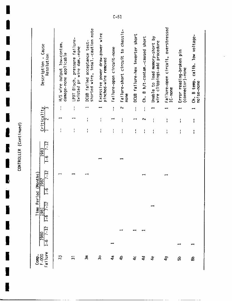
I!!
!I
!
!
!
I!
!Ii
I
III
I
-i(.-
,p.4J¢.-.0
(,J
-,=I0p,.-I---ZC_C,J
QJv_:3
0 E:
p.-
._ QJf,,... "YU
:>.J r_.4--*1
_'I_I(..) IcM
L.,) I,-.-I
IC',.lis-..,l
("0 II'.-.O(3
'-" I_,0i i11.-.4
IC',Jli--.i
¢=. , i•0,-) O,,Jtr'"r-.QOOO_
_-,--_
•_ n JO i,'--_
.r--LaJ
_. ICM
E_ O0 Ir_°r'- _
! !
IC, air,,,-I
Iv--,q
o0 I--
O I .,--U 1._. _
I.l-
C-51
"_ u'}0 _
I op_J I E 3
E :3 IJl.P _. U_=S r'- GJ (_4-) 0.) GJ
E _ O I_ O O -_
U_ I U I I I -I_
_ _ "_3 _.- l"_ _ _ O
O U r_ P'- _ (U :_ O 1.4
(_ E (/1 ._ _ I I I
V) E C::) .r-- "-_ O U E .P -P
r" E
I cMI
i _ II I
I I II I I
O _ ._
_Jt'-Oe-
.._ >._0 _ .._*- 0 GJ
0"1_
_- _ t O
-- I I= _
I I= cOO O E
°P _ 4-) "P
_I- QJ (J
(j e-_ £::.p
I I ,-_I I
CM !I
I I II I I
U "13 (_
"X3
{/1¢4
4.-)
(U>O
.2
I-
t'-
!
l-_Je-O(..
IU
e-.p-
E
O
t O
E to_ ,_
0G.' 4,-_
f,,.. ,,,,,-0 C:S-, 0
I.,.I _,=._
,.,¢b
I
f.,-,0
0
U
(_ O4-_ !--
I
(/)
!
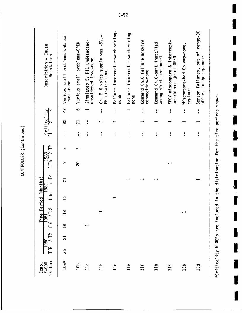
(U
e-°f=.
c-O
Uv
C_Lid....J
0
I--Z0
¢.-
c-O
0°p.
5..Q_
G.}E
°_
,.o
p--
0
00
CO
i i11--4
IO, J
IO, J
i.--4
°C) _-r'_ 0 .-iE C) ,--"0 I .r-
U-
E
0E
(-.
I I(A I_E E
r--- r-=-
0 0
2- '--
E _ E
0
0 _ 0
C-52
I I
I ¢'- _-• .r- ,t-,-
i _ S.- f..Z "0 C_ ._'- .P
__ +_
_ 0 0
0 _.
I _ U U
_"- 4-_ t" 0 0la_ _ I U (.,)
_,I _.. "P" I I
E u_ -- ._- _- .,-
I iI I
L_
O0
I I
I I
1 t ! II I I I
,-N
,,-.4
_0
0 0 _'_ ,-_ ,-_ ,._
fl)
0
I I I I II I I I I
I I I I II I I I I
s.=-4
0¢-
0°l=-
E.p.
_..0
N-
t-O
=3
.p.-$.
.p."0
e--r-
"0_J
"0
p,.-¢.J
.#1.
.r-,
e_U
.p-
l.J
IIII
I
I
I
III
I
III
IIII
I

II!
IiIIIIIII
W
It
IIII
"0
'--sE
0U
n.,,i.l.i._1_Jc:)n,,.I--ZC)(_)
fJ_"-sn_
¢"-') c-
,.o
0 -!
U
_OJ
f_lUI_
J ,r,') Ir_gO
| ,ii.-_
h._4e"
e'CO
0 I,-_o1_
QJ
11._4
E_ _ I r,,,,,.
| J
_,_-.
•-.-4 |_
|_-,4
• o 5-
0 I .P(,J U- f_
U-
C-53
L 4__J_ c- 0 QJ "_ z
U or- t.,-- _ _ 0 I
E _ N .._ L "_ I I,-I _j _ ...
C) n:J _r_ _j -_ 0 4-)I 1_. I1D _ ¢- _ _,) 0
E E 0 _J _:_ ..1=- 0 f_ _ ._ "10 _1
LL .P" _,_ 0 I L 0 fl_ t'-
E Q-- I _- P" or-
> I _ I _ 0 3 E l----P "I_ 0 U
_ _ C) O (..).P _. O O _J .E: E: 0 ¢1 _.
e,-i
I,D r,.,.P-4
n,,') h.,.(.J
r,_e-,,4
e.-4
Gor'_
4-)
0e-I/1
0
of--U
L)I
0 _"5- 0
I(1,1"10
I_ 5.-
PO O
ell¢M
!-
4-)r-
E0E
0
U
UI
h f-
_. a
e'_ 5.E O
U
¢1e-
•J_ O_:_ 1:::
or-" |_" .1_
I
or.- 0
(..)
t.-'_0 I::
0
_Ju'l _J
N
i
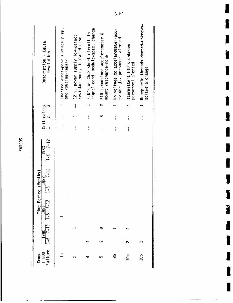
O0C)¢_)C,_
¢lJ
"I
¢.-) c"
,.o4.a
_o
S_n_"U
_;_Jo _),,.i-, i
rillU IC,,,J
,.o.,._t
f,,,,.J i,,,_4
IO, Jit=,4
cO It,-.
I i
IC_
-i_ L",JIr'_EO0
_-,__
I_0
op.S,-el)
O_ IC_aii._l
Er-o,_
i---i ,-._1_| i
i_=-,i
,-,4 i_ D
I1)• C) _.-
_'_ C) -_E QO ,-"0 I --
¢_) b- _
c_
U
-I
0 -t-O_:_ _::__I
f,,,.
.p {,,-
U cO
C-54
I ,--_ ¢'_ ,--_ _I
I II I
I II I
un cx) C) C)
IIIi
i
IIII
II
,|
I
iIIIII

I.
I
II
Ii
i
IiI
/
I/
i
i
1I
Ii
r_WI--
Z¢__
c'_¢..)
E
L rFU
-e.-,,i
I'I_IUIC_
,.i,--,i
I'+'--+
IC'_.I11,--4
r'_ It.....
"--+ IUD
l,l,,_
IC'.J
1,- I I:%1It'-
E::_0
,_-- ,,._+
I,,O"E) . iO i,--'+
•I""I,,,-03
r.. IC",.Jl<l.--i
_:) Jr-,,.EoP" 33
i ii,r.-t
IC,4
:olr---
Iv-"_
"(_ I=
0 I -P"(,-) (.0 _
I.,.i_
gO
It')
Ic-O
•I,,.-
U0#EEOU
I
i+_O
0J_n0)
4-) i_P'- UO>'13
I:_- ,--
",1Q .P-
_D
C-55
r-.-Io'_s.- (_{:_.r-
o1-._.I-)E Ol.- E
,--&_ E
E G)_ m
Es,- _.
e.- 4_)
U
GJ
op-e-
EO
0J
•-I 0J
O 0JE
O
-',.,i
op. i-"
_+- _:
I_1 e"s4_.f-
+.-4
E E IO O I
I I E -P O(" 3_ 0 "
--s 0 E 0_
•,- e- _ .,.. 0 c- E0 --1 I 4-) I,.,,. IE _ .,_ ,._ E 0I _ U 0_ 0 UO r"
-I-+ _4 I=: 13_ 1::3. _ 03.P---i "1 I_I E I _ P- -I-)
O I -r--U ._-- Jr- i_ r'_ I 0.J
(.) I_ _- U _,- _ :3 U r" E0J 03 _ P _ I
-s • _. C3. 03 .PP- 0 E
"'- =_ I 0 _- E I_.-,-
•,-- e- U .,-- r"s .I-) 0 e-"_ 4-) -P 0J .1-) ::it'- O =1
C_ !- :_ w I- _ _-) _,- _ E_ O "_ _- _- :3_-- _ 0
lu- _ --I _ L_ E 0 0 CY U
I II I
I II I
(M
I I II I I
I I II I I
('M
{M
I_ ,_ _ _ _- If)+--4 _ i-.I +P-4
I

i.¢J
I_JZ,Y':E-r
CE(J
t--(JI.¢J..J
QJ{/1
U (--
,.o
p..
_o
U
:;_ (Y)•4-.-' I._|
UI_,I
4,,,,I |
I L'-"t
I I
ic'xJ
¢-- ! I
E_
=1_ I I
0 I_'=_.p
S.-
C_. IC, J
t=op
0"_
I,-'¢
op-
I
E E_ 0p,-
p---
"OI:_ e-E _
I
E Q.}
0. _ _ 0
I_-_- E i
$- _ 0 E ¢-_ _ _- _ 0m- __ C.9"0 QJ
0 _ U¢-- .p.
•_- ___
I _'- !
_.- > _ O 8_C) -P-_'- ._ E
I 4-_ U O
_._ E i,+_ _- E c..-_ O O O
"_ E .U',-I
$-"O QJ _
{J or- oP-
0",-" (_ 0
C-56
II.- ._1
£1. U..O
_= O.p. (.-.
E
O_O
f,_ (_) f,_ _-_O _ O .P
E O" E
O O O _(.J .I.._ (J E
I I 1 I _ II I I I I
I I I II I I I
I II I
CM
I I I ,PMI I I
I I I II I I I
s.-.1
0JE
"00
o_
f_
E
4-)
_U
0
c-O
-.i
M.=..
I-4..)
.p
"(3
=I-.-
QJ
.=_
Ur-
CUI-
U
Z
*r-*
¢IU
op
*p
I-U
III
I
IIiIi
I/!I
t1I!iI
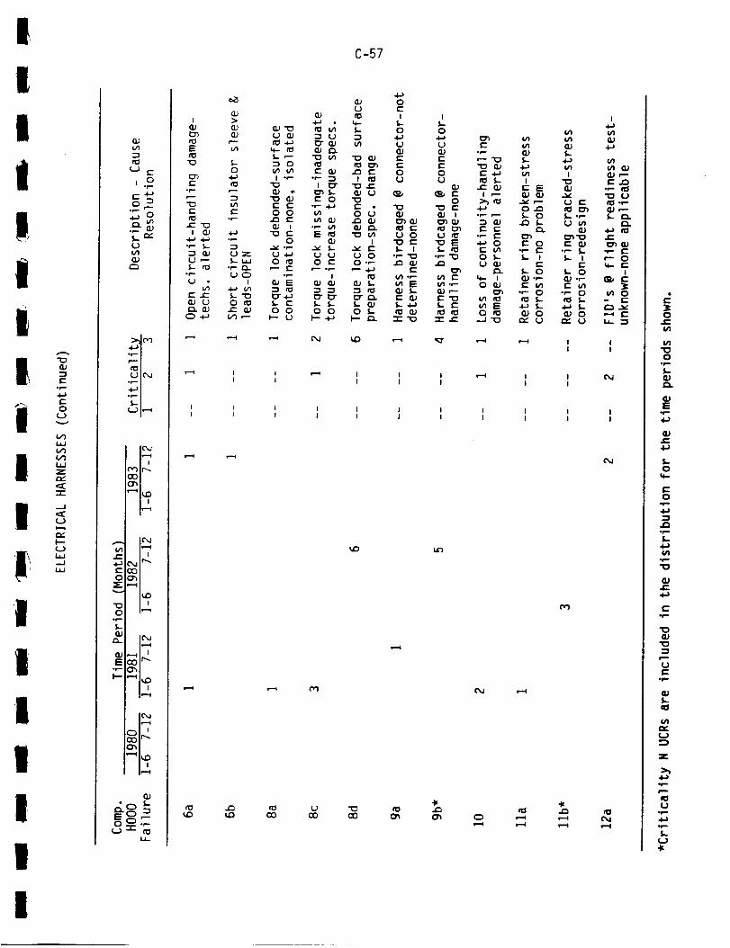
I
I
IiIiI
IiII
'J
I
I
II
II
0
w(f)(._LiJZ
"-r-
.-J
(._)
..J
(IJ
rO
•r-- (_
L)
(1J
:;:_ (-v-)._=.,!
UIc'_
•4.=-,i
OOOh
'--_IuD
,,...., ic'%J
..C::C'%11r_
COOOOh
IUD
O iv-._o_L
E _m-.
I-- "-_ I_D
i_-.4
is--4
Oh
, |ip..=4
-'r-i.&_
c_
t
E
"_ 5...-0
•,'- ,_
e-- t-
e--_
_ 4-_ o_--
t" e-- L"_
_.,_,
5..,--0
i ._,-
e- c-o o
o
o
._E
o o
-i-) •
"5
"_ ¢/I
¢'- _j
113"_'_,Le" 0
o_1=
v
0 e"
!
0 0
C-57
(.)
5.
t cO
(X.) (.)
o_Qj c_
I
O.r-
0 5-p-- r_
t_
_D
4_0e"
I
0
l.J_Je"I=0
"0
tJ 0"0 e-_.. t
°,- '=0
or-
-,,m. o
I
04,_L)glJe"
0
_J
0
"01:=
Cn
r-.. o
,q,.
g=n
.:,,-,--'O
_" 4.-_,_ f,."" (lJi P'-
•_ ,--e,- c-
op. f,-•_ o
o 5.-
_J -.1_
o
f,_
i
0 r_I= 0
_-_
e- 00r- _-
te"
L- 0(]J ,_-
0
(.#5_n_J
i"0
(3_'0e- _j
Ic-o
Qj or-r" u_
or- 0
_J 0
,m=l
i
_j,.-
•t- l'_"0
sin'
•6,- l,"--'-- 0
I
0
0
0or-L
S,p=.
WJ_
I-0
0
J_
4_
"0
"0
U
,fn
I/)
i.J
>_
Utr-
M-.I-
I
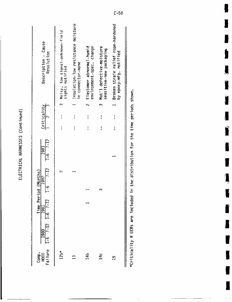
E°r--
0(Jv
V_
V)
WZr_
-r-
..J
U
r_F"-
L__J
c'-
r---
Lr'_
U
a.)
.jlJi
rOIUI_,J
.4-_1,_1
,.-4 p,_
i,.--4
E_
O i_-..ior-.
I--" "'_ |tD
EO _
O _ "-U _
"t3
°r-
IE
OE
-SgE
I
%
°P- °r-
°r-
0 0r- E
>__n.c
0"_Z _n
co
C_
c_CM
C-58
E
I,,-¢}r-
I
0
o_-
0
•,- _:_
_- E
xe- O
O
rn _
_ M
Oe-
O°p-
(lJ
°p-4.1
QJ
4_
0
_.-0
.p
oli
_n
"0
QJ
E.p-
"0
"10
riC.Jt-
.f-
n_
/21
U
Z
4-)op
%U
.p
I
I
I
i
IiI
I
|
I
I
!I
I
I
I
I
I
I
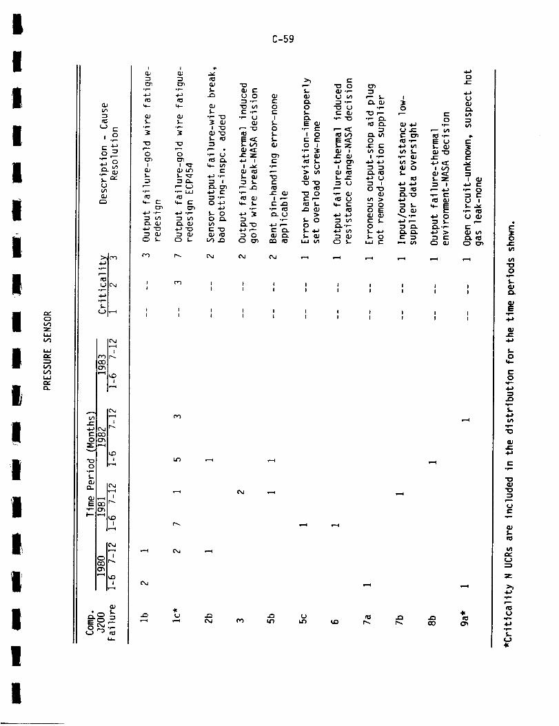
!C-59
I

G)-It-
op.
t-O
L)
C:)V1zW
1.1.1
V1V11.1.1
Q..
..-I
L) l.-
,.oc.-4J0 -_
p-
l._ n"U{/1
.i-,i
UIC_
.e-,io_ i_J
11_-.-ii i
COCh
! !
e--
E_
O h--._0r-%-
Q) I_.J1_...4
E0_-. _
I-- ,-'4 i,_| ,if--t
lea
i i
,.io _-
o_._Ur'3 _
I
-5U
0p-
U
E
0i
0
U _J•P- 0
UO_
E0r-I
E
0EvE
IEO
.i-.-
_+.._
E
EE
,._ OU
£-0.._,
._--E
c_
t_O
r--O
U
I
E_2..0
E
O._-)E
EO E
0
0"'f,.- >
E
O
C-60
I r,3 Od _,_!
I .i_ II I
I I II I I
C_
"k
C) C) 0 0 C3
I I II I I
I I II I I
s..-i e-.I e=_
0J=(,n
0,i=-$.
Eor--
_,-
S,-0
0
4-)=3
.pS.-
"0_J
PU
.p
_J
U
Z
0p
U*r.-
Ip$..
U"k
I
II
IIi
i
!II
I
I
I

I
II
I
tI
II
I
giI
ItI
tI
0
Z
I.J.Jr.,."
I.JJ
I'--
-"s
E
0 _
.p... (_)._...."."L.}
a.J
::>.J_,')._-Ol
.4.--'1
L2 |_"4
IC_,Jl?--,dI I
('_") I r-..COC_
i i
OOh_- ,.._
O Ir-.._,r-£.
E
I--- "_ I_I n
leJi_=-i
_n i
°0 £--
C) I "P-
C-61
O,J
c_14.-
M
.Wr_ UU
I
E
,r-
"I_ "I_¢"-
"- I,..I ¢I
4-_ P"oP. tl_
U,'--I,..
U [''0
f,..C_QJ
s-,.l
oe..f,,-
U
I
E0 0
°P I
U
0
Oop
i4-'}
0I
lal(U
U
0
S-Oe-
e-_p
o•_ I
o_"
U
{I_ oP-U
•" _..U 0
e_e.-
e" e"
0
N "I_QJ .r.-
f,,.. "_'_' "_ i_l I_
I f1_ _ I_•4-) .P
i_.U .i-._ OJ•4_ 0._ "r=" "tO
0 U U _-
•,'- .0J U I=U e:F
£.- _._ I_-0
I I II I I
I I i I II l I I I
0!-I#1
{/}
0.f..f,.OJ
WI=
.y=.4=}
J_
5..
14=-
.,f=.
(/I.p"I0
.p
"I0W
r=.=.
S.-nP
,,,.-U
Z
.I=-
U,,f..
5-
"It
I
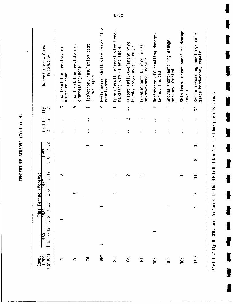
"0
(--or-
f--0
Uv
t,/')
C:)
.:,..I.l,.IV')
i.ip,,..
I'--
P.
I--
C-62
r-_ _ _ 1 I I II I I I
I I I i I I 1I I I i I I I
U "0r-.. r'-.
QO
cM
4( 4(
0
"00
o¢,...S-
Q_E
.I-}
S-O
w-
O,f-
S-.l.Ji#1
-F-,
Q_.c
.f-,
Q.)
Pu
{/1
u
z
.i,-
its
.e.-.l.a,,f.,S.-
4(
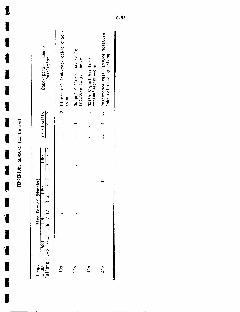
I
II
IiIiII
Ii!I
IIIII
I
Q.}
E°_
E0
U
t_
0t__r
t_
--_
CL_
X
O_t_
L) E
,.o
0 _
S_ m_
L_t_
O_
"6"I
UIC_
"¢'_I
| IIr-=_
IC_
e" C"J tr"
E_
_-,-_
I_O
n_0 i,---_°p
ll.-4
E
| ,
i_=.=I
_t,z
"11,,,0
i,e..-i
• 0 l-
0 I ,P-t.) "D _
_..
I
UcD
U
U
x
0
!
Cu
%U
0_.-
U
r...-
ct_M
OJE0E
cDU
X E
0 _-U UI
°P" I_
S--
t--_ U
S,-
•r- 00 ¢"E II E
0
•r-- t-
O 0Z U
Q;S--
°_0E
I
S-
.r-¢1
I.nQJ
QJ_J
°p_n_J
n,."
C-63
(L}
e--
U
IE0._4_
U.p

v¢..)
I.iJ1.1.1
O--Jla-
E'_" O
r- _. E
4_ _ EU _ v
_. "-!I/I _-- I
rr_ .,- 0
4_-1t-
OI/1E
E0
t'_ .r--u'l .l-a
I f---
"-!
.l-a I
O EO
U .f-°p 4_1
f,- I.-
C_
r,') ,l_ ,c_
C-64
QJ
E E
Ee-U
"-I
E I
•_ E•r- _j-s u'_¢J _.n
I
e- u
_ u
t_
o
w
u
FJU e-
_ 0
U
I_1UIC_
r_ll_00
_I_D
11-.-4
°f-
_J
E
t-- '-_IUD
lea
_01r__h
| i11._4
1:=00,.--0 I ",="
U "_ IOI.I.
I I Il I I
I I II I I
rO J'_
I
II
I1
I
II!
Ii
!I
;
III
II
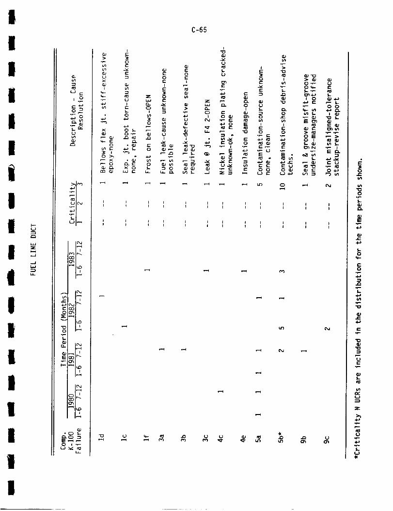
II
IiIIiII
II
II
I
II
i
I
I..-U
LI.JZ
,.J
..JI.,l,J
I.i,.
=3
(.,JE
j.o
0f--•,I,,J O
Lnr"(,Jt/1
4--,i
UIC_
...-, i
u I,-'-
ICX,.II_--I| i
P') Ir'_COO',
h,,--_
V_
= _1_o=
*r--f,...
E r,--0p-
,--,_
.Of,,-
0 I .,-
I,.i,_
"O,P--I
L,)
C-65
u,,- I_ •._ U (,,.)
i--i
O
C'M
,,,..U
IZ) "_
O •,""OU,,-
i 0
f,..•r- (_
tel
0 E0 I
_N
_'_
_ E
¢1¢J_.,m_
I.-0 0
I•_ _..
t-- (U
• p .p,.
¢n I.-• P- IE _-
"-,,1
E U
O4-)i-_ V'l
CM
C%,1
(.,)
3:O
c_
"OO
.i,-.
E
&l,-.
0
O.p
,,f.,"0
_Je-
,p
_J"I0
U
,,f.,
_J$..
f_
U
Z
,pP
U
I

_U
{.-°m-
c-O
Uv
F-
Zi..-4.--I
-JI.iJ
LI-
(U
(J c-
O "_r--
._ QJS.. (:K(J
E_
b.M r_).+_i
(..I I_
IcM1_,,4
'-'_ hD
i_,..t
_,j Ir-...E_
_ I_:)
°p
le,-4
E
i i
lea1_,,4
"_ ItD
i f-,,,t
E ,.-4 p-
O _-," n_LI._
ET_E.p-p-
E
..EI
Q),=_OL
E
.,E E
E•r- C)
4-)
:3 .r--
C)
(._
E)
C-66
• _- I I _J -'_
• ,- _ _- ::3 .P-E
"_ _ _J 0 E U
E (_ E 4-) _ •P _J_J 0
g ,-_J u_ 4-) 0 U _J ._ I -P
0 l E 11_.r P 3 I_ E E I _" f=="O • 4-.) 0 _- E _) ET I I- (3.) "O (I) "P _J_.- P :3 {" 0 "_ .P O_ "_ E 0J > P C:
t,- O t.- O O _ E L) .-_ EP _ P 0 U .C: I_1 (_ _l E _J !.-"P U "P
(_ E (_ t,- ""-"P "_ 0 _- E 4-) "_ > "P t.- t,-
I I I I II I I t I
I I I I I II I I I I I
.O .O (J (J
I
Op-.
r"
04_U
C"4_0
4-_ U
"_-- 0
_1_ I
0
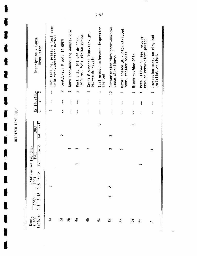
I
II
iI
II
II
II
lI
II
I
II
h-U
C_
Z
=_i
N
C_
X0
:3
U E
t 0
C_
Ui/ICZJ
.+-_l
r_) ir_
_1_=_o_
0°1--5,-
I_Qj .._ I
GJ• C) _-
0 I ,,-
i.a-
E
v'l1
•+J "E_v_ 0G) JE: Z•+-) -I_ I_J
S.- I
0 ,--_.r-
S,-
o_
(J
E:o ,- _,r- I 0 ",-')
i _ c/1(2) (1) S.- X
E .,- ¢+-i_ 5-- GJ I
I -P- c-v1
(1) -l.J "O E ,,+.. "1_ pS.- U P- .,- 0 _0 _..r'_ (1_ O._ ,-- I 4-_ -,'-
"_ 3: "_ _-- Q) S- __ E .,-,-- 0 r'_
(_'_ _ _ C:_ 0 _JI .E r- r_ S.-
v ,_ I • :_ I
rO 0 ""-_ U "t3
U U v) _ S- _l
,-- _ S.- S.- U ,1_ U
:_ --J "_ CL .P U ._
c'_ ,--i ('M
C-67
Zw
0I
GJ-1
"0.r-
8J
0S-
! I I I I II I I I I I
I I I I ! II I I I I I
M
p')
t_
L) UL_ IJr)
i ii i
i ii i
P_
I

Z
Zi.--4
C_¢,n-1fO
¢'-) E
S,.. "_¢,.)Ln
.d_,l
UIC'_._ i
E c_ ,--O I .P
i..) x/ c_
I.i.IZ
0-I--
C.Ji=-0I---
ZC_.
C-68
0 _
UM'I
,e-,, i
_II_I(JlCXa
U I,,--,I
llX,lle--_
I_I_! i
leai,/'i i_
_-4_ £xa II'_
ECO00_
_-,--_
,p5-
h_4
or-- _
I iI_',q
ICM
le=,-,g
G_• C) S-
_._) .-.IE u") ,'-0 I ",-
Uv cO
C_
C_
G_U G.)
V)
_ O e- _,__._E .,- I::
I !_ E _J 8J
4-_ O "O'O
O E GJ GJr-j=_ ,-v" f,.
O
"OO
0p
8JE
0r--
¢iJ
4-_
S-O
O
4-)-I
.p!-
I/1.r-"O
CUe'-
e".p
"13ClJ
"O
U
.p
(lJ
c_
n.-U
4-_
tJ.p4.-)el.-.I-
II
IIIII
II
I
I
!I
IIIIIi

I
I
IiI
II
I
I
iI
I
I
IiI
Ii
I
i"--(.3
(.0Z1=-4.,..J00U
r_
..../,...J0rv-O--Z0U
Ut-
,.o
(_)
'4--"1
U Ic_.J
°_ i
i ifc'H r_
i iI_--1
I('_.b
G_ Ir---it"" I I
E_
.p..-,
N
P- "'_ I_D
_,r-.
E ,'-0 _ID .,_
i
.p.
S-
r_O_L_-_ ___E _-
I
(.)_--
0
U _-
z
0Iv_
(Jt_
U
%E
r_
V_
C-69

<i:
U
I
0
t- Z0 Q# i,,
_-- E E
E _ _c_ 0
_- 0 "_'0
J_ tn nD (U 5.-
C-70
I I II I I
I I II I I
UM
',.)
i,--i
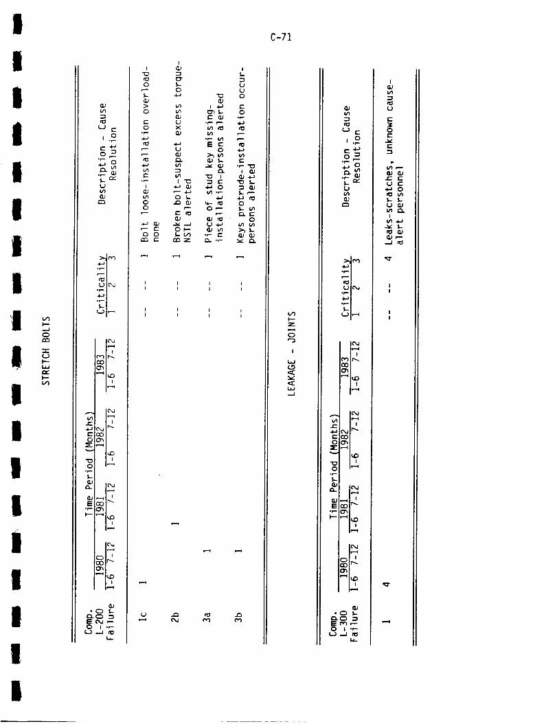
I
I
III
IIII
!i
I
I
II
III
.-J0
_JI---I=_r,,,"I--
Q.J
C._ E
E _0 _
S._ r_L.}(j'}
:>-,I r_
Ulr,_
.+-,1
_v
l{'_J
P") I f'.--
| ,ir=.1
IC'_
L..- ' '.4J Ifx.j I_EC_0_'_
E _:)Jr-.
I-" "-'_ I_
i_..t
_,_--
I_,,l
"Of,,-
0 ! "f-U.-J _
I"0
0
>0
E0
%
E.t-
O0
,-- E121 0
i
0
CL_UX
8_
I 0
0 $-
=%
Ot-.-l,- v'_
e,m z
i
I/I.r--
0
.._ _._
"0 I"_ E•_ 0
0 ,-"
°p. _"
f_
i
U
0
E0
,p.
l,,,,-P
E
I
I,,-
0l,-
,v.
C-71
w_
{-.0
or)
Z
0
I
,,./
E
,.o
U
r-,.
.4.--'I
U le',_
i |
! !
i i
O=h_-._
I_D
._ n nO u_
.p$..
_. ICM
8.1 _0 i r,,,,,.•P,.- _Pi
_|_
Q_
0 I .,-
h
I
I,/'I
U
E
0
E
.E EU E
_.. $.U
I_4J
I

...-I
n_
l/)"-I
U E
,.o
0
rl_lU IL"_
,4,--' I
I{'_,JI f-,,-4
,--'4I_C)
IL"_fj,} i_,---t
_ C_j Ir''-
EO000'_
_- ,...._
lu::)
noo i,,-_
°p
0J12_ ic._
E _0'r'"°r'- _
It'4I,"'--4
_,_-.
| ,
• 0 _--C}.O :_E 0 ,'-"0 I .,-
°_
°p
(J
"I0
0 E
IE)"_ rO
• p. (.)
E
I
U-
r_C-)E
c_
Z0
I--r_1.1.1I--0
--J
-r-l--
C-72
u')
(.-
¢- .¢-}0 _
,,.-,,
:>.d('_.i._l
_1_1(J IC'_J
u I,--_
is..=_
O0
h"=_f.. i i
4._ _.j Ir__": O00'0_
V I_D
_J_. IC_
iS _0 'r""P" O_
IC_J
O_
• 0 I.-
E 0,_ ,'--0 I ",--
UZ _1
t-O
°l--
(J°p
I S-I_ °r-
I-
EE I
• r- -1
m UE _
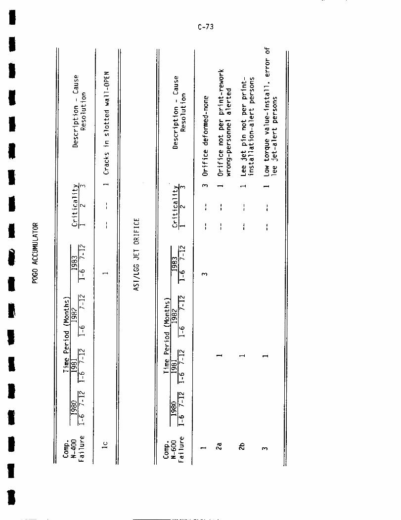
I
I
iII
II
II
iI
l
iI
II
iI
I
0l--
....J
0
,.o
p.-
Q_
.+-,i
_i_
.¢-_1
_i_,
t-
O,p-s-
_l_E _"
QJ
0 I ._
i,
Z
C_I
"0QJ4-a+a0r--
c-°_
tJtO$-
(J
C_
k_J"3
_D
tO
,.o
tJV1
_1_
!(Y) Jr'-,.O0
"-_ I_iOI
i.-4
i.-4
¢" c_ji /
C::::_00"_
i_C:)
0 i,,-,i
r._ o .=iEu_,--o i ._-
C-73
CO
I
¢IEf,,-O
oe-
,.+..0p-£.O
I I I II l I I
c_
I I | II I I I
C-74
(THIS PAGE INTENTIONALLY BLANK)
III!

I
I
I
I
i
!I
II
liIi
I
I
Ii
Ii
APPENDIX D
UCR REVIEW
Summary of Component Failure Types Data
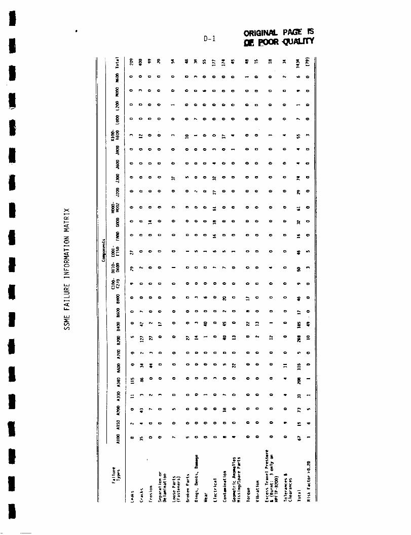
I
I
t
!II
11I X
i"-
C_
L__
r,,,"
,-.q
I
!
I
II
!
i1[
91[
Ip
D-1ORIGIN/IlL PAGE fS
0_ 0 O0_O0 O0 O 0 _0
0_0_ _ O00_O_ O0 0 0 _O
_000 0 00_00 O0 0 0 _0
_000 O O00000 O0 _ 0 _0
__oooo_o oooo __o
0 _'_ 0 0 0 O 0 0 0 0 0 0 k'_ 0
O_O _ OO00_O_ _O 0 0 _
_00 0 OO00_O O0 0 _ _

D-2
I
I
F"
r
I
I
I
F-
I
II I
Stl_ll.-I0_I3BI_qN
I
S3DNW3701
73A_1 SS3DX3
NOIlWBIA
3nOB01
_IX3/gNISSIW
NOIlVNIWVlNOD
lV31BI3373
_V3M
39VWVO 'SgNIO
S±_Vd N3_C_B
SI_Vd 3S007
NOI1VNIWV730
NOISO_3
$_3V'd3
S_V37
LUO,.
6_
,,.I
U.
CI.
>--
F--
66_
r?
,-J
L_-
>-
ram
r_
U
---_
0
gD_
mm
z
I
(_0

m
!
I
I
| E
!
I
I
|I-
!
I
II
II
I
II I I I I I
c_
s_I3N JO _3g_iN
F
f-
D-3
!I
IVgWI9
S_3NO
S_OSN3S
53553N_VH lV31_13313
B311Ngl
SBOIVNI3V
C)Q-
S3AlVA NIVW _-C)¢._)
B3111_ ONV $3AlVA _33H3 >_
dWndOB_nZ U3ZlOlXO 3unss3Ud MO1
dWndOBUnl 13n_ 3unss3_d MOl _dWndoBunl U3ZIGIXO 3_nss3_d HgIH i
dWNdOBBN1 73N_ 3BNSS3_d HgIH _"
_3N_NB3_d _3ZIGIXO
_3N_Ng3_d _3N_
31ZZON
B3BWVH3 NOIISNB6K)3 NIVW
I
wr,,"
(.g
UOI33DNI NIVW
B39NVH3X3 iV3H
OIO_IN_/W SV9 £OH
!

D-4
(THIS PAGE INTENTIONALLY BLANK)
I
I
!i|l!
i
!
!
Ii
I
!1
!I
!
APPENDIX E
UCR REVIEW
Listing of High Occurrence/Criticality FailureTypes and Probable Causes by Component

I
II
I
I
II
Il
l
IlI
I
l
I
ll
>.-
=E
w
:>
r...
u
>-).._
...J
,,::[
E-I
J:; E_ .1:: 0 "-_
P- "_ .i-)
_ "- _."_"o,-_- g_
_ °
¢,¢'1 _
"r_-
_'_ I=: r_ .1= _.P._._ _,_ ,"_
.p _.,.. _. >_ _._
EE
_ 2 -g
e,- op
_,,=)_Z
I

z
W
rv
r_
r_
ZC_
E-2
0 _ _ 0
o
0t_
0C_
c_
iI
I
I
III
II
I
II
II
III
I
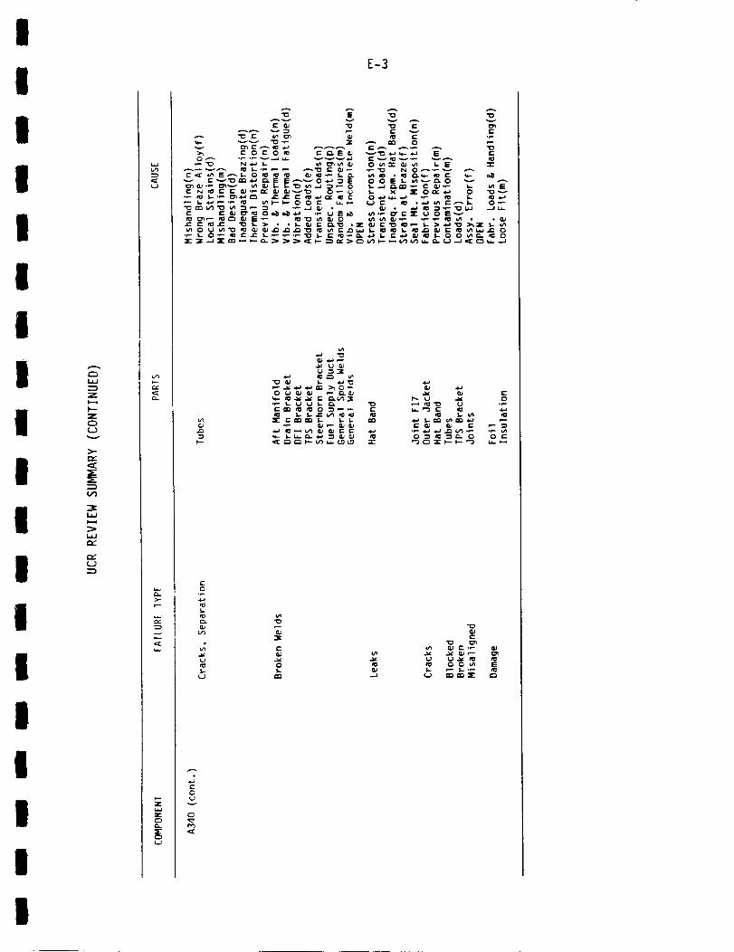
I
I
I
I
I
I
I
I
I
l
I
l
I
I
I
I
l
l
Z
I--
ZQ
U
>-
U
E-3
u
z
r_
_.a -o a.a
• P C_ P Q_ G) E G; G_ E P
E0.p
ror_
V_
ro
.._ _-"_
C:: .._ G.) £;._ G;
er_ _j _.j e_ ,_ 5r- C3
0
v
C_
¢[
I

O
I.s.J
b--Z
C_
>-CZ:
=E:
i,J
LsJ
Oc:
r_
r_
r_
>-
...J
t.s-
C1.=E
E-4
EE
l- t-OO
r-r-
EE
00_-
_*_--c_" o_'- _ c _-,--_ _ s. _ "_
0
_.o_ _- _. _.
C_ ,"
¢oI.
_" c= (U0 O_
0_"
0 ,Y
r_
i
III
IIII
II
II
II
II
III
!

I
II
iI
II
II
II
II
I
I
III
:;=
)---
Z
0U
>..
(.,')
3=
U
>-
-%..J
(:C
(:3r_:E:C_U
"_
e- r-._
• . _ _"g
E-5
u_
4-) .P 4,-) _-
.G
_'_ "; _ "__
0 c_
t_D _ r_a
um
u
C_
I

Z
F--
Z
O
L)
i,I
i,i
r_
(J
u
tY
>-f_
_E
F--z
C_
E-6
•_ ___-_ ,-_ s_._I ul •
0 (2_
i_- :3S.
_' .E
0u
r_
I
I
I
II
II
I
I
II
II
II
III

E-7
!
l
I
I
I
I
I
I
I
I
I
i
I
I
Z
I"-"
0
{,._)
,,::[
:E:
I.l,,J
I..l,J
i,",,-"
tY
(.J
u
E
_"- E _C L
W _ 0 r_
...de,..- _ e'-
,4_ G.) _ ,,-_ _ _ _ VI.b_ U _"" k,i.I ,._ _ ,._ ICI_ _ ._ t,,_.l i,,_,J_,._ ,,_ ,._ _ _e'_ ,._ _ I1_
-.e _ t..
," ._ ,- GJ _" _-_ • _.l:: _)._ 0 •
> _,
L
°p
°_
C _ E _ w .P I_
G)U
e-°p
o
I
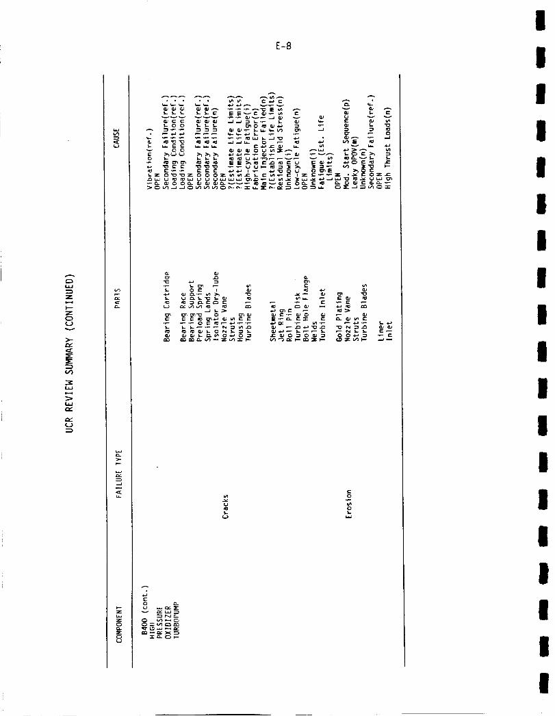
I.&J
Z
t--
c_
>-r,,-
s--=K
_>
Q_
>-
C)r_=E:0
E-8
s..
_ _ _. _._ O_-a 0 _ e" O_ 0"_ 0 _ "_ 0 04-a _ ._ e-
0 _.
en_ew
m
I
I
!I
II
II
mI
II
I
I
III!
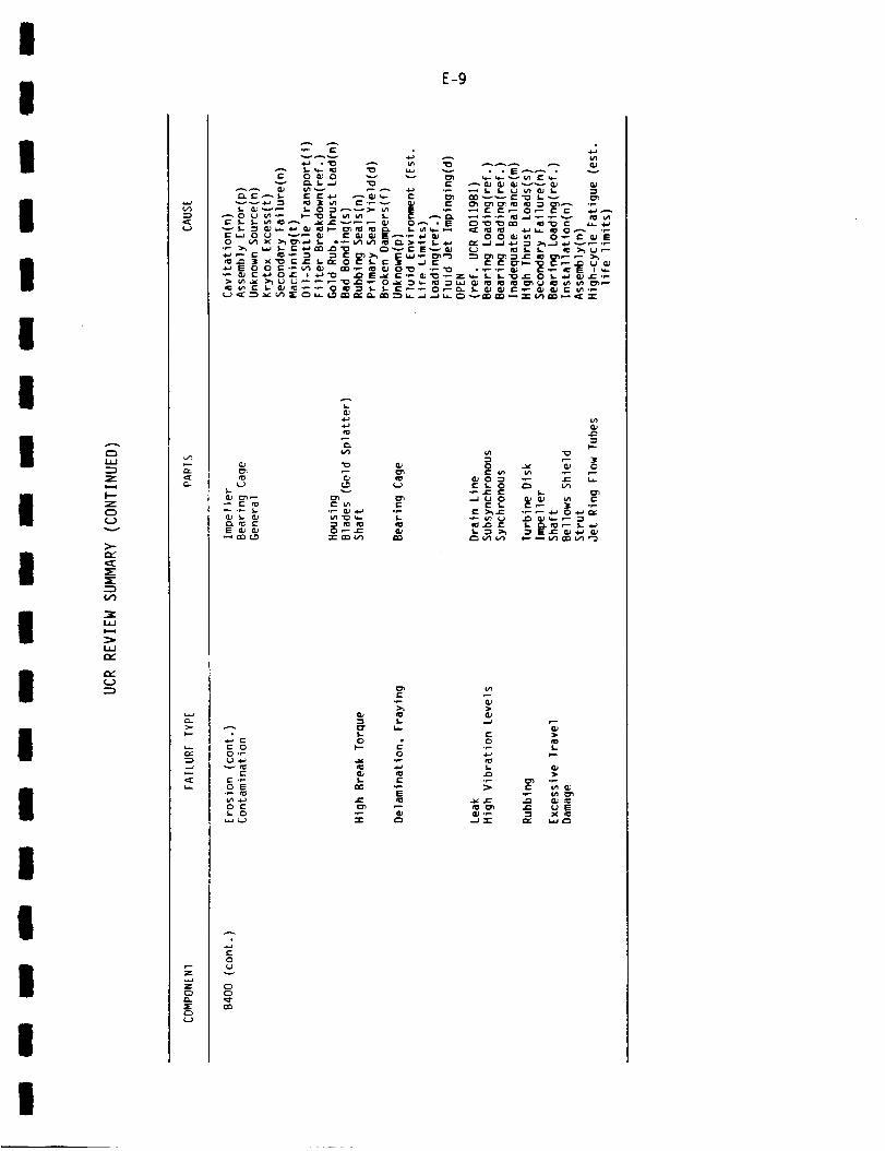
I
I
I
I
I
I
I
I
I
I
I
I
I
I
I
I
l
I
C:3
l=¢J
:Z:
I--"
Z
E)
U
>-
E
'::E
:E
:E
¢/1
I.IJ
iJ.J
E
E
U
E-9
G-
>-
,::E
r_5"C_U
.p .p _ .P .p
"P • -P "O • .P-P {1_ I=-P i_ E I q-
I..
r_ )_.
]¢0
.p
L_ _ U _ S- 0 P_ V_
_._ __ ._ ._ = ,_,- .._._ o._,,.
_E 0 _ 0EO P C .P
P
"P_ S
• "_ _ X_
_E0U
C:_C_
I
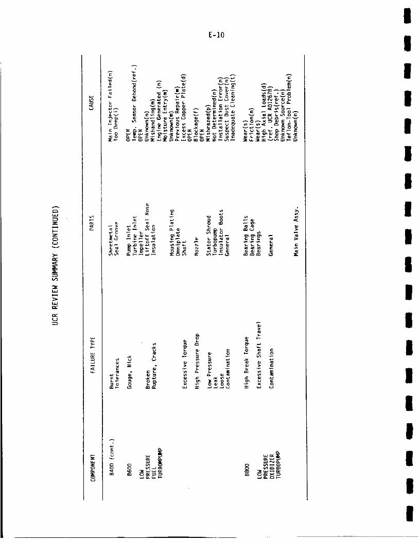
#,-.,.
ill
:D
Z
I--zc)c_)
)-c_
n_
n_(_)
I--
c_
>-I--
-J
I.-z
C_Q_
C_¢-)
E-IO
c-
"F_u..
_v",-}clI::
(.-
r- (-._ _ I= 0 v _ _..t-) .'-_w-_ _ _," _ _'1 0 _-
• 0.= _" "_ 0 0 0
Z _-
eOr_ i,-o _ _-
D 0 0 L "_ X ._ 0 _ 0 0 ._ X 0
_ _N_
I
II
III
II
II
I
II
II
lI
II
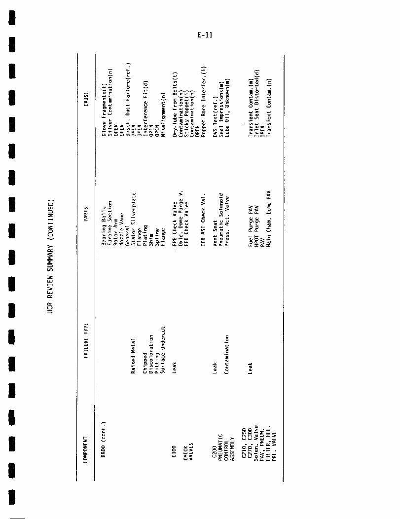
I
I
I
I
I
I
I
I
I
l
I
I
I
l
l
I
I
I
i_J
Z
z¢:)(Jv
>-p,._E=E=E
(,,'I
i.lJ
(J
c..
F--
C_
xC_
E
_._ _. "¢}
_._ _ _. "_C E _ _
E*-'
g_gg;gg'-g" .-_ OX
u
°p -_
•_ _ .- _
0u
o{3
E-II
.p
•_ lb.-
_8_8 - W.. i._ e"
f,.,._f_.
I_._
i--
_ ° _
U (3 U _ "_ ":E
Q.,...i
(.,_
(b
(,-
I=
UZ_
_._(J (_)
,p °p
_=_
=._ Ic:,_cE C)
PI"- IE:
UU O _l: _ E
I

,.--...
Z
0v
>-rv-
:[
W
,,.,.-
CZ:
(..}
(:[
>-
5"
I
E-12 "C I
I_ U •
4_
t/1
N _ N_N
Z N_O_ _ _W
I
!I
II
I
II
II
I
II
II
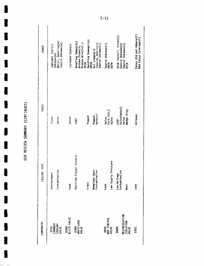
I
I
I
I
I
I
I
I
i
I
I
I
I
I
I
I
I
i
Z
I--
Z
C_
L._
L._
C_
<...}
c_
>-
.:C
I---Z
E-13
E__E
c- c-
O _ O
E _ _-
O 0_ _
S C _ 0
_._ f _ ",-" IE "_ _- 0 0
vI-0
I. e- _-
_ e- f-
0
C)
_C> C)
I. I.-
e- .,_£ e._ +._ e..o &) ,_ e_ _ ._
• _ CE _ C) I=
0 0e-¢__
2_"_ 0
_Z
>_
L
Z
_Z
0
I
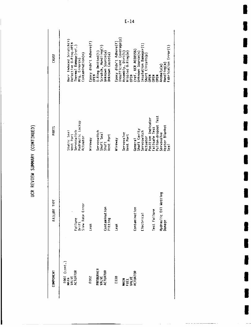
Z
I--"
Z
O
f,Jv
>..
:E:
,'-v"
r'r"
c.)
1>-I.--
z
XC)(..)
E-14
_= ,._ ,._=
U _P 5-4-) C ._ "-r- 0 _ ,.,Li
0
(,J o_0
¢..
oJ
0
.... =, -_ _ "_ ,- =, _ -=_
0L) _C
_ _ Z_
I
III
III
II
I
I
II
II
III
I
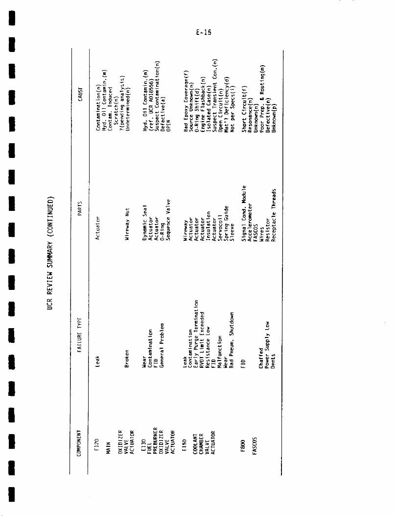
I
II
I
II
IL._
Z
I--"
I z0(_)
IL._
r',,"
I °
I
III
I
I
>.-l-.-
--j
C_
:E:C_
E
t" <--_ L.J _
z
(_ :3[
c_
I'-" CK
E-15
v
E 0 _ 0
_ (-.-) > X -'_ _ W.. "C) L _J
>
0 _ :_
_ _ _',_ g _ _ _"r. _
IE
0 ",
e-
{,,,.
o_ _ __ r e-
z_
qD e_0 _J
_r" _.
• _ I,--
_ _-_ _ _,_
0o_
"_ 0
_'_ "_ S
Z_0 C)0 _.J
I
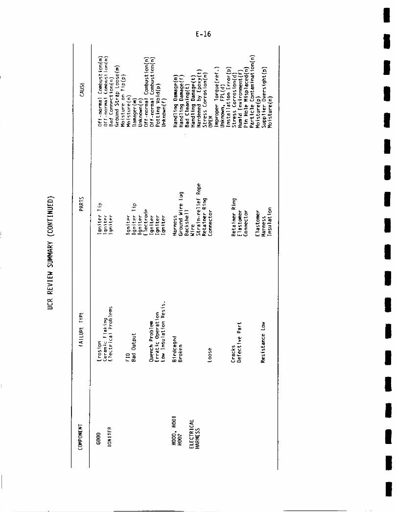
C:3
;5
H-"
Z
C3
(.J
V')
laQ
LLJ
E-16
C;,
C_
EE C C
O O E OO
E E r" --J "_ E NOO O w- O O
S,- I.- C L L I-C I. _-
e-
- °o-ooo o__ooo_ -
0cn
e- *-
"0 "e_ f,- S.- 0 S. _ 0 (i_ -_
0_
t- o
t_
g ._.;.•_ E,,_
o_
_,o0 _ O,
e_
_m
III
II
II
II
II
I
I
III
II
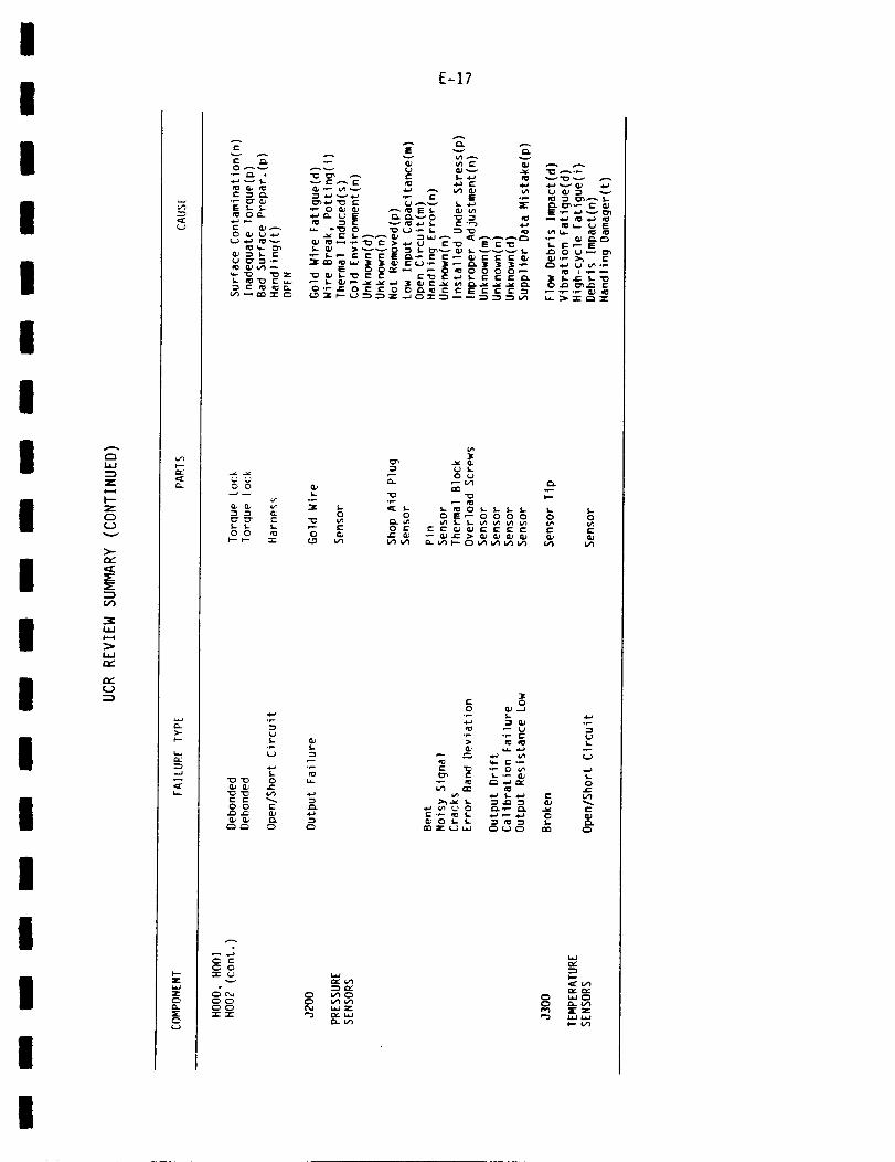
I
I
I
I
I
i
I
r_
Z
I zC3
(J
_C
(J
I
I
I
II
I
v)p-Qc
>-p-
...J
F-z
C)
C_L)
E-17
(-
('-" r_
_ Or_
u_Z} .,,,_ _ r" E
_ _.,,- _ e" > ,,_ U (-_ E r-. -_
,,= =._ --,__ _ , _,,-_., _,_,__ _ _o_,_-o_ ,'_oOn.-
U CU _
T. ,-_ _"_._._ _.,
r_ u_0 _ e- {- _ _ E i" I- l" e-
I-0
v_
c.J
0 0 E _.
3Cr 00 _--_
>
:z: cJv
C_C_C:>C_
C) V_V_cM _._Z
I,--
C, Q-¢_r,_ _rz
I
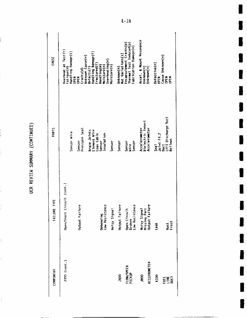
L_
Z
I--
Z
O
v
r',-"
(..)
C_{.J
E-18
E u', E"-"
_ "_._
t.._ ,_ Z'-p _ e" G_ "0 _"_ t,,', t,.. u'_
w...v _
._ (L_ 'w.*.
$..
R}r,
_" _ t" .1:: ,I: &J " C G; ,'_
gJL _ f,..
_P GJ .k_ f_ .l_ .¢-t
0
0_J
t,-
r_
t- e.,. >,, _e,,' >,_._ '-_
:} 'L
I
III
II
II
II
I
II
II
III
I
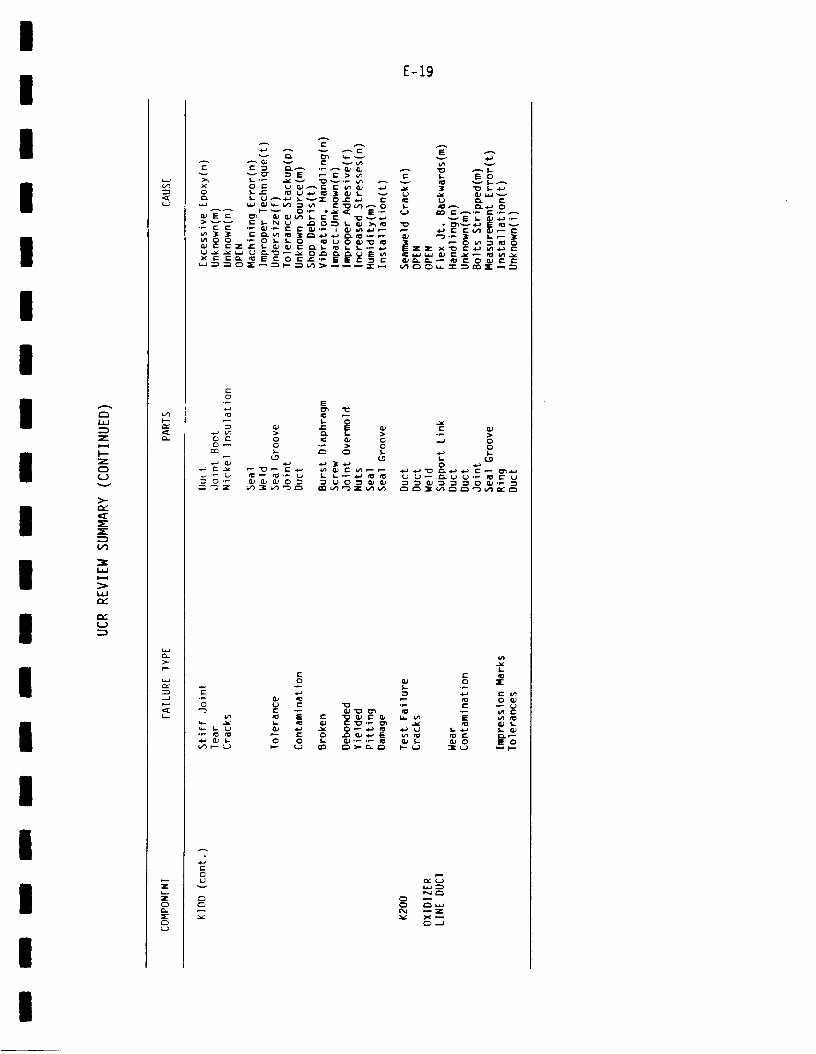
I
I
II
II
I
III
II
I
II
II
I
2:
Z
C)
v
>-
_C
L._o..-4
-.j
t.Y
_=_
r_
0
E-19
4-)
0 "--'i'_ r" _ U i:. C
c_r
r- r- (o0 _ 0
0
N_-_
e_a _Z
I
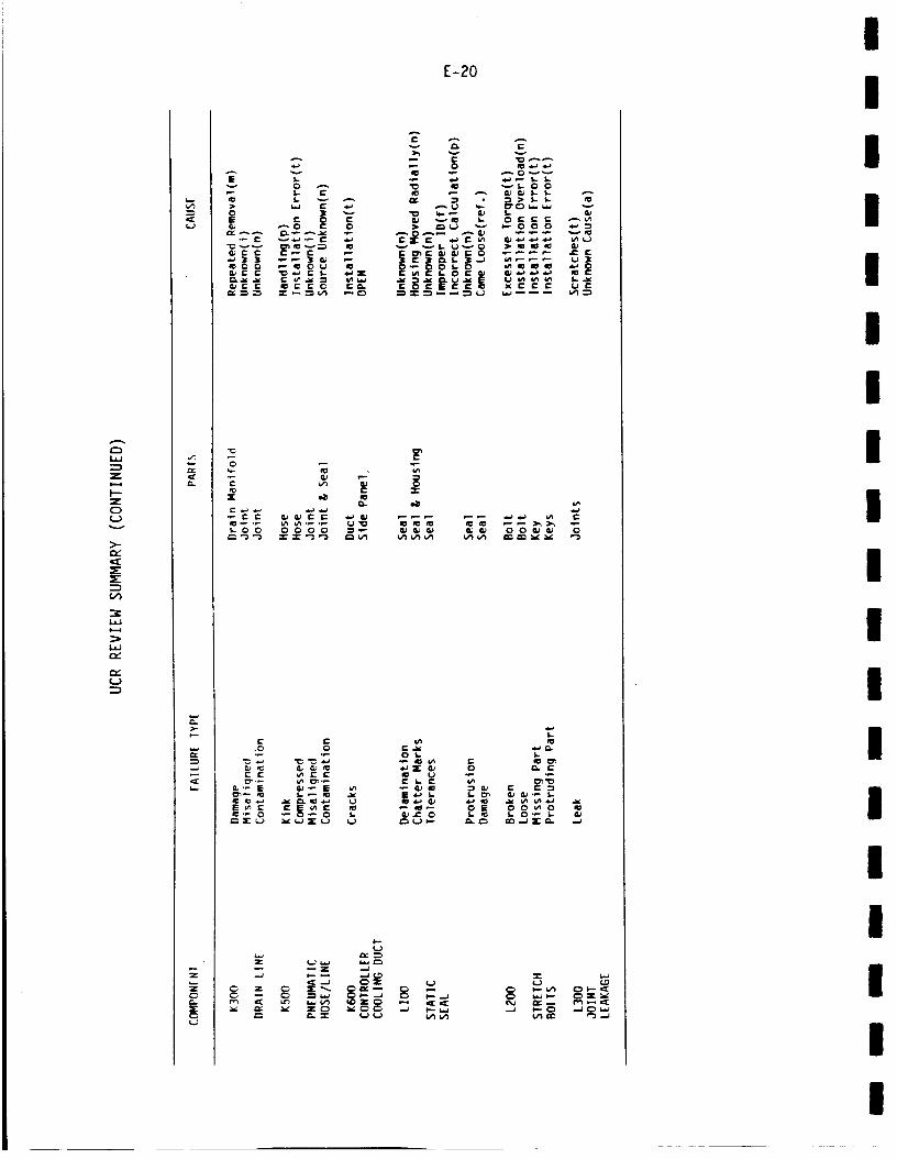
i,i
Z
I--
1,1
1,1
r_
r_
0.
L v> w r- ,_
I=
_0 G P" _ O U
r- r-
_-.J
l_ ,"1 ''r
.=d
E-20
0 I.. I..
Iz ._._ _ _ t_ _:._ _._ "_ _
-,J _'-Wt_lt_
"2"
.--_ t-- C:)U')I_
C_--_
I
III
III
I
II
II
I
II
III
I

II
I
I
II
II
II
II
II
I
II
I
C:)L._
l-'-
v
>.-
C_
f_
>-i,.-
v J¢:00
L O0
Z I_ .,_ ,__
-_ ....... _,-,
C •
o_
E-21
I

E-22
(THIS PAGE INTENTIONALLY BLANK)
III
II
II
!I
II
I
I
Ii
III
g

I
i
I
I
I
I
I
I
I
I
!
I
I
I
I
I
I
I
I
APPENDIX F
SUMMARIES OF SSME ACCIDENT/INCIDENT REPORTS
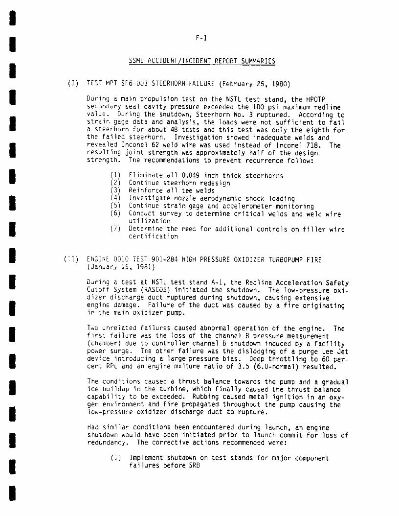
I
II
II
II
I
II
II
II
I
II
I
F-1
SSME ACCIDENT/INCIDENT REPORT SUMMARIES
(I) TEST MPT SF6-003 STEERHORN FAILURE (February 25, 1980)
('I)
During a main propulsion test on the NSTL test stand, the HPOTPsecondary seal cavity pressure exceeded the i00 psi maximum redlinevalue. During the shutdown, Steerhorn No. 3 ruptured. According tostrain gage data and analysis, the loads were not sufficient to faila steerhorn for about 48 tests and this test was only the eighth forthe failed steerhorn. Investigation showed inadequate welds andrevealed Inconel 62 weld wire was used instead of Inconel 718. Theresulting joint strength was approximately half of the designstrength. The recommendations to prevent recurrence follow:
(I) Eliminate all 0.049 inch thick steerhorns(2) Continue steerhorn redesign(3) Reinforce all tee welds(4) Investigate nozzle aerodynamic shock loading(5) Continue strain gage and accelerometer monitoring(6) Conduct survey to determine critical welds and weld wire
utilization(7) Determine the need for additional controls on filler wire
certification
ENGINE 0010 TEST 901-284 HIGH PRESSURE OXIDIZER TURBOPUMP FIRE(January 15, 1981)
During a test at NSTL test stand A-l, the Redline Acceleration SafetyCutoff System (RASCOS) initiated the shutdown. The low-pressure oxi-dizer discharge duct ruptured during shutdown, causing extensiveengine damage. Failure of the duct was caused by a fire originatingin the main oxidizer pump.
Two unrelated failures caused abnormal operation of the engine. Thefirst failure was the loss of the channel B pressure measurement(chamber) due to controller channel B shutdown induced by a facilitypower surge. The other failure was the dislodging of a purge Lee Jetdevice introducing a large pressure bias. Deep throttling to 60 per-cent RPL and an engine mxiture ratio of 3.5 (6.0-normal) resulted.
The conditions caused a thrust balance towards the pump and a gradualice buildup in the turbine, which finally caused the thrust balance
capability to be exceeded. Rubbing caused metal ignition in an oxy-
gen environment and fire propagated throughout the pump causing thelow-pressure oxidizer discharge duct to rupture.
Had similar conditions been encountered during launch, an engineshutdown would have been initiated prior to launch commit for loss ofredundancy. The corrective actions recommended were:
(I) Implement shutdown on test stands for major componentfailures before SRB
!

(III)
(IV)
F-2
(2) Incorporate additional main chamber pressure reasonable-ness checks in the software during start transients toensure redundancy
(3) Delete the low main chamber pressure redline and add lowerHPOTP turbine discharge temperature redline to check forpossible icing
(4) Modify Lee Jet orifice retention method(5) Perform a pull test on all Lee Jet body installations(6) Stud), to assess engine control and redline logic for
vulnerability(7) Study to assess all other Lee Jet installations in SSME(8) Study of HPOTP turbine end clearances(9) Inspect all facility Invertron units10) Replace all facility Invertron unit power transistors
ENGINE 0009, TEST 901-307: ENGINE 0204, TEST 902-244 FUEL PREBURNERFAILURES (December 22, 1981)
Failures were in the LOX post injection elements caused by high-cyclefatigue. The mechanism for high alternating stress is the combinedmainstage mechanical vibration and the element hydrogen flow inducedvibration. Also, in engine 0204, the injector face plate was erodedand slag buildup was found on forty posts.
The design fix was to increase the moment of inertia and damping inthe cantilevered LOX posts. This would reduce peak alternatingstresses below the endurance limit. The fix incorporated three pinsupports between the LOX posts and the fuel sleeve to restrict themotion.
POWEREDUI,IT 2015 PROOF TEST FAILURE: FUEL PREBURNER-FUEL SUPPLYDUCT
The fuel preburner fuel supply duct ruptured during the powerheadproof pressure test. A hardness test performed on the duct found itto be low of the designed hardness. The supplier failed to heattreat the elbow because of a misunderstanding of Rocketdyne drawingrequirements. Also, Rocketdyne receiving inspection failed to detectthe omission of heat treatment. Recurrence control consisted of:
(1) The planning at the supplier incorporates heat treatment
(2) Future supplier planning for small suppliers will be
reviewed by Rocketdyne personnel
(3) Receiving inspection plans have been revised to incorpor-ate physical verification of heat treatment for all appro-
priate parts
(4) Previously accepted parts requiring heat treatment thatwere accepted by the same individual at prescreening have
been checked for compliance
(5) Personnel responsible for prescreening have been advisedof the requirements at a workshop
II
III
II
II
II
I
I
II
III
i

I
I
I
I
I
I
I
I
I
I
I
I
I
I
I
I
I
i
(V
(VI
(Vll
F-3
ENGINE 2013 NSTL TEST 901-364 HIGH-PRESSURE FUEL TURBOPUMP KAISER HATFAILURE (July 14, 1982)
A scheduled 500 second full power level mission simulation test wasterminated at 392.16 seconds due to the preburner pump radial accel-erometer redline. Major portions of the engine were severed from thetest stand attachments. Using various data, analyses, motion pic-tures, test fire simulations, and model simulations, it was concluded
that the recently redesigned HPFTP Kaiser hat provided a hot-gas leakpath of hot gas into the bearing coolant. Turbine bearing failurewas followed by rotor displacement, turbine blade failure, rotor
seizure, rupture of the HPFTP inlet, and an oxidizer rich shutdown.
This was the first test of the latest redesign of the Kaiser hatassembly. Recommendations were:
(i) Return to the old Kaiser hat assembly configuration(2) Periodic inspection of the Coolie hat nut for retention
Adoitional actions to prevent other recognized potential failures:
(I) Reduce turbine operating temperature(2) Improve HPFTP Liftoff seal dimensional control(3) Improve Kaiser hat inlet design with a seal(4) Improve fuel preburner propellant distribution by cooling
ASI core
ENGIr_E 0107, SSFL TEST 750-168 OXIDIZER PREBURNER OXIDIZER VALVE BALLSEAL FAILURE (January 27, 1983)
A scheduled 300 second test was terminated normally, but subsequentdata anal)ses showed the HPOTP discharge temperature rising signifi-cantly beginning two seconds after shutdown command until the temper-ature sensors failed. No external damage ws apparent, but signifi-cant high-mixture erosion was found in the HPOTP turbine area andnot-gas manifold. A leaking oxidizer preburner valve was found to bethe source of the high-mixture ratio. The ball seal had circumferen-tial erosion and a radial seal crack was found. The cause was a
fuel-rich ASI hot-gas backflow into the valve seal cavity duringShutdown.
Corrective action was recommended to preclude hot-gas backflow duringshutdown. Until an adequate solution is established, the OPOV sealtest life should be limited to ensure seal damage does not approachproportions experienced in this incident.
HE;T EXCHANGER COIL ARC BURN (July 25, 1983)
During the tungsten inert gas (TIG) weld operation that joins atransfer tube to the heat exchanger liner the welder made inadvertentcontact to the heat exchanger coil producing an arc burn. This inci-dent was the result of the welder being unable to see the weld jointfor about 1.5 inches of arc length. The welder removed the protec-tive closure around the heat exchanger coil to weld past the point of
i
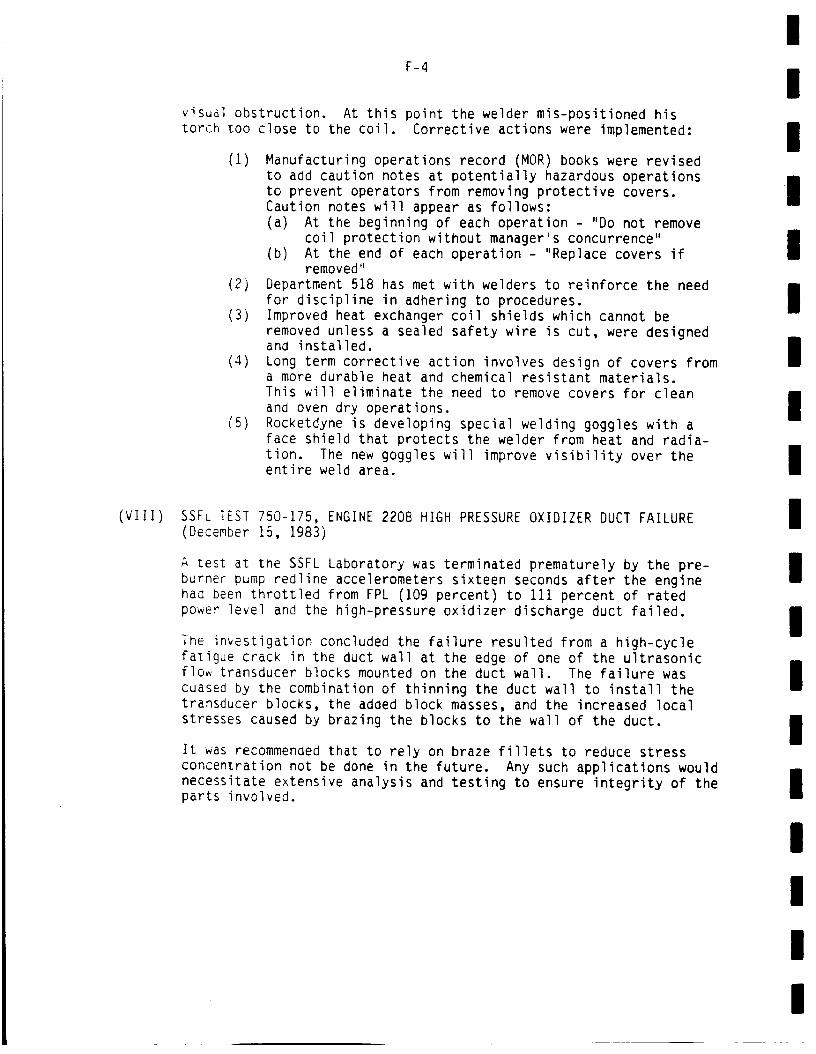
(VIII)
F-4
visual obstruction. At this point the welder mis-positioned historch too close to the coil. Corrective actions were implemented:
(i) Manufacturing operations record (MOR) books were revisedto add caution notes at potentially hazardous operationsto prevent operators from removing protective covers.Caution notes will appear as follows:(a) At the beginning of each operation - "Do not remove
coil protection without manager's concurrence"(b) At the end of each operation - "Replace covers if
removed"2) Department 518 has met with welders to reinforce the need
for discipline in adhering to procedures.3) Improved heat exchanger coil shields which cannot be
removed unless a sealed safety wire is cut, were designedand installed.
4) Long term corrective action involves design of covers froma more durable heat and chemical resistant materials.This will eliminate the need to remove covers for cleanand oven dry operations.
5) Rocketdyne is developing special welding goggles with aface shield that protects the welder from heat and radia-tion. The new goggles will improve visibility over theentire weld area.
SSFL TEST 750-175, ENGINE 2208 HIGH PRESSURE OXIDIZER DUCT FAILURE(December 15, 1983)
A test at tne SSFL Laboratory was terminated prematurely by the pre-burner pump redline accelerometers sixteen seconds after the enginehad been throttled from FPL (109 percent) to 111 percent of ratedpower level and the high-pressure oxidizer discharge duct failed.
The investigation concluded the failure resulted from a high-cyclefatigue crack in the duct wall at the edge of one of the ultrasonicflow transducer blocks mounted on the duct wall. The failure wascuased by the combination of thinning the duct wall to install thetransducer blocks, the added block masses, and the increased localstresses caused by brazing the blocks to the wall of the duct.
It was recommended that to rely on braze fillets to reduce stressconcentration not be done in the future. Any such applications wouldnecessitate extensive analysis and testing to ensure integrity of theparts involved.
III
I
I
II
II
II
I
II
I
III

i
I
I
I
I
I
I
I
I
I
I
I
I
I
i
I
I
I
I
APPENDIX G
SSME FAULT TREE DIAGRAMS BY COMPONENT
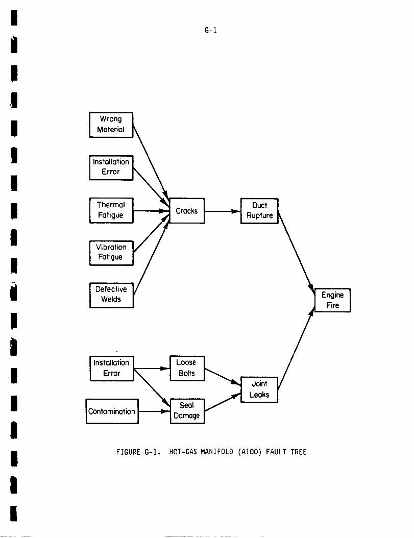
I
I
!
I
FIGURE G-I. HOT-GAS MANIFOLD (AIO0) FAULT TREE
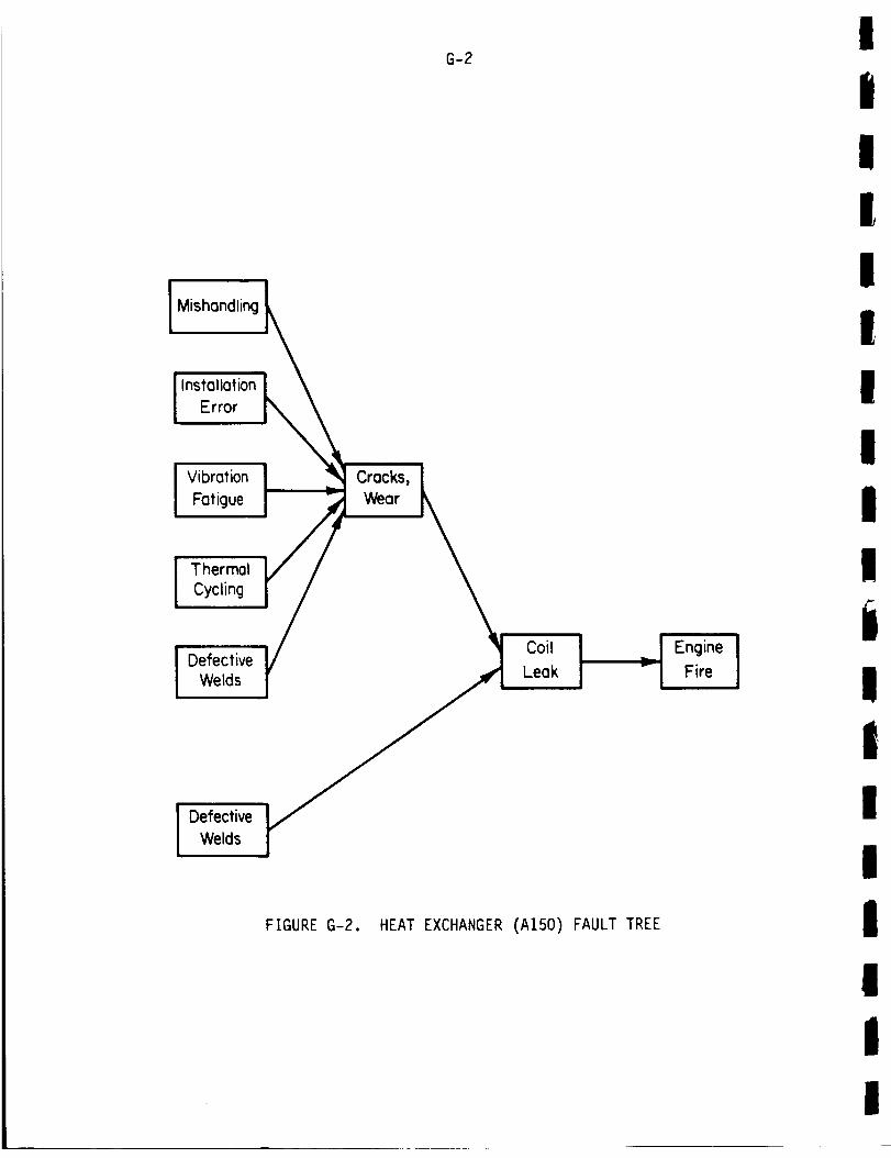
i Mishandling
InstallationError
VibrationFatigue
I ThermalCycling
I DefectiveWelds
Defective
Welds
Cracks,Wear
FIGURE G-2.
G-2
Coil ILeak
HEAT EXCHANGER (A150) FAULT TREE
It
II
i
II
II
Ii
I"- Fire I
!!!I!!I
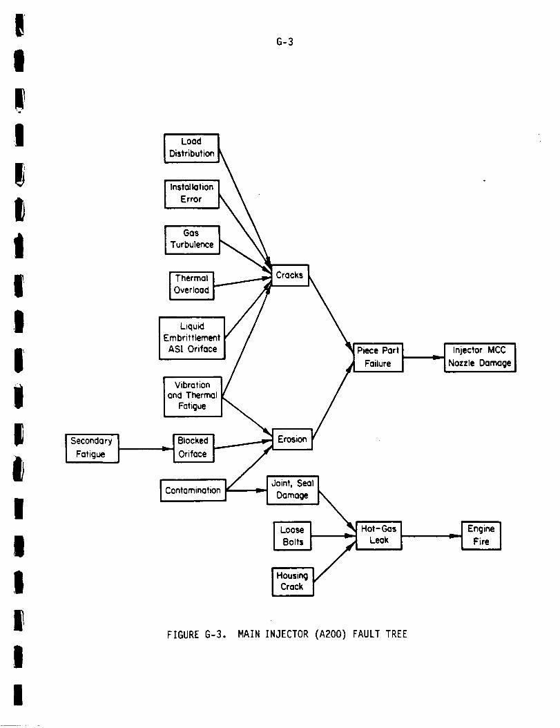
_
I
!I
tiIi1il
I
IIf
,|
Secondary
FatigueI
LoadDistribution
! InstallQtionError L
I GasTurbulence K
ThermalOverload
I LiquidEmbrittlementAST Orifoce
Vibrationand Thermal
Fatigue
Blocked
Orifoce
IContamination
FIGURE G-3.
G-3
Part JjFailure
Joint, Seal 1
Damage [_
I L°°se I _J
I BoltsI/IHo=_1/
Hot-Gas ILeak
MAIN INJECTOR (A200) FAULT TREE
Jl Injector MCC JNozzle Damage
_ ! Engine I
I Fire J
I

G-4
Hot-Gas Wall
Center line Crack
LinearOelamination
Erosion
MCC Wall
Failure
InstallationError
IBad Weld
Hot- Gas
Joint Leak
MCC L
Burn Thru I_
I
[,n_,a,,o,ion_l Error
Coolant
Manifold
Leak
FIGURE G-4. MAIN COMBUSTION CHAMBER
Possible
EngineFire
_._ Fuel in Aft
Compartment !
(A330) FAULT TREE
,!I!II
IiIIi1II
II
II
I

I
!! I: o_I
i i///iI \%%
," /! ,1 /I
" __1
| -
! 7-
G-5
%
%\
oEo
NN
, !I I 1
iii
I..i.I
I--._I
I.I-
o
)-._Jnm
l.IJ
i.a.i
N
N
z
I
W
.-j
I,
I
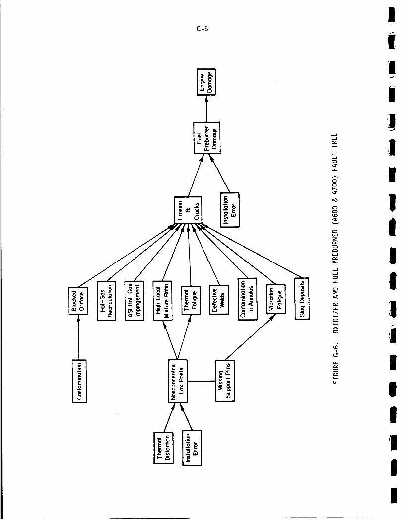
l
G-6
iL_W
.J
_C
C_Or_
c_
OC_
Zr,-
W
.-JW
N
XO
I(-_
r,-
L_-
I!!
.i
I!II!II
i
IIIII
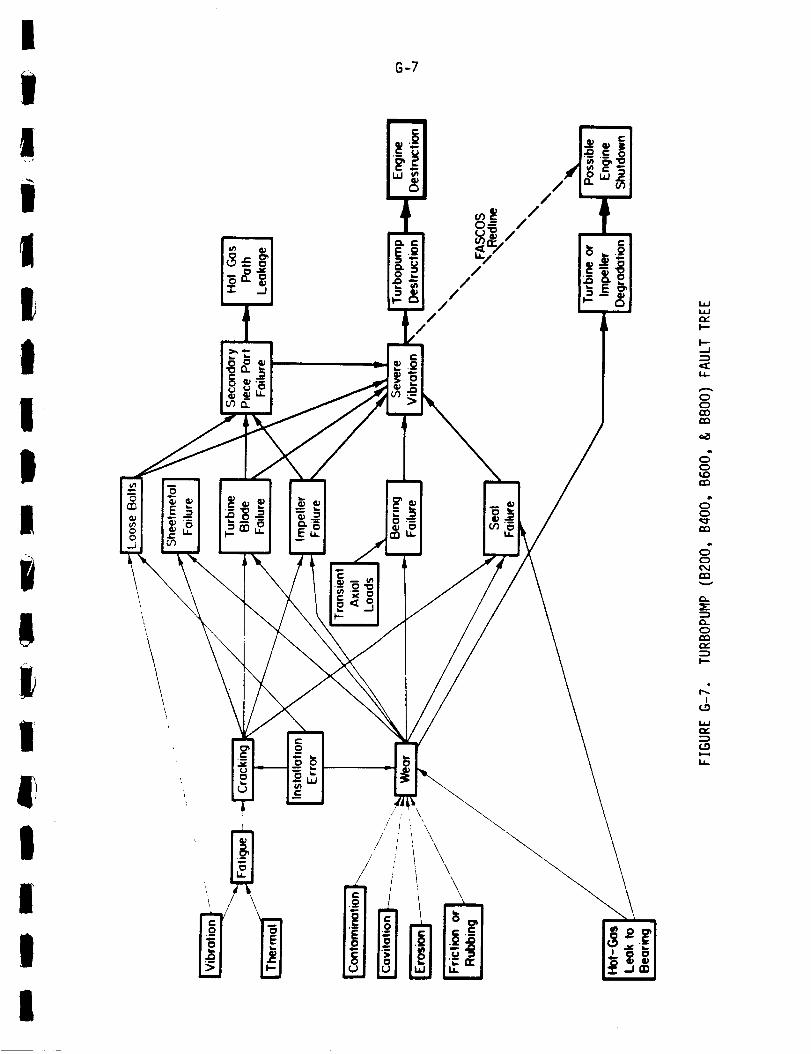
I
i8-7
!t
/
o_ /_ /
!I
|!ii
1IIII
\
\
//
//
//
n
IJ=/
.-vIn
o0QO
d_o
do
d
e_
I.-.
!
iY
ii
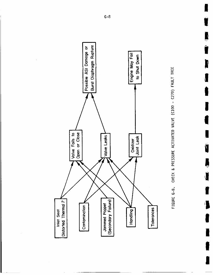
!G-8 j
II
_1._ .=--_
0,.. 0:) ..-,.. Io
/, 1
N
•_ |
!!
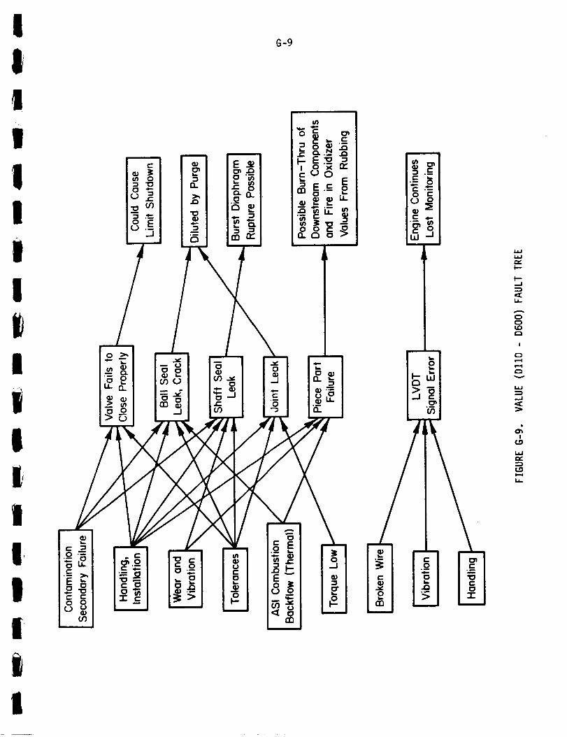
G-9
!, i
!.- vl II- i_ ",: I::: -- I I I _'_ r_' _ .c_"_
,, ! °LI I o'-._ g'E
,,,_ "-"I I'_ C. . ¢: ,0_
I ° ' _1_m
/'iI
, /i
i ¢j) __. :|
I--
I---_J
0
I
0
,.J
I
W
|!
(THIS PAGE
G-IO
INTENTIONALLY BLANK)
,
!I
!
II!I
!
!!i!
I!I
!
!
!
!!
!!
!!
!
!
!,
!!
iI
APPENDIX H
SUMMARY OF SSME TEST FIRING CUTOFF DATA
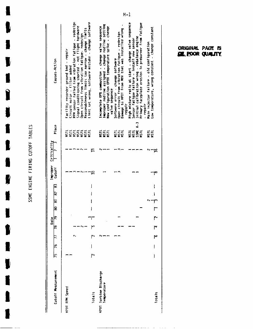
I H-1
!I!
!i
ii1
It
!I
|
!I
II1|
C_
I,
l'--
(.9Zw-i
I,
W
Z
(..9Z
0
1
I1=
&.
I-
0 0
E_--_
c_CO
C_CO
r...
|q_
0
• P G_ ID
_ _- _; _=
_zZ ZZZ
(I,)w _ o
I tJ :_
C 0 O" IO
"__ _ _"
: U
I
1
I
I
"-r-
1=. w
c_
c_-r
C_L
J=_J
C:>G-
I
I
r-
r'
i
ORIGINAL PAGE P3
iGl,,.L'ooe Qu,_Zl_.

H-2m_
0
(./')
i
I---
L_
C_
l---
,-v
i,
Z
Z
i,i
=E
(./')
t--o
m.J
i
-.s
m.-l__..),
0 O
E,-_
C
r_
E
vl
X
0
+.o++_ .:•_._ I _ I_ _ _ * <1_
_ f,'- "_ O_ J_: _ "
Z Z_ ZZ Z Z Z Z Z Z _ _Z
_ I_
-1-
I
p-
I
I
I
t--
.1=
g ,
•_ _._
e. e- o
e-
,_1 ZQ_
t_ I.,,_ v*)z ZZ
t
I
I
I
I
I
e-
t1:s.
s..
s '_
G.
!I
II
|iIItIti!I!1I1

i
IIII
IiI
tt!II!I1IIII
-,Q
G_
°r,,,,,
t-
O
(,_
r,-,,
I'--
L__
(_',9Z
r,,,"
Z
t,,-.-4
Z
I,J.J
L,_
r'.=)
,,J,,J
,:[t
aP
I.-
0 0S.. _-)
E.-)
ZZZ ZZ Z Z
,.-* f_ (_l ,-._ I P_
"i - "1
C
H-3
0
[:
r_0
e-
,1= o
t_ _- _-- Vt IO
Z
I
0
0
xw
Z Z _Z_Z Z
...... I_ _1 _
..... I_ _1 _
_ _ I _
"_c_.
OJ-_
G.
S-
I..¢_.
S- eL)
e- S.-
0 S.-'_ 0
C_
'-r"
ORIGINAL P_C_
OF POOR (_L_ALITY

-i
"0
8J
"-sl--
0
l/'lW
....I
I--
0
I"-
Z
Zi,.-,t
Z
c0
I
ll.
0 C
_'_
i=
vI
5"-
0
i. r.8,1 -_ Ci.
0t I,-
,l= I.- 0
_ I,.,i 0
H-4
ZZ 2: "J"ZZZZ'_-J" Z Z='ZZZ
r_
0_
I
0
I.
i.I
_Y0
c0
c
i 0I.
_E
c _
z7
_ ,..,I_
ex
I
!
!I
!iIiiIII'
IIIlII

II!Ii1l!il
l
I
I
lJ
Iii!
E
P
.J

H-6 I
Q)
(.--
.p..
4-)
E
OL)
(..,q
LIJ
_J
I'-
Ll-
ii
C::)
(-3
(-9
Z
L,I..
L.I.J
Z
Z
l=l.l
l=lJ
=E
r.F)
£:O
_Ci
u
L..)
o..
0 0
E_J
toP_
r,_
E
I.
0
U
Z _ _ Z Z
I-
t
r"
E
s.
u
.4=
,.,r
¢..
u
O)5- I
OJ
_- 0
E .,._ r-
E _
"1 -
e- N__ 0
P OJ _l_J I.- P
IIII
Ii1iI
i1
I
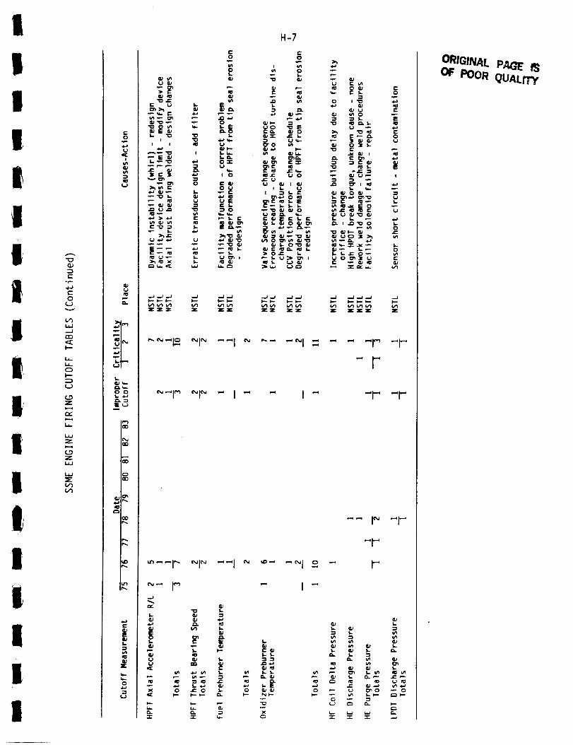
I
II
I
iiIiiI,
Ii
I!I
IuI
°p-
C"
O
.--J
C_
h--
U-
O
-=_
Z
s===_
L,,
Z
Z
C_
¢-O
i
¢+5.=s
¢V
P-i
.t.-i
I_=-O OS..b._
P_
E
CVZ
H-7
_ _ _ _Z ZZ Z
_J _J ..J
ZZ:_
_'_-I_. _1_ --I _ "-" "_1 -- - "
_-I _ _1_ -I- " I-
_--I _ _i _ --I _ _"
¢_ _ I (_
.J
r-- S. t" S: (U(IJ (0 S- S.CJ G) S- =}
• _ ._ 1-_._ a_ _ _-E
..p.
1- &;
S- G; 1-
e,.o
r.
t-O
!
1.
0
r-
Z
1.
1.
1.
ORIGINAL PAGE' F3OF POOR qUALiTY

H-8I
"0
c-
0
(-2v
I.iJ
-J
I---
LI-
0
k-"
Z
0
I
U
0,.
0 0
EU
"_ I
CO
E
0
i_ 3 u -,o
S.. U I=
I-- I...- _--
_[_zz Z ZZZ
(_
"0 U =1 P(1_ I,- I- I_ P
(I) S,- _ C_,._ _
I_ _,_ S.- _ e- _l Ill...l.a I_.'_" I _ e-
_" , i.. I _
S.- *_ 0 I,..
_ _.. _, _ -_ S..
:I[Z: _: _:(/1 Z Z
_'-'I _ "1- "''1 _ ~_l _ "_1 _ "1 - _l _
-'1 _ -I- "--I _ -_1 _ _1_ -I -
•- ...i _
C
S-
OI;. _
U
I- S..
J= P JEP i_
| =0 0
C
E:_ 0=E _"
II
I
iiI
iIiII
IIi

III
I!It
iIIiiII
ni
I'
p
II
Ii
II
"I
(,...
.p
0U
I.i.J.._1
<E
La-
U-
0
F--
Z
La-
Z
CO
LaJ
3
o_ i
0 0s. _a
S..._
¢"_1
i
I
i
I
r-a,)E
S-
!"
0
"I
C
t-O
0 uO.
3e ,_-
m _U
C _U
f- t'-U
O _n
S- I-O
I. U
E
O.P
zz
,-_ ,--.I_
C O
-'r-
H-9
I
_n I- I.
t- I N (_.1 .1_ _.
_ _; _ _- _ ._ £3.a- i_I,.-.-_.p e- I ,'--
O
O _" E "_ C _-
,e-
• _ _ I= _ 0
0 eX V'I X 0 I= I_ C
I
EOI.e_
e,-
O
e-l,.
OU J=
I _ 0
C_ u-
zZZZ _ zz Z _ z
"_ ..... I _ ~1" "l- -I"
"'1 " ~1 -
S.
S.
U
0U
"1-
L
t-- ,_
J= m IE
O I- O O _-) O
C "-r-._
U _ ¢.-)U _ (..)
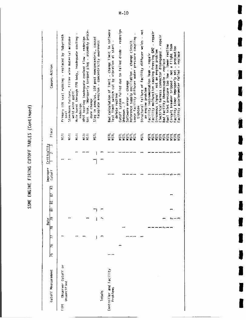
H-IO
Q.)
r
ore.-
c-
0
l.iJ,--I
l"--
u_
0
I---
(..0
ZI-.-4
I,
i.,
Z
l.O
Z
I.,I.I
LI_J
i+q
0
O_
+0LJ
e-_ +.,_0 0
E _ _ E
"0 O+ _" 0 I _,OJ ._ GJ _ OJ_
_'0 0 t'"
= . + g _'
, ,-._- _,-_
I-0
0
e-
E ._ "_
l.J .,1_
o_
LI..
"=E0.)
+E0
!I
I
l
IIi
I
i
I
!
i
I
I
II
i
I

I H-11
I
i
II
i|
I
II!
tt
!ai
I
iI
r'-
.r-.
c-
O
I'"-
O
t---
Z
,-,,.,,t-.-4
W
Z
Z
I
,,.-4
S-
_._-O Oi.-
EJ
f13
I-
nPa;
O
!
_- E{_._-
Q; _ 0S- _ I_-_
_ _ S
_ ' ,_,
1.1,_ 0 I,- _J_J
L.
I-
_ C
0 D
._ _. _: _ _ I::
_I 0 "_ _ _:I
_ I_--__'_" e- I,- I_.O
_o_
>_
rI ._,.
OI,_,.. _._
_E
_-- 5.oe_I.
0
I=
I"
IO_
I=
0I--

H-12
(THIS PAGE INTENTIONALLY BLANK)
I
IIII
1IIIi,,|
I
IIiII
1I

!
!!!
!
!!I!!
!
!
II!
I
II
II
APPENDIX I
FAILURE MODE RANKING
Description of Procedure and Summary of Results
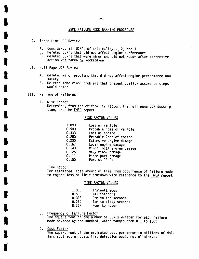
!
IIi
lI
IIli
I
III.
I-1
SSME FAILURE MODE RANKING PROCEDURE
I. Three Line UCR Review
A. Considered all UCR's of criticality 1, 2, and 3
B. Deleted UCR's that did not affect engine performanceC. Deletec UCR's that were minor and did not recur after corrective
action was taken by Rocketdyne
II. Full Page UCR Review
A. Deleted minor problems that did not affect engine performance andsafety
B. Deleted some minor problems that present quality assurance stepswould catch
Ranking of Failures
A. Risk Factor
Determine, from the criticality factor, the full page UCR descrip-tion, and the FME____AAreport
RISK FACTOR VALUES
I
I
I
a
I
B.
1.000O. 500
0.333
0.250
0.200
0.1670.143
0.1250.111
O.100
Loss of vehicle
Probable loss of vehicle
Loss of engine
Probable loss of engine
Extensive engine damage
Local engine damageMinor local engine damage
Very minor damagePiece part damagePart still OK
Time Factor
The estimated least amount of time from occurrence of failure mode
to engine loss or limit shutdown with reference to the FMEA report
TIME FACTOR VALUES
I
I
I
i
C.
Do
1.000
0.5000.333
0.2500.167
Instantaneous
Milliseconds
One to ten seconds
Ten to sixty secondsHour to never
Frequency of Failure FactorThe square root of the number of UCR's written for each failure
mode divided by one-hundred, which ranged from 0.1 to 1.02
Cost Factor
The square root of the estimated cost per annum in millions of dol-lars subtracting costs that detection would not eliminate.
!
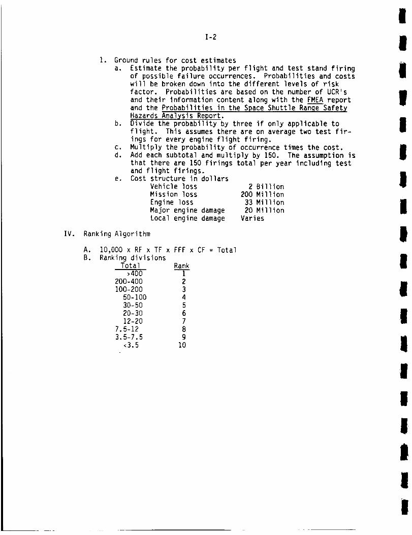
I-2
. Ground rules for cost estimatesa. Estimate the probability per flight and test stand firing
of possible failure occurrences. Probabilities and costswill be broken down into the different levels of riskfactor. Probabilities are based on the number of UCR'sand their information content along with the FMEA reportand the Probabilities in the Space Shuttle Ranqe Safet XHazards Analysis Report.
b. Divide the probability by three if only applicable toflight. This assumes there are on average two test fir-ings for every engine flight firing.
c. Multiply the probability of occurrence times the cost.d. Add each subtotal and multiply by 150. The assumption is
that there are 150 firings total per year including testand flight firings.
e. Cost structure in dollarsVehicle loss 2 BillionMission loss 200 Million
Engine loss 33 MillionMajor engine damage 20 MillionLocal engine damage Varies
IV. Ranking Algorithm
a.
B.10,000 x RF x TF x FFF x CF = Total
Ranking divisionsTotal Rank
>400 i200-400 2100-200 3
50-100 430-50 520-30 612-20 7
7.5-12 83.5-7.5 9
<3.5 I0
!
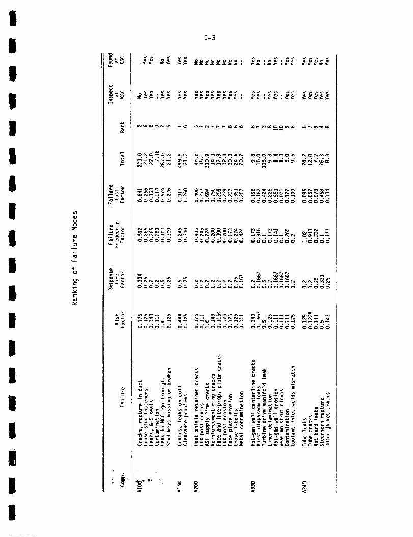
!
!
!
Il
l!!!l
I
!
II
i
i
|
!
OJ
0
aJ
::3e---
or--
LJ-
0
C
0r--
c-
e-N
_. s_ _-
C 0
S-
°
,_ o_
.,,_o°
I-3
_ _ O0000000 I_'_" Z:IC Z 3_ZZ Z 3[ I
_o o_ _ _o__Z_
00 ,,°*°°*,, ,**.,,,, *****
,*°*_*,, °°,*0
• ,,,o.,. ,.,.,
°, °,.,,,°.,
.. ,,,,,,..,
_._'_
°..°..,, ,o..o
(.1
s-
I

"O(I)
::3
t-
4-J(-
O
(,'I
(I)
"OO
aJ
-I
,r-.
q--
O
(-,r-
c _.J
l-
.'_ou
2_2
>_
OE_._
u.
I-4
>- >- >.. >.- ).. >-o ozz
>..>- ;:,->.-
_oo=o_=o_,,,,>.> >- :ooo=o: ,,,,..=
>->->->->->->->-
L
°_
•"_ _0 00 EX
._ ._ ._ .__ . . .
o
_=_-3_'_'_.._
0
Q_
ORIGINAl. PAGE IS
II
I
i!
IIItI
II
iI
II
|
II
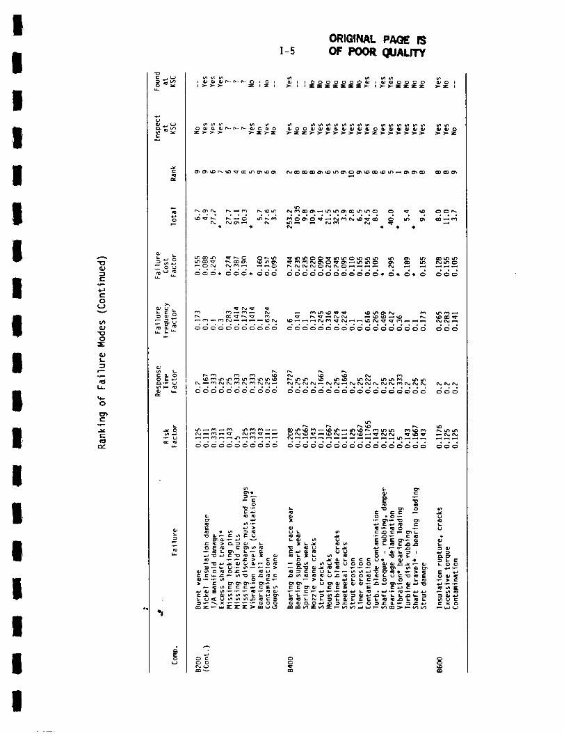
I
l
Ii
III
II
II
II
I
III
Q)
=3£:
°....
4.)
t-
O
¢....)
(,'I
(U
0
a.)
rB
U_
0
D')(.-
°r=.
c--
rv.
fo
to
Ca f,.._"_ 0
n_ c-J n:__.. U-
Q.I 0
L-- _ 00 S .,--_
u_
la.
E0
,',-,-,-_ ...... o ,'=°
° ° ° , , ° •
_c_c_c'_c_
0
r-a.a
0 0
I-5ORIGINAL P/M_ I_
OF POOR QUALITY
• 0°°o,°°°°°, • • °,o
c;c_c_
0 0
r_ r_
I
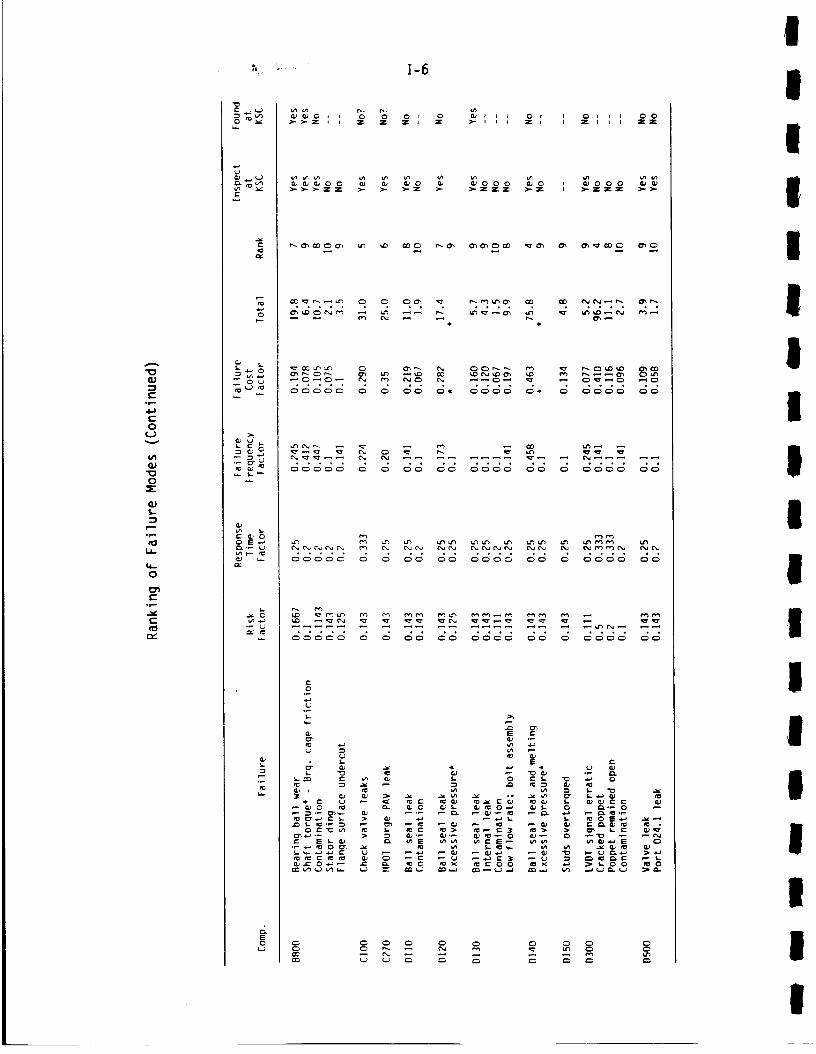
"0
(...
°e--
0
f_Jv
U'I
"0
0
S-
::3
-r--
&J..
'W.-
0
C
I-6
_'_v(-
o_c
ro
_ ou
_ a. G
_.2-_Q) u.
u..
E
_,o , , % % o , o _,, ,_-_-= , , = z =, = >-,, I 70: ,, =o,,, : o=o
_.=_ _ _ _o _ _ooo _o _,ooo _z >.- ).-z >-
.° ...... ° ° .,,, . ,.., ,.
_o _ _ _ _ _ _ _ _°___
Q
'.- ._
,_
It
Ii
I
I

I
i
I!I
III
II
II
I
II
II
I
¢IJ
-'s
°p-
c-
O
v
0
-r-
IJ..
0
_ _ 0
E0
o * o
I-7
i >- >,.
ORIGINAL PA_ iS
OF POOR QUALrTY
o>.7 >- of
....,.
O0 000000_ 0000_0 O0 _ _0_
KK KKKKKKKKKKKKKK KK KKK KKKKKK KK
• _ '_;_* °'_'_'_ _" '_._ _.._ _: .'i
C _ _ 0 0 00 0 0 0 0 0
I
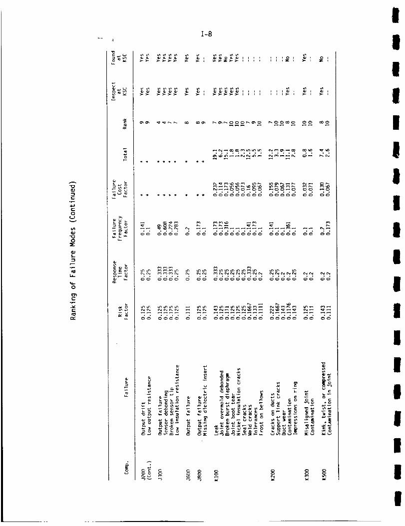
I-8
"0
a.)
_3c"
0r-
t-
O
C.J
¢1)
"0
0
_E
OJ
._.....
0
-r,-
f.,,.
u,_
-Ze_
_ 0 L_
_ _ o
u.. L _
e- Qj o
e_.P _j
u-
u_
E
>->- _-- >.- >-- >- >.- )- _.- >- z >- >-
>- >- >-
- _ _ _ _ _ _
_ C _ C_ C_ ¢3 C_ C3
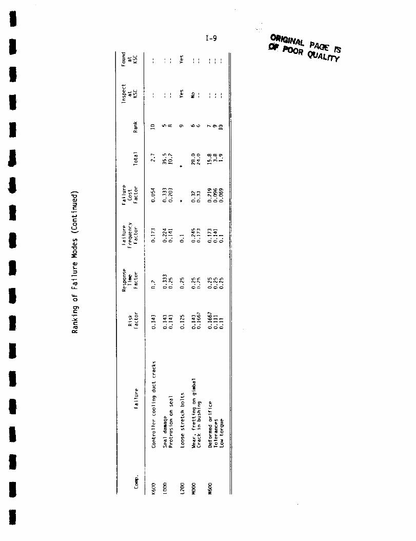
I
i
I
I
I
lI
I
I
I
I
I
I
I
I
I
I
I
°p.-
r
0
v
0
(IJ
:3
o_...
0
C
o_...
v
rO
t0
-_._o
_Ou
I-
Eo
I-9
• o° 0° 00o
• ° ° o
°
a.a ._a 3 k
!

q
1-10
Final Ranking of Failure Modes
!
!
!Rank Comp. Failure
Possible Cost Savings
($ Million) per Annum I
6
B400
A150Vibration - bearing loading*Cracks, leak on coil
mD
0.840
0.410
0.330
0.480
0.550
0.1800.180
w_
0.200
0.2400.120
0.120
0.150
0.2140.168
--m
0.1650.160
0.120
0.126
0.2100.106
0.080
0.105
0.060
0.0870.084
0.069
0.0690.102
0.072
0.110
0.0650.133
0.051
0.063
0.123
AIO0
AIO0
A200B400
Cracks, rupture in duct
Leak in MCC ignition jt.ASI supply line cracks
Bearing ball and race wear
A330B200
Turbine drive manifold leak
G-5 joint erection
J200, J300A340
A600B200
B200
B200D140
D300
J300
Output failure*
Steerhorn ruptureFaceplate erosionDiffuser failure
Inlet failure
Missing shield nuts
Ball seal leak and meltingCracked poppet
Sensor debonding*
A200A600A600A600B200B200B200B200B400B400CIO0GO00HO00-O02HO00-O02HO00-O02LO00B200
Heat sheild retained cracksBaffle & LOX post erosionBaffle, molyshields & liner cracksMissing or extra support pinsTurbine blade & platform erosionSeal cracksCoolie cup nut cracksBroken turbine bladesTurbine blade cracks
Bearing cage delaminationCheck valve leaksIgniter tips erosionBirdcaged harnessLoose, defective connectorDebonded torque lockSeal damageVibration levels (cavitation)*
AIO0
AIO0
AIO0
A150
A200
Loose stud fasternersLeaks G-5 seals
Stud keys missing, broken
Tube clearance problemsLoose T-bolts
I
I1I
II
II
I
II
IIIi
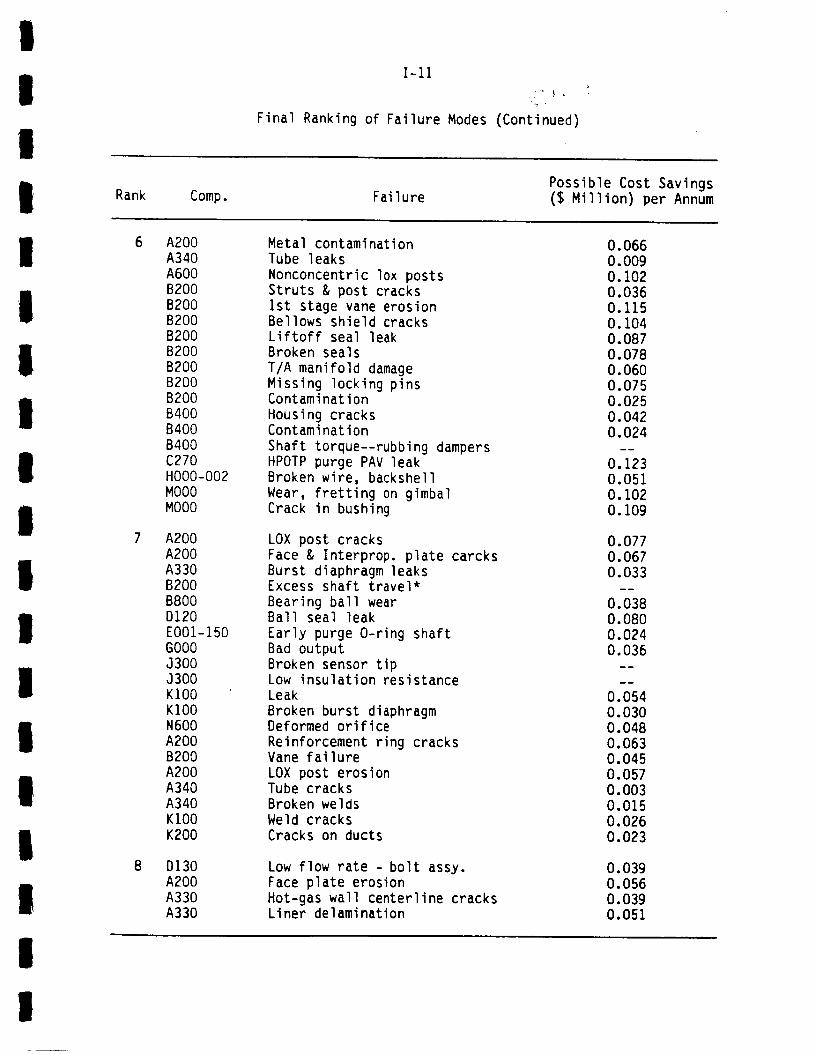
!
!
!
1-11
Final Ranking of Failure Modes (Continued)
I Rank Comp. FailurePossible Cost Savings($ Million) per Annum
I
IIIll
II
l
I
II
l
6 A200
A340A600
B200
B200B200
B200
B200B200
B200
B200B400
B400
B400
C270
HO00-O02
MOO0MOO0
7 A200A200
A330
B200B800
D120
E001-150
GO00
J300J300
KIO0
KIO0N600
A200
B200A200
A340
A340
KIO0
K200
8 D130
A200
A330A330
Metal contaminationTube leaks
Nonconcentric lox postsStruts & post cracks
ist stage vane erosionBellows shield cracksLiftoff seal leak
Broken seals
T/A manifold damage
Missing locking pinsContamination
Housing cracksContamination
Shaft torque--rubbing dampersHPOTP purge PAY leak
Broken wire, backshell
Wear, fretting on gimbal
Crack in bushing
LOX post cracks
Face & Interprop. plate carcks
Burst diaphragm leaksExcess shaft travel*
Bearing ball wearBall seal leak
Early purge O-ring shaft
Bad output
Broken sensor tipLow insulation resistanceLeak
Broken burst diaphragmDeformed orifice
Reinforcement ring cracksVane failure
LOX post erosionTube cracksBroken welds
Weld cracks
Cracks on ducts
Low flow rate - bolt assy.Face plate erosion
Hot-gas wall centerline cracksLiner delamination
0.066
0.009
0.102
0.0360.115
0.104
0.0870.078
0.060
0.0750.025
0.042
0.024
0.123
0.051
0.1020.109
0.0770.067
0.033
0.0380.080
0.024
0.036
0.054
0.0300.048
0.0630.045
0.057
0.003
0.0150.026
0.023
0.0390.056
0.039
0.051
I
I

1-12
Final Ranking of Failure Modes (Continued)
!
I
!
Rank Comp. FailurePossible Cost Savings
($ Million) per Annum IA330A340A700A700B200B200B200B400B400B400B400B400B600B600B800DI20D300E001-150F800GO00HO00-O02J200J600J800K200K500LO00
AIO0A330A340A340B200B200B200B200B200B200B200B200B400B400B400B400B400B600
Coolant inlet welds mismatch
Outer jacket cracks
LOX post & liner erosionLOX post cracksSheetmetal cracks
T/A manifold cracks
Missing discharge nuts and lugsBearing support wear
Spring lands wearNozzle vane cracks
Turbine blade contamination
Strut damage
Insulation rupture, cracksExcessive torqueContamination
Ball seal leak
Poppet remained open
Wireway leakFID?
Low insulation resistance
Open or short circuit
Bent pin*
Output failure
Output failureContamination
Kink, twist, or compressedProtrusion on seals
ContaminationContamination
Hat band leaks
Misaligned fuel jointsTurbine blade shank cracksInlet duct cracks
Bearing ball dry-lube cracksTurbine end ring cracksBurnt vane
Nickel insulation damageBearing ball wearGouges in vaneStrut cracks
Sheetmetal cracksLiner erosion
Turbine disk rubbing
Shaft travel* - bearing loadingContamination
0.0360.0180.0510.1020.0160.0300.0360.0550.0550.0480.0110.0240.0160.0240.0110.0300.0130.0090.0060.0150.036
0.0400.0300.0170.0170.041
0.0130.0140.0060.0360.0330.0280.0190.0210.0240.0080.0260.0090.0080.0090.0240.036
0.011
I
III
II
II
IIl
iI
II

I
I
I
1-13
Final Ranking of Failure Modes (Continued)
Rank Comp. FailurePossible Cost Savings($ Million) per Annum
I
I
II
II
II
i
i
I
II
10
9 B800
B800
D120
DI30
D130DI40
D150
D300D500
E001-150
E001-150
E001-150J200
J200
J800
KIO0KIO0
L200
N600
A330A330A340
A600
B200
B400
B800Dl10
D130
D300
D500D600
D600
E001-150
E001-150E001-150
E001-150
E001-150E001-140
E001-005
E001-150
E001-150
Shaft torque* - bearing cagefriction
Flange surface undercut
Excessive pressure*Ball seal leakInternal leak
Excessive pressure*Studs overtorqued
LVDT signal erraticValve leak
Seal leakFID?
Electrical problemsOutput drift*
Low output resistance*
Missing dielectric insertJoint overmold debondedTolerances
Loose stretch bolts*
Tolerances
Hot-gas wall erosionWear on strut clevis
Defective temp., & radiometersensors
Contamination
Bearing support cracksStrut erosion
Stator dingContaminationContamination
Contamination
Port 0240.1 leak
LVDT voltage lowContamination
Vent port leakServoswitch failure
Vent port pittingBroken wireway nut
RVDT limit* - engine flashback
Defective O-ring
Sequence valve anomalyContamination
Hydraulic oil wetting
0.0O6
0.010
0.0260.014
0.018
0.0060.012
0.009
0.0170.009
0.0130.009
0.O09
0.3030.005
0.5040.015
0.012
0.006
0.004
0.0040.009
0.003
0.0060.006
0.0050.006
0.008
0.009
0.006
0.006
0.005
0.002
I
I

Final Ranking of
1-14
Failure Modes (Continued)
I
II
Rank Comp. FailurePossible Cost Savings($ Million) per Annum !
10 F800
HO00-O02KIO0
KIO0KIO0
KIO0
K200K200
K200
K300
K300K500
K600
N600
Chaffed wires
Insulation resistance lowJoint boot tear
Nickel insulation cracksSeal cracks
Frost on bellows
Support link cracksDuct wear
Impressions on ring
Misaligned jointContamination
Contamination in joint
Controller cooling duct cracks
Low torque
0.002
0.0030.003
0.003
0.0050.004
0.006
0.0040.006
0.001
0.005
0.0040.0030.005
II
Ii
II
II
i
i
IIII
I
I
i
I
II
II
I
lI
II
l
iI
IIII
APPENDIX J
LISTING OF SSME MEASUREMENTPARAMETERS BY COMPONENT

I
IIII
iI
I
II
liII
II
II
II
!II
iiII
J-1
MEASUREMENTPARAMETERTABLES KEY
F -- Inflight Measurement
G -- Between Flight Measurement
B -- Both Inflight and Between Flight Measurement
D -- Detection of Failure
T -- Trending Information

C__J
0
Z
(.9I
I-.-c_
I
I
0
O
I--
Z
0
oo
|
E
_- E
r- I-
r" u_
Z
GJ
_-C;.
q-
4_
0 iX
la.
0-2
u n:
•__ _=
0
°p
I-
* s..JE
I-
_ 0
c_
o
l_. S. I:: i_ *0 "3 a-_c
,,_ ¢-
_" 0E
0
I
IIII
II
III
II
I
iI
II
II
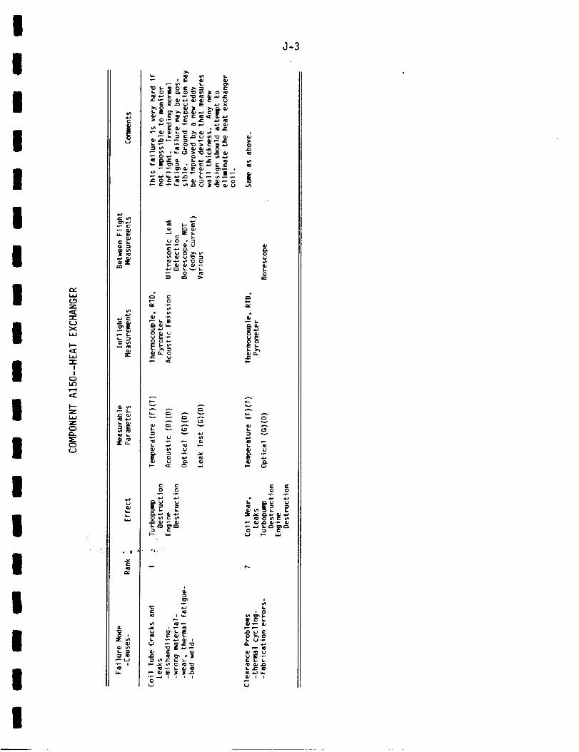
,]-3
I
I
I
I
II
III
i
I
II
I
I=_
(.9-.7
--1--UXI.i.I
l--
W
=r"I!
I--"Z
Z0
C_C.a
is=a
,'- i..
wx
._a ¢=-
X
ii_ I-.
cp
•-i Io
! io
I
_°
§ r_ __
d_
e.
_ ,%-
0
S-O
I=-
v
_- _,_ _,_
S-
0:_0
I

O
¢..)
W
"3
c_
!
!
C_
O
C_
Z
C_
C_.
C_¢..)
t-
Ot..)
GJ
G_e- S,.G_
.C G_C_E
Q_
S,. C_E
Qj n_
GJ
G;
XG_
C_
O'O
_|_,_
J-4
O_ r_
_ o
°_ _ o_ _-
z z z _1--
_ g
O_ O
_- <
O
o_S- I:
0 C_
_ _._
GO
o_
_ E
G_>_
_-_EO c_ O
A _
_
c_
C_
c
O _ _O
1- ¢,_0 _o_ _
S,- _ O"
= OE11
c_
o
I
i
I
IIi
II
II
I
II
II
II
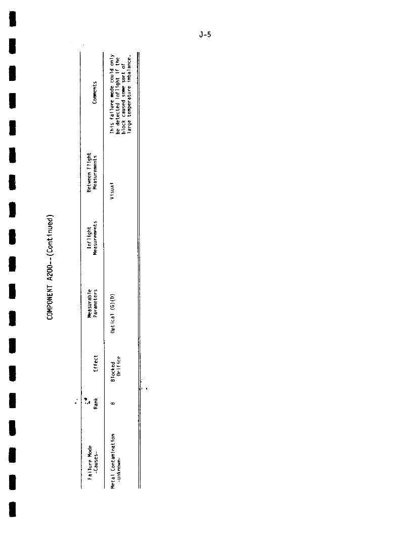
I
I
I
I
I
I
I
I
I
l
I
I
I
i
l
lI
I
¢)
r-
°p..
0
I
I
C)
0
I'--
Z
I.¢J
ZC)
C)
¢--)
|
C
CU
C ¢n
Z
_ E
• _ _
0
OC_
o
¢.-°_
s--
,]-5
I
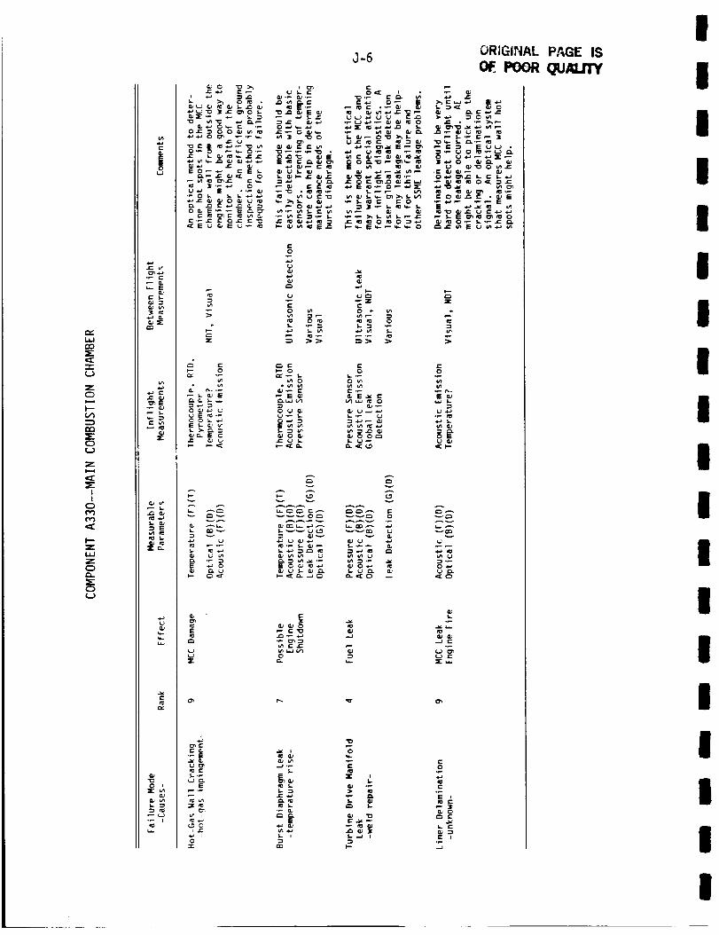
LAJrn
=[
"r
C3
)--
rn
C)
(.J
Z
I
!
O
t'v')('_
Z
laJ
Z
C:)
C)
(.J
r-
Jo
.c v_
u_ E
QJ w
Q_
a,a c
O_,E
c
_ E
o i
_ _ __=_'_ _o =_ _
_J-. r= _ :=j=
%
g
J-6 OR;GINAL PAGE IS
POOR(NALffY" . .T-
"Oo_ r-
• _.
_ O'F=,b'- = 5,,,..
o
,.a
• _ _ z
ro 0 _0 *0 _0 0
0 0
v
A
_v
-_,_o"_ "_ ._,.T.
£:
__ ._ ._
-'_, ._-_(u o
_ _ °_
I,.-I_ ._
I
II
II
II
II
I
II
I
II
IIII

I
I
I
I
I
i
I
I
I
I
I
I
I
I
I
I
I
I
I
(2)
C:
,p-
4-)C:
0
I
I
E)
_E
Z
Z
E:)
=EE:)
(.J
e-
3
..E a)
i:: u_
.,Jr
i_ .¢..J
.sr_.
cv
o *Z
_u
q_
Z Z
._ .p ,p
E
u u
_ E
e-
.p
E
_ _, _
a-7
ORIGINAL.PAQI[OF POOR QUALIfy
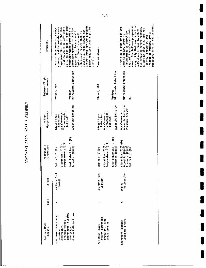
>-
--J
er,
=E
LI.I
l,.l,J
N
N
O
I
I
O_r
l.l,J
E:)
C3l,J
I::
|o
_: i.n
I: I,-
_z
,.E _,C_E•_ ea
2:
i0 .i._
i_i I.
_r_..
a-8
,,_.-_,_._._-___,__
w
o
u
- _ _.;_® "_'_
,.2 _m
; >g g z
g =0,_ .p
o,p
(.9 _:_-- .=:
{=
o
o_
_J :_. I.. i_. O.I::
I--
L.I IO
O0 e-
_ _-'_
c-
o c
I
IIII
II
II
II
I
I
II
III

I
II
II
I
III
lI
Il
II
II
I
r"or'-
4-)c-o
__)
II
o
f-.z
Z
c_
0(.J
Q_
_E
",Jr
to
_r_.
croQ_
_'_ 0 _- "_-_ 0 • _J_,_
t-O
°_
J-9
c
_o c_
i
°_
.,o i _
OR_JN_LP_1[ Ill
_=
_J
(._c.9 ,_
_ ,_ _,
I,,
I

"I
Z
m,."
mm
i,i
O:::
,,,,,
.1J
l.aJ
i.l-
i
I
0C::)
',,,0
,,:l::
I'--
I,i
Z
0
e-
|
_E
X
1_4.J
E
Z:c_
(..)
ii0
0,#
o i
C: r i-. ,,_ E
_ -_
_._.-_'_ _ _
J-10
r_O_
_E
_-._
_==
_3 I.*.
S ._
_ E
_¢3 O Cm
v_
o
E
•_'_ _ =o_
_'_ _. -_o_
O
8 8 8 8 8
,i,,0
___E
_ >_
i--
i_ _ 6m
_ ),=,. _,_(,.0 v S,.. _ (..'0 _
0_
a- N _
Co
Ox_c_
o
v
U
E
C_--
0:-:-
_ _._-_ _.0_ :i t _ Io 1"" i
oZ
_D 0_
¢:0
r- o
0
III
III
II
II
I
II
II
II
II

t
I
I
iI
i
I
I
II
II
I
,,,...
r'..J
><
!
I
C)
r...
Z
i,J.i
Z
C_
C)
•_'_ _ _ ==_"..=o._-.=.,.,._ _.__>_o,...,-,_ _._ _ >,_
.- _._ _ _,_._
5,. ,¢_ It" _._j_ ," ¢/s
oE
0 0
v
_._
G)
Le_
-_._ _ _
J-ll
0
_p
0
0
f..
r-
0
m
In

CL
0
r_
l---
...J
l,J.J
LL.
m,-
C_
L_
-I"-
c._
I
!
0C_
Od
I"
0
C_.
0o
e-
_- E
C s..
CmE
N:I._
vl mmm: l.-
L_
rl:,Y
0 i
C 00_
m:i-
Ca.
OE _ _
"o_._•"2 .'2
I,,,-
u_
O0 I,. _-
i,,-
J-12
..-
5-
0
v_ 0
I- 00 v_
.=
e_o_ 0_
c_
F-
v
¢- t_ .p
o
LC_
5- '--_ E
e"0
O_
_ E_ -'_,__
e-
r-e"
c-O
0
c-
O _
o _ _
e-
u
I
IIII
II
II
II
I
I
III
III
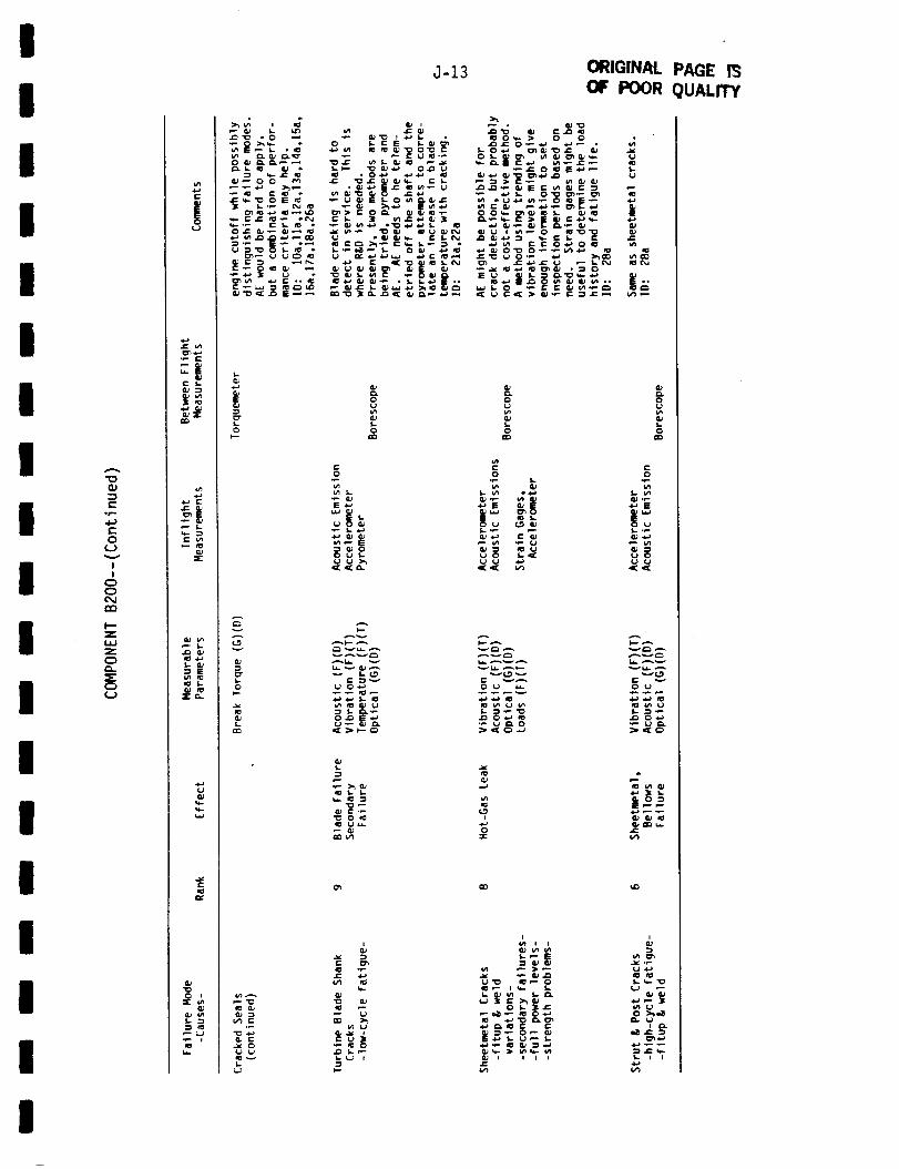
iI
I
II
II
II
II
II
I
II
II
*r.-
O
C..}v
I
I
O
C_
i'--Z
¢J=l
Z
0
Z
!
,p r-
c
Z
Lr_ i_• P 5.W _P
3E: C,.
O iE
L
J-13
-_=_ _:o___i_ _
(pE
OI,--
2
O
O
t-O
E-'-'
u
_ _00 uI-uu_,_.
A V
A_. v
:}
_ U
ORIGINAL PAGE 13
OF POOR QUALITY
_ Ow- > 0 0
_, ,._ | _ _..
0
0
u _
O
s.¢,
O
,,_E
_._ 0t.} u
,_,_
0 U _
_ U _0
v¢.9
O _-J
I
:Ze-
CO _D
i i I I
I.) ,i-_
I.. w- "1_
U0 >_,_
i _.
. ._
I
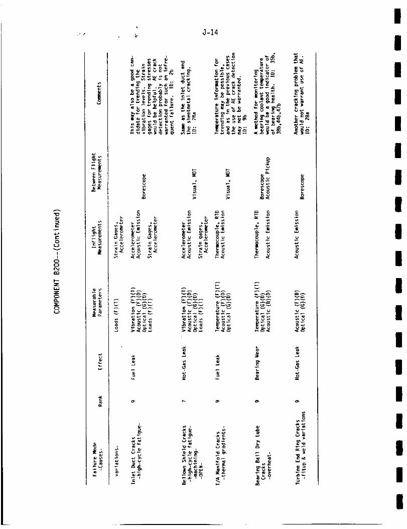
(1)
(-°f--
4-)t-O
v
I!
Ooc_Jrr_
z
zC_
C:)
t-
!
• ro
_n4-)
s-
to ._-J
_E
_" c1.
(.JO_q-q..w
r-
r_
w
_-.oo_.o_ _ _
o
e-o
_o
i-0
.[
J-14
,.. .V) 0 q" ,,_: '
._o _ _ o_
,- ,- o
• _ 0 _J 0
o _- 0 0
0 _ _
v _
&0
cg
_ _._ t'_l_ "
IIII
!II
II
I
II
I
III
III
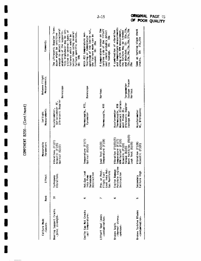
I
I
I
I
I
I
I
I
I
I
I
I
I
I
I
I
l
I
"C3
4-}
C
0
(..J
II
C)
C)
C_J
rn
I--"Z
Z
C)
C)
<_)
|
_- E
CU_"
2cu
_E
c
._ Cu
Eal_
fo I-
X"
e.-
_.
e_
8 8¢n e_
o onn
M=,
•- _ a_ _0
E 0
0,0 f.D Or-
C)
¢_) .l::
1. t-O
°_ o
_ 0
J-15
r- W,_ ,,_
OIw>_
_-
_'_ _
0
ORIGINAL PAGE _3
OF POOR QUALITY
I(":- "
_: _ _..
"_ O0
f_ o I-
I.. a.) al_ a.: GJ aaa.)
W
- _ _O_ 0 E_O
I. I¢ ¢: _ C3 al_ QJ
tJ I "_
I:I.I= _ t.- . i_ _,..--
0 I _- 1 0 I I 0
I

"O
°r'-
4-)
O
(__v
I
I
O
O
OD
t--
I.I..I
Z
O
O
°_ _-
r'- 5.-
3
._ e-
_E• m 0._
ii_ I,-
G.,,e-
1=
i'__
¢,.- t,-o O
_-, t-
_o _-._,
__
d,
J-16
I
• , (_ I:: E
C: I.-
0 _ 0
C_
i..._ _ _ {'_
_ c
_ 0 _
C I
I
I
II
III
II
I
II
I
III
III
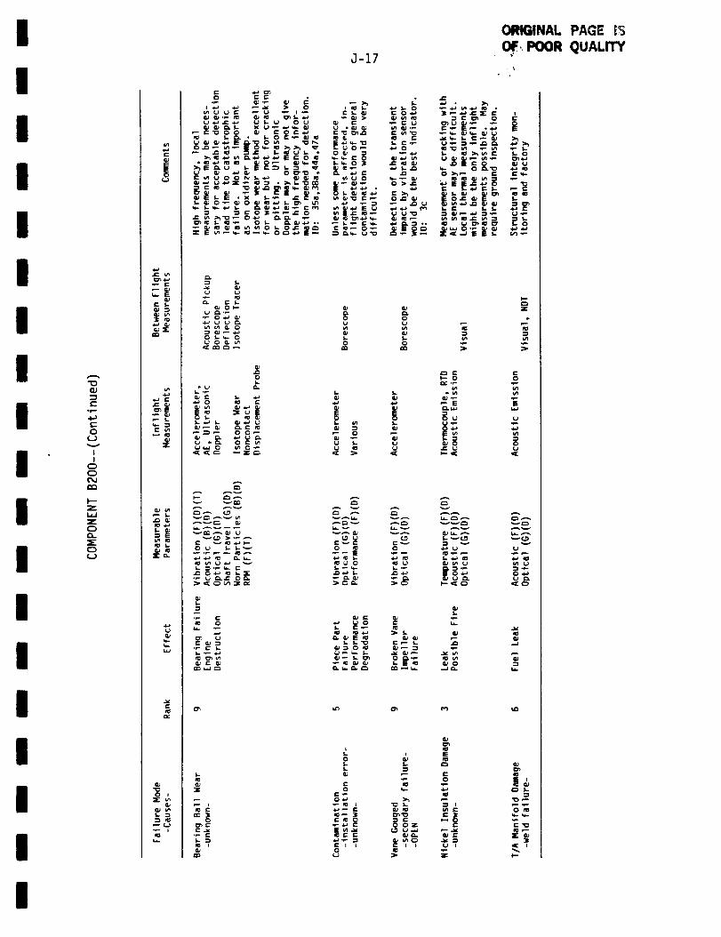
I
ig
I
!II
!
iII
II
I
II
II
e-0_
t-
o
v
i
i
0Q
I--
Z
L_
C:)
(1.
C:)
(.)
t.-
|{_)
_u£; I.QJ
_E
C u_
:E
._ Qp_4.b
q.k_
c_
Qp
J-17
0 °
0 I _ I,..( .wa ,wwa _,._c
12._-
._o_
e_oI-
E_ 2t uE
ORIGINAL PAGE tF_
• 0@',..POOR QUALITY
"_ f.9
o-" _
_. e._0 0
0 o
l_ 1- I-I-- 0 0
I-
0
CU
0 E
0 _-
i
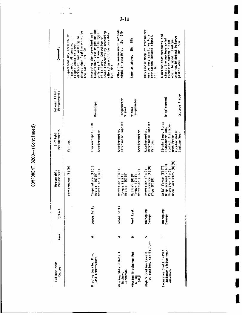
(I)
(-.
°_
4.-)c=
0
I
I
0
0
¢:Q
I---
Z
0
0
0
e-
!
o_
Cu
_c r:
mm
.1: Q.__E
e- Im
Z
E
I=1
_=_.
tt_
0 IZ
•_ ,
J-18
s.-4)
Owe- .,.) -_
°* _ _
o
s- s-
O 0'_ _ 0
S.
ooo_ _ _o(_ S*- 0 S- S.. 0 _
_ _ _ _=
_ 0
L_
0
E._._
E_-
o
•_ s.-
OE
c_
_7
o
z c_
III
III
II
II
II
I
II
II
II

I
I
I
I
I
I
i
I
I
I
I
i
I
I
I
I
I
I
r,
0..
0
r,,,.
N
,,--,
xo
-I-
!
!
0
C>
F--Z
Z
0
_r"C:)o
_- E
_" 5,.GJ
w
n_
r-
O_ar
Qj u_
_JL/_ n:_p L
q..
OJ
I.. :}AP
x_
--_ _
_*0_
,*,,) 0 ,,_ 0
.or____'_e_
1.
5
cp I,-
v_w _ 0
L
o,_
c-o
cp u.__ (i.I w
cpe.)
cp
_ °
._ ._ _ _ I---_/" _-_
I,---*"-, (=9
o
.E:__ _
0
_'; _
0 I
C 0
I--L
e_
aO'_ ICP _"
I

"0
l=.°_
c-
O
v
II
0
0
D_
Z
0
0
I
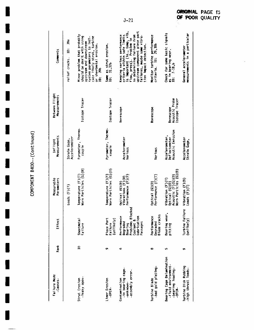
II
I
II
II
II
II
II
II
I
II
-,Ic-
c-o
I
I
0c_
l.--
U.J
Z
o
c_
|0
r- 5-
_u_"mm
•i.J (-
,I= I.
m=
0 i
c
o 0
E
_ cuo
0 _
_ 00
l.- I
J-21
I., _ I: ¢/I i= _ IE ,_
_:_:r;_ "
0 0
0 0
0(IJ-_
0
I,-
A _A _
l_ L_. '_._ 1_ I'_
0 ,¢I
"0
0
uI.
¢: I: _ GJ0 0 P
0.--I ¢.)
.ORIGINAL PAGE I_OF POOR QUALITY
I.
S
_- " U t-
O IU ,"*
p_ _ L
0_
I,-00
c-O
AA
0 U OU.
0
i- I I
,P
I

t'-°r--
¢-.o(..)
i
I
c)c),q-nn
I--z
zC)G.
C)o
£:
|
_- Ln
Z
0 i
m=
_';.
I:; ,.n 0_._.)
o._
o
_8
v_
vLOv
J-22
: (I_ 4,J "_: 4,") 4,,) _
| :i o'-_o- .oo o
e.-o
8I.-o
nn
0
W_ 0
_ 0
A _
ep
g-v
v
c
I-
",4
0
0
E._E
&e-
ra• _ 0
c-o
0
0 _ C_
_ c
._
I.
S-O
C:v
0
V_
C
mmO_
_D
w
o"S-Oi-
s..Q=
.c
c_
-r-
II
IIIII
I
II
I
II
!I
II
II

r_
3E
O
r_
I'-
._J
r_r_
C_
I
I
c_
I--"
Z
C_
o
c
!
C t.
4-_ *-
L,_ :3
c;Z
GJ
t_ u=m s.-
0J
I. s-
t--
O._
°_
t,J
_Av_
v _ AAV
_._ _ _
t=
r_ C_O
I.
i_ i I I_ i (.# Ir- o x
J-23
t- o_
PAGE

.=_
C_
n,."
.--J
W
1,4J
.=I
!I
C_
C:)
aO
mn
I---Z
Z
C_
G..
c_
r-
!
i,m]l n=,i.l Qj
mn
_E
e- Im
,s-_.
w
cu"o0 i
J-24
>_
,i,_-_ _ _"_ _ ._., ._.._._,..__ _-_ ._._ _ _ t,.-
• .=_
o.
0 0 o,,, N
L)
v _
>_._
G.e-EO
g_
0 0
_ _ _=_
0
_'_ i=E:
i.)s,.Ill
i
_o_
e-
_*_ C_0 S*. _ I
!I
II
III
II
II
II
I
II
iII
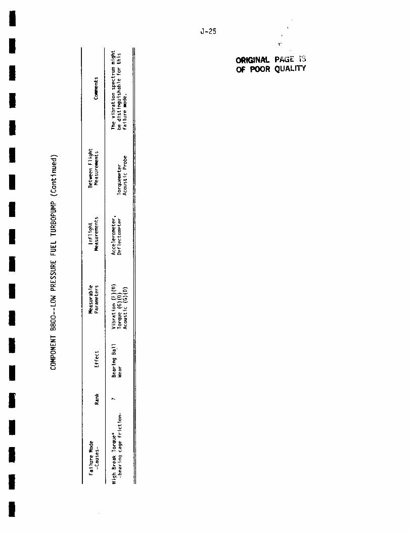
I
I
I
I
I
i
I
I
I
I
I
I
I
I
I
I
I
I
I
°i=.
4-)
0
0
....J
I.J..
C_
C_
rv"
0
..J
!
I
0
0O0
n-i
t'--
Z
0
C:)0
(.J
._ ¢=.
F..l_e- l..
_E
£: wf0
w
:[o,.
.¢..)u
q..
e-
s- "_
p- (=.)
_0
.¢..)
.1:: u_
E.l-_
_ v') I,
0
s.- 00 o
v _ t._9
e-c=_
J_ I,- 0•_ 0',.)
n_
e-
0
f.. o_
(uj: ,-_
..r-
J-25
ORIGINAL PAGE _OF POOR QUALITY
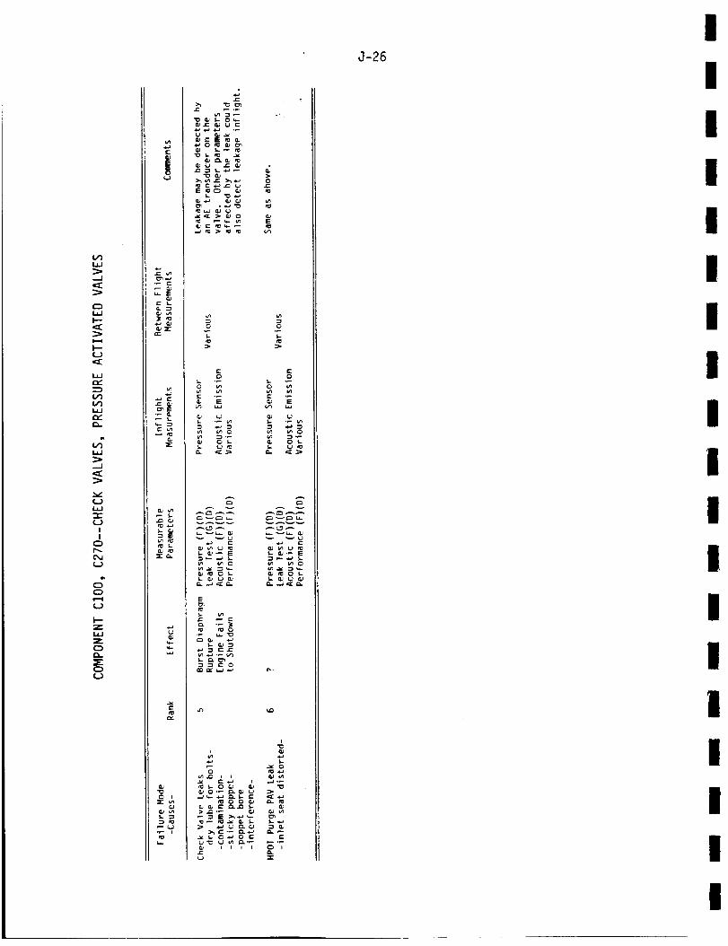
W
(.D
_2W
-r
I!
0
d
I"-
Z
i-
£: s.
3 _
_E
_ E
X _
>, -_
.,J
"Z "Z
e- co o
_ g z _ P,T.
_ ._._ E _._
E
e_
J-26
I
I
I
IIII
I
I
II
II
Ii
III
I
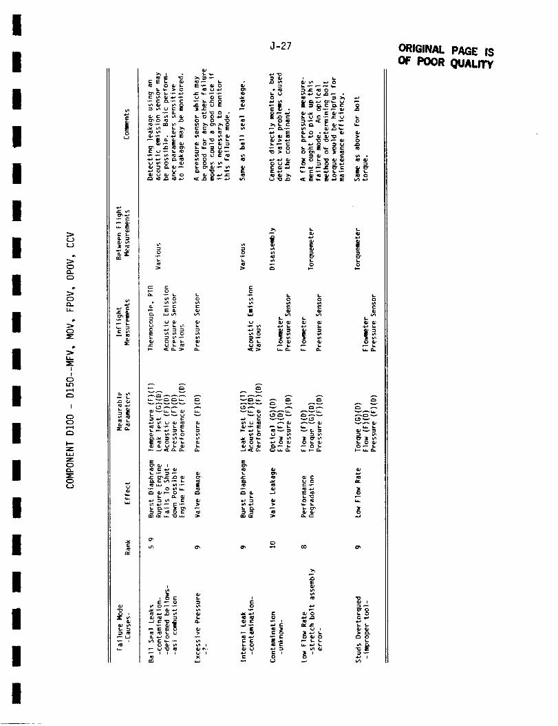
i
I
I
Ii!
Ii!
III
I
II
Ii
I
U
O
(=)
>-O
IJ-
O
I
!O
I
O
O
I--Z
Z
O
o
._ c-
t- s-
_E
I,..
@E
E
O i
I,-
_(.,_
;'3 _ ._
_ ,-'_. _, _ _
g"- §,.__ _ 0
o 0
_--_
_ _'_ _ _
_ x
J-27
_ _ 5. ,__-.
_" • O_ _ "_
_,_ _'r. '__ ___
{,.j'_
E
oc
o_
E
I.. O _
(,-._,.
w_
O
O
._ I I= I
E
_,,1=
0
_o
ORIGINAL PAGE ISOF POOR QUALITY
i

Z
c)
.=J
zc3
.=J
(,=)
(..)
Z
c_
zc_
xC_(.9
gC:)_Ji,
I--
!
!
d
dm
I---z
I=
|
_ E
<1.-, c
•_ (l#
c
Z
E
i1= $..
0 i
f,.- =1
t.,=
J-28
o
E
i
o.1=
z
_"i1= _ iI-
.1::
0
m:
0
el:
(uE
0
o
0 0 _0 _0
C=_E _E O_E 0 _E
0 C,
r-._
_ Ex 0
0
C
o "
0 0
r.O
e-.
o_
_b,.-GJ
(U..J
II
I
i
III
II
II
II
I
IIi
II

I
II
IIII
I
I1
I!
I
II
Ii
II
C_
W
-r
0
I
I
0
O
0:)
Z
LLJ
ZC_
c:)(_)
e-
|o
°_
mm
_E
-' E
0 I
L :3
3 -6
E_
e0
"o
G)._
_ E
_'_ ._
_o.__ _-
e-
._ o=
_5 __, ._
J-29
ORIGINAL PAGE 13
OF POOR QUALITY
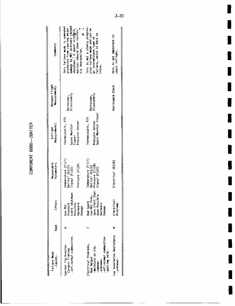
LI.I
l---
Z
I
I
C)
C)
C)
I"--
Z
L_J
Z
0
C)f._)
r-
|o
f" I,-
C
X
= E
w
•_. _-._
_*__ ._ .
_= _>,-_.,
_'_E _.E
e-
,_._ _ _.
_._ _ _ ,-
_ _ _'_-'-
0
O_e-w_
r-
_e
v
"r.
J-30
r--. CO
C)
D J=
._- __-._ _
0
O_ _ i= OJ
..-, e
II!
IIII
I
Ii
I
I
I
III
iII
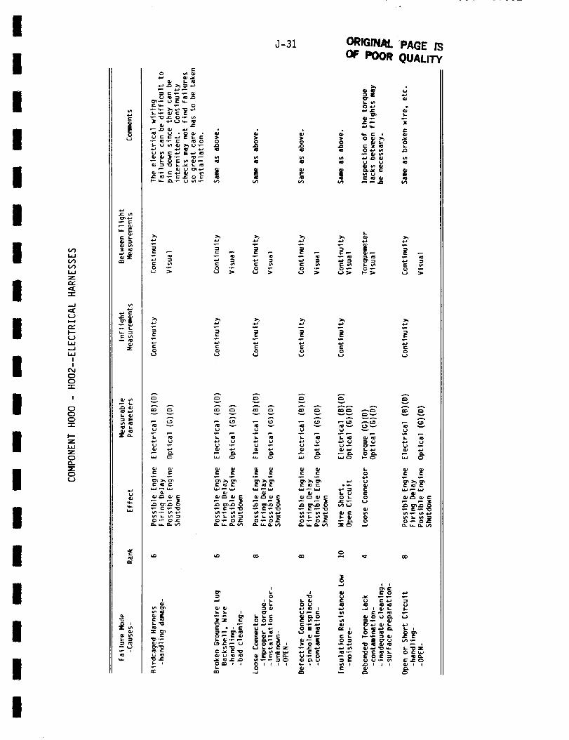
IJ-31 ORIQINN.-PAGE m
i OF POOR QUALITY0 _n
(/1W
v)LI.J
Z
m.-":E"1-
.-J
u
re,-I-ui,,
...J
I.lJ
I
I
CMC:)C3-r-
I
E)OC).-1-
p-Z
C_O.:EE)U
|
ear- i..
_X
•i_ i=
_E
v,_ =_
I.. Q)" Ei_ m:l
{u
_r,j
"r: '
I
I
II
I
I
I
II
I
II
I
II
I
"_ J=: I::: _ 4)
c= = =
f..
r-
C
u
_.._ _-
A
E
EU
L I
i I
]_3[ '- 000 I" w ._
I. i1_
t
I
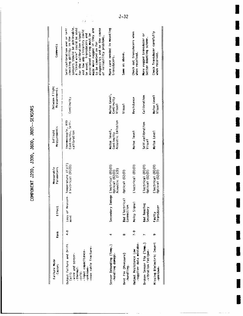
nr
C)
Z
II
C3
C)
CO
C)
_0
"3
JC)
'--3
C)
'--3
l'--
Z
Z
0
C)
0
c
|
===
_._ s=•_ (LJ
w..- _3_: u*,
_ E
e-
o i
J-32
i
_._._ _ _ ___ ._ o_ °_ o_
(3
-_ ._
:>:
==,_ _ _ _
°_ _ _
(U -_--)
E
_ E
N_
I. i:: r- I,-
i
== "G "
i
e- I,,. i (3 _
III
II
IIl
I
II
i
II
III
ii
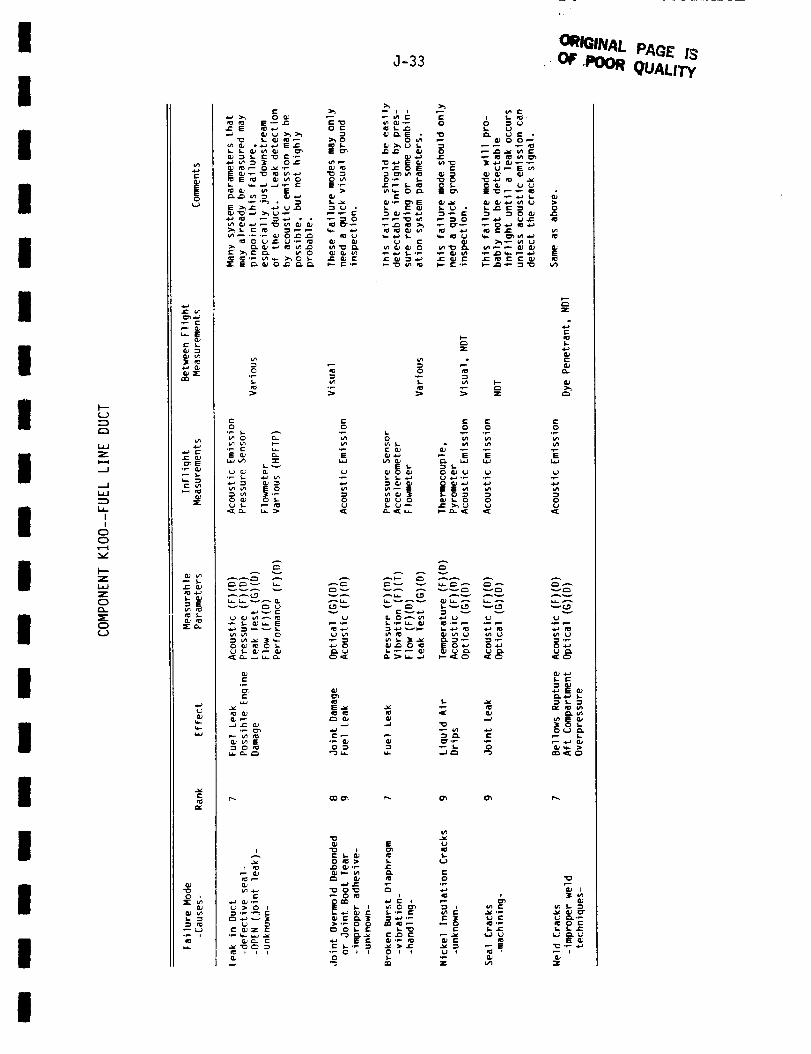
III
II
I
II
II
III
I
I
II
I
I---
U
Zt=..q
.--J
II
C_
0
I--"Z
Z
C_CL
O
(..)
r-
|
• P c
0_c s.
3 ro
.i= aJ_E
C vl
_r
eJ
_E
e= _..
=£c,.
eJ
fo
Q)
•-i n=
_ '" _..__ o _"
_ :._-_ _;_ _._
s_o_R_ _..
r- r-o o
w
=_..v
_-_ _ _l_ _'_
i-
_- t_
_ -_
_ >_'_
J-33ORIGINAL PAe£ _3
oF ,Poo_ QUAuTy
>_ >_
j= i_ =1 <.a J= _J IE j= i_ e- e- i_ i_
.p=) :) z
*- c-o o 0
0
x
(u>_
c=
_. F-- L_. r_ _
W_ 4J _ U vlU
I.-
.p:1 "P _- 0
_'{.9
U
_:[C3
1, E
_. 4-) I,
_ E
_t--w _.
_ (3 r0 ,_a _'l I
t, .1-_ _J I:: (-'PIE
• _ 0 i I 0 I t
u
E
.p
2_r-
_ E
_. fw. t-
I

(i.
.p-
0(..)
v
ill"
(..)
W
Z
I,I
l
!
0
0
l l"Z
l.l.I
Z
C)
5"
0
!
_I E
c_
_E
E
_'c;-
o l
l,-
"vc _
e'-_ S,- "_
g
E°_
0 _
0
0
_. (_ 0
?'? _l
,.1-341
II
I
I
I
I
I
I
I
I
II
II
II
II
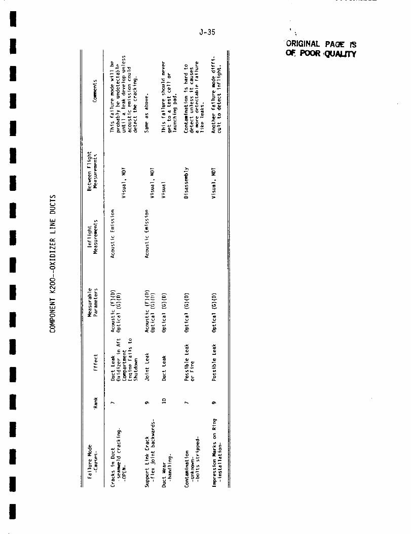
I
I
I
I
I
I
I
I
I
I
I
I
I
I
I
I
I
I
I--"
l.--,
l.l=l
Z¢=.=l
.--I
i.l=/
NI..==i
I..==i
X
O
I
I
C_
C_
Z
LIJ
Z
0lm
C_
{_}
¢.-
|
._ i=-
E
c I.-
c l.m
.9 E
0 ,X
_l..#
J-35
°_
I
°_ _ .
"0
,_- o
E E
E
,.."
._
-¢ .,= s-_°_
==- O
_=_
¢J
Ill
-_ o-
•_ e'.a
,1_ I= 0
0
c-
O
'- 0
O--
t
ORIGINAL PAQ_
oF POOR=QU/UJ'rY
I
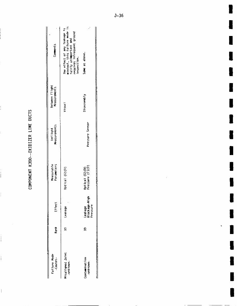
I--u
I.¢d
Z
..d
N
xCD
I
I
0
C_
zlud
Z
¢D
CDc_)
8
°_ _-
_- E
_E
C _n
L G.JEn_
src_.
u
w
0 I
e: E 0
,_ E r" * 0
g .g o ®
E
e-
0
•r- 0
sr
.i.,I
G_ G_
0
C
|-_
0
J-36I
II
II
I
I
I
I
II
I
I
I
III
I
I
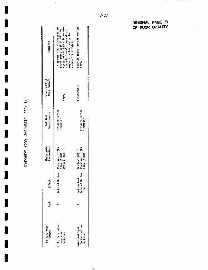
i
I
I
III
I
II
I
III
I
i.;_l
Z
....i
0
-r"
I--
=E:
Z
I
|
O
O
o(...)
_E
=E:
E
_-c,.
J-37
ORIGINAL PAGE P3
OF POOR QUALITY

.-./
0
F--
F--
II
0
0
C:)
F--
Z
Z
O
o
r-
t_._
r- S..
_E• _ (3.)
=E
lIE c_..
_ ._ _'_ ,, g
= ,, _._ _-._
_ >_
E E
'i '
J-38
II
III
II
II
II
I
II
Ii
III
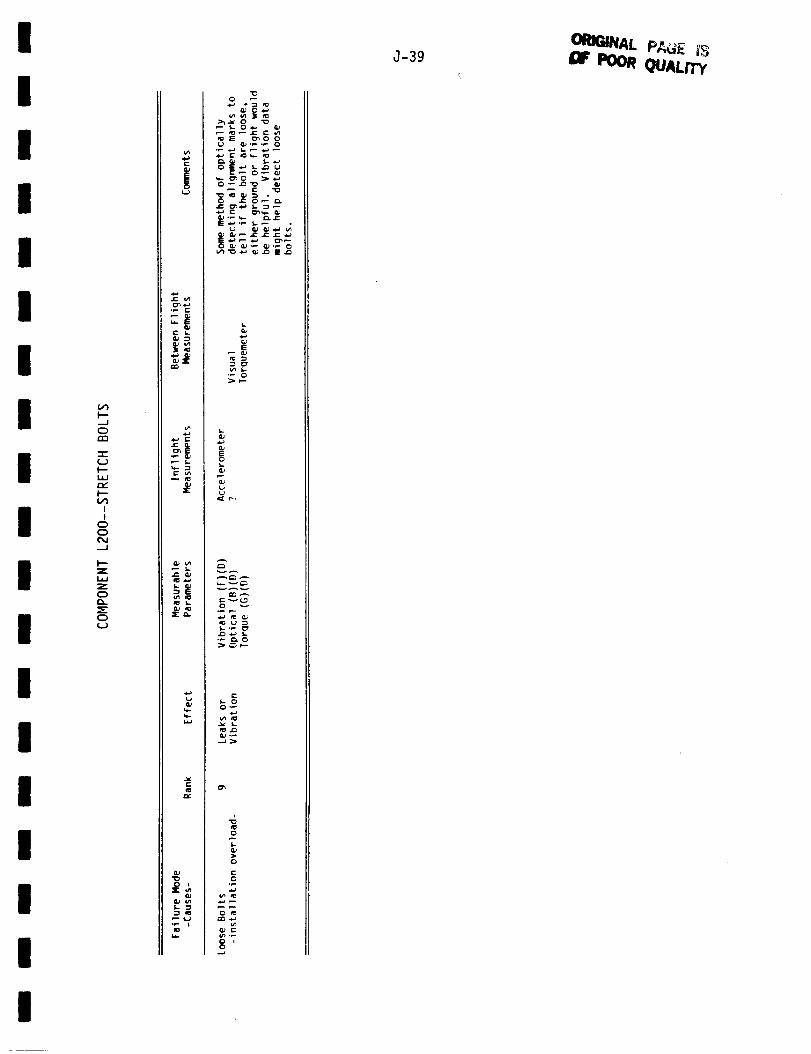
I
I
I
I
I
I
I
I
I
I
I
I
I
I
I
I
I
J-39 _ POOR QUAL/TY!i
_- E(U
_r"mm
_rcb.
Q#
r.-
w
,--J
0
r_
)--
I
!
C_
Z
Z
0
0
_ S 0_00
,_'_ _ g .=
E
o
9=[ r..
A
cI;;_
,.g
C)
O
e-O
mm,.)
0 i0
I

.--J
n'_
I
IC:_
C)
I--
Z
Z
C)
C)0
f-
!
_L_
_E
c LnN
cu
._ cuep_.J5..•"_ IZ
npxa-
cue,..
f-
(uqoo iar
{u
rip
._ >_
c
_ u
x z
._
_ EE_
I,,-
._wE _ E
r,._ -.._ ¢.,,,_-,J
®_._ "_
,.]-40
III
I
III
I
II
II
I
II
II
II

l J-41
i "00__ -._-0 ORIGINAL PAGE IS;
i " _ -_:_[ _ OF POOR QUALITY
_':8=__
(,..}
m,,"
0
i,i
l,J
!
!
Z
Z
W
Z
c)f_
t.m
C
_- E
mm
',Jr" =.
QC
Q#
I,a...
I
I
II
III
II
I
II
II
S-
op .p
0
,I=
A _
0 _.
c
I

J-42
(THIS PAGE INTENTIONALLY BLANK)
II
II
III
I
II
II
I
II
IIII