e-space - college of engineering | umass · pdf filerevised system requirements input...
TRANSCRIPT

E-SpaceSpencer Pietryka, Steve Bevacqua, Jonathan Scharf

Revised System Requirements
Input Specifications 120 VAC at 60Hz
Frequency 6.78 MHz
Distance/Range 10 cm
Minimum Output Power 2.5W
Minimum Wireless Transfer Efficiency ≥40%
Minimum Total System Efficiency ≥10%
Maximum Receiver Size 4.54 in X 2.31 in
• Changed minimum output power from 3.3W to 2.5W based on minimum USB charging requirements
• Changed final range to 10 cm

Team Responsibilities
December January February March April
Spencer Pietryka
Increase Power
SWR Measure, Control Algorithms
Coil Redesign
Control Circuitry
Repeater
Rectifier, Voltage Regulation
PCB Design/Case Design
Jon Scharf
Steve Bevacqua
Impedance Matching
Oscillator Design/Integration
Gantt Chart from MDR

Projected Block Diagram
Transmitter
Receiver
Repeater (Optional)
DC/RFOscillator
Directional Coupler
Tunable Impedance
Match
SWR Measure
Control Circuitry
TransmittingCoil
ReceivingCoil
RF/DCRectifier
DC/DC Converter
ChargingDevice
Impedance Match
AC/DCConverter
Gap/Distance: 0.25m
Steve
Jon
Spencer
6.78 MHzResonant Signal
ACMains
Input120 VAC
PowerAmplifier

Oscillator
• Epson SG-210STF 6.7800ML Crystal Oscillator
• Stable 6.78 MHz frequency of oscillation
• Supply of 1.6V-3.6V and 1.8mA
• Output amplitude is directly proportional to supply voltage
5

Power Amplifier
• Linear power amplifier• Input 1mW-5mW• 40dB gain, 45W max output power• 3MHz-30MHz input frequency range• SMA connectors on input and output
6
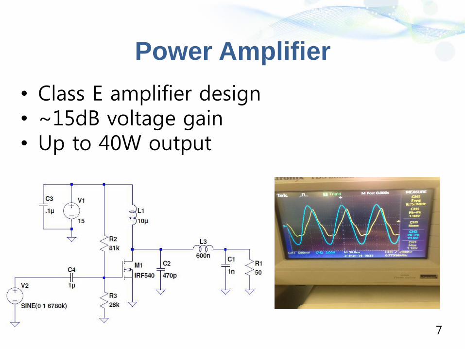
Power Amplifier
• Class E amplifier design• ~15dB voltage gain• Up to 40W output
7

Directional Coupler
● Goal: Measure incident and reflected power from transmitting coil to quantify match
● Mini-Circuits SYDC-20-31HP+ Bi-directional Coupler● 0.07 dB mainline loss ● 50 W power handling capability● >41 dB directivity ● 20.4 dB coupling ● 36 dB return loss
8

SWR Measure
• Goal: Use coupled ports from bi-directional coupler to measure incident and reflected powers and provide proportional DC voltage
• Maxim Integrated MAX2016 LF-to-2.5GHz Dual Logarithmic Detector
• RF Input Power Range: -70 to +10 dBm
9

Coil Design
Waffenschmidt, Eberhard, and Toine Staring. "Limitation of inductive power transfer for consumer applications." In Power Electronics and Applications, 2009. EPE'09. 13th European Conference on, pp. 1-10. IEEE, 2009.
Recall Transmitter Limitation Due To Reciever Size:
10

Coil Design
Purchased Coil:
11
Coil Design Limited to ~175 mm Outer Diameter

Coil Design
B. H. Waters, B. J. Mahoney, Gunbok Lee and J. R. Smith, "Optimal coil size ratios for wireless power transfer applications," Circuits and Systems (ISCAS), 2014 IEEE International Symposium on, Melbourne VIC, 2014, pp. 2045-2048.
N, number of turns
D_0, Outer Diameter
p, Spacing between turns
w, Wire Diameter
D_i, Inner Diameter
l, total wire length
a, winding radius
c, radial depth
f, Resonant Frequency
12

Coupling Factor and Coefficient Calculation
Rafael Mendes Duarte and Gordana Klaric Felic, “Analysis of the Coupling Coefficient in Inductive Energy Transfer Systems,” Active and
Passive Electronic Components, vol. 2014, Article ID 951624, 6 pages, 2014. doi:10.1155/2014/951624
13

Variable Effects
14
Quality Factor as a Function of Number of Turns
Quality Factor as a Function of Frequency

Variable Effects
15
Quality Factor as a Function of Turn Spacing
Coupling Coefficient as a Function of Distance

Variable Effects
16
Quality Factor as Function of Outer Diameter
Quality Factor as Function of Wire Diameter

3 Dimensional Analysis on Variables
17
Quality Factor as Function of Turns and Outer Diameter
Quality Factor as Function of Turns and Wire Diameter

3 Dimensional Analysis on Variables
18
Quality Factor as Function of Outer Diameter and Wire Diameter

Real Vs. Theoretical (Transmitter)
Picked Values for Transmitting Coil• D_0 = 175mm• w = 2.05 mm (12AWG)• N = 23 turns• s = As close to zero as possible
Theoretical Values:
Q_Factor = 3544 C = 6.602 pF
L= 83.233 uH R (AC) = .9440 ohms
Measured Values
Q_Factor = 5137.058 C = assumed 0 F
L = 61.5 uH R(AC) = .51 ohms
19

Impedance Matching
From Z_in, we
calculated the impedance
matching network values by
setting Z_in to be our
load (R_L+jX_L).
Where,
Bhutada, Manasi, Vikaram Singh, and Chirag Warty. "Transmission ofWireless Power in two-coil and four-coil systems using coupled mode theory." In Aerospace Conference, 2015 IEEE, pp. 1-8. IEEE, 2015.
20

Impedance Matching Networks
Several Impedance MatchingNetworks were created and the values determined through online calculators and matlab scripts.
L-Model Networks
Pi-Model Network
21

Self Capacitance of Transmitter Coil
22
•Transmitting Coil Self Resonating
Frequency is at 320 KHz
•C is actually 4.77 nF
•Impedance @6.78 MHz = -5.8492j
•Series inductance needed to tune to
resonance
At Resonance
• L = 4.5 uH
• R = .1422
• Q Factor = 1359.2
Receiver Coil Change

Driving Coil
23
• Used a 3 Coil System to better improve Matching
• Steps down voltage
• Driving Coil: 55 turns & 22 AWG
Zhao, Qiang, Anna Wang, and Hao Wang. "Structure Analysis of Magnetic Coupling Resonant for Wireless Power Transmission System." (2015).
Future: Impedance match to driving coil

Demonstration
• CDR Deliverables Met:– Implement impedance match network
for 10 cm– Final coil sizes constructed – Effectively measure SWR on line
• CDR Deliverables Not Met:– Demonstrate system output: 2.5 W over 10 cm
24

Demo

FDR Goals
• Deliver 2.5W over 10 cm distance• Deliver power through USB to phone’s charging
port• Package transmitting circuitry and house
receiving circuitry in a phone case• Switchable impedance matching network
dependent on SWR measurements• Oscillator fully integrated• Power supply selected and implemented

Questions and Comments