pigrrl 2 - adafruit industries · i ran adafruit’s retrogame installer script and rebooted, ......
TRANSCRIPT

PiGRRL 2Created by Ruiz Brothers
Last updated on 2018-08-22 03:51:53 PM UTC

2555667
88
999
10101212
1313131415161616
1617
19192021222324252626
282828
30303132323434
Guide Contents
Guide ContentsOverview
Raspberry Pi Retro Game ConsoleEasier to build!Project ExpectationsAdafruit PartsTools and Supplies
Circuit DiagramWired Connections
3D PrintingMaterial OptionsPartsDimensionsTap Screw HolesTest Fit OpeningsFinishing Parts
SoftwareDownload & Burn RetroPieSetup RetroPieInstall PiTFT (fbcp) SupportInstalling Keypress (retrogame) support
Uploading ROMsExiting ROMsRemapping Controls
Testing ControlsDefault Controls
GamepadPiGRRL Gamepad DesignPiGRRL Gamepad PCBInstall IC Box HeaderSolder IC Box HeaderPrep 6mm Tactile ButtonsInstall 6mm Tactile ButtonsSolder Buttons to Gamepad PCBSoldered Gamepad PCBTap Gamepad PCB Mounting Holes
PiTFT DisplayGPIO #18 - LED BacklightingCut Trace #18
PiCablePiCable ResizingMeasure, Mark and Cut Ribbon CableCut CableRemoving ConnectorPeel Cable from ConnectorInstall Connector to Shortened Ribbon Cable
© Adafruit Industries https://learn.adafruit.com/pigrrl-2 Page 2 of 86
3636
383839404142
43434445454547484849
5050505152
5353535454
56565758595960
616162646565666768696971727374
Mash Top Piece to ConnectorShortened Pi Ribbon Cable
Amp & SpeakerPrep PAM8302 AmpMeasure Wires for Amp and SpeakerStrip and Tin WiresConnect Wires to SpeakerConnect Wires to Amp
Power CircuitPrep PowerBoost 1000CMeasure Wires for PowerBoost and AmpConnect Amp to PowerBoost 1000CConnected Amp, Speaker and PowerBoost 1000CTest fit Power SwitchPrep Slide SwitchConnect Wires to SwitchConnect Switch to PowerBoost 1000CWired Power Circuit
Pi AudioPrep Wires for Rasp Pi AudioPrep Raspberry Pi Audio PinsConnect Wires to Raspberry PiConnect Wires to Amp
Shoulder ButtonsPrep 12mm Tactile ButtonsPrep Wires for Shoulder ButtonsConnect Wires to ButtonsShoulder Buttons
Final ConnectionsPrep Wires for Gamepad PCBPrep Power Pins on Gamepad PCBConnect Shoulder Buttons to Gamepad PCBConnect Gamepad PCB to PowerBoost 1000CFinal Wired ComponentsTest Components
Mount ComponentsInstall 2.8" PiTFTInstall Gamepad PCBConnect Pi CableConnected PiTFT and GamepadInstall SpeakerShoulder Button MountShoulder Button (cont.)Install Shoulder Button MountInstall SwitchInstall Raspberry Pi 2Mount PowerBoost 1000CMount AmpTest PowerBoost CircuitInstall Lipo Battery
© Adafruit Industries https://learn.adafruit.com/pigrrl-2 Page 3 of 86

74
757576777777
78787879797979798080
8181
82828282828282
838383838586
Almost Done!
Close It Up!Join PartsScrew Bottom PortionInsert microSD CardCompleted Build!Share Your Creation With Us!
Trouble ShootingButtons don't work, things are very weirdAudio IssuesNo AudioPressing Button Turns Off ScreenButton on pin #18 doesn't workPiTFT Shows Only White ScreenCustom Mute FunctionBetter Sound qualityIssues, Problems, Need Help?
ExtrasSafely Shutdown via Tactile Switch
Troubleshooting RetroPie and retrogameretrogame Related Troubleshooting
Some of my buttons/controls aren’t working!NONE of my buttons/controls are working!My controls only work if there’s also a USB keyboard plugged in!Retrogame doesn’t work with my optical buttons!I ran Adafruit’s retrogame installer script and rebooted, and now the keyboard and network are unresponsive!
RetroPie Related TroubleshootingMy controls work in the EmulationStation UI, but not in one or more specific emulators!The ROM files I have worked in a different emulator before, but aren’t working in RetroPie!Installing RetroPie PackagesAccessing Alternate EmulatorsMore RetroPie Help
© Adafruit Industries https://learn.adafruit.com/pigrrl-2 Page 4 of 86

Overview
Raspberry Pi Retro Game Console
This project takes the original concept of the PiGRRL (https://adafru.it/kTD) and makes it more powerful, using aRaspberry Pi 2. It's about the same size but features more buttons (D-Pad, A,B,X,Y, L, R, pause and start.) and four extrabuttons on the PiTFT. It's sporting a small audio amplifier and speaker, so you can enjoy the crispy sounds of 8-bitgoodness.
Easier to build!
With this update, we really wanted to make it easier to build. We've dramatically cut the build time in half by making acustom gamepad PCB. Just solder in the buttons and an IDC box header to the gamepad PCB - No more tediousbutton wiring!
© Adafruit Industries https://learn.adafruit.com/pigrrl-2 Page 5 of 86

Project Expectations
This project is geared towards beginners, but is still a big project to take on. This guide will walk you through all thenecessary steps to wire, assemble and build your very first Raspberry Pi game console. It does require a good amountof soldering, wire tinning and good ol' elbow grease, but don't be discouraged! If your dedicated to take on thisproject, it'll only take a weekend to make.
Adafruit Parts
Raspberry Pi 2 (http://adafru.it/2358)or Raspbery PI 3 (http://adafru.it/3055)
© Adafruit Industries https://learn.adafruit.com/pigrrl-2 Page 6 of 86

2.8" PiTFT Plus (http://adafru.it/2298)PiGRRL Gamepad PCB (http://adafru.it/3015)PowerBoost 1000c (http://adafru.it/2465)2500mAh battery (http://adafru.it/328)PAM8302 2.5W Audio Amp (http://adafru.it/2130)Mini Metal Speaker (http://adafru.it/1890)40pin GPIO ribbon cable (http://adafru.it/1988)Slide Switch (http://adafru.it/805)10x 6mm (http://adafru.it/367) + 2x 12mm tactile buttons (http://adafru.it/1119)1x 2by20 pin IDC box header (http://adafru.it/1993)
Tools and Supplies
3D Printer (https://adafru.it/doT) + Filament (http://adafru.it/2080)Soldering Iron (https://adafru.it/doU) + Solder (https://adafru.it/doU)30AWG (http://adafru.it/2051) + 26AWG (http://adafru.it/1970) WireHelping Third Hands (http://adafru.it/291) / Panavise (http://adafru.it/151)Heat Shrink (http://adafru.it/1649)Glue / Mounting TackWire Stripper (http://adafru.it/527) / Cutters (http://adafru.it/152)Filing Tool / Hobby Knife14x #4-40 3/16 machine screws6x #2-56 3/8 machine screws#4-40 Screw Tap (https://adafru.it/tGe)
© Adafruit Industries https://learn.adafruit.com/pigrrl-2 Page 7 of 86

Circuit Diagram
Wired Connections
The diagram above depicts the connections for the power, audio and gamepad. Use this as a reference for wiring thecomponents. Note, the length of wires and position of components are not exactly how the circuit will be - it’s just adiagram to show connections.
The 2.8" PiTFT connects to the Raspberry Pi's GPIO header. A GPIO ribbon cable plugs into the GPIO breakout of thePiTFT and connects to the PiGRRL gamepad PCB.
PowerBoost 1000c PAM8302 Amp
5V VIN
GND GND
© Adafruit Industries https://learn.adafruit.com/pigrrl-2 Page 8 of 86

3D Printing
Material Options
The top case, bottom case and shoulder mount should be printed in hard plastic like PLA, ABS or other. Werecommend using PLA to minimize warping. ABS and other filaments requires a heated bed.
Parts
© Adafruit Industries https://learn.adafruit.com/pigrrl-2 Page 9 of 86

Parts
Download the parts and print them out accordingly - referencing the table below for material suggestions. If you don'thave access to a 3D printer, use a service like 3DHubs.com (https://adafru.it/efH) to send them to you.
https://adafru.it/kTF
https://adafru.it/kTF
https://adafru.it/kUa
https://adafru.it/kUa
Dimensions
Top Part – 141mm x 91mm x 18mm (5.55in x 3.85in x 0.71in)Bottom Part – 141mm x 91mm 16mm (5.55in x 3.85in x 0.63in)
Tap Screw HolesAfter the parts are finished printing, you'll need to tap
the standoffs with screw holes to create the threads for
mounting the components. Use a #4-40 and #2-56
sized tap or use machine screws.
pigrrl2-top.stl Top part of case PLA/ABS
pigrrl2-bot.stl Bottom of case PLA/ABS
pitft-buttons.stl Buttons for PiTFT display Ninjaflex/TPE
dpad.stl D-Pad for gamepad Ninjaflex/TPE
action-btns.stl A,B,X and Y buttons for gamepad Ninjaflex/TPE
pause-start.stl Pause and Start buttons for gamepad Ninjaflex/TPE
shoulder-btns.stl Buttons for L and R shoulder buttons Ninjaflex/TPE
shoulder-mount.stl Mounting plate for L and R shoulder buttons. PLA/ABS
© Adafruit Industries https://learn.adafruit.com/pigrrl-2 Page 10 of 86

© Adafruit Industries https://learn.adafruit.com/pigrrl-2 Page 11 of 86

Be careful tapping the standoffs from the top -To
prevent puncturing the surface, DO NOT tap all the way
through the standoff. Be careful not to tap too fast or
forcefully to avoid damaging the standoffs.
Test Fit Openings
Use a hobby knife to remove any excess bits from printing. Lay the components over the standoffs to see if mountingholes line up. See if the port cutouts are in the right place. If they don't, use a filing tool to open them up.
Finishing Parts
You can smooth the parts by applying epoxy resin like Smooth-On's XTC-3D. To finish the surface, wait for it to dry andsand it down. Apply a filler primer paint and a colored top coat of spray paint to make it extra smooth.
© Adafruit Industries https://learn.adafruit.com/pigrrl-2 Page 12 of 86

SoftwareDownload & Burn RetroPie
Game emulation is handled by a package called RetroPie. It’s a complete Linux distribution designed specifically forrunning classic games on Raspberry Pi.
Download the current version from the RetroPie web site (https://adafru.it/rA3), then write this to an SDcard (https://adafru.it/dDL) using Etcher or similar software.
We’ll then make some modifications to tune this for the PiGRRL’s buttons and small display.
Setup will require an HDMI monitor, USB keyboard and a network connection (either WiFi or Ethernet). This is bestdone before the Pi is enclosed in the PiGRRL case. If you have a spare Raspberry Pi board around, that’s an idealoption…you could prepare the software on that system and then move the card over to the PiGRRL 2.
Setup RetroPie
Insert the RetroPie card to your Pi, attach monitor and keyboard (and Ethernet, if networking that way), then power thesystem from a USB power source (a USB phone charger or a powered USB hub can usually work). The system willautomatically reboot once (it needs this to make use of the whole SD card), then on second boot it will ask to configurethe game controls…
The PiGRRL buttons don’t work yet; this is normal. For initial setup, use the USB keyboard to select the D-paddirections (arrow keys), Start, Select, A and B keys. For anything else, just hold down the space bar or other key to skipthat item . Don't worry, we'll re-do the keymap later once we've finished assembly! When finished, you’ll see agraphical interface called Emulation Station where you’ll select games and other options.
Let’s get this Raspberry Pi on the network first. If using Ethernet, it’s a simple matter of plugging in. If WiFi, from themain EmulationStation screen, access the RetroPie settings using whatever key you’ve assigned as the “A” button.You’ll see WIFI in this list:
© Adafruit Industries https://learn.adafruit.com/pigrrl-2 Page 13 of 86

Here you can select your WiFi network name and enter
a password. It’s not beautiful, but gets the job done.
Select “Exit” when done to return to the
EmulationStation UI…
With networking enabled, we can now access the remaining software needed for the PiGRRL 2 experience. There area couple ways to do this…
BEST: Use an ssh terminal client to log into the Raspberry Pi at retropie.local This is recommended, as you can just copy-and-paste the commands that follow. The default name andpassword are “pi” and “raspberry,” respectively.OR: Press “F4” to exit EmulationStation for a command-line prompt (works, but you’ll need to type thesecommands exactly).
Install PiTFT (fbcp) Support
This first sequence configures the system for the PiTFT display:
Select the “PiGRRL 2” option, which sets up various system parameters to match this project.
cdsudo curl https://raw.githubusercontent.com/adafruit/Raspberry-Pi-Installer-Scripts/master/pitft-fbcp.sh >pitft-fbcp.shsudo bash pitft-fbcp.sh
© Adafruit Industries https://learn.adafruit.com/pigrrl-2 Page 14 of 86

Answer “NO” to the reboot question…
Installing Keypress (retrogame) support
let’s take care of this second script, which enables the PiGRRL buttons:
Again, select the “PiGRRL 2” option. When finished, now you can reboot when prompted.
cdcurl https://raw.githubusercontent.com/adafruit/Raspberry-Pi-Installer-Scripts/master/retrogame.sh >retrogame.shsudo bash retrogame.sh
© Adafruit Industries https://learn.adafruit.com/pigrrl-2 Page 15 of 86

After rebooting, the HDMI monitor may display a “no signal” message. This is normal. Not all monitors can handle theresolution setting we’re using. Once the PiTFT is wired up, that will be the primary display.
Also, after the system is assembled with the PiTFT and controls, you’ll need to re-do the controller setup. This mightwait ’til all the parts are assembled in the case.
From the main EmulationStation screen, press whatever
key was assigned to the “Start” button to access the
main menu. You’ll find an option here for “CONFIGURE
INPUT.”
Go through the control setup process again using the
PiGRRL buttons now instead of the keyboard; assign the
D-pad directions, Start and Select buttons, A, B, X and
Y. For anything else, hold down a key or button to skip
it.
Uploading ROMs
Check out the Wiki on the RetroPie Setup page for how to upload ROMs:
https://adafru.it/fbb
https://adafru.it/fbb
Exiting ROMs
Retropie has changed how to exit out of ROMs/Emulators. Hold down the Pause & Start buttons at the same time toexit.
Remapping Controls
The buttons are premapped to work with NES and SNES emulators. If you'd like to remap the controls, you'll need tomodify the retrogame.cfg file in /boot.
Make sure the Raspberry Pi is configured for Wifi. Open up terminal and ssh into the Pi. (Default username: pipassword:raspberry)
Then follow the retrogame tutorial to set it up the way you like! (https://adafru.it/sct)
Testing Controls
If you log in (via SSH or F4 shell) you can see exactly what keypresses are detected by running evtest then select 1 (orwhatever retrogame is numbered):
© Adafruit Industries https://learn.adafruit.com/pigrrl-2 Page 16 of 86

Make sure each keypress works and matches the table below!
Default Controls
Below is a table of the controls set to the GPIO. Use this as a reference if you ever need to revert when changingsomething.
© Adafruit Industries https://learn.adafruit.com/pigrrl-2 Page 17 of 86

LEFT Pin 7 GPIO 4
UP Pin 36 GPIO 16
RIGHT Pin 35 GPIO 19
DOWN Pin 37 GPIO 26
SELECT Pin 29 GPIO 5
START Pin 31 GPIO 6
A Pin 8 GPIO 14
B Pin 10 GPIO 15
X Pin 38 GPIO 20
Y Pin 12 GPIO 18
L Pin 32 GPIO 12
R Pin 33 GPIO 13
© Adafruit Industries https://learn.adafruit.com/pigrrl-2 Page 18 of 86

Gamepad
PiGRRL Gamepad Design
The gamepad was designed in EagleCAD and available to download and modify. It's also a shared project on Oshpark.
http://adafru.it/3015
http://adafru.it/3015
https://adafru.it/l1A
https://adafru.it/l1A
https://adafru.it/kTE
https://adafru.it/kTE
© Adafruit Industries https://learn.adafruit.com/pigrrl-2 Page 19 of 86

PiGRRL Gamepad PCB
Let's start assembly by putting the gamepad together. Gather up 10x 6mm tactile buttons and a 40pin IC box header.
© Adafruit Industries https://learn.adafruit.com/pigrrl-2 Page 20 of 86

Install IC Box HeaderInsert the box header into the header labeled pin on the
back of the gamepad PCB. Make sure the "notch"
opening is pointing towards the "header" label. Secure it
in place by adding mounting tack to the sides. Now we
can secure the PCB to a Panavise to assist while
soldering.
© Adafruit Industries https://learn.adafruit.com/pigrrl-2 Page 21 of 86

Solder IC Box HeaderFlip the gamepad PCB over so the header pins are
facing up. Now heat up the soldering iron and apply
solder to each of the 40 pins on the header. Ensure the
solder joints are clean with no cold solder joints or
blobs. They should look like Hershey's Kisses.
© Adafruit Industries https://learn.adafruit.com/pigrrl-2 Page 22 of 86

Prep 6mm Tactile Buttons
To make it easier to insert the buttons to the PCB, use a pair of flat plier to straighten out the four leads of each button.
© Adafruit Industries https://learn.adafruit.com/pigrrl-2 Page 23 of 86
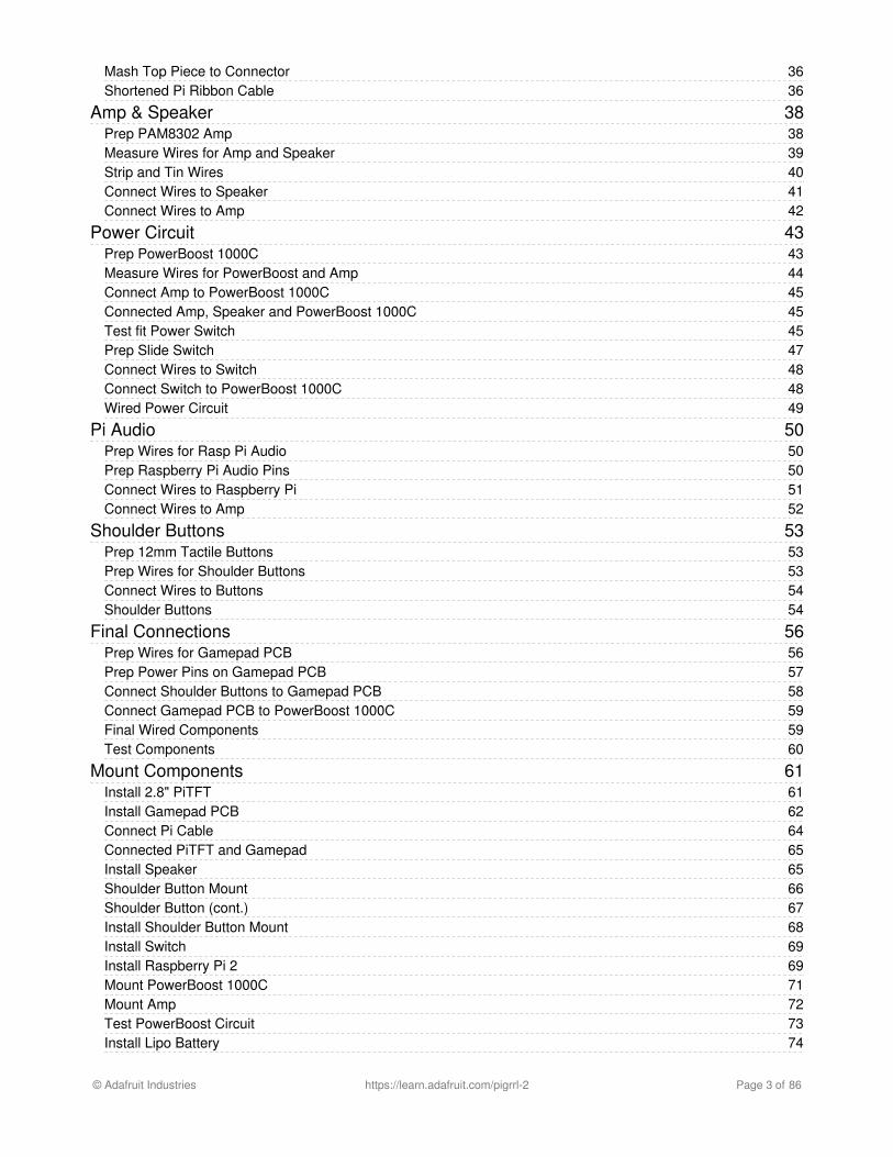
Install 6mm Tactile ButtonsInsert each button into the through-hole spots on the
gamepad PCB. Once installed, place your hand over the
buttons and bend each of the leads inward so they
"bite" onto the PCB - This will help hold them in place.
© Adafruit Industries https://learn.adafruit.com/pigrrl-2 Page 24 of 86

If you are using the elastomer buttons, they're still
possible to use, but they wont sit perfectly flat. That's
OK just make them as flat as you can!
Solder Buttons to Gamepad PCBSecure the gamepad PCB to a Panavise and solder up
the buttons. Make sure solder joints are clean like you
did on the pins of the IC box header.
© Adafruit Industries https://learn.adafruit.com/pigrrl-2 Page 25 of 86

Soldered Gamepad PCB
Here's what the soldered gamepad will look like. Clean and Shiny!
Tap Gamepad PCB Mounting Holes
Now is a good time to tap the mounting holes of the gamepad PCB. We need to create threads on each hole so that it'seasier to mount to the case. You can use a #4-40 sized tap tool, or a #4-40 machine screw to do this, just make sure tofasten as straight as you can.
© Adafruit Industries https://learn.adafruit.com/pigrrl-2 Page 26 of 86

PiTFT Display
GPIO #18 - LED Backlighting
Flip the 2.8" PiTFT display over and locate the pad with label #18. We need to cut this trace in order to properly useGPIO 18 (The Y Button is wired to this GPIO). By default, when GPIO 18 is triggered to ground, it will disable the LEDbacklighting on the display - Cutting the trace here will disable that feature.
Cut Trace #18
© Adafruit Industries https://learn.adafruit.com/pigrrl-2 Page 27 of 86

Use a hobby knife to mark in between the two pads and make sure it is deep enough to fullly break the trace.
That's pretty much all we need to do to the PiTFT display!
© Adafruit Industries https://learn.adafruit.com/pigrrl-2 Page 28 of 86

PiCable
PiCable Resizing
In this section, we'll resize the PiCable so it's more manageable once installed inside the case. Its some what optional -you can skip it but if you find space too tight when closing the case, you may want to resize the PiCable.
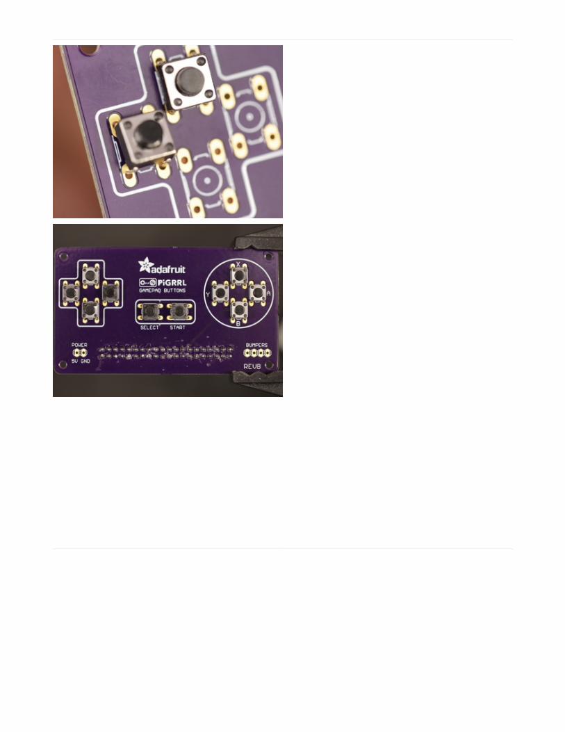
The stock ribbon cable is 152.4mm(6") in length, but I've found shortening it down to 108mm is just the right fit for thelength we need.
© Adafruit Industries https://learn.adafruit.com/pigrrl-2 Page 29 of 86
Measure, Mark and Cut Ribbon CableUse a pair of calipers or measuring tape to get the
desired length and mark the ribbon cable - Tape, marker
or otherwise.
© Adafruit Industries https://learn.adafruit.com/pigrrl-2 Page 30 of 86

Cut Cable
With the cable split in two, set aside the longer end and keep the short end handy - we need to remove the connectorfrom the end of it.
Removing ConnectorTake a close look at the bottom of the connector. You'll
see two tiny holes near each side. Now take a look at
the side. You'll see the connector has a clip that is held
in place with a notch. The goal here is to push that clip
away from the notch so we can fit the top from the
connector. You can fit something small and pointy such
as a needle into the holes and push the clip away from
the notch while pulling the top from the connector.
When the clip is free, carefully pull the top part out.
You'll need to do this for both sides.
© Adafruit Industries https://learn.adafruit.com/pigrrl-2 Page 31 of 86

DO THIS SLOWLY - Be very careful not to break the clips off!
© Adafruit Industries https://learn.adafruit.com/pigrrl-2 Page 32 of 86

Peel Cable from ConnectorWith the top removed from the connector, carefully peel
the ribbon cable from the connector. You should be left
with the top part and the female connector. You can
discard the ribbon cable.
Install Connector to Shortened RibbonCableGrab the longer piece of the ribbon cable from earlier
and lay the cut end over the top piece - The ribbon
cable should nicely fit into the grooves of the top piece.
Now grab the female connector and insert the top piece
into back onto the connector. Make sure the
arrow/triangle marking lines up with the side of the
ribbon cable with the single white colored wire. Press
the two pieces together and make sure the clips nicely
fit into the sides of the connector.
Slowly peel the ribbon cable off - If any metal bits come out, carefully push them back into the connector.
© Adafruit Industries https://learn.adafruit.com/pigrrl-2 Page 33 of 86

© Adafruit Industries https://learn.adafruit.com/pigrrl-2 Page 34 of 86

Mash Top Piece to Connector
Unless you're incredibly strong, you won't be able to press the top piece back onto the connector because it's hard topuncture the wire with the pointy teeth. The easiest way to do this is to use a rubber mallet to smash the piecestogether. I recommend doing this on a hard surface (like on the floor) while holding the connector in place. Tap the toppiece in sessions as straight as you can and be careful not to mash your fingers in the process. If all goes well, theteeth from the connector will puncture the ribbon cable and close the two pieces back together.
Shortened Pi Ribbon Cable
© Adafruit Industries https://learn.adafruit.com/pigrrl-2 Page 35 of 86

And there you have it! A shortened Raspberry Pi Ribbon Cable. Bit of a hack, I know - But it really does make closingthe case much easier in when we're all done.
© Adafruit Industries https://learn.adafruit.com/pigrrl-2 Page 36 of 86

Amp & Speaker
Prep PAM8302 AmpSecure the amp to a pair of helping third hands. Use the
tip of the soldering iron to heat up solder and apply to
the VIN, GND, A+, A–, + and – pins. This will make it
easier to solder wires to the pins.
© Adafruit Industries https://learn.adafruit.com/pigrrl-2 Page 37 of 86

Measure Wires for Amp and Speaker
We'll need two pieces of 30AWG wires to connect the speaker to the amp. We recommend using silicone-coatedstranded wire. Measure about 9cm in length for each wire. You don't have to use different colored wires, but werecommend it to help tell them apart.
© Adafruit Industries https://learn.adafruit.com/pigrrl-2 Page 38 of 86

Strip and Tin WiresUse a pair of wire strippers to remove about 4mm of
insulation from the tips of each wire. To keep the tips of
wires from fraying, use the tip of the soldering iron to
apply solder. You can bundle the tips of wires together
and use a pair of helping third hands to tin the tips at the
same time.
© Adafruit Industries https://learn.adafruit.com/pigrrl-2 Page 39 of 86

Connect Wires to SpeakerRemove the wires connected to the speaker, they're too
short. We'll need to connect the new pieces of wire we
just prepped onto the solder pads of the speaker.
Secure the speaker to the helping third hands - Since
there's a magnet on it, we can stick it to one of the
grabber arms. Reference the photo to see which is
positive (right pad) and negative (left pad). Next, slip on
a piece of heat shrink tubing to group the two wires.
© Adafruit Industries https://learn.adafruit.com/pigrrl-2 Page 40 of 86

Connect Wires to AmpSecure the amp back onto the helping third
hands. Solder the positive wire from the speaker to the
positive output pin on the amp, then, solder the negative
wire to the negative output pin. Now we can proceed to
work on the power circuit.
© Adafruit Industries https://learn.adafruit.com/pigrrl-2 Page 41 of 86

Power Circuit
Prep PowerBoost 1000C
Secure the PowerBoost to the pair of helping third hands. Apply solder to the following pins: Positive(+) out,Negative(–) out, EN, GND, G and 5V.
© Adafruit Industries https://learn.adafruit.com/pigrrl-2 Page 42 of 86

Measure Wires for PowerBoost and AmpWe'll need about 3cm in length of 30AWG wire to
connect the Amp to the PowerBoost 1000C. Use wire
strippers to remove about 4mm of insulation from each
tip and apply solder to tin them. Now secure the amp to
the helping third hands and solder the wires to the
Vin and Gnd pins.
© Adafruit Industries https://learn.adafruit.com/pigrrl-2 Page 43 of 86

Connect Amp to PowerBoost 1000CSlip on a piece of heat shrink tubing to the wires
connected to the Vin and Gnd pins. Next, secure the
PowerBoost 1000C to the helping third hands. Solder
the VIN wire from the amp to the 5V pin on the
PowerBoost. Then, solder the Gnd wire from the amp to
the G pin on the PowerBoost 1000C.
Connected Amp, Speaker and PowerBoost 1000C
Now our amplifier and speaker are wired up the PowerBoost 1000C.
Test fit Power SwitchNext up we need to connect our slide switch to the
PowerBoost 1000C. First, we should do a test fit and see
if our switch can fit into the case. Insert the switch into
the switch cutout of the bottom case. Press it all the way
through. If it's too tight, you can use a filing tool to open
it up.
© Adafruit Industries https://learn.adafruit.com/pigrrl-2 Page 44 of 86

© Adafruit Industries https://learn.adafruit.com/pigrrl-2 Page 45 of 86

Prep Slide SwitchRemove one of the legs from the slide switch. Secure
the switch to the helping third hands and apply solder to
the two remaining legs. Now we'll need two new
30AWG wires that measure abot 7cm in length. Strip
and tin the tips of each wire.
© Adafruit Industries https://learn.adafruit.com/pigrrl-2 Page 46 of 86

Connect Wires to SwitchSolder the two wires to the two leads of the slide switch.
Add pieces of heat shrink tubing to each terminal to
insulate them.
Connect Switch to PowerBoost 1000CNow we need to solder the two wires to the EN and
GND pins of the PowerBoost. The polarity doesn't
matter that much here. The switch can be installed in
your prefered position later (ie. Up position is ON, Down
position if OFF, it's up too you!).
© Adafruit Industries https://learn.adafruit.com/pigrrl-2 Page 47 of 86

Wired Power Circuit
Now we have our amp, speaker, PowerBoost and slide switch all wired up and connected. Now's a good time to take abreak or continue!
© Adafruit Industries https://learn.adafruit.com/pigrrl-2 Page 48 of 86

Pi Audio
Prep Wires for Rasp Pi Audio
To connect the amp to the Raspberry Pi 2, we'll need two wires. Cut two pieces of 30AWG wires to about 10cm inlength. Strip and tin the tips of each wire.
Prep Raspberry Pi Audio Pins
On the bottom of the Raspberry Pi 2 PCB, locate the audio jack and inspect the three pin connected to the component.
© Adafruit Industries https://learn.adafruit.com/pigrrl-2 Page 49 of 86

Take note of the two circles highlighting the pins. The left pin (blue) will connect to the negative pin on the amp, whilethe right pin (red) connects to the positive pin. The middle pin does not need to be tinned (disregard the tinning in thephoto).
Place the tip of the soldering iron over the pin and apply a small amount of solder. This will make connecting wires tothe audio amp much easier.
Connect Wires to Raspberry Pi
Solder the new wires to the pins on the bottom of the Raspberry Pi. The negative(blue) wire connects to the left pin,while the positive(ed) wire connects to the right pin.
© Adafruit Industries https://learn.adafruit.com/pigrrl-2 Page 50 of 86

Connect Wires to Amp
Solder the negative (blue) wire to the A– pin on the amp, and the positive (red) wire to the A+ pin on the amp.
Audio Connection Confusion? You may notice the audio connections in the photo above are reserved. Thisphoto is intended for the Pi 1 Model B+ (not the 2 or 3). Be sure to follow the first set of photos if you're usingthe Pi 2 or 3. If your using the Pi 1 Model B+, then reference the photo above.
© Adafruit Industries https://learn.adafruit.com/pigrrl-2 Page 51 of 86

Shoulder Buttons
Prep 12mm Tactile Buttons
Next up we need to prepare two 12mm buttons for our shoulder L and R buttons.
Start by clipping two of the four legs from each button. Use a pair of flat pliers to flatten out the legs so they point outlike in the photo. Secure the button to a pair of helping third hands and apply solder to each leg to tin them.
Prep Wires for Shoulder Buttons
© Adafruit Industries https://learn.adafruit.com/pigrrl-2 Page 52 of 86

We'll need two sets of wires (four total) to measure about 14cm in length. Strip and tin the tips from each wire andthread them through one big piece of heat shrink tubing. This will keep the wires together in a neat bundle.
Connect Wires to Buttons
Solder wires to the legs of each button - Like before, use a pair of helping third hands to assist you. Polarity doesn'tmatter too much on these buttons, but you can reference the photo.
Shoulder Buttons
© Adafruit Industries https://learn.adafruit.com/pigrrl-2 Page 53 of 86

OK, now we have our shoulder buttons prepped and ready to wire into our gamepad PCB. The next page will gothrough the final connections for our build.
© Adafruit Industries https://learn.adafruit.com/pigrrl-2 Page 54 of 86

Final Connections
Prep Wires for Gamepad PCB
Now we need to connect our gamepad PCB to the PowerBoost 1000C. We'll need two 26AWG (which is thicker thanthe 30AWG we've been using so far) that's about 14cm in length. Like before, strip and tin the ends of each wire. Then,let's slip on a long piece of heat shrink tubing to keep the two wires together.
© Adafruit Industries https://learn.adafruit.com/pigrrl-2 Page 55 of 86

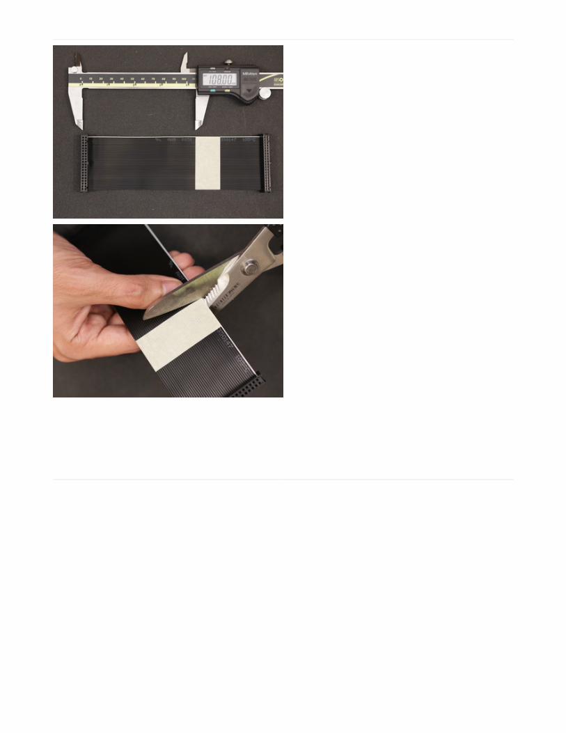
Prep Power Pins on Gamepad PCBLocate the power label on the gamepad PCB and take
note of the 5V and GND pins. Flip the gamepad PCB
over and secure it to a Panavise to hold it in place.
Apply solder to the two pins and solder in our two
26AWG wires. Use the photo to reference which wires
goes were (red right, white left).
© Adafruit Industries https://learn.adafruit.com/pigrrl-2 Page 56 of 86
Connect Shoulder Buttons to GamepadPCBLocate the bumper labeled pins on the opposite side of
the gamepad PCB. Referencing the photo, from the
bottom up, the order of pins are: L button, R button,
Ground, Ground. Once you're familiar with the pin
order, solder in the wires from the 12mm tactile buttons.
© Adafruit Industries https://learn.adafruit.com/pigrrl-2 Page 57 of 86

Connect Gamepad PCB to PowerBoost 1000C
Now we can solder in the two wires connected to the power pins of the gamepad PCB to the power output pin on thePowerBoost. The 5V wire from the gamepad connects to the positive pin on the PowerBoost, and the Ground wirefrom the gamepad connects to the negative pin on the PowerBoost.
Final Wired Components
OK, now all of our wires are connected, yay! Our components are connected and we're ready to mount them to thecase. In the next page, we'll finish up our build!
© Adafruit Industries https://learn.adafruit.com/pigrrl-2 Page 58 of 86

Test Components
Its good practice to test all of our components before we start mounting things to the enclosure. Just as a sanity check,this ensures our components and wiring is all good and working. Go ahead and insert your microSD card into theRaspberry Pi - make sure the software is already installed and loaded.
Once thats sorted, plug in the JST connector from our battery into the PowerBoost 1000C. Next, plug the Pi ribboncable into the PiTFT GPIO breakout and connect the other end to the PiGRRL Gamepad. Then, lay the PiTFT over theRaspberry Pi and press it down to connect together the GPIOs until they’re fully seated.
Now you can flip the slide switch to power on the circuit. The PiTFT should display the boot up scripts andautomatically launch RetroPi Emulationstation. Test out the DPad and buttons to see if everything works as expected.You should hear audio once a ROM is loaded. If you don’t have any loaded, reference the software page for uploadingROMs (You should be able to launch Quake from the Ports section).
If the audio isn’t working, or the buttons aren’t triggering, you’ll want to double check your wiring. If you are not surehow to use a multi-meter to check for any shorts and continuity, you may want to post up any specific issues in theAdafruit Forums, where our dedicated engineering support team can help you trouble shoot.
If everything works during your test, you should be safe to power down the Raspberry Pi and move onto the next page.
© Adafruit Industries https://learn.adafruit.com/pigrrl-2 Page 59 of 86

Mount Components
Install 2.8" PiTFTThe first component we need mount to the case is the
display screen. Before we do that, we'll need to insert
the PiTFT rubber buttons into the case. Place them over
the cutouts from the inside of the top case and press
them into place.
Now that the PiTFT button actuators are in place, lay the
PiTFT screen over the case. Line up the mounting holes
with the standoffs. Then, insert #4-40 3/8 sized machine
screws into each mounting hole and fasten them into
place. Be careful not to apply excess force, and fasten
slowly.
© Adafruit Industries https://learn.adafruit.com/pigrrl-2 Page 60 of 86

Install Gamepad PCBNext up, let's fasten #4-40 3/8 sized machine screws
into the mounting holes on the corners of the gamepad
PCB. Insert them from the top of the PCB so that they're
just barely protruding from the back side. This makes it
easier to mount it to the standoffs in the case.
Now, insert the rubber D-Pad, Action Buttons and
Pause/Start actuators into the cutouts of the top case
part. Place the gamepad PCB over the standoffs and line
them up with screws. Slowly (and carefully) fasten the
screws into the standoffs. However, DO NOT fasten
them all the way through! Only fasten them down until
they're deep enough to be lower than the height of the
case. Please reference the photo - if screws are inserted
too far, they could protrude through the surface of the
case.
DO NOT insert screws all the way through standoffs! Reference the photo to see required depth.
© Adafruit Industries https://learn.adafruit.com/pigrrl-2 Page 61 of 86

© Adafruit Industries https://learn.adafruit.com/pigrrl-2 Page 62 of 86

Connect Pi CableNext, we can install the Pi Cable to conenct the
Gamepad PCB to the PiTFT display. The orientation of
the Pi cable is important, so reference the photo and
follow the markings.
© Adafruit Industries https://learn.adafruit.com/pigrrl-2 Page 63 of 86

Connected PiTFT and Gamepad
Now our PiTFT display and Gamepad PCB are mounted to the case. Press the buttons on the PiTFT and Gamepad totest them and see they feel good. If the buttons get stuck, the gamepad isn't flush with the standoffs.
Install Speaker
Let's go ahead and pop the speaker into the case. Lay the speaker over the cavity with the grill and press it down tosnap it into place. The wire should be oriented in a position so it's not in the way of the corner standoff.
© Adafruit Industries https://learn.adafruit.com/pigrrl-2 Page 64 of 86

Shoulder Button MountNext up we need to mount our two shoulder buttons to
the shoulder mounting piece. To do that, we can use
adhesives such as E600 or hotglue - But I've found
using mounting tack works just fine (plus, it makes it
adjustable if we don't position it correctly the first time
around). Add the tack to the back of the 12mm button
and position them over the two recessed square spots
on the mounting part. Press them down to stick them
into place.
© Adafruit Industries https://learn.adafruit.com/pigrrl-2 Page 65 of 86

Shoulder Button (cont.)Fasten four #2-56 3/8 into the standoffs of the shoulder
mount. Screw them in until the barely protrude the
standoff - this is going to make it easier to mount it to
the case. Next, insert the rubber shoulder button
actuator into the cutout of the bottom case part.
© Adafruit Industries https://learn.adafruit.com/pigrrl-2 Page 66 of 86

Install Shoulder Button MountPlace the shoulder mount over the standoffs on the
bottom case. Make sure the screws line up with the
standoffs - they're position / orientation specific. Once
they're lined up, carefully fasten the screws down. Here,
you can fasten them all the way.
© Adafruit Industries https://learn.adafruit.com/pigrrl-2 Page 67 of 86

Install Switch
Now if a good time to insert the slide switch into the bottom case. Take note of the OFF position of the slide and installit to your liking (I prefer down is OFF, up is ON).
Install Raspberry Pi 2Next up, lets mount the Pi to the bottom case. First, let's
fasten #4-40 3/8 sized machine screws to the two
mount holes on the back of the bottom case part. Like
the previous mounting standoffs, fasten the screws so
they're just barely protuding through the top of the
standoffs. Then, lay the Pi over the standoffs and line up
the screws with the mounting holes. Once in place,
fasten the screws all the way until they're flush with the
surface of the case.
© Adafruit Industries https://learn.adafruit.com/pigrrl-2 Page 68 of 86

© Adafruit Industries https://learn.adafruit.com/pigrrl-2 Page 69 of 86

Mount PowerBoost 1000CWe'll need two #4-40 3/8 machine screws to install the
PowerBoost to the case. Fasten the screws to the two
mounting holes of the PowerBoost - This will create
threads. Once they're made, lay the PowerBoost over
the standoffs (close to the center bottom). Hold the PCB
in place while fastening the screws to the standoffs.
Don't fasten these screws all the way through, just deep
enough they go past the heigh of the case - similar to
the other components.
© Adafruit Industries https://learn.adafruit.com/pigrrl-2 Page 70 of 86

Mount AmpInsert and fasten a single #4-40 3/8 machine screw into
the mounting hole of the amp PCB (should be the hole
closest to the Adafruit logo) - This will help create the
screw threads. Then, place the PCB over the standoffs
and hole it down to fasten the screw into the standoff.
© Adafruit Industries https://learn.adafruit.com/pigrrl-2 Page 71 of 86

Test PowerBoost Circuit
Grab the lipo battery and plug in the JST connector to the JST port on the PowerBoost 1000C. Flip the slide switch on,and see if the circuit works! The blue LED indicates the battery is charged and the circuit is powered on.
If the LED doesn't light up, you either have a defective PowerBoost, or a short. You'll have to double check your wiringfor short using a a multi-meter. If you have any issues or questions, please post it on support forumsat http://forums.adafruit.com/ (https://adafru.it/forums)
© Adafruit Industries https://learn.adafruit.com/pigrrl-2 Page 72 of 86

Install Lipo BatteryNow we can install the 2000mAh lipo battery. A good
spot for it is right behind the PiTFT display. To keep it in
place, we can use a piece of gaffers tape. Try to keep it
up closely against PiCable. Position it like in the photo,
closer to the right side to avoid intersecting with some
of the components from the Pi.
Almost Done!
In the next page, we'll close up the case and finish the build!
© Adafruit Industries https://learn.adafruit.com/pigrrl-2 Page 73 of 86

Close It Up!
Join PartsNow its time to close it all up. Before that, make sure all
of the wires are inside the case. Wires should be neaty
tucked and away of kinking from any of the
components. Bring the top and bottom parts together
and press the bottom part together. They should snap
together. Then, inspect the edges and see if everything
is in place - no wires hanging out. If it looks good, start
pressing the top area close together - Slowly. If you can't
squeeze the top together, the battery could be in the
way - be sure to check that and ensure its not in the way
of any of the components.
© Adafruit Industries https://learn.adafruit.com/pigrrl-2 Page 74 of 86

Screw Bottom PortionThere's two spots on the bottom that feature counter
bore standoffs - insert a #2-56 3/8 machine screw and
fasten them all the way. This will keep the bottom from
coming part.
© Adafruit Industries https://learn.adafruit.com/pigrrl-2 Page 75 of 86

Insert microSD Card
Lastly, insert the microSD card if you haven't already. You should have already burnt the PiGRRL image to the SD card.If not, go ahead and do that now!
Completed Build!
Hazzah! The PiGRRL 2 game console is finally finished and ready to play! Turn it on and RetroPie / Emulationstationshould automatically boot. The buttons are premapped to the expected controls. Reference the Software page foruploading ROMs and remapping controls.
Share Your Creation With Us!
If you built PiGRRL 2, we'd love to see it and share it with the community! Post a make on the thingiverse project page,share it on Instagram or twitter with hashtag #PiGRRL2.
© Adafruit Industries https://learn.adafruit.com/pigrrl-2 Page 76 of 86

Trouble ShootingButtons don't work, things are very weird
Make sure you didn't plug the Pi cable in backwards, you can use a multimeter to check that these voltages arecorrect when the Pi is powered:
Audio Issues
Are you hearing a strange sound when powering up the Pi? The battery might be in a bad spot where it's causinginterference noise with the audio jack. If you remove the mounting screws from the Pi on the back of the bottom case,you can separate the two parts while it's still powered.
© Adafruit Industries https://learn.adafruit.com/pigrrl-2 Page 77 of 86

Once they're separated, reposition the battery and listen carefully to the noise. Position the battery in a spot where thenoise is less prominent and mount it in place with tape or mounting tack.
Another option you can try is to adjust the pot on the sound amp. Lowering the gain may fix the sound interferencewhen repositioning the battery doesn't work.
The best location for the battery I've found is directly tucked inbetween the Raspberry Pi and the PiTFT display.
No Audio
Retropie has sound options built into the software. It may be muted or set to really low. To adjust it, press the "Start"button to bring up the Menu. Then, use the D-Pad to highlight “Sound Settings”. Use the “A” button to select and D-Pad to increase volume. Press the “B” button to exit.
Pressing Button Turns Off Screen
If the PiTFT display turns black when you press one of the gamepad buttons, the trace that controls the backlightingmight need to be cut deeper. The label #18 on the back of the PiTFT is active by default - triggering it turns the displayoff. Make sure this trace is cut to deactivate this feature.
Button on pin #18 doesn't work
You didn't cut the trace on the #18 pad, make sure to do that
PiTFT Shows Only White Screen
If the PiTFT display only display a white screen, chances are the img wasn't properly burnt to the SDcard. Be sure tofollow the steps Easy SD Card Setup (https://adafru.it/aMW) guide to correctly burn the image.
Custom Mute Function
© Adafruit Industries https://learn.adafruit.com/pigrrl-2 Page 78 of 86

If you're interested in making one of the PiTFT buttons mute the audio, Martin O'Hanlon made a function.
https://adafru.it/kUb
https://adafru.it/kUb
Better Sound quality
A suggestion from the forums (https://adafru.it/ikE)!
1)Wrap the battery in copper tape and then electrical tape. Then you solder a wire from the ground of the audiocircuit to the copper. It helps to solder to a random piece and then stick it to the battery so you're not soldering onthe battery itself as it's dangerous.
2)Buy tiny ferrite beads and put them around the speaker wires. Ferrite beads provide EMI shielding and puttingthem around the speaker wires worked like a charm.
Issues, Problems, Need Help?
If you encounter any technical problems with the Raspberry Pi software, components or otherwise, please post up yourissue, including photos of your wiring on the Adafruit Forums. Our support team will be able to assist you there.
https://adafru.it/kZb
https://adafru.it/kZb
© Adafruit Industries https://learn.adafruit.com/pigrrl-2 Page 79 of 86

Extras
Safely Shutdown via Tactile Switch
Its a good idea to safely turn off your Pi with a good sudo shutdown -h now but that often means pulling out akeyboard or connecting to the console. With our kernel we added a cool module that will let you turn any GPIO into apower button. Since there's a couple of tactile switches right there on the front, lets turn one into a power button. Pressonce to properly turn off the pi, press again to start it up. Isn't that nice?
https://adafru.it/ird
https://adafru.it/ird
© Adafruit Industries https://learn.adafruit.com/pigrrl-2 Page 80 of 86

Troubleshooting RetroPie and retrogameThis page documents the most common pitfalls encountered when making retro gaming projects, offering somesolutions and where to turn for further help.
There are some things we can fix and some we can’t…we’re not involved in RetroPie’s development, for example…butwe’ll try to point you in the right direction.
Most of the following troubleshooting steps will require a USB keyboard attached. Some require a networkconnection.
retrogame Related Troubleshooting
retrogame is our software that converts GPIO button actions into keyboard events. These are the problems we’re bestequipped to fix.
Some common things to check for any retrogame installation:
Confirm button/joystick wires go to the correct pins and to ground. A multimeter with a continuity beep function ishelpful for testing.The retrogame configuration file (/boot/retrogame.cfg) uses Broadcom pin numbers…these are not sequentialalong the GPIO header pins. This site has a nice reference chart (https://adafru.it/uFH) (use the “BCM” numbers).Earlier versions of retrogame didn’t use a configuration file…you had to edit and compile the source code. That’sjust horrible. If you’re running an early version like that, this would be a good time to upgrade. See the InstallingRetrogame (https://adafru.it/sct) page.
Some of my buttons/controls aren’t working!
Check connections and configuration file pin numbers as explained above. (If some controls are responding,that’s an encouraging start…it at least means the code is running.)The key codes generated by retrogame might not be assigned to EmulationStation’s keyboard inputs; one orthe other will need to be changed. Either edit /boot/retrogame.cfg, or, from the EmulationStation main screen,press Start to access the main menu, then select “Configure Input” and proceed through each of the controls.
NONE of my buttons/controls are working!
Confirm that retrogame is actually running…either exit to the command line (F4) or log in using ssh, then use“ps -ef | grep retrogame” to check. If you used our installer script or one of our ready-made SD card images, itshould be started automatically on boot (added to /etc/rc.local).Confirm that the file “/etc/udev/rules.d/10-retrogame.rules” exists. Our installer script creates this file, but if youinstalled retrogame manually or from source, it may have been overlooked.
My controls only work if there’s also a USB keyboard plugged in!
Confirm that the file “/etc/udev/rules.d/10-retrogame.rules” exists. Our installer script creates this file, but if youinstalled retrogame manually or from source, it may have been overlooked.
Retrogame doesn’t work with my optical buttons!
Unfortunately, yes. retrogame only works with “passive” switches between a GPIO pin and ground (logiclow=pressed). It won’t work with switches that have the opposite logic level (high=pressed).
I ran Adafruit’s retrogame installer script and rebooted, and now the keyboard and network are unresponsive!
This can happen if you’re running an early Raspberry Pi (Model A or B) with the 26-pin GPIO header and select the
© Adafruit Industries https://learn.adafruit.com/pigrrl-2 Page 81 of 86

“Six buttons + joystick” option in the retrogame installer. That particular configuration is set up for our Arcade Packand newer (40 pin) Raspberry Pi boards. Some of the pin numbers referenced don’t exist on the older 26-pinheader and lead to trouble.
If this happens to you, not to worry. Power off the Pi and insert the SD card in a reader on a PC or Mac. Look for afile called retrogame.cfg…edit this file and change the pin numbers to match your specific controller wiring.
RetroPie Related Troubleshooting
RetroPie provides the actual emulation software and a nice user interface. As this is third-party code, the “depth” ofproblems we can troubleshoot is more limited, but here are some of the common issues we’ve seen and how toresolve them…
My controls work in the EmulationStation UI, but not in one or more specific emulators!
This can happen with certain emulators (usually older or more esoteric ones) that don’t use the libretro library.Among other things, libretro allows the global controller configuration to be used everywhere. There are a couple ofworkarounds that might help, but no guarantees…
You can rummage around in /opt/retropie/configs and look for a configuration file specific to theproblem emulator, then edit its keyboard layout to match your controls. The format of this file, if one evenexists, is likely specific to that one emulator, so you’ll need to do some research (Google search, etc.), it’s notsomething we can help out with.You can try hunting for an alternate emulator based on libretro, if there’s one available (see “Installing RetroPiePackages” below).
The ROM files I have worked in a different emulator before, but aren’t working in RetroPie!
This can happen if the ROM file format changes between versions of an emulator, or if two emulators for the samesystem use different formats.
Do some research (Google search, etc.) to see if this is the case. It’s possible there may be utilities to convertamong different ROM formats.Try installing an alternate emulator, if there’s one available (see “Installing RetroPie Packages” below).
A few emulators may require a “BIOS file” in order to function, but it’s not included with the software for legalreasons. This is something you’ll have to research and track down.
Installing RetroPie Packages
To add support for a system not present in RetroPie by
default, or to add an alternate emulator program for an
existing system, select “RetroPie Setup” from the
RetroPie menu. This brings up a text-menu-based
interface and will require a USB keyboard to navigate.
Select “Manage packages” and then one of the core,
main, optional or experimental selections…you’ll
probably want to navigate through each of them to see
what’s available, keeping in mind that each successive
category might be a little rougher around the edges.
Your best bet are packages whose names begin with
© Adafruit Industries https://learn.adafruit.com/pigrrl-2 Page 82 of 86

“lr-”. This means they’re built using libretro and the
control inputs should already work with what you have!
Other packages may require their own manual controller
setup, which can be a real nuisance.
When asked, select “Install from binary.” The sourceoption takes much longer and won’t provide any benefit
for the average user…only attempt that if you know you
need absolutely bleeding-edge code.
It’s totally valid to install multiple emulator packages that
handle the same type of system. Each might have
different performance or compatibility benefits, so it’s
worth testing your options. See “Accessing Alternate
Emulators” below.
© Adafruit Industries https://learn.adafruit.com/pigrrl-2 Page 83 of 86

Accessing Alternate Emulators
© Adafruit Industries https://learn.adafruit.com/pigrrl-2 Page 84 of 86

When you launch a game, you’ll briefly see this
nondescript launching message. You have a couple of
seconds to hit a button or key…
The first option in this configuration menu lets you
select a different emulator package for a given system
type…or even on an individual ROM-by-ROM basis, if
different games benefit from different emulation
software.
Test it out with. If you don’t like the results, next time
you launch that game you can access the configuration
menu again and restore the original selection.
More RetroPie Help
For issues not covered above, the best sources for RetroPie-specific help are the official documentation and forum onthe RetroPie web site:
RetroPie Documentation (https://adafru.it/uFI)
RetroPie Forum (https://adafru.it/uFJ)
© Adafruit Industries https://learn.adafruit.com/pigrrl-2 Page 85 of 86