e3 and e3 plus solid-state overload relay - quick...
TRANSCRIPT

E3 and E3 Plus Solid-State Overload Relay
Quick Start Guide
(Bulletins 193 and 592)
www.klinkmann.com6 / 2011
2
Publication 193-QR003B-EN-P - October 2009
Important User InformationBecause of the variety of uses for the products described in this publication, those responsible for the application and use of this control equipment must satisfy themselves that all necessary steps have been taken to assure that each application and use meets all performance and safety requirements, including any applicable laws, regulations, codes, and standards.
The illustrations, charts, sample programs and layout examples shown in this guide are intended solely for purposes of example. Since there are many variables and requirements associated with any particular installation, Rockwell Automation does not assume responsibility or liability (to include intellectual property liability) for actual use based upon the examples shown in this publication.
Rockwell Automation publication SGI-1.1, Safety Guidelines for the Application, Installation and Maintenance of Solid-State Control (available from your local Allen-Bradley distributor), describes some important differences between solid-state equipment and electromechanical devices that should be taken into consideration when applying products such as those described in this publication.
Reproduction of the contents of this copyrighted publication, in whole or part, without written permission of Rockwell Automation, is prohibited.
ATTENTION
!This guide does not replace the User Manual, publication 193-UM002_-EN-P, and is intended for qualified service personnel responsible for setting up and servicing these devices. You must have previous experience with and a basic understanding of electrical terminology, configuration procedures, required equipment, and safety precautions. The user manual can be downloaded from http://literature.rockwellautomation.com.
www.klinkmann.com6 / 2011
3
Publication 193-QR003B-EN-P - October 2009
General PrecautionsIn addition to the specific precautions listed throughout this manual, the following general statements must be observed.
IMPORTANT The purpose of this publication is to serve as a guide for proper installation. The National Electrical Code and any other governing regional or local code overrules the information in this publication.A hazard of personal injury/equipment damage exists if codes are ignored during installation. Rockwell Automation cannot assume responsibility for the compliance or proper installation of the E3 Overload Relay or associated equipment.
IMPORTANT Only personnel familiar with the E3 Overload Relay and associated machinery should plan to install, start up, and maintain the system. Failure to comply may result in personal injury/equipment damage.
IMPORTANT An incorrectly applied or installed E3 Overload Relay can result in damage to the components or reduction in product life. Wiring or application errors, such as incorrectly configuring the FLA Setting, supplying incorrect or inadequate DeviceNet supply voltage, connecting an external supply voltage to the input or thermistor terminals, or operating/storing in excessive ambient temperatures may result in malfunction of the E3 Overload Relay.
IMPORTANT The E3 Overload Relay contains ESD (electrostatic discharge) sensitive parts and assemblies. Static control precautions are required when installing, testing, servicing, or repairing this assembly. Component damage may result if ESD control procedures are not followed. If you are not familiar with static control procedures, refer to Allen-Bradley publication 8200-4.5.2, Guarding Against Electrostatic Damage, or any other applicable ESD protection handbook.
www.klinkmann.com6 / 2011
4
Publication 193-QR003B-EN-P - October 2009
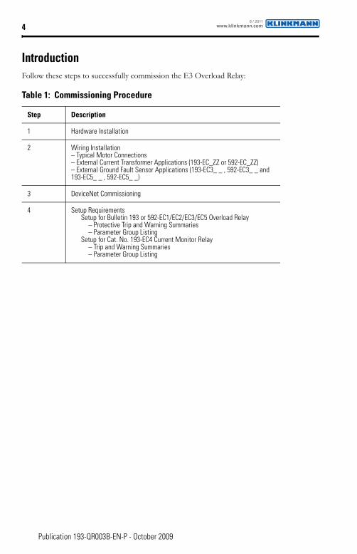
IntroductionFollow these steps to successfully commission the E3 Overload Relay:
Table 1: Commissioning Procedure
Step Description
1 Hardware Installation
2 Wiring Installation– Typical Motor Connections– External Current Transformer Applications (193-EC_ZZ or 592-EC_ZZ)– External Ground Fault Sensor Applications (193-EC3_ _ , 592-EC3_ _ and 193-EC5_ _ , 592-EC5_ _)
3 DeviceNet Commissioning
4 Setup RequirementsSetup for Bulletin 193 or 592-EC1/EC2/EC3/EC5 Overload Relay
– Protective Trip and Warning Summaries– Parameter Group Listing
Setup for Cat. No. 193-EC4 Current Monitor Relay– Trip and Warning Summaries– Parameter Group Listing
www.klinkmann.com6 / 2011
5
Publication 193-QR003B-EN-P - October 2009
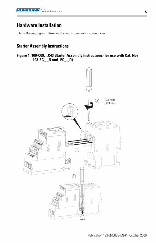
Hardware InstallationThe following figures illustrate the starter assembly instructions.
Starter Assembly Instructions
Figure 1: 100-C09…C43 Starter Assembly Instructions (for use with Cat. Nos. 193-EC_ _B and -EC_ _D)
1
2
CLICK
3
22 lb-in.
www.klinkmann.com6 / 2011
6
Publication 193-QR003B-EN-P - October 2009
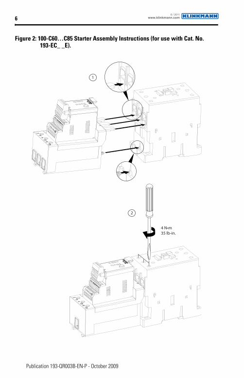
Figure 2: 100-C60…C85 Starter Assembly Instructions (for use with Cat. No. 193-EC_ _E).
1
2
35 lb-in.
www.klinkmann.com6 / 2011
7
Publication 193-QR003B-EN-P - October 2009
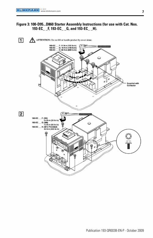
Figure 3: 100-D95...D860 Starter Assembly Instructions (for use with Cat. Nos. 193-EC_ _F, 193-EC_ _G, and 193-EC_ _H).
www.klinkmann.com6 / 2011
8
Publication 193-QR003B-EN-P - October 2009
Wiring Installation
Typical Motor ConnectionsRefer to the product nameplate or user manual for power lug termination information including:
• Terminal wire size and torque specifications• Maximum wire lengths• Lug kit catalog numbers (108…1250 A)
For reliable input signal processing, input wiring should be routed in raceways separate from power cabling.
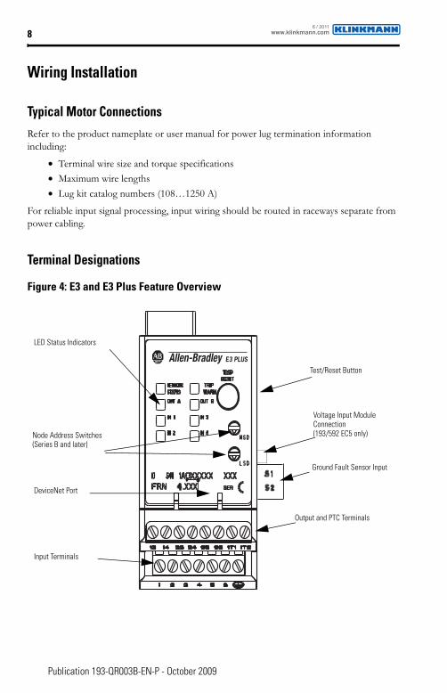
Terminal Designations
Figure 4: E3 and E3 Plus Feature Overview
E3 PLUS
LED Status Indicators
DeviceNet Port
Input Terminals
Test/Reset Button
Node Address Switches (Series B and later)
Output and PTC Terminals
Ground Fault Sensor Input
Voltage Input Module Connection(193/592 EC5 only)
www.klinkmann.com6 / 2011
9
Publication 193-QR003B-EN-P - October 2009
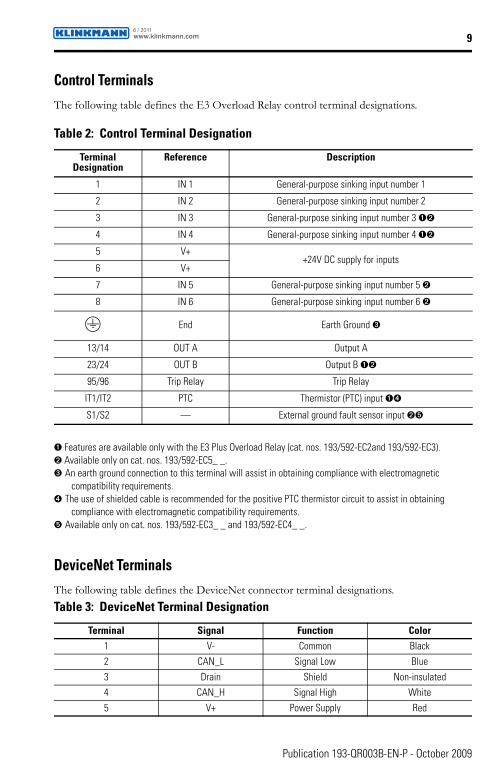
Control TerminalsThe following table defines the E3 Overload Relay control terminal designations.
➊ Features are available only with the E3 Plus Overload Relay (cat. nos. 193/592-EC2and 193/592-EC3).➋ Available only on cat. nos. 193/592-EC5_ _.➌ An earth ground connection to this terminal will assist in obtaining compliance with electromagnetic
compatibility requirements.➍ The use of shielded cable is recommended for the positive PTC thermistor circuit to assist in obtaining
compliance with electromagnetic compatibility requirements.➎ Available only on cat. nos. 193/592-EC3_ _ and 193/592-EC4_ _.
DeviceNet TerminalsThe following table defines the DeviceNet connector terminal designations.
Table 2: Control Terminal Designation
Terminal Designation
Reference Description
1 IN 1 General-purpose sinking input number 1
2 IN 2 General-purpose sinking input number 2
3 IN 3 General-purpose sinking input number 3 ➊➋
4 IN 4 General-purpose sinking input number 4 ➊➋
5 V++24V DC supply for inputs
6 V+
7 IN 5 General-purpose sinking input number 5 ➋
8 IN 6 General-purpose sinking input number 6 ➋
End Earth Ground ➌
13/14 OUT A Output A
23/24 OUT B Output B ➊➋
95/96 Trip Relay Trip Relay
IT1/IT2 PTC Thermistor (PTC) input ➊➍
S1/S2 — External ground fault sensor input ➋➎
Table 3: DeviceNet Terminal Designation
Terminal Signal Function Color1 V- Common Black
2 CAN_L Signal Low Blue
3 Drain Shield Non-insulated
4 CAN_H Signal High White
5 V+ Power Supply Red
www.klinkmann.com6 / 2011
10
Publication 193-QR003B-EN-P - October 2009
GroundingThe following grounding recommendations are provided to ensure electromagnetic compatibility compliance during installation:
• The earth ground terminal of the E3 Overload Relay shall be connected to a solid earth ground via a low-impedance connection
• Installations employing an external ground fault sensor shall ground the cable shield at the sensor with no connection made at the E3 Plus Overload Relay
• The PTC thermistor cable shield shall be grounded at the E3 Plus Overload Relay with no connection made at the opposite end
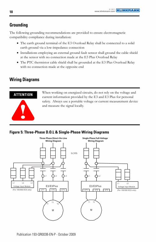
Wiring Diagrams
Figure 5: Three-Phase D.O.L & Single-Phase Wiring Diagrams
ATTENTION
!When working on energized circuits, do not rely on the voltage and current information provided by the E3 and E3 Plus for personal safety. Always use a portable voltage or current measurement device and measure the signal locally.
E3/E3Plus
L 1 L 2 L 3
2 /T 1 4 /T 2 6 /T 3
E3/E3Plus
L 1 L 2 L 3
2 /T 1 4 /T 2 6 /T 3
L1
2 /T 1 4 /T 2 6 /T 32 /T 1 4 /T 2 6 /T 32/T1 4/T2 6/T3
M
T1
E3/E3Plus
L1
2/T1 4/T2 6/T3
M
T1T2
T3
S.C.P.D.
Three-Phase Direct-On-LineWiring Diagram
Single-Phase Full-VoltageWiring Diagram
T2
L2 L3 L2
E3/E3PlusL1 L2 L3
Voltage Input Module
(For 193/592-EC5 only)
L1 L2
Voltage Input Module
(For 193/592-EC5 only)
www.klinkmann.com6 / 2011
11
Publication 193-QR003B-EN-P - October 2009
External Current Transformer Application (Cat. No. 193-EC_ZZ)E3 and E3 Plus Overload Relays (Cat. No. 193-EC_ZZ) are designed for use with separately mounted, customer-supplied current transformers (CTs) as required in higher-current applications. The FLA setting range is 9…5000 A for these units, with a legal setting range per the user’s manual. Parameter 78, CT Ratio, is provided for setting the current transformer ratio to be installed.
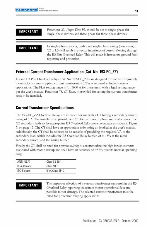
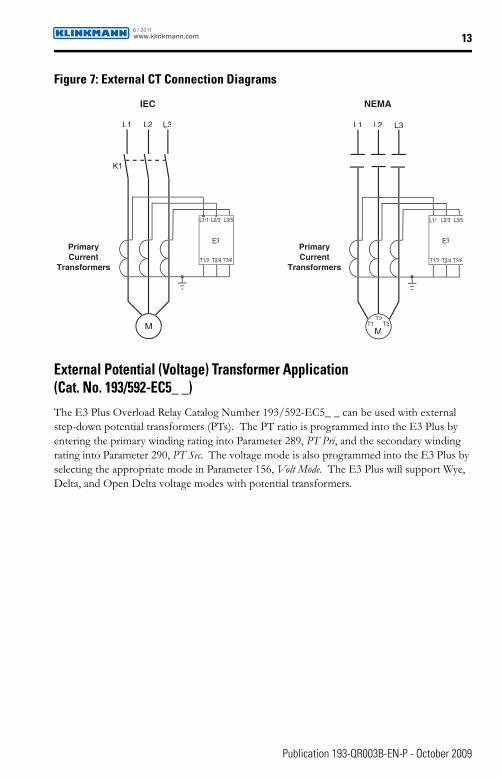
Current Transformer SpecificationsThe 193-EC_ZZ Overload Relays are intended for use with a CT having a secondary current rating of 5 A. The installer shall provide one CT for each motor phase and shall connect the CT secondary leads to the appropriate E3 Overload Relay power terminals as shown in Figure 7: on page 13. The CT shall have an appropriate ratio rating as detailed in the user’s manual. Additionally, the CT shall be selected to be capable of providing the required VA to the secondary load, which includes the E3 Overload Relay burden of 0.1 VA at the rated secondary current and the wiring burden.
Finally, the CT shall be rated for protective relaying to accommodate the high inrush currents associated with motor startup and shall have an accuracy of ≤±2% over its normal operating range.
IMPORTANT Parameter 27, Single/Three Ph, should be set to single-phase for single-phase devices and three-phase for three-phase devices.
IMPORTANT In single-phase devices, traditional single-phase wiring (connecting T2 to L3) will result in a vector imbalance of current flowing through the E3 Plus Overload Relay. This will result in inaccurate ground fault reporting and protection.
ANSI (USA) Class C5 B0.1
CSA (Canada) Class 10L5
IEC (Europe) 5 VA Class 5P10
IMPORTANT The improper selection of a current transformer can result in the E3 Overload Relay reporting inaccurate motor operational data and possible motor damage. The selected current transformer must be rated for protective relaying applications.
www.klinkmann.com6 / 2011
12
Publication 193-QR003B-EN-P - October 2009
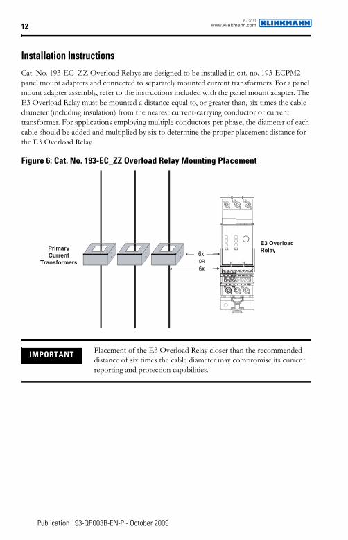
Installation InstructionsCat. No. 193-EC_ZZ Overload Relays are designed to be installed in cat. no. 193-ECPM2 panel mount adapters and connected to separately mounted current transformers. For a panel mount adapter assembly, refer to the instructions included with the panel mount adapter. The E3 Overload Relay must be mounted a distance equal to, or greater than, six times the cable diameter (including insulation) from the nearest current-carrying conductor or current transformer. For applications employing multiple conductors per phase, the diameter of each cable should be added and multiplied by six to determine the proper placement distance for the E3 Overload Relay.
Figure 6: Cat. No. 193-EC_ZZ Overload Relay Mounting Placement
IMPORTANT Placement of the E3 Overload Relay closer than the recommended distance of six times the cable diameter may compromise its current reporting and protection capabilities.
6x
6xOR
PrimaryCurrent
Transformers
E3 OverloadRelay
www.klinkmann.com6 / 2011
13
Publication 193-QR003B-EN-P - October 2009
Figure 7: External CT Connection Diagrams
External Potential (Voltage) Transformer Application (Cat. No. 193/592-EC5_ _)The E3 Plus Overload Relay Catalog Number 193/592-EC5_ _ can be used with external step-down potential transformers (PTs). The PT ratio is programmed into the E3 Plus by entering the primary winding rating into Parameter 289, PT Pri, and the secondary winding rating into Parameter 290, PT Sec. The voltage mode is also programmed into the E3 Plus by selecting the appropriate mode in Parameter 156, Volt Mode. The E3 Plus will support Wye, Delta, and Open Delta voltage modes with potential transformers.
IEC NEMA
L1 L2 L3 L1 L2 L3
E3 E3
M M
K1
T1/2
T1T2
T3
T2/4 T3/6T
L1/1 L2/3 L3/5L
T1/2 T2/4 T3/6
L1/1 L2/3 L3/5
PrimaryCurrent
Transformers
PrimaryCurrent
Transformers
www.klinkmann.com6 / 2011

14
Publication 193-QR003B-EN-P - October 2009
Figure 8: External PT Connection Diagrams
Load
L1 L2 L3
Line
L1 L2 L3
Delta Connection with PTs
Load
L1 L2 L3
Line
N/GND
L1 L2 L3
Wye Connection with PTs
Load
L1 L2 L3
Line
L1 L2 L3
Open Delta Connection with PTs
www.klinkmann.com6 / 2011

15
Publication 193-QR003B-EN-P - October 2009
External Ground Fault Sensor Application(Cat. Nos. 193/592-EC3_ _, 193/592-EC4_ _, and 193/592-EC5_ _)Cat. Nos. 193/592-EC3_ _, 193/592-EC4_ _, and 193/592-EC5_ _ E3 Plus Overload Relays are intended to provide ground fault protection when used with the cat. no. 193-CBCT_ external ground fault (core balance) sensor. The ground fault sensor mounts separately from the E3 Plus Overload Relay and must be placed within three meters of the relay. The customer-supplied cable for wiring the ground fault sensor to the E3 Plus Overload Relay should meet the specifications outlined in Table 1.9 on page 15.
Power Cable Installation Instructions
1. All power cables (including the neutral when used) must pass through the sensor window. The equipment ground conductor (the conductor used to carry the non-current-carrying metal parts of equipment, as defined by Article 100 of the NEC), must not pass through the sensor window.
2. The power cables through the sensor window should be straight, tightly bundled, centered in the window, and perpendicular to the sensor for a length equal to, or greater than, six times the cable diameter (including insulation) from the sensor.
3. All other conductors with available currents in excess of 1,000 A should be placed a distance equal to, or greater than, six times the cable diameter (including insulation) from the sensor.
4. The power cables of the branch circuit to be protected by the E3 Plus Overload Relay must not be grounded on the load side of the ground fault sensor.
5. If the power cables are enclosed in a conducting jacket, the jacket must be grounded on the line side of the sensor. The jacket must not pass through the sensor window, but must be cut at the window and joined with a conductor that passes outside the sensor window.
6. The power system may be solidly grounded or grounded through an impedance at its source as long as the impedance allows a magnitude of fault current to flow that is within the 1…5 A operational range of the E3 Plus Overload Relay (193/592-EC2_ _) or the 20 mA…5 A operational range of the E3 Plus Overload Relay (193/592-EC3_ _, 193/592-EC4_ _, and 193/592-EC5_ _).
Table 1.9 Ground Fault Sensor Terminals (S1 and S2)
Wire type Shielded, twisted pair
Cross section 0.2…4.0 mm2 (#24…12 AWG)
Torque 0.55 N•m (5 lb-in.)
www.klinkmann.com6 / 2011
16
Publication 193-QR003B-EN-P - October 2009
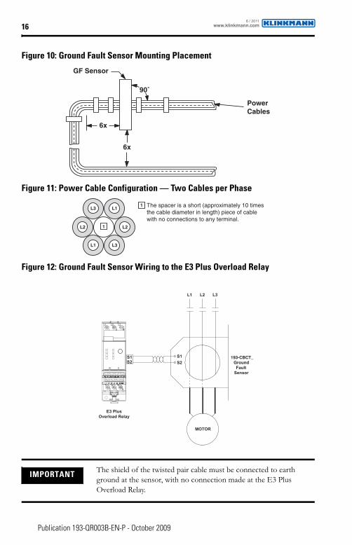
Figure 10: Ground Fault Sensor Mounting Placement
Figure 11: Power Cable Configuration — Two Cables per Phase
Figure 12: Ground Fault Sensor Wiring to the E3 Plus Overload Relay
IMPORTANT The shield of the twisted pair cable must be connected to earth ground at the sensor, with no connection made at the E3 Plus Overload Relay.
PowerCables
GF Sensor
6x
6x
90˚
L1
L2 L2
L3
L3 L1
1
1 The spacer is a short (approximately 10 times the cable diameter in length) piece of cable with no connections to any terminal.
MOTOR
L1 L2 L3
S1
S2S1S2
193-CBCT_Ground
FaultSensor
E3 PlusOverload Relay
www.klinkmann.com6 / 2011

17
Publication 193-QR003B-EN-P - October 2009
DeviceNet Node Commissioning
OverviewE3 Overload Relays are shipped with a default software node address (MAC ID) setting of 63 and the data rate set to Autobaud. Each device on a DeviceNet network must have a unique node address which can be set to a value from 0…63.
Keep in mind, most DeviceNet systems use address 0 for the master device (scanner) and node address 63 should be left vacant for introduction of new slave devices. The node address and data rate for series B or later, E3 Overload Relays can be changed using software or by setting the hardware switches that reside on the front of each unit. While both methods yield the same result, it is good practice to choose one method and deploy it throughout the system.
IMPORTANT The following recommendations are intended to ensure a trouble-free startup and operation:
1. Use the node commissioning tool in RSNetWorx or the DeviceNet configuration terminal (cat. no. 193-DNCT) when modifying the E3 node address. Do not use the General tab found in the product window in RSNetWorx. The node commissioning tool ensures the device goes through a hard reset and requires the user to upload the most current parameter information from the device prior to making configuration changes.
2. Ensure you have the most current configuration information prior to saving an RSNetWorx configuration file.
3. If you intend to employ the ADR function of the DeviceNet scanner, ensure the device configuration is as you intend it BEFORE saving it to memory.
4. Be aware the Restore Device Defaults button in RSNetWorx will reset the E3 Overload Relay node address setting to 63. For Series B or later devices, the hardware node address switches take precedence over the software node address setting.
www.klinkmann.com6 / 2011
18
Publication 193-QR003B-EN-P - October 2009
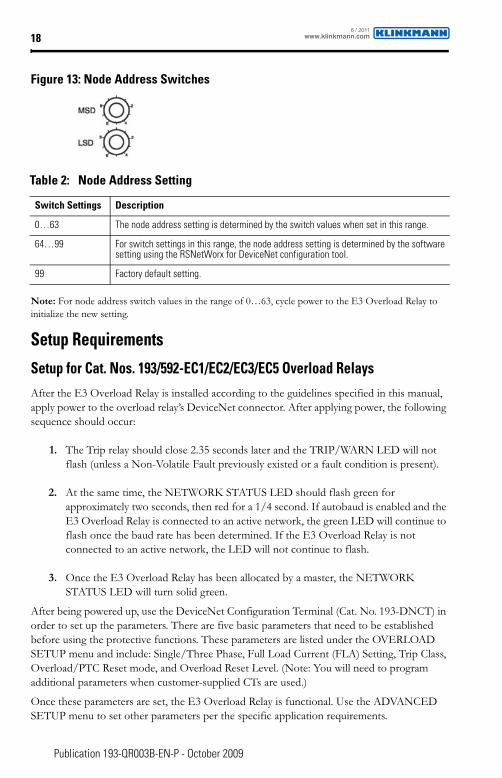
Figure 13: Node Address Switches
Note: For node address switch values in the range of 0…63, cycle power to the E3 Overload Relay to initialize the new setting.
Setup Requirements
Setup for Cat. Nos. 193/592-EC1/EC2/EC3/EC5 Overload RelaysAfter the E3 Overload Relay is installed according to the guidelines specified in this manual, apply power to the overload relay’s DeviceNet connector. After applying power, the following sequence should occur:
1. The Trip relay should close 2.35 seconds later and the TRIP/WARN LED will not flash (unless a Non-Volatile Fault previously existed or a fault condition is present).
2. At the same time, the NETWORK STATUS LED should flash green for approximately two seconds, then red for a 1/4 second. If autobaud is enabled and the E3 Overload Relay is connected to an active network, the green LED will continue to flash once the baud rate has been determined. If the E3 Overload Relay is not connected to an active network, the LED will not continue to flash.
3. Once the E3 Overload Relay has been allocated by a master, the NETWORK STATUS LED will turn solid green.
After being powered up, use the DeviceNet Configuration Terminal (Cat. No. 193-DNCT) in order to set up the parameters. There are five basic parameters that need to be established before using the protective functions. These parameters are listed under the OVERLOAD SETUP menu and include: Single/Three Phase, Full Load Current (FLA) Setting, Trip Class, Overload/PTC Reset mode, and Overload Reset Level. (Note: You will need to program additional parameters when customer-supplied CTs are used.)
Once these parameters are set, the E3 Overload Relay is functional. Use the ADVANCED SETUP menu to set other parameters per the specific application requirements.
Table 2: Node Address Setting
Switch Settings Description
0…63 The node address setting is determined by the switch values when set in this range.
64…99 For switch settings in this range, the node address setting is determined by the software setting using the RSNetWorx for DeviceNet configuration tool.
99 Factory default setting.
www.klinkmann.com6 / 2011
19
Publication 193-QR003B-EN-P - October 2009
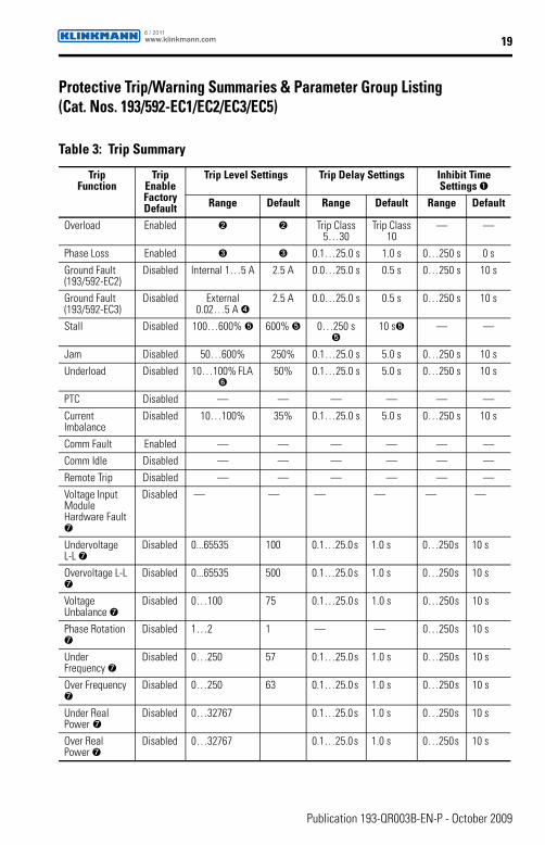
Protective Trip/Warning Summaries & Parameter Group Listing(Cat. Nos. 193/592-EC1/EC2/EC3/EC5)
Table 3: Trip Summary
TripFunction
Trip Enable FactoryDefault
Trip Level Settings Trip Delay Settings Inhibit Time Settings ➊
Range Default Range Default Range Default
Overload Enabled ➋ ➋ Trip Class5…30
Trip Class10
— —
Phase Loss Enabled ➌ ➌ 0.1…25.0 s 1.0 s 0…250 s 0 s
Ground Fault (193/592-EC2)
Disabled Internal 1…5 A 2.5 A 0.0…25.0 s 0.5 s 0…250 s 10 s
Ground Fault (193/592-EC3)
Disabled External 0.02…5 A ➍
2.5 A 0.0…25.0 s 0.5 s 0…250 s 10 s
Stall Disabled 100…600% ➎ 600% ➎ 0…250 s➎
10 s➎ — —
Jam Disabled 50…600% 250% 0.1…25.0 s 5.0 s 0…250 s 10 s
Underload Disabled 10…100% FLA ➏
50% 0.1…25.0 s 5.0 s 0…250 s 10 s
PTC Disabled — — — — — —
Current Imbalance
Disabled 10…100% 35% 0.1…25.0 s 5.0 s 0…250 s 10 s
Comm Fault Enabled — — — — — —
Comm Idle Disabled — — — — — —
Remote Trip Disabled — — — — — —
Voltage Input Module Hardware Fault ➐
Disabled — — — — — —
Undervoltage L-L ➐
Disabled 0...65535 100 0.1…25.0 s 1.0 s 0…250 s 10 s
Overvoltage L-L ➐
Disabled 0...65535 500 0.1…25.0 s 1.0 s 0…250 s 10 s
Voltage Unbalance ➐
Disabled 0…100 75 0.1…25.0 s 1.0 s 0…250 s 10 s
Phase Rotation ➐
Disabled 1…2 1 — — 0…250 s 10 s
Under Frequency ➐
Disabled 0…250 57 0.1…25.0 s 1.0 s 0…250 s 10 s
Over Frequency ➐
Disabled 0…250 63 0.1…25.0 s 1.0 s 0…250 s 10 s
Under Real Power ➐
Disabled 0…32767 0.1…25.0 s 1.0 s 0…250 s 10 s
Over Real Power ➐
Disabled 0…32767 0.1…25.0 s 1.0 s 0…250 s 10 s
www.klinkmann.com6 / 2011
20
Publication 193-QR003B-EN-P - October 2009
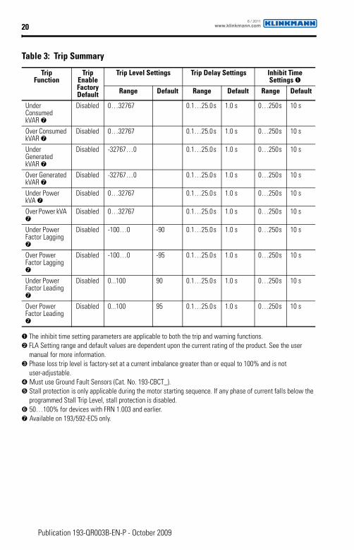
➊ The inhibit time setting parameters are applicable to both the trip and warning functions.➋ FLA Setting range and default values are dependent upon the current rating of the product. See the user
manual for more information.➌ Phase loss trip level is factory-set at a current imbalance greater than or equal to 100% and is not
user-adjustable.➍ Must use Ground Fault Sensors (Cat. No. 193-CBCT_).➎ Stall protection is only applicable during the motor starting sequence. If any phase of current falls below the
programmed Stall Trip Level, stall protection is disabled.➏ 50…100% for devices with FRN 1.003 and earlier.➐ Available on 193/592-EC5 only.
Under Consumed kVAR ➐
Disabled 0…32767 0.1…25.0 s 1.0 s 0…250 s 10 s
Over Consumed kVAR ➐
Disabled 0…32767 0.1…25.0 s 1.0 s 0…250 s 10 s
Under Generated kVAR ➐
Disabled -32767…0 0.1…25.0 s 1.0 s 0…250 s 10 s
Over Generated kVAR ➐
Disabled -32767…0 0.1…25.0 s 1.0 s 0…250 s 10 s
Under Power kVA ➐
Disabled 0…32767 0.1…25.0 s 1.0 s 0…250 s 10 s
Over Power kVA ➐
Disabled 0…32767 0.1…25.0 s 1.0 s 0…250 s 10 s
Under Power Factor Lagging ➐
Disabled -100…0 -90 0.1…25.0 s 1.0 s 0…250 s 10 s
Over Power Factor Lagging ➐
Disabled -100…0 -95 0.1…25.0 s 1.0 s 0…250 s 10 s
Under Power Factor Leading ➐
Disabled 0...100 90 0.1…25.0 s 1.0 s 0…250 s 10 s
Over Power Factor Leading ➐
Disabled 0...100 95 0.1…25.0 s 1.0 s 0…250 s 10 s
Table 3: Trip Summary
TripFunction
Trip Enable FactoryDefault
Trip Level Settings Trip Delay Settings Inhibit Time Settings ➊
Range Default Range Default Range Default
www.klinkmann.com6 / 2011
21
Publication 193-QR003B-EN-P - October 2009
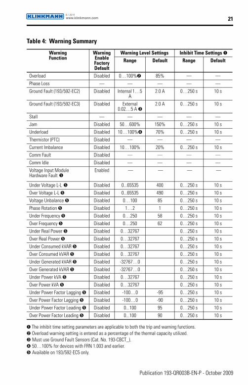
➊ The inhibit time setting parameters are applicable to both the trip and warning functions.➋ Overload warning setting is entered as a percentage of the thermal capacity utilized.➌ Must use Ground Fault Sensors (Cat. No. 193-CBCT_).➍ 50…100% for devices with FRN 1.003 and earlier.➎ Available on 193/592-EC5 only.
Table 4: Warning Summary
WarningFunction
Warning Enable Factory Default
Warning Level Settings Inhibit Time Settings ➊Range Default Range Default
Overload Disabled 0…100%➋ 85% — —
Phase Loss — — — — —
Ground Fault (193/592-EC2) Disabled Internal 1…5 A
2.0 A 0…250 s 10 s
Ground Fault (193/592-EC3) Disabled External 0.02…5 A ➌
2.0 A 0…250 s 10 s
Stall — — — — —
Jam Disabled 50…600% 150% 0…250 s 10 s
Underload Disabled 10…100%➍ 70% 0…250 s 10 s
Thermistor (PTC) Disabled — — — —
Current Imbalance Disabled 10…100% 20% 0…250 s 10 s
Comm Fault Disabled — — — —
Comm Idle Disabled — — — —
Voltage Input Module Hardware Fault �
Enabled — — — —
Under Voltage L-L � Disabled 0...65535 400 0…250 s 10 s
Over Voltage L-L ➎ Disabled 0...65535 490 0…250 s 10 s
Voltage Unbalance ➎ Disabled 0…100 85 0…250 s 10 s
Phase Rotation ➎ Disabled 1…2 1 0…250 s 10 s
Under Frequency ➎ Disabled 0…250 58 0…250 s 10 s
Over Frequency ➎ Disabled 0…250 62 0…250 s 10 s
Under Real Power ➎ Disabled 0…32767 0…250 s 10 s
Over Real Power ➎ Disabled 0…32767 0…250 s 10 s
Under Consumed kVAR ➎ Disabled 0…32767 0…250 s 10 s
Over Consumed kVAR ➎ Disabled 0…32767 0…250 s 10 s
Under Generated kVAR ➎ Disabled -32767…0 0…250 s 10 s
Over Generated kVAR ➎ Disabled -32767…0 0…250 s 10 s
Under Power kVA ➎ Disabled 0…32767 0…250 s 10 s
Over Power kVA ➎ Disabled 0…32767 0…250 s 10 s
Under Power Factor Lagging ➎ Disabled -100…0 -95 0…250 s 10 s
Over Power Factor Lagging ➎ Disabled -100…0 -90 0…250 s 10 s
Under Power Factor Leading ➎ Disabled 0...100 95 0…250 s 10 s
Over Power Factor Leading ➎ Disabled 0...100 90 0…250 s 10 s
www.klinkmann.com6 / 2011

22
Publication 193-QR003B-EN-P - October 2009
Table 5: Parameter Group ListingMonitor Params
Overload Setup Reset/Lock Advanced Setup
DeviceNet Setup
Output Setup DeviceLogix
1 L1 Current27 Single/
Three Ph 26 Trip Reset 24 Trip Enable 55 AutoBaudEnable 65 OutA Pr FltState 79 Comm Override
2 L2 Current 28 FLA Setting 53 Program Lock 25 Warning Enable 56 NonVol Baud Rate66 OutA Pr FltValue
80 Network Override
3 L3 Current 29 Trip Class 54 Set to Defaults 27 Single/Three Ph 58 COS Mask67 OutA DN FltState 81 Net outputs
4 Average Current30 OL/PTC
ResetMode 103 Test Enable* 28 FLA Setting 59 Output Assembly68 OutA DN
FltValue82 Net Out COS
Mask
5 L1 % FLA31 OL Reset
Level 104 Clear Queue* 29 Trip Class 60 Input Assembly69 OutA DN
IdlState
6 L2 % FLA 78 CT Ratio 30 OL/PTC ResetMode 61 Assy Word0 Param70 OutA DN
IdlValue
7 L3 % FLA 31 OL Reset Level 62 Assy Word1 Param 71 OutB Pr FltState
8 Average % FLA 32 OL Warning Level 63 Assy Word2 Param 72 OutB Pr FltValue
9 % Therm Utilized 33 PL Inhibit Time 64 Assy Word3 Param73 OutB DN
FltState
10 GF Current 34 PL Trip Delay74 OutB DN
FltValue
11 Current Imbal 35 GF Inhibit Time75 OutB DN
IdlState
12 OL Time To Trip 36 GF Trip Delay76 OutB DN
IdlValue
13 OL Time To Reset 37 GF Trip Level
14 Trip Status 38 GF Warn Level
15 Warning Status 39 Stall Enbld Time
16 Trip Log 0 40 Stall Trip Level
17 Trip Log 1 41 Jam Inhibit Time
18 Trip Log 2 42 Jam Trip Delay
19 Trip Log 3 43 Jam Trip Level
20 Trip Log 4 44 Jam Warn Level
21 Device Status 45 UL Inhibit Time
22 Firmware 46 UL Trip Delay
23 Dev Config 47 UL Trip Level
90 Warn Log 0➊ 48 UL Warn Level
91 Warn Log 1➊ 49 CI Inhibit Time
92 Warn Log 2➊ 50 CI Trip Delay
93 Warn Log 3➊ 51 CI Trip Level
94 Warn Log 4➊ 52 CI Warn Level
95 Elapsed Time➊ 78 CT Ratio
96 Starts Counter➊ 83 IN 1 Assignment
97 Starts Available➊ 84 IN 2 Assignment
98 Time To Start➊ 85 IN 3 Assignment
86 IN 4 Assignment
87 2-Spd Net Enable
88 2-Speed FLA Set
89 GF Trip Inhibit
99 Starts/Hour➊
100 Starts Interval➊
101 PM - # Starts➊
102 PM - Oper. Hours➊
105 GF Warn Delay➊
106 GF Sensing Range➊
➊ Series C (FRN 4.00 and higher)
www.klinkmann.com6 / 2011
23
Publication 193-QR003B-EN-P - October 2009
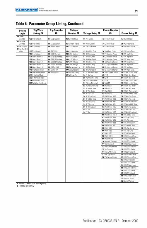
Table 6: Parameter Group Listing, Continued
DeviceLogix
TripWarn History ➋
Trip Snapshot ➋
Voltage Monitor ➌ Voltage Setup ➌
Power Monitor ➌ Power Setup ➌
79 Comm Override 132 Trip History 0 144 SS L1 Current 160 V Trip Status 156 Volt Mode 173 L1 Real Power 157 Power Scale
80 Network Override 133 Trip History 1 145 SS L2 Current 161 V Warn Status 158 V Trip Enable 174 L2 Real Power 225 PW Trip Enable
81 Net outputs 134 Trip History 2 146 SS L3 Current 162 L1-L2 Voltage 159 V Warn Enable 175 L3 Real Power 226 PW Warn Enable 82 Net Out COS
Mask 135 Trip History 3 147 SS %TCU 163 L2-L3 Voltage 215 UV Inhibit Time 176 Total Real Power 241 UW Inhibit Time136 Trip History 4 148 SS GF Current 164 L3-L1 Voltage 216 UV Trip Delay 177 L1 Reactive Power 242 UW Trip Delay
137 Warn History 0 149 SS L1-L2 Voltage 165 Ave Voltage L-L 217 UV Trip Level 178 L2 Reactive Power 243 UW Trip Level138 Warn History 1 150 SS L2-L3 Voltage 166 L1-N Voltage 218 UV Warn Level 179 L3 Reactive Power 244 UW Warn Level139 Warn History 2 151 SS L3-L1 Voltage 167 L2-N Voltage 219 OV Inhibit Time 180 Tot Reactive Power 245 OW Inhibit Time140 Warn History 3 152 SS Tot Real Pwr 168 L3-N Voltage 220 OV Trip Delay 181 L1 Apparent Power 246 OW Trip Delay141 Warn History 4 153 SS Tot kVAR 169 Ave Voltage L-N 221 OV Triip Level 182 L2 Apparent Power 247 OW Trip Level142 TripHistory Mask 154 SS Tot kVA 170 Volt Unbalance 222 OV Warn Level 183 L3 Apparent Power 248 OW Warn Level143 WarnHistory Mask 155 SS Total PF 171 Volt Frequency 223 Ph Rot Inhib Time 184 Tot Apparent Power 249 UVARC Inhibit Time299 V TripHist Mask 172 V Phase Rot 224 Ph Rot Trip 185 L1 PF 250 UVARC Trip Delay300 V WarnHist Mask 229 V UnhalInhib Time 186 L2 PF 251 UVARC Trip Level301 PW TripHist Mask 230 V UnbalTripDelay 187 L3 PF 252 UVARC Warn Level302 PW WarnHist Mask 231 V UnbalTrip Level 188 Total PF 253 OVARC Inhibit Time
232 V UnbalWarnLevel 189 kWh 10E6 254 OVARC Trip Delay233 UF Inhibit Time 190 kWh 10E3 255 OVARC Trip Level234 UF Trip Delay 191 kWh 10E0 256 OVARC Warn Level235 UF Trip Level 192 kWh 10E-3 257 UVARG Inhibit Time236 UF Warn Level 193 kVARh Con 10E6 258 UVARG Trip Delay237 OF Inhibit Time 194 kVARh Con 10E3 259 UVARG Trip Level238 OF Trip Delay 195 kVARh Con 10E0 260 UVARG Warn Level239 OF Trip Level 196 kVARh Con 10E-3 261 OVARG Inhibit Time240 OF Warn Level 197 kVARh Gen 10E6 262 OVARG Trip Delay289 PT Pri 198 kVARh Gen 10E3 263 OVARG Trip Level290 PT Sec 199 kVARh Gen 10E0 264 OVARG Warn Level
200 kVARh Gen 10E-3 265 UVA Inhibit Time201 kVARh Net 10E6 266 UVA Trip Delay202 kVARh Net 10E3 267 UVA Trip Level203 kVARh Net 10E0 268 UVA Warn Level204 kVARh Net 10E-3 269 OVA Inhibit Time205 kVAh 10E6 270 OVA Trip Delay206 kVAh 10E3 271 OVA Trip Level207 kVAh 10E0 272 OVA Warn Level208 kVAh 10E-3 273 UPFLG Inhibit Time209 kW Demand 274 UPFLG Trip Delay210 Max kW Demand 275 UPFLG Trip Level211 VAR Demand 276 UPFLG Warn Level212 Max VAR Demand 277 OPFLG Inhibit Time213 VA Demand 278 OPFLG Trip Delay214 Max VA Demand 279 OPFLG Trip Level227 PW Trip Status 280 OPFLG Warn Level228 PW Warnn Status 281 UPFLD Inhibit Time
282 UPFLD Trip Delay283 UPFLD Trip Level284 UPFLD Warn Level285 OPFLD Inhibit Time286 OPFLD Trip Delay287 OPFLD Trip Level288 OPFLD Warn Level291 Demand Period292 Num of Periods
� Series C (FRN 5.00 and Higher)➌ 193/592-EC5 Only
www.klinkmann.com6 / 2011
24
Publication 193-QR003B-EN-P - October 2009
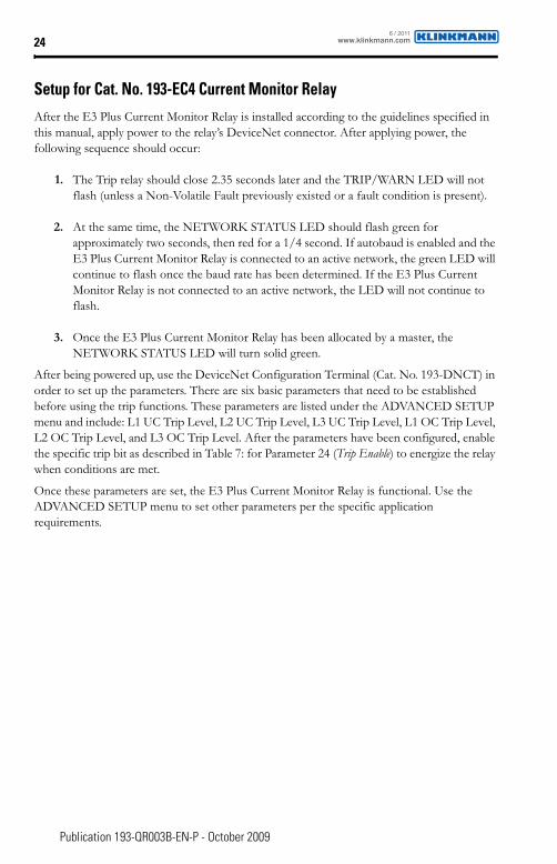
Setup for Cat. No. 193-EC4 Current Monitor RelayAfter the E3 Plus Current Monitor Relay is installed according to the guidelines specified in this manual, apply power to the relay’s DeviceNet connector. After applying power, the following sequence should occur:
1. The Trip relay should close 2.35 seconds later and the TRIP/WARN LED will not flash (unless a Non-Volatile Fault previously existed or a fault condition is present).
2. At the same time, the NETWORK STATUS LED should flash green for approximately two seconds, then red for a 1/4 second. If autobaud is enabled and the E3 Plus Current Monitor Relay is connected to an active network, the green LED will continue to flash once the baud rate has been determined. If the E3 Plus Current Monitor Relay is not connected to an active network, the LED will not continue to flash.
3. Once the E3 Plus Current Monitor Relay has been allocated by a master, the NETWORK STATUS LED will turn solid green.
After being powered up, use the DeviceNet Configuration Terminal (Cat. No. 193-DNCT) in order to set up the parameters. There are six basic parameters that need to be established before using the trip functions. These parameters are listed under the ADVANCED SETUP menu and include: L1 UC Trip Level, L2 UC Trip Level, L3 UC Trip Level, L1 OC Trip Level, L2 OC Trip Level, and L3 OC Trip Level. After the parameters have been configured, enable the specific trip bit as described in Table 7: for Parameter 24 (Trip Enable) to energize the relay when conditions are met.
Once these parameters are set, the E3 Plus Current Monitor Relay is functional. Use the ADVANCED SETUP menu to set other parameters per the specific application requirements.
www.klinkmann.com6 / 2011
25
Publication 193-QR003B-EN-P - October 2009
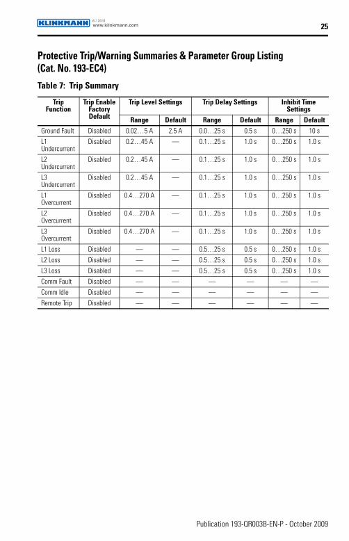
Protective Trip/Warning Summaries & Parameter Group Listing(Cat. No. 193-EC4)
Table 7: Trip Summary
TripFunction
Trip EnableFactoryDefault
Trip Level Settings Trip Delay Settings Inhibit Time Settings
Range Default Range Default Range DefaultGround Fault Disabled 0.02…5 A 2.5 A 0.0…25 s 0.5 s 0…250 s 10 s
L1 Undercurrent
Disabled 0.2…45 A — 0.1…25 s 1.0 s 0…250 s 1.0 s
L2 Undercurrent
Disabled 0.2…45 A — 0.1…25 s 1.0 s 0…250 s 1.0 s
L3 Undercurrent
Disabled 0.2…45 A — 0.1…25 s 1.0 s 0…250 s 1.0 s
L1 Overcurrent
Disabled 0.4…270 A — 0.1…25 s 1.0 s 0…250 s 1.0 s
L2 Overcurrent
Disabled 0.4…270 A — 0.1…25 s 1.0 s 0…250 s 1.0 s
L3 Overcurrent
Disabled 0.4…270 A — 0.1…25 s 1.0 s 0…250 s 1.0 s
L1 Loss Disabled — — 0.5…25 s 0.5 s 0…250 s 1.0 s
L2 Loss Disabled — — 0.5…25 s 0.5 s 0…250 s 1.0 s
L3 Loss Disabled — — 0.5…25 s 0.5 s 0…250 s 1.0 s
Comm Fault Disabled — — — — — —
Comm Idle Disabled — — — — — —
Remote Trip Disabled — — — — — —
www.klinkmann.com6 / 2011
26
Publication 193-QR003B-EN-P - October 2009
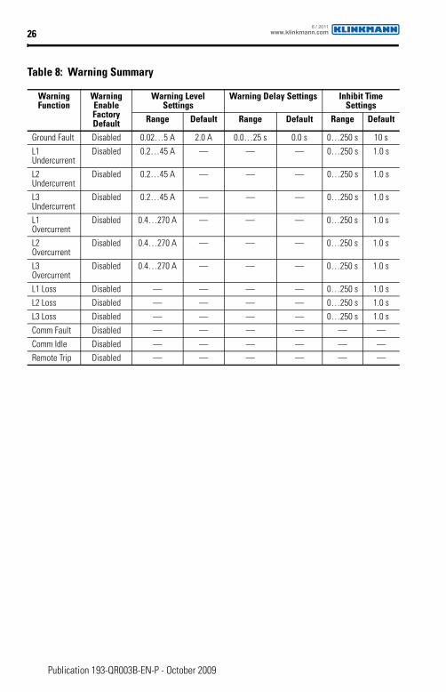
Table 8: Warning Summary
WarningFunction
Warning EnableFactoryDefault
Warning Level Settings
Warning Delay Settings Inhibit Time Settings
Range Default Range Default Range Default
Ground Fault Disabled 0.02…5 A 2.0 A 0.0…25 s 0.0 s 0…250 s 10 s
L1 Undercurrent
Disabled 0.2…45 A — — — 0…250 s 1.0 s
L2 Undercurrent
Disabled 0.2…45 A — — — 0…250 s 1.0 s
L3 Undercurrent
Disabled 0.2…45 A — — — 0…250 s 1.0 s
L1 Overcurrent
Disabled 0.4…270 A — — — 0…250 s 1.0 s
L2 Overcurrent
Disabled 0.4…270 A — — — 0…250 s 1.0 s
L3 Overcurrent
Disabled 0.4…270 A — — — 0…250 s 1.0 s
L1 Loss Disabled — — — — 0…250 s 1.0 s
L2 Loss Disabled — — — — 0…250 s 1.0 s
L3 Loss Disabled — — — — 0…250 s 1.0 s
Comm Fault Disabled — — — — — —
Comm Idle Disabled — — — — — —
Remote Trip Disabled — — — — — —
www.klinkmann.com6 / 2011

27
Publication 193-QR003B-EN-P - October 2009
Table 9: Parameter Group Listing (Cat. No. 193-EC4)
Monitor Params
Reset / Lock Advanced Setupt DeviceNet Setup Output Setup DeviceLogix
1 L1 Current 26 Trip Reset 24 Trip Enable 55 AutoBaudEnable 65 OutA Pr FltState 79 Comm Override
2 L2 Current 53 Program Lock 25 Warning Enable 56 NonVol Baud Rate 66 OutA Pr FltValue 80 Network Override
3 L3 Current 54 Set to Defaults 35 GF Inhibit Time 58 COS Mask 67 OutA DN FltState 81 Net Outputs
10 GF Current 103 Test Enable 36 GF Trip Delay 59 Output Assembly 68 OutA DN FltValue 82 Net Out COS Mask
14 Trip Status 104 Clear Queue 37 GF Trip Level 60 Input Assembly 69 OutA DN IdlState
15 Warning Status 38 GF Warn Level 61 Assy Word0 Param 70 OutA DN IdlValue
16 Trip Log 0 83 IN 1 Assignment 62 Assy Word1 Param 71 OutB Pr FltState
17 Trip Log 1 84 IN 2 Assignment 63 Assy Word2 Param 72 OutB Pr FltValue
18 Trip Log 2 85 IN 3 Assignment 64 Assy Word3 Param 73 OutB DN FltState
19 Trip Log 3 86 IN 4 Assignment 74 OutB DN FltValue
20 Trip Log 4 89 GF Trip Inhibit 75 OutB DN IdlState
21 Device Status 101 # of Starts 76 OutB DN IdlValue
22 Firmware 102 Operating Hours
23 Dev Config 105 GF Warn Delay
90 Warn Log 0 106 GF Sensing Range
91 Warn Log 1 107 UC Inhibit Time
92 Warn Log 2 108 L1 UC Trip Level
93 Warn Log 3 109 L1 UC Trip Delay
94 Warn Log 4 110 L1 UC Warn Level
95 Elapsed Time 111 L2 UC Trip Level
96 Starts Counter 112 L2 UC Trip Delay
113 L2 UC Warn Level
114 L3 UC Trip Level
115 L3 UC Trip Delay
116 L3 UC Warn Level
117 OC Inhibit Time
118 L1 OC Trip Level
119 L1 OC Trip Delay
120 L1 OC Warn Level
121 L2 OC Trip Level
122 L2 OC Trip Delay
123 L2 OC Warn Level
124 L3 OC Trip Level
125 L3 OC Trip Delay
126 L3 OC Warn Level
127 LL Inhibit Time
128 L1 Loss Trip Delay
129 L2 Loss Trip Delay
130 L3 Loss Trip Delay
www.klinkmann.com6 / 2011

28
Publication 193-QR003B-EN-P - October 2009
Table 10: Parameter Group Listing (Cat. No. 193-EC4), Continued
Short-Circuit Ratings
The Bulletin 193/592 E3 Overload relay is suitable for use on circuits capable of delivering not more than the RMS symmetrical amperes listed in the followign tables:
TripWarn History ➊ Trip Snapshot ➊132 Trip History 0 144 SS L1 Current
133 Trip History 1 145 SS L2 Current
134 Trip History 2 146 SS L3 Current
135 Trip History 3 148 SS GF Current
136 Trip History 4
137 Warn History 0
138 Warn History 1
139 Warn History 2
140 Warn History 3
141 Warn History 4
142 TripHistory Mask
143 WarnHistory Mask
➊ Series C (FRN 5.00 and Higher)
ATTENTION
!To prevent electrical shock, disconnect from power source before installing or servicing
ATTENTION
!Select the motor branch circuit protection that complies with the National Electrical Code and any othergoverning regional and local codes
www.klinkmann.com6 / 2011
29
Publication 193-QR003B-EN-P - October 2009
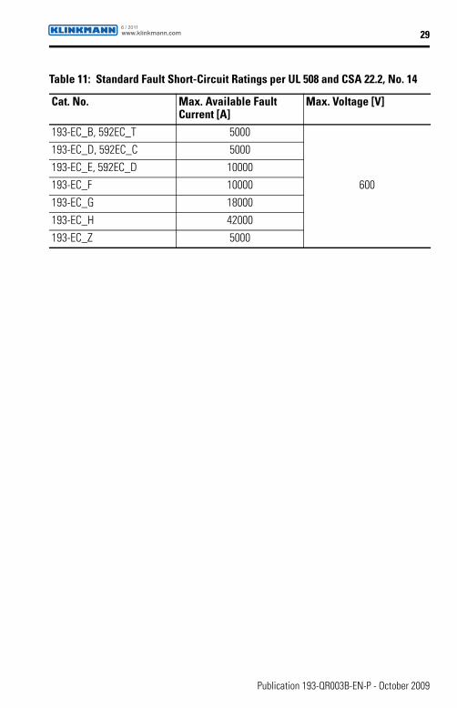
Table 11: Standard Fault Short-Circuit Ratings per UL 508 and CSA 22.2, No. 14
Cat. No. Max. Available Fault Current [A]
Max. Voltage [V]
193-EC_B, 592EC_T 5000
600
193-EC_D, 592EC_C 5000
193-EC_E, 592EC_D 10000193-EC_F 10000
193-EC_G 18000
193-EC_H 42000193-EC_Z 5000
www.klinkmann.com6 / 2011
30
Publication 193-QR003B-EN-P - October 2009
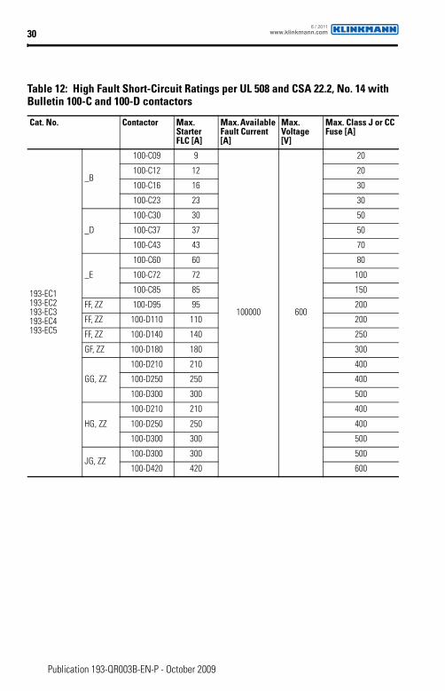
Table 12: High Fault Short-Circuit Ratings per UL 508 and CSA 22.2, No. 14 with Bulletin 100-C and 100-D contactors
Cat. No. Contactor Max. Starter FLC [A]
Max. Available Fault Current [A]
Max. Voltage [V]
Max. Class J or CC Fuse [A]
193-EC1193-EC2193-EC3193-EC4193-EC5
_B
100-C09 9
100000 600
20
100-C12 12 20
100-C16 16 30
100-C23 23 30
_D
100-C30 30 50
100-C37 37 50
100-C43 43 70
_E
100-C60 60 80
100-C72 72 100
100-C85 85 150
FF, ZZ 100-D95 95 200
FF, ZZ 100-D110 110 200
FF, ZZ 100-D140 140 250
GF, ZZ 100-D180 180 300
GG, ZZ
100-D210 210 400
100-D250 250 400
100-D300 300 500
HG, ZZ
100-D210 210 400
100-D250 250 400
100-D300 300 500
JG, ZZ100-D300 300 500
100-D420 420 600
www.klinkmann.com6 / 2011

31
Publication 193-QR003B-EN-P - October 2009
Table 13: High Fault Short-Circuit Ratings per UL 508 and CSA 22.2, No. 14 with NEMA contactors
Cat. No. Contactor Size
Max. Available Fault Current [A]
Max. Voltage [V]
Max. UL Fuse [A] Circuit Breaker/Limiter
R J
592-EC1592-EC2592-EC3592-EC5
_T 00 100000 600 — 20 —
_C
0 100000
240 30 30 FDB 3025/LFB3070R
480 30 30 FDB 3025/LFB3070R
600 30 30 —
_C 1 100000
240 60 100 FDB 3050/LFB3035R
480 30 50 FDB 3050/LFB3035R
600 30 50 —
_C 2 100000
240 100 200 FDB 3100/LFB3150R
480 60 100 —
600 60 100 —
_D 3 100000
240 200 350 FDB 3150/LFB3150R
480 100 200 FDB 3125/LFB3150R
600 100 200 FDB 3100/LFB3150R
Table 14: IFC Short-Circuit Ratings per EN60947-4-1
Cat. No. Prospective Short-Circuit Current Ir [A]
Conditional Short-Circuit Current Iq [A]
Max. Voltage [V]
193-EC_B, 592EC_T 1000
100000 690
193-EC_D, 592EC_C 3000
193-EC_E, 592EC_D 5000193-EC_F 10000
193-EC_G 18000193-EC_H 30000
193-EC_Z 1000
www.klinkmann.com6 / 2011
32
Publication 193-QR003B-EN-P - October 2009
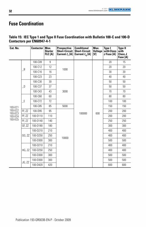
Fuse Coordination
Table 15: IEC Type 1 and Type II Fuse Coordination with Bulletin 100-C and 100-D Contactors per EN60947-4-1
Cat. No. Contactor Max. Starter FLC [A]
Prospective Short-Circuit Current Ir [A]
Conditional Short-Circuit Current Iq [A]
Max. Voltage [V]
Type I with Class J Fuse [A]
Type II with Class J Fuse [A]
193-EC1193-EC2193-EC3193-EC4193-EC5
_B
100-C09 9
1000
100000 600
20 15
100-C12 12 20 20
100-C16 16 30 30
100-C23 23 40 40
_D
100-C30 30
3000
50 50
100-C37 37 50 50
100-C43 43 70 70
_E
100-C60 60 80 80
100-C72 72 100 100
100-C85 85 5000 150 150
FF, ZZ 100-D95 95
10000
200 200
FF, ZZ 100-D110 110 200 200
FF, ZZ 100-D140 140 250 250
GF, ZZ 100-D180 180 300 300
GG, ZZ
100-D210 210 400 400
100-D250 250 400 400
100-D300 300 500 500
HG, ZZ
100-D210 210 400 400
100-D250 250 400 400
100-D300 300 500 500
JG, ZZ100-D300 300 500 500
100-D420 420 600 600
www.klinkmann.com6 / 2011
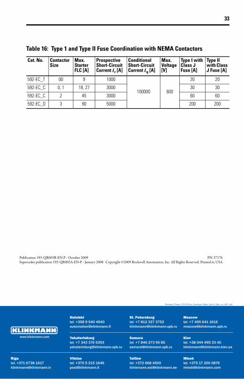
33
Table 16: Type 1 and Type II Fuse Coordination with NEMA Contactors
Cat. No. Contactor Size
Max. Starter FLC [A]
Prospective Short-Circuit Current Ir [A]
Conditional Short-Circuit Current Iq [A]
Max. Voltage [V]
Type I with Class J Fuse [A]
Type II with Class J Fuse [A]
592-EC_T 00 9 1000
100000 600
20 20
592-EC_C 0, 1 18, 27 3000 30 30
592-EC_C 2 45 3000 60 60
592-EC_D 3 90 5000 200 200
Publication 193-QR003B-EN-P - October 2009 PN-37176Supercedes publication 193-QR003A-EN-P - January 2008 Copyright ©2009 Rockwell Automation, Inc. All Rights Reserved. Printed in USA
Rockwell_Power_E3-E3-Plus_Overload_Relay_Quick_Start_en_0611.pdf
Samaratel. +7 846 273 95 [email protected]
Yekaterinburgtel. +7 343 376 [email protected]
St. Petersburgtel. +7 812 327 [email protected]
Moscowtel. +7 495 641 [email protected]
Helsinkitel. +358 9 540 [email protected]
Vilniustel. +370 5 215 [email protected]
Rigatel. +371 6738 [email protected]
Мinsktel. +375 17 200 [email protected]
Tallinntel. +372 668 [email protected]
Кievtel. +38 044 495 33 [email protected]
www.klinkmann.com