e51design consideration for deep underground protective ... · technical report no. 8 e51design...
TRANSCRIPT
TECHNICAL REPORT NO. 8
E51DESIGN CONSIDERATION FOR
* DEEP UNDERGROUND
PROTECTIVE FACILITIES
by
CARL F. BAGGE
MARCH 1972
HIM ~ I'H
OMAHA DISTRICT, CORPS OF ENGINEERS JU
OMAHA, NEBRASKA 68102
B
THIS RESEARCH WAS FUNDED BY OFFICE, CHIEF
OF ENGINEERS DEPARTMENT OF THE ARMY
PREPARED UNDER CONTRACT DACA 45-70.-C-0100BY AGBABIAN-JACOBSEN ASSOCIATES
LOS ANGELFS, CALIFORNIA
Approved for public release; distribution ',nlirnited
NATIONAL TECHNICAL
INFORMATION SERVICE" Cc" .... @ ...'" III
Security Classification
DOCUMENT CONTROL DATA. R & D(Sec ilty classilfication of title. b-dy of abstract and indexing annotation must be entered when the overall report Is classli*e,
"I ORIGINATING ACTIVITY (Corporate author) |28. REPORT SFCURITY CLASSIFICATION
Omaha District, Corps of Engineers U TIED*mha, Nebraska 68102
* 3. REPORT TITLE
Stat-,c and Dynamic Analysis of Rock Bolt Support
4. DESCRIPTIVE NOTES (Type of report and incluaive dates)
Ie~rimS. AU THt R(S) (First name, middle Initial, last name)
Carl F. Bagge
6. REPý., T O4 - 7a. TOTAL NO. OF PAGES 17b. NO. OF REFS
March 1972 1011 188a. CONTRACT OR GRANT NO. 2a. ORIGINATOR'S REPORT NUM`8ER(S)
DACA 45-70-C-0100b. PROJECT NO. Tecbnical Re;ort No. 8
141•M78012AOKIC. 9b. OTHER REPORT tIO(S) (Any other numbers that may be aesigned
TASK: 09 this -Oport)
d. WORK UNIT: 00510. OISTRIOUTION STATEMENT
Approved for public release; di~tribution unlimited.
It. SUPPLEMENTARY NOTES T12. SPONSORING MILITARY ACTIVITY
I Department of the ArmySOffice of the Chief of Engineers__Washington, D. C. 20314
13. ABSTRACT
Analytical investigations of two problems of hardening a deep undergroundprotective facility--(1) the mechanical failure of a cuvity under dynamic groundshock loading E,.nd (2) the material failure of a cavity penetration under over-burden loading and repeated ground shock loading--are reported.
Design requirements are derived for liner, backpacked liner, and roe-z boltreinforcenent, vhich function to prevent mechanical failure of cyl!ndricalcavities sited in well-fro.ctured rock and a step-by-step procedure for desiE,4is given. The results indicate that cavity survival is linearly deendentupon (1) the increment of the free-field ground shock acceleration )ccurringover a period of tvo cavity engullfnit times and (2) the magnitude Df thecavity radius. This deperence is not inconsistent with Pile Drivet testresults. The design procedure in raccaendcd as an interim until such timeas validation can be provide by laboratory and field testing or by morerigorous analytical study.
The critical nature of material failure at a cavity penetration is examinedby calculation of the inelastic response of a steel-lined penetration at thehorizontal axis of en unlined, horizontal, circulAr cylindrical cavity located at adepth of 4300 ft in a competent achiotose gneise subjected to a 25-HT 3urface burst.The resultina three-d5imensional problem is eynined by treating a tvo-dimensional
FORM , 14'0"•., .. G, •73 "ULACZS 00 "O.. 1.0*, 1 JAN 04. WHICH It Oitj 7 LtasOifY uoC I" 7 OLUTO POR AR1.Y U49.
Security Classification
proble--a transverse slice of the penetrati-on at the cavity wall.The response of the awavi'y awq from the penetration is assumedto be elastic. The mnanusis is accomplished with a finite elementcode that allows for overburden loading, emp•aceseat of the liner,and repeated ground shock loading, in sequence. Ground shockloading is applied statically. Material strength is assmed tobe unaffected by repeated loading. The analysis indicates tbt~t(1) steel-lined penetrations can be adequately and cost-effectivelydesigned to withstand repeated attack with large-yield weapons p-o-vided that there is no significant deterioration of rock strengthwith each attack and (2) the analysis technique used here, or anequivalent technique, can be used effectively by tody's designer,provided material properties data are available. R'Accwaendationsare given for further study of the penetration problem.
14 LINK A LINK a LINK C
ROLE WT ROLE WT ROLE WT
Backpacked LinerCavity FailureCavity PenetrationDynmic LoadingLiner AccelerationMaterial FailureMechanical FailureProtective FacilitiesRepeated LoadingRock BoltingRock MechanicsTunnel Liners
UNCLASSIFIED
Security Cleanlflcation
t
TECHNICAL REPORT NO. 8
DESIGN CONSIDERATIONS FOR DF ,0UNDERGROUND PROTECTIVE FACILIT.. 7
by
CARL F. BAGGE
MARCH 1972
OMAHA DISTRICT, CORPS OF ENGINEERSOMAHA, NEBRASKA 68102
THIS RESEARCH WAS FUNDED BY OFFICE, CHIEF OF ENGINEERSDEPARTMENT OP THE ARMY
PREPARED UNDER CONTRACT DACA 45-70-C-0100BY AGBABIAN-JACOBSEN ASSOCIATES
LOS ANGELES, CALIFORNIA
Approved for Public Release; Distribution Unlimited
J.- Q
ABSTRACT
Analytical investigations of two problems of hardening a deepunderground protective facility--(1) the mechanical, failure of a cavityunder dynamic ground shock loading and (2) the material failure of acavity penetration under overburden loading and repeated ground shockloading--are reported.
Design requirements are derived for liner, backpacked liner,and rock bolt reinforcement, which function to prevent mechanical failureof cylindrical cavities sited in well-fractured rock and a step-by-stepprocedure for design is given. The results indicate that cavity sur-vival is linearly dependent upon (1) the increment of the free-fieldground shock acceleration occurring over a period of two cavity engulf-ment times and (2) the magnitude of the cavity radius. This dependenceis not inconsistent with Pile Driver test results. The design procedureis recommended as an interim until such time as validation can be pro-vided by laboratory and field testing or by more rigorous analyticalstudy.
The critical nature of material failure at a cavity penetra-tion is examined by calculation of the inelastic response of a steel-lined penetration at the horizontal axis of an unlined, horizontal,circular cylindrical cavity located at a depth of 4300 ft in a competentschistose gneiss subjected to a 25-MT surface burst. The resultingthree-dimensional problem is examined by treating a two-dimensionalproblem--a transverse slice of the penetration at the cavity wall. The-response of the cavity away from the penetration is assumed to be elastic.The analysis is accomplished with a finite element code that allows foroverburden loading, emplacement of the liner, and repeated grouhd shockloading, in sequence. Ground shock loading is applied statically.Material strength is assumed to be unaffected by repeated loading. Theanalysis indicates that (1) steel-lined penetrations can be adequatelyand cost-effectively designed to withstand repeated attack with large-yield weapons provided that there is no significant deterioration ofrock strength with each attack and (2) the analysis technique used here,or an equivalent Ichnique, can be used effectively by today's designer,provided material properties data are available. Recommendations aregiven for further study of the penetration problem.
PREFACE
This investigation vae authorised by the Chief of Engineers (ENGJC-DI)
and was performed in FY 1971 under Contract No. DACA 45-T0-C-0100, between
the Omaha District, Corps of Engineers and Agbabian-Jacobsen Associates,
Los Angeles, California. This work is a part of a continuing effort to
develop methods which can be used to design underground openings in
jointed rock to survive the effects of nuclear weapons.
This report was prepared under the supervision of Mr. R. W. Anderson,
Project Manager. Mr. Carl F, Bone served as the Principal Investigator
for Agbabian-Jacobsen Associates.
During the work period covered by this report, Colonel B. P. Pendergrass
vas District &ngineer: Charles L. Hipp and R. G. Burnett were Chief,
Engineering Division; C. J. Distefano was Technical Monitor for the Omaha
District under the general supervision of Ke ndall C. Fox, Chief, Protective
Structures Branch. Dr. J. D. Smart mnd D. G. Heituann participated in the
monitoring work.
iii
CONTENTS
Section
1 INTRODUCTION ........ ................... .l... 1
1.1 Study Objectives ......... ........ ..... . 11.2 Background ....... ................. .I... 11.3 Report Organization ........ ............. 6
2 MECHANICAL FAILURE OF A CAVITY UNDER DYNAMICLOADING ................ ..................... 7
"2.1 Introduction .... ................ 72.2 Necessary Conditions for Loss of Structural
Integrity ........ ...................... 82.3 Restraining Stresses Necessary to Prevent
Loss of Structural Integrity .... ........ 92.4 Required Resistance of Cavity Reinforcement . 132.5 Design Procedure ..... .............. ... 222.6 Discussion ....... ................. .... 24
3 MATERIAL FAILURE OF CAVITY PENETRATIONS ..... .. 38
3.2 Problem Definition and Method of Solution . . 393.3 Results ........ ................... .... 413.4 Physical Interpretation of Results ..... .. 413.5 Implication of Results in Design ........ ... 42
4 CONCLUSIONS AND RECOMMENDATIONS ..... ......... 59
4.1 Mechanical Failure of a Cavity Under DynamicLoading ........ ................... .... 59
4.2 Material Failure of Cavity Penetrations . . . 59
REFERENCES .......... .................... .... 61
Appendix
A MATERIAL PROPERTY PARAMETERS FOR PENETRATIONCALCULATION ......... ................... .... 62
B GROWTH OF INELASTIC RESPONSE IN THE VICINITY OF ACAVITY PENETRATION THROUGH FIRST GROUND SHOCKAPPLICATION ......... ................... .... 68
C INSTEP CODE ........... ................... ... 83
iv
CONTENTS (CONTINUED)
ILLUSTRATIONS
Figure
2-1 Mechanical Failure of Cavity ......... • ....... 26
2-2 Three Patterns of Planes of Weaknes. ........... 27
2-3 Transient Response of Circular Cylindrical Cavityto Piecewise Linear Pulse .... ............ ... 28
2-4 Stresses at Points on Circle .............. .... 30
2-5 Transient Acceleration Response on Shadow Side ofUnlined Cavity ........ .................. ... 31
2-6 Plot of Time Function Q(t) (Equation 2-6) . .. 35
2-7 Liner Reinforcement ........... ............... 36
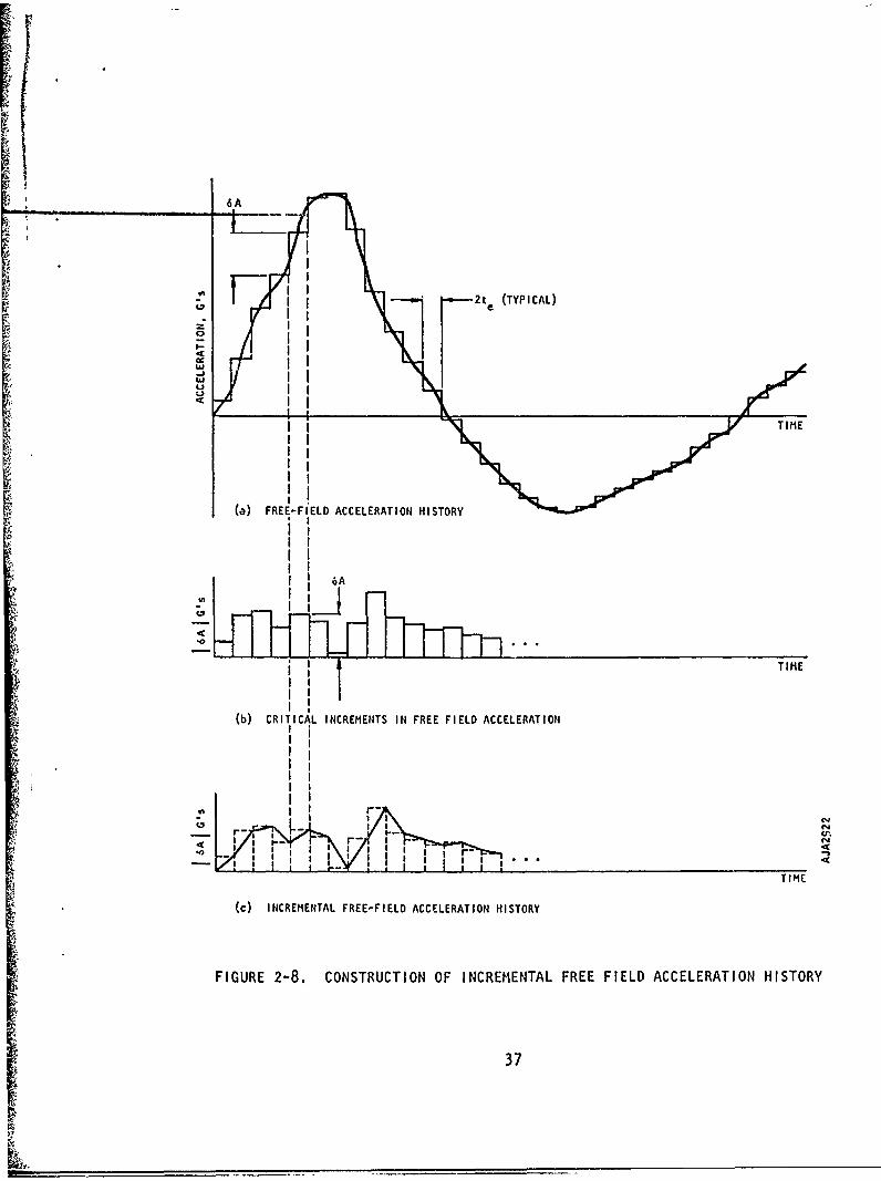
2-8 Construction of Incremental Free-FieldAcceleration History ..... ............... .... 37
3-1 Idealization of Penetration Problem ...... .. 44
3-2 Elastostatic Stress Concentration Factors forPenetration of Horizontal Cylindrical Cavity . . . 45
3-3 Cavity and Penetration Maximum Stresses ...... 46
3-4 Ground Shock and Overburden Stresses Versus Depth 47
3-5 Penetration Problem Configuration ............ 48
3-6 Finite Element Mesh of Penetration .......... ... 49
3-7 Yield Criterion for Rock Material .. ........ ... 50
3-8 Radial Displacement of Penetration Crown ..... 51
3-9 Radial Displacement of Penetration Springline . 52
3-10 Residual Radial Displacemencs of Penetration Liner 53
3-11 Peak Transient Radial Displacements of PenetrationLiner ............. ...................... ... 54
3-12 Growth of Inelastic Response in Vicinity of thePenetration ........... ................... ... 55
v
LIST OF SYMBOLS
SECTION 2
A180o = Acceleration of the cavity wall at 0 = 1800
Arb = Effective cross sectional area of rock bolt
C = Effective propagation velocity of ground shock
DLFrb = Dynamic load factor for rock bolt
DLF = Dynamic load factor for integral liner in breathing mode0
DLF 2 = Dynamic load factor for integral liner in ovaling mode
DLFI = Dynamic load factor for backpacked liner in breathing mode0
DLF2 = Dynamic load factor for backpacked liner in ovaling mode= Effective Young's modulus of liner
Ebp = Effective Young's modulus of backpacklng
Erb = Effective Young's modulus of rock bolt
g = Acceleration of gravity
h = Liner thickness
h = Backpacking th:cknessbp
K = Ratio of stress components (normal to lateral) in groundshock wave
kbp = Effective radial stiffness of backpac!'ing
k° = Radial stiffness of liner in breathing mode
k2 = Effective radial stiffness of liner in ovaling mode
L = Length of rock bolt
M = Bending moment in liner
m = Effective mass of liner
mbp = Effective mass of backpacking
vi
I
LIST OF SYMBOLS (CONTINUED)
SECTION 2
N = Thrust in liner
Q(t) = (1-0.5 74-) t
R = Cavity radius
r = Radial coordinate
S = Rock bolt spading
Trb = Vibration period of rock bolt= Vibration period of integral liner in breathing mode
T2= Vibration period of integral liner in ovaling mode
T' = Vibration period of backpacked liner in breathing mode0
T2 = Vibration period of backpacked liner in ovaling mode
t = Time
te - 2R/C, engulfment time of cavity
td = 4R/C, duration time of transient interaction
V1800 = Velocity of the cavity wall at 0 = 1800
v = Particle velocity
= Angle between direction of ground shock propagation andjoint direction defined in Figure 2-2
y = Weight density of rock
Ybp = Weight density of backpacking
yx =Weight density of liner
Yrb = Weight density of rock bolt
6A = SA'/
6A = Increment in free field acceleration
vii
-• LIST OF SYMBOLS (CONTINUED)
SECTION 2
o = Angular coordinate measured from head-on azimuth of cavity
ii = Ductility ratio
v = Poisson's ratio
p - Mass density of rock
o = Stress
abp = Radial stress in backpacking
Soff = Free field ground shork stress
a M = Liner stress due to bending moment
ow = Liner stress due to thrust
NM N M
a =Radial stress in free field
ar6 = Shear stress in free field
aff = Intermittent free field stress
a Ir = Modified radial restraining stress
arI = Modified shear restraining stress
viii
LIST OF SYMBOLS (CONTINUED)
•.• SECTIO1N 3
SEB = Bulk modulus
C Propagation velocity of ground shock
CI, C2 = Constants defined in Figure 3-7
D = Depth of facility
G = Shear modulus
SE = Young's modulus of rock
f = Yield surface function
K gs = Ratio of stress components behind ground shock frcnt
Kob = Ratio of vertical to horizontal overburden stress
ill J;' J2' = Stress invariants defined in Figure 3-7
1N = Decay rate of ground shock stress defined in Figure 3-2
S = Slant range of burst
W = Weapon yield
a = Angular coordinate defined in Figure 3-2
alp a2 = Constants defined in Figure 3-7
y = Weight density of rock
£off = Free field strain
0 = Angular coordinate defined in Figure 3-2
o = Enhanced free field stress
a = Stress detined in Figure 3-2
aob = yD, vertical overburden stress
aoff = Vertical ground shock stress for direct overhead burstI: ix
SECTION 1
IMCIODUCTION
1.1 STUDY OBJECTIVES
The two objectives of this study were
a. To derive design requirements for preventing mechanicalfailure of deep underground cavities subjected to nuclearground shock
b. To study mate, i1 failure of a deep underground cavitypenetration subjected to nuclear ground shock
1.2 BACKGROUND
The past decade has seen a concerted effort to develop adesign methodology for reinforcing deep underground cavities subjectedto nuclear-weapon-induced ground shock and in situ stresses primarilythrough a field testing program consisting of the Hard Hat and PileDriver events. The principal objective of these tests was to demon-strate the viability of a cavity liner concept comprising a relativelyflexible liner surrounded by soft packing and to empirically developdesign parameters for this concept. The premise for this concept wasthat a cavity would survive much closer to a nuclear burst if the linerwas separated from the cavity wall by a soft packing material, assumingthe cavity wall bulks due to yielding and flow of the adjacent rock.Only incidental attention, in terms of numbers of cavity sectionstested, was given to other presumably less rugged concepts, e.g.,unlined, rock-bolted, integrally lined, etc., which might survive atgreater ranges.
In spite of this decade of concerted effort, further studiesare required to develop well-defined design procedures for the harden-ing of deep underground cavities against ground shock. The Hard Hatand Pile Driver events left many questions unanswered and raised still
2
others. Still unknown are the effect of cavity size on survivability,and the design parameters for siting conditions other than for thattested. Questions raised pertain to explaining cavity and penetrationfailures which were definitely not of a bulking nature, and to defin-ing survivability under multiple-attack of the cavity sections andpenetrations that were declared to have survived.
The need for and the adequacy of the backpacked liner asevolved in the Pile Driver event is questionable today (1971). Withthe present threat of virtually zero-CEP delivery of repeated weapons,it is highly questionable that the evolved structure concept or anycontents could survive repeated pounding of an intensity whichseverely bulks cavity walls with just one attack. Moreover, it isapparent now after study of the Pile Driver results that another fail-ure mode, mechanical failure, is inadequately prevented or accommodatedby the evolved concept. Finally, the need for the evolved concept isin serious doubt as evidenced by preliminary study which shows thatbulking resulting from material failure can be virtually eliminated byjudicious selection of site location, depth of siting, and cavity design.
The Hard Hat and Pile Driver events at the Nevada Test Site,in conjunction with the Hard Rock Silo Development (HRSD) test programat Cedar City, Utah, have, however, provided information on the failuremechanisms of lined and unlined cavities in rock. What has becomevividly clear after study of these tests is that two distinct types ofground-shock-induced failure of a rock cavity are possible and must beaccounted for in design:
Material failure
Mechanical failure
An appreciation of the distinction between material and mechanical fail-ure and its implications to design are, in general, lacking in thetechnical community. One notable exception, however, are the discus-sions of test results for the rock bolting experiments conducted in thePile Driver event (Reference 1).
Material failure is characterized by yielding, flow, andswelling of the rock within the interaction zone to such an extent thatthere is a permanent reduction in cavity volume.' This type of failurecan occur only when the in situ yield strength of the intact rock isexceeded and when mechanical failure is preclsdJed. Material failurewas dramatically exhibited in the highly striesetd close-in drifts of thePile Driver event (Reference 2).
2
Mechanical failure, on the other hand, is characterized byrelative movement along planes of weakness (joints, fractures, partings,separations, etc.) lying within the interaction zone.* Mechanical
failure actually commences with the development of the cavity duringexcavation, where it is manifest as a general loosening of the rock
adjacent to the cavity. During ground shock loading, the loosening
effect is increased and appears as a swelling of the cavity walls underthe best of conditions, and, as a worst case, as loss of structuralintegrity of the cavity walls. Various degrees of mechanical failurewere in evidence in the more remote drifts, tunnels, and shafts of thePile Driver event and the HRSD test program. Failures included swellingof the cavity walls without loss of structural'integrity--easily mis-taken for material failure--isolated rock block expulsions, partialcollapse of cavities, and ccmplete collapse of a cavity with the forma-tion of a new cavity in the adjacent virgin rock.
Loss of cavity-wall structural integrity can be triggered bythe expulsion of unkeyed blocks of rock into the cavity resulting from(1) the enhanced (or reduced) acceleration of the cavity, relative tothe free-field, on the head-on (or back) face during interaction withthe free-field pulse at times of rapid change in acceleration, such asduring initial engulfment, and (2) the tendency for tensile circumfer-ential straining, i.e., unkeying action, at the head-on and back faceazimuths. Depending upon the circumstances, the expulsions of rockblocks may or may not.lead to further loss of structural integrity.Evidence that this mechanism exists can be found in the Pile Driverevent and the HRSD test'program ROCKTEST'II. In the Pile Driver event,a large rock block (roughly 2 by 4 by 8 ft) was expelled from the newlyexcavated extension of the malo access shaft (Reference 2).. The esti-mated free-field stress and acceleration levels at this range were10,000 psi and 20 g, respectively. In the ROCKTFST 11 even't, a rockblock (roughly 4 by 4 by 8 ft) was expelled from the wall of a pre-viously tested cavity located in an adjacent test bed (HANDEC II) bythe ROCKTEST II generated ground shock (Reference 3). It is estimatedthat a free-field acceleration of 10 to 20 g existed at the range ofthis cavity.
These are two examples of the occurrence of the expulsiontriggering mechanism without further loss of structural integrity.Whether this mechanism was responsible for the more serious mechanicalfailures seen in the Pile Driver and ROCKTEST II events cannot beanswered. Other triggering mechanisms are, of course, possible. For
The tightness of planes of weakness at depth, the confinement at depth,and the remoteness of a deep underground facility from the craterregion preclude all block motion other than that described here, i.e.,that originating within the interaction zone.
example, the simultaneous collapse of an entire forward wall under asevere acceleration is possible. Similarly, the buckling of severelycompressed layers, which have been subjected to gravity stoping, isalso a possible mechanism. It is not of major importance at this timeto be able to identify the triggering mechanisms of mechanical failure,but rather to recognize that mechanical failure occurs, that it canoccur in backpacked and integrally-lined cavities under a severe enoughenvironment, that it is different from material failure, and 'hat itcannot be successfully treated as material failure.
The loss of structural integrity becomes significantly moreimminent with each attack because of progressive degradation of the"strength" of the planes of weakness with each attack. This fact wasdriven home by the report (Reference 2) that the unlined access tunnelsof the Hard Hat experiment ". . . were severely damaged by the PileDriver detonation and large quantities of rock fell into the openings."The Pile Driver acceleration environment, less severe than the previousHard Hat environment, is estimated to be 20 to 100 g at various pointsalong the access tunnels.
It is apparent from the above discussion that the facilit,designer must contend with three manifestations of cavity failure:
a. Swelling of the cavity walls resulting from materialfailure of the surrounding rock
b. Swelling of the cavity walls resulting from mechanicalfailure of the surrounding rock
c. Loss of structural integrity (large scale mechanicalfailure) of the cavity wall
The designer can adopt either of two design philosophies, preventionof failure or accommodation of failure. The type and severity offailure determining whether the conceptual design approach shouldemploy preventive or accommodating design philosophy (e.g., choosingbetween an unlined cavity, rock bolting, an integral liner., or abackpa-ked liner) is dependent principally upon the following factors:
a. In situ strength of intact rock material
b. Tectonic state of stress
c. Overburden stress intensity
d. Ground shock intensity
r
e. Stress distribution as determined by cavity geometryand orientation, cavity penetrations, and proximity toadjacent cavities
f. Pattern and quality of planes of weakness
Sg. Number of attacks
The designer, in conjunction with the agency sponsoring a deep under--ground protective facility, can control to a large degree the severityof material failure as influenced by factors a through f by judiciousselection of site location, depth of burial, ane cavity design. Thislatitude in controlling material failure, which i,-identally, isvirtually absent in the design of surface or near-surface protectivefacilities, is an important consideration during the conceptual designof a deep underground protective facility. Material failure may bevirtually eliminated for unconfined compressive rock strengths greaterthan 30 ksi, provided that there is no significant deterioration in
2 rock strength with each successive attack.
In earlier studies carried out at AJA, a cavity liner conceptwas investigated that consisted of a protective liner and a layer of•elatively stiff backpacking interposed between liner and cavity walls.hp function of the backpacking in this case, however, was to buttress
cavity walls against mechanical failure and, at the same time, toattenuate the more or less elastic deformation of the cavity wall to thepoint that the liner.will survive multiple attacks. In other words, theliner and backpacking are designed to act as the structural keystone ofthe presumably incompetent cavity.
In these studies, it was also shown that material failure isinevttable for cavity penetrations. Unfortunately, the penetrationexperiments conducted in the Pile Driver event, reported in Reference 4,shed little light on the material failure of penetrations for a numberof reasons. First, the tunnel sections in which the unlined penetrationswere located experienced either mechanical or material failure. In the
A case of the bank of steel-lined penetrations located closest to theworking point, severe material failure masks the response of the pene-trations. The most remote bank of lined penetrations .ias reported tohave survived; however, no measurements of cross-section distortionwere reported that would have indicated the degree of material failurefor the particular loading condition, penetration-tunnel orientation,or penetration design.
This, then, is the background from which the two tasks underconsideration--study of mechanical failurL. of cavities and study ofmaterial failure of cavity penetrations--were formulated.
5
1.3 REPORT"ORGANIZATION
Design requ;rements for prevention of mechanical failure of acavity are derived and presented in Section 2. In Section 3, the studyof material failure of a cavity penetration is presented. Conclusionsand recommendations are presented in Section 4. Appendixes A, B, and Csupply additional documentation of the material failure study reportedin Section 3.
6
SECTION 2
MECHANICAL FAILURE OF A CAVITY UNDER DYNAtIIC LOADING
2.1 INTRODUCTION
Consider the two cases shown in Figure 2-1 and imagine thatthe planes of weakness cannot sustain tensile stresses and that theblocks of rock do not support one another through wedging action. ForCase (a), the free field without the cavity, there willibe littletendency for relative movement between the cavity core and either ofthe regions containing planes of weakness. For Case (b), however, itis easy to visualize that there will be a marked tendency for relativemovement of the shadow region into the cavity during initial engulf-ment, and the illuminated region into the cavity as the free-fieldground shock velocity begins to decay from its positive peak. Thismarked tendency for relative movement of the rock into the cavitycould, if left unchecked by cavity reinforcement, lead to loss ofstructural integrity of the cavity.
The purpose of this section is to present upper bound designrequirements for reinforcement that prevents loss of structural integrityof a circular cylindrical cavity under dynamic ground shock loadingdirected perpendicular to the cavity axis. Three types of cavity rein-forcement are considered: liner, backpacked liner, and rock bolts.
The material in this section has been organized as follows.
In Section 2.2, the circumstances necessary for loss of structural inte-grity are determined. The restraining stresses which must be applied tothe cavity wall to prevent loss of structural integrity are derived inSection 2.3. The required resistance of the cavity reinforcement whichmust supply the restraining stresses are derived in Section 2.4. A.step-by-step design procedure is given in Section 2.5. Finally, adiscussion of the design requirements is presented in Section 2.6.
1 7
2.2 NECESSARY CONDITIONS FOR LOSS OF STRUCTURAL INTEGRITY
2.2.1 Nonwedging Pattern of Planes of Weakness
It is necessary to postulate that unwedged blocks of rockexist in the shadow and/or illuminated region of the cavity in order todevelop a tendency for loss of structural integrity. The reasonablenessof this postulation will become apparent upon exami-nation of the threesimple patterns of planes of weakness shown in Figure 2-2. A singleset of planes of weakness does not present a critical condition formechanical failure (Figure 2-2(a)). ror a set of nonorthogonal planes(Figure 2-2(c)), unwedged blocks of rock are presented when the direc-tion of ground shock propagation is parallel to the long diagonal of theformed blocks. Figure 2-2(b) shows that unwedged blocks of rock arepresented wherever the direction of ground shock propagation ;s parallelto a diagonal of the formed blocks. A critical condition also existsfor the orthogonal set of planes wheneve" the direction of ground shockpropagation is parallel to a set of relal:ively compressible planes ofweakness. Since multiple sets of planes of weakness are almost alwaysencountered in practice, it is real istir. to postulate that unwedgedblocks of rock exist in the shadow and illuminated regions of thecavity.
The following assumption will therefore be made regardingplanes of weakness:
The entire interaction zone of the cavity is cut byseveral sets of planes of weakness of negligible tensilestrength in such a fashion that (11 the characteristicdime, -ions of the blocks of rock are small compared tothe cavity diameter and (2) the blocks of rock are notmutually supported by wedging action.
2.2.2 Critical Incremental steps in Free-Field Acceleration
Imagine that a cavity is engulfed by a piece-wise linearground shock stress (velocity) disturbance. A typical interactionresponse is shown in Figure 2-3. Figure 2-3(c) shows that the responseis quasistatic except immediately following an incremental step in thefree-field acceleration, at which time the response is truly dynamic.Only during these brief periods of dynamic interaction will there exista tendency for relative movement of the rock into the cavity, and hence,a need for cavity reinforcement.
8
The following incremental steps in free-field accelerationare critical:
a. An incremental step in the free-field acceleration, that
produces a decrease in forward velocity will tend toforce the rock in the illuminated region to move into"the cavity.
b. An incremental step in free-field acceleration thatproduces an increase in the forward velocity will tendto force rock in the shadow zone into the cavity.
In effect, reinforcement is required for each increment in acceleration.
2.3 RESTRAINING STRESSES NECESSARY TO PREVENT LOSS OFSTRUCTURAL INTEGRITY
The stresses which would have to be applied to the cavity wall(after complete engulfment) to completely nullify the presence of thecavity are (see Figure 2-4):
" rr(t) = aff(t)[cos2 e + K sin 20
= 0.5 aff W!. 1 + K + (1 - K) cos 2e] (2-1)
"" r6(t) = 0.5 aff(t)(1 - K) sin 20
where
a rr (t) = Radial restraining stress history
a r6t) = Tangential restraining stress history
off(t) = Free field ground shock stress history
K = Ratio of stress components behind ground shockwave front
0 = Angular coordinate measured from head-on point ofcavity
9
4
However, with reference to the discussion in Section 2.2.2, it is nec-essary only to apply a short-duration restraining stress at points ofacceleration discontinuity in order to prevent loss of structural inte-grity of the cavity. These modified restraining stress a'r and a'will be assumed to have the same spatial dependence as a and
rrr
i .e., 'r r
a'rr(t) = 0.5 aff(t)[1 + K +4 (1 - K) cos aO](2-2)
a'rCt) = 0.5 o f(t)(1 - K) sin 20
where off(t) is an intermittent free-field stress history to bedefined below. It is important to realize that the application of the.stresses given by Equation 2-1 to the cavity wall will completelynullify the presence of the cavity in the free field at all times;whereas, the application of the stresses given by Equation 2-2 isrequired to only nullify the differential motions between the cavityand free field at points of discontinuity in a linearized free fieldground shock stre..s history.
An unduly conservative approach to the calculation of Offassumes that the total change in free-field stress at points of dis-continuity must be supplied for a duration of 2 te, i.e., the presenceof the cavity must be completely nullified in the sense of Equation 2-1:
af = pC SA'tOff=(2-3a)
= 4Ry 6A t-2te
where
t = Time 0 5 t 5 2t , reckoned from the time ofdiscontinuity arrival
te = 2R/C = Engulfment time of cavity
C = Effective propagation velocity of ground shock
R = Cavity radius
6A = 6A'/g increment in free-field acceleration, i.e.,change in slope of the velocity history at a pointof discontinuity
y = pg, the specific weight or wieight density
10
A reasonably conservative estimate of a'f can be obtainedby consideration of typical dynamic response at the shadow side of thecavity produced by an incremental increase in the free-field acceler-ation 6A'. This response, shown in Figure 2-5*, may be thought of asoccurring under an initial engulfment step or any step in the free-field acceleration (see Figure 2-3). Figure 2-5 compares both thetangential and radial components of acceleration of the cavity wallat various points with the corresponding components of the free-fieldacceleration. The shaded areas in Figure 2-5 are a measure of thedifferential motion which takes place between the free-field and thecavity wall. The requirement that the cavity reinforcement must supplythe restraining stresses ar and a'r in such a manner that thecavity wall is accelerated with the free field is imposed. Therefore,the acceleration histories which must be supplied by a' and a'rr rOare the shaded areas shown in Figure 2-5. The acceleration historywhich must be supplied at the extreme shadow point (see Figure 2-5(g))can be approximated by
2t - (2-4)
Integration of Equation 2-4 with respect to t gives thefollowing velocity history:
V = 2te 6A'Q(t) (2-5)
where
Q(t) t - . (2-6)
Equation 2-6 is plotted in Figure 2-6.
The differential displacement at 0 = 00, r = R can beapproximated from Figure 2-5(i) by double integration of
A00 6A' (1 - t/2te)
where t is reckoned from t = .5te. Performing the integrations gives
t2 t3SD = 6A' (t_- t )
2 l2 te
*This solution has been obtained with the GARNET Code. The code calcu-lates the closed-form solution for elastodynamic response of a lined orunlined circular cavity located in an elastic continuum (Reference 5).
11
The maximum 6D is6D = A-2max 3 e
for a cavity in unjointed rock. For an unlined cavity siLed in criticallyjointed rock, the differential motion would vary roughly as the free fielddisplacement since the rock at the cavity remains stationary (neglecting theforce of gravity), as discussed in Section 2.1. The differentialdisplacements for the other azimuths are similar.
Assuming that stress is related to velocity by
a = PCv (2-7)
the correct relationship for one-dimensional wave propagation and areasonable approximation for the case under consideration here, leadsto the following expression for the radial restraining stress at8 = 180 deg:
Cr5t) = 4 "•y 6A Q(t) (2-8)rr 11800°
where y is the weight density of the rock and 6A is the accelerationincrement expressed in g's. It can be verified that Equation 2-8 isdiso applicable at 0 = 0 deg during an incremental reduction in thefree-field acceleration.
Evaluating Equation 2-2a at 180 deg and using the result inEquation 2-8 leads to
a'f(t) = 4Ry 6A Q(t) (2-3b)
This differs from the more conservative estimate of oaf obtained inEquation 2-3a by the factor [1 - 0.5 t/(2te)].
Assuming that Equation 2-3b is a reasonable approximation forother 0 leads to the following expressions for restraining stressesupon substitution in Equation 2-2:
orr(t) = 2Ry 6A[l + K + (1 - K) cos 20]Q(t) (2-9)
Ore(t) = 2Ry 6A(l - K) sin 20 Q(t)
These stress histories must be applied to the rock by the cavity rein-forcement during each increment in the free-field acceleration. Itis, of course, equivalent to think of the stresses given by Equation 2-9as those being applied to the cavity reinforcement by the surrounding rock.
12
2.4 REQUIRED RESISTANCE OF CAVITY REINFORCEMENT
The effective dynamic resistance of a liner, a backpackedliner, or a rock-bolt cavity reinforcement which is required to resistthe stresses given by Equation 2-9 is calculated here using the dynamicanalysis procedure outlined in Chapter 9 of the ASCE Manual of Engi-neering Practice No. 42 (Reference 6). It is assumed that the readeris familier with this procedure. However, as a very brief introductionto this procedure, the following paragraph is extracted from Reference 6.
"The principal method for dynamic design describedhere is a simplified and rapid procedure for deter-mining the relationships among the following: Thepeak force applied dynamically to a structure orstructural element, the effective dynamic resistanceof the element, the effective duration of theapplied force, the period of vibration of the element,the maximum acceptable deflection of the element,and the limiting deflection in the elastic range.The procedure described, although it may involvecomputational inaccuracies of the order of 20 to 25%in sorne cases, .5! sufficiently accurate for allpractical purposes because the parameters enteringinto the problem are not accurately determinable.Even a much more precise analysis, by procedureswhich.jnvolve no analytical inaccuracy, could notordinarily reduce the overall uncertainty belowa value perhaps even greater than 25% because ofthe general physical complexity of the problem,and also because of the lack of definite'knowledgein advance concerning:
1. The blast pressure at a given distance
"from a given energy of detonation;
2. The duration of the blast wave; or
3. The structural parameters.
The method of analysis requires:
1. A description of the loading-time curveapplied to the structure.
2. A knowledge of the limiting structuralresistance.
13
3. The shape of the resistance-deflectioncurve for the structure, and especiallya characterization of it by a du.c:tilityparameter giving the permissible mvxim.mdeflection in relationship to the effec.-tive yield-point deflection of thestructure.
4. A measure of the period of vibration inthe effective "elastic range" of thestructure."
The comments regarding inaccuracies and uncertainty are most applicableto the problem here.
It will be assumed that thp stress histories given by Eqa-tion 2-9 are actually triangular in shape with the same peak stress andsame duration (td = 2te); see Figure 2-6.
2.4.1 Liner
A liner of thickness h, radius R, Young's modulus E, andweight density yk is used to reinforce the cavity (Figure 2-7).
The following assumptions are made:
a. The liner thickness is small compared to the liner
(cavity) radius (R/h . 5).
b. The liner responds elastically.*
c. The liner responds in two uncoupled modes correspondingto the uniform and ovaling components of loading (seeEquations 2-9).
d. The periods of vibration of the liner are taken as thebreathing (TO) and ovaling %T2 ) periods of vibrationof the free-standing liner under radial loading:
This assumption is discussed in Section 2.6.
14
i2T = 2 k0 V E(2-10)•
Eg2 Eg
e. Peak response is taken as the sum of the peak responsein each mode without regard to phasing.-*
The peak state of stress in the lI ner (required effectivedynamic resistance) may now be written, with the aid of Reference 8, as
Fully-welded rock-liner interface (a'r and a'r)rr r 6
N = R 2y 6A(l + K)DLF 0
M = -0.5R3y 6A(1 - K) cos 26 DLF 2
NaN = = R r y 6A(I + K)DLF
(2-11)
a 6M +=3R y 6A(I - K) cos 28 DLF 2
aN a+ = R y 6A (I + K)DLFoR -K 2
3 0 ( K) cos 20 DLF 2]
4 Reciprocals of Equations 172 and 176 of Reference 7.** It should be noted that this manner of combining the two incoupled
responses is quite reasonable since the two periods of responsediffer by ai. -,rder of magn'tude.
15
Full-slip rock-liner interface (a' only)rr
N = R2y 6A(l + K)DLF0
M = - d3A(l - K) cos 20 DLF 2
aN = R y 6A(I + K)DLF°
2 (2-12)
a = -242R\ 6A(I - K) cos 20 DLF20M 2Rh) 2
a = P Ž.y 6A (I + K)DLFNM h 0
S4 E. (l - K) cos 20 DLF 2
where
7Ttd/To
DLF 0 d o
0 2.2(td/To) 2
1 + 1.4 t d/ .T °do0
(2-13)
DLF2 =
2.2(td/T 2 )1+1 + 1.4 td/T2_
d2
td 2 C ,
(2-14)
td 1.5 h
T2 _C
16
The equilibrium equations for linear-elastic, thin rings (Kirchoff-Lovehypotheses and truncations) given in the Appendix of Reference 8, formthe basis of Equations 2-11 and 2-12. The stress resultants N andM are defined in Figure 2-7. The dynamic load factors, DLF, given byEquations 2-13 are the reciprocals of Equations 9-3.5 of Reference 6for P E 1.
2.4.2 Backpacked Liner
A layer of backpacking material--thickness hbp, effectivemodulus of elasticity Ebp, and weight density ybp--is placed betweenthe cavity wall and the liner considered in Section 2.4.1.
The following assumptions are made:
a. The liner and backpacking thicknesses are small comparedto the liner (cavity) radius (R/h . 5, R/hbp _ 5).
b. The liner and backpacking respond elastically.*
c. The rock-backpacking interface does not transmit shearstresses, i.e., the interface is a full-slip interface.
d. It is sufficient tha)t only the radial restrainingstresses (Equation 2-9(a)) are reacted by the liner andbackpack i ng.
e. The effect of the backpacking is accounted for by treat-ing the backpacking as a massless radial spring elementof stiffness
k = h p (2-15)kbp h bp
in series with the liner flexibility, and by adding allbackpacking mass to the liner.
f. The modified liner responds in two uncoupled modescorresponding to t!he uniform and ovaling components ofloading (see Equation 2-9(a)). **
This assumption is discussed in Section 2.6.*See footnote on p. 23.
17
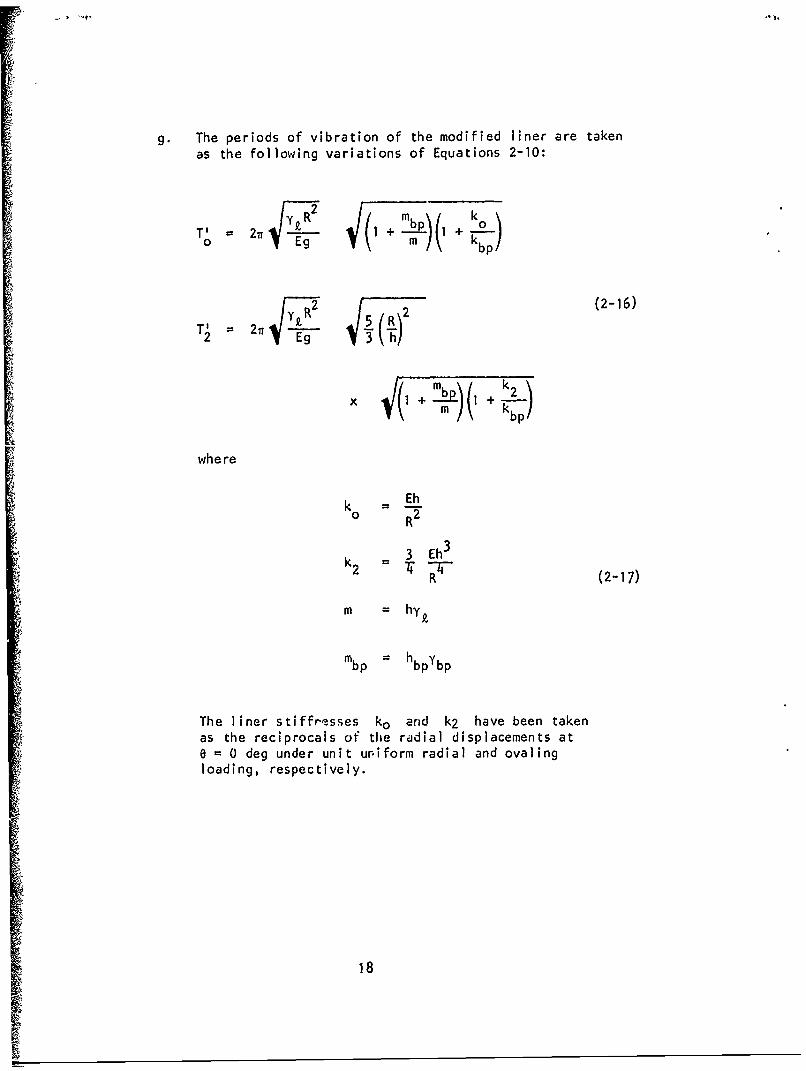
g. The periods of vibration of the modified liner are takenas the following variations of Equations 2-10:
IT where
EhR'R
T'3 Eh+lk -I- (2-17)
Sm = hy#.
mbp hbpYbp
The liner stiffr~esses ko arid k2 have been takenas the reciprocals or" the radial displacements at
0 = 0 deg under unit uniform radial and ovalingloading, respectively.
i Eh
018
5
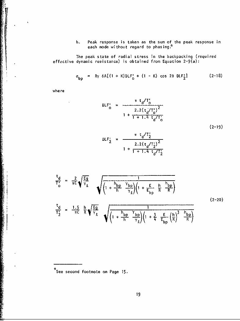
h. Peak response is taken as the sum of the peak response ineach mode without regard to phasing.*
The peak state of radial stress in the backpacking (requiredeffective dynamic res~istance) is obtained from Equation 2-9(a):
0bp = Ry 6A[(I + K)DLF' + (I - K) cos 26 DLF'] (2-18)
where
Tr td/T•DLF' d 0
0 2.2(td/T') 2
+ d o1+ I + 1.4 "t'd/TO'
(2-19)
I td/T2DLF' 2
2.2(td/T21)2
* ~1+1 1 + 1.4 td/T'
td~~~ 22~
td 1.cond 1
i h YZ EbpR R
See second footnote on Page 15.
19
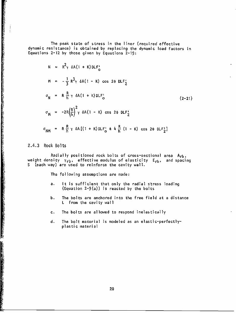
The peak state of stress in the liner (required effectivedynamic resistance) is obtained by replacing the dynamic load factors inEquations 2-12 by those given by Equations 2-19:
N R 2y 6A(l + K)DLF'0
SM = - R3 y 6A(I - K) cos 28 DLF'3 2
R Fa = R y y 6A(l + K)DLF'N h10 (2-21)
M = -210- y 6A(1 - K) cos 28 DLF2
aNM R y 6A[(1 + K) DLF°, h - K) cos 26e
2.4.3 Rock Bolts
Radially positioned rock bolts of cross-sectional area Arb,weight density Yrb, effective modulus of elasticity Erb, and spacingS (each way) are used to reinforce the cavity wall.
The following assumptions are made:
a. It is sufficient that only the radial stress loading(Equation 2-9(a)) is reacted by the bolts
b. The bolts are anchored into the free field at a distanceL from the cavity wall
c. The bolts are allowed to respond inelastically
d. The bolt material is modeled as an elastic-perfectly-plastic material
20
4
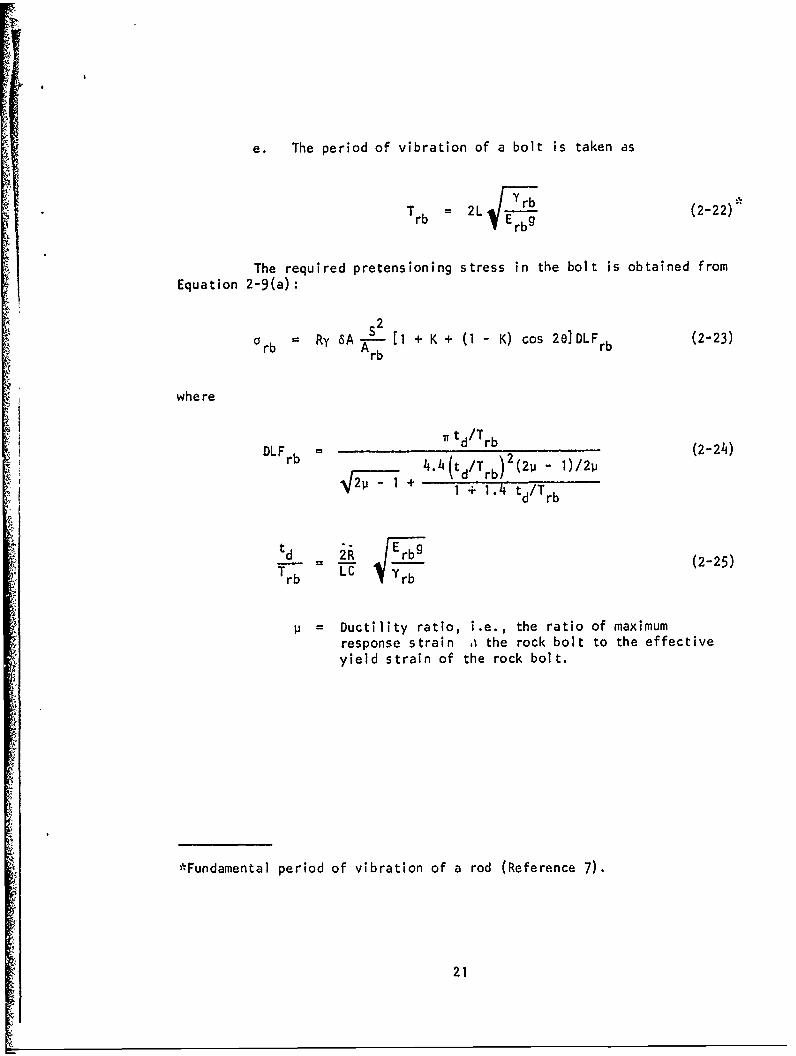
e. The period of vibration of a bolt is taken as
Trb = 2L -Yrb (2-22)E rbg
The required pretensioning stress in the bolt is obtained fromEquation 2-9(a)
rb Ry 6AA tb2 I + K + (1 - K) cos 2e]DLFrb (2-23)
where
I~~ t/rb
DLFb = (2-24)4.1(t/Tb)(211 - 1/)
S3/ - 1 + I + 1.4 td/Trb
Td -c r (2-25)
Tb -'rb
p =Ductility ratio, i.e., the ratio of maximumresponse strain o the rock bolt to the effectiveyield strain of the rock bolt.
*Fundamental period of vibration of a rod (Reference 7).
21
The length of the rock bolt must satisfy some minimum-lengthcriterion. Just what this minimum length should, be is not at all clear.However, judging from the load durations involved, it would appear thatthe rock bolt must have a length of 4R, where zero resistance isrequired at the outer anchor point and full resistance is required atthe cavity wall. It may be tentatively assumed that it is sufficientto provide a rocK bolt length of 2R, with full resistance over theentire length.
2.5 DESIGN PROCEDURE
The following inputs are assumed to be known:
a. Free-field ground shock stress, velocity, and accelera-tion histories
b. The stress ratio K behind the ground shock wave front
c. The effective propagation velocity C of the groundshock
d. The weight density y of the rock
e. The cavity radius R
The following procedure can be used to determine the designparameters of the cavity reinforcement:
a. Calcuiate the engulfment time of the cavity: te = 2R/C.
b. Incremental ize the free-field ground shock accelerationhistory into a succession of constant acceleration stepsof duration 2t as illustrated in Figure 2- 8 (a).
c. Construct an incremental free-field acceleration historyas shown in Figure 2-8(c). Assune that this history isan envelope history of peak response for use in thestate-of-stress equations derived for the reinforcement.
22
d. Select trial values of the reinforcement design parameters:
1. Liner: h, E, y
2. Backpacked liner: h, E, y£, hbp, Ebp, Ybp
3. Rockbolts: Arb, S, L, Eb, Yrb' I
e. Calculate the state of stress in the reinforcement usingthe applicable set of equations given in Section 2.4with the envelope 6A history constructed in Step c.
f. Calculate the quasistatic stress history of the rein-forcement that arises from the normal interaction of thereinforcement with the free-fleld ground shock and over-burden loadings.
g. Add the stress histories calculated in Steps e and f.
h. Compare the peak stresses found in Step g to the allow-able dynamic resistances of the reinforcement."*
i. Reiterate Steps d through h until an acceptable state ofstress is obtained.
If the stresses arising from the rigid-body acceleration of the rein-forcement itself are not negligible compared to those in Steps f and g,then they must also be taken under consideration. Also, the bucklingresistance of liners must be considered.
23
I
2.6 DISCUSSION
The following assumption was made at the outset of thisinvestigation:
The entire interaction zone of the cavity is cut by severalsets of planes of weakness of negligible tensile strengthin such a fashion that (1) the characteristic dimensionsof the blocks of rock are small compared to the cavityradius and (2) the blocks of rock are not wedged to oneanother.
Although this assumption was made so that the required restrainingstress would be a function of only uniform and ovaling components--afamiliar loading condition to the designer--it is very likely to beapplicable to a real-life design situation. However, in cases wherethe assumption is not valid and the failure tendency is more irregular,e.g., where a single column of unwedged rock exists at the O-deg"azimuth, the same general solution technique can be followed after themore or less discontinuous restraining stresses are expanded in aFourier series with respect to 8.
It was necessary to restrict the liner and backpacked linerto elastic response since it was not obvious during the course of thisinvestigation just how inelastic deformation could be rationallyhandled. Further study of this problem may prove fruitful and should beundertaken. It should be noted, however, that the requirement forelastic behavior may not be an unrealistic design goal, considering thelikelihood of an imposed multiple-attack threat (see Section 1.2).
The derived design requirements can also be used for cylindri-
cal cavities with noncircular cross sections--provided the deviationfrom circularity is not severe--by use of an equivalent circular cavity.In the case where the direction of ground shock propagation is not per-pendicular to the cavity axis, the component of the free-field groundshock acceleration that is perpendicular to the cavity axis should beused. It is suggested that this component not be less than K timesthe resultant acceleration.
24
Probably the mosc interesting 3spect of the results is thefact that the required stress resistance of the cavity reinforcement(e.g., Equation 2-11(e)) is : function of the magnitude of the cavityradius. Such a relationship nas been postulated to exist and has beenthe subject of much discussion since the Pile Driver shot. The rela-tionship obtained here is a simple linear dependence upon the magnitudeof the radius. This simple dependence is not inconsistent with thePile Driver data presented in Reference 2.
Another interesting aspect of the investigation is that lossof structural integrity of a cavity under dynamic ground shock loadingwas found to be dependent upon the rate of change of the free-fieldacceleration, a highly nebulous quantity today (1971), This dependenceis a fact of life and must be accepted.
The investigation presented here represents a first attempt atestablishing design requirements for reinforcement which functions toprevent mechanical failure of a cavity under dynamic loading. Valida-tion and assessment of the reliability of the design requirements willcome from both laboratory and field testing and from more rigorousanalytical investigations. Although a number of the assumptions madeduring the course of this investigation require more careful assess-ment, it is felt that there is sufficient validity underlying the inves-tigation to warrant interim adoption of the derived design requirements.
25
ASSUMED REGION OFPLANES OF WEAKNESS
I LLUM INATED /SHADOWREG ION R-EGIO-
GROUND SHOCK
(b)
FIGURE 2-1. MECHANICAL FAILURE OF CAVITY
26
w w
z
w
cc
27-
1.0 -
--- FAEE FMLD
,CAVITY RESPONSE
0.8-
S0.6.
40.-
-0.2
2K Al
0 to 20 30 1 50 s0 70 80t
0 AJA9I1
(a) FREE-SURFACE RADIAL VELOCITY AT 00
120. - -__________.___________________,________
I00'
280
60.
S10z
20-
o0 to 100 30o ;o 50 0 7o 80
AJA9I2
(b) FREE-SURFACE RADIAL DISPLACEMENT AT 00
FIGURE 2-3. TRANSIENT RESPONSE OF CIRCULAR CYLINDRICAL CAVITY TO PIECEWISELINEAR PULSE (REFERENCE 5)
28
4l
0.12
0.08-
o0.04.
-. 0-
-I MV -0.08,'i
- I
-0.12
l.• o io 40 Gs io 7'o i0
C- I
Ste •IJ913
-•'• (W FREE-SURrACE RADIAL, ACCELERATIOVIAT 0°
•)FIGURE 2-3. (CONTINUED)
o 29
I Kff
30
S•t
t = 2R111S• = 0.25
2 3
S• t/t<• e
00
(a) 0=900 ,r=R
= •• !FREE FIELD
-J
7L
(b) 0 = 90° r = R
III
0• t/t e 2 3
FIGURE 2-5. TRANSIENT ACCELERATION RESPONSE ON SHADOW SIDE OF
S~UNLINED CAVITY
~130(bit9,r
z0F-<•
-J
.. )
m (c) 0 = 1200, r =
0 1t/te 2 3
z0* I-
w-Jhi
I-J
z
0 1 t/te 2 3
FIGURE 2-5. (CONTINUED)
32
0 e
UU
150
'A, 3
F2 :E
2 - . ( o r U D
03
,.,•Z0 __ •FREE FIELD •
6A'N •N( (g) e =1800, r ,=R
2 3t/t
ILl
-J
ci€A'
-J
- (g) 6 1800 r - R
•.0*, r= R
* 0
o 1 2 3t/it
<C
cc 6 A ' 6[ 0 0, r" R
I-
0 2
t/t e
43.. • ma"-J2
0.5
I!I
0 ,2
o.40..$Ji
U'
0 0.3
S 0.2cq4
0.14.J
0~0 12
t/t e
FIGURE 2-6. PLOT OF TIME FUNCTION Q(t) (EQUATION 2-6)
p"
• 35
DIRECTION OFGROUND SHOCK ________________________
' PROPAGATION*
are
tM
AR
g FIGURE 2-7. LINER REINFORCEMENT
36
6A
IzzI
-2t (TYPICAL)
I. I I2tS~I I
w
o I I•-II
I TIME
I~FREE-FIELD ACCELERATION HISTORY
I6
I
I
IL
TIME
(b) CRITICAL INCREMENTS IN FREE FIELD ACCELERATION
ITM
(c)INRMNA FREE-FIELD ACCELERATION HISTORY
IIIi
CI TIH
II
FG) 2-ITICAO O ICREMENTSL FREE FIELD ACCELERATION SI 3- *' i
TIME
(C) INCREMENTAL FREE-FIELD ACCELERATION HISTORY
S~FIGURE 2-8. CONSTRUCTION OF INCREMENTAL FREE FIELD ACCELERATION HISTORY
37
SECTION 3
MATERIAL FAILURE OF CAVITY PENETRATIONS
3.1 INTRODUCTION
Hardened underground cavities must be penetrated at variouspoints to provide personnel and equipment access and utility connections(air, electrical, water, fuel, etc.) with adjacent cavities and with theground surface. The hardening of these penetrations to withstandmaterial failure of the rock is complicated by the fact that the pene-trating bore hole passes through the interaction field of the cavity, aregion much more severely stressed than the free-field region -in whichthe cavity and remote points of the penetration lie. In effect, thepenetrating bore hole is subjected to an enhanced free-field stress.
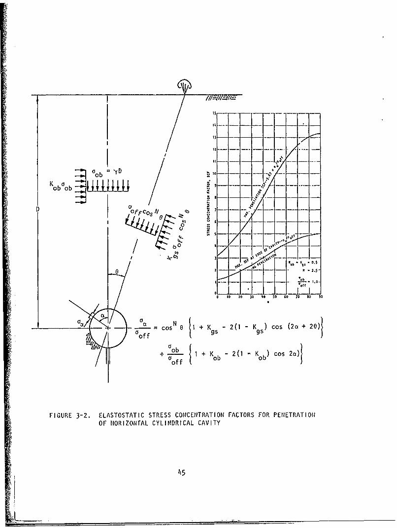
The criticality of the penetration problem is examined hereby calculating the inelastic response of a circular, cylindrical borehole which penetrates a horizontal, circular, cylindrical cavity. Thepenetrating bore hole is assumed to be radially directed. Althoughthis configuration of penetration and cavity may not be the most criti-cal one possible, it is the configuration that would be expected mostfrequently in practice. The three-dimensional penetration problem isrepresented by the two-dimensional configuration as shown in Figure 3-1.This idealization is a reasonable simplification when the diameter of
I the penetating bore hole is small compared to the cavity diameter andwhen the response of the cavity without penetration is essentially elastic.
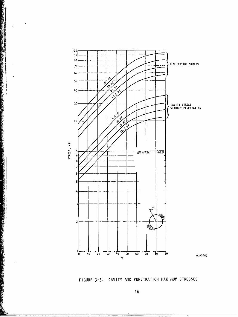
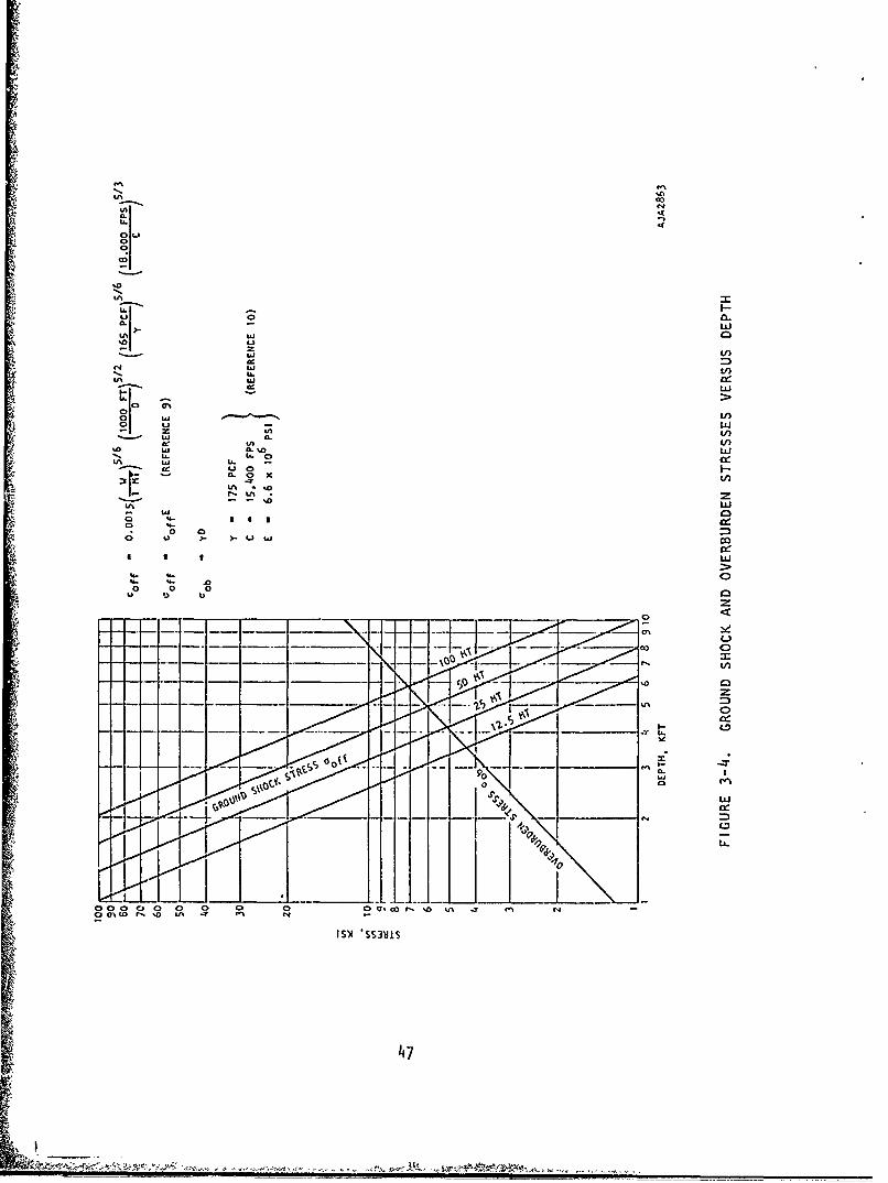
Before turning to the calculation of the inelastic responseat the penetration, it is of interest to calculate the enhanced freefield stress state for the penetration and the elastostatic response atthe penetration. These stress states are shown in Figure 3-2 in termsof elastostatic stress concentration factors (SCF). The cavity isassumed to be in a state of plane strain; hence, the loading of thepenetration in the direction of the axis of the cavity is 0.33 o/coff.Note that (1) the attenuation of ground shock stress is assumed tobe proportional to S-2.5, according to Reference 9, where S is theslant distance between the cavity and the point of burst, and (2) thedepth of burial is such that the vertical overburden stress aob isequal to the grourd shock stress for a direct overhead burst Oaff.The SCF's in Figure 3-2 are dimensionalized, as shown in Figure 3-3,using the overburden and ground shock stresses (Figure 3-4) for aschistose gneiss rock (Reference 10).
The results shown in Figure 3-3 clearly indicate the. relativeseverity of the penetration stresses with regard to material failure.Similar relative severities would also be obtained for other cavity
38
shapes, rock materials, definitions of ground shock stress, and othervalues of Oob/Ooff and K). Since the unconfined compressive strengthof rock at candidate sites ranges between, say, 20 and 35 ksi, onemight hastily conclude from these results that the solution to the pene-tration problem is simply to avoid penetration of a horizontal cylindri-cal cavity near the horizontal axis, say, between ±60 deg-from thehorizontal. This would indeed be a goal of the designer, but, unfor-tunately, this goal cannot always be met.
Hence, the penetration problem remains real and requiresinvestigation to determine its severity. The penetration problem hasbeen addressed here by way of an inelastic static analysis of a singlepenetration configuration subjected to repeated ground shock loading.The modeling shown in Figure 3-1 has been employed. Problem definitionand the method of solution are summarized in Section 3.2. The resultsand a discussion of the results are presented in Sections 3.3 and 3.4,respectively.
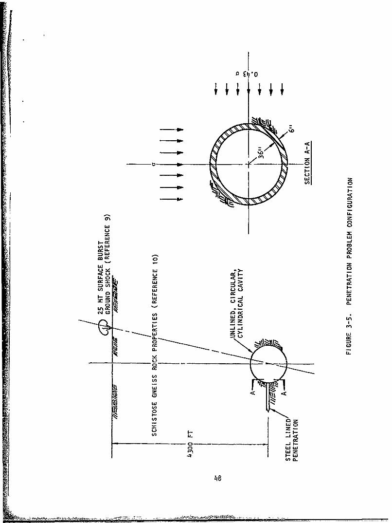
3.2 PROBLEM DEFINITION AND METHOD OF SOLUTION
The configuration studied is shown in Figure 3-5 and consistsof a steel-lined penetration at the springline of an unlined horizontal,circular, cylindrical cavity located at a depth of 4300 ft in a schistosegneiss rock mass subjected to a 25-MT surface burst. The penetrationliner, fabricated from 50,000-psi yield strength steel, is 6 in. thickand has a 72-in. internal diameter.
The vertical free field overburden and ground shock stressesapplicable for the cavity, each 5,000 psi, are taken from Figure 3-4.The response of the cavity is assumed to be elastic. The critical SCF'sfor the cavity at the point of penetration result from a direct overheadburst and are taken to be 2.5 and 0.43 in the circumferential and axialdirections, respectively. Under these conditions, the enhanced freefield environment for a transverse slice of the penetration at the cavitywall becomes 2.5 x 5000 = 12,500 psi overburden plus 2.5 x 5000 psi =12,500 psi ground shock in the vertical direction, and 0.43 x 5000 psi =2,100 psi overburden plus 0.43 x 5000 psi = 2100 psi ground shock in theaxial direction of the cavity. The penetration slice examined in theanalysis is assumed to be in a state of plane stress.
The response of the penetration slice to this enhanced free-field environment was calculated using a static, two-dimensional non-linear finite element computer program called INSTEP. Static applicationof the ground shock loading is quite reasonable for most combinationsof rock material, cavity size, and ground shock pulse shape encounteredin practice (Reference 5). Features of the code as app:ied to thepenetration problem include the following:
a. Use of constrained quadrilateral finite element special-ized for plane stress
39
b. Use of a midpoint rule of integration for the incremental
overburden and ground shock loading
C. Acceptance of nonlinear material property representationsincorporating yield criterion, flow rule, and bulk andshear moduli
d. Allowance for the addition or elimination of elementsand variations of the material properties of designatedelements during execution
Each of these features is discussed briefly in Appendix C.
The finite element mesh used in the computations is shown inFigure 3-6.
Material property data for the schistose gneiss were derivedfrom Reference 10 (see Appendix A). The following bulk and shearmoduli were obtained for both loading and unloading:
Bulk Modulus B = 5.5 x 10⁶ psi
Shear Modulus G = 2.5 x 10⁶ psi
The yield criterion adopted, shown in Figure 3-7, is consistent with thedata presented for the dry intact specimens of rock. The above proper-ties were assumed to be unaffected by the first or subsequent attack.
The bulk modulus, shear modulus, and yield criterion for thesteel liner were taken as:
B = 1.97 x 10⁷ psi
G = 1.185 x l07 psi
f = I' - 29,000 psi ; 0
The loading sequence was as follows:
Step (a)--In the absence of the steel liner, the enhanced freefield overburden stress was applied in 12 incremental steps.
Step (b)--The steel liner was emplaced.
Step (c)--The enhanced free field ground shock stress wasapplied in 16 incremental steps.
Step (d)--The ground shock stress was removed in 16 incrementalsteps.
Step (c) and (d) were then repeated four times.
40
3.3 RESULTS
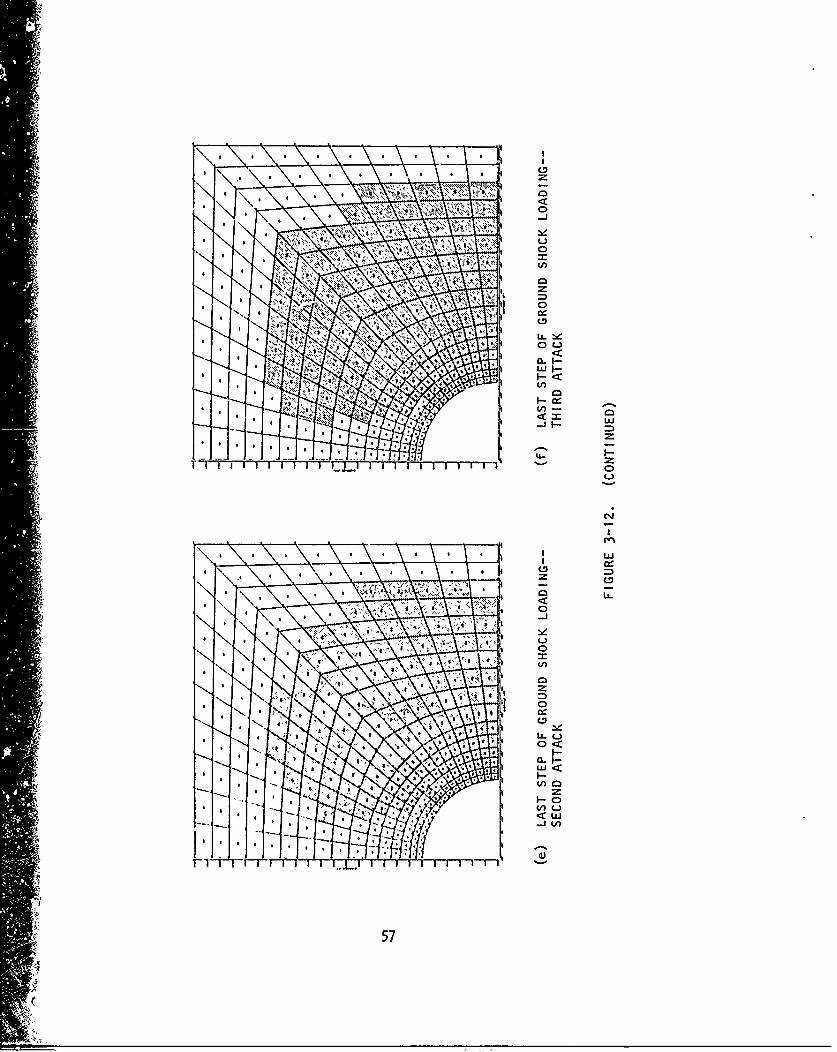
The results of the analysis are summarized in Figures 3-8 to3-12 and in Appendix B.
3.4 PHYSICAL INTERPRETATION OF RESULTS
The radial displacement at the penetration crown and springline(Figures 3-8 and 3-9) illustrate well the effects of liner reinforcementand repeated attack on material failure of penetrations. Considering thecrown displacement shown in Figure 3-8, the rock undergoes inelasticresponse under the overburden alone. The extent of the inelastic incre-mental response under the last increment of overburden loading is shownin Figure 3-12(a). After the steel liner is emplaced, the response toground shock becomes essentially elastic due to the confirement providedby the liner. It should be noted that the confinement increases thehydrostatic state of stress in the rock, and thus increases the effec-tive yield strength of the rock. Hence, some inelastic rock elementsrevert to elastic behavior upon further loading after confinement.Comparison of Figures 3-12(a) and 3-12(b) illustrates the effect ofliner confinement as seen by the reduction in the number of elementsundergoing inelastic incremental strain between the last increment ofoverburden loading and the first increment of ground shock loading. Atroughly 20-ksi loading, the liner begins to yield as seen by the devia-tion of the displacement curve from the elastic solution. At roughly22-ksi loading, the liner is yielded across its.thickness at the spring-line and thereafter offers a reduced restraint to the opening. Theextent of inelastic incremental response at the last loading incrementof the first attack is shown in Figure 3-12(c). The growth of inelasticincremental response for each loading increment from first applicationof overburden to the last increment of the first attack ground shock canbe traced in the figures contained in Appendix B.
Unloading of the first attack ground shock occurs virtuallyparallel to the loading branch, where the liner response was elastic(see Figure 3-8). Examination of the solution printout shows that theliner immediately unloaded, and continued to unload, elastically, whilethe rock unloaded inelastically. The extent of the inelastic incrementalresponse for the last increment of unloading is -hown in Figure 3-12(d)*.The rock which experiences inelastic response diring this last unloadingincrement can be thought of as a region of locked-in "plastic stress."In the absence of the liner, it is believed that the rock would haveunloaded elastically and, thus, would not have exhibited this region of"locked-in" stress.
The islands of incremental elastic response shown in Figure 3-12(d) arebelieved to result from the inherent inaccuracy in determining whetherthe yield criterion is satisfied. Execution of the problem with smallerload increments would reveal if this is indeed the source of these islands.
41
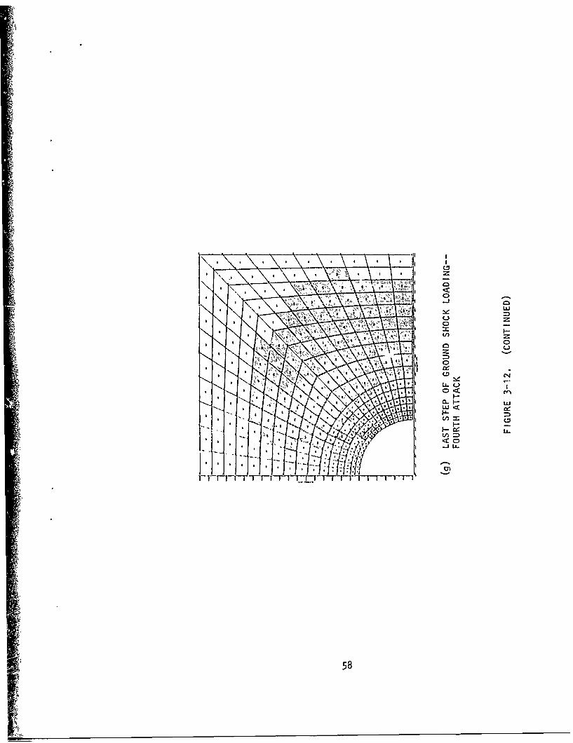
Repeated attack produces additional permanent displacement(Figures 3-8 through 3-11). The extent of the inelastic incrementalresponse for the last load increment of the second, third, and fourthattacks is shown in Figure 3-12(e) to (g). The additional permanentdisplacements appear to be real judging from their large magnitudes.It would appear unlikely that these large increments in displacement
would be due to solution accuracies and/or the encroachment of theyielded rock boundary on the mesh boundary. The seemingly erraticgrowth increments could be due to solution inaccuracies, as notedearlier. Unfortunately, the problem had to be terminated before itcould be determined if the growth was in the process of stabilizing,or would continue its erratic growth, or was dying out.
3.5 IMPLICATION OF RESULTS IN DESIGN
The results presented above have two unmistakable implicationsin design, namely:
a. Steel-lined penetrations can be adequately and cost-effectively designed to withstand repeated attack withlarge-yield weapons, provided that there is no significant:deterioration in rock strength with each attack
b. The analysis technique used here, the INSTEP Code, or anequivalent technique, can be effectively used today by thedesigner, provided material property parameters areavailable
Although a single penetration configuration has been examined, it is con-cluded that adequate penetration designs can be prov,:.. for threats andsites of current interest, except f(,- the effects of a deterioration inrock strength. Assuming as a worst case for the configuration examinedthat each attack after the first produces a 0.1-in. reduction in thepenetration radius, an 8-percent reduction in the cross-sectional area ofthe penetration results after ten 25-MT bursts. Even allowing for con-siderable error or change in the configuration parameters would stillresult in a closure that could be tolerated or compensated for. Sincethe rock material considered has an uncommonly low unconfined compressivestrength compared to what would normally be sought for candidate sites,the generalization of this example would tend to be on the conservativeside. Thus, the feasibility of penetration design, in general, hingesupon the favorable performance of the rock under repeated loading.This aspect of the problem can be easily incorporated in the analysistechnique simply by changing material parameters after each attack, oncematerial property parameters have been defined for repeateu ioading.
42
In order that a sophisticated analysis tool have utility incomplex design, it is necessary that the tool yield useful design infor-mation that is easily given physical interpretation. The INSTEP Codeused here, or an equivalent code, provides this utility as evidenced bythe useful and easily interpreted results obtained in this study. It isof interest to note that the execution time for this problem through thecompletion of four "dynamic" load cycles was 1-1/2 hr on a UNIVAC 1108computer.
h
S143
IJ
CAVITY
PENETRATION
FREE-FIELD' FREE-FIELDSTRESSES STRESSES
(a) THREE-DIMENSIONAL PROBLEM
INTERACTION STRESSES OFCAVITY WITHOUT PENETRATIONAT POINT OF INTERSECTIONOF PENETRATION AND CAVITY
(b) TWO-DIMENSIONAL MODEL
FIGURE 3-I. IDEALIZATION OF PENETRATION PROBLEM
44
I13
12
Ko-- -°--•-b 10
0ff~oofV
S+°o+
-.. 0
0 ffii0wr
0 to 20 30 46 50 60 10 to so
FIGURE 3-2. ELASTOSTATIC STRESS CONCENTRATION FACTORS FOR PENIETRATIOINOF HORIZONTAL CYLINDRICAL CAVITY
45
Lct a___ osN I+Ks2lKg)cs(2 0
70 _ PENETRATION STRESS
4 7 -60
50
WITHOUT PENETRATION
20/ -- ~** -,~
7 -
44
13
t0 10 20 30 40 50 60 70 80 go AJA2862
FIGURE 3-3. CAVITY AND PENETRATION MAXIMUM STRESSES
46
oAL4 0,
CA- w
ww
Li w
u -
'A w
U. U
0 ~ .ai
w I 0 0 i
o ~i ?~-Lc
* I I w
4- 4- 0
10.
00(0 o r- 'D0 Ln -7 m 0
IS~i 'SS3VJ1S
'47
Ft
DC
zz
wL ZL
AW ILI-
00 C0
w
LL.U
LUU
LiiCL
w 0:
0 ~ w
fn w
48.
Ii
-. - - - - - ---- - - --
*f, -6 S
AJA2868
FIGURE 3-6. FINITE ELEMENT MESH OF PENETRATION(SEE FIGURE 3-1)(b))
"49
Whe re
J 1 = I1 + 022 + 033
j 21 [(= - 022 )2 + (033 a 022 )2 +(033 -011211 1/2
J1 = -34,600 PSI
aI = 0.39
a 2 = 0.205
C1 = -2000 PSI
C2 = -8400 PSI
FIGURE 3-7. YIELD CRITERION FOR ROCK MATERIAL
50
D %90'0
%0
~~zizz
z0-
U-
C>,
I )4OViIV U313V
<
X <- _w cc
u
.J0.
w W6
LiL
j 0-W t4
OHS 0S O~flO 01313-33 030SNIHN
51
'ILV)7
tLli
8.LA.
I )13VLV U313
w
UJ 0.
I-- 3c
W C
LU -niS Nii
I - 0
co %D -7 C-
IS SSM alCo3J 3NIN
52 -
At
0 4-) LL.
o Io
uj U3~
Li i'
-Ujz
0 -LJ
I.--
4 Oj
< 2
00
C4I-
w
Ld)
4A0'NI 'LN3W3V~dIO II0-'
53- - - ~
00 co
- - U'
z
LI I_____ - - LA wi
LUJ
LAL
wi
0r 0
C4
0=LL.
40L
*Nl lN3W3V~dIO IIO-
54.--~
S I S * S S
:LC
r0ý
.0
11. V ~ II I i i 1()
(n
0
-C
wV) Aw
C.D,
IA 0
0 c'o
LILL
LiiL
55
LI)
tn w
cz
zc
-i U
56l (~
Vl
~~~~~~~L !Z \ * ~ g *
<CL
0
0<
< CD
Ulj)
57
Au
iI
It-
I-L
0)
58
SECTION 4
CONCLUSIONS AND RECOMMENDATIONS
4.' MECHANICAL FAILURE OF A CAVITY UNDER DYNAMIC LOADING
The following conclusions are worthy of restating: thesurvival of a cavity sited in well-fractured rock under dynamic loadingis linearly dependent upon (1) the increment of free-field ground shockacceleration occurring over a period of two cavity engulfment times and(2) the magnitude of the cavity radius.
The investigation presented represents a first attempt atestablishing design requirements for reinforcement which functions toprevent mechanical failure of a cavity under dynamic loading. Valida-
tion and assessment of the reliability of the design requirements willcome from both laboratory and field testing and from more rigorousanalytical investigations. Although a number of the assumpticns madeduring the course of this investigation require more careful assessment,it is felt that there is sufficient validity underlying the investigationto warrant interim adoption of the derived design requirements.
4.2 MATERIAL FAILURE OF CAVITY PENETRATIONS
The following conclusions are drawn from the study of materialfailure of cavity penetrations:
a. Steel-lined penetrations can be adequately and cost-effectively designed to withstand repeated attack withlarge yield weapons, provided that there is no significantdeterioration in rock strength with each attack.
b. The analysis technique used here, the INSTEP Code, oran equivalent technique, can be used effectively bytoday's designer, provided material property parametersare available.
The following recommendations are made:
a. The scope of laboratory test programs for determinationof material property parameters for rock materials shouldbe expanded to include routine determination of theeffect of repeated loading.
59
b. In order to gain further understanding of material failureof cavity penetrations and its implications in design,calculations of the nature performed in this study shouldbe continued and expanded in scope to include:
1. Consideration of other rock materials
2. Consideration of various liner thicknesses, includ-ing the unlined case for comparative purposes
3. Consideration of other burial depths and other insitu stress conditions
4. Additional loading cycles
5. Study of the effect of load increment and computa-tion&l mesh definition on solution accuracy
6. Simulation of the deterioration of strength of therock under repeated load cycles
c. A calculational program similar to that conducted hereshould be initiated to study the performance of lined(backpacked), horizontal, cylindrical cavities of circularand elliptical cross section under multiple attack, wheremechanical failure is assumed to be precluded.
60
REFERENCES
1. Distefano, C. J., et al., Experiments in Rock Bolting, Project
Officers Report--Project 3.7, Operation Flint Lock, Shot: PileDriver (U), POR-4515 (WT-4015), (AD 504523), Omaha District,Corps of Engineers, September 19, 1969 (SECRET).
2. Distefano, C. J., et al., Response of Tunnel Liners, ProjectOfficers Report--Project 3.1, Operation Flint Lock, Shot PileDriver (U), POR-4010 (\/T-401O), Omaha District, Corps of Engineers,November 23, 1970 (SECRET).
3. Agbabian-Jacobsen Associates, Hardened Facilities Design andVerification Test Study (U), SAMSO-TR-70-427, prepared for Spaceand Missile Systems Organization, November 1970 (SECRET).
4. Witt, E. F., and W. N. Butler, Cable Vulnerability Studies, ProjectOfficers Report--Project 3.8, Operation Flint Lock, Shot PileDriver (U), POR-4OI6 (WT-4OI6), Bell Telephone Laboratories, Inc.,December 31, 1969.
5. Bagge, C. F., and J. 14. Workman, Free-Field Ground Motion forBeneficial Facility Siting, Volume 4--Medium-Structure Interaction(U), SAMSO-TR-70-88, Joint Venture of Applied Theory, Inc., andAgbabian-Jacobsen Associates, June 197,, (SECRET).
6. Design of Structures to Resist Nuclear Weapons Effects, ASCEManual No. 42, 1964 Edition.
7. Timoshenko, S., Vibration Problems in Engineering, Third Edition,Van Nostrand, 1955.
8. FIugge, W., Stresses in Shells, Springer-Verlag, 1962.
9. Newmark, N. M., et al., Ditto Tab Test Planning (U),SAMSO-TR-68-288, Nathan M. Newmark Consulting EngineeringServices, October 1969 (SECRET).
10. Army Corps of Engineers, Missouri River Division Laboratory,Tests for Strength Characteristics of a Schistose Gneiss, FirstInterim Report, MRD Laboratory No. 64/126, May 1965.
61
APPENDIX A
MATERIAL PROPERTY PARAMETERSFOR PENETRATION CALCULATION
The sole source of material property data for the gneiss thatis represented in the present penetration calculation is Reference A-I.This reference provides quantitative data on the yield criterion andbulk and shear moduli, and it provides a qualitative indication thatdilatancy accompanies inelastic deformation.
A.1 BULK MODULUS
Although Reference A-I shows no results of hydrostatic loadingand unloading/reloading, information on the bulk modulus can be obtainedfrom the nominally elastic range of behavior in triaxial compressiontests. An ensemble of such data is plotted in Figure A-I in the formof mean stresi and volumetric strain. Each individual experiment has arange in which the inelastic shear deformation is negligible, and inthat range the P/p relation is about linear. In the absence of otherdata, a constant bulk modulus for the gneiss of
B = 5.5 x 10⁶ psi (A-i)
is indicated.
For the steel liner, B = 1.97 x 10⁷ psi.
A.2 SHEAR MODULUS
The shear modulus G is obtained from data on Poisson'sratio, v, and from the bulk modulus. An average value of Poisson'sratio for the gneiss of
v = 0.30 (A-2)
is a reasonable approximation for a number of triaxial compressionexperiments reported in Reference A-1. Assuming the material to havean elastic isotropic range, the shear modulus is
G = B 3(l-2v) = 2.54 x 10⁶ psi (A-3)2(1+v)
For the steel liner, G = 1.185 x 10⁷ psi.
62
A.3 YIELD CRITERION
Data on maximum combined stress is put in the form indicatedby the ideal!zed yield criterion in Figure A-2. The data shown inFigure A-3 appear to fall into four main groups. The solid lines,which are labeled f and f to indicate that they aF6 the yield1 2criteria for the present calculations, mainly represent dry specimensthat are either intact at the beginning of the experiment or that didnot fracture along joint planes. The dashed lines represent specimensthat were wet or prefractured or both. The highest reasonable yieldcriteria was selected for the present calculations. This implies thatprogressive deterioration of strength due to repeated loading isunaccounted for here. The yield criteria for the rock are as follows,where JA as defined in Figure A-2 is -34,600 psi.
J > - 34,600 psi
f = fI = + 0.39 J1 - 2000, psi < 0 (A-4)
J < - 34,600 psi
f = f2 = + 0.205 J- 840. psi < 0 (A-5)
The yield criterion for the steel is
f = - 29000. psi < 0 (A-6)
- 63
L. __
I
A.4 REFERENCES
A-I. Tests for Strength Characteristics of a Schistose Gneiss, FirstInterim Report, MRD Laboratory No. 64/126, Corps of Engineers,U. S. Army, Missouri River Division Laboratory, Omaha, May 1965.
64
I -,a I
U
I, *
- - .- - - -- - - - - - - - - - - - 0* Cd
1 _ _ 0
-N 0U. I -�
I-, - ---- t 0o
-JI U.
C (�)0
- - - - - - - - - - - - - - - - - 0
oU. T
I Cd
*� Ij�t
z- - - - - - - - - LUI-
Cd'?0
z 0o2 Li..
N' - - - - - ----- - - - - --- - - - - - - ,, I-.'C
-� c�-J w� U')
- Ci)
-J0
o 0-- ,-- 0
- - - - - - - - - _ _ 40 8_ _ -J
NO -4. 0
K.,, o
----- 8g 40 - I
w
- - ----
2 0 Li..0
� OC0�� - - - - - - - - - - - - .4- - -C -. %..%-- -
- ------------- - - - - - 0
------
0- .40310 - - - - ------ - 0
� .C C�O - Cd 0
I$�i 4
65
L. ______
<
&
f l (J1<o)
Where
J I cr 1 1 + a'22 + a 33
12 6 11i - 02) + (o033 022) (+ 3 c10
FIGURE A-2. DEFINITION OF YIELD COEFFICIENTS
66
28
26
R YDRY INTACTWET JOINTED
24 v DRY JOINTED* DRY JOINTED BUT DID NOT
FAIL ON JOINT PLANE22 U WET JOINTED BUT DID NOT -,
I FAIL ON JOINT PLANE
18
S10
2 Z
"0 5 10 15 20 25 30 35 40 45 50 55 60 65 70 75 80
KSI AJA2844
FIGURE A-3. YIELD CRITERIA USED FOR PENETRATION CALCULATION
67
APPENDIX B
GROWTH OF INELASTIC RESPONSE IN THE VICINITY OF ACAVITY PENETRATION THROUGH FIRST GROUND SHOCK APPLICATION
68
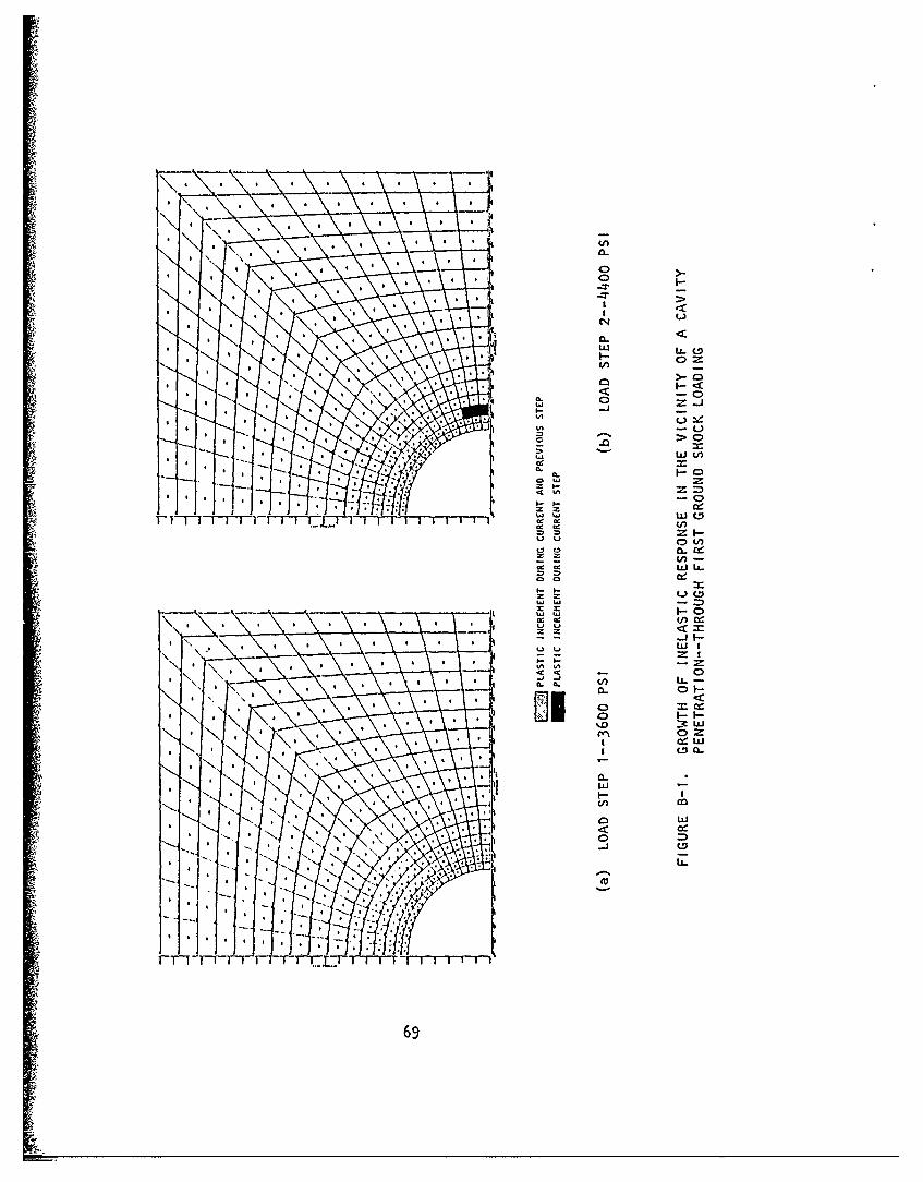
V 0 0
-w-Lw
WLJV)
CL.
rF~~~1Th~vWm %. 'i WC
in-cc ~ La U
a cc
(n w
WiIvv %nzI
CL Q.
41 W
FT1 TF -- -I~Tr~FT TrT r
69
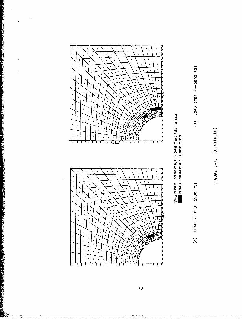
a w-
cc a-
In-
I-o
W w
700
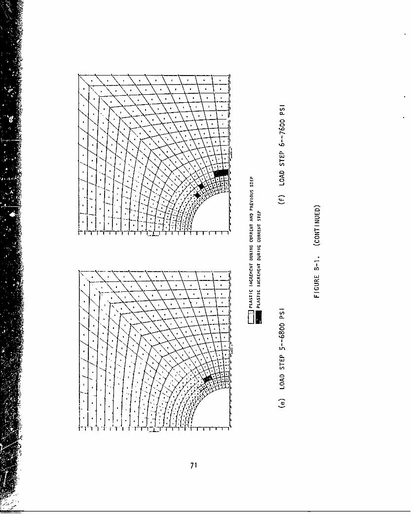
CLI
4-
( 0
LI)I
cc w
LL.
aa
LiA-
a..IJYQI
* :71
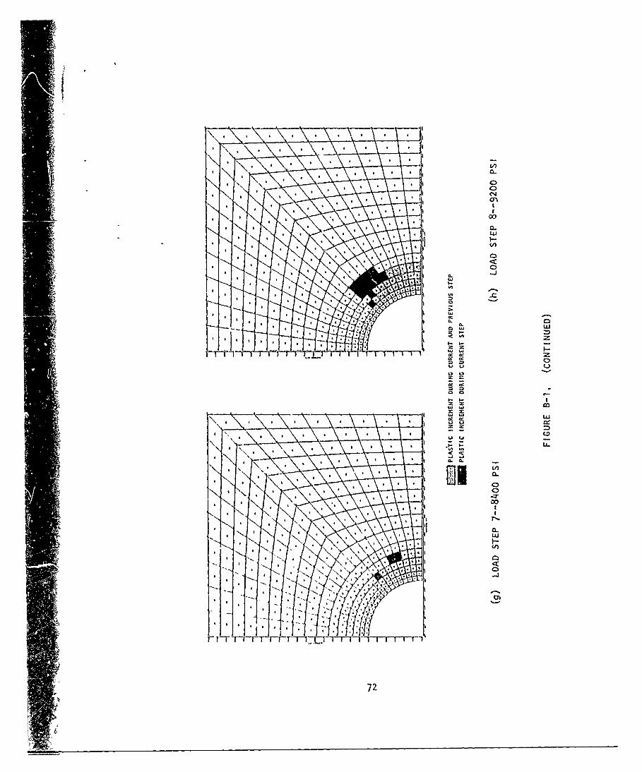
C1
aN
000
LU w
cc 00
L5 t
Q C2-
I-I- o
9 LL
* ricuo-LuO
72
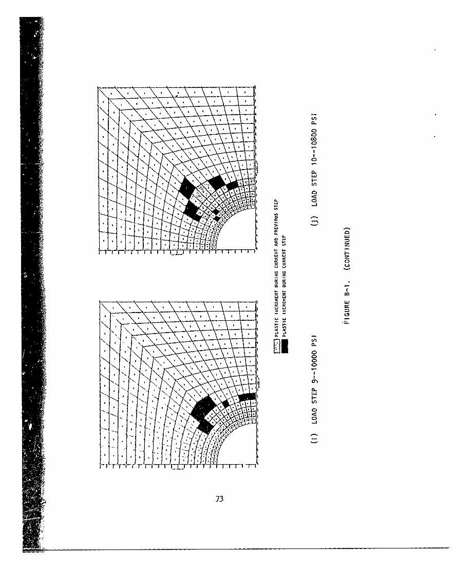
CL
a
I-I
IJLLI
C, (A
73
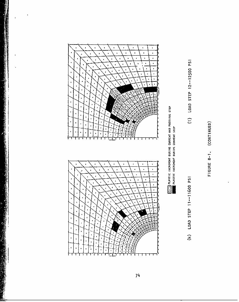
C)LA
CLt
cc.0 w~
w wx !i I-
be cc
-T--=
740
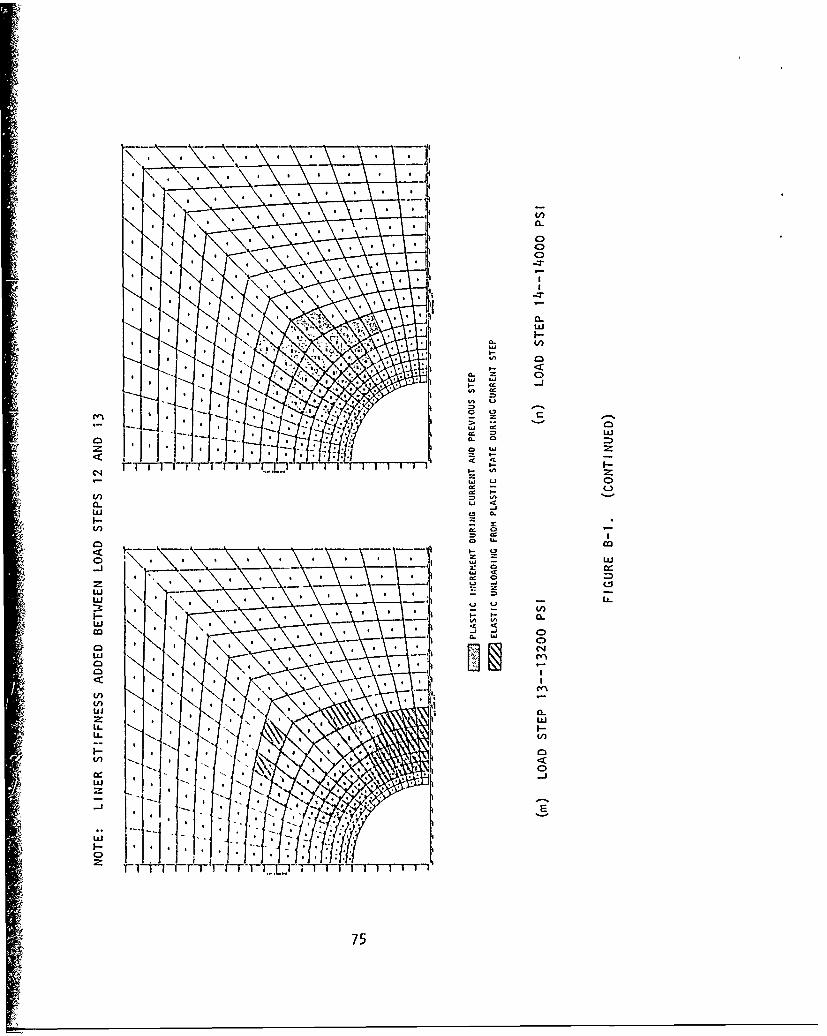
lk,
CIC
C0EUc0W
0-
0. Lt-
w C, -
w - e)
U) U
w
75-
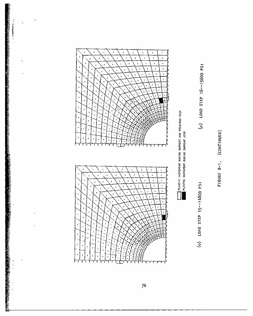
1LU
LU
-LJ
,5 C
76I -
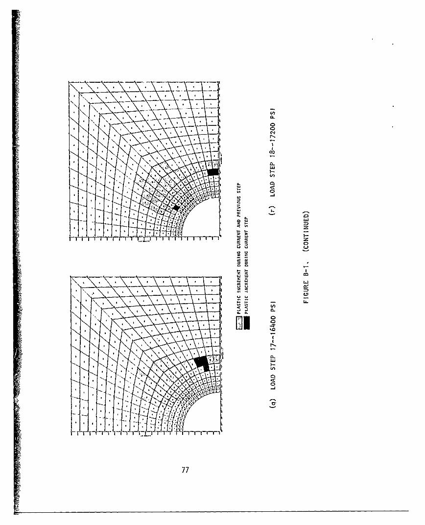
4V:
iC
* * * 0 0
Luj
LD C3
'0'In
4 4 0/)
in 0 -J
4 77
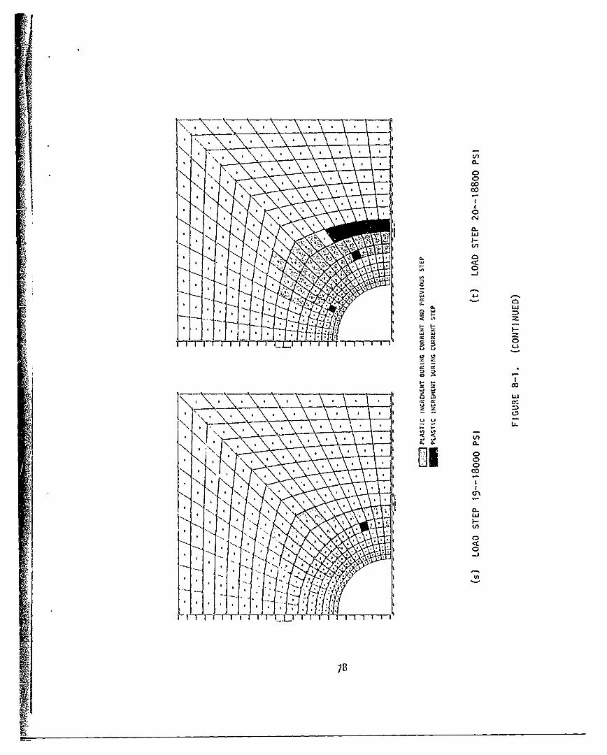
0-
20
0-
w wIz X-
C,,
00
CC
4L)
1-17-
78z
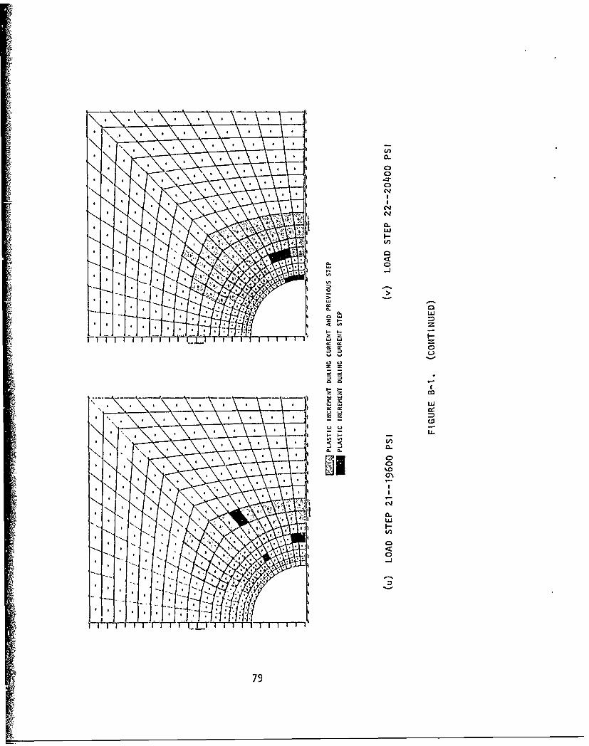
C1
S CS
wUIn-
cc00L
S S ~ *~'*~LL.
c. a.
79-
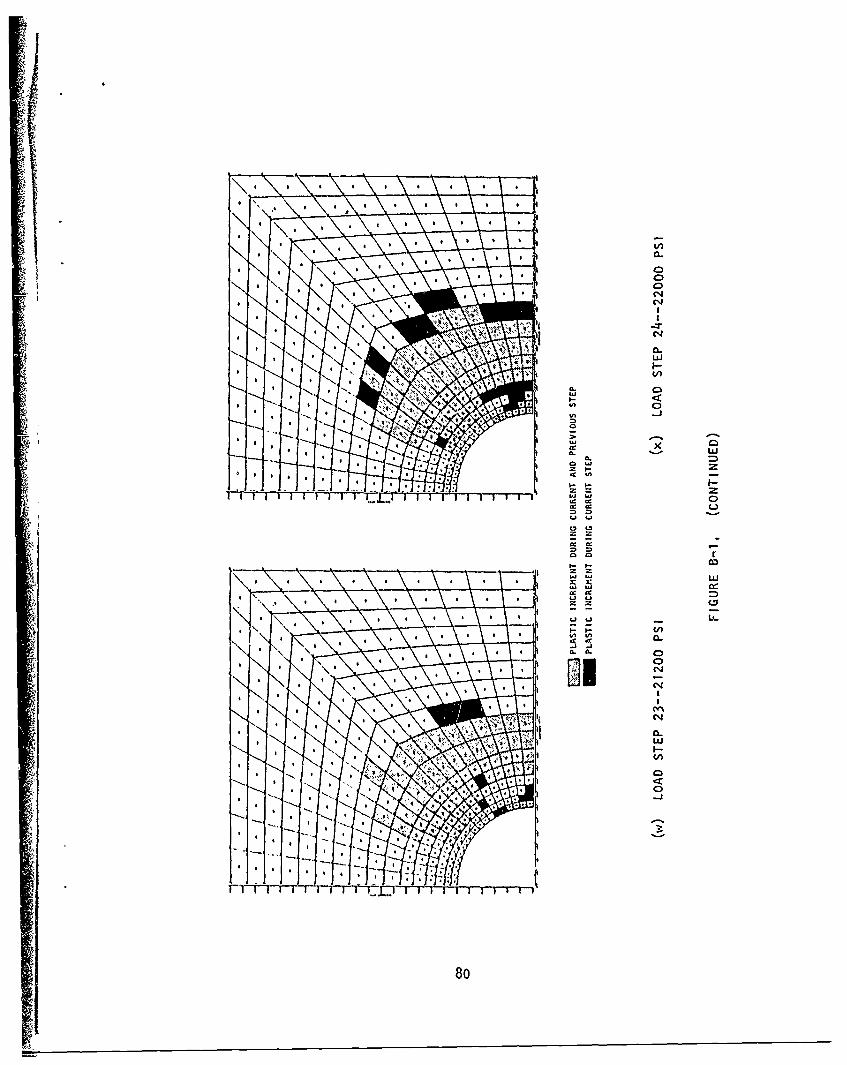
04
w w
IVt-r' cc 0
L)
on
04
Cw
80z
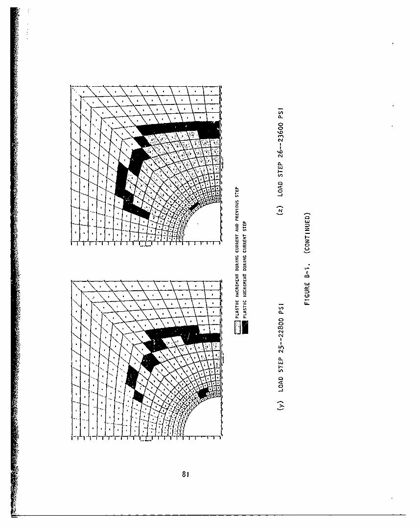
4-l
tni
0 U)
I-,-
00
a CN
81(
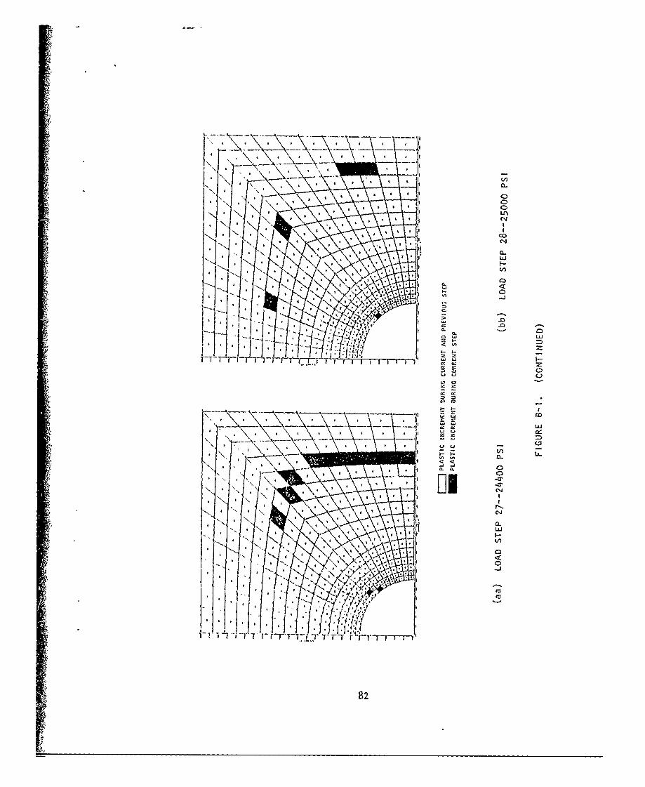
C>
CIS
c 1
0..F-
ILi
CLC
LL.
LZ 40l-J
w w CIO
A CL
82
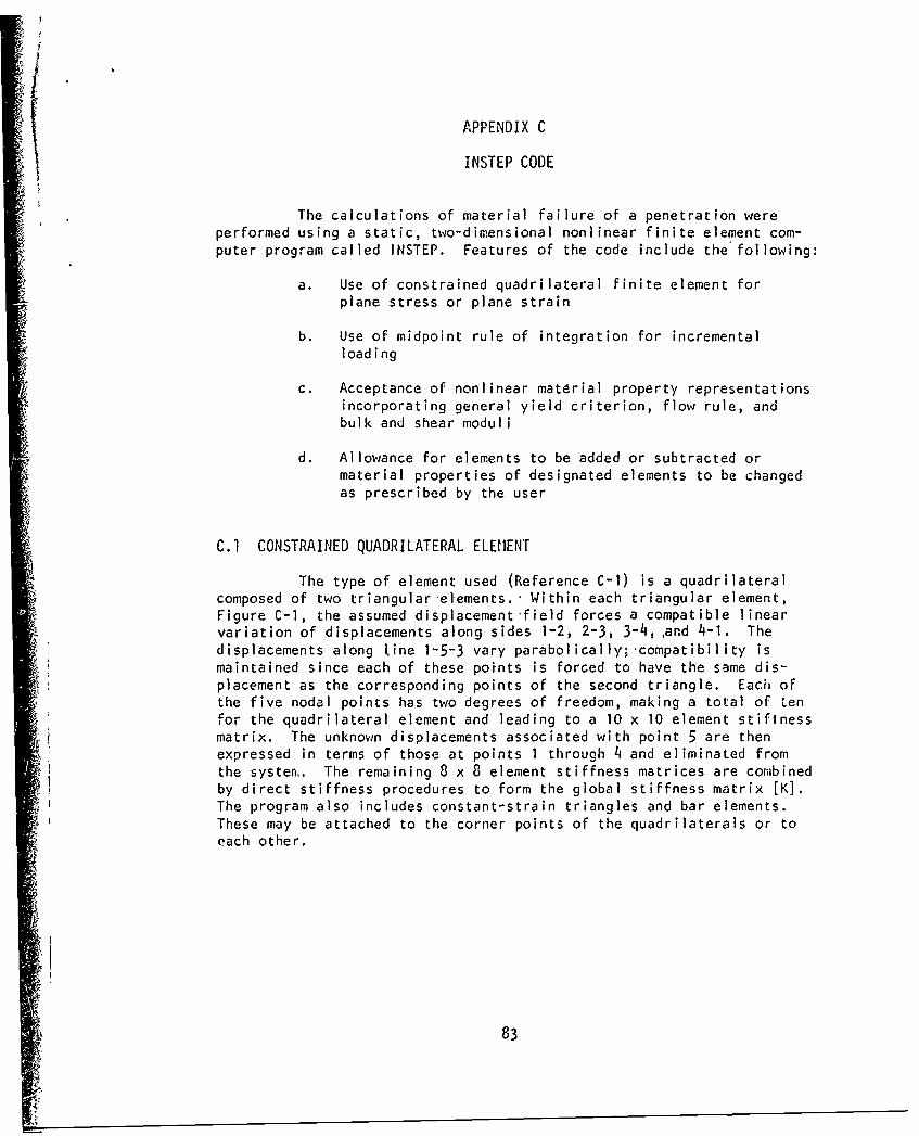
APPENDIX C
INSTEP CODE
The calculations of material failure of a penetration wereperformed using a static, two-dimensional nonlinear finite element com-puter program called INSTEP. Features of the code include the following:
a. Use of constrained quadrilateral finite element forplane stress or plane strain
b. Use of midpoint rule of integration for incrementalloading
c. Acceptance of nonlinear matdrial property representationsincorporating general yield criterion, flow rule, andbulk and shear moduli
d. Allowance for elements to be added or subtracted ormaterial properties of designated elements to be changedas prescribed by the user
C.1 CONSTRAINED QUADRILATERAL ELEMENT
The type of element used (Reference C-i) is a quadrilateralcomposed of two triangular elements.' Within each triangular element,Figure C-I, the assumed displacement field forces a compatible linearvariation of displacements along sides 1-2, 2-3, 3-4,,and 4-i. Thedisplacements along line 1-5-3 vary parabolically; compatibility ismaintained since each of these points is forced to have the same dis-placement as the corresponding points of the second triangle. Each ofthe five nodal points has two degrees of freedom, making a total of tenfor the quadrilateral element and leading to a 10 x 10 element stifinessmatrix. The unknown displacements associated with point 5 are thenexpressed in terms of those at points I through 4 and eliminated fromthe systen. The remaining 8 x 8 element stiffness matrices are combinedby direct stiffness procedures to form the global stiffness matrix [K].The program also includes constant-strain triangles and bar elements.These may be attached to the corner points of the quadrilaterals or toeach other.
83
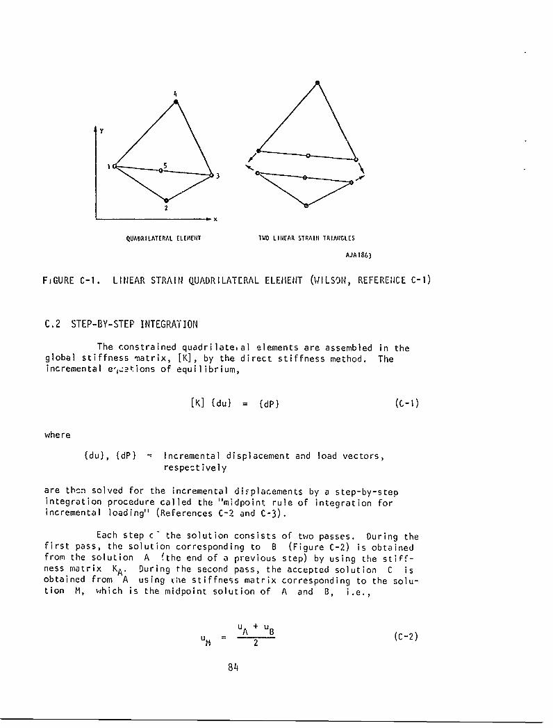
PX
QUADRILATERAL ELEHENT TWO LIIIEAR STRAIII TRIAINGLES
AJAI863
FIGURE C-1. LINEAR STRAIN QUADRILATERAL ELEHENT (WILSoN, REFEREN1CE C-1)
C.2 STEP-BY-STEP INTEGRATION
The constrained quadrilate,al elements are assembled in theglobal stiffness matrix, [K], by the direct stiffness method. Theincremental e' 1,.tions of equilibrium,
[K] {du} = {dP} (c-1)
where
{du), {dP( - Incremental displacement and load vectors,respectively
are thcn solved for the incremental diFplacements by a step-by-stepintegration procedure called the "midpoint rule of integration forincremental loading" (References C-2 and C'-3).
Each step c the solution consists of two passes. During thefirst pass, the solution corresponding to B (Figure C-2) is obtainedfrom the solution A (the end of a previous step) by using the stiff-ness matrix KA. During the second pass, the accepted solution C isobtained from A using vhe stiffness matrix corresponding to the solu-tion M, which is the midpoint solution of A and B, i.e.,
u A +uBum B B (C-2)
2
8 'i
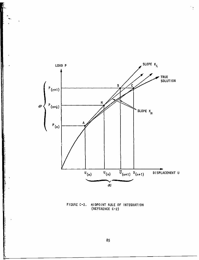
LOAD P SLOPE. K
TRUESOLUTION
e(n+l) B ..
dP P(n+j) SSLOPE Km
P (n) A
U(n) U(m) (n+l) U(n+l) DISPLACEMENT U
dU
FIGURE C-2. MIDPOINT RULE OF INTEGRATION(REFERENCE C-2)
85
-u---
C.3 MATHEMATICAL MODEL OF MATERIAL PROPERTIES
The mathematical model of material behavior used in the presentwork has the fol~owing basic features. A more complete description ofthe general model is given in Reference C-4.
C.. Bulk modulus (B) may be a function of the excess compres-sion v = p/po - 1, where p = current density*, andpo = initial density.
b. Shear modulus (G) may be a function of the current stateof stress.
(In the present study B and G are assumed to be constant.)
C. The yield zriterion may be a function of the first stressinvariant (J 1 ) and of the second invariant of stress!eviator (J0) (Reference C-5).
d. Work-hardening or strain-hardening rules prescribinghow the yield criterion may vary as a function of plasticwork or plastic strain may be used.
(In the present study, hardening is assumed to be zero, and the initialyield criterion is a permanent property of the material (Reference C-5).
e. A variety of flow rules prescribing how changes in plasticstrain are ,elated to changes in stress when the yieldcriterion is satisfied may be adopted.
(The plastic potential flow rule (Reference C-6) is used in the presentstLJY.)
lhis mathematical model must be expressed as a matrix ofcoefficients [C] relating stress increments [do} to strain increments{dc}.
{do} = [C] (de) (C-3)
The yield criterion for an isotropic material whose properties areinsensitive to temperature and strain may be expressed in terms of thestress invariants
6 0 (c-4)
86
where J 1 , J2, J5 = invariants of the stress tensor. Equation C-4represents the yield criterion for an ideally plastic material since thecriterion is a permanent pro'erty of the material and does not changewith loading history.
At the beginning of each load step, Hooke's law is tentatively
assumed to be valid as follows:
do.ij = (dekk) (6ij) + 2G (deij) ((C-5)
where
do.. = Stress increment tensorIi
de!. = Elastic strain increment tensorij
= Lame's parameter = B - 2.G
B, G = Bulk modulus, shear modulus
6ij = Kronecker delta (= 1 if I = j, = 0 if i 0 j)
Equation C-5 can readily be put in the form of Equation C-3. If thestate of stress
aij) new (oij)old I daij (c-6)
does not sati fy the yield criterion, i.e., if
f < 0 (C-7)
Equation C-5 correctly gives the stress increment. If the new state ofstress, considered as a trial state, exceeds the yield criterion,
f > 0 (c-8)
An explanation of Equations C-7 and C-8 is given in Reference C-7,Page 140.
87
I-
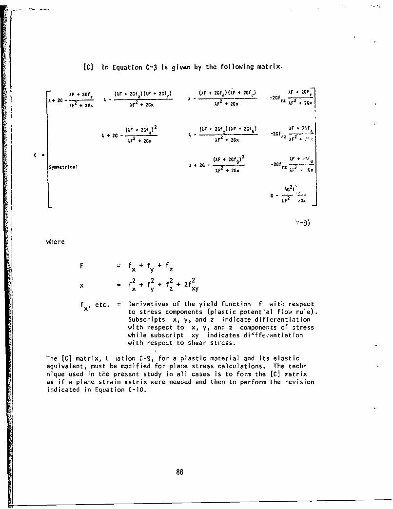
[C] in Equation C-3 is given by the following matrix.
IF + 2Gf (AF + 2Gf)(IF + 2Gf (AF + 2GfO) (OF + 2Gf I F + 2 Gf rI 2G - A A 2 A - -- = 2Gf 2
AFF2 + 2Gx F2 + 2 +2Gx F+'z F2G
(AF + 2Gf ) 2 WAF + 2Gf )(IF + 2Gfo) AF + 27fA- 2G -A2Gf z .
A -AF 2 + 2Gx AFl + 2Gx 77F2 + ,"
(AlF + 2Gf )2 XF+ 'I eSymmetrical A + 21 2 26rz
AF2 + 2Gx 1;F x
4G 2(o
G LF2 ,Gx
where
Ffx + fy + fz
2 2 2 2x f + f2 + f2 + 2f2)x y z xy
fx etc. Derivatives of the yield function f with respectto stress components (plastic potential flow rule).Subscripts x, y, and z indicate differentiationwith respect to x, y, and z components or stresswhile subscript xy indicates dilffesentiationwith respect to shear stress.
The [C] matrix, L iation C-9, for a plastic material and its elasticequivalent, must be modified for plane stress calculations. The tech-nique used in the present study in all cases is to form the [C] matrixas if a plane strain matrix were needed and then to perform the revisionindicated in Equation C-10.
88
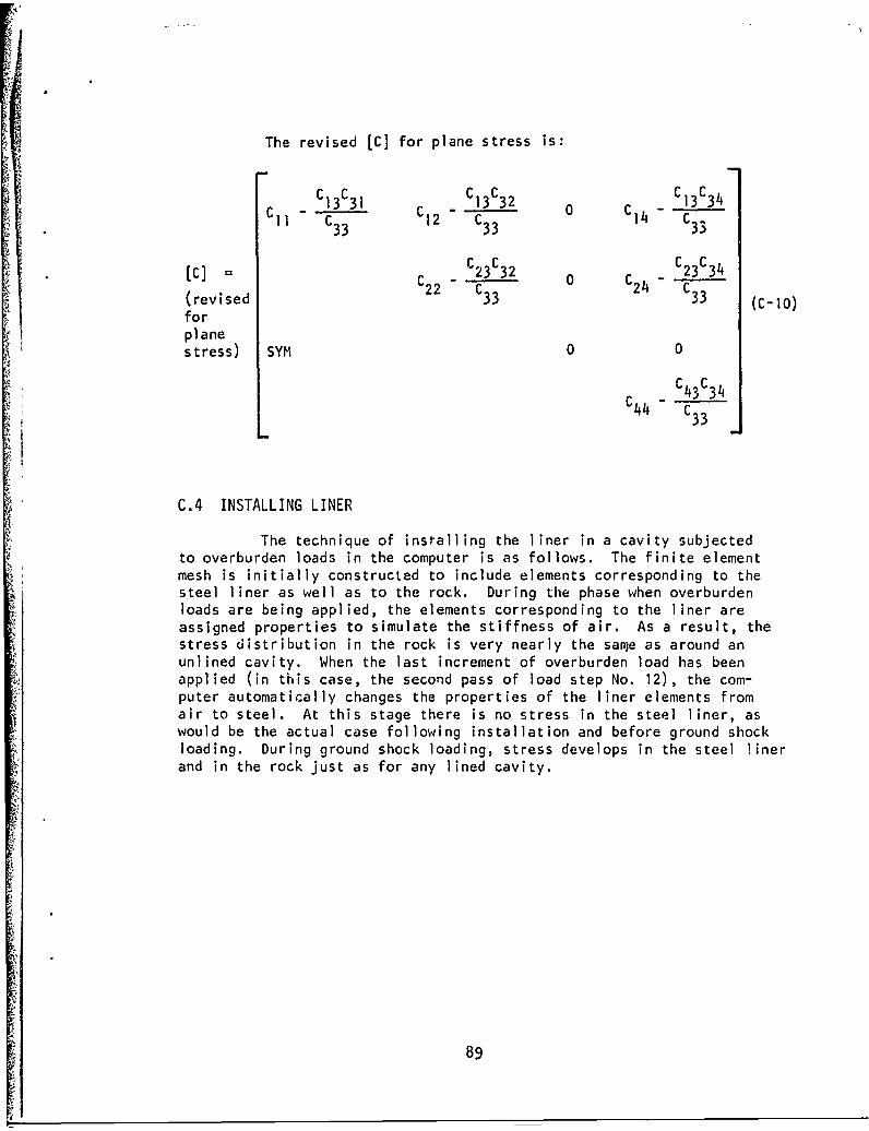
The revised [C] for plane stress is:
C 13 C31 C C13C32 C C C13C34C C33 C3 3 C3 3
[C] = C23C32 C 23C34
(revised 22 C3 3 24 C33 (C-10)forplanestress) SYM 0 0
C43C3 4C 44 C3C33
C.4 INSTALLING LINER
The technique of installing the liner in a cavity subjectedto overburden loads in the computer is as follows. The finite elementmesh is initially constructed to include elements corresponding to thesteel liner as well as to the rock. During the phase when overburdenloads are being applied, the elements corresponding to the liner areassigned properties to simulate the stiffness of air. As a result, thestress distribution in the rock is very nearly the san~e as around anunlined cavity. When the last increment of overburden load has beenapplied (in this case, the second pass of load step No. 12), the com-puter automatically changes the properties of the liner elements fromair to steel. At this stage there is no stress in the steel liner, aswould be the actual case following installation and before ground shockloading. During ground shock loading, stress develops in the steel linerand in the rock just as for any lined cavity.
89
C.5 REFERENCES
C-I. Wilson, E. L., A Computer Program for the Dynamic Stress Analysisof Underground Structures, Contract No. DACA 39-67-C-0020,University of California, Berkeley, January 1969.
C-2. Felippa, C. A., Refined Finite Element Analysis of Linear andNonlinear Two-Dimensional Structures, Structural EngineeringLaboratory Report No. 66-22, University of California, Berkeley,1966.
C-3. Adham, S. A., and J. A. Malthan, The Finite Element Method forInvestigating Edge Effects in the High-Explosive SimulationTechnique (REST), Project HEST Test V, Technical Report No.AFSWC-TR-68-26, Kirtland Air Force Base, New Mexico, pp. 124-125,1969.
C-4. Isenberg, J., et al., Spherical Waves in Inelastic Materials,DASA 2404, Defense Atomic Support Agency, March 1970.
C-5. Hill, R., The Mathematical Theory of Plasticity, Clarendon Press,1950.
C-6. Drucker, D. C., and W. Prager, "Soil Mechanics and PlasticAnalysis or Limit Design," Applied Mathematics, Vol. 10, No. 2,July 1952, pp. 57-165.
C-7. Fung, Y. C., Foundations of Solid Mechanics, Prentice-HallInternational Series in Dynamics, Englewood Cliffs, New Jersey,1965.
9
90
DISTRIBUTION LIST
No. of Copies
(Number of Copies of Report Shown in Parentheses) Form 1473
Chief of Research and Development; Department of the Army;ATTN: CRDNCB, CRDSTI (1), CRDPES, CRDES (1); Washington,D. C. 20310 2
Chief of Engineers; Department of the Army; ATTN: CER (1),ENGAS-I (2), ENGAS-IL (1), ENGBR (1), ENGCE (1), ENGCW-E (2),ENGCW-EC (1), ENGCW-ED (1), ENGCW-EG (1), ENGCW-ES (1),ENGCW-RR (1), ENGCW-Z (1), ENGMC-D (1), ENGMC-DE, ENGMC-E (1),ENGMC-EA (1), ENGMC-ED (1), ENGMC-EP (1), ENGMC-ER (1),ENGMC-M (3), ENGMC-S (1), ENGME-E (1), ENGME-EF (1), ENGME-ER(1), ENGML-ET (1), ENGME-RD (2), ENGME-S (1), ENGML (1),ENGSA (1) 1
Division Engineers, U. S. Army Engineer DivisionsHuntsville (2) North Pacific (2)Lower Mississippi Valley (2) Ohio River (2)Missouri River (2) South Atlantic (2)New England (2) South Pacific (2)North Atlantic (Resume only) Southwestern (2) 1
Directors, U. S. Army Engineer Division LaboratoriesMissouri River (2) Ohio River (2FNew England (2) South Atlantic (1)North Atlantic (2) South Pacific (1)North Pacific (2) Southwestern (2)
District Engineers, U. S. Army Engineer DistrictsAlaska (2) New Orleans (2)Albuquerque (2) New York (2)Baltimore (2) Norfolk (2)Buffalo (2) Omaha (2)Charleston (2) Philadelphia (2)Chicago (2) Pittsburgh (1)Detroit (2) Port!lnd (2)Fort Worth (2) Rock Island (2)Galveston (2) Sacramento 1Huntington (2) St. Louis (2)Jacksonville (2) St. Paul (2)Kansas City (2) San Francisco (2)Little Rock (2) Savannah (2)Los Angeles (2) Seuttle (2)Louisville (2) Tulsa (2)Memphis (2) Vicksburg (2)Mobile (2) Walla Walla (2)Nashville (2) Wilmington
91
No. of Copies(Number of Copies of Report Shown in Parentheses) Form 1473
President; Mississippi River Ccnmission; CE; P. 0. Box80; Vicksburg, Mississippi 39180 (1)
Research Center Library; U. S. Army Engineer WaterwaysExperiment Station; P. 0. Box 631; Vicksburg,Mississippi 39180 (10)
U. S. Army Cold Regions; Research and EngineeringLaboratory; (USA CRREL); Hanover, N. H. 03755 (1)
U. S. Army Engineer School Library; Thayer Hall(Bldg. 270); Fort Belvoir, VirginiE 22060 1
Ballistic Research Laboraturies; ATTN: AMXRD-BD;Aberdeen Proving Ground, Maryland 21005 1
Coastal Engineering Research Center; ATTN: Library;5201 Little Falls Rd. N. W.; Washington, D. C. 20016 1
U. S. Army Engineer Nuclear Cratering Group; LawrenceRadiation Laboratory; P. 0. Box 808; Livermore,California 94550 1
DEPARTMENT OF THE AIR FORCE
Research and Applications Br.; ATTN: AF/Preer;Directorate of Civil Eng.; HQ USAF; Pentagon;Washington, D. C. 20030 1
Office of Director of Defense Research and Engineering;ATTN: Director Strategic Weapons; Room 3E129; Pentagon,Washington, D. C. 20301 1
Headquarters, SAMSO (AFSC); ATTN: MI..FI-Luedeking (1),XRTBN; Norton AFB, California 92409 1
SAMSO/DEE; ATTh. William A. Platt; AF Unit Post Office;Los Angeles, California 90045 1
DEPARTMENT OF THE NAVY
Naval Civil Engineering Laboratory; ATTN: TechnicalLibrary L31; Port Hueneme, California 93041 (1)
Naval Facilities Engineering Command; Navy Department;ATTN: William J. Bobisch, Chief Engineer; Washington,D.C. 20390 1
92
No. of Copies(Number of Copies of Report Shown in Parentheses) Form 1473
OTHER DOD AGENCIES
Advanced Research Projects Agency; ATTN: NuclearMonitoring Research Office; 1400 Wilson Blvd.;Arlington, Virginia 22209 1
Director; Defense Nuclear Agency; Washington,
D. C. 20304 (1)
Test Command; ATTN: TCDT-E; Sandia Base, NewMexico 87115 1
Administrator; Defense Documentation Center; CameronStation; (12), Building 5; Alexandria, Virginia 22314
Director of Defense Research and Engineering; ATTN:Assistant Director Nuclear Programs; Assistant DirectorStrategic Weapons; Technical Library; Washington, D. C.20301 3
OTHER GOVERNMENT AGENCIES
U. S. Bureau of Mines; ATTN: Leonard Obert, ScienceAdviser-Mining Research; Building 20, Denver FederalCenter; Denver, Colorado 80225 (1)
U. S. Bureau of Mines; ATTN: J. R. McWilliams, Divisionof Mining Systems; Washington, D. C. 20240 (5)
U. S. Bureau of Reclamation; ATTN: M. H. Logan, Chief,Geology and Geotechnology Branch; Bldg. 67, DenverFederal Center; Denver, Colorado 80225 (1)
U. S, Bureau of Reclamation; ATTN: D. L. Misterek,Code 1512; Bldg. 56, Denver Federal Center, Denver,Colorado 80225 (1); Mr. G. B. Wallace (1)
U. S. Department of Commerce; NOAA - National OceanSurvey Lake Survey Center; 630 Federal Bldg. & U. S.Courthouse; Detroit, Michigan 48226 (2)
California Dept. Water Resources; ATTN: L. B. James,Chief Geologist; P. 0. Box 388; Sacramento, California95802 (1)
California Dept. Water Resources; ATTN: J. A. Wineland,Chief, Design Branch, Div. of Design & Construction;P. 0. Box 388, Sacramento, California 95802 (1)
93
No. of Copies(Number of Copies of Report Shown in Fuientheses) Form 173
OTHER GOVERNMENT AGENCIES (Cont'd)
Federal Highway Administration; 400 Seventh Street,S.W.; Washington, D. C. 20591 (1)
Federal Highway Administration; Office of Research;ATTN: W. J. Halstead, Chief, Materials Division;Washington, D. C. 205)1 (1)
Highway Research Board; ATTN: Librarian; 2101Constitution Avenue N.W.; Washington, D.C. 20418 (i)
U. S. Geological Survey; ATTN: H. W. Olsen, EngineeringGeology Branch; 345 Middlefield Road; Menlo Park,California 94025 (1)
U. S. Geological Survey; ATTN: E. C. Robertson; AcornBldg.; 8001 Newell St.; Silver Spring, Maryland 20910(1)
Tennessee Valley Authority; ATTN: R. B. Connelly,Manager's Office, Engineering Design and ConLtruction;700 Union Bldg.; Knoxville, Tenn. 37902 (2)
Tennessee Valley Authority; ATTN: J. H. Coulson;300 Arnstein Bldg.; Knoxville, Tennessee 37902 (1)
FOREIGN OFFICE
Chief of Engineers; Department of the Army;ATTN: ENGME-AS; Washington, D. C. 20314 1
FOR FORWARDING TO:
AWRE; Foulness Island; Southend-on-Sea; Essex, England 1
Canadian Forces Liaison Officer (Engr); USAMERDL,Fort Belvoir, Va. 22060 for: Dr. N. B. 11utcheon;Canadian Joint Staff; Department of Transport; Div. ofBldg. Research, National C Research Council of Canada;Ottawa; Construction Engineer; Air Service Branch;Ottawa, Ontario, Canada 5
Nova Scotia Technical College; ATTN: Dr. G. G. Meyerhof,Dept. of Civil Engineering; Filifax, N.S., Canada
94
Au
No. of Copies(Number of Copies of Report Shown in Parentheses) Form 1h73
UNIVERSITY
University of California; ATTN: R. E. Goodman,Assoc. Prof., Dept. of Civil Engineering; 475 DavisHall; Berkeley, California 94720 (1)
University of California; ATTN: Lawrence RadiationLaboratory Technical Infcrmation Dept. L-3; P. 0.Box 808; Livermore, California 94550 (1)
University of California; Los Alamos ScientificLaboratory; ATTN: Report Librarian; P. 0. Box 166?;Los Alamos; N. Mex. 87544Colorado School of Mines; ATTN: John J. Reed, Dept.
of Mining Engineering; Golden, Colorado 80401 (1)
Cornell University; ATTN: G. A. Kiersch, Chairman;
Dept. of Geological Sciences; 125 McGraw Hall,Ithaca, N.Y. 14850 (1)
Colorado State University; Fooi.hills EngineeringResearch Stl...ivn; ATTN: Prof. K. S. Lane; Ft. Collins,Colorado ... (1)
Cornell rn.aversity; ATTN: Dr. D. A. Sangrey, Assoc.Prof., Dept. of Geotechnical Engineering; School ofCivil and Environmental Engineering; Ithaca, New 1,ork14850 (1)
Florida State University; ATTN: E. G. Henneke; Schoolof Engineering Science, Tallahassee, Florida 323u6 1
Harvard University; ATTN: Prof. A. Casagrande; PierceHall; Cambridge, Mass. 02138
Univeraity of Illinois; ATTN: E. J. Cording; 2221 CEBldg., Urbana, Illinois 61801 (1); R. B. Peck;2230 CE Bldg. (1)
University of Illinois; Dept. of Civil Engineering;ATTN: Dr. D. U. Deere (1); Dr. N. M. Newmark (1);Prof. A. J. Hendron, Jr. (1); Metz Reference Room,B106 C. E. Bldg.; Urbana, Illinois 61801 (1)
University of Illinois; Department of Geology; ATTN:Dr. F. A. Donath; Urbana, Illinois 61801 (1)
95
No. of Copies(Number of Copies of Report Shown in Parentheses) Form 1473
UNIVERSITY (Cont'd
SIowa State University; ATTN: L. V. A. Sendlein,Department of Earth Science; Ames, Iowa 50010 (1)
Louisiana State University; ATTN: Dr. 0. A. Nance,Consultant to RAND and DASA; P.o 0. Box 16006-LSU;Baton Rouge, Ia. 70803 1
Massachusetts Institute of Technology; ATTN: R. C.Hirschfeld, Room 1-330 (1); Asst. Prof. H. H.Einstein, Room 1-380 (1); Prof. W. F. Brace, Room54-720 (1); Cambridge, Mass. 02139
University of Minnesota; ATTN: Prof. C. Fairhurst;Dept. of Civil and Mineral Engineering; Minneapolis,Minnesota 551455 (1)
University of Missouri at Rolla; ATTN: Dr. N. B.Aughenbaugh, Chairman; Dept. Mining, Petr., & Geol.Engrg. (1); Dr. G. B. Clark; Director, Rock Mechanics& Explosives Pesearch Center (1); Rolla, Missouri 65401
University of New Mexico; Eric H. Wang Civil EngineeringResearch Facility; ATTN: Dr. E. Zwoyer; Dr. G. E.Triandafilidis; Mr. P. A. Abbott; Mr. D. E. Calhoun;P. 0. Box 188, University Station, Albuquerque, NewMexico 87106 4
City College of New York! Dept. of Civil Engineering;ATTN: Prof. C. A. Miller; New York, N. Y. 10031 1
Pennsylvaria State University; Dept. of ArchitecturalEngineering; ATTN: J. S. Futrick, Admin. Aide;101 Engineering "A" Bldg., University Park, Pa.16802 (1)
Pennsylvania State University; ATTN: R. Stefanko,Assistant Dean, Earth & Mineral Sciences ContinuingEducation; 110 Mineral Sciences Building; UniversityPark, Pa. 16801 (1)
Purdue University; School of Civil Engineering;ATTN: Prof. Wm. R. Judd; Lafayette, Indiana 49707(1)
South Dakota School of Mines & Technology; Departmentof Mining Engineering; ATTN: Dr. E. Hoskins (1);Prof. E. H. Oshier (1); Rapid City, South Dakota 57701
96
No. of Copies(Number of Copies of Report Shown in Parentheses) Form 14T3
UNIVERSITY (Cont'd)
Univc-ý-sity of Texas At Austin; Dept. of Petr. Engineering;ATTN: Dr. K. E. Gray; Austin, Texas 78712 (1)
Texas A & M University; Center for Tectonophysics;ATTN: Dr. Melvin Friedman (1); Prof. J. Handin,Director (2); College Station, Texas 77843
Texas A & M University; College of Geosciences; Centerfor Tectonophysics; College Station, ",_-xas 77843 (1)
Utah State University; Engineering 11&periment Station;ATTN: Dr. R. K. Watkins, Associate Director; Logan,Utah 84321 1
Virginia Polytechnic Institute; Mining EngineeringDepartment; ATTN: Lawrence Adler (1); Dr. C. Haycocks(1); Blacksburg, Va. 24060
INDUSTRY
The Aerospace Corporation; P. 0. Box 5866; SanBernardino, California 92408; ATTN: S. B. Batdorf,B2/2020; M. Watson; W. Pfefferle (1) 2
Analytic Services, Inc.; ATTN: Geo. Hesselbacher;5613 Leesburg Pike; Falls Church, Va. 22041 1
Applied Theory, Inc.; ATTN: Dr. J. Trulio; 1010 WestwoodBlvd., Los Angeles, California 90024 1
AVCO Systems Division; Research Library; 201 LowellStreet, Wilmington, Mass. 01887 1
Battelle Memorial Institirte; ATTN: Dr. R. W. YJ.ingensmith;505 King Avenue; Columbus, Ohio 43201 1
Bell Telephone Laboratories; ATTN: G. F. Weissmann,Room 1A-105A; Mountain Avenue, Murray Hill, N. J. 07974 1
Bell Telephone Laboratories; ATTN: R. W. Mayo;Whippany Road, Whippany, N. J. 07981 1
Boeing Company - MASD Library; ATTN: 23-99 R. E. Shippfor L. E. Fleishman; P. 0. Box 3955; Seattle, Washing-ton98124 1
97
No. of Copies(Number of Copies of Report Shown in Parentheses) Form 1473
INDUSTRY (Cont'd)
Boeing Company - ATTN: J. A. Blaylock, 2-5410, 8C-41;K. Levien, Orgn. 2-5511 M/S 89-70; Mr. H. G. Leistner,Aerospace Croup, Research Division, M/S 89-70; P.O. Box3999, Seattle, Washington 98124 3
Boeing Company; ATTN: Technical Library; P. 0. Box3999; Seattle, Washington 98124 1
Engineering Societies Library; ATTN: Howard Gordon;345 East 47th Street, New York, N. Y. 10017 (i)
General American Research Division; ATTN: Dr. L. B.Holmes; 7449 N. Natchez Avenue; Niles, Illinois 60648 1
LIBRARY, General Electric Company Space & RESD Divs.,ATTN: Mr. L. Chasen, Manager; P. 0. Box 8555;Philadelphia, Pennsylvania 19101
General Electric T34PO; ATTN: DASIAC; P. 0. Drawer QQ,Santa Barbara, California 93102
General Motors Technical Center; ManufacturingDevelopment /33/; ATTN: W. M. Isbell; Warrend,Michigan 48090
Gulf Radiation Technology; ATTN: H. R. Kratz;P. 0. Box 608; San Diego, California 92112 1
lIT Research Institute; 10 West 35th Street;ATTN: Document Library (1); Dr. K. E. McKee(1); Chicago, Illinois 60616
Lockheed Missiles & Space Company, ATTN: Dr. R. E.Meyerott/C. C. Old; P. 0. Box 504; Sunnyvale,California 94088 2
A J. L. Merritt, Consulting and Special EngineeringServices, Inc. (1); P. 0. Drawer 1206; Redlands,California 92373
Mueser, Rutledge, Wentworth & Johnston; ATTN: P. C.Rutledge; 415 Madison Avenue, New York, N.Y. 10017 1
NOAA Environmental Research Laboratories; ATTN:Dr. J. S. Rinehart; Boulder, Colorado 80302 1
•, f98
No. of Copies
(Number of Copies of Report Shown in Parentheses) Form 1473
INDUSTRY (Cont'd)
The RAND Corporation; ATTN: Dr. H. L. Brode; Dr. C. C.Mow; 1700 Main Street, Santa Monica, California 90406 2
Research Analysis Corporation; ATTN: Documents Library;Route 123; McLean, Virginia 22101 1
Sandia Laboratories; ATTN: M. L. Merritt, Dept. 9150;W. R. Perret, Division 9111; P. O. Box 5800, Albuquerque,N. M. 87115 2
Test Command, ATTN: TCDT-E; Sandia Base, New Mexico 87115 1
Shannon & Wilson, Inc.; ATTN: Dr. R. P. Miller; 1105N. 38th Street, Seattle, Washington 98103 (1); S. D.Wilson (1)
Southwest Research Institute; ATTN: R. C. DeHart;8500 Culebra Road; San Antonio, Texas 78228 1
Systems, Science & Software; ATTN: Document Control;P. 0. Box 1620; La Jolla, California 92037 1
TRW Systems (Rl/1138); ATTN: Norman Lipner; 1 SpacePark; Redondo Beach, California 90278 1
TRW Systems Group; ATTN: F. A. Pieper; P. 0. Box 1310,San Bernardino, California 92402 1
Paul Weidlinger, Consulting Engineer; 110 East 59thStreet, ATTN: Dr. M. L. Baron; New York, N. Y. 10022 1
Woodward-Clyde & Associates; ATTN: A. T. Harrigan,Librarian; P. 0. Box 24075; Oak-land, California 94623(1)
Woodward-Clyde & Associates; ATTN: R. L. McNeill;758 N. Batavia; Orange, California 92668 (1)
Woodward-Clyde & Associates, Inc.; ATTN: DennisLeary; 31 Orton Road; West Caldwell, New Jersey 07012(1)
Woodward-Lundgren & Associates; ATTN: C-Y Chang;P. 0. Box 24075; Oakland, California 94623 (1)
99