easiplus mi 3000 instruction manual - industrial … · metrel d.d. ljubljanska cesta 77 1354...
TRANSCRIPT
EasiPLUS MI 3000
Instruction manual Version 1.0, Code No. 20 750 977
2
Distributor: Manufacturer: METREL d.d. Ljubljanska cesta 77 1354 Horjul Slovenia web site: http://www.metrel.si e-mail: [email protected] © 2006 METREL
Mark on your equipment certifies that this equipment meets the requirements of the EU (European Union) concerning safety and interference causing equipment regulations.
No part of this publication may be reproduced or utilized in any form or by any means without permission in writing from METREL.
MI 3100 EasiPLUS Table of contents
3
1 Preface.......................................................................................................... 5
2 Safety and operational considerations...................................................... 6 2.1 Warnings and notes....................................................................................... 6 2.2 Battery ........................................................................................................... 9 2.3 Charging ........................................................................................................ 9 2.4 Charging of new battery or unused battery.................................................... 9 2.5 Standards applied........................................................................................ 10
3 Instrument description.............................................................................. 12 3.1 Front panel .................................................................................................. 12 3.2 Connector panel .......................................................................................... 13 3.3 Back panel................................................................................................... 13 3.4 Bottom view ................................................................................................. 14 3.5 Carrying the instrument ............................................................................... 15 3.6 Instrument set and accessories ................................................................... 16
4 Instrument operation................................................................................. 17 4.1 Meaning of symbols and messages on the instrument display .............................. 17
4.1.1 The online voltage and output terminal monitor.................................... 17
4.1.2 Message field – battery status .............................................................. 18
4.1.3 Message field – measurement warnings/messages ............................. 18
4.1.4 Result field............................................................................................ 19
4.1.5 Other messages ................................................................................... 19
4.1.6 Sound warnings.................................................................................... 19
4.1.7 Function and parameter line ................................................................. 20 4.2 Selecting measurement function / sub-function ........................................... 20 4.3 Setting measurement parameters and limits ............................................... 20 4.4 Setup menu ................................................................................................. 20
4.4.1 Supply system setup............................................................................. 21
4.4.2 Language selection............................................................................... 21
4.4.3 Recalling original settings ..................................................................... 21 4.5 Display contrast adjustment......................................................................... 22
5 Measurements............................................................................................ 23 5.1 Insulation resistance .................................................................................... 23 5.2 Continuity..................................................................................................... 25
5.2.1 LowΩ resistance................................................................................... 25 5.2.2 Continuity.............................................................................................. 25
5.3 Testing RCDs .............................................................................................. 29
5.3.1 Limit contact voltage............................................................................. 29
5.3.2 Nominal differential trip-out current....................................................... 29
MI 3100 EasiPLUS Table of contents
4
5.3.3 Multiplier of nominal residual current .................................................... 29
5.3.4 RCD type and test current starting polarity ........................................... 29
5.3.5 Testing selective (time-delayed) RCDs................................................. 30
5.3.6 Contact voltage..................................................................................... 30
5.3.7 Trip-out time ......................................................................................... 31
5.3.8 Trip-out current ..................................................................................... 33
5.3.9 Autotest ................................................................................................ 34 5.4 Fault loop impedance and prospective fault current .................................... 38
5.4.1 Fault loop impedance ........................................................................... 38
5.4.2 Trip-lock function .................................................................................. 39 5.5 Line impedance and prospective short-circuit current.................................. 41 5.6 Phase sequence testing .............................................................................. 43 5.7 Voltage and frequency................................................................................. 45 5.8 Testing PE terminal ..................................................................................... 47
6 Maintenance............................................................................................... 49 6.1 Replacing fuses ........................................................................................... 49 6.2 Cleaning ...................................................................................................... 49 6.3 Periodic calibration ...................................................................................... 49 6.4 Service......................................................................................................... 49
7 Technical specifications ........................................................................... 50 7.1 Insulation resistance .................................................................................... 50 7.2 Continuity resistance ................................................................................... 50
7.2.1 LowΩ resistance................................................................................... 50 7.2.2 Continuity.............................................................................................. 51
7.3 RCD testing ................................................................................................. 51
7.3.1 General data......................................................................................... 51
7.3.2 Contact voltage..................................................................................... 52
7.3.3 Trip-out time ......................................................................................... 52
7.3.4 Trip-out current ..................................................................................... 52 7.4 Fault loop impedance and prospective fault current .................................... 53 7.5 Line impedance and prospective short-circuit current.................................. 54 7.6 Phase rotation.............................................................................................. 54 7.7 Voltage and frequency................................................................................. 54 7.8 Online voltage monitor................................................................................. 55 7.9 General data................................................................................................ 55
8 Appendix A................................................................................................. 56 8.1 Accessories required for specific measurement .......................................... 56
MI 3100 EasiPLUS Preface
5
1 Preface Congratulations on your purchase of the EasiPLUS instrument and its accessories from METREL. The instrument was designed on basis of rich experience, acquired through many years of dealing with electric installation test equipment. The EasiPLUS instrument is professional, multifunctional, hand-held test instrument intended for all measurements performed for total inspection of electrical installations in buildings. The following measurements and tests can be performed:
q Voltage and frequency, q Continuity (LowΩ and continuity function), q Insulation resistance, q RCD testing, q Fault loop impedance, q Line impedance, q Phase sequence.
Wide graphic matrix display with backlight offers easy to read results, indications, measurement parameters and messages. Operation is simple and clear – operator does not need any special training (except reading this instruction manual) to operate the instrument. In order for operator to be familiar enough with measurements in general and typical applications, it is advisable to read Metrel handbook Measurements on electric installations in theory and practice. The instrument is equipped with all accessories necessary for comfortable testing. It is kept in a soft carrying bag together with all accessories.
MI 3100 EasiPLUS Safety and operational considerations
6
2 Safety and operational considerations 2.1 Warnings and notes In order to reach high level of operator’s safety while carrying out various tests and measurements using the EasiPLUS instrument, as well as to keep the test equipment undamaged, it is necessary to consider the following general warnings:
q symbol on the instrument means »Read the Instruction manual with special care«. The symbol requires an action!
q If the test equipment is used in a manner not specified in this user manual the protection provided by the equipment may be impaired!
q Read this user manual carefully, otherwise use of the instrument may be dangerous for the operator, for the instrument or for the equipment under test!
q Do not use the instrument and accessories if any damage is noticed!
q In case a fuse has blown follow the instructions in this manual to replace it!
q Consider all generally known precautions in order to avoid risk of electric shock while dealing with hazardous voltages!
q Do not use the instrument in supply systems with voltages higher than 550 V!
q Service intervention or adjustment procedure is allowed to be carried out only by a competent authorized person!
q Use only standard or optional test accessories supplied by your distributor!
q Consider that older and some of new optional test accessories compatible with this instrument meet only overvoltage category CAT III / 300 V! It means that maximal allowed voltage between test terminals and ground is 300 V!
q Instrument contains rechargeable Ni-Cd or Ni-MH batteries. The batteries should only be replaced with the same type as defined on the battery placement label or in this manual. Do not use standard batteries while power supply adapter is connected, otherwise they may explode!
q Hazardous voltages exist inside the instrument. Disconnect all test leads, remove the power supply cable and switch off the instrument before removing battery compartment cover.
q Do not connect any voltage source on CLAMP CURRENT input. It is intended only for connection of current clamp with current output. Maximal continuous input current is 30 mA!
q All normal safety precautions have to be taken in order to avoid risk of electric shock when working on electrical installations!
MI 3100 EasiPLUS Safety and operational considerations
7
Warnings related to measurement functions Insulation resistance
q Insulation resistance measurement should only be performed on de-energized objects!
q When measuring insulation resistance between installation conductors all loads must be disconnected and all switches closed!
q Do not touch the test object during the measurement or before it is fully discharged! Risk of electric shock!
q When an insulation resistance measurement has been performed on a capacitive object automatic discharge may not be done immediately! Warning message and actual voltage is displayed during discharge, until voltage drops below 10 V.
q Do not connect test terminals to external voltage higher than 600 V (AC or DC) in order not to damage the test instrument!
Continuity functions
q Continuity measurements should only be performed on de-energized objects! q Test result may be influenced because of parallel impedances or transient
currents! Testing PE terminal
q If phase voltage is detected on tested PE terminal, stop all measurements immediately and take care the fault is eliminated before proceeding with any activity!
Notes related to measurement functions General
q Indicator means that the selected measurement cannot be performed because of irregular conditions on input terminals.
q Insulation resistance, continuity functions and earth resistance measurements shall be performed on de-energized objects.
q PASS / FAIL indication is enabled when limit is set. Apply appropriate limit value for evaluation of measurement results.
q In case that only two of three wires are connected to tested electrical installation, only voltage indication between these two wires is valid.
Insulation resistance
q In case of voltage higher than 10 V (AC or DC) between test terminals, the insulation resistance measurement will not be performed.
Continuity functions
q If voltage between test terminals is higher than 10 V the continuity functions cannot be performed.
q Before performing continuity measurement compensate test lead resistance if necessary. The compensation is performed in LowΩ function.
MI 3100 EasiPLUS Safety and operational considerations
8
RCD functions
q The instrument indicates reverse polarity and disables measurement if L/L1 and N/L2 test leads (universal test cable) are connected in reversed way, or terminals of the tested wall socket are reversed.
q Parameter settings in one function are also kept for other RCD functions! q The measurement of contact voltage does not normally trip an RCD. However,
the trip limit may be exceeded as a result of leakage current flowing to the PE protective conductor or a capacitive connection between L and PE conductors.
q Trip-lock sub-function (function selector switch in LOOP position) takes longer to complete but offers much better accuracy of fault loop impedance result (in comparison with the RL sub-result in Contact voltage function).
q RCD trip-out time and RCD trip-out current measurements will be performed only if contact voltage in pre-test at nominal differential current is lower than the set limit contact voltage!
q The auto test sequence (RCD AUTO function) stops when trip-out time is out of allowed period.
Fault loop impedance functions
q The instrument indicates reverse polarity and disables measurement if L/L1 and N/L2 test leads (universal test cable) are connected in reversed way, or terminals of the tested wall socket are reversed.
q Specified accuracy of tested parameters is valid only if mains voltage is stable during the measurement.
q Fault loop impedance measurement trips an RCD. q The measurement of fault loop impedance using trip-lock function does not
normally trip an RCD. However, the trip limit may be exceeded because of leakage current flowing to the PE protective conductor or a capacitive connection between L and PE conductors.
Line impedance
q The instrument indicates reverse polarity and disables measurement if L/L1 and N/L2 test leads (universal test cable) are connected in reversed way, or terminals of the tested wall socket are reversed.
q Specified accuracy of tested parameters is valid only if mains voltage is stable during the measurement.
Testing PE terminal
q PE terminal can be tested in RCD, LOOP and LINE function selector switch positions only!
q For correct testing of PE terminal, the TEST key has to be touched for a few seconds.
q Make sure to stand on non-isolated floor while carrying out the test otherwise, test result may be wrong!
MI 3100 EasiPLUS Safety and operational considerations
9
2.2 Battery
q When battery cells have to be replaced, before opening battery/fuse compartment cover, disconnect any measuring accessory connected to the instrument and power off the instrument, hazardous voltage inside!
q Insert cells correctly, otherwise the instrument will not operate and the batteries could be discharged.
q If the instrument is not used for a long period remove all batteries from the battery compartment.
q Alkaline or rechargeable Ni-Cd or Ni-MH batteries (size AA) can be used. The operating hours are given for cells with a nominal capacity of 2100 mAh.
q Do not recharge alkaline battery cells! 2.3 Charging The batteries are charged whenever the power supply adapter is connected to the instrument. In-built protection circuits control the charging procedure and assure maximal battery lifetime. Power supply socket polarity is shown in figure 2.1.
+-
Figure 2.1: Power supply socket polarity
Note:
q Use only power supply adapter delivered from manufacturer or distributor of the test equipment to avoid possible fire or electric shock!
2.4 Charging of new battery or unused battery Unpredictable chemical processes can occur during charging of new batteries or batteries that were unused for a longer period (more than 3 months). Ni-MH and Ni-Cd batteries are affected to a various degree (sometimes called as memory effect). As a result, the instrument operation time can be significantly reduced at the initial charging/discharging cycles. Therefore, it is recommended:
q To completely charge the batteries (at least 14h with in-built charger). q To completely discharge the batteries (can be performed with normal work with
the instrument). q Repeating the charge/discharge cycle for at least two times (four cycles are
recommended). When using external intelligent battery chargers one complete discharging/charging cycle is performed automatically. After performing this procedure, a normal battery capacity is restored. The operation time of the instrument now meets the data in the technical specification.
MI 3100 EasiPLUS Safety and operational considerations
10
Notes:
q The charger in the instrument is a pack cell charger. This means that the batteries are connected in series during the charging so all batteries must be in similar shape (similarly charged, same type and age).
q Even one deteriorated battery (or just of an another type) can cause an improper charging of the entire battery pack (heating of the battery pack, significantly decreased operation time).
q If no improvement is achieved after performing several charging/discharging cycles the shape of individual batteries should be determined (by comparing battery voltages, checking them in a cell charger, etc). It is very likely that only some of the batteries are deteriorated.
q The effects described above should not be mixed with normal battery capacity decrease over time. All charging batteries lose some of their capacity when repeatedly charged/discharged. The actual decrease of capacity versus number of charging cycles depends on battery type and is provided in the technical specification from battery manufacturer.
2.5 Standards applied The EasiPLUS instrument is manufactured and tested in accordance with the following regulations: Electromagnetic compatibility (EMC)
EN 61326 Electrical equipment for measurement, control and laboratory use – EMC requirements Class B (Hand-held equipment used in controlled EM environments)
Safety (LVD)
EN 61010-1 Safety requirements for electrical equipment for measurement, control and laboratory use – Part 1: General requirements
EN 61010-31 Safety requirements for hand-held probe assemblies for electrical measurement and test
Functionality
EN 61557 Electrical safety in low voltage distribution systems up to 1000 VAC and 1500 VAC – Equipment for testing, measuring or monitoring of protective measures
Part 1 General requirements Part 2 Insulation resistance Part 3 Loop resistance Part 4 Resistance of earth connection and equipotential bonding Part 6 Residual current devices (RCDs) in TT and TN systems Part 7 Phase sequence Part 10 Combined measuring equipment
MI 3100 EasiPLUS Safety and operational considerations
11
Other reference standards for testing RCDs
EN 61008 Residual current operated circuit-breakers without integral over current protection for household and similar uses
EN 61009 Residual current operated circuit-breakers with integral over current protection for household and similar uses
EN 60364-4-41 Electrical installations of buildings Part 4-41 Protection for safety – protection against electric shock
BS 7671 IEE Wiring Regulations Note about EN and IEC standards:
q Text of this manual contains references to European standards. All standards of EN 6XXXX (e.g. EN 61010) series are equivalent to IEC standards with the same number (e.g. IEC 61010) and differ only in amended parts required by European harmonization procedure.
MI 3100 EasiPLUS Instrument description
12
3 Instrument description 3.1 Front panel
1
2
65
4
3
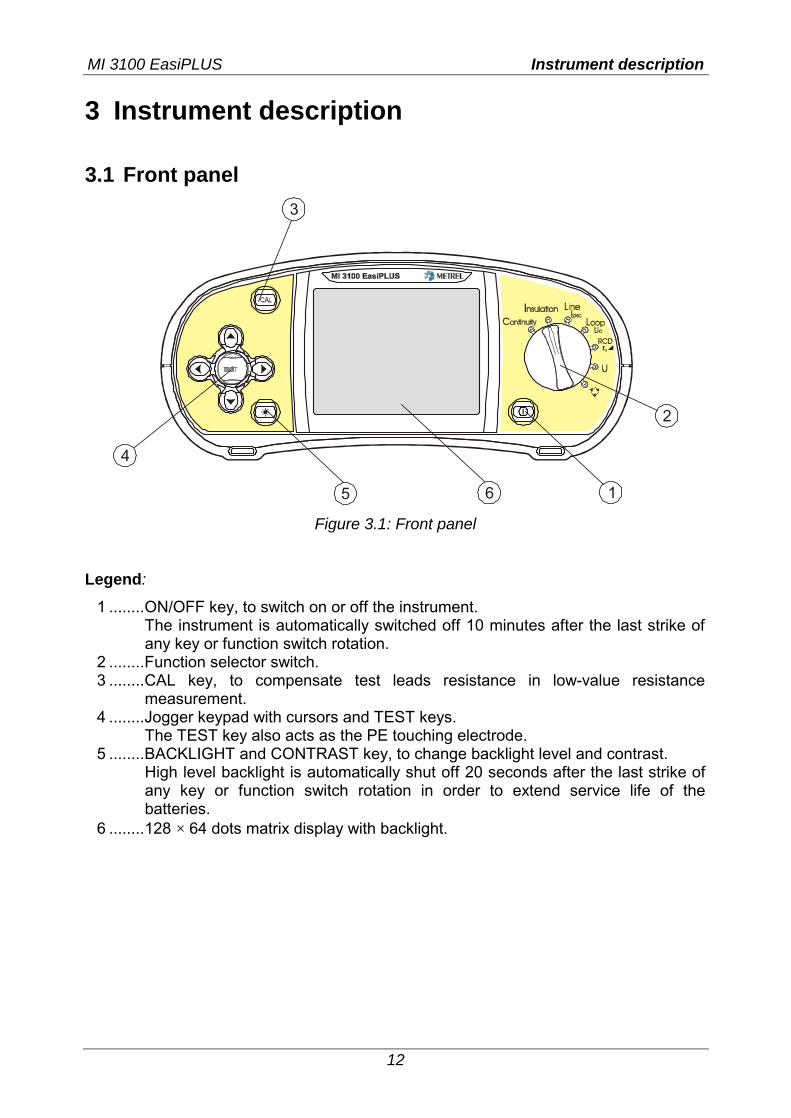
Figure 3.1: Front panel
Legend:
1 ........ON/OFF key, to switch on or off the instrument. The instrument is automatically switched off 10 minutes after the last strike of any key or function switch rotation.
2 ........Function selector switch. 3 ........CAL key, to compensate test leads resistance in low-value resistance
measurement. 4 ........Jogger keypad with cursors and TEST keys.
The TEST key also acts as the PE touching electrode. 5 ........BACKLIGHT and CONTRAST key, to change backlight level and contrast.
High level backlight is automatically shut off 20 seconds after the last strike of any key or function switch rotation in order to extend service life of the batteries.
6 ........128 × 64 dots matrix display with backlight.
MI 3100 EasiPLUS Instrument description
13
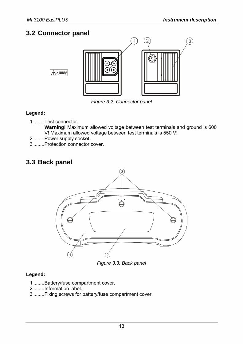
3.2 Connector panel 1 32
> 550V
Figure 3.2: Connector panel
Legend:
1 ........Test connector. Warning! Maximum allowed voltage between test terminals and ground is 600 V! Maximum allowed voltage between test terminals is 550 V!
2 ........Power supply socket. 3 ........Protection connector cover.
3.3 Back panel
1 2
3
Figure 3.3: Back panel
Legend:
1 ........Battery/fuse compartment cover. 2 ........Information label. 3 ........Fixing screws for battery/fuse compartment cover.
MI 3100 EasiPLUS Instrument description
14
564
12
3
F1F3F2FuseFuse
Fuse
SIZE AAS IZE AA SIZE AA
SIZE AASIZE AASIZE AA
S/N XXXXXXXX
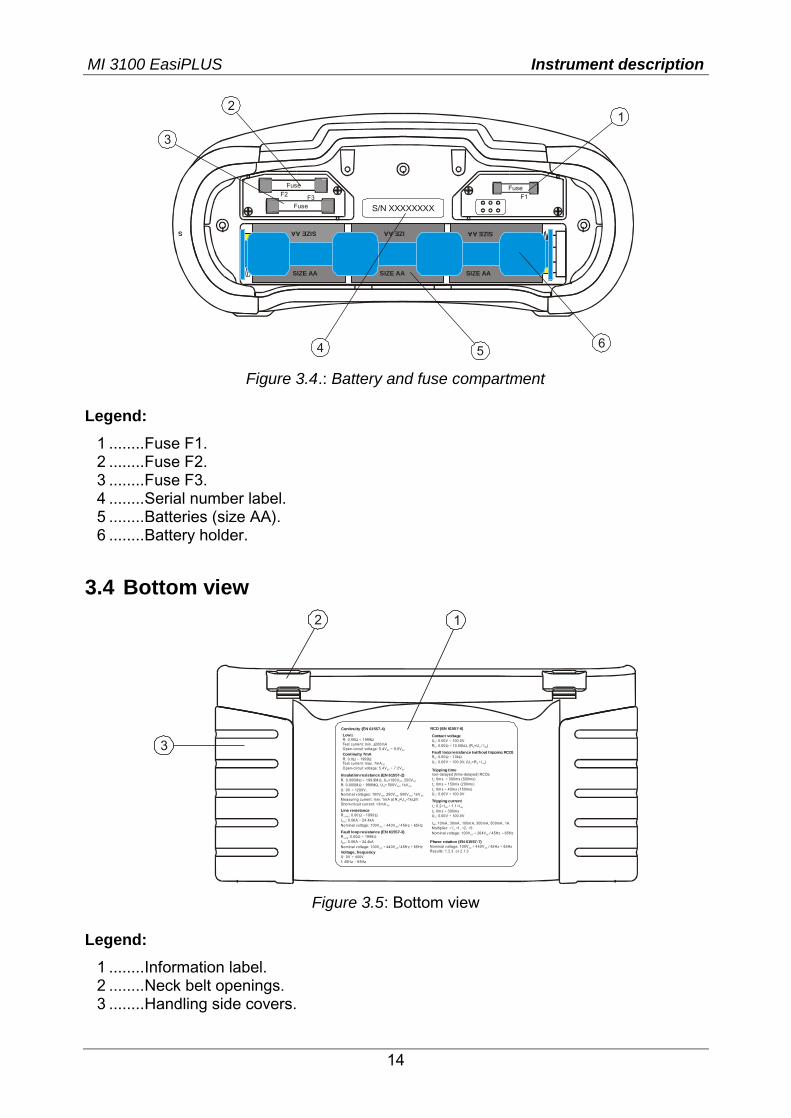
Figure 3.4.: Battery and fuse compartment
Legend:
1 ........Fuse F1. 2 ........Fuse F2. 3 ........Fuse F3. 4 ........Serial number label. 5 ........Batteries (size AA). 6 ........Battery holder.
3.4 Bottom view
Continuity 7mAR: 0.0 1999Test current: max . 7mAOpen-circuit voltage: 5.4V 7.2V
Ω ÷ Ω
÷ DC
DC DC
Insulation resistance (EN 61557-2)R: 0.000M 199.9M , U =100V , 250VR: 0.000M 999M , U = 500V , 1kVU: 0V 1200V,Nominal vol tages: 100V , 250V , 500V , 1kVMeasuring current: min. 1mA at R =U 1k /VShort-circuit current: <3mA
Ω ÷ ΩΩ ÷ Ω
÷
× Ω
N DC DC
N DC DC
DC DC DC DC
N N
DC
R: 0.00 1999Test current: min. ±200mAOpen-circuit voltage: 5.4V 9.0V
LowΩΩ ÷ Ω
÷ DC DC
Tripping timenon-delayed (time-delayed) RC Dst : 0ms 300ms (500ms)t : 0ms 150ms (200ms )t : 0ms 40ms (150ms)U : 0.00V 100.0V
∆
∆
∆
÷÷÷
÷ C
Tripping currentI : 0.2 I 1.1 It : 0ms 300msU : 0.00V 100.0V
∆ ∆ ∆
∆
× ÷ ×÷
÷
N N
C
Contact voltageU : 0.00V 100.0VR : 0.00 10.00k (R =U / I )
C
S S C N
÷Ω ÷ Ω, ∆
Fault loop resistance (without tripping RCD)R : 0.00 10kU : 0.00V 100.0V, (U =R I )
S
C C S N
Ω ÷ Ω÷ × ∆
Line resistanceR : 0.00 1999I : 0.06A 24.4kANominal vol tage: 100V 440V / 45H z 65Hz
L-N(L)
PSC
AC AC
Ω ÷ Ω÷
÷ ÷
Fault loop resistance (EN 61557-3)R : 0.00 1999I : 0.06A 24.4kANominal vol tage: 100V 440V / 45H z 65Hz
L-PE
PFC
AC AC
Ω ÷ Ω÷
÷ ÷ Voltage, frequencyU: 0V 440Vf: 45Hz 65Hz
÷÷
Phase rotation (EN 61557-7)Nominal v ol tage: 100V 440V / 45Hz 65Hz Results: 1.2.3. or 2.1.3
AC AC÷ ÷
I : 10mA, 30mA, 100mA, 300mA, 500mA, 1AMultiplier: / 1, 2, 5 Nominal v oltage: 100V 264V / 45Hz 65Hz
∆N
2
AC AC
× × × ×÷ ÷
1
RCD (EN 61557-6)Continuity (EN 61557-4)
3
12
Figure 3.5: Bottom view
Legend:
1 ........Information label. 2 ........Neck belt openings. 3 ........Handling side covers.
MI 3100 EasiPLUS Instrument description
15
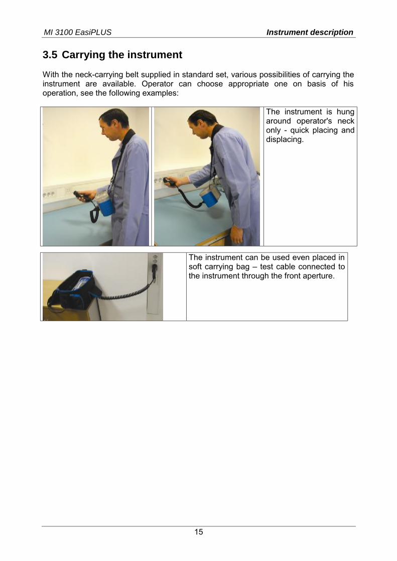
3.5 Carrying the instrument With the neck-carrying belt supplied in standard set, various possibilities of carrying the instrument are available. Operator can choose appropriate one on basis of his operation, see the following examples:
The instrument is hung around operator's neck only - quick placing and displacing.
The instrument can be used even placed in soft carrying bag – test cable connected to the instrument through the front aperture.
MI 3100 EasiPLUS Instrument description
16
3.6 Instrument set and accessories
Instrument EasiPLUS – MI 3100 Soft carying bag Soft carying neck belt Soft carying back belt
Measuring accessories*) Universal test cable (3 × 1.5 m) Mains measuring cable Test tip (blue) Test tip (black) Test tip (green) 3 aligator clips (black)
Documentation Short instruction manual Product verification data Warranty declaration Declaration of conformity
Battery 6 Ni-MH rechargeable battery cells Power supply adapter
CD-ROM Instruction manual Short instruction manual Measurement on electric installations in theory and practice
Optional accessories*)
Tip commander Three-phase cable Three-phase adapter Test lead (black, 4 m) Test lead (black, 20 m) Test lead (black, 50 m) Fast 12 cells charger (C and AA accu sizes) Fast 6 cells charger (AA accu size)
*) Please, see the attached sheet to compare received set of accessories with listed one. See also the attached sheet for a list of optional accessories that are available on request from your distributor.
MI 3100 EasiPLUS Instrument operation
17
4 Instrument operation
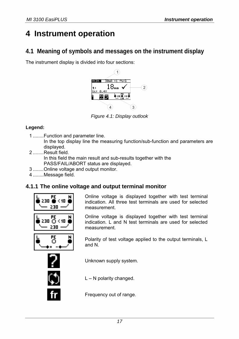
4.1 Meaning of symbols and messages on the instrument display The instrument display is divided into four sections:
1
2
34 Figure 4.1: Display outlook
Legend:
1 ........Function and parameter line. In the top display line the measuring function/sub-function and parameters are displayed.
2 ........Result field. In this field the main result and sub-results together with the PASS/FAIL/ABORT status are displayed.
3 ........Online voltage and output monitor. 4 ........Message field.
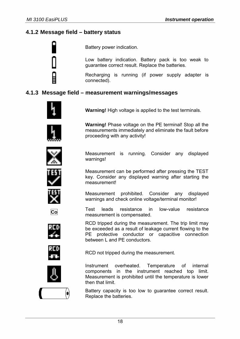
4.1.1 The online voltage and output terminal monitor
Online voltage is displayed together with test terminal indication. All three test terminals are used for selected measurement.
Online voltage is displayed together with test terminal indication. L and N test terminals are used for selected measurement.
Polarity of test voltage applied to the output terminals, L and N.
Unknown supply system.
L – N polarity changed.
fri Frequency out of range.
MI 3100 EasiPLUS Instrument operation
18
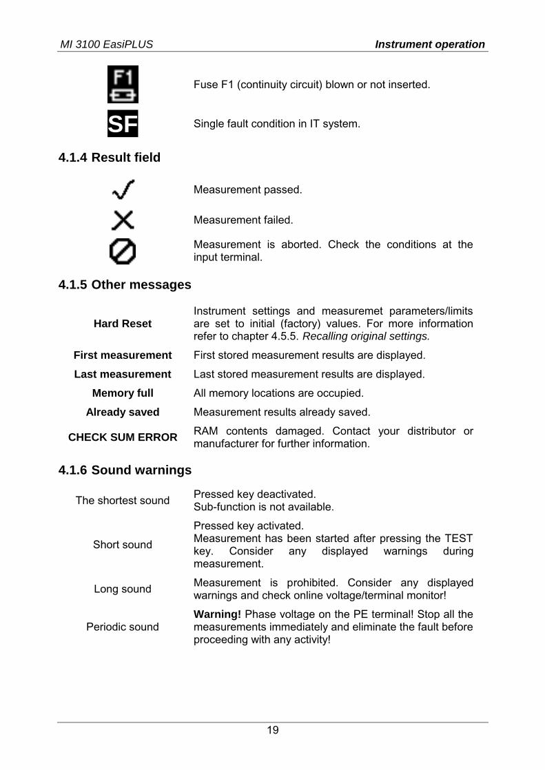
4.1.2 Message field – battery status
Battery power indication.
Low battery indication. Battery pack is too weak to guarantee correct result. Replace the batteries.
Recharging is running (if power supply adapter is connected).
4.1.3 Message field – measurement warnings/messages
Warning! High voltage is applied to the test terminals.
Warning! Phase voltage on the PE terminal! Stop all the measurements immediately and eliminate the fault before proceeding with any activity!
Measurement is running. Consider any displayed warnings!
Measurement can be performed after pressing the TEST key. Consider any displayed warning after starting the measurement!
Measurement prohibited. Consider any displayed warnings and check online voltage/terminal monitor!
Co Test leads resistance in low-value resistance measurement is compensated.
RCD tripped during the measurement. The trip limit may be exceeded as a result of leakage current flowing to the PE protective conductor or capacitive connection between L and PE conductors.
RCD not tripped during the measurement.
Instrument overheated. Temperature of internal components in the instrument reached top limit. Measurement is prohibited until the temperature is lower then that limit.
Battery capacity is too low to guarantee correct result. Replace the batteries.
MI 3100 EasiPLUS Instrument operation
19
Fuse F1 (continuity circuit) blown or not inserted.
SF Single fault condition in IT system.
4.1.4 Result field
Measurement passed.
Measurement failed.
Measurement is aborted. Check the conditions at the input terminal.
4.1.5 Other messages
Hard Reset Instrument settings and measuremet parameters/limits are set to initial (factory) values. For more information refer to chapter 4.5.5. Recalling original settings.
First measurement First stored measurement results are displayed.
Last measurement Last stored measurement results are displayed.
Memory full All memory locations are occupied.
Already saved Measurement results already saved.
CHECK SUM ERROR RAM contents damaged. Contact your distributor or manufacturer for further information.
4.1.6 Sound warnings
The shortest sound Pressed key deactivated. Sub-function is not available.
Short sound
Pressed key activated. Measurement has been started after pressing the TEST key. Consider any displayed warnings during measurement.
Long sound Measurement is prohibited. Consider any displayed warnings and check online voltage/terminal monitor!
Periodic sound Warning! Phase voltage on the PE terminal! Stop all the measurements immediately and eliminate the fault before proceeding with any activity!
MI 3100 EasiPLUS Instrument operation
20
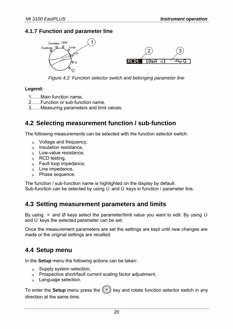
4.1.7 Function and parameter line
1
2 3
Figure 4.2: Function selector switch and belonging parameter line
Legend:
1……Main function name. 2……Function or sub-function name. 3……Measuring parameters and limit values.
4.2 Selecting measurement function / sub-function The following measurements can be selected with the function selector switch:
q Voltage and frequency, q Insulation resistance, q Low-value resistance, q RCD testing, q Fault loop impedance, q Line impedance, q Phase sequence.
The function / sub-function name is highlighted on the display by default. Sub-function can be selected by using Ù and Ú keys in function / parameter line.
4.3 Setting measurement parameters and limits By using × and Ø keys select the parameter/limit value you want to edit. By using Ù and Ú keys the selected parameter can be set.
Once the measurement parameters are set the settings are kept until new changes are made or the original settings are recalled.
4.4 Setup menu In the Setup menu the following actions can be taken:
q Supply system selection, q Prospective short/fault current scaling factor adjustment, q Language selection.
To enter the Setup menu press the key and rotate function selector switch in any direction at the same time.
MI 3100 EasiPLUS Instrument operation
21
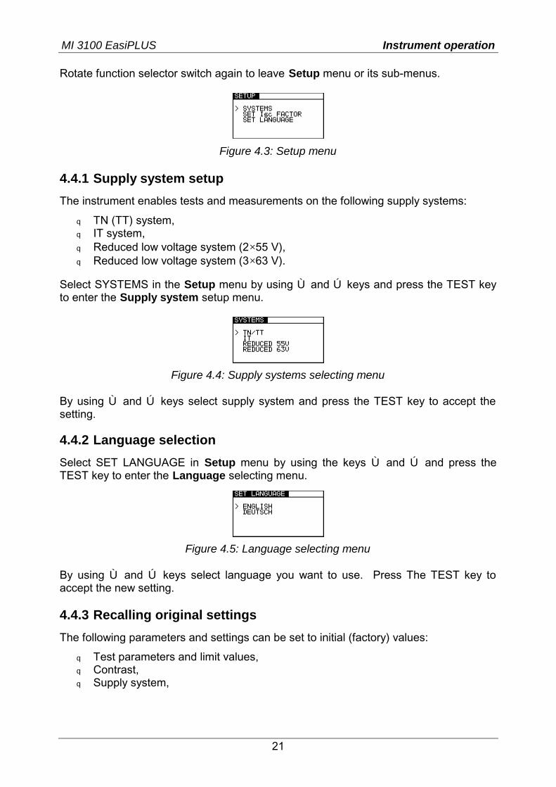
Rotate function selector switch again to leave Setup menu or its sub-menus.
Figure 4.3: Setup menu
4.4.1 Supply system setup
The instrument enables tests and measurements on the following supply systems:
q TN (TT) system, q IT system, q Reduced low voltage system (2×55 V), q Reduced low voltage system (3×63 V).
Select SYSTEMS in the Setup menu by using Ù and Ú keys and press the TEST key to enter the Supply system setup menu.
Figure 4.4: Supply systems selecting menu
By using Ù and Ú keys select supply system and press the TEST key to accept the setting. 4.4.2 Language selection Select SET LANGUAGE in Setup menu by using the keys Ù and Ú and press the TEST key to enter the Language selecting menu.
Figure 4.5: Language selecting menu
By using Ù and Ú keys select language you want to use. Press The TEST key to accept the new setting. 4.4.3 Recalling original settings
The following parameters and settings can be set to initial (factory) values:
q Test parameters and limit values, q Contrast, q Supply system,
MI 3100 EasiPLUS Instrument operation
22
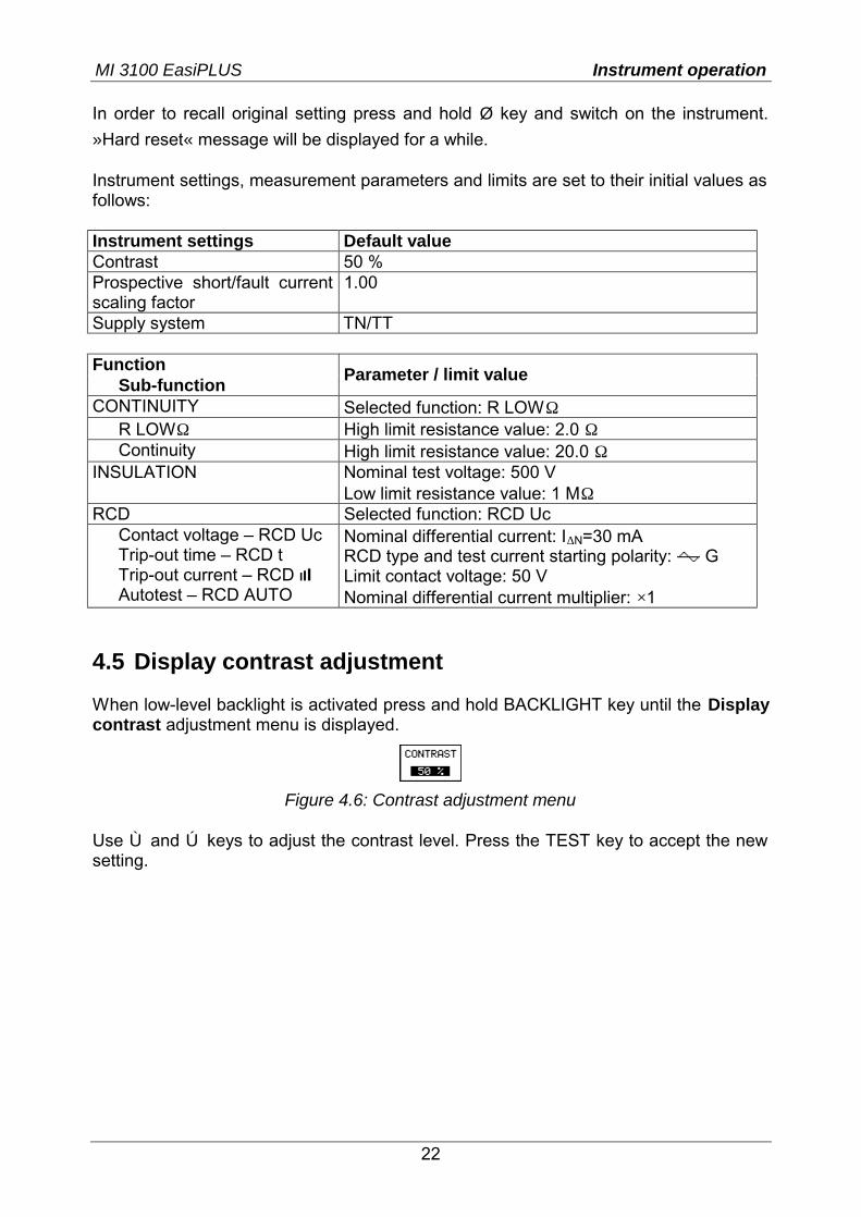
In order to recall original setting press and hold Ø key and switch on the instrument.
»Hard reset« message will be displayed for a while. Instrument settings, measurement parameters and limits are set to their initial values as follows: Instrument settings Default value Contrast 50 % Prospective short/fault current scaling factor
1.00
Supply system TN/TT Function
Sub-function Parameter / limit value
CONTINUITY Selected function: R LOWΩ R LOWΩ High limit resistance value: 2.0 Ω Continuity High limit resistance value: 20.0 Ω
INSULATION Nominal test voltage: 500 V Low limit resistance value: 1 MΩ
RCD Selected function: RCD Uc Contact voltage – RCD Uc Trip-out time – RCD t Trip-out current – RCD III Autotest – RCD AUTO
Nominal differential current: I∆N=30 mA RCD type and test current starting polarity: G Limit contact voltage: 50 V Nominal differential current multiplier: ×1
4.5 Display contrast adjustment When low-level backlight is activated press and hold BACKLIGHT key until the Display contrast adjustment menu is displayed.
Figure 4.6: Contrast adjustment menu
Use Ù and Ú keys to adjust the contrast level. Press the TEST key to accept the new setting.
MI 3100 EasiPLUS Measurements - Insulation resistance
23
5 Measurements
5.1 Insulation resistance Insulation resistance measurement is performed in order to assure safety against electric shock. Using this measurement the following items can be determined:
q Insulation resistance between installation conductors, q Insulation resistance of non-conductive rooms (walls and floors), q Insulation resistance of ground cables, q Resistance of semi-conductive (antistatic) floors.
For additional general information concerning insulation resistance measurement refer to the Metrel handbook Measurements on electric installations in theory and practice . How to perform insulation resistance measurement Step 1 Select Insulation function with the function selector switch. The following
menu is displayed:
Figure 5.1: Insulation resistance measurement menu
Connect test cable to the EasiPLUS instrument. Step 2 Set the following measuring parameter and limit values:
q Nominal test voltage, q Minimum insulation resistance.
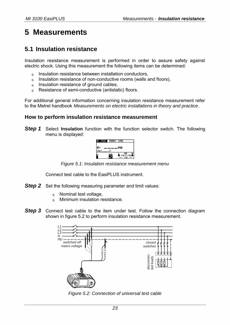
Step 3 Connect test cable to the item under test. Follow the connection diagram
shown in figure 5.2 to perform insulation resistance measurement.
L1L2L3NPE
switched offmains voltage
closed switches
disc
onne
c-te
d lo
ads
N/L
2
L/L1
PE
/L3
Figure 5.2: Connection of universal test cable
MI 3100 EasiPLUS Measurements - Insulation resistance
24
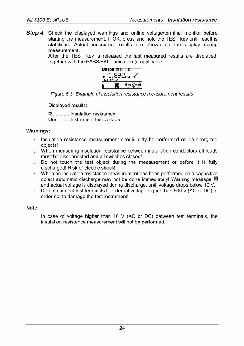
Step 4 Check the displayed warnings and online voltage/terminal monitor before starting the measurement. If OK, press and hold the TEST key until result is stabilised. Actual measured results are shown on the display during measurement. After the TEST key is released the last measured results are displayed, together with the PASS/FAIL indication (if applicable).
Figure 5.3: Example of insulation resistance measurement results
Displayed results:
R ............ Insulation resistance, Um ......... Instrument test voltage.
Warnings:
q Insulation resistance measurement should only be performed on de-energized objects!
q When measuring insulation resistance between installation conductors all loads must be disconnected and all switches closed!
q Do not touch the test object during the measurement or before it is fully discharged! Risk of electric shock!
q When an insulation resistance measurement has been performed on a capacitive object automatic discharge may not be done immediately! Warning message and actual voltage is displayed during discharge, until voltage drops below 10 V.
q Do not connect test terminals to external voltage higher than 600 V (AC or DC) in order not to damage the test instrument!
Note:
q In case of voltage higher than 10 V (AC or DC) between test terminals, the insulation resistance measurement will not be performed.
MI 3100 EasiPLUS Measurements - Continuty
25
5.2 Continuity Two Continuity sub-functions are available:
q LowΩ resistance, q Continuity.
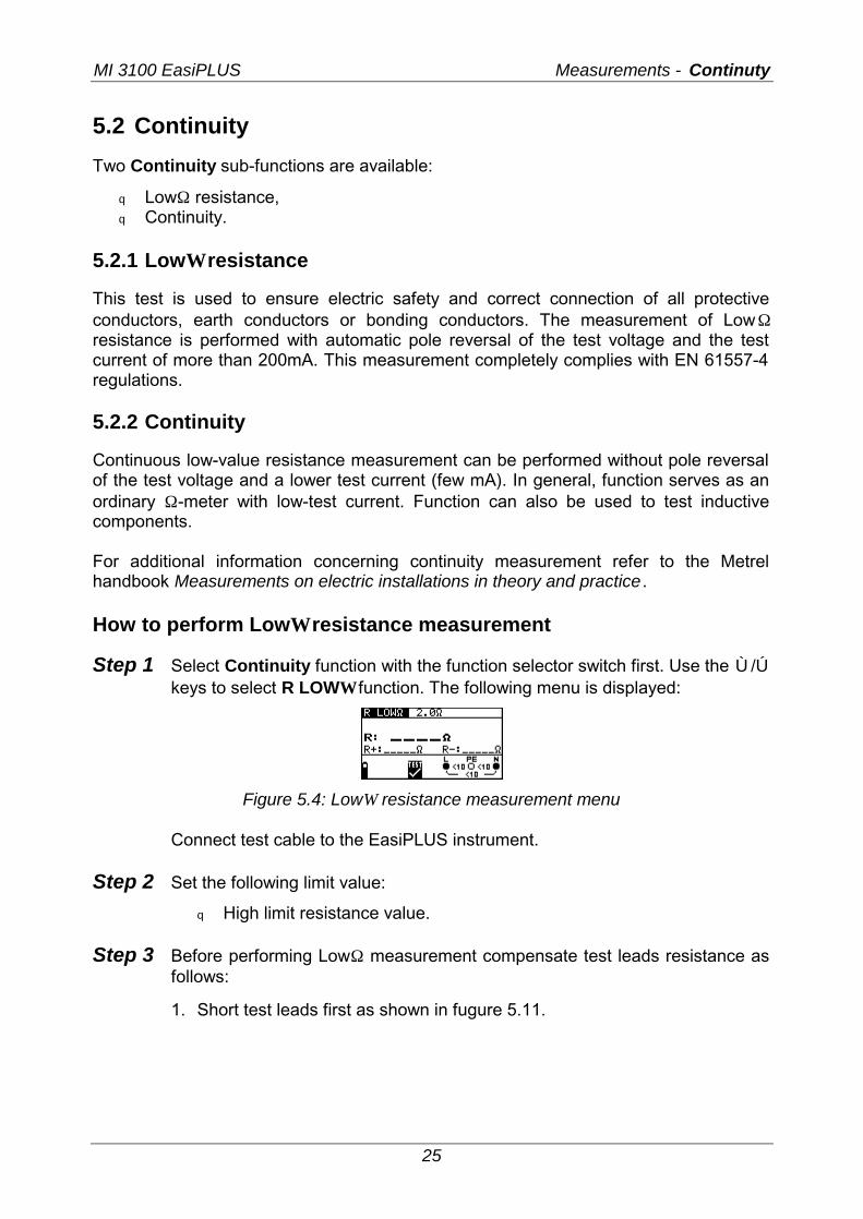
5.2.1 LowΩ resistance This test is used to ensure electric safety and correct connection of all protective conductors, earth conductors or bonding conductors. The measurement of LowΩ resistance is performed with automatic pole reversal of the test voltage and the test current of more than 200mA. This measurement completely complies with EN 61557-4 regulations. 5.2.2 Continuity Continuous low-value resistance measurement can be performed without pole reversal of the test voltage and a lower test current (few mA). In general, function serves as an ordinary Ω-meter with low-test current. Function can also be used to test inductive components. For additional information concerning continuity measurement refer to the Metrel handbook Measurements on electric installations in theory and practice . How to perform LowΩ resistance measurement Step 1 Select Continuity function with the function selector switch first. Use the Ù/Ú
keys to select R LOWΩ function. The following menu is displayed:
Figure 5.4: LowΩ resistance measurement menu
Connect test cable to the EasiPLUS instrument. Step 2 Set the following limit value:
q High limit resistance value. Step 3 Before performing LowΩ measurement compensate test leads resistance as
follows:
1. Short test leads first as shown in fugure 5.11.
MI 3100 EasiPLUS Measurements - Continuty
26
N/L2
L/L1 L/L1
PE/L3 N/L2PE/L3
extension lead
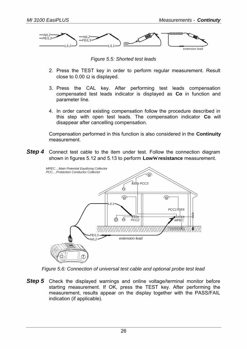
Figure 5.5: Shorted test leads
2. Press the TEST key in order to perform regular measurement. Result close to 0.00 Ω is displayed.
3. Press the CAL key. After performing test leads compensation
compensated test leads indicator is displayed as Co in function and parameter line.
4. In order cancel existing compensation follow the procedure described in
this step with open test leads. The compensation indicator Co will disappear after cancelling compensation.
Compensation performed in this function is also considered in the Continuity
measurement. Step 4 Connect test cable to the item under test. Follow the connection diagram
shown in figures 5.12 and 5.13 to perform LowΩ resistance measurement.
PCC1
PCC2
PCC3
N/L2PE/L3
L/L1
MPEC
MPEC....Main Potential Equilizing CollectorPCC....Protection Conductor Collector
extension lead
Figure 5.6: Connection of universal test cable and optional probe test lead
Step 5 Check the displayed warnings and online voltage/terminal monitor before starting measurement. If OK, press the TEST key. After performing the measurement, results appear on the display together with the PASS/FAIL indication (if applicable).
MI 3100 EasiPLUS Measurements - Continuty
27
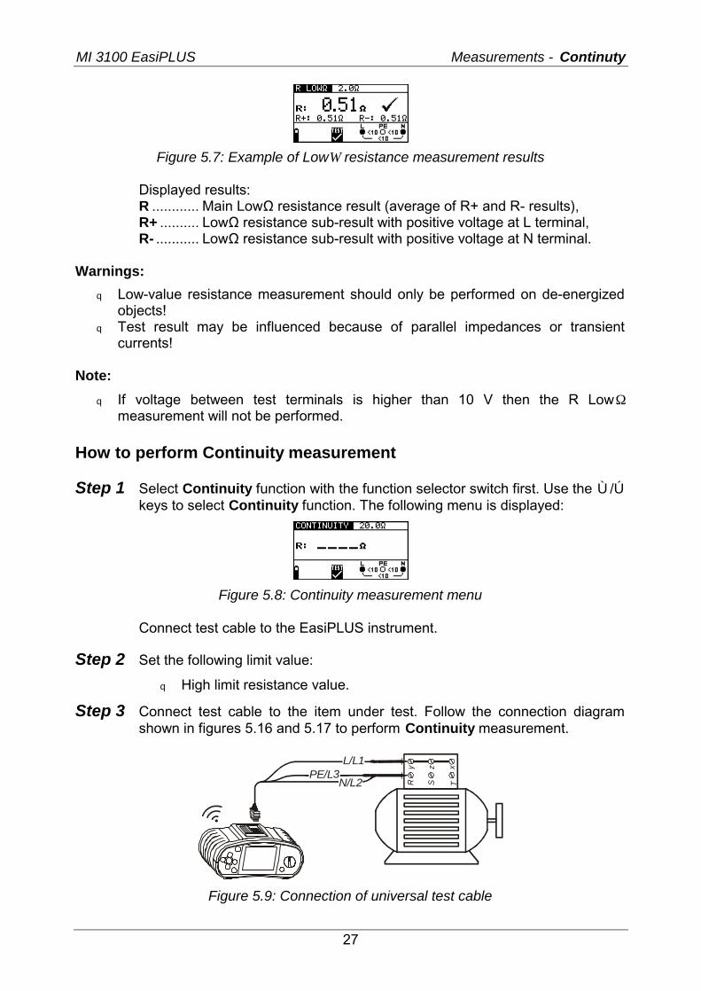
Figure 5.7: Example of LowΩ resistance measurement results
Displayed results: R ............ Main LowΩ resistance result (average of R+ and R- results), R+ .......... LowΩ resistance sub-result with positive voltage at L terminal, R- ........... LowΩ resistance sub-result with positive voltage at N terminal.
Warnings:
q Low-value resistance measurement should only be performed on de-energized objects!
q Test result may be influenced because of parallel impedances or transient currents!
Note:
q If voltage between test terminals is higher than 10 V then the R LowΩ measurement will not be performed.
How to perform Continuity measurement Step 1 Select Continuity function with the function selector switch first. Use the Ù/Ú
keys to select Continuity function. The following menu is displayed:
Figure 5.8: Continuity measurement menu
Connect test cable to the EasiPLUS instrument.
Step 2 Set the following limit value:
q High limit resistance value.
Step 3 Connect test cable to the item under test. Follow the connection diagram shown in figures 5.16 and 5.17 to perform Continuity measurement.
Ry
Sz
Tx
N/L2PE/L3
L/L1
Figure 5.9: Connection of universal test cable
MI 3100 EasiPLUS Measurements - Continuty
28
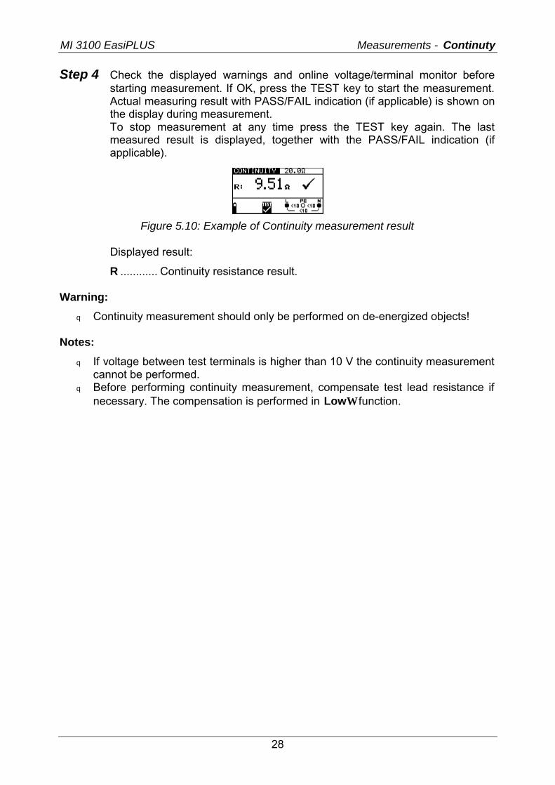
Step 4 Check the displayed warnings and online voltage/terminal monitor before starting measurement. If OK, press the TEST key to start the measurement. Actual measuring result with PASS/FAIL indication (if applicable) is shown on the display during measurement. To stop measurement at any time press the TEST key again. The last measured result is displayed, together with the PASS/FAIL indication (if applicable).
Figure 5.10: Example of Continuity measurement result
Displayed result:
R ............ Continuity resistance result. Warning:
q Continuity measurement should only be performed on de-energized objects! Notes:
q If voltage between test terminals is higher than 10 V the continuity measurement cannot be performed.
q Before performing continuity measurement, compensate test lead resistance if necessary. The compensation is performed in LowΩ function.
MI 3100 EasiPLUS Measurements - Fault loop impedance and PFC
29
5.3 Testing RCDs When testing RCDs, the following sub-functions can be performed:
q Contact voltage measurement, q Trip-out time measurement, q Trip-out current measurement, q RCD autotest.
In general, the following parameters and limits can be set when testing RCDs:
q Limit contact voltage, q Nominal differential RCD trip-out current, q Multiplier of nominal differential RCD trip-out current, q RCD type, q Test current starting polarity.
5.3.1 Limit contact voltage Safety contact voltage is limited to 50 VAC for standard domestic area. In special environments (hospitals, wet places, etc.) contact voltages up to 25 V AC are permitted. Limit contact voltage can be set in Contact voltage function only! 5.3.2 Nominal differential trip-out current Nominal residual current is the RCD rated trip-out current. The following RCD current ratings can be set: 10 mA, 30 mA, 100 mA, 300 mA, 500 mA and 1000 mA. 5.3.3 Multiplier of nominal residual current Selected nominal differential current can be multiplied by ½, 1, 2 or 5. 5.3.4 RCD type and test current starting polarity EasiPLUS instrument enables testing of general (non-delayed) and selective (time-delayed, marked with S symbol) RCDs, which are suited for:
q Alternating residual current (AC type, marked with symbol), q Pulsating DC residual current (A type, marked with symbol).
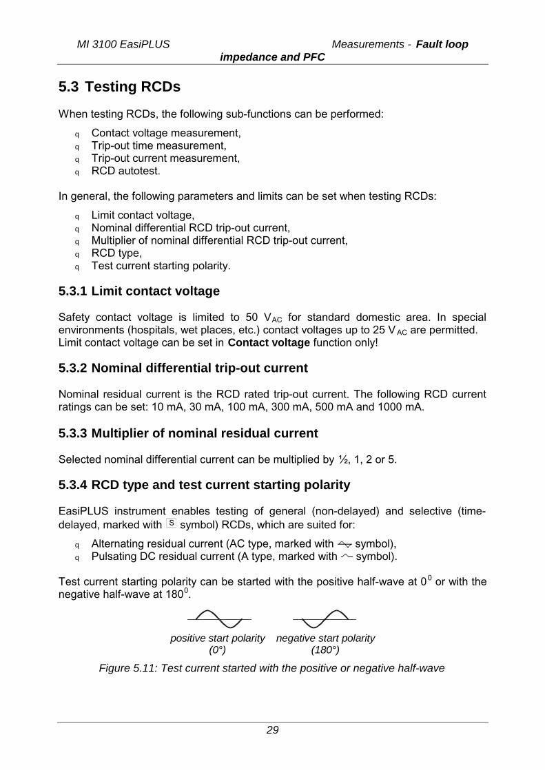
Test current starting polarity can be started with the positive half-wave at 00 or with the negative half-wave at 1800.
positive start polarity(0°)
negative start polarity(180°)
Figure 5.11: Test current started with the positive or negative half-wave
MI 3100 EasiPLUS Measurements - Testing RCDs
30
5.3.5 Testing selective (time-delayed) RCDs Selective RCDs demonstrate delayed response characteristics. Trip-out performance is influenced due to the pre-loading during measurement of contact voltage. In order to eliminate pre-loading a time delay of 30 s is inserted before performing trip-out test. 5.3.6 Contact voltage Leakage current flowing to the PE terminal causes a voltage drop across earth resistance, which is called contact voltage. This voltage is presented on all accessible parts connected to the PE terminal and should be lower than the safety limit voltage. The parameter contact voltage is measured without tripping-out the RCD. RL is a fault loop resistance and is calculated as follows:
N
CL I
UR∆
=
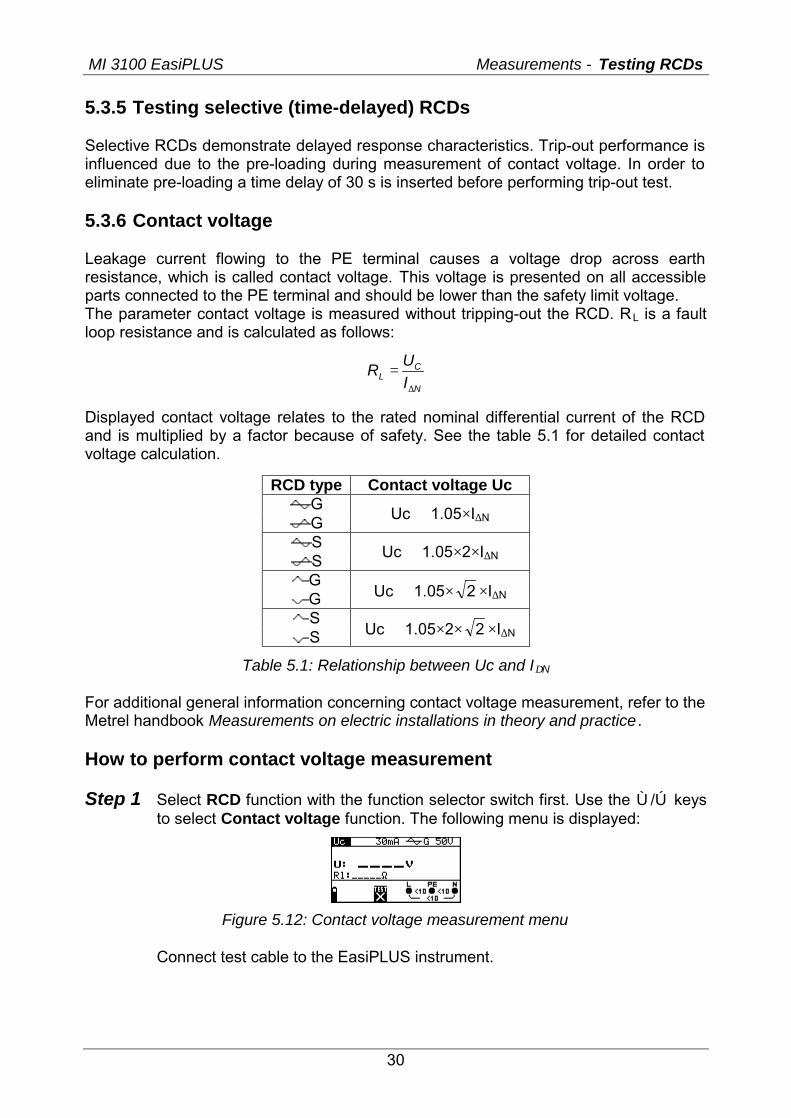
Displayed contact voltage relates to the rated nominal differential current of the RCD and is multiplied by a factor because of safety. See the table 5.1 for detailed contact voltage calculation.
RCD type Contact voltage Uc G G
Uc ∝ 1.05×I∆N
S S Uc ∝ 1.05×2×I∆N
G G Uc ∝ 1.05× 2 ×I∆N
S S Uc ∝ 1.05×2× 2 ×I∆N
Table 5.1: Relationship between Uc and I∆N
For additional general information concerning contact voltage measurement, refer to the Metrel handbook Measurements on electric installations in theory and practice . How to perform contact voltage measurement Step 1 Select RCD function with the function selector switch first. Use the Ù/Ú keys
to select Contact voltage function. The following menu is displayed:
Figure 5.12: Contact voltage measurement menu
Connect test cable to the EasiPLUS instrument.
MI 3100 EasiPLUS Measurements - Testing RCDs
31
Step 2 Set the following measuring parameters and limit values:
q Nominal residual current, q RCD type, q Limit contact voltage.
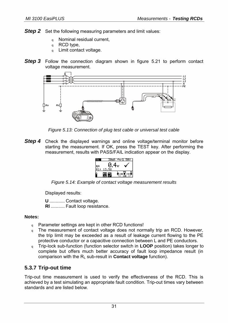
Step 3 Follow the connection diagram shown in figure 5.21 to perform contact
voltage measurement.
L1L2L3NPE
RERo
LPEN
L/L1N/L2
PE/L3
Figure 5.13: Connection of plug test cable or universal test cable
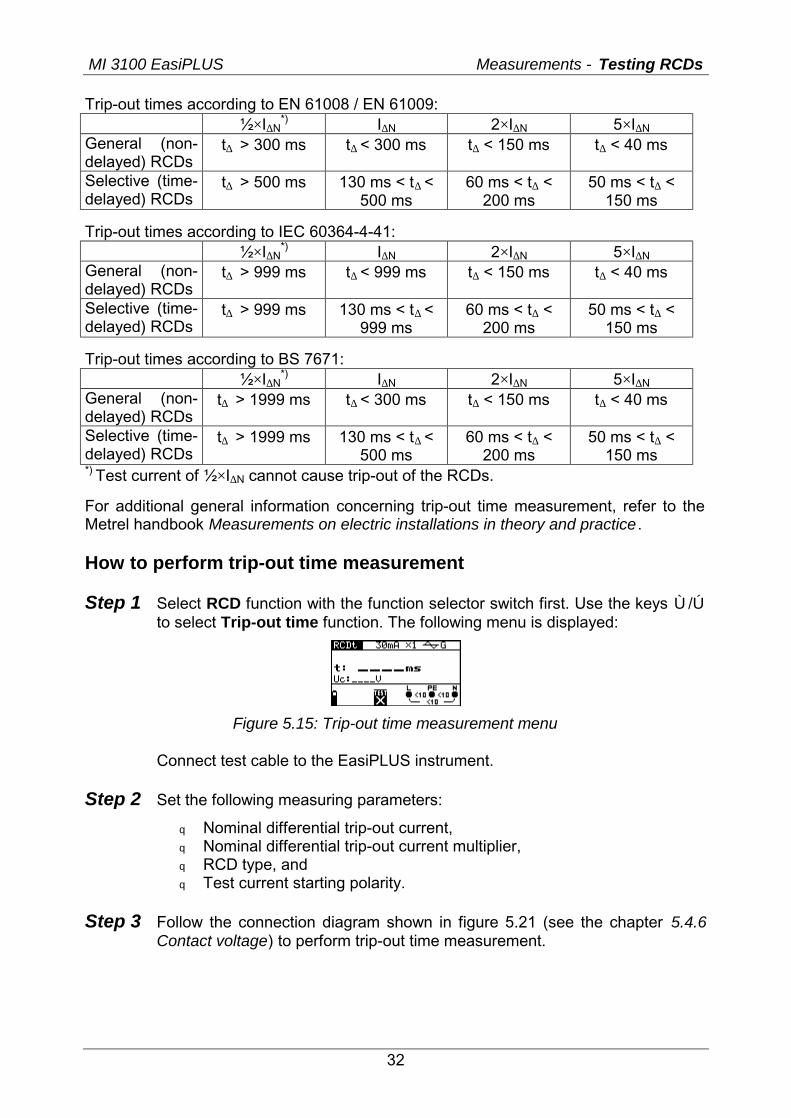
Step 4 Check the displayed warnings and online voltage/terminal monitor before starting the measurement. If OK, press the TEST key. After performing the measurement, results with PASS/FAIL indication appear on the display.
Figure 5.14: Example of contact voltage measurement results
Displayed results:
U ............ Contact voltage. Rl ........... Fault loop resistance.
Notes:
q Parameter settings are kept in other RCD functions! q The measurement of contact voltage does not normally trip an RCD. However,
the trip limit may be exceeded as a result of leakage current flowing to the PE protective conductor or a capacitive connection between L and PE conductors.
q Trip-lock sub-function (function selector switch in LOOP position) takes longer to complete but offers much better accuracy of fault loop impedance result (in comparison with the RL sub-result in Contact voltage function).
5.3.7 Trip-out time
Trip-out time measurement is used to verify the effectiveness of the RCD. This is achieved by a test simulating an appropriate fault condition. Trip-out times vary between standards and are listed below.
MI 3100 EasiPLUS Measurements - Testing RCDs
32
Trip-out times according to EN 61008 / EN 61009: ½×I∆N
*) I∆N 2×I∆N 5×I∆N General (non-delayed) RCDs
t∆ > 300 ms t∆ < 300 ms t∆ < 150 ms t∆ < 40 ms
Selective (time-delayed) RCDs
t∆ > 500 ms 130 ms < t∆ < 500 ms
60 ms < t∆ < 200 ms
50 ms < t∆ < 150 ms
Trip-out times according to IEC 60364-4-41: ½×I∆N
*) I∆N 2×I∆N 5×I∆N General (non-delayed) RCDs
t∆ > 999 ms t∆ < 999 ms t∆ < 150 ms t∆ < 40 ms
Selective (time-delayed) RCDs
t∆ > 999 ms 130 ms < t∆ < 999 ms
60 ms < t∆ < 200 ms
50 ms < t∆ < 150 ms
Trip-out times according to BS 7671: ½×I∆N
*) I∆N 2×I∆N 5×I∆N General (non-delayed) RCDs
t∆ > 1999 ms t∆ < 300 ms t∆ < 150 ms t∆ < 40 ms
Selective (time-delayed) RCDs
t∆ > 1999 ms 130 ms < t∆ < 500 ms
60 ms < t∆ < 200 ms
50 ms < t∆ < 150 ms
*) Test current of ½×I∆N cannot cause trip-out of the RCDs.
For additional general information concerning trip-out time measurement, refer to the Metrel handbook Measurements on electric installations in theory and practice . How to perform trip-out time measurement Step 1 Select RCD function with the function selector switch first. Use the keys Ù/Ú
to select Trip-out time function. The following menu is displayed:
Figure 5.15: Trip-out time measurement menu
Connect test cable to the EasiPLUS instrument.
Step 2 Set the following measuring parameters:
q Nominal differential trip-out current, q Nominal differential trip-out current multiplier, q RCD type, and q Test current starting polarity.
Step 3 Follow the connection diagram shown in figure 5.21 (see the chapter 5.4.6
Contact voltage) to perform trip-out time measurement.
MI 3100 EasiPLUS Measurements - Testing RCDs
33
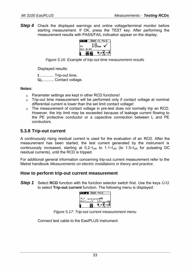
Step 4 Check the displayed warnings and online voltage/terminal monitor before starting measurement. If OK, press the TEST key. After performing the measurement results with PASS/FAIL indication appear on the display.
Figure 5.16: Example of trip-out time measurement results
Displayed results:
t.............. Trip-out time, UC........... Contact voltage.
Notes:
q Parameter settings are kept in other RCD functions! q Trip-out time measurement will be performed only if contact voltage at nominal
differential current is lower than the set limit contact voltage! q The measurement of contact voltage in pre-test does not normally trip an RCD.
However, the trip limit may be exceeded because of leakage current flowing to the PE protective conductor or a capacitive connection between L and PE conductors.
5.3.8 Trip-out current
A continuously rising residual current is used for the evaluation of an RCD. After the measurement has been started, the test current generated by the instrument is continuously increased, starting at 0.2×I∆N to 1.1×I∆N (to 1.5×I∆N for pulsating DC residual currents), until the RCD is tripped.
For additional general information concerning trip-out current measurement refer to the Metrel handbook Measurements on electric installations in theory and practice . How to perform trip-out current measurement Step 1 Select RCD function with the function selector switch first. Use the keys Ù/Ú
to select Trip-out current function. The following menu is displayed:
Figure 5.17: Trip-out current measurement menu
Connect test cable to the EasiPLUS instrument.
MI 3100 EasiPLUS Measurements - Testing RCDs
34
Step 2 By using cursor keys the following parameters can be set in this measurement:
q Nominal residual current, q RCD type, q Test current starting polarity.
Step 3 Follow the connection diagram shown in figure 5.21 (see the chapter 5.4.6 Contact voltage) to perform trip-out current measurement.
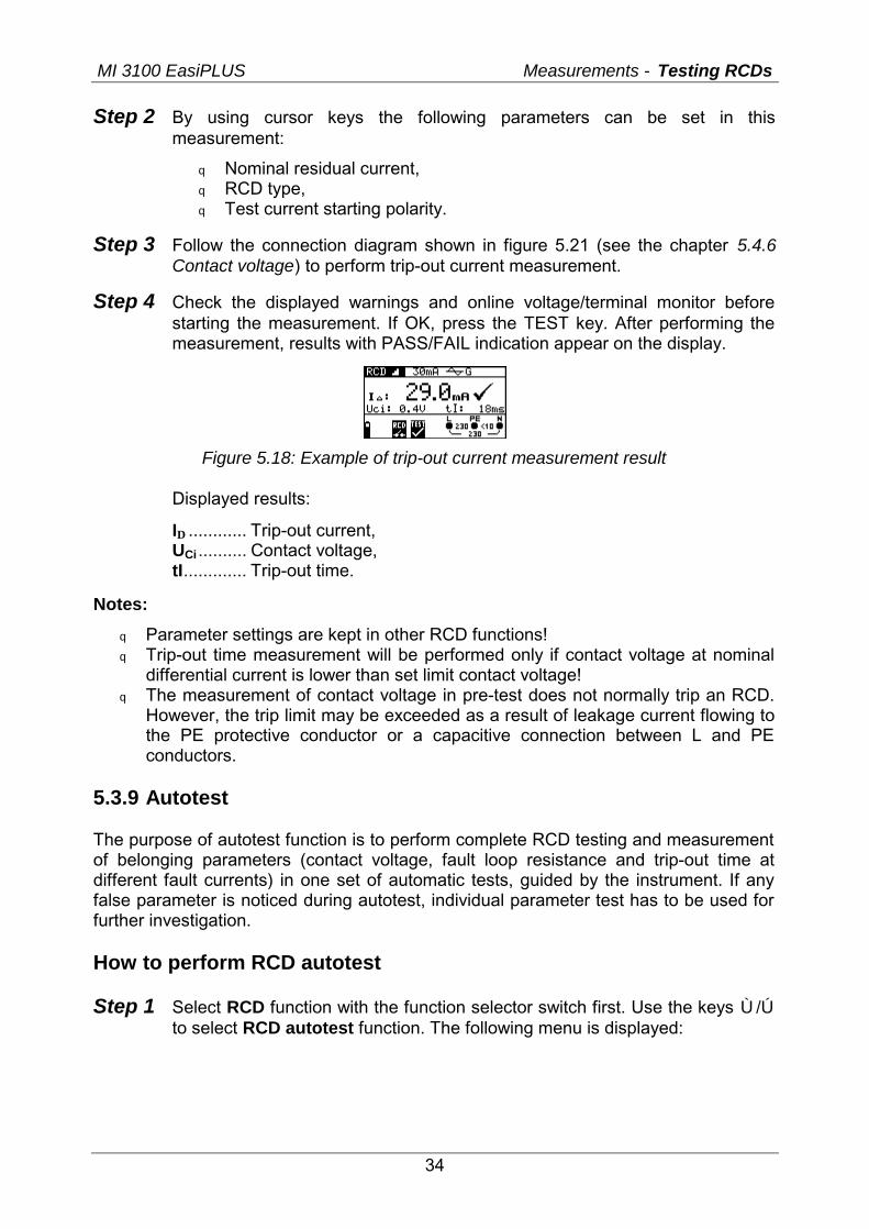
Step 4 Check the displayed warnings and online voltage/terminal monitor before starting the measurement. If OK, press the TEST key. After performing the measurement, results with PASS/FAIL indication appear on the display.
Figure 5.18: Example of trip-out current measurement result
Displayed results:
I∆ ............ Trip-out current, UCi .......... Contact voltage, tI............. Trip-out time.
Notes:
q Parameter settings are kept in other RCD functions! q Trip-out time measurement will be performed only if contact voltage at nominal
differential current is lower than set limit contact voltage! q The measurement of contact voltage in pre-test does not normally trip an RCD.
However, the trip limit may be exceeded as a result of leakage current flowing to the PE protective conductor or a capacitive connection between L and PE conductors.
5.3.9 Autotest The purpose of autotest function is to perform complete RCD testing and measurement of belonging parameters (contact voltage, fault loop resistance and trip-out time at different fault currents) in one set of automatic tests, guided by the instrument. If any false parameter is noticed during autotest, individual parameter test has to be used for further investigation. How to perform RCD autotest Step 1 Select RCD function with the function selector switch first. Use the keys Ù/Ú
to select RCD autotest function. The following menu is displayed:
MI 3100 EasiPLUS Measurements - Testing RCDs
35
Figure 5.19: RCD autotest menu
Connect test cable to the EasiPLUS instrument.
Step 2 Set the following measuring parameters:
q Nominal differential trip-out current, q RCD type.
Step 3 Follow the connection diagram shown in figure 5.21 (see the chapter 5.4.6 Contact voltage) to perform the RCD auto test.
Step 4 Check the displayed warnings and online voltage/terminal monitor before starting the measurement. If OK, press the TEST key. The auto test sequence starts to run as follows:
1. Trip-out time measurement with the following measurement parameters:
q Test current of ½×I∆N, q Test current started with the positive half-wave at 0º.
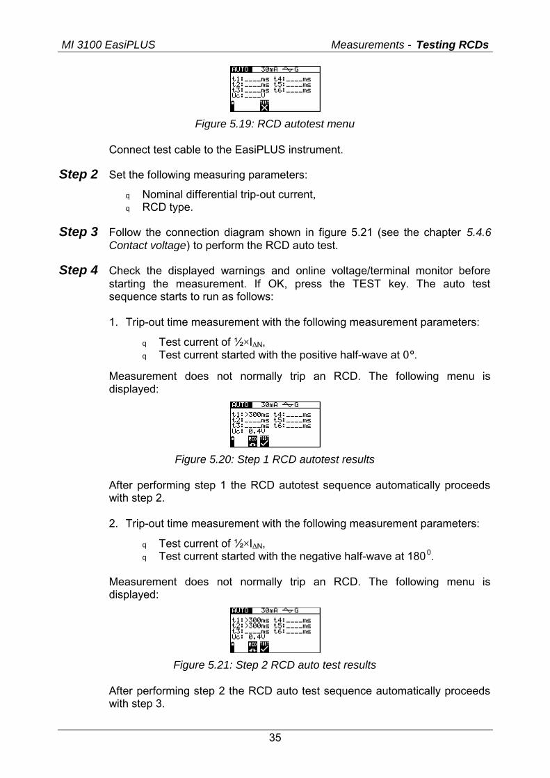
Measurement does not normally trip an RCD. The following menu is displayed:
Figure 5.20: Step 1 RCD autotest results
After performing step 1 the RCD autotest sequence automatically proceeds with step 2.
2. Trip-out time measurement with the following measurement parameters:
q Test current of ½×I∆N, q Test current started with the negative half-wave at 1800.
Measurement does not normally trip an RCD. The following menu is displayed:
Figure 5.21: Step 2 RCD auto test results
After performing step 2 the RCD auto test sequence automatically proceeds with step 3.
MI 3100 EasiPLUS Measurements - Testing RCDs
36
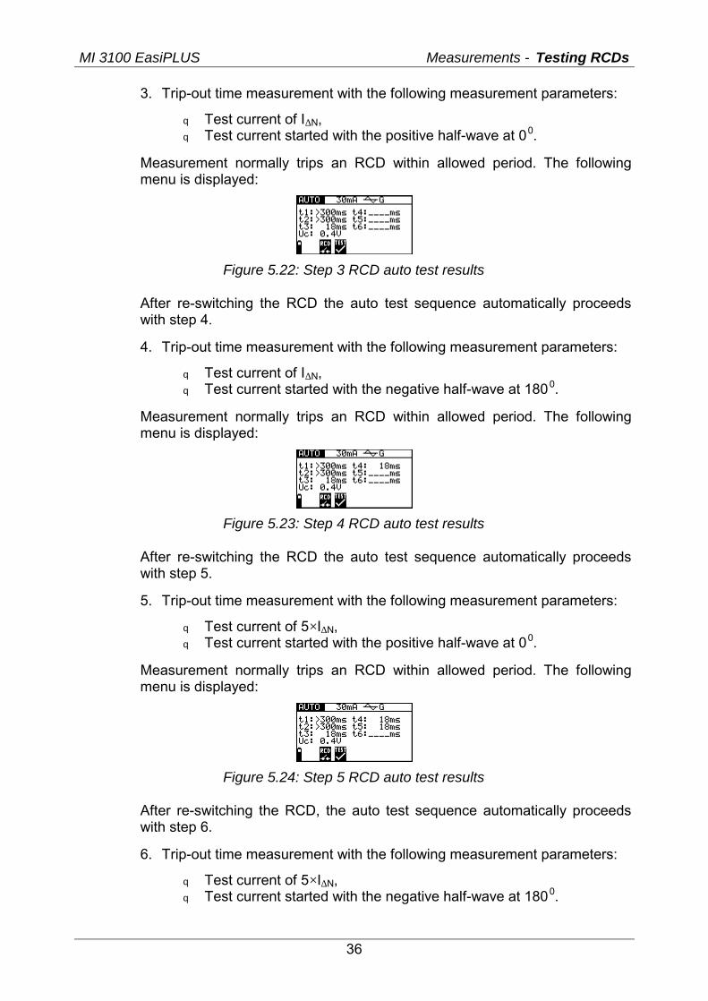
3. Trip-out time measurement with the following measurement parameters:
q Test current of I∆N, q Test current started with the positive half-wave at 00.
Measurement normally trips an RCD within allowed period. The following menu is displayed:
Figure 5.22: Step 3 RCD auto test results
After re-switching the RCD the auto test sequence automatically proceeds with step 4.
4. Trip-out time measurement with the following measurement parameters:
q Test current of I∆N, q Test current started with the negative half-wave at 1800.
Measurement normally trips an RCD within allowed period. The following menu is displayed:
Figure 5.23: Step 4 RCD auto test results
After re-switching the RCD the auto test sequence automatically proceeds with step 5.
5. Trip-out time measurement with the following measurement parameters:
q Test current of 5×I∆N, q Test current started with the positive half-wave at 00.
Measurement normally trips an RCD within allowed period. The following menu is displayed:
Figure 5.24: Step 5 RCD auto test results
After re-switching the RCD, the auto test sequence automatically proceeds with step 6.
6. Trip-out time measurement with the following measurement parameters:
q Test current of 5×I∆N, q Test current started with the negative half-wave at 1800.
MI 3100 EasiPLUS Measurements - Testing RCDs
37
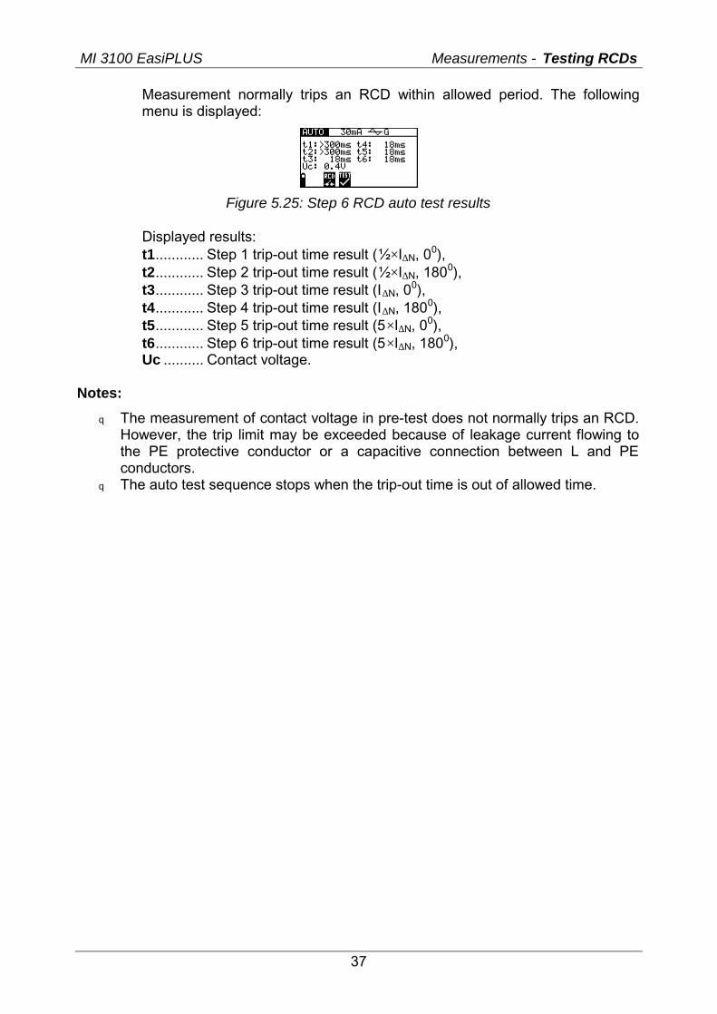
Measurement normally trips an RCD within allowed period. The following menu is displayed:
Figure 5.25: Step 6 RCD auto test results
Displayed results: t1............ Step 1 trip-out time result (½×I∆N, 00), t2............ Step 2 trip-out time result (½×I∆N, 1800), t3............ Step 3 trip-out time result (I∆N, 00), t4............ Step 4 trip-out time result (I∆N, 1800), t5............ Step 5 trip-out time result (5×I∆N, 00), t6............ Step 6 trip-out time result (5×I∆N, 1800), Uc .......... Contact voltage.
Notes:
q The measurement of contact voltage in pre-test does not normally trips an RCD. However, the trip limit may be exceeded because of leakage current flowing to the PE protective conductor or a capacitive connection between L and PE conductors.
q The auto test sequence stops when the trip-out time is out of allowed time.
MI 3100 EasiPLUS Measurements - Fault loop impedance and PFC
38
5.4 Fault loop impedance and prospective fault current Three LOOP sub-functions are available:
q Z LOOP sub-function performs fault loop impedance measurement in supply systems without RCDs,
q Z LOOP(rcd) trip-lock sub-function performs fault loop impedance measurement in supply systems equipped with an RCD.
5.4.1 Fault loop impedance Loop impedance is the impedance within the fault loop when short-circuit to an exposed conductive parts occurs (conductive connection between phase conductor and protective earth conductor). In order to measure loop impedance the instrument uses test current of 2.5 A. Prospective fault current is calculated on basis of measured impedance as follows:
PEL
NPFC Z
factorscalingUI−
×=
where
Un 115 V (100 V ≤ UL-PE < 160 V), 230 V (160 V ≤ UL-PE ≤ 264 V).
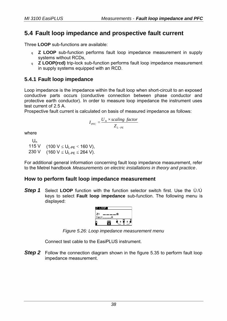
For additional general information concerning fault loop impedance measurement, refer to the Metrel handbook Measurements on electric installations in theory and practice . How to perform fault loop impedance measurement Step 1 Select LOOP function with the function selector switch first. Use the Ù/Ú
keys to select Fault loop impedance sub-function. The following menu is displayed:
Figure 5.26: Loop impedance measurement menu
Connect test cable to the EasiPLUS instrument.
Step 2 Follow the connection diagram shown in the figure 5.35 to perform fault loop impedance measurement.
MI 3100 EasiPLUS Measurements - Fault loop impedance and PFC
39
L1L2L3N
PE
RERo
LPEN
L/L1N/L2
PE/L3
Figure 5.27: Connection of plug cable and universal test cable
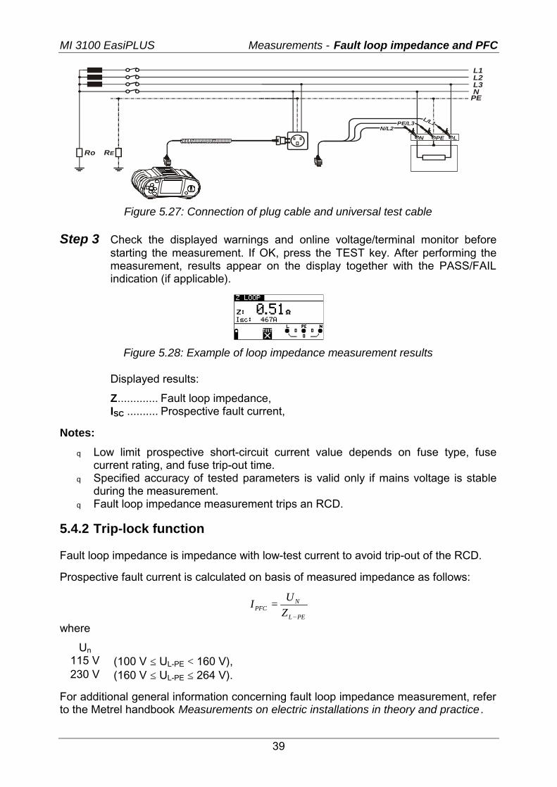
Step 3 Check the displayed warnings and online voltage/terminal monitor before starting the measurement. If OK, press the TEST key. After performing the measurement, results appear on the display together with the PASS/FAIL indication (if applicable).
Figure 5.28: Example of loop impedance measurement results
Displayed results:
Z............. Fault loop impedance, ISC .......... Prospective fault current,
Notes:
q Low limit prospective short-circuit current value depends on fuse type, fuse current rating, and fuse trip-out time.
q Specified accuracy of tested parameters is valid only if mains voltage is stable during the measurement.
q Fault loop impedance measurement trips an RCD.
5.4.2 Trip-lock function Fault loop impedance is impedance with low-test current to avoid trip-out of the RCD.
Prospective fault current is calculated on basis of measured impedance as follows:
PEL
NPFC Z
UI−
=
where
Un 115 V (100 V ≤ UL-PE < 160 V), 230 V (160 V ≤ UL-PE ≤ 264 V).
For additional general information concerning fault loop impedance measurement, refer to the Metrel handbook Measurements on electric installations in theory and practice .
MI 3100 EasiPLUS Measurements - Fault loop impedance and PFC
40
How to perform RCD trip-lock measurement Step 1 Select LOOP function with the function selector switch. The following menus
is displayed:
Figure 5.29: Trip-lock function menus Connect test cable to the EasiPLUS instrument.
Step 2 Follow the connection diagram shown in figure 5.21 to perform RCD trip-lock measurement (see chapter 5.4.6 Contact voltage).
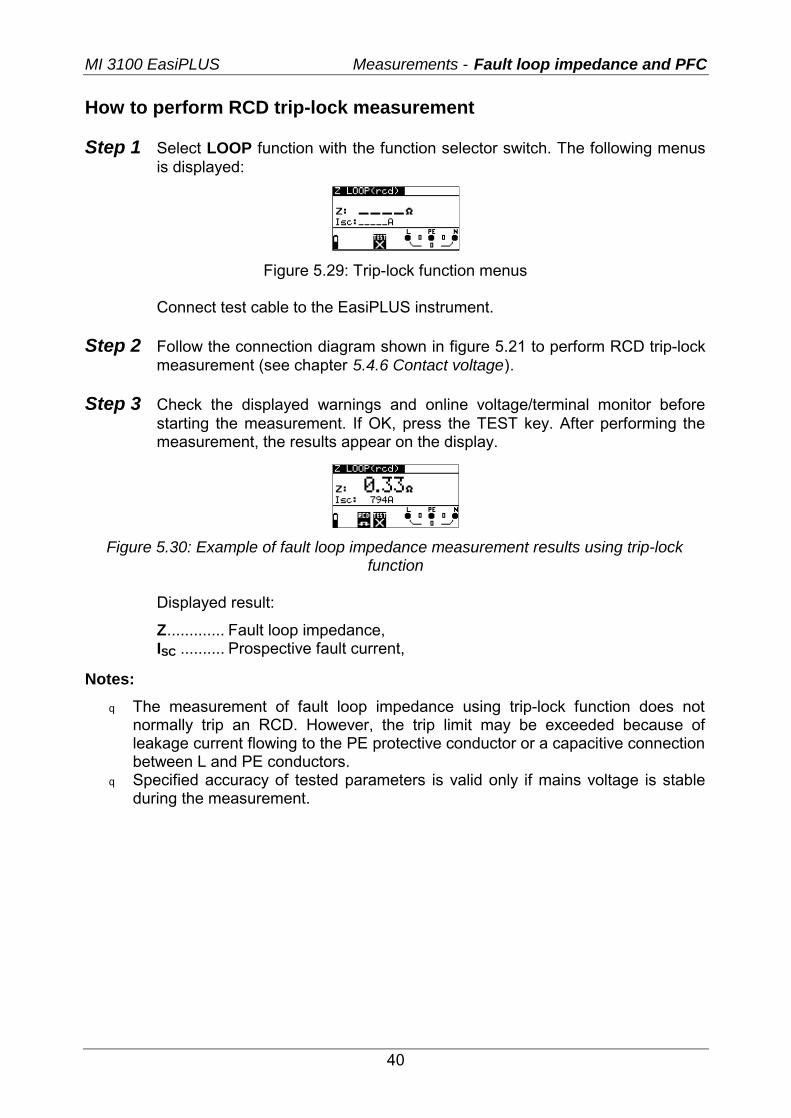
Step 3 Check the displayed warnings and online voltage/terminal monitor before
starting the measurement. If OK, press the TEST key. After performing the measurement, the results appear on the display.
Figure 5.30: Example of fault loop impedance measurement results using trip-lock
function
Displayed result:
Z............. Fault loop impedance, ISC .......... Prospective fault current,
Notes:
q The measurement of fault loop impedance using trip-lock function does not normally trip an RCD. However, the trip limit may be exceeded because of leakage current flowing to the PE protective conductor or a capacitive connection between L and PE conductors.
q Specified accuracy of tested parameters is valid only if mains voltage is stable during the measurement.
MI 3100 EasiPLUS Measurements - Line impedance and PFC
41
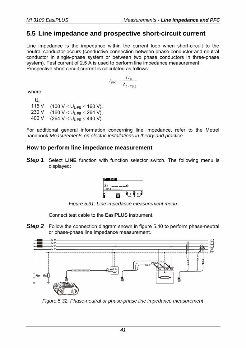
5.5 Line impedance and prospective short-circuit current Line impedance is the impedance within the current loop when short-circuit to the neutral conductor occurs (conductive connection between phase conductor and neutral conductor in single-phase system or between two phase conductors in three-phase system). Test current of 2.5 A is used to perform line impedance measurement. Prospective short circuit current is calculated as follows:
)(LNL
NPSC Z
UI−
=
where
Un 115 V (100 V ≤ UL-PE < 160 V), 230 V (160 V ≤ UL-PE ≤ 264 V), 400 V (264 V < UL-PE ≤ 440 V).
For additional general information concerning line impedance, refer to the Metrel handbook Measurements on electric installations in theory and practice . How to perform line impedance measurement Step 1 Select LINE function with function selector switch. The following menu is
displayed:
Figure 5.31: Line impedance measurement menu
Connect test cable to the EasiPLUS instrument.
Step 2 Follow the connection diagram shown in figure 5.40 to perform phase-neutral or phase-phase line impedance measurement.
L1L2L3N
PE
RERo
LPEN
L/L1N/L2
PE/L3
N/L
2
L/L1
PE/L
3
Figure 5.32: Phase-neutral or phase-phase line impedance measurement
MI 3100 EasiPLUS Measurements - Line impedance and PFC
42
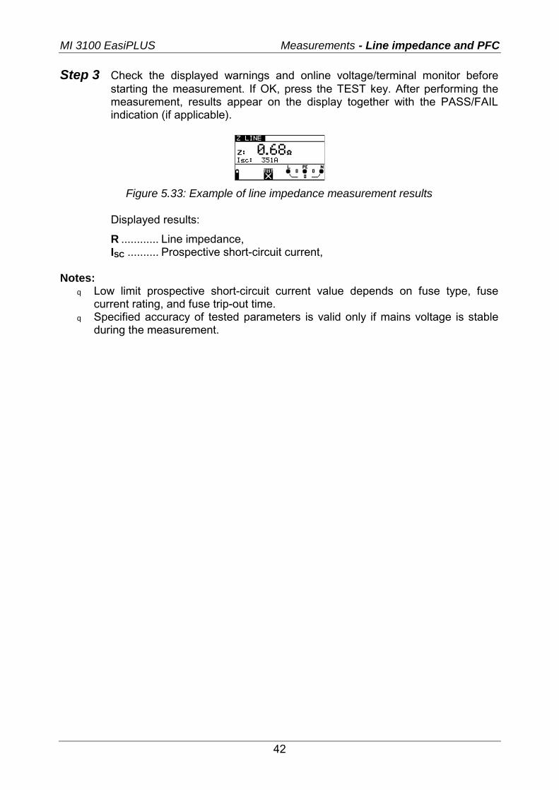
Step 3 Check the displayed warnings and online voltage/terminal monitor before starting the measurement. If OK, press the TEST key. After performing the measurement, results appear on the display together with the PASS/FAIL indication (if applicable).
Figure 5.33: Example of line impedance measurement results
Displayed results:
R ............ Line impedance, ISC .......... Prospective short-circuit current,
Notes:
q Low limit prospective short-circuit current value depends on fuse type, fuse current rating, and fuse trip-out time.
q Specified accuracy of tested parameters is valid only if mains voltage is stable during the measurement.
MI 3100 EasiPLUS Measurements - Phase sequence testing
43
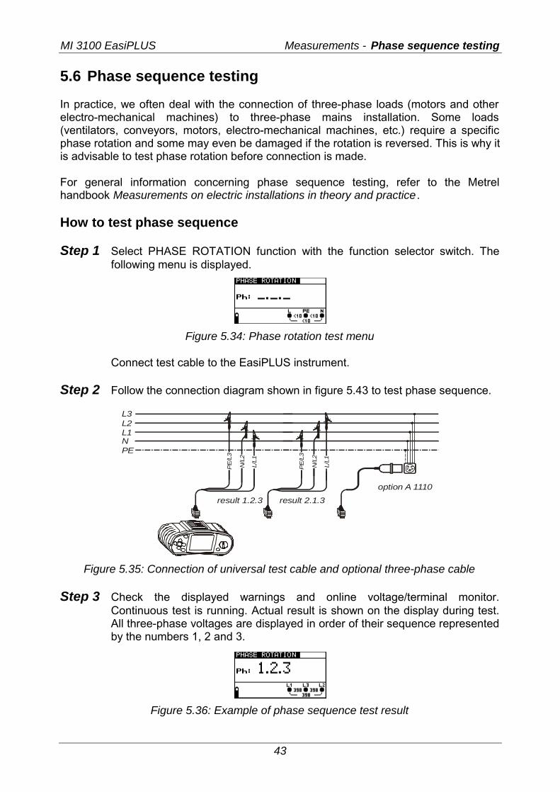
5.6 Phase sequence testing In practice, we often deal with the connection of three-phase loads (motors and other electro-mechanical machines) to three-phase mains installation. Some loads (ventilators, conveyors, motors, electro-mechanical machines, etc.) require a specific phase rotation and some may even be damaged if the rotation is reversed. This is why it is advisable to test phase rotation before connection is made. For general information concerning phase sequence testing, refer to the Metrel handbook Measurements on electric installations in theory and practice . How to test phase sequence Step 1 Select PHASE ROTATION function with the function selector switch. The
following menu is displayed.
Figure 5.34: Phase rotation test menu
Connect test cable to the EasiPLUS instrument.
Step 2 Follow the connection diagram shown in figure 5.43 to test phase sequence.
L3L2L1NPE
N/L
2
N/L
2
L/L1
L/L1
PE
/L3
PE
/L3
result 1.2.3
option A 1110
result 2.1.3
Figure 5.35: Connection of universal test cable and optional three-phase cable
Step 3 Check the displayed warnings and online voltage/terminal monitor. Continuous test is running. Actual result is shown on the display during test. All three-phase voltages are displayed in order of their sequence represented by the numbers 1, 2 and 3.
Figure 5.36: Example of phase sequence test result
MI 3100 EasiPLUS Measurements - Phase sequence testing
44
Displayed results:
Ph .......... Phase sequence, 1.2.3 ....... Correct connection, 2.3.1 ....... Invalid connection, -.-.- ......... Irregular voltages.
MI 3100 EasiPLUS Measurements – Voltage and frequency
45
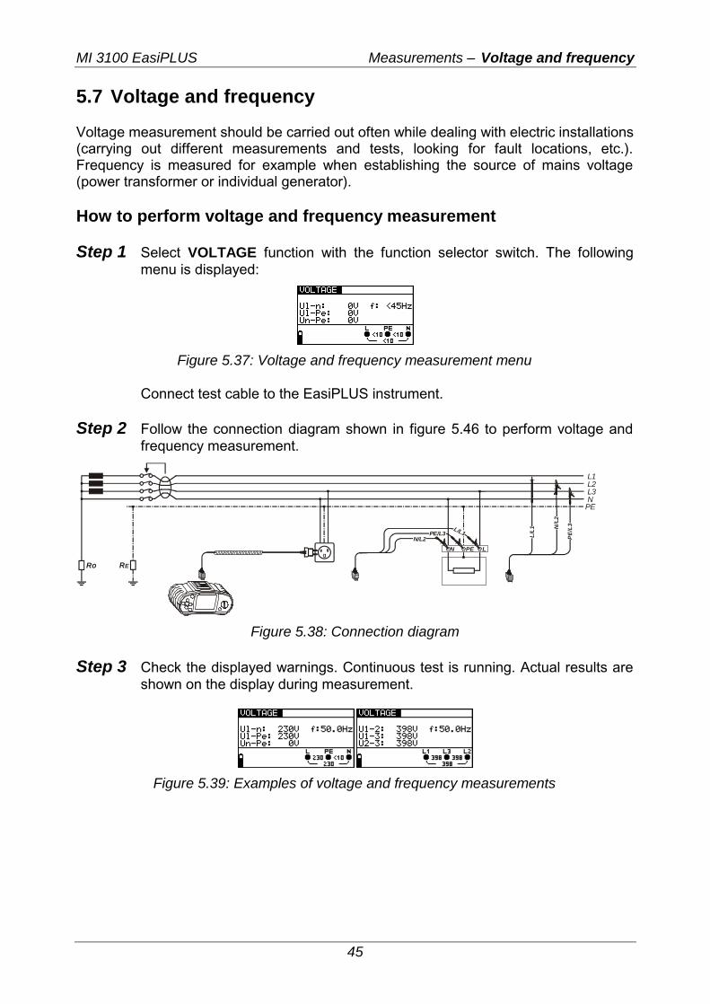
5.7 Voltage and frequency Voltage measurement should be carried out often while dealing with electric installations (carrying out different measurements and tests, looking for fault locations, etc.). Frequency is measured for example when establishing the source of mains voltage (power transformer or individual generator). How to perform voltage and frequency measurement Step 1 Select VOLTAGE function with the function selector switch. The following
menu is displayed:
Figure 5.37: Voltage and frequency measurement menu
Connect test cable to the EasiPLUS instrument.
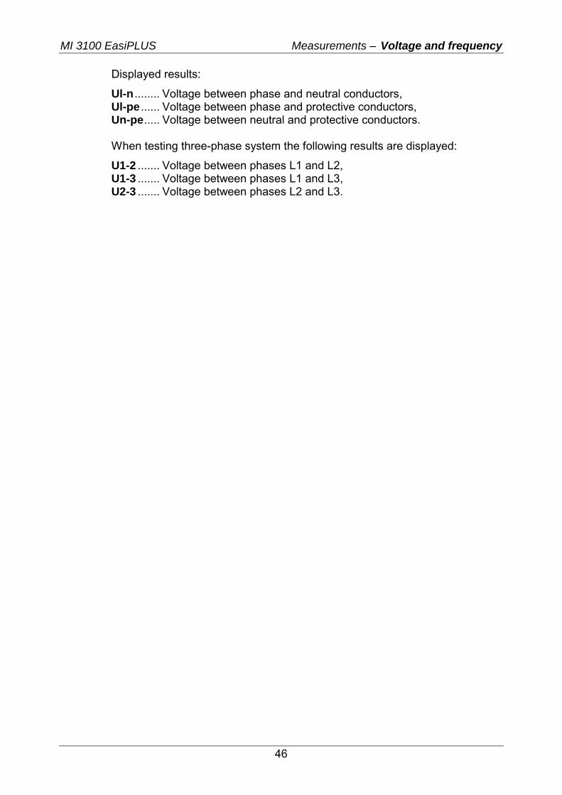
Step 2 Follow the connection diagram shown in figure 5.46 to perform voltage and frequency measurement.
L1L2L3N
PE
RERo
LPEN
L/L1N/L2
PE/L3
N/L
2
L/L1
PE/
L3
Figure 5.38: Connection diagram
Step 3 Check the displayed warnings. Continuous test is running. Actual results are shown on the display during measurement.
Figure 5.39: Examples of voltage and frequency measurements
MI 3100 EasiPLUS Measurements – Voltage and frequency
46
Displayed results:
Ul-n ........ Voltage between phase and neutral conductors, Ul-pe ...... Voltage between phase and protective conductors, Un-pe..... Voltage between neutral and protective conductors. When testing three-phase system the following results are displayed:
U1-2 ....... Voltage between phases L1 and L2, U1-3 ....... Voltage between phases L1 and L3, U2-3 ....... Voltage between phases L2 and L3.
MI 3100 EasiPLUS Measurements – Testing PE terminal
47
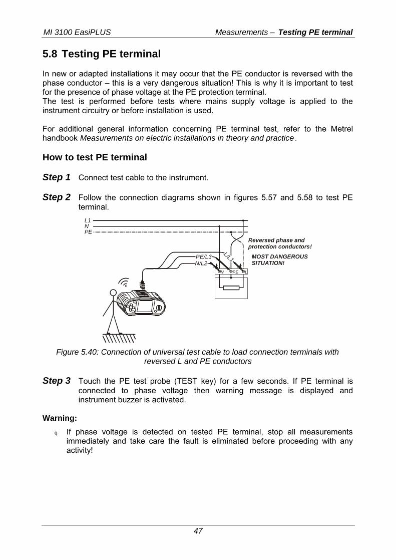
5.8 Testing PE terminal In new or adapted installations it may occur that the PE conductor is reversed with the phase conductor – this is a very dangerous situation! This is why it is important to test for the presence of phase voltage at the PE protection terminal. The test is performed before tests where mains supply voltage is applied to the instrument circuitry or before installation is used. For additional general information concerning PE terminal test, refer to the Metrel handbook Measurements on electric installations in theory and practice . How to test PE terminal Step 1 Connect test cable to the instrument. Step 2 Follow the connection diagrams shown in figures 5.57 and 5.58 to test PE
terminal.
L1N
Reversed phase and protection conductors!
MOST DANGEROUSSITUATION!
PE
LPEN
L/L1N/L2PE/L3
Figure 5.40: Connection of universal test cable to load connection terminals with
reversed L and PE conductors
Step 3 Touch the PE test probe (TEST key) for a few seconds. If PE terminal is connected to phase voltage then warning message is displayed and instrument buzzer is activated.
Warning:
q If phase voltage is detected on tested PE terminal, stop all measurements immediately and take care the fault is eliminated before proceeding with any activity!
MI 3100 EasiPLUS Measurements – Testing PE terminal
48
Notes:
q PE terminal can be tested in RCD, LOOP and LINE function selector switch positions only!
q For correct testing of PE terminal, the TEST key has to be touched for a few seconds.
q Make sure to stand on non-isolated floor while carrying out the test otherwise, test result may be wrong!

MI 3100 EasiPLUS Maintenance
49
6 Maintenance
6.1 Replacing fuses
There are three fuses under back cover of the EasiPLUS instrument.
q F1 M 0.315 A / 250 V, 20×5 mm This fuse protects internal circuitry of low-value resistance function if test probes are connected to the mains supply voltage by mistake.
q F2, F3 F 4 A / 500 V, 32×6.3 mm General input protection fuses of test terminals L/L1 and N/L2.
Warnings:
q Disconnect any measuring accessory and power off the instrument before opening battery/fuse compartment cover, hazardous voltage inside!
q Replace blown fuse with original one only, otherwise the instrument may be damaged and/or operator’s safety impaired!
Position of fuses can be seen in figure 3.4 in chapter 3.3 Back panel.
6.2 Cleaning
No special maintenance is required for the housing. To clean the surface of the instrument use a soft cloth slightly moistened with soapy water or alcohol. Then leave the instrument to dry totally before use.
Warnings:
q Do not use liquids based on petrol or hydrocarbons! q Do not spill cleaning liquid over the instrument!
6.3 Periodic calibration
It is essential that the test instrument is regularly calibrated in order technical specification listed in this manual can be guaranteed. We recommend an annual calibration. The calibration should be done by an authorised technical person only. Please contact your dealer for further information.
6.4 Service
For repairs under warranty, or at any other time, please contact your distributor.
Unauthorised person is not allowed to open the EasiPLUS instrument. There are no user replaceable components inside the instrument, except three fuses, refer to chapter 8.1 Replacing fuses.
MI 3100 EasiPLUS Technical specifications
50
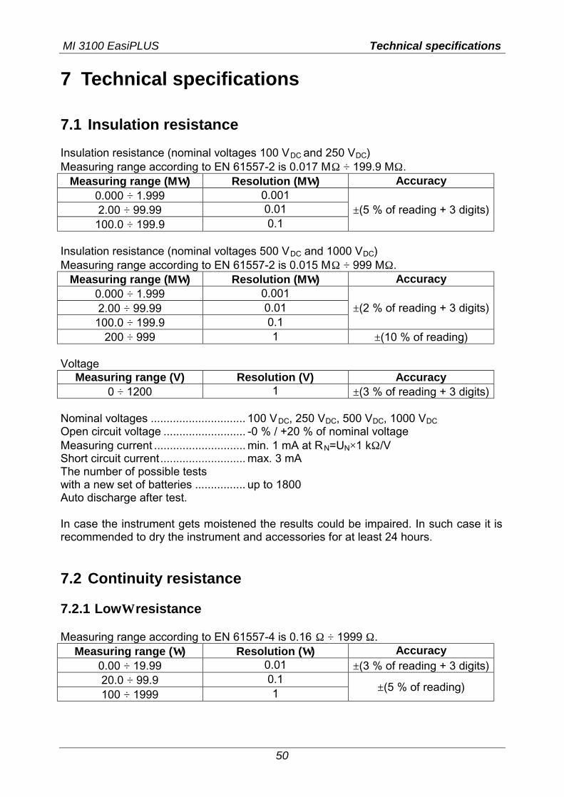
7 Technical specifications 7.1 Insulation resistance Insulation resistance (nominal voltages 100 VDC and 250 VDC) Measuring range according to EN 61557-2 is 0.017 MΩ ÷ 199.9 MΩ.
Measuring range (MΩ) Resolution (MΩ) Accuracy 0.000 ÷ 1.999 0.001 2.00 ÷ 99.99 0.01
100.0 ÷ 199.9 0.1 ±(5 % of reading + 3 digits)
Insulation resistance (nominal voltages 500 VDC and 1000 VDC) Measuring range according to EN 61557-2 is 0.015 MΩ ÷ 999 MΩ.
Measuring range (MΩ) Resolution (MΩ) Accuracy 0.000 ÷ 1.999 0.001 2.00 ÷ 99.99 0.01
100.0 ÷ 199.9 0.1 ±(2 % of reading + 3 digits)
200 ÷ 999 1 ±(10 % of reading) Voltage
Measuring range (V) Resolution (V) Accuracy 0 ÷ 1200 1 ±(3 % of reading + 3 digits)
Nominal voltages .............................. 100 VDC, 250 VDC, 500 VDC, 1000 VDC Open circuit voltage .......................... -0 % / +20 % of nominal voltage Measuring current ............................. min. 1 mA at RN=UN×1 kΩ/V Short circuit current........................... max. 3 mA The number of possible tests with a new set of batteries ................ up to 1800 Auto discharge after test. In case the instrument gets moistened the results could be impaired. In such case it is recommended to dry the instrument and accessories for at least 24 hours. 7.2 Continuity resistance 7.2.1 LowΩ resistance Measuring range according to EN 61557-4 is 0.16 Ω ÷ 1999 Ω.
Measuring range (Ω) Resolution (Ω) Accuracy 0.00 ÷ 19.99 0.01 ±(3 % of reading + 3 digits) 20.0 ÷ 99.9 0.1 100 ÷ 1999 1 ±(5 % of reading)
MI 3100 EasiPLUS Technical specifications
51
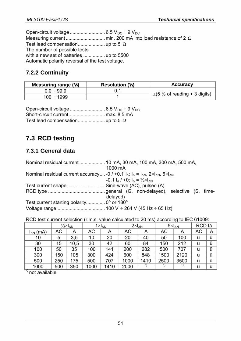
Open-circuit voltage .......................... 6.5 VDC ÷ 9 VDC Measuring current ............................. min. 200 mA into load resistance of 2 Ω Test lead compensation.................... up to 5 Ω The number of possible tests with a new set of batteries ................ up to 5500 Automatic polarity reversal of the test voltage. 7.2.2 Continuity
Measuring range (Ω) Resolution (Ω) Accuracy 0.0 ÷ 99.9 0.1
100 ÷ 1999 1 ±(5 % of reading + 3 digits)
Open-circuit voltage .......................... 6.5 VDC ÷ 9 VDC Short-circuit current........................... max. 8.5 mA Test lead compensation.................... up to 5 Ω 7.3 RCD testing 7.3.1 General data Nominal residual current ................... 10 mA, 30 mA, 100 mA, 300 mA, 500 mA,
1000 mA Nominal residual current accuracy.... -0 / +0.1⋅I∆; I∆ = I∆N, 2×I∆N, 5×I∆N -0.1⋅I∆ / +0; I∆ = ½×I∆N Test current shape ............................ Sine-wave (AC), pulsed (A) RCD type .......................................... general (G, non-delayed), selective (S, time-
delayed) Test current starting polarity.............. 0º or 180º
Voltage range.................................... 100 V ÷ 264 V (45 Hz ÷ 65 Hz) RCD test current selection (r.m.s. value calculated to 20 ms) according to IEC 61009:
½×I∆N 1×I∆N 2×I∆N 5×I∆N RCD I∆ I∆N (mA) AC A AC A AC A AC A AC A
10 5 3,5 10 20 20 40 50 100 ü ü 30 15 10,5 30 42 60 84 150 212 ü ü
100 50 35 100 141 200 282 500 707 ü ü 300 150 105 300 424 600 848 1500 2120 ü ü 500 250 175 500 707 1000 1410 2500 3500 ü ü
1000 500 350 1000 1410 2000 *) *) *) ü ü *) not available
MI 3100 EasiPLUS Technical specifications
52
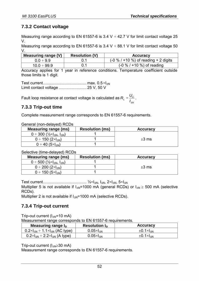
7.3.2 Contact voltage Measuring range according to EN 61557-6 is 3.4 V ÷ 42.7 V for limit contact voltage 25 V. Measuring range according to EN 61557-6 is 3.4 V ÷ 88.1 V for limit contact voltage 50 V. Measuring range (V) Resolution (V) Accuracy
0.0 ÷ 9.9 0.1 (-0 % / +10 %) of reading + 2 digits 10.0 ÷ 99.9 0.1 (-0 % / +10 %) of reading
Accuracy applies for 1 year in reference conditions. Temperature coefficient outside those limits is 1 digit.
Test current....................................... max. 0.5×I∆N Limit contact voltage ......................... 25 V, 50 V
Fault loop resistance at contact voltage is calculated asN
CL I
UR∆
= .
7.3.3 Trip-out time
Complete measurement range corresponds to EN 61557-6 requirements. General (non-delayed) RCDs
Measuring range (ms) Resolution (ms) Accuracy 0 ÷ 300 (½×I∆N, I∆N) 1
0 ÷ 150 (2×I∆N) 1 0 ÷ 40 (5×I∆N) 1
±3 ms
Selective (time-delayed) RCDs Measuring range (ms) Resolution (ms) Accuracy
0 ÷ 500 (½×I∆N, I∆N) 1 0 ÷ 200 (2×I∆N) 1 0 ÷ 150 (5×I∆N) 1
±3 ms
Test current....................................... ½×I∆N, I∆N, 2×I∆N, 5×I∆N
Multiplier 5 is not available if I∆N=1000 mA (general RCDs) or I∆N ≥ 500 mA (selective RCDs). Multiplier 2 is not available if I∆N=1000 mA (selective RCDs). 7.3.4 Trip-out current Trip-out current (I∆N=10 mA) Measurement range corresponds to EN 61557-6 requirements.
Measuring range I∆ Resolution I∆ Accuracy 0.2×I∆N ÷ 1.1×I∆N (AC type) 0.05×I∆N ±0.1×I∆N 0.2×I∆N ÷ 2.2×I∆N (A type) 0.05×I∆N ±0.1×I∆N
Trip-out current (I∆N≥30 mA) Measurement range corresponds to EN 61557-6 requirements.
MI 3100 EasiPLUS Technical specifications
53
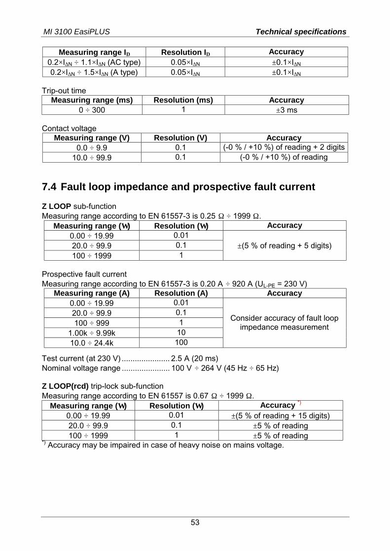
Measuring range I∆ Resolution I∆ Accuracy 0.2×I∆N ÷ 1.1×I∆N (AC type) 0.05×I∆N ±0.1×I∆N 0.2×I∆N ÷ 1.5×I∆N (A type) 0.05×I∆N ±0.1×I∆N
Trip-out time
Measuring range (ms) Resolution (ms) Accuracy 0 ÷ 300 1 ±3 ms
Contact voltage
Measuring range (V) Resolution (V) Accuracy 0.0 ÷ 9.9 0.1 (-0 % / +10 %) of reading + 2 digits
10.0 ÷ 99.9 0.1 (-0 % / +10 %) of reading 7.4 Fault loop impedance and prospective fault current Z LOOP sub-function Measuring range according to EN 61557-3 is 0.25 Ω ÷ 1999 Ω.
Measuring range (Ω) Resolution (Ω) Accuracy 0.00 ÷ 19.99 0.01 20.0 ÷ 99.9 0.1 100 ÷ 1999 1
±(5 % of reading + 5 digits)
Prospective fault current Measuring range according to EN 61557-3 is 0.20 A ÷ 920 A (UL-PE = 230 V)
Measuring range (A) Resolution (A) Accuracy 0.00 ÷ 19.99 0.01 20.0 ÷ 99.9 0.1 100 ÷ 999 1
1.00k ÷ 9.99k 10 10.0 ÷ 24.4k 100
Consider accuracy of fault loop impedance measurement
Test current (at 230 V) ...................... 2.5 A (20 ms) Nominal voltage range ...................... 100 V ÷ 264 V (45 Hz ÷ 65 Hz) Z LOOP(rcd) trip-lock sub-function Measuring range according to EN 61557 is 0.67 Ω ÷ 1999 Ω.
Measuring range (Ω) Resolution (Ω) Accuracy *) 0.00 ÷ 19.99 0.01 ±(5 % of reading + 15 digits) 20.0 ÷ 99.9 0.1 ±5 % of reading 100 ÷ 1999 1 ±5 % of reading
*) Accuracy may be impaired in case of heavy noise on mains voltage.
MI 3100 EasiPLUS Technical specifications
54
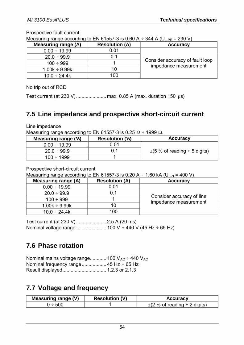
Prospective fault current Measuring range according to EN 61557-3 is 0.60 A ÷ 344 A (UL-PE = 230 V)
Measuring range (A) Resolution (A) Accuracy 0.00 ÷ 19.99 0.01 20.0 ÷ 99.9 0.1 100 ÷ 999 1
1.00k ÷ 9.99k 10 10.0 ÷ 24.4k 100
Consider accuracy of fault loop impedance measurement
No trip out of RCD
Test current (at 230 V) ...................... max. 0.85 A (max. duration 150 µs) 7.5 Line impedance and prospective short-circuit current Line impedance Measuring range according to EN 61557-3 is 0.25 Ω ÷ 1999 Ω.
Measuring range (Ω) Resolution (Ω) Accuracy 0.00 ÷ 19.99 0.01 20.0 ÷ 99.9 0.1 100 ÷ 1999 1
±(5 % of reading + 5 digits)
Prospective short-circuit current Measuring range according to EN 61557-3 is 0.20 A ÷ 1.60 kA (UL-N = 400 V)
Measuring range (A) Resolution (A) Accuracy 0.00 ÷ 19.99 0.01 20.0 ÷ 99.9 0.1 100 ÷ 999 1
1.00k ÷ 9.99k 10 10.0 ÷ 24.4k 100
Consider accuracy of line impedance measurement
Test current (at 230 V) ...................... 2.5 A (20 ms) Nominal voltage range ...................... 100 V ÷ 440 V (45 Hz ÷ 65 Hz) 7.6 Phase rotation Nominal mains voltage range............ 100 VAC ÷ 440 VAC Nominal frequency range.................. 45 Hz ÷ 65 Hz Result displayed................................ 1.2.3 or 2.1.3 7.7 Voltage and frequency
Measuring range (V) Resolution (V) Accuracy 0 ÷ 500 1 ±(2 % of reading + 2 digits)

MI 3100 EasiPLUS Technical specifications
55
Nominal frequency range.................. 0 Hz, 45 Hz ÷ 65 Hz
Measuring range (Hz) Resolution (Hz) Accuracy 45.0 ÷ 65.0 0.1 ± 2 digits
Nominal voltage range ...................... 10 V ÷ 500 V 7.8 Online voltage monitor
Measuring range (V) Resolution (V) Accuracy 0 ÷ 500 1 ±(2 % of reading + 2 digits)
Nominal frequency range.................. 0 Hz, 45 Hz ÷ 65 Hz If voltage greater than 500 V is applied to the test terminals, online voltage monitor is used as voltage indicator only. 7.9 General data Power supply voltage ........................ 9 VDC (6×1.5 V battery or accu, size AA) Power supply adapter ....................... 12 V ÷ 15 V / 400 mA Operation .......................................... typical 15 h Overvoltage category ........................ CAT III / 600 V Protection classification .................... double insulation Pollution degree ................................ 2 Protection degree.............................. IP 42 Display ............................................ 128×64 dots matrix display with backlight Dimensions (w × h × d) ..................... 23 cm × 10.3 cm × 11.5 cm Weight (without batteries) ................. 1.31 kg Reference conditions
Reference temperature range ........ 10 OC ÷ 30 OC Reference humidity range .............. 40 %RH ÷ 70 %RH
Operating conditions
Working temperature range ........... 0 OC ÷ 40 OC Maximum relative humidity............. 95 %RH (0 OC ÷ 40 OC), non-condensing
Storage conditions
Temperature range ........................ -10 OC ÷ +70 OC Maximum relative humidity............. 90 %RH (-10 OC ÷ +40 OC)
80 %RH (40 OC ÷ 60 OC) The error in operating conditions could be at most the error for reference conditions (specified in the manual for each function) + 1 % of measured value + 1 digit unless otherwise specified.
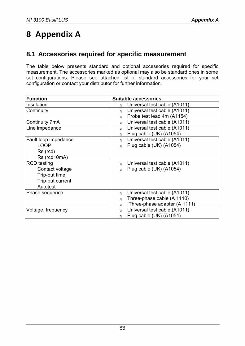
MI 3100 EasiPLUS Appendix A
56
8 Appendix A 8.1 Accessories required for specific measurement The table below presents standard and optional accessories required for specific measurement. The accessories marked as optional may also be standard ones in some set configurations. Please see attached list of standard accessories for your set configuration or contact your distributor for further information. Function Suitable accessories Insulation q Universal test cable (A1011) Continuity q Universal test cable (A1011)
q Probe test lead 4m (A1154) Continuity 7mA q Universal test cable (A1011) Line impedance q Universal test cable (A1011)
q Plug cable (UK) (A1054) Fault loop impedance
LOOP Rs (rcd) Rs (rcd10mA)
q Universal test cable (A1011) q Plug cable (UK) (A1054)
RCD testing Contact voltage Trip-out time Trip-out current Autotest
q Universal test cable (A1011) q Plug cable (UK) (A1054)
Phase sequence q Universal test cable (A1011) q Three-phase cable (A 1110) q Three-phase adapter (A 1111)
Voltage, frequency q Universal test cable (A1011) q Plug cable (UK) (A1054)