mi3250 instruction manual - metrel.si · 2 distributor: manufacturer: metrel d.d. ljubljanska cesta...
TRANSCRIPT
Earth Analyser MI 3290
Instruction manual Version 1.1.2, Code No. 20 752 597
2
Distributor: Manufacturer: METREL d.d. Ljubljanska cesta 77 1354 Horjul Slovenia web site: http://www.metrel.si e-mail: [email protected]
Mark on your equipment certifies that it meets European Union requirements for EMC, LVD, ROHS regulations.
© 2016 METREL
The trade names Metrel, Smartec, Eurotest, Autosequence are trademarks registered or pending in Europe and other countries. No part of this publication may be reproduced or utilized in any form or by any means without permission in writing from METREL.
MI 3290 Earth Analyser Table of contents
3
Table of contents
1 General Description ............................................................................................ 7
1.1 Features ........................................................................................................ 7
2 Safety and operational considerations ............................................................. 8 2.1 Warnings and notes ...................................................................................... 8 2.2 Battery and charging of Li-ion battery pack ................................................. 10
2.2.1 Precharge ............................................................................... 11
2.2.2 Li – ion battery pack guidelines ............................................... 13 2.3 Standards applied ....................................................................................... 14
3 Terms and definitions ....................................................................................... 15
4 Instrument description ..................................................................................... 16 4.1 Instrument casing ....................................................................................... 16
4.2 Operator’s panel ......................................................................................... 16
5 Accessories ....................................................................................................... 18 5.1 Standard set ............................................................................................... 18 5.2 Optional accessories................................................................................... 18
6 Instrument operation ........................................................................................ 19 6.1 General meaning of keys ............................................................................ 19
6.2 General meaning of touch gestures ............................................................ 19
6.3 Virtual keyboard .......................................................................................... 20
6.4 Display and sound ...................................................................................... 21
6.4.1 Battery and time indication ..................................................... 21
6.4.2 Messages ................................................................................ 21
6.4.3 Sound indication .................................................................... 23
6.4.4 Help screens ........................................................................... 24
7 Main menu ......................................................................................................... 25
7.1 Instruments main menu .............................................................................. 25
8 General Settings ................................................................................................ 26 8.1 Language .................................................................................................... 27
8.2 Power Save ................................................................................................ 27
8.3 Date and time ............................................................................................. 28
8.4 Instrument profiles ...................................................................................... 28 8.5 Settings ....................................................................................................... 29
8.6 Initial Settings ............................................................................................. 30 8.7 About .......................................................................................................... 30 8.8 Auto Test Groups ........................................................................................ 31
8.8.1 Auto test groups menu ........................................................... 31
8.8.2 Operations in Auto test groups menu: ..................................... 31
8.8.3 Selecting a list of Auto tests .................................................... 32
8.8.4 Deleting a list of Auto tests ..................................................... 32 8.9 Workspace manager ................................................................................... 33
8.9.1 Workspaces and Exports......................................................... 33
8.9.2 Workspace Manager main menu ............................................. 33
8.9.3 Operations with Workspaces ................................................... 34
8.9.4 Operations with Exports ......................................................... 34
8.9.5 Adding a new Workspace ........................................................ 35
MI 3290 Earth Analyser Table of contents
4
8.9.6 Opening a Workspace ............................................................. 36
8.9.7 Deleting a Workspace / Export ............................................... 36
8.9.8 Importing a Workspace ........................................................... 37
8.9.9 Exporting a Workspace ........................................................... 37
9 Memory Organizer ............................................................................................. 39 9.1 Memory Organizer menu ............................................................................ 39
9.1.1 Measurement statuses ............................................................ 39
9.1.2 Structure items....................................................................... 40
9.1.3 Measurement status indication under the Structure item ....... 40
9.1.4 Operations in Tree menu ........................................................ 41
10 Single tests ........................................................................................................ 53 10.1 Selection modes ......................................................................................... 53
10.1.1 Single test screens .................................................................. 54
10.1.2 Setting parameters and limits of single tests ........................... 55
10.1.3 Single test result screen .......................................................... 56
10.1.4 Graph view ............................................................................. 57
10.1.5 Recall single test result screen ................................................ 58
11 Tests and Measurements ................................................................................. 59
11.1 Earth Measurements [Ze and Re] ............................................................... 59
11.1.1 2 – pole Measurement ............................................................. 60
11.1.2 3 – pole Measurement ............................................................. 62
11.1.3 4 – pole Measurement ............................................................. 64
11.1.4 Selective (Iron Clamp) Measurement ....................................... 66
11.1.5 2 Clamps Measurement .......................................................... 68
11.1.6 HF-Earth Resistance (25 kHz) Measurement ........................... 70
11.1.7 Selective (Flex Clamps 1 - 4) Measurement.............................. 72
11.1.8 Passive (Flex Clamps) Measurement ........................................ 74
11.2 Specific Earth Resistance Measurements [ρ] ............................................. 76
11.2.1 General on specific earth ........................................................ 76
11.2.2 Wenner method Measurement ................................................ 77
11.2.3 Schlumberger method Measurement ....................................... 79
11.3 Impulse Impedance [Zp] ............................................................................. 81
11.3.1 Impulse Measurement ............................................................ 81
11.4 DC Resistance [R] ...................................................................................... 83
11.4.1 Ω - Meter (200 mA) Measurement ............................................ 83
11.4.2 Ω - Meter (7 mA) Measurement ............................................... 84
11.5 AC Impedance [Z] ....................................................................................... 86
11.5.1 Impedance Meter Measurement .............................................. 86
11.6 Earth Potential [Vp] ..................................................................................... 88
11.6.1 Potential Measurement ........................................................... 89
11.6.2 Step and Touch Voltages Theory ............................................. 91
11.7 Pylon Ground Wire Test (PGWT) ............................................................... 93
11.7.1 PGWT Measurement ............................................................... 93
11.8 Current [I] .................................................................................................... 95
11.8.1 Iron Clamp Meter RMS Measurement ...................................... 96
11.8.2 Flex Clamp Meter RMS Measurement...................................... 97
11.9 Checkbox .................................................................................................... 98
11.9.1 Check V - Meter Measurement ................................................ 99
MI 3290 Earth Analyser Table of contents
5
11.9.2 Check A - Meter Measurement .............................................. 100
11.9.3 Check Iron, Flex Clamps Measurement ................................. 101
12 Auto Tests........................................................................................................ 102
12.1 Selection of Auto tests .............................................................................. 102 12.2 Organization of Auto tests ......................................................................... 103
12.2.1 Auto test view menu ............................................................. 103
12.2.2 Step by step executions of Auto tests .................................... 105
12.2.3 Auto test result screen .......................................................... 106
12.2.4 Auto test memory screen ...................................................... 108
13 Communication ............................................................................................... 109
14 Maintenance .................................................................................................... 110
14.1 Cleaning .................................................................................................... 110 14.2 Periodic calibration ................................................................................... 110 14.3 Service ...................................................................................................... 110 14.4 Upgrading the instrument .......................................................................... 110
15 Technical specifications ................................................................................. 111
15.1 Earth [Ze] .................................................................................................. 111
15.1.1 2, 3, 4 - pole ......................................................................... 111
15.1.2 Selective (Iron Clamp) ........................................................... 112
15.1.3 2 Clamps .............................................................................. 113
15.1.4 Passive (Flex Clamps 1-4) ..................................................... 113
15.1.5 HF Earth Resistance (25 kHz) ............................................... 114
15.1.6 Selective (Flex Clamps 1 - 4) ................................................. 115
15.2 Specific Earth Resistance Measurements [ρ] ........................................... 116
15.2.1 Wenner and Schlumberger method ....................................... 116
15.3 Earth Potential [Vp] ................................................................................... 117
15.3.1 Potential ratio ....................................................................... 117
15.3.2 S&T Current Source ............................................................. 117
15.4 Impulse Impedance [Zp] ........................................................................... 118
15.4.1 Impulse Measurement .......................................................... 118
15.5 DC Resistance [R] .................................................................................... 119
15.5.1 Ω - Meter (200mA) ................................................................ 119
15.5.2 Ω - Meter (7mA) .................................................................... 120 15.6 AC Impedance [Z] ..................................................................................... 121
15.6.1 Impedance Meter .................................................................. 121 15.7 Current [I] .................................................................................................. 121
15.7.1 Iron Clamp Meter RMS ......................................................... 121
15.7.2 Flex Clamps Meter RMS ........................................................ 122 15.8 Influence of the auxiliary electrodes .......................................................... 123 15.9 Influence of low test current through clamps ............................................. 124
15.10 Influence of noise ...................................................................................... 125 15.11 Sub-results in measurement functions ...................................................... 126
15.12 General data ............................................................................................. 127
Appendix A – Structure objects ........................................................................... 128
Appendix B – Profiles Selection Table ................................................................ 129
Appendix C – Functionality and placing of test probes .................................... 130
MI 3290 Earth Analyser Table of contents
6
Appendix D – Pulse and 3-pole example ............................................................ 134
Appendix E - Programming of Auto tests on Metrel ES Manager ................... 135

MI 3290 Earth Analyser General Description
7
1 General Description
1.1 Features Earth Analyser (MI 3290) is a Multi-function, portable battery (Li-ion) or mains powered test instrument with excellent IP protection: IP65 (case closed), IP54 (case opened), intended for diagnosing of: Earth Resistance, Earth Impedance, Selective Earth Impedance, Specific Earth Resistance, Earth Potential, DC Resistance, AC Impedance and Impulse Impedance. It is designed and produced with the extensive knowledge and experience acquired through many years of working in this field. Available functions and features offered by the Earth Analyser:
Earth Impedance or Resistance 2, 3, 4 – pole; Selective Earth Impedance (Iron Clamp and up to 4 Flex Clamps); 2 Clamps Measurement; HF - Earth Resistance (25 kHz); Passive (Flex Clamps 1 - 4) method; Specific Earth Resistance ρ (Wenner, Schlumberger method); Ω - Meter (7 mA and 200 mA); AC Impedance Meter (55 Hz – 15 kHz); Impulse Impedance (10/350 µs); Earth Potential and Step & Touch Current Source (200 mA); Pylon Ground Wire Test; Current RMS Measurement (Iron and Flex Clamps); Checkbox; Auto Tests; Memory Organizer.
A 4.3'' (10.9 cm) colour LCD display with touch screen offers easy-to-read results and all associated parameters. The operation is straightforward and clear to enable the user to operate the instrument without the need for special training (except reading and understanding this Instruction Manual). Test results can be stored on the instrument. PC software that is supplied as a part of standard set enables transfer of measured results to PC where can be analysed or printed.
MI 3290 Earth Analyser according to
2 – pole 3 – pole 4 – pole
EN 61557 – 5 [Resistance to earth] IEEE Std 81 – 2012 [Two-point method, Three-point method, Fall-of-potential method]
2 Clamps IEEE Std 81 – 2012 [Resistance measurements by clamp-on stakeless method]
Selective (Flex Clamps 1 – 4) Selective (Iron Clamp)
IEEE Std 81 – 2012 [Resistance measurements by FOP/clamp-on method]
HF Earth Resistance (25 kHz) IEEE Std 81 – 1983 [High-Frequency Earth Resistance Meter]
Wenner Method IEEE Std 81 – 2012 [Four-point method (Equally Spaced or Wenner Arrangement)]
Schlumberger Method IEEE Std 81 – 2012 [Four-point method (Unequally Spaced or Schlumberger-Palmer Arrangement)]
Ω - Meter (200mA) EN 61557 – 4 [Resistance of earth connection and equipotential bonding]
MI 3290 Earth Analyser Safety and operational considerations
8
2 Safety and operational considerations
2.1 Warnings and notes In order to maintain the highest level of operator safety while carrying out various tests and measurements Metrel recommends keeping your Earth Analyser instruments in good condition and undamaged. When using the instrument, consider the following general warnings:
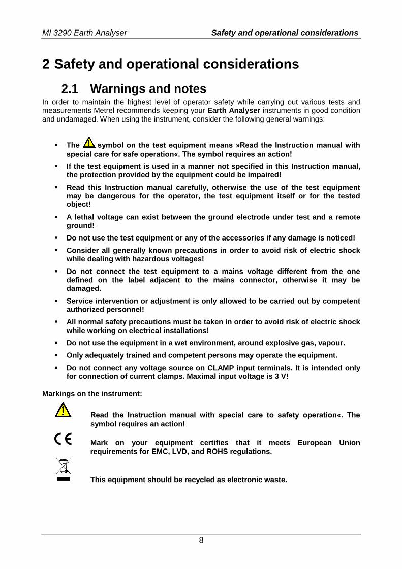
The symbol on the test equipment means »Read the Instruction manual with special care for safe operation«. The symbol requires an action!
If the test equipment is used in a manner not specified in this Instruction manual, the protection provided by the equipment could be impaired!
Read this Instruction manual carefully, otherwise the use of the test equipment may be dangerous for the operator, the test equipment itself or for the tested object!
A lethal voltage can exist between the ground electrode under test and a remote ground!
Do not use the test equipment or any of the accessories if any damage is noticed!
Consider all generally known precautions in order to avoid risk of electric shock while dealing with hazardous voltages!
Do not connect the test equipment to a mains voltage different from the one defined on the label adjacent to the mains connector, otherwise it may be damaged.
Service intervention or adjustment is only allowed to be carried out by competent authorized personnel!
All normal safety precautions must be taken in order to avoid risk of electric shock while working on electrical installations!
Do not use the equipment in a wet environment, around explosive gas, vapour.
Only adequately trained and competent persons may operate the equipment.
Do not connect any voltage source on CLAMP input terminals. It is intended only for connection of current clamps. Maximal input voltage is 3 V!
Markings on the instrument:
Read the Instruction manual with special care to safety operation«. The symbol requires an action!
Mark on your equipment certifies that it meets European Union requirements for EMC, LVD, and ROHS regulations.
This equipment should be recycled as electronic waste.
MI 3290 Earth Analyser Safety and operational considerations
9
Warnings related to measurement functions: Working with the instrument
Use only standard or optional test accessories supplied by your distributor!
Always connect accessories to the test equipment and to the test object before starting measurement. Do not touch test leads or crocodile clips during measurement.
Do not touch any conductive parts of equipment under test during the test, risk of electric shock!
Make sure that the tested object is disconnected (mains voltage disconnected) and de-energized, before connecting the test leads and starting the measurement!
Do not connect test terminals (H, S, ES, E) to an external voltage higher than 300 V DC or AC (CAT IV environment) to prevent any damage to the test equipment!
Do not use a current measurement as an indication that a circuit is safe to touch. A voltage measurement is necessary to know if a circuit is hazardous.
Warnings related to Batteries:
Use only batteries provided by the manufacturer. Never dispose of the batteries in a fire as it may cause them to explode or generate
a toxic gas. Do not attempt to disassemble, crush or puncture the batteries in any way. Do not short circuit or reverse polarity the external contacts on a battery. Keep the battery away from children. Avoid exposing the battery to excessive shock/impacts or vibration. Do not use a damaged battery. The Li – ion battery contains safety and protection circuit, which if damaged, may
cause the battery to generate heat, rupture or ignite. Do not leave a battery on prolonged charge when not in use. If a battery has leaking fluids, do not touch any fluids. In case of eye contact with fluid, do not rub eyes. Immediately flush eyes
thoroughly with water for at least 15 minutes, lifting upper and lower lids, until no evidence of the fluid remains. Seek medical attention.

MI 3290 Earth Analyser Safety and operational considerations
10
2.2 Battery and charging of Li-ion battery pack The instrument is designed to be powered by rechargeable Li-ion battery pack or with mains supply. The LCD contains an indication of battery condition and the power source (upper left section of LCD). In case the battery is too weak the instrument indicates this as shown in Figure 2.1.
Symbol:
Indication of low battery.
Figure 2.1: Battery test
The battery is charged whenever the power supply is connected to the instrument. The power supply socket is shown in Figure 2.2. Internal circuit controls (CC, CV) charging and assures maximum battery lifetime. Nominal operating time is declared for battery with nominal capacity of 4.4 Ah.
Figure 2.2: Power supply socket (C7)
The instrument automatically recognizes the connected power supply and begins charging.
Symbol:
Indication of battery charging
Figure 2.3: Charging indication (animation)
Battery and charging characteristic Typical
Battery type VB 18650
Charging mode CC / CV
Nominal voltage 14,8 V
Rated capacity 4,4 Ah
Max charging voltage 16,7 V
Max charging current 1,2 A
Max discharge current 2,5 A
Typical charging time 4 hours
MI 3290 Earth Analyser Safety and operational considerations
11
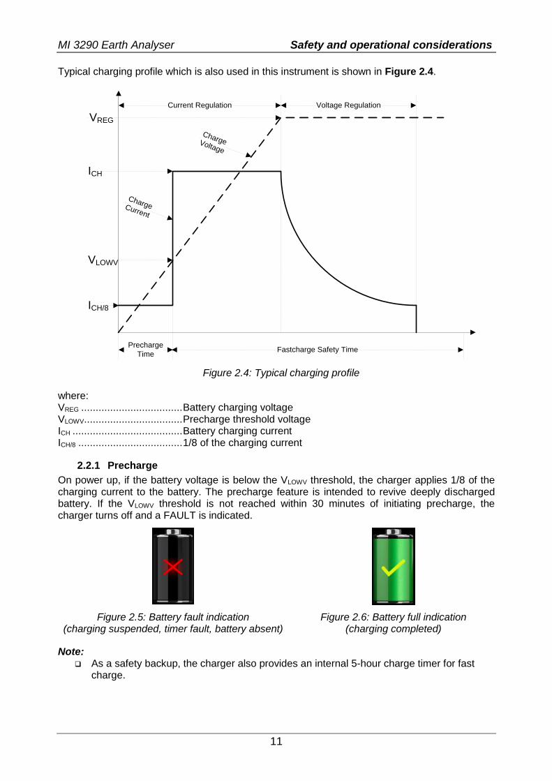
Typical charging profile which is also used in this instrument is shown in Figure 2.4.
ICH/8
Fastcharge Safety TimePrecharge
Time
Current Regulation Voltage Regulation
ICH
VREG
VLOWV
Charge Current
Charge Voltage
Figure 2.4: Typical charging profile
where: VREG ................................... Battery charging voltage VLOWV .................................. Precharge threshold voltage ICH ...................................... Battery charging current ICH/8 .................................... 1/8 of the charging current
2.2.1 Precharge
On power up, if the battery voltage is below the VLOWV threshold, the charger applies 1/8 of the charging current to the battery. The precharge feature is intended to revive deeply discharged battery. If the VLOWV threshold is not reached within 30 minutes of initiating precharge, the charger turns off and a FAULT is indicated.
Figure 2.5: Battery fault indication (charging suspended, timer fault, battery absent)
Figure 2.6: Battery full indication (charging completed)
Note: As a safety backup, the charger also provides an internal 5-hour charge timer for fast
charge.
MI 3290 Earth Analyser Safety and operational considerations
12
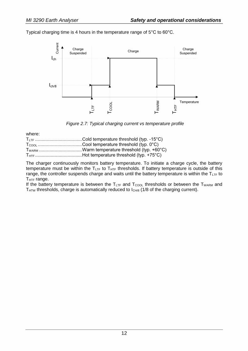
Typical charging time is 4 hours in the temperature range of 5°C to 60°C.
Ich/8
Ich
TL
TF
TC
OO
L
TW
AR
M
TH
TF
Charge
Suspended
Charge
Suspended
Temperature
Cu
rre
nt
Charge
Figure 2.7: Typical charging current vs temperature profile
where: TLTF .................................... Cold temperature threshold (typ. -15°C) TCOOL .................................. Cool temperature threshold (typ. 0°C) TWARM ................................. Warm temperature threshold (typ. +60°C) THTF .................................... Hot temperature threshold (typ. +75°C)
The charger continuously monitors battery temperature. To initiate a charge cycle, the battery temperature must be within the TLTF to THTF thresholds. If battery temperature is outside of this range, the controller suspends charge and waits until the battery temperature is within the TLTF to THTF range. If the battery temperature is between the TLTF and TCOOL thresholds or between the TWARM and THTW thresholds, charge is automatically reduced to ICH/8 (1/8 of the charging current).

MI 3290 Earth Analyser Safety and operational considerations
13
2.2.2 Li – ion battery pack guidelines
Li – ion rechargeable battery pack requires routine maintenance and care in their use and handling. Read and follow the guidelines in this Instruction manual to safely use Li – ion battery pack and achieve the maximum battery life cycles. Do not leave batteries unused for extended periods of time – more than 6 months (self – discharge). When a battery has been unused for 6 months, check the charge status see chapter 6.4.1
Battery and time indication. Rechargeable Li – ion battery pack has a limited life and will gradually lose their capacity to hold a charge. As the battery loses capacity, the length of time it will power the product decreases. Storage:
Charge or discharge the instruments battery pack to approximately 50% of capacity before storage.
Charge the instrument battery pack to approximately 50% of capacity at least once every 6 months.
Transportation:
Always check all applicable local, national, and international regulations before transporting a Li – ion battery pack.
Handling Warnings:
Do not disassemble, crush, or puncture a battery in any way. Do not short circuit or reverse polarity the external contacts on a battery. Do not dispose of a battery in fire or water. Keep the battery away from children. Avoid exposing the battery to excessive shock/impacts or vibration. Do not use a damaged battery. The Li – ion battery contains safety and protection circuit, which if damaged, may
cause the battery to generate heat, rupture or ignite. Do not leave a battery on prolonged charge when not in use. If a battery has leaking fluids, do not touch any fluids. In case of eye contact with fluid, do not rub eyes. Immediately flush eyes
thoroughly with water for at least 15 minutes, lifting upper and lower lids, until no evidence of the fluid remains. Seek medical attention.
MI 3290 Earth Analyser Safety and operational considerations
14
2.3 Standards applied The Earth Analyser instrument is manufactured and tested in accordance with the following regulations:
Electromagnetic compatibility (EMC) EN 61326 Electrical equipment for measurement, control and laboratory
use – EMC requirements Class A
Safety (LVD) EN 61010 - 1 Safety requirements for electrical equipment for measurement, control
and laboratory use – Part 1: General requirements EN 61010 - 2 - 030 Safety requirements for electrical equipment for measurement, control
and laboratory use – Part 2-030: Particular requirements for testing and measuring circuits
EN 61010 - 2 - 032 Safety requirements for electrical equipment for measurement, control and laboratory use – Part 2-032: Particular requirements for hand-held and hand-manipulated current sensors for electrical test and measurement.
EN 61010 - 031 Safety requirements for hand-held probe assemblies for electrical measurement and test.
Some further recommendations EN 61557 - 5 Electrical safety in low voltage distribution systems up to 1000 V a.c.
and 1500 V d.c. - Equipment for testing, measuring or monitoring of protective measures. Part 5: Resistance to earth.
IEEE 80 – 2000 IEEE Guide for Safety in AC Substation Grounding IEEE 81 – 2012 IEEE Guide for Measuring Earth Resistivity, Ground Impedance, and
Earth Surface Potentials of a Grounding System. IEEE 142 IEEE Recommended Practice for Grounding of Industrial and
Commercial Power Systems (US). IEEE 367 – 2012 IEEE Recommended Practice for Determining the Electric Power
Station Ground Potential Rise and Induced Voltage from a Power Fault.
Li – ion battery pack IEC 62133 Secondary cells and batteries containing alkaline or other non-acid
electrolytes - Safety requirements for portable sealed secondary cells, and for batteries made from them, for use in portable applications.
Note about EN and IEC standards:
Text of this manual contains references to European standards. All standards of EN 6XXXX (e.g. EN 61010) series are equivalent to IEC standards with the same number (e.g. IEC 61010) and differ only in amended parts required by European harmonization procedure.
MI 3290 Earth Analyser Terms and definitions
15
3 Terms and definitions For the purposes of this document and instrument Earth Analyser, the following definitions apply.
Index: Unit: Description:
Re [Ω] Earth resistance of complete system.
Ze [Ω] Earth impedance of complete system.
Rp [Ω] Auxiliary potential probe impedance.
Rc [Ω] Auxiliary current probe impedance.
Ie [A] System current or generator current.
f [Hz] Test frequency.
Ic [A] Iron clamp current.
Zsel [Ω] Earth impedance of measured branch.
Ztot [Ω] Total earth impedance of measured branches.
If1 [A] Flex clamp 1 current [F1 – terminal].
If2 [A] Flex clamp 2 current [F2 – terminal].
If3 [A] Flex clamp 3 current [F3 – terminal].
If4 [A] Flex clamp 4 current [F4 – terminal].
Zsel1 [Ω] Earth impedance of measured branch [F1 – terminal]. Zsel2 [Ω] Earth impedance of measured branch [F2 – terminal]. Zsel3 [Ω] Earth impedance of measured branch [F3 – terminal]. Zsel4 [Ω] Earth impedance of measured branch [F4 – terminal]. ρ [Ωm/ft] Specific earth resistance [resistivity].
R [Ω] Resistance [DC current].
Idc [A] DC current.
Z [Ω] Impedance [AC current].
Iac [A] AC current.
Vp [ ] Potential ratio [is defined as the inverted value of Us voltage divided by Uh voltage].
R [m] Total distance between E and auxiliary earth rod H.
r [m] Distance between E and S probe.
ϕ [°] Direction of potential measurement or angle [0° - 360°].
Igen [A] Generator current.
If_sum [A] Flex clamp current [If_sum = If1 + If2 + If3 + If4].
Uh [V] Uh voltage [H – terminal].
Us [V] Us voltage [S – terminal].
Ues [V] Ues voltage [ES – terminal].
Ig_w [A] Overhead ground wire current [Ig_w = Igen - If_sum].
R [Ω] Complex number [real number].
X [Ω] Complex number [Imaginary number].
φ [°] Phase angle between u and i.
Zp [Ω] Impulse impedance [is defined as the peak voltage divided by the peak current].
Up [V] Peak voltage.
Ip [A] Peak current.
Designation of the terminals:
E - terminal for the earth electrode; ES - terminal for the probe placed nearest to the earth electrode; S - terminal for a probe; H - terminal for the auxiliary earth electrode.
Notes (acc.to IEEE Std 81 - 2012): Earth Resistance – The impedance, excluding reactance, between a ground electrode,
grid or system and remote earth. Earth Impedance – The vector sum of resistance and reactance between a ground
electrode, grid or system and remote earth.
MI 3290 Earth Analyser Instrument description
16
4 Instrument description
4.1 Instrument casing The instrument is housed in a plastic box that maintains the protection class defined in the general specifications.
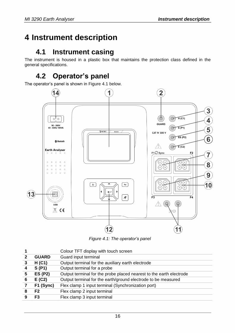
4.2 Operator’s panel The operator’s panel is shown in Figure 4.1 below.
Figure 4.1: The operator’s panel
1 Colour TFT display with touch screen
2 GUARD Guard input terminal
3 H (C1) Output terminal for the auxiliary earth electrode
4 S (P1) Output terminal for a probe
5 ES (P2) Output terminal for the probe placed nearest to the earth electrode
6 E (C2) Output terminal for the earth/ground electrode to be measured
7 F1 (Sync) Flex clamp 1 input terminal (Synchronization port)
8 F2 Flex clamp 2 input terminal
9 F3 Flex clamp 3 input terminal
MI 3290 Earth Analyser Instrument description
17
10 F4 Flex clamp 4 input terminal
11 CLAMP Iron clamp input terminal
12 Keypad (see section 6.1 General meaning of keys)
13 USB USB communication port (standard USB connector - type B)
14 Input power supply socket (type C7)
Warnings!
Do not connect test terminals (H, S, ES, E) to an external voltage higher than 300 V DC or AC (CAT IV environment) to prevent any damage to the test equipment!
Do not connect any voltage source on CLAMP input terminals. It is intended only for connection of current clamps. Maximal input voltage is 3 V!
Use original test accessories only!
MI 3290 Earth Analyser Accessories
18
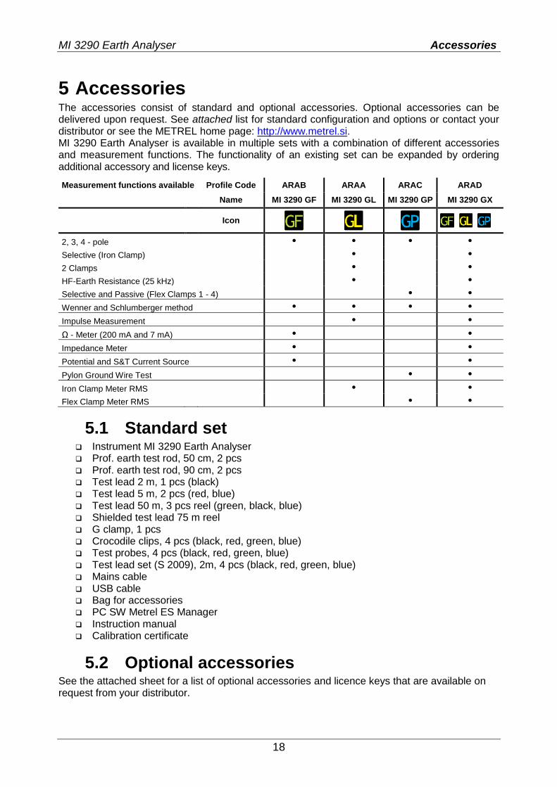
5 Accessories The accessories consist of standard and optional accessories. Optional accessories can be delivered upon request. See attached list for standard configuration and options or contact your distributor or see the METREL home page: http://www.metrel.si. MI 3290 Earth Analyser is available in multiple sets with a combination of different accessories and measurement functions. The functionality of an existing set can be expanded by ordering additional accessory and license keys.
Measurement functions available Profile Code ARAB ARAA ARAC ARAD
Name MI 3290 GF MI 3290 GL MI 3290 GP MI 3290 GX
Icon
2, 3, 4 - pole • • • •
Selective (Iron Clamp) • •
2 Clamps • •
HF-Earth Resistance (25 kHz) • •
Selective and Passive (Flex Clamps 1 - 4) • •
Wenner and Schlumberger method • • • •
Impulse Measurement • •
Ω - Meter (200 mA and 7 mA) • •
Impedance Meter • •
Potential and S&T Current Source • •
Pylon Ground Wire Test • •
Iron Clamp Meter RMS • •
Flex Clamp Meter RMS • •
5.1 Standard set Instrument MI 3290 Earth Analyser Prof. earth test rod, 50 cm, 2 pcs Prof. earth test rod, 90 cm, 2 pcs Test lead 2 m, 1 pcs (black) Test lead 5 m, 2 pcs (red, blue) Test lead 50 m, 3 pcs reel (green, black, blue) Shielded test lead 75 m reel G clamp, 1 pcs Crocodile clips, 4 pcs (black, red, green, blue) Test probes, 4 pcs (black, red, green, blue) Test lead set (S 2009), 2m, 4 pcs (black, red, green, blue) Mains cable USB cable Bag for accessories PC SW Metrel ES Manager Instruction manual Calibration certificate
5.2 Optional accessories See the attached sheet for a list of optional accessories and licence keys that are available on request from your distributor.
MI 3290 Earth Analyser Instrument operation
19
6 Instrument operation The Earth Analyser instrument can be manipulated via a keypad or touch screen.
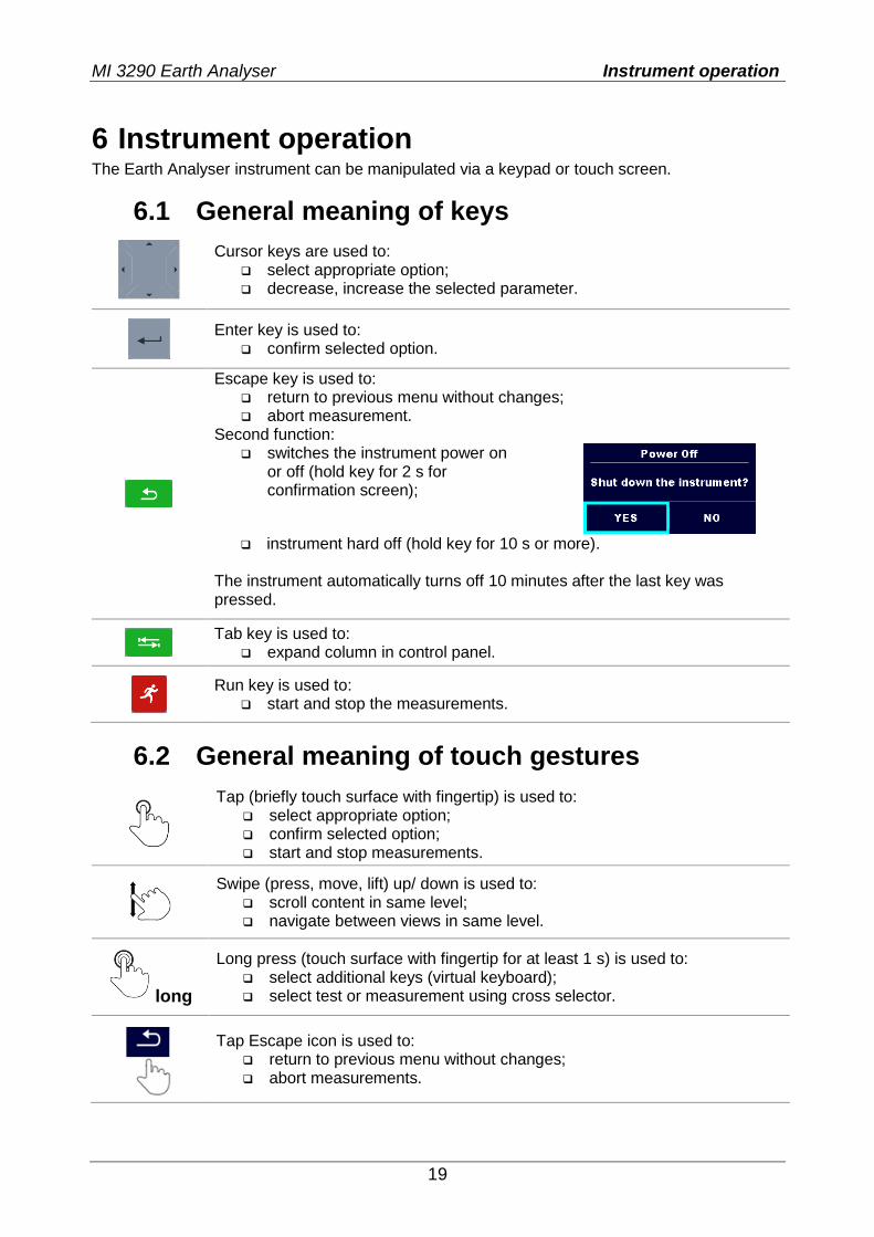
6.1 General meaning of keys
Cursor keys are used to: select appropriate option; decrease, increase the selected parameter.
Enter key is used to: confirm selected option.
Escape key is used to: return to previous menu without changes; abort measurement.
Second function: switches the instrument power on
or off (hold key for 2 s for confirmation screen);
instrument hard off (hold key for 10 s or more).
The instrument automatically turns off 10 minutes after the last key was pressed.
Tab key is used to:
expand column in control panel.
Run key is used to: start and stop the measurements.
6.2 General meaning of touch gestures
Tap (briefly touch surface with fingertip) is used to: select appropriate option; confirm selected option; start and stop measurements.
Swipe (press, move, lift) up/ down is used to: scroll content in same level; navigate between views in same level.
long
Long press (touch surface with fingertip for at least 1 s) is used to: select additional keys (virtual keyboard); select test or measurement using cross selector.
Tap Escape icon is used to: return to previous menu without changes; abort measurements.
MI 3290 Earth Analyser Instrument operation
20
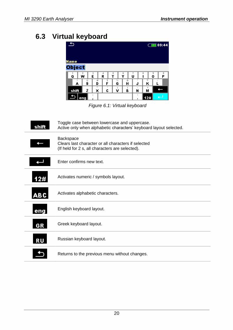
6.3 Virtual keyboard
Figure 6.1: Virtual keyboard
Toggle case between lowercase and uppercase. Active only when alphabetic characters’ keyboard layout selected.
Backspace Clears last character or all characters if selected (If held for 2 s, all characters are selected).
Enter confirms new text.
Activates numeric / symbols layout.
Activates alphabetic characters.
English keyboard layout.
Greek keyboard layout.
Russian keyboard layout.
Returns to the previous menu without changes.
MI 3290 Earth Analyser Instrument operation
21
6.4 Display and sound
6.4.1 Battery and time indication
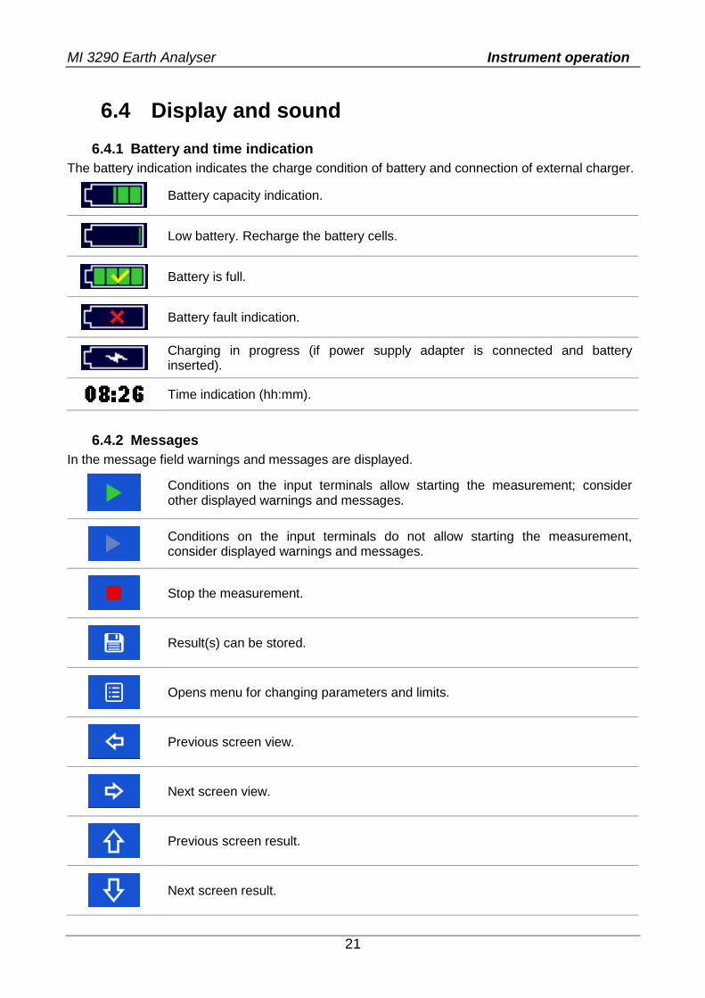
The battery indication indicates the charge condition of battery and connection of external charger.
Battery capacity indication.
Low battery. Recharge the battery cells.
Battery is full.
Battery fault indication.
Charging in progress (if power supply adapter is connected and battery inserted).
Time indication (hh:mm).
6.4.2 Messages
In the message field warnings and messages are displayed.
Conditions on the input terminals allow starting the measurement; consider other displayed warnings and messages.
Conditions on the input terminals do not allow starting the measurement, consider displayed warnings and messages.
Stop the measurement.
Result(s) can be stored.
Opens menu for changing parameters and limits.
Previous screen view.
Next screen view.
Previous screen result.
Next screen result.
MI 3290 Earth Analyser Instrument operation
22
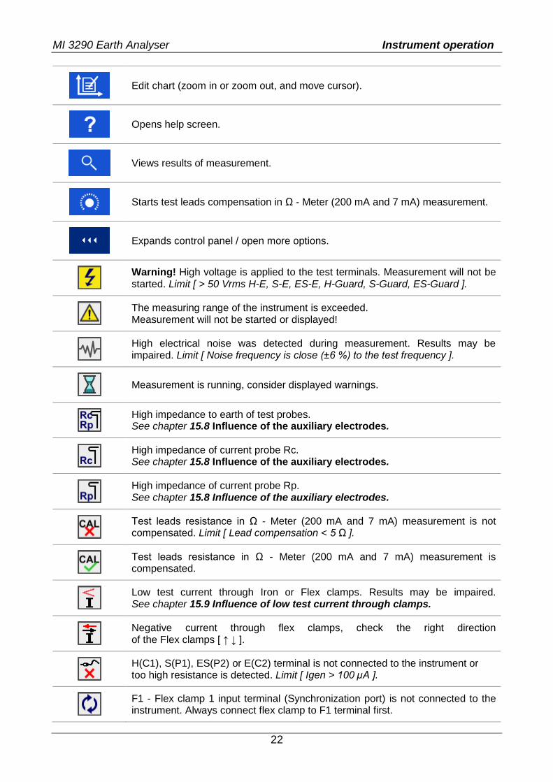
Edit chart (zoom in or zoom out, and move cursor).
Opens help screen.
Views results of measurement.
Starts test leads compensation in Ω - Meter (200 mA and 7 mA) measurement.
Expands control panel / open more options.
Warning! High voltage is applied to the test terminals. Measurement will not be started. Limit [ > 50 Vrms H-E, S-E, ES-E, H-Guard, S-Guard, ES-Guard ].
The measuring range of the instrument is exceeded. Measurement will not be started or displayed!
High electrical noise was detected during measurement. Results may be impaired. Limit [ Noise frequency is close (±6 %) to the test frequency ].
Measurement is running, consider displayed warnings.
High impedance to earth of test probes. See chapter 15.8 Influence of the auxiliary electrodes.
High impedance of current probe Rc. See chapter 15.8 Influence of the auxiliary electrodes.
High impedance of current probe Rp. See chapter 15.8 Influence of the auxiliary electrodes.
Test leads resistance in Ω - Meter (200 mA and 7 mA) measurement is not compensated. Limit [ Lead compensation < 5 Ω ].
Test leads resistance in Ω - Meter (200 mA and 7 mA) measurement is compensated.
Low test current through Iron or Flex clamps. Results may be impaired. See chapter 15.9 Influence of low test current through clamps.
Negative current through flex clamps, check the right direction of the Flex clamps [ ↑ ↓ ].
H(C1), S(P1), ES(P2) or E(C2) terminal is not connected to the instrument or too high resistance is detected. Limit [ Igen > 100 µA ].
F1 - Flex clamp 1 input terminal (Synchronization port) is not connected to the instrument. Always connect flex clamp to F1 terminal first.
MI 3290 Earth Analyser Instrument operation
23
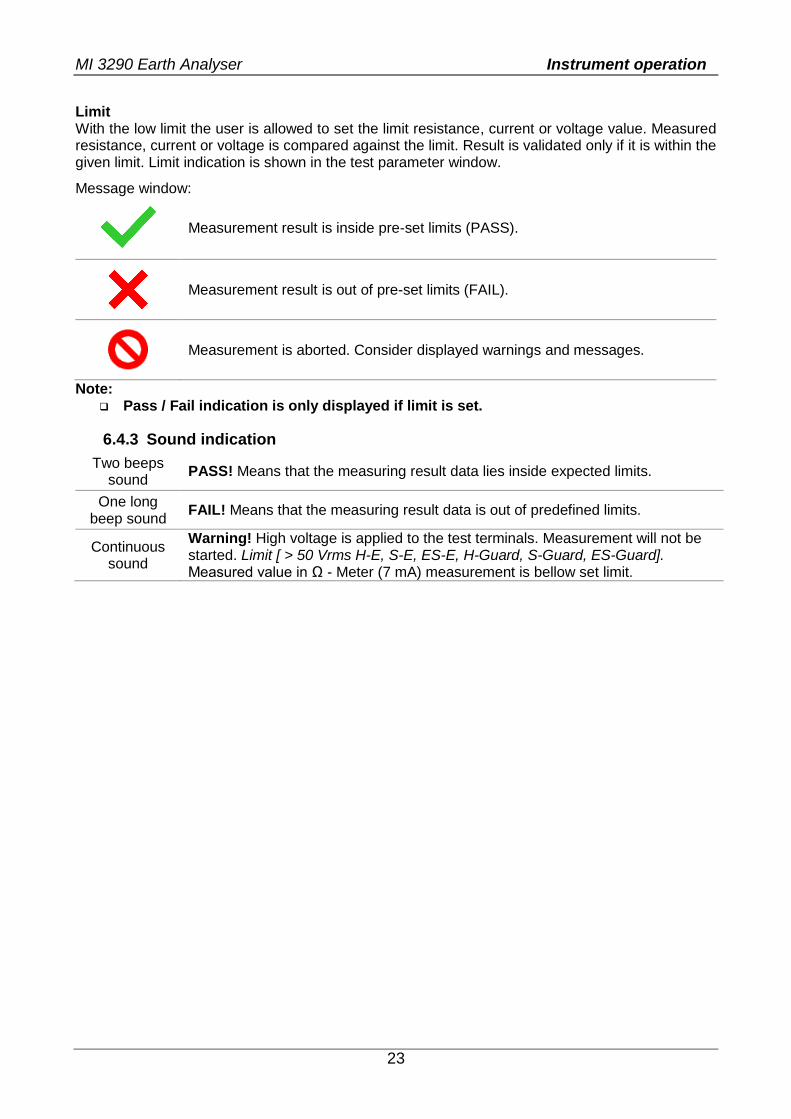
Limit With the low limit the user is allowed to set the limit resistance, current or voltage value. Measured resistance, current or voltage is compared against the limit. Result is validated only if it is within the given limit. Limit indication is shown in the test parameter window.
Message window:
Measurement result is inside pre-set limits (PASS).
Measurement result is out of pre-set limits (FAIL).
Measurement is aborted. Consider displayed warnings and messages.
Note: Pass / Fail indication is only displayed if limit is set.
6.4.3 Sound indication
Two beeps sound
PASS! Means that the measuring result data lies inside expected limits.
One long beep sound
FAIL! Means that the measuring result data is out of predefined limits.
Continuous sound
Warning! High voltage is applied to the test terminals. Measurement will not be started. Limit [ > 50 Vrms H-E, S-E, ES-E, H-Guard, S-Guard, ES-Guard]. Measured value in Ω - Meter (7 mA) measurement is bellow set limit.
MI 3290 Earth Analyser Instrument operation
24
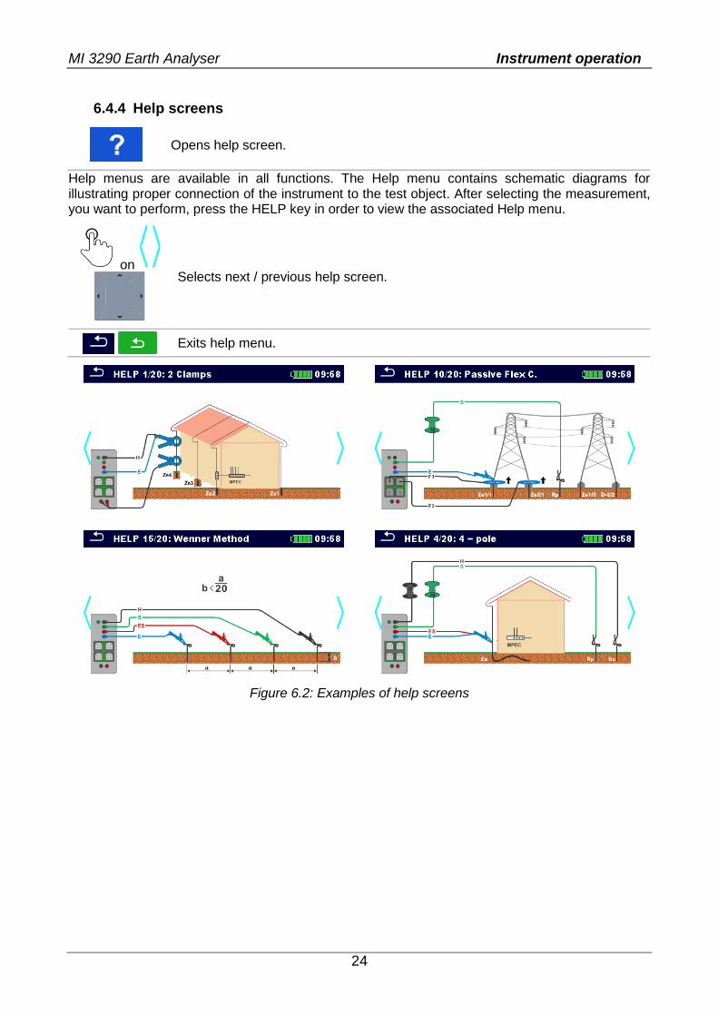
6.4.4 Help screens
Opens help screen.
Help menus are available in all functions. The Help menu contains schematic diagrams for illustrating proper connection of the instrument to the test object. After selecting the measurement, you want to perform, press the HELP key in order to view the associated Help menu.
on
Selects next / previous help screen.
Exits help menu.
Figure 6.2: Examples of help screens
MI 3290 Earth Analyser Main menu
25
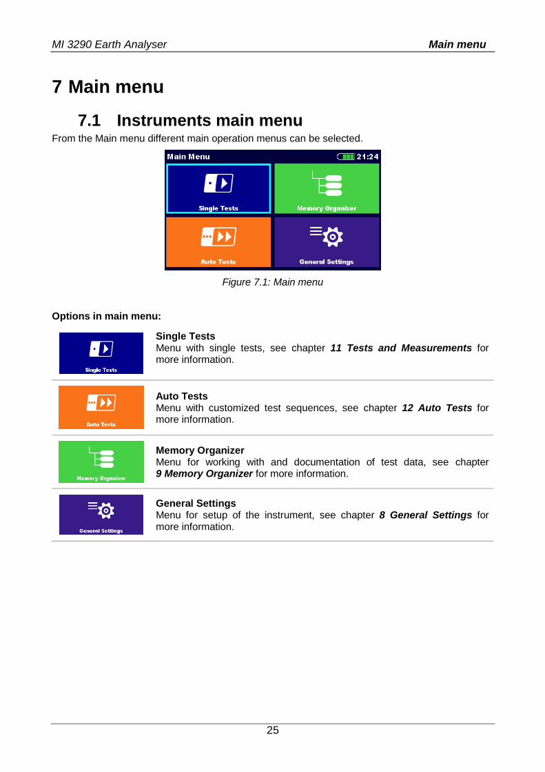
7 Main menu
7.1 Instruments main menu From the Main menu different main operation menus can be selected.
Figure 7.1: Main menu
Options in main menu:
Single Tests Menu with single tests, see chapter 11 Tests and Measurements for more information.
Auto Tests Menu with customized test sequences, see chapter 12 Auto Tests for more information.
Memory Organizer Menu for working with and documentation of test data, see chapter 9 Memory Organizer for more information.
General Settings Menu for setup of the instrument, see chapter 8 General Settings for more information.
MI 3290 Earth Analyser General Settings
26
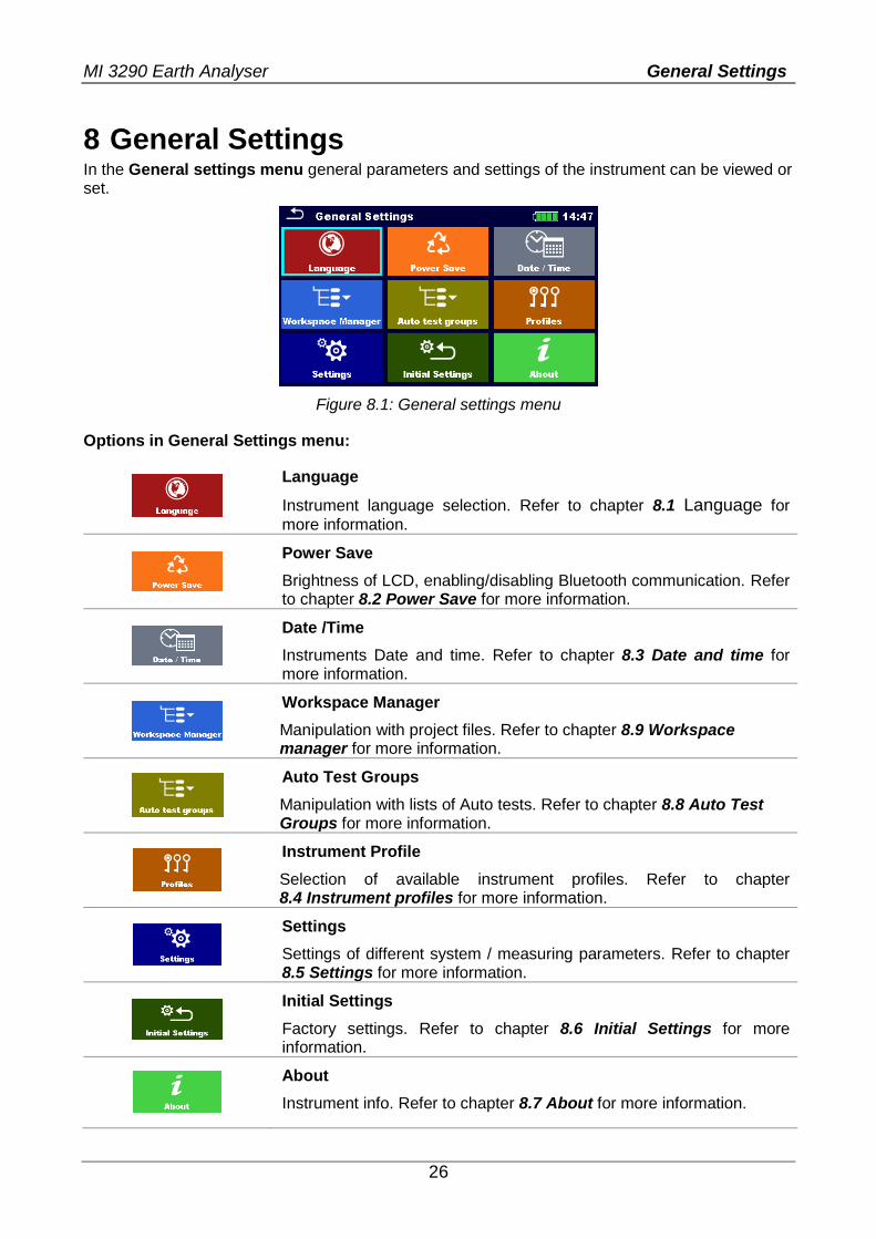
8 General Settings In the General settings menu general parameters and settings of the instrument can be viewed or set.
Figure 8.1: General settings menu
Options in General Settings menu:
Language
Instrument language selection. Refer to chapter 8.1 Language for
more information.
Power Save
Brightness of LCD, enabling/disabling Bluetooth communication. Refer to chapter 8.2 Power Save for more information.
Date /Time
Instruments Date and time. Refer to chapter 8.3 Date and time for more information.
Workspace Manager
Manipulation with project files. Refer to chapter 8.9 Workspace manager for more information.
Auto Test Groups
Manipulation with lists of Auto tests. Refer to chapter 8.8 Auto Test Groups for more information.
Instrument Profile
Selection of available instrument profiles. Refer to chapter 8.4 Instrument profiles for more information.
Settings
Settings of different system / measuring parameters. Refer to chapter 8.5 Settings for more information.
Initial Settings
Factory settings. Refer to chapter 8.6 Initial Settings for more information.
About
Instrument info. Refer to chapter 8.7 About for more information.
MI 3290 Earth Analyser General Settings
27
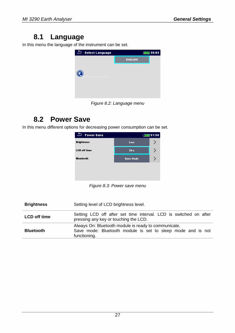
8.1 Language In this menu the language of the instrument can be set.
Figure 8.2: Language menu
8.2 Power Save In this menu different options for decreasing power consumption can be set.
Figure 8.3: Power save menu
Brightness Setting level of LCD brightness level.
LCD off time Setting LCD off after set time interval. LCD is switched on after pressing any key or touching the LCD.
Bluetooth Always On: Bluetooth module is ready to communicate. Save mode: Bluetooth module is set to sleep mode and is not functioning.
MI 3290 Earth Analyser General Settings
28
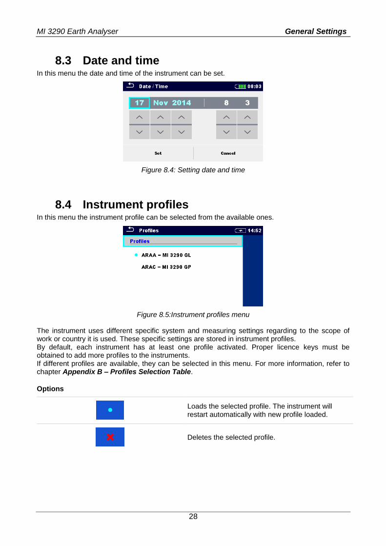
8.3 Date and time In this menu the date and time of the instrument can be set.
Figure 8.4: Setting date and time
8.4 Instrument profiles In this menu the instrument profile can be selected from the available ones.
Figure 8.5:Instrument profiles menu
The instrument uses different specific system and measuring settings regarding to the scope of work or country it is used. These specific settings are stored in instrument profiles. By default, each instrument has at least one profile activated. Proper licence keys must be obtained to add more profiles to the instruments. If different profiles are available, they can be selected in this menu. For more information, refer to chapter Appendix B – Profiles Selection Table.
Options
Loads the selected profile. The instrument will restart automatically with new profile loaded.
Deletes the selected profile.
MI 3290 Earth Analyser General Settings
29
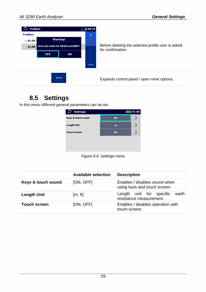
Before deleting the selected profile user is asked for confirmation.
Expands control panel / open more options.
8.5 Settings In this menu different general parameters can be set.
Figure 8.6: Settings menu
Available selection Description
Keys & touch sound [ON, OFF] Enables / disables sound when using keys and touch screen.
Length Unit [m, ft] Length unit for specific earth resistance measurement.
Touch screen [ON, OFF] Enables / disables operation with touch screen.
MI 3290 Earth Analyser General Settings
30
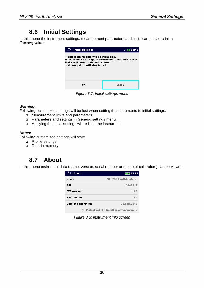
8.6 Initial Settings In this menu the instrument settings, measurement parameters and limits can be set to initial (factory) values.
Figure 8.7: Initial settings menu
Warning: Following customized settings will be lost when setting the instruments to initial settings:
Measurement limits and parameters. Parameters and settings in General settings menu. Applying the initial settings will re-boot the instrument.
Notes: Following customized settings will stay:
Profile settings. Data in memory.
8.7 About In this menu instrument data (name, version, serial number and date of calibration) can be viewed.
Figure 8.8: Instrument info screen
MI 3290 Earth Analyser General Settings
31
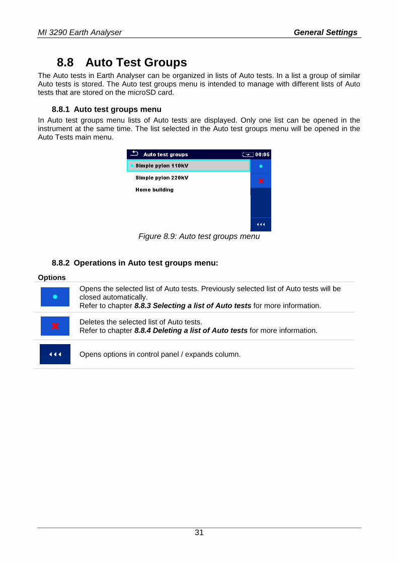
8.8 Auto Test Groups The Auto tests in Earth Analyser can be organized in lists of Auto tests. In a list a group of similar Auto tests is stored. The Auto test groups menu is intended to manage with different lists of Auto tests that are stored on the microSD card.
8.8.1 Auto test groups menu
In Auto test groups menu lists of Auto tests are displayed. Only one list can be opened in the instrument at the same time. The list selected in the Auto test groups menu will be opened in the Auto Tests main menu.
Figure 8.9: Auto test groups menu
8.8.2 Operations in Auto test groups menu:
Options
Opens the selected list of Auto tests. Previously selected list of Auto tests will be closed automatically. Refer to chapter 8.8.3 Selecting a list of Auto tests for more information.
Deletes the selected list of Auto tests. Refer to chapter 8.8.4 Deleting a list of Auto tests for more information.
Opens options in control panel / expands column.
MI 3290 Earth Analyser General Settings
32
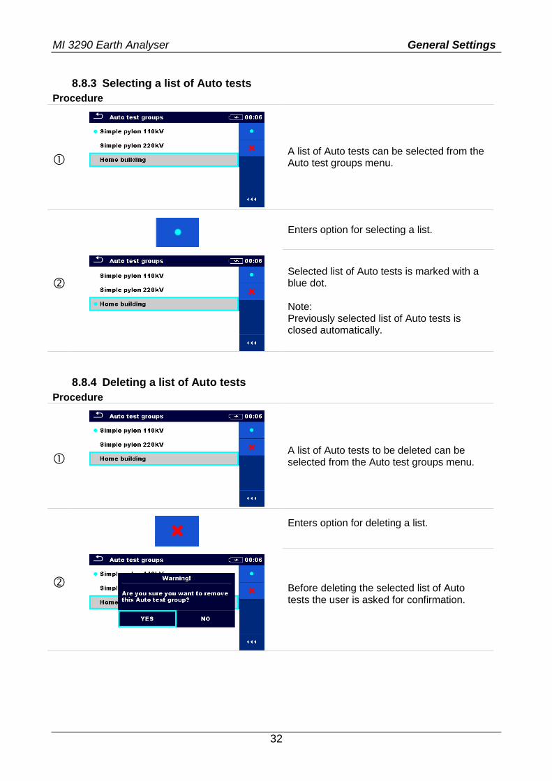
8.8.3 Selecting a list of Auto tests
Procedure
A list of Auto tests can be selected from the Auto test groups menu.
Enters option for selecting a list.
Selected list of Auto tests is marked with a blue dot. Note: Previously selected list of Auto tests is closed automatically.
8.8.4 Deleting a list of Auto tests
Procedure
A list of Auto tests to be deleted can be selected from the Auto test groups menu.
Enters option for deleting a list.
Before deleting the selected list of Auto tests the user is asked for confirmation.
MI 3290 Earth Analyser General Settings
33
A list of Auto tests is deleted.
8.9 Workspace manager The Workspace Manager is intended to manage with different Workspaces and Exports that are stored into internal data memory.
8.9.1 Workspaces and Exports
The works with MI 3290 can be organized and structured with help of Workspaces and Exports. Exports and Workspaces contain all relevant data (measurements, parameters, limits, structure objects) of an individual work. Workspaces are stored on internal data memory on directory WORKSPACES, while Exports are stored on directory EXPORTS. Export files can be read by Metrel applications that run on other devices. Exports are suitable for making backups of important works. To work on the instrument an Export should be imported first from the list of Exports and converted to a Workspace. To be stored as Export data a Workspace should be exported first from the list of Workspaces and converted to an Export.
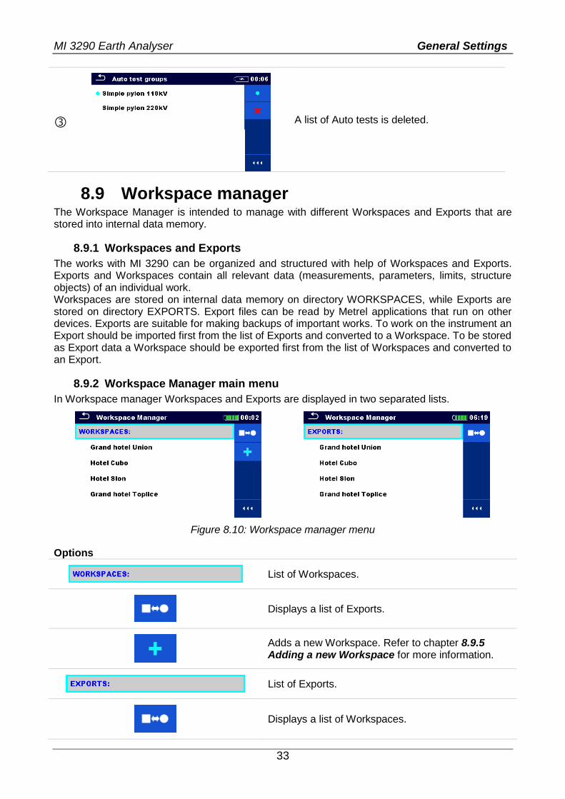
8.9.2 Workspace Manager main menu
In Workspace manager Workspaces and Exports are displayed in two separated lists.
Figure 8.10: Workspace manager menu
Options
List of Workspaces.
Displays a list of Exports.
Adds a new Workspace. Refer to chapter 8.9.5 Adding a new Workspace for more information.
List of Exports.
Displays a list of Workspaces.
MI 3290 Earth Analyser General Settings
34
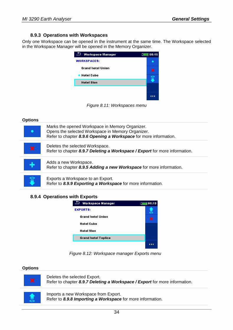
8.9.3 Operations with Workspaces
Only one Workspace can be opened in the instrument at the same time. The Workspace selected in the Workspace Manager will be opened in the Memory Organizer.
Figure 8.11: Workspaces menu
Options
Marks the opened Workspace in Memory Organizer. Opens the selected Workspace in Memory Organizer. Refer to chapter 8.9.6 Opening a Workspace for more information.
Deletes the selected Workspace. Refer to chapter 8.9.7 Deleting a Workspace / Export for more information.
Adds a new Workspace. Refer to chapter 8.9.5 Adding a new Workspace for more information.
Exports a Workspace to an Export. Refer to 8.9.9 Exporting a Workspace for more information.
8.9.4 Operations with Exports
Figure 8.12: Workspace manager Exports menu
Options
Deletes the selected Export. Refer to chapter 8.9.7 Deleting a Workspace / Export for more information.
Imports a new Workspace from Export. Refer to 8.9.8 Importing a Workspace for more information.
MI 3290 Earth Analyser General Settings
35
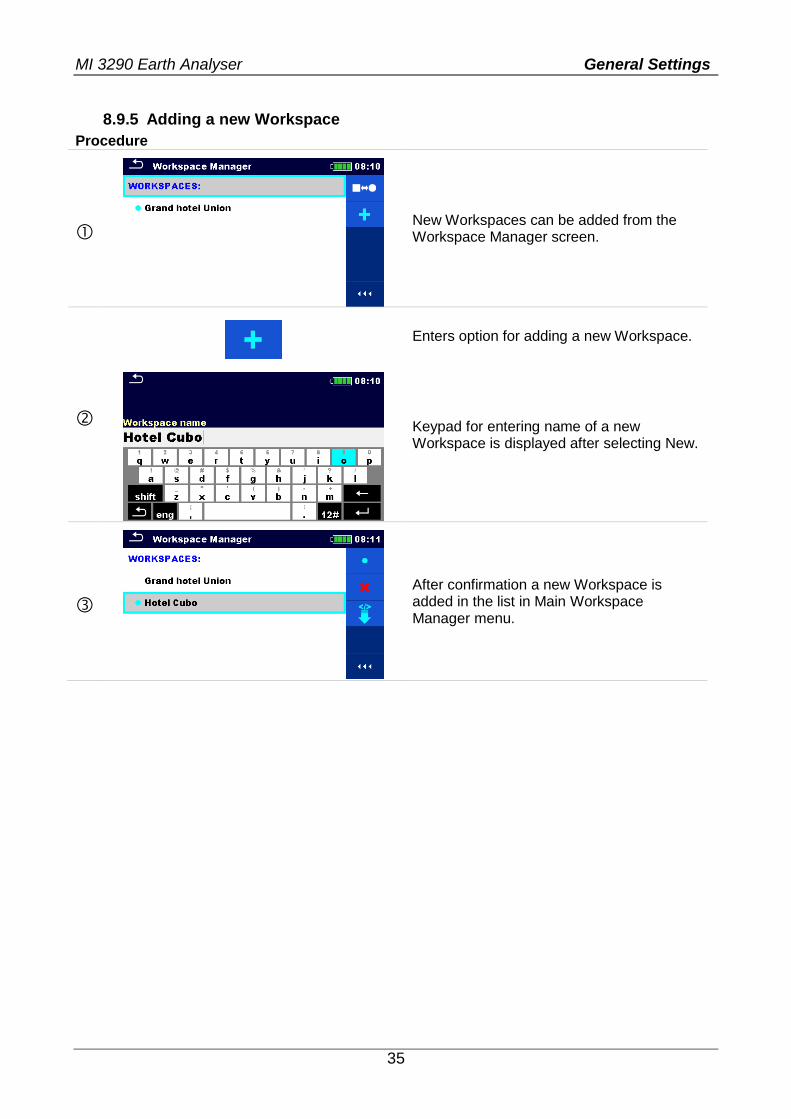
8.9.5 Adding a new Workspace
Procedure
New Workspaces can be added from the Workspace Manager screen.
Enters option for adding a new Workspace.
Keypad for entering name of a new Workspace is displayed after selecting New.
After confirmation a new Workspace is added in the list in Main Workspace Manager menu.
MI 3290 Earth Analyser General Settings
36
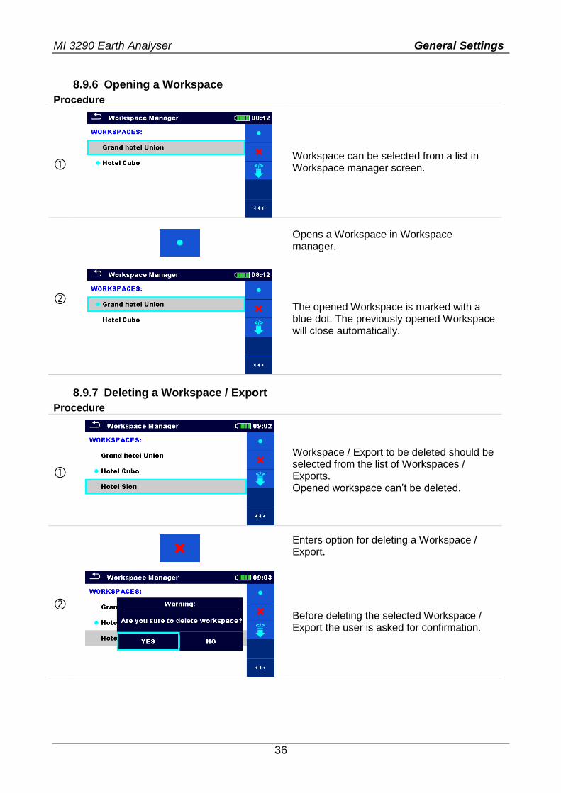
8.9.6 Opening a Workspace
Procedure
Workspace can be selected from a list in Workspace manager screen.
Opens a Workspace in Workspace manager.
The opened Workspace is marked with a blue dot. The previously opened Workspace will close automatically.
8.9.7 Deleting a Workspace / Export
Procedure
Workspace / Export to be deleted should be selected from the list of Workspaces / Exports. Opened workspace can’t be deleted.
Enters option for deleting a Workspace / Export.
Before deleting the selected Workspace / Export the user is asked for confirmation.
MI 3290 Earth Analyser General Settings
37
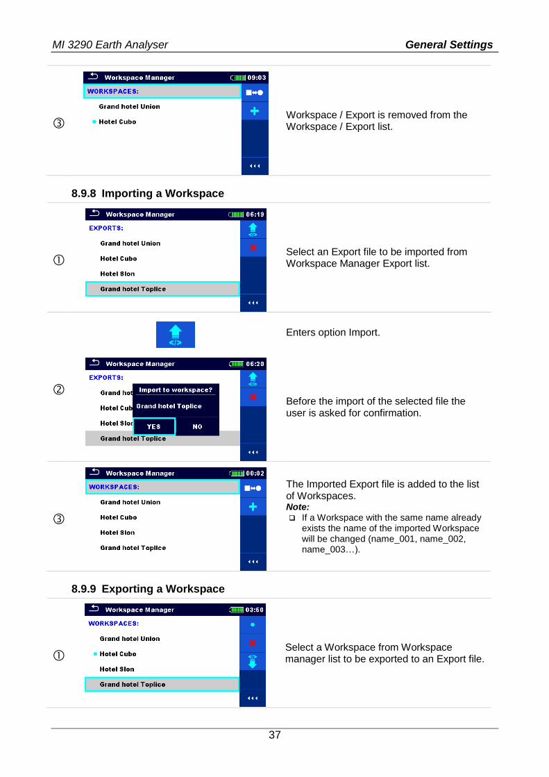
Workspace / Export is removed from the Workspace / Export list.
8.9.8 Importing a Workspace
Select an Export file to be imported from Workspace Manager Export list.
Enters option Import.
Before the import of the selected file the user is asked for confirmation.
The Imported Export file is added to the list of Workspaces. Note: If a Workspace with the same name already
exists the name of the imported Workspace will be changed (name_001, name_002, name_003…).
8.9.9 Exporting a Workspace
Select a Workspace from Workspace manager list to be exported to an Export file.
MI 3290 Earth Analyser General Settings
38
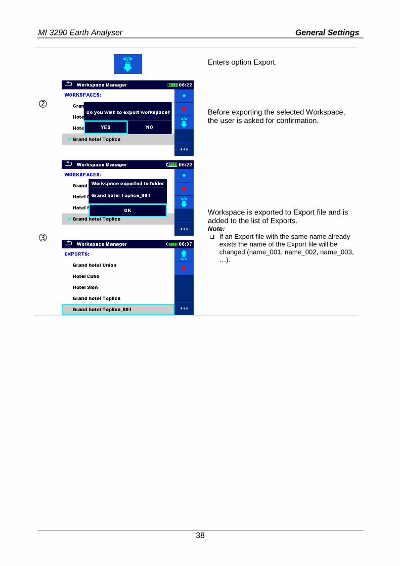
Enters option Export.
Before exporting the selected Workspace, the user is asked for confirmation.
Workspace is exported to Export file and is added to the list of Exports. Note: If an Export file with the same name already
exists the name of the Export file will be changed (name_001, name_002, name_003, …).
MI 3290 Earth Analyser Memory Organizer
39
9 Memory Organizer Memory Organizer is a tool for storing and working with test data.
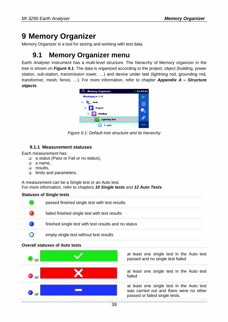
9.1 Memory Organizer menu Earth Analyser instrument has a multi-level structure. The hierarchy of Memory organizer in the
tree is shown on Figure 9.1. The data is organized according to the project, object (building, power
station, sub-station, transmission tower, …) and device under test (lightning rod, grounding rod,
transformer, mesh, fence, …). For more information, refer to chapter Appendix A – Structure
objects.
Figure 9.1: Default tree structure and its hierarchy
9.1.1 Measurement statuses
Each measurement has: a status (Pass or Fail or no status), a name, results, limits and parameters.
A measurement can be a Single test or an Auto test. For more information, refer to chapters 10 Single tests and 12 Auto Tests.
Statuses of Single tests
passed finished single test with test results
failed finished single test with test results
finished single test with test results and no status
empty single test without test results
Overall statuses of Auto tests
or
at least one single test in the Auto test passed and no single test failed
or
at least one single test in the Auto test failed
or
at least one single test in the Auto test was carried out and there were no other passed or failed single tests.
MI 3290 Earth Analyser Memory Organizer
40
or empty Auto test with empty single tests
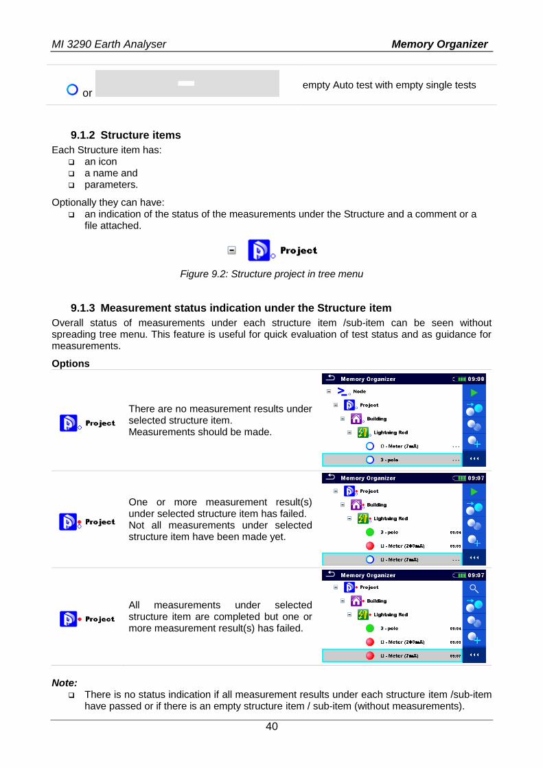
9.1.2 Structure items
Each Structure item has: an icon a name and parameters.
Optionally they can have: an indication of the status of the measurements under the Structure and a comment or a
file attached.
Figure 9.2: Structure project in tree menu
9.1.3 Measurement status indication under the Structure item
Overall status of measurements under each structure item /sub-item can be seen without spreading tree menu. This feature is useful for quick evaluation of test status and as guidance for measurements.
Options
There are no measurement results under selected structure item. Measurements should be made.
One or more measurement result(s) under selected structure item has failed. Not all measurements under selected structure item have been made yet.
All measurements under selected structure item are completed but one or more measurement result(s) has failed.
Note:
There is no status indication if all measurement results under each structure item /sub-item have passed or if there is an empty structure item / sub-item (without measurements).
MI 3290 Earth Analyser Memory Organizer
41
9.1.4 Operations in Tree menu
In the Memory organizer different actions can be taken with help of the control panel at the right side of the display. Possible actions depend on the selected element in the organizer.
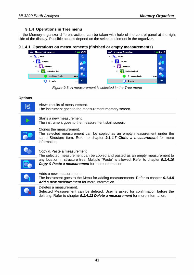
9.1.4.1 Operations on measurements (finished or empty measurements)
Figure 9.3: A measurement is selected in the Tree menu
Options
Views results of measurement. The instrument goes to the measurement memory screen.
Starts a new measurement. The instrument goes to the measurement start screen.
Clones the measurement. The selected measurement can be copied as an empty measurement under the same Structure item. Refer to chapter 9.1.4.7 Clone a measurement for more information.
Copy & Paste a measurement. The selected measurement can be copied and pasted as an empty measurement to any location in structure tree. Multiple “Paste” is allowed. Refer to chapter 9.1.4.10 Copy & Paste a measurement for more information.
Adds a new measurement. The instrument goes to the Menu for adding measurements. Refer to chapter 9.1.4.5 Add a new measurement for more information.
Deletes a measurement. Selected Measurement can be deleted. User is asked for confirmation before the deleting. Refer to chapter 9.1.4.12 Delete a measurement for more information.
MI 3290 Earth Analyser Memory Organizer
42
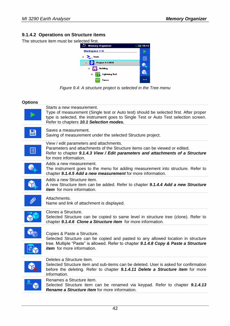
9.1.4.2 Operations on Structure items
The structure item must be selected first.
Figure 9.4: A structure project is selected in the Tree menu
Options
Starts a new measurement. Type of measurement (Single test or Auto test) should be selected first. After proper type is selected, the instrument goes to Single Test or Auto Test selection screen. Refer to chapters 10.1 Selection modes.
Saves a measurement. Saving of measurement under the selected Structure project.
View / edit parameters and attachments. Parameters and attachments of the Structure items can be viewed or edited. Refer to chapter 9.1.4.3 View / Edit parameters and attachments of a Structure for more information.
Adds a new measurement. The instrument goes to the menu for adding measurement into structure. Refer to chapter 9.1.4.5 Add a new measurement for more information.
Adds a new Structure item. A new Structure item can be added. Refer to chapter 9.1.4.4 Add a new Structure item for more information.
Attachments. Name and link of attachment is displayed.
Clones a Structure. Selected Structure can be copied to same level in structure tree (clone). Refer to chapter 9.1.4.6 Clone a Structure item for more information.
Copies & Paste a Structure. Selected Structure can be copied and pasted to any allowed location in structure tree. Multiple “Paste” is allowed. Refer to chapter 9.1.4.8 Copy & Paste a Structure item for more information.
Deletes a Structure item. Selected Structure item and sub-items can be deleted. User is asked for confirmation before the deleting. Refer to chapter 9.1.4.11 Delete a Structure item for more information.
Renames a Structure item. Selected Structure item can be renamed via keypad. Refer to chapter 9.1.4.13 Rename a Structure item for more information.
MI 3290 Earth Analyser Memory Organizer
43
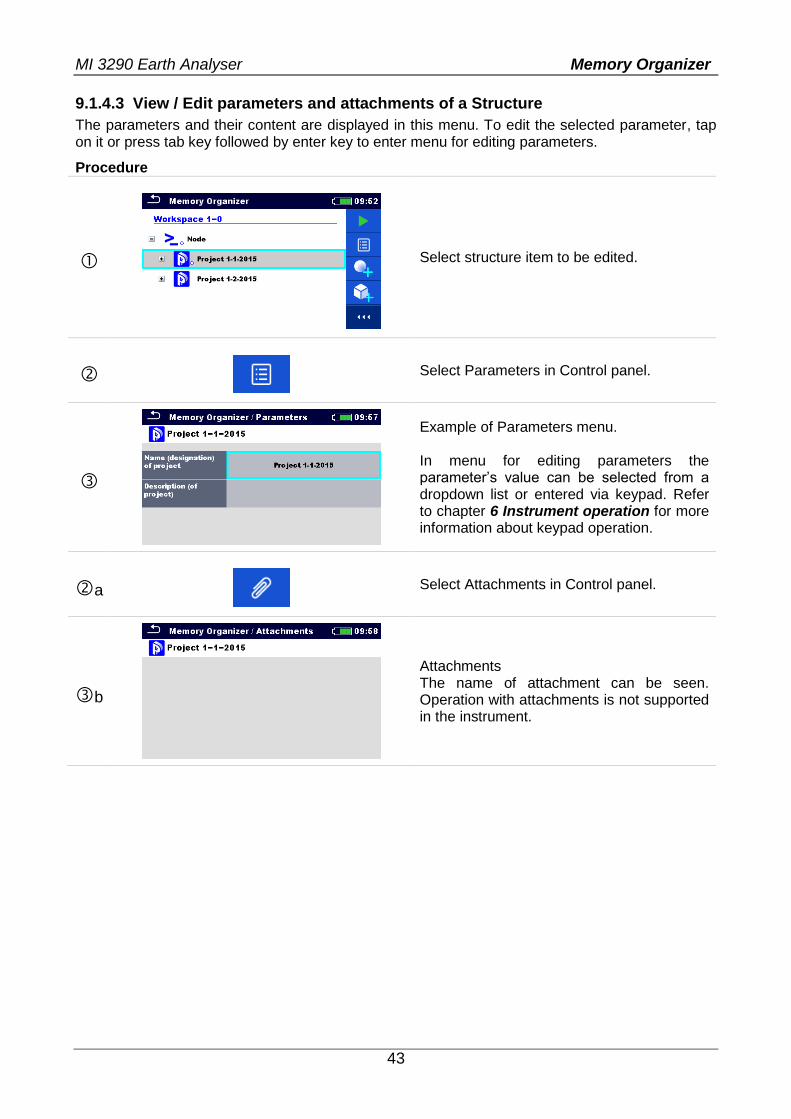
9.1.4.3 View / Edit parameters and attachments of a Structure
The parameters and their content are displayed in this menu. To edit the selected parameter, tap on it or press tab key followed by enter key to enter menu for editing parameters.
Procedure
Select structure item to be edited.
Select Parameters in Control panel.
Example of Parameters menu. In menu for editing parameters the parameter’s value can be selected from a dropdown list or entered via keypad. Refer to chapter 6 Instrument operation for more information about keypad operation.
a
Select Attachments in Control panel.
b
Attachments The name of attachment can be seen. Operation with attachments is not supported in the instrument.
MI 3290 Earth Analyser Memory Organizer
44
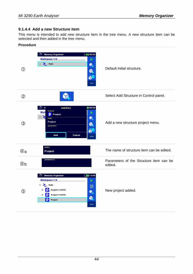
9.1.4.4 Add a new Structure item
This menu is intended to add new structure item in the tree menu. A new structure item can be selected and then added in the tree menu.
Procedure
Default initial structure.
Select Add Structure in Control panel.
Add a new structure project menu.
a The name of structure item can be edited.
b
Parameters of the Structure item can be edited.
New project added.
MI 3290 Earth Analyser Memory Organizer
45
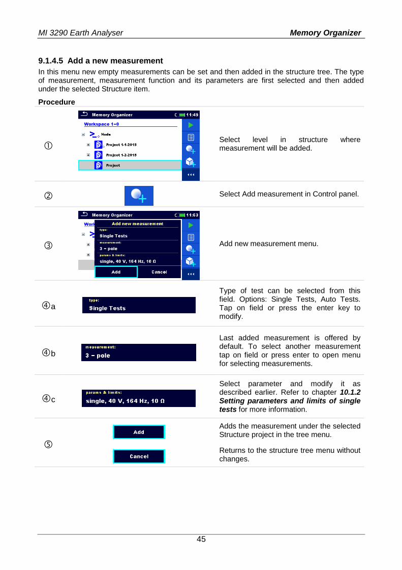
9.1.4.5 Add a new measurement
In this menu new empty measurements can be set and then added in the structure tree. The type of measurement, measurement function and its parameters are first selected and then added under the selected Structure item.
Procedure
Select level in structure where measurement will be added.
Select Add measurement in Control panel.
Add new measurement menu.
a
Type of test can be selected from this field. Options: Single Tests, Auto Tests. Tap on field or press the enter key to modify.
b
Last added measurement is offered by default. To select another measurement tap on field or press enter to open menu for selecting measurements.
c
Select parameter and modify it as described earlier. Refer to chapter 10.1.2 Setting parameters and limits of single tests for more information.
Adds the measurement under the selected Structure project in the tree menu.
Returns to the structure tree menu without changes.
MI 3290 Earth Analyser Memory Organizer
46
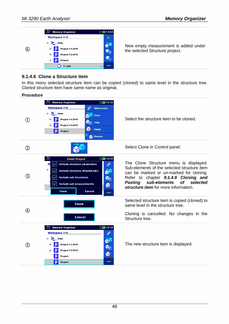
New empty measurement is added under the selected Structure project.
9.1.4.6 Clone a Structure item
In this menu selected structure item can be copied (cloned) to same level in the structure tree. Cloned structure item have same name as original.
Procedure
Select the structure item to be cloned.
Select Clone in Control panel.
The Clone Structure menu is displayed. Sub-elements of the selected structure item can be marked or un-marked for cloning. Refer to chapter 9.1.4.9 Cloning and Pasting sub-elements of selected structure item for more information.
Selected structure item is copied (cloned) to same level in the structure tree.
Cloning is cancelled. No changes in the Structure tree.
The new structure item is displayed.
MI 3290 Earth Analyser Memory Organizer
47
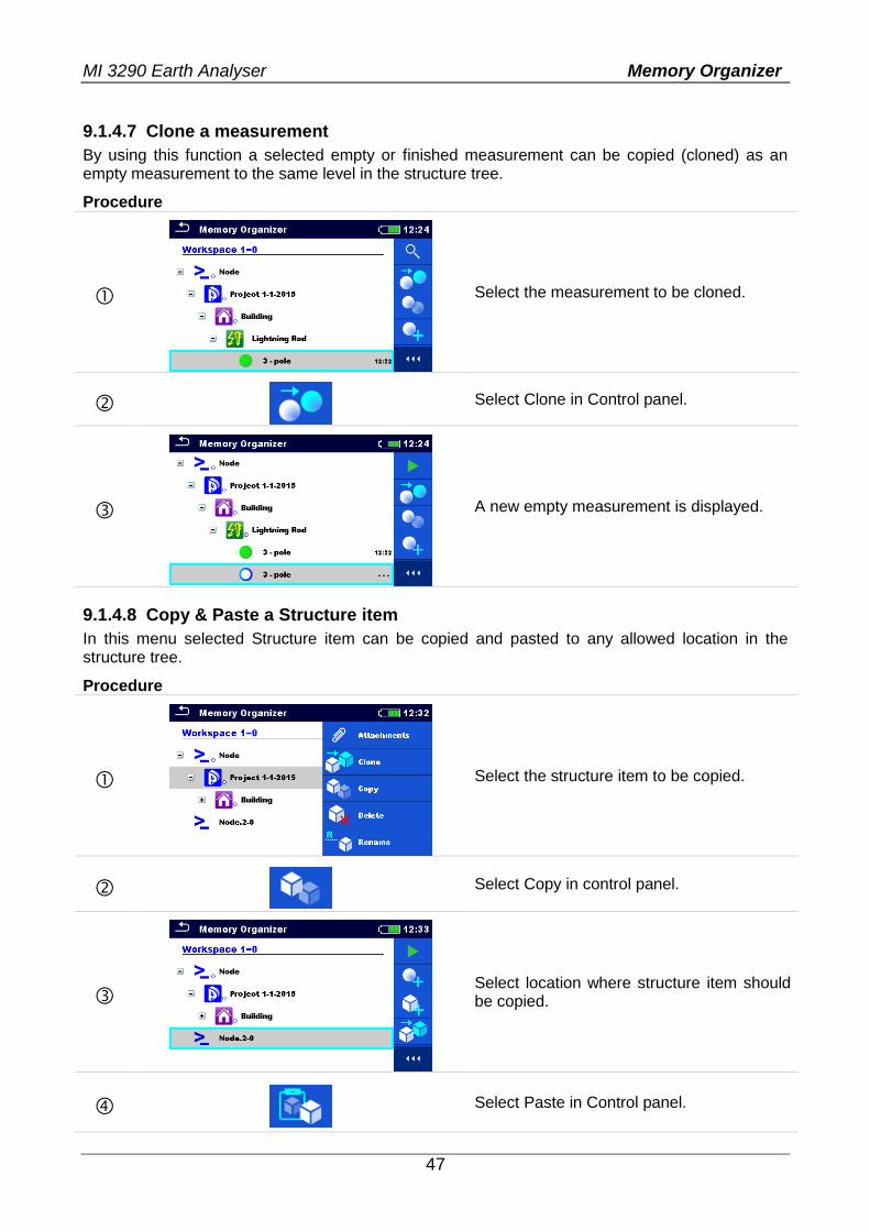
9.1.4.7 Clone a measurement
By using this function a selected empty or finished measurement can be copied (cloned) as an empty measurement to the same level in the structure tree.
Procedure
Select the measurement to be cloned.
Select Clone in Control panel.
A new empty measurement is displayed.
9.1.4.8 Copy & Paste a Structure item
In this menu selected Structure item can be copied and pasted to any allowed location in the structure tree.
Procedure
Select the structure item to be copied.
Select Copy in control panel.
Select location where structure item should be copied.
Select Paste in Control panel.
MI 3290 Earth Analyser Memory Organizer
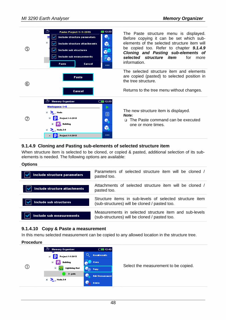
48
The Paste structure menu is displayed. Before copying it can be set which sub-elements of the selected structure item will be copied too. Refer to chapter 9.1.4.9 Cloning and Pasting sub-elements of selected structure item for more information.
The selected structure item and elements are copied (pasted) to selected position in the tree structure.
Returns to the tree menu without changes.
The new structure item is displayed. Note:
The Paste command can be executed one or more times.
9.1.4.9 Cloning and Pasting sub-elements of selected structure item
When structure item is selected to be cloned, or copied & pasted, additional selection of its sub-elements is needed. The following options are available:
Options
Parameters of selected structure item will be cloned / pasted too.
Attachments of selected structure item will be cloned / pasted too.
Structure items in sub-levels of selected structure item (sub-structures) will be cloned / pasted too.
Measurements in selected structure item and sub-levels (sub-structures) will be cloned / pasted too.
9.1.4.10 Copy & Paste a measurement
In this menu selected measurement can be copied to any allowed location in the structure tree.
Procedure
Select the measurement to be copied.
MI 3290 Earth Analyser Memory Organizer
49
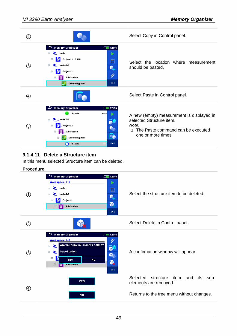
Select Copy in Control panel.
Select the location where measurement should be pasted.
Select Paste in Control panel.
A new (empty) measurement is displayed in selected Structure item. Note:
The Paste command can be executed one or more times.
9.1.4.11 Delete a Structure item
In this menu selected Structure item can be deleted.
Procedure
Select the structure item to be deleted.
Select Delete in Control panel.
A confirmation window will appear.
Selected structure item and its sub-elements are removed.
Returns to the tree menu without changes.
MI 3290 Earth Analyser Memory Organizer
50
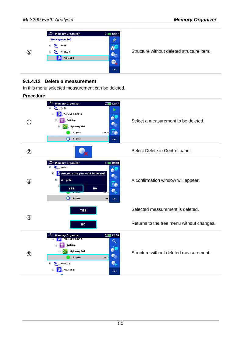
Structure without deleted structure item.
9.1.4.12 Delete a measurement
In this menu selected measurement can be deleted.
Procedure
Select a measurement to be deleted.
Select Delete in Control panel.
A confirmation window will appear.
Selected measurement is deleted.
Returns to the tree menu without changes.
Structure without deleted measurement.
MI 3290 Earth Analyser Memory Organizer
51
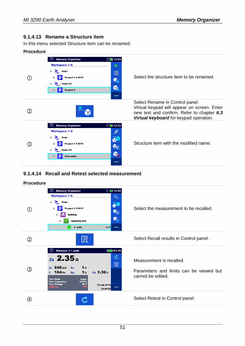
9.1.4.13 Rename a Structure item
In this menu selected Structure item can be renamed.
Procedure
Select the structure item to be renamed.
Select Rename in Control panel. Virtual keypad will appear on screen. Enter new text and confirm. Refer to chapter 6.3 Virtual keyboard for keypad operation.
Structure item with the modified name.
9.1.4.14 Recall and Retest selected measurement
Procedure
Select the measurement to be recalled.
Select Recall results in Control panel.
Measurement is recalled. Parameters and limits can be viewed but cannot be edited.
Select Retest in Control panel.
MI 3290 Earth Analyser Memory Organizer
52
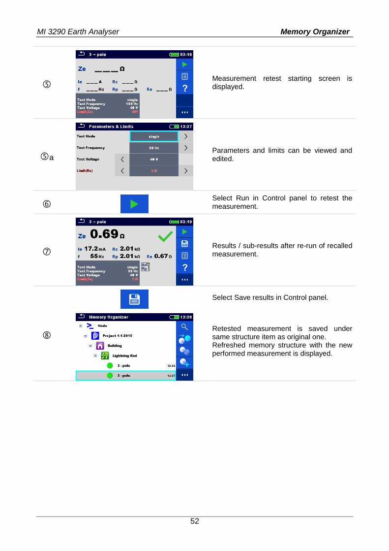
Measurement retest starting screen is displayed.
a
Parameters and limits can be viewed and edited.
Select Run in Control panel to retest the measurement.
Results / sub-results after re-run of recalled measurement.
Select Save results in Control panel.
Retested measurement is saved under same structure item as original one. Refreshed memory structure with the new performed measurement is displayed.
MI 3290 Earth Analyser Single Tests
53
10 Single tests Single measurements and tests can be selected in the main Single tests menu or in Memory organizer’s main and sub-menus.
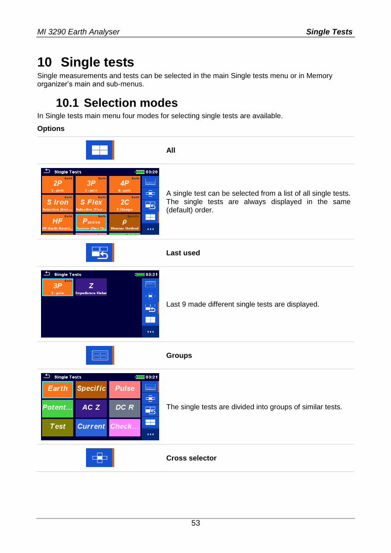
10.1 Selection modes In Single tests main menu four modes for selecting single tests are available.
Options
All
A single test can be selected from a list of all single tests. The single tests are always displayed in the same (default) order.
Last used
Last 9 made different single tests are displayed.
Groups
The single tests are divided into groups of similar tests.
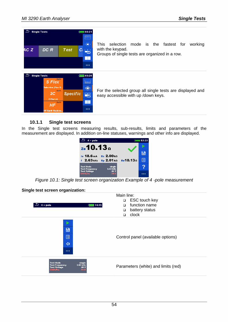
Cross selector
MI 3290 Earth Analyser Single Tests
54
This selection mode is the fastest for working with the keypad. Groups of single tests are organized in a row.
For the selected group all single tests are displayed and easy accessible with up /down keys.
10.1.1 Single test screens
In the Single test screens measuring results, sub-results, limits and parameters of the measurement are displayed. In addition on-line statuses, warnings and other info are displayed.
Figure 10.1: Single test screen organization Example of 4 -pole measurement
Single test screen organization:
Main line: ESC touch key function name battery status clock
Control panel (available options)
Parameters (white) and limits (red)
MI 3290 Earth Analyser Single Tests
55
Result field: main result(s) sub-result(s) PASS / FAIL indication number of screens
Warning symbols and message field
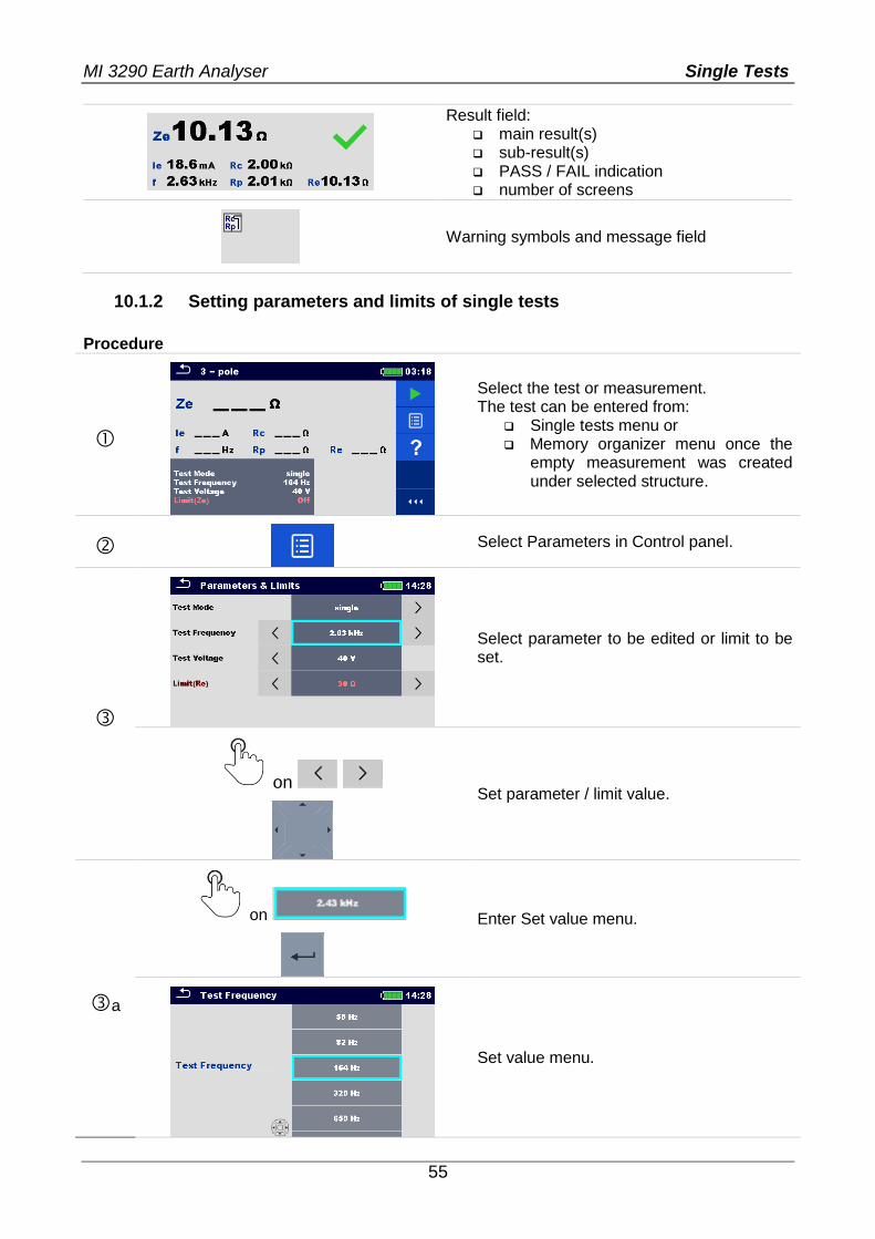
10.1.2 Setting parameters and limits of single tests
Procedure
Select the test or measurement. The test can be entered from:
Single tests menu or Memory organizer menu once the
empty measurement was created under selected structure.
Select Parameters in Control panel.
Select parameter to be edited or limit to be set.
on
Set parameter / limit value.
a
on
Enter Set value menu.
Set value menu.
MI 3290 Earth Analyser Single Tests
56
on
Accepts a new parameter or limit value and exits Set value menu.
Accepts the new parameters and limit values.
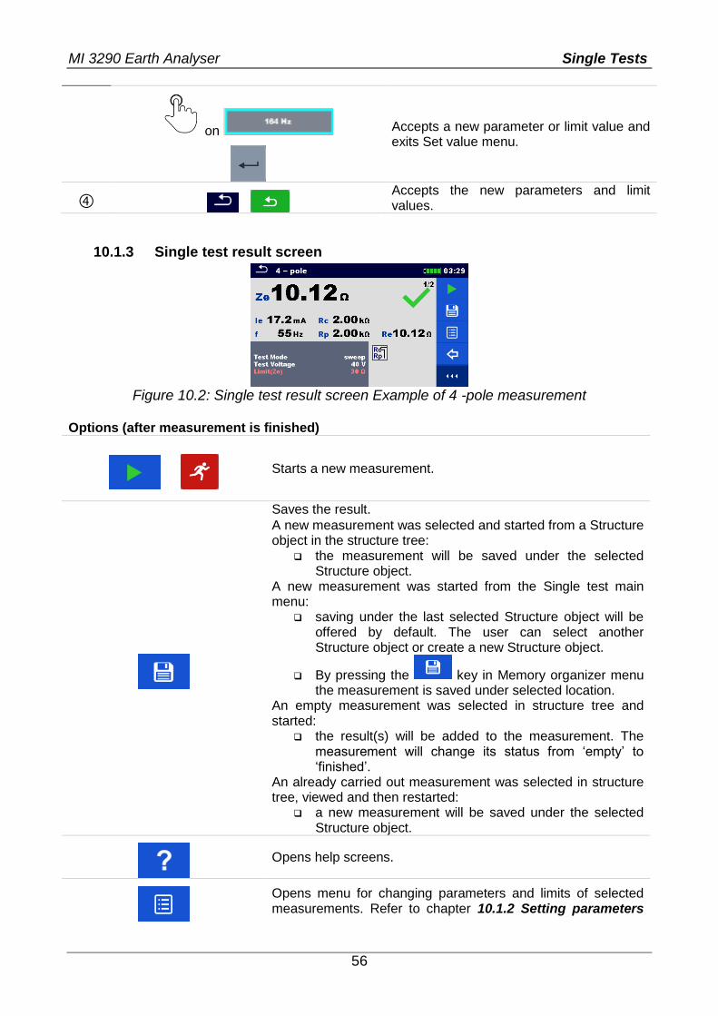
10.1.3 Single test result screen
Figure 10.2: Single test result screen Example of 4 -pole measurement
Options (after measurement is finished)
Starts a new measurement.
Saves the result.
A new measurement was selected and started from a Structure object in the structure tree:
the measurement will be saved under the selected Structure object.
A new measurement was started from the Single test main menu:
saving under the last selected Structure object will be offered by default. The user can select another Structure object or create a new Structure object.
By pressing the key in Memory organizer menu the measurement is saved under selected location.
An empty measurement was selected in structure tree and started:
the result(s) will be added to the measurement. The measurement will change its status from ‘empty’ to ‘finished’.
An already carried out measurement was selected in structure tree, viewed and then restarted:
a new measurement will be saved under the selected Structure object.
Opens help screens.
Opens menu for changing parameters and limits of selected measurements. Refer to chapter 10.1.2 Setting parameters
MI 3290 Earth Analyser Single Tests
57
on
and limits of single tests for more information how to change measurement parameters and limits.
long on
Enters cross selector to select test or measurement.
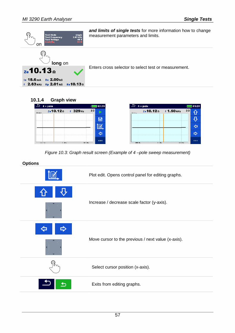
10.1.4 Graph view
Figure 10.3: Graph result screen (Example of 4 –pole sweep measurement)
Options
Plot edit. Opens control panel for editing graphs.
Increase / decrease scale factor (y-axis).
Move cursor to the previous / next value (x-axis).
Select cursor position (x-axis).
Exits from editing graphs.
MI 3290 Earth Analyser Single Tests
58
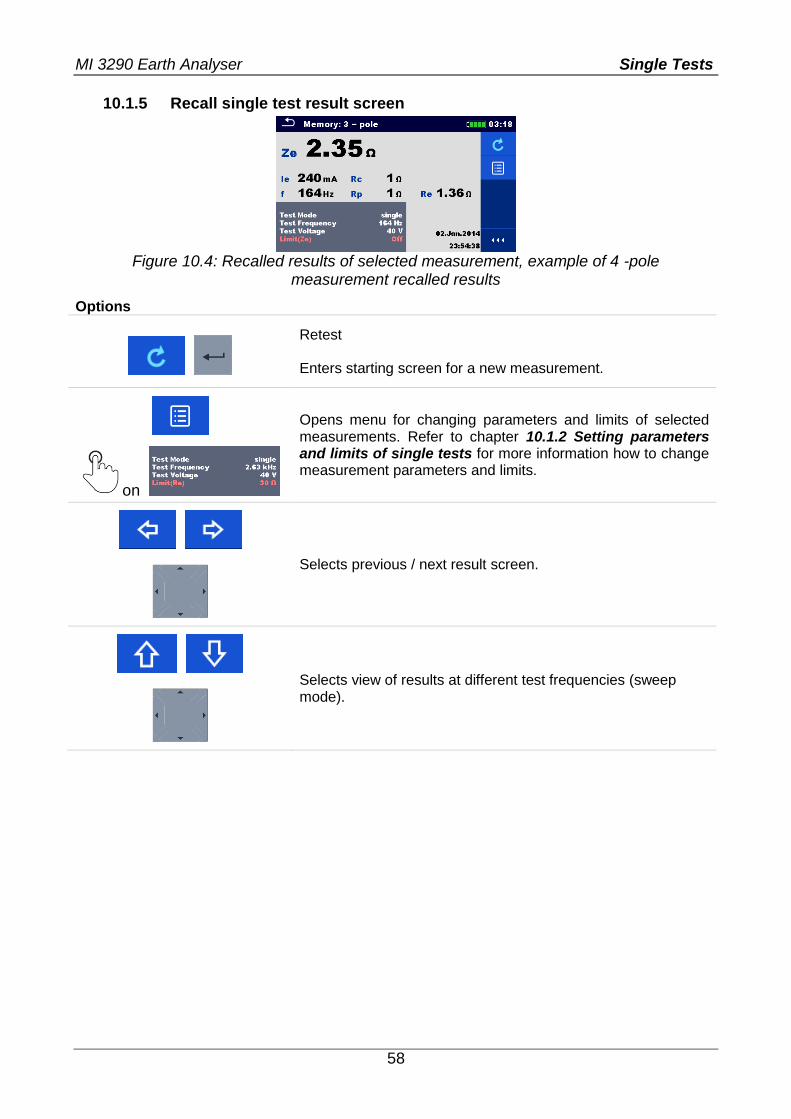
10.1.5 Recall single test result screen
Figure 10.4: Recalled results of selected measurement, example of 4 -pole
measurement recalled results
Options
Retest Enters starting screen for a new measurement.
Opens menu for changing parameters and limits of selected measurements. Refer to chapter 10.1.2 Setting parameters and limits of single tests for more information how to change measurement parameters and limits.
on
Selects previous / next result screen.
Selects view of results at different test frequencies (sweep mode).
MI 3290 Earth Analyser Tests and Measurements
59
11 Tests and Measurements
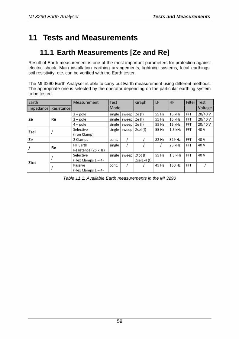
11.1 Earth Measurements [Ze and Re]
Result of Earth measurement is one of the most important parameters for protection against electric shock. Main installation earthing arrangements, lightning systems, local earthings, soil resistivity, etc. can be verified with the Earth tester.
The MI 3290 Earth Analyser is able to carry out Earth measurement using different methods. The appropriate one is selected by the operator depending on the particular earthing system to be tested.
Earth Measurement Test Mode
Graph LF HF Filter Test Voltage Impedance Resistance
Ze Re
2 – pole single sweep Ze (f) 55 Hz 15 kHz FFT 20/40 V
3 – pole single sweep Ze (f) 55 Hz 15 kHz FFT 20/40 V
4 – pole single sweep Ze (f) 55 Hz 15 kHz FFT 20/40 V
Zsel / Selective (Iron Clamp)
single sweep Zsel (f) 55 Hz 1,5 kHz FFT 40 V
Ze 2 Clamps cont. / / 82 Hz 329 Hz FFT 40 V
/ Re HF Earth Resistance (25 kHz)
single / / / 25 kHz FFT 40 V
Ztot /
Selective (Flex Clamps 1 – 4)
single sweep Ztot (f) Zsel1-4 (f)
55 Hz 1,5 kHz FFT 40 V
/ Passive (Flex Clamps 1 – 4)
cont. / / 45 Hz 150 Hz FFT /
Table 11.1: Available Earth measurements in the MI 3290
MI 3290 Earth Analyser Tests and Measurements
60
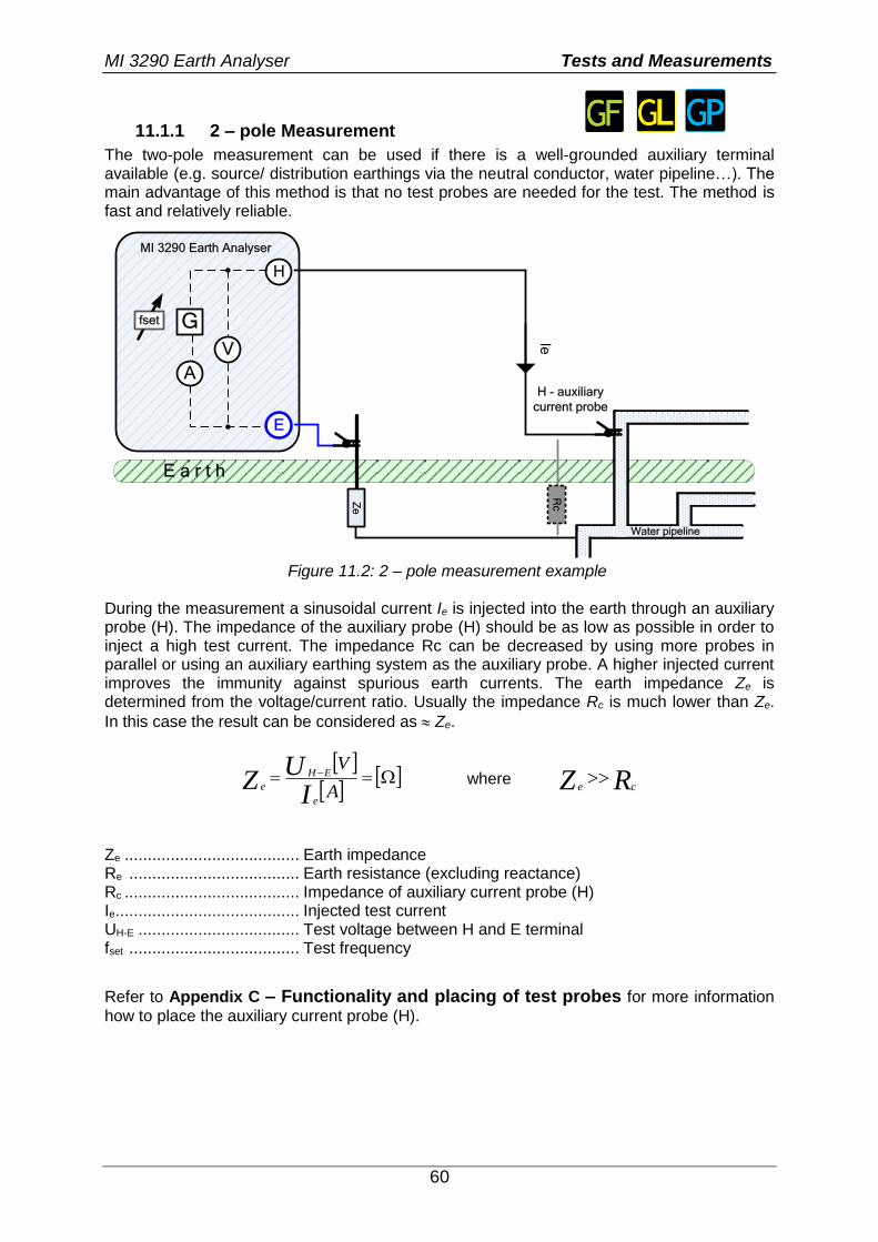
11.1.1 2 – pole Measurement
The two-pole measurement can be used if there is a well-grounded auxiliary terminal available (e.g. source/ distribution earthings via the neutral conductor, water pipeline…). The main advantage of this method is that no test probes are needed for the test. The method is fast and relatively reliable.
E a r t h
Ie
H
E
MI 3290 Earth Analyser
G
A
Ze
Water pipeline
H - auxiliary
current probe
Rc
fset
V
Figure 11.2: 2 – pole measurement example
During the measurement a sinusoidal current Ie is injected into the earth through an auxiliary probe (H). The impedance of the auxiliary probe (H) should be as low as possible in order to inject a high test current. The impedance Rc can be decreased by using more probes in parallel or using an auxiliary earthing system as the auxiliary probe. A higher injected current improves the immunity against spurious earth currents. The earth impedance Ze is determined from the voltage/current ratio. Usually the impedance Rc is much lower than Ze.
In this case the result can be considered as Ze.
A
V
IU
Ze
EH
e where RZ ce
Ze ...................................... Earth impedance Re ..................................... Earth resistance (excluding reactance) Rc ...................................... Impedance of auxiliary current probe (H) Ie ........................................ Injected test current UH-E ................................... Test voltage between H and E terminal fset ..................................... Test frequency
Refer to Appendix C – Functionality and placing of test probes for more information
how to place the auxiliary current probe (H).
MI 3290 Earth Analyser Tests and Measurements
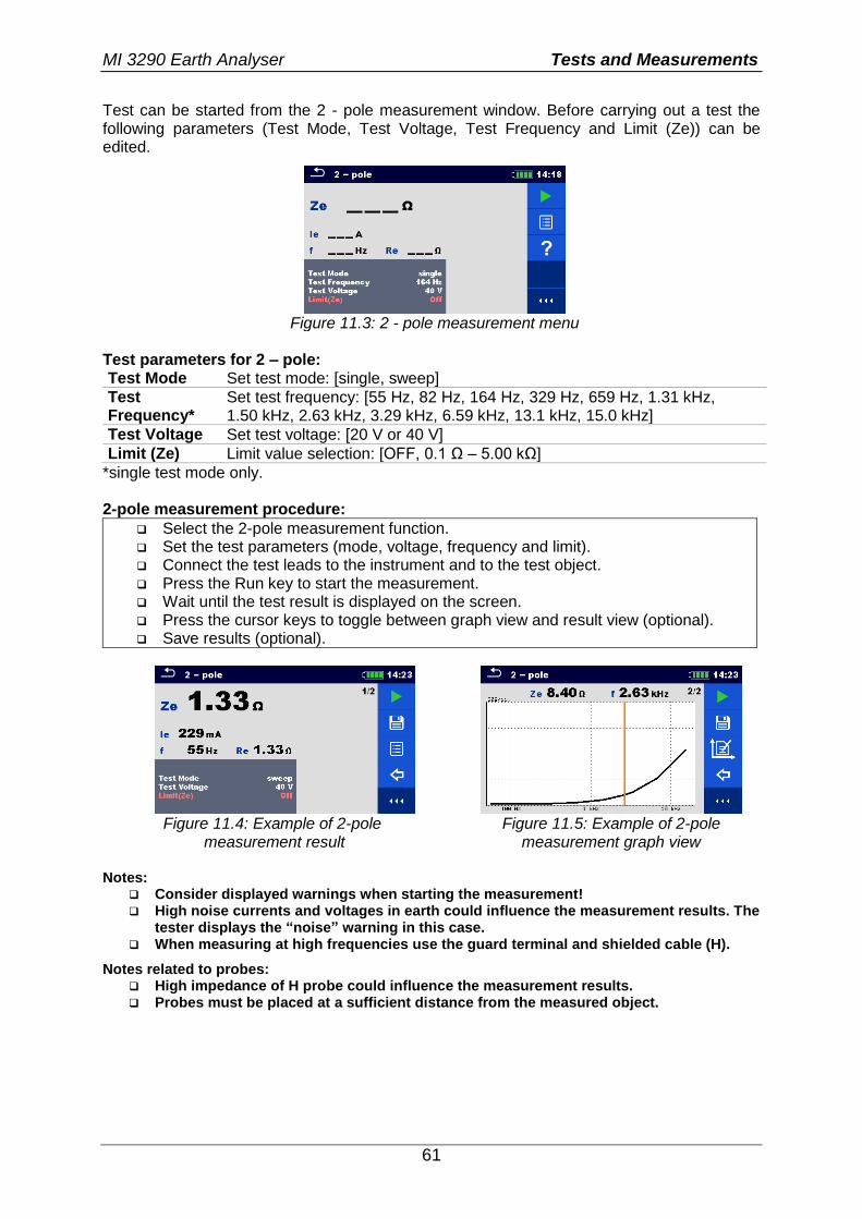
61
Test can be started from the 2 - pole measurement window. Before carrying out a test the following parameters (Test Mode, Test Voltage, Test Frequency and Limit (Ze)) can be edited.
Figure 11.3: 2 - pole measurement menu
Test parameters for 2 – pole: Test Mode Set test mode: [single, sweep]
Test Frequency*
Set test frequency: [55 Hz, 82 Hz, 164 Hz, 329 Hz, 659 Hz, 1.31 kHz, 1.50 kHz, 2.63 kHz, 3.29 kHz, 6.59 kHz, 13.1 kHz, 15.0 kHz]
Test Voltage Set test voltage: [20 V or 40 V]
Limit (Ze) Limit value selection: [OFF, 0.1 Ω – 5.00 kΩ]
*single test mode only. 2-pole measurement procedure:
Select the 2-pole measurement function. Set the test parameters (mode, voltage, frequency and limit). Connect the test leads to the instrument and to the test object. Press the Run key to start the measurement. Wait until the test result is displayed on the screen. Press the cursor keys to toggle between graph view and result view (optional). Save results (optional).
Figure 11.4: Example of 2-pole
measurement result Figure 11.5: Example of 2-pole
measurement graph view Notes:
Consider displayed warnings when starting the measurement! High noise currents and voltages in earth could influence the measurement results. The
tester displays the “noise” warning in this case. When measuring at high frequencies use the guard terminal and shielded cable (H).
Notes related to probes: High impedance of H probe could influence the measurement results. Probes must be placed at a sufficient distance from the measured object.
MI 3290 Earth Analyser Tests and Measurements
62
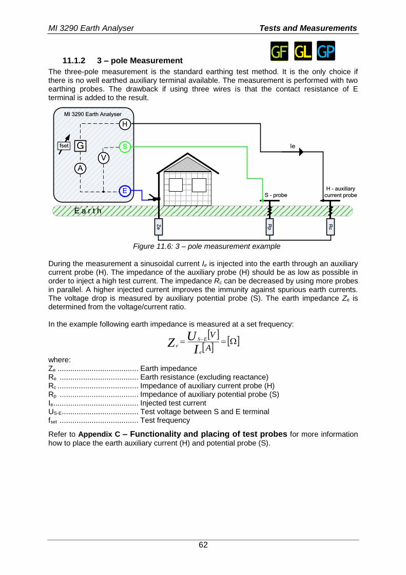
11.1.2 3 – pole Measurement
The three-pole measurement is the standard earthing test method. It is the only choice if there is no well earthed auxiliary terminal available. The measurement is performed with two earthing probes. The drawback if using three wires is that the contact resistance of E terminal is added to the result.
E a r t h
Ie
H
S
E
MI 3290 Earth Analyser
Rp
G
V
A
S - probe
H - auxiliary
current probe
Rc
Ze
fset
Figure 11.6: 3 – pole measurement example
During the measurement a sinusoidal current Ie is injected into the earth through an auxiliary current probe (H). The impedance of the auxiliary probe (H) should be as low as possible in order to inject a high test current. The impedance Rc can be decreased by using more probes in parallel. A higher injected current improves the immunity against spurious earth currents. The voltage drop is measured by auxiliary potential probe (S). The earth impedance Ze is determined from the voltage/current ratio. In the example following earth impedance is measured at a set frequency:
A
V
IU
Ze
ES
e
where: Ze ...................................... Earth impedance Re ..................................... Earth resistance (excluding reactance) Rc ...................................... Impedance of auxiliary current probe (H) Rp ..................................... Impedance of auxiliary potential probe (S) Ie ........................................ Injected test current US-E .................................... Test voltage between S and E terminal fset ..................................... Test frequency
Refer to Appendix C – Functionality and placing of test probes for more information
how to place the earth auxiliary current (H) and potential probe (S).
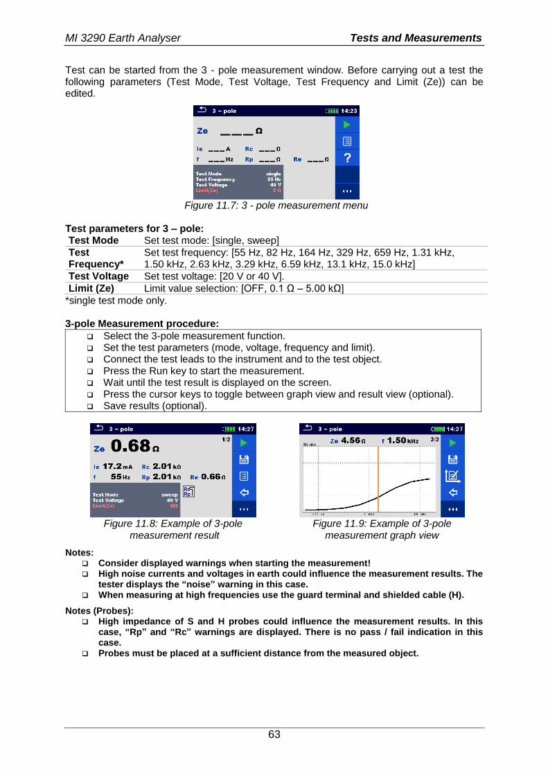
MI 3290 Earth Analyser Tests and Measurements
63
Test can be started from the 3 - pole measurement window. Before carrying out a test the following parameters (Test Mode, Test Voltage, Test Frequency and Limit (Ze)) can be edited.
Figure 11.7: 3 - pole measurement menu
Test parameters for 3 – pole: Test Mode Set test mode: [single, sweep]
Test Frequency*
Set test frequency: [55 Hz, 82 Hz, 164 Hz, 329 Hz, 659 Hz, 1.31 kHz, 1.50 kHz, 2.63 kHz, 3.29 kHz, 6.59 kHz, 13.1 kHz, 15.0 kHz]
Test Voltage Set test voltage: [20 V or 40 V].
Limit (Ze) Limit value selection: [OFF, 0.1 Ω – 5.00 kΩ]
*single test mode only. 3-pole Measurement procedure:
Select the 3-pole measurement function. Set the test parameters (mode, voltage, frequency and limit). Connect the test leads to the instrument and to the test object. Press the Run key to start the measurement. Wait until the test result is displayed on the screen. Press the cursor keys to toggle between graph view and result view (optional). Save results (optional).
Figure 11.8: Example of 3-pole
measurement result Figure 11.9: Example of 3-pole
measurement graph view
Notes: Consider displayed warnings when starting the measurement! High noise currents and voltages in earth could influence the measurement results. The
tester displays the “noise” warning in this case. When measuring at high frequencies use the guard terminal and shielded cable (H).
Notes (Probes): High impedance of S and H probes could influence the measurement results. In this
case, “Rp” and “Rc” warnings are displayed. There is no pass / fail indication in this case.
Probes must be placed at a sufficient distance from the measured object.
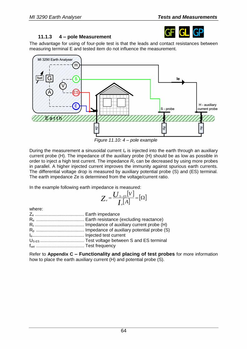
MI 3290 Earth Analyser Tests and Measurements
64
11.1.3 4 – pole Measurement
The advantage for using of four-pole test is that the leads and contact resistances between measuring terminal E and tested item do not influence the measurement.
E a r t h
H
S
ES
E
MI 3290 Earth Analyser
G
V
A
IeR
p
S - probe
H - auxiliary
current probe
Rc
Re
E a r t h
H
S
ES
E
G
V
A
IeR
p
Rc
Ze
fset
Figure 11.10: 4 – pole example
During the measurement a sinusoidal current Ie is injected into the earth through an auxiliary current probe (H). The impedance of the auxiliary probe (H) should be as low as possible in order to inject a high test current. The impedance Rc can be decreased by using more probes in parallel. A higher injected current improves the immunity against spurious earth currents. The differential voltage drop is measured by auxiliary potential probe (S) and (ES) terminal. The earth impedance Ze is determined from the voltage/current ratio. In the example following earth impedance is measured:
A
V
IU
Ze
ESS
e
where: Ze ...................................... Earth impedance Re ..................................... Earth resistance (excluding reactance) Rc ...................................... Impedance of auxiliary current probe (H) Rp ..................................... Impedance of auxiliary potential probe (S) Ie ........................................ Injected test current US-ES .................................. Test voltage between S and ES terminal fset ..................................... Test frequency
Refer to Appendix C – Functionality and placing of test probes for more information
how to place the earth auxiliary current (H) and potential probe (S).
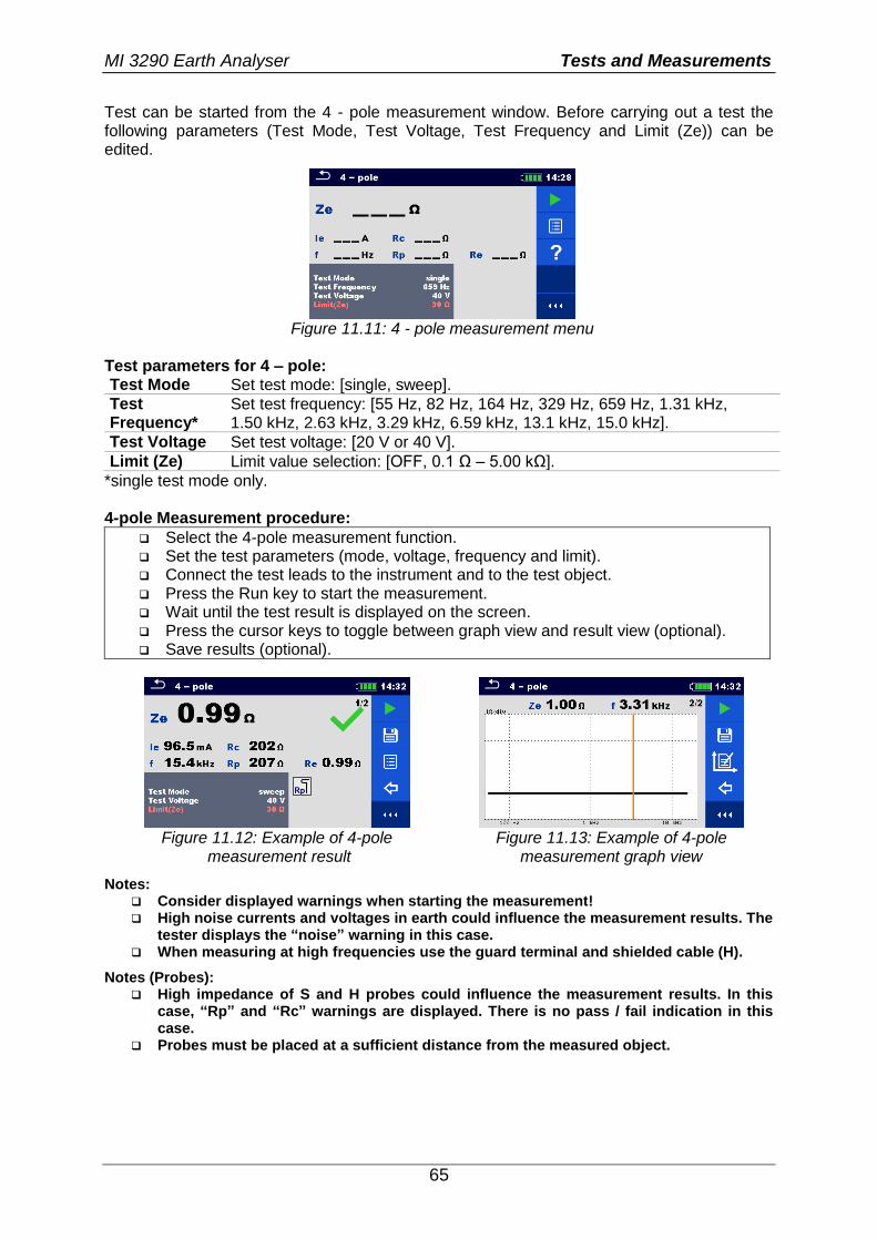
MI 3290 Earth Analyser Tests and Measurements
65
Test can be started from the 4 - pole measurement window. Before carrying out a test the following parameters (Test Mode, Test Voltage, Test Frequency and Limit (Ze)) can be edited.
Figure 11.11: 4 - pole measurement menu
Test parameters for 4 – pole: Test Mode Set test mode: [single, sweep].
Test Frequency*
Set test frequency: [55 Hz, 82 Hz, 164 Hz, 329 Hz, 659 Hz, 1.31 kHz, 1.50 kHz, 2.63 kHz, 3.29 kHz, 6.59 kHz, 13.1 kHz, 15.0 kHz].
Test Voltage Set test voltage: [20 V or 40 V].
Limit (Ze) Limit value selection: [OFF, 0.1 Ω – 5.00 kΩ].
*single test mode only. 4-pole Measurement procedure:
Select the 4-pole measurement function. Set the test parameters (mode, voltage, frequency and limit). Connect the test leads to the instrument and to the test object. Press the Run key to start the measurement. Wait until the test result is displayed on the screen. Press the cursor keys to toggle between graph view and result view (optional). Save results (optional).
Figure 11.12: Example of 4-pole
measurement result Figure 11.13: Example of 4-pole
measurement graph view
Notes: Consider displayed warnings when starting the measurement! High noise currents and voltages in earth could influence the measurement results. The
tester displays the “noise” warning in this case. When measuring at high frequencies use the guard terminal and shielded cable (H).
Notes (Probes): High impedance of S and H probes could influence the measurement results. In this
case, “Rp” and “Rc” warnings are displayed. There is no pass / fail indication in this case.
Probes must be placed at a sufficient distance from the measured object.
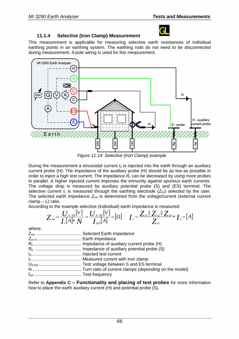
MI 3290 Earth Analyser Tests and Measurements
66
11.1.4 Selective (Iron Clamp) Measurement
This measurement is applicable for measuring selective earth resistances of individual earthing points in an earthing system. The earthing rods do not need to be disconnected during measurement. 4-pole wiring is used for this measurement.
E a r t h
Ie
S
ES
E
MI 3290 Earth AnalyserR
p
G V
A
S - probe
H - auxiliary
current probe
Rc
AC
C
Ze
2
Ze
1
Ic
Ze
3
fset
H
Figure 11.14: Selective (Iron Clamp) example
During the measurement a sinusoidal current Ie is injected into the earth through an auxiliary current probe (H). The impedance of the auxiliary probe (H) should be as low as possible in order to inject a high test current. The impedance Rc can be decreased by using more probes in parallel. A higher injected current improves the immunity against spurious earth currents. The voltage drop is measured by auxiliary potential probe (S) and (ES) terminal. The selective current Ic is measured through the earthing electrode (Ze1) selected by the user. The selected earth impedance Zsel is determined from the voltage/current (external current clamp – Ic) ratio. According to the example selective (individual) earth impedance is measured:
A
V
A
V
IU
NIU
ZZe
ESS
c
ESS
sel
1
AIZ
ZZZI e
e
eee
c
1
321||||
where: Zsel .................................... Selected Earth impedance Ze1-3 ................................... Earth impedance Rc ...................................... Impedance of auxiliary current probe (H) Rp ..................................... Impedance of auxiliary potential probe (S) Ie ........................................ Injected test current Ic ........................................ Measured current with Iron clamp US-ES .................................. Test voltage between S and ES terminal N ....................................... Turn ratio of current clamps (depending on the model) fset ..................................... Test frequency
Refer to Appendix C – Functionality and placing of test probes for more information
how to place the earth auxiliary current (H) and potential probe (S).
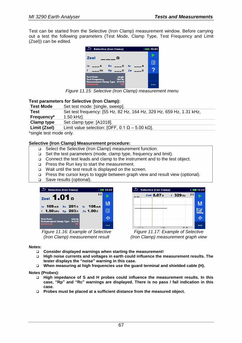
MI 3290 Earth Analyser Tests and Measurements
67
Test can be started from the Selective (Iron Clamp) measurement window. Before carrying out a test the following parameters (Test Mode, Clamp Type, Test Frequency and Limit (Zsel)) can be edited.
Figure 11.15: Selective (Iron Clamp) measurement menu
Test parameters for Selective (Iron Clamp): Test Mode Set test mode: [single, sweep].
Test Frequency*
Set test frequency: [55 Hz, 82 Hz, 164 Hz, 329 Hz, 659 Hz, 1.31 kHz, 1.50 kHz].
Clamp type Set clamp type: [A1018].
Limit (Zsel) Limit value selection: [OFF, 0.1 Ω – 5.00 kΩ].
*single test mode only. Selective (Iron Clamp) Measurement procedure:
Select the Selective (Iron Clamp) measurement function. Set the test parameters (mode, clamp type, frequency and limit). Connect the test leads and clamp to the instrument and to the test object. Press the Run key to start the measurement. Wait until the test result is displayed on the screen. Press the cursor keys to toggle between graph view and result view (optional). Save results (optional).
Figure 11.16: Example of Selective (Iron Clamp) measurement result
Figure 11.17: Example of Selective (Iron Clamp) measurement graph view
Notes:
Consider displayed warnings when starting the measurement! High noise currents and voltages in earth could influence the measurement results. The
tester displays the “noise” warning in this case. When measuring at high frequencies use the guard terminal and shielded cable (H).
Notes (Probes): High impedance of S and H probes could influence the measurement results. In this
case, “Rp” and “Rc” warnings are displayed. There is no pass / fail indication in this case.
Probes must be placed at a sufficient distance from the measured object.
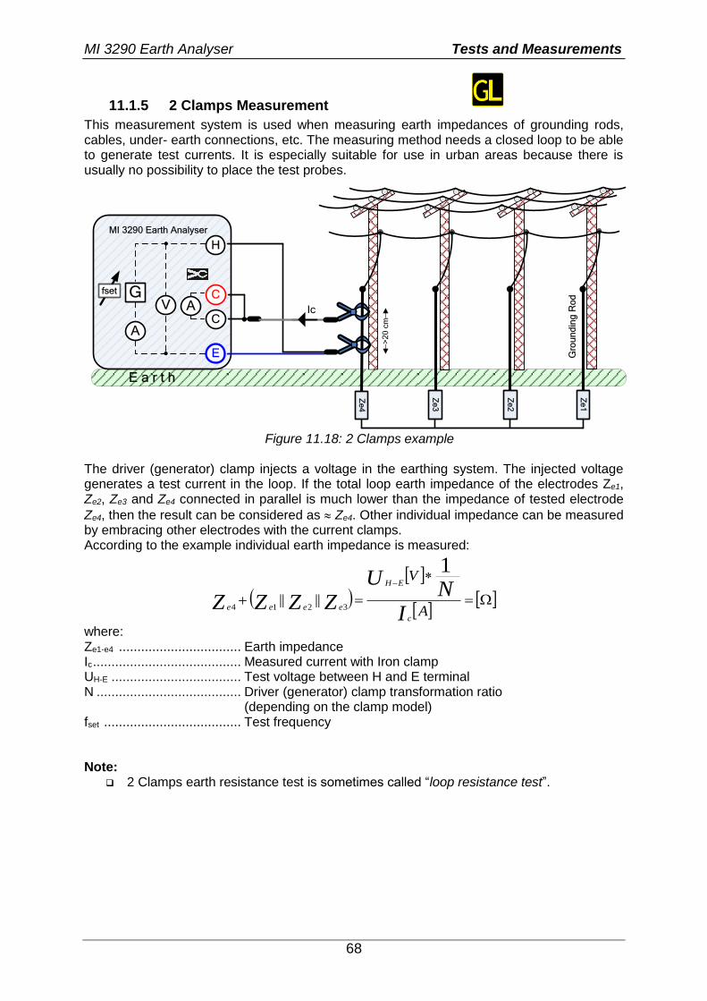
MI 3290 Earth Analyser Tests and Measurements
68
11.1.5 2 Clamps Measurement
This measurement system is used when measuring earth impedances of grounding rods, cables, under- earth connections, etc. The measuring method needs a closed loop to be able to generate test currents. It is especially suitable for use in urban areas because there is usually no possibility to place the test probes.
E a r t h
H
E
MI 3290 Earth Analyser
Ze
4
GV
A
AC
C
Ze
3
Ze
2
Ze
1
Ic
>2
0 c
m
Gro
un
din
g R
od
fset
Figure 11.18: 2 Clamps example
The driver (generator) clamp injects a voltage in the earthing system. The injected voltage generates a test current in the loop. If the total loop earth impedance of the electrodes Ze1, Ze2, Ze3 and Ze4 connected in parallel is much lower than the impedance of tested electrode
Ze4, then the result can be considered as Ze4. Other individual impedance can be measured by embracing other electrodes with the current clamps. According to the example individual earth impedance is measured:
A
V
IN
UZZZZ
c
EH
eeee
1
3214||||
where: Ze1-e4 ................................. Earth impedance Ic ........................................ Measured current with Iron clamp UH-E ................................... Test voltage between H and E terminal N ....................................... Driver (generator) clamp transformation ratio (depending on the clamp model) fset ..................................... Test frequency Note:
2 Clamps earth resistance test is sometimes called “loop resistance test”.
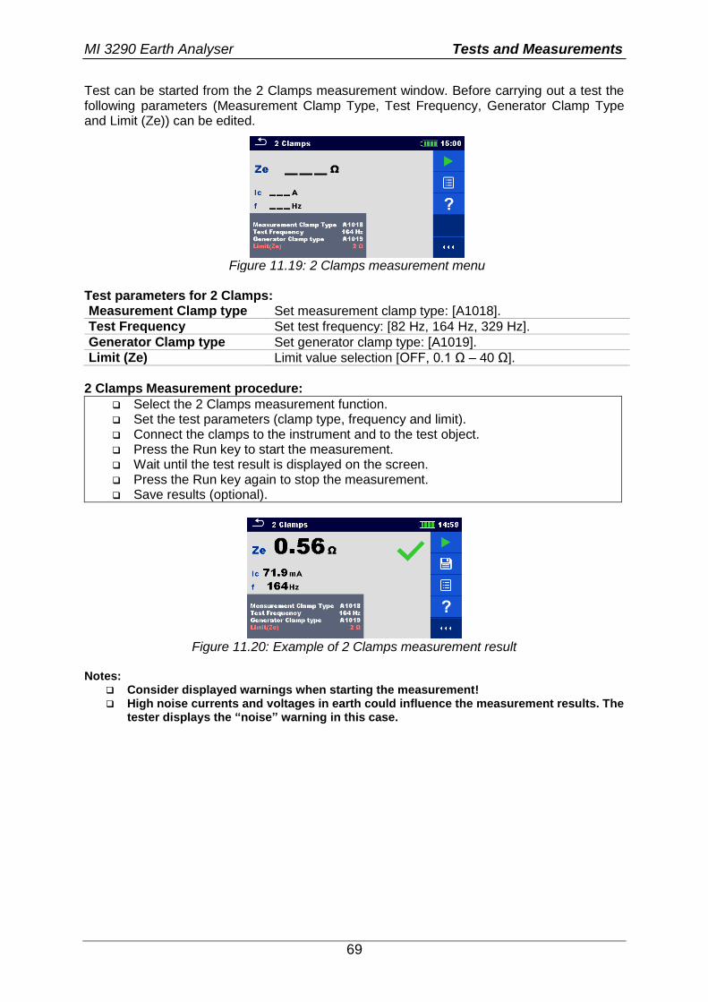
MI 3290 Earth Analyser Tests and Measurements
69
Test can be started from the 2 Clamps measurement window. Before carrying out a test the following parameters (Measurement Clamp Type, Test Frequency, Generator Clamp Type and Limit (Ze)) can be edited.
Figure 11.19: 2 Clamps measurement menu
Test parameters for 2 Clamps: Measurement Clamp type Set measurement clamp type: [A1018].
Test Frequency Set test frequency: [82 Hz, 164 Hz, 329 Hz].
Generator Clamp type Set generator clamp type: [A1019].
Limit (Ze) Limit value selection [OFF, 0.1 Ω – 40 Ω].
2 Clamps Measurement procedure:
Select the 2 Clamps measurement function. Set the test parameters (clamp type, frequency and limit). Connect the clamps to the instrument and to the test object. Press the Run key to start the measurement. Wait until the test result is displayed on the screen. Press the Run key again to stop the measurement. Save results (optional).
Figure 11.20: Example of 2 Clamps measurement result
Notes:
Consider displayed warnings when starting the measurement! High noise currents and voltages in earth could influence the measurement results. The
tester displays the “noise” warning in this case.
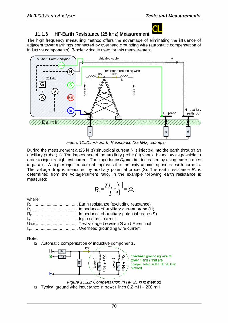
MI 3290 Earth Analyser Tests and Measurements
70
11.1.6 HF-Earth Resistance (25 kHz) Measurement
The high frequency measuring method offers the advantage of eliminating the influence of adjacent tower earthings connected by overhead grounding wire (automatic compensation of inductive components). 3-pole wiring is used for this measurement.
E a r t h
H
S
ES
E
MI 3290 Earth Analyser
Guard
Rp
G
V
A
S - probeH - auxiliary
earth rod
Rc
Ie
25 kHz
shielded cable
tower
ne
x t
ow
er
overhead grounding wireIgw
Re
Igw
L
ne
x t
ow
er
L
Figure 11.21: HF-Earth Resistance (25 kHz) example
During the measurement a (25 kHz) sinusoidal current Ie is injected into the earth through an auxiliary probe (H). The impedance of the auxiliary probe (H) should be as low as possible in order to inject a high test current. The impedance Rc can be decreased by using more probes in parallel. A higher injected current improves the immunity against spurious earth currents. The voltage drop is measured by auxiliary potential probe (S). The earth resistance Re is determined from the voltage/current ratio. In the example following earth resistance is measured:
A
V
IU
Re
ES
e
where: Re ..................................... Earth resistance (excluding reactance) Rc ...................................... Impedance of auxiliary current probe (H) Rp ..................................... Impedance of auxiliary potential probe (S) Ie ........................................ Injected test current US-E .................................... Test voltage between S and E terminal Igw ...................................... Overhead grounding wire current
Note: Automatic compensation of inductive components.
tow
er
1
Re
XL
1 + R
L1
RL
Igw
Rp
RcH
S
E
Overhead grounding wire of
tower 1 and 2 that are
compensated in the HF 25 kHz
method.
XL
2 + R
L2
RL
tow
er
2
Figure 11.22: Compensation in HF 25 kHz method
Typical ground wire inductance in power lines 0.2 mH – 200 mH.
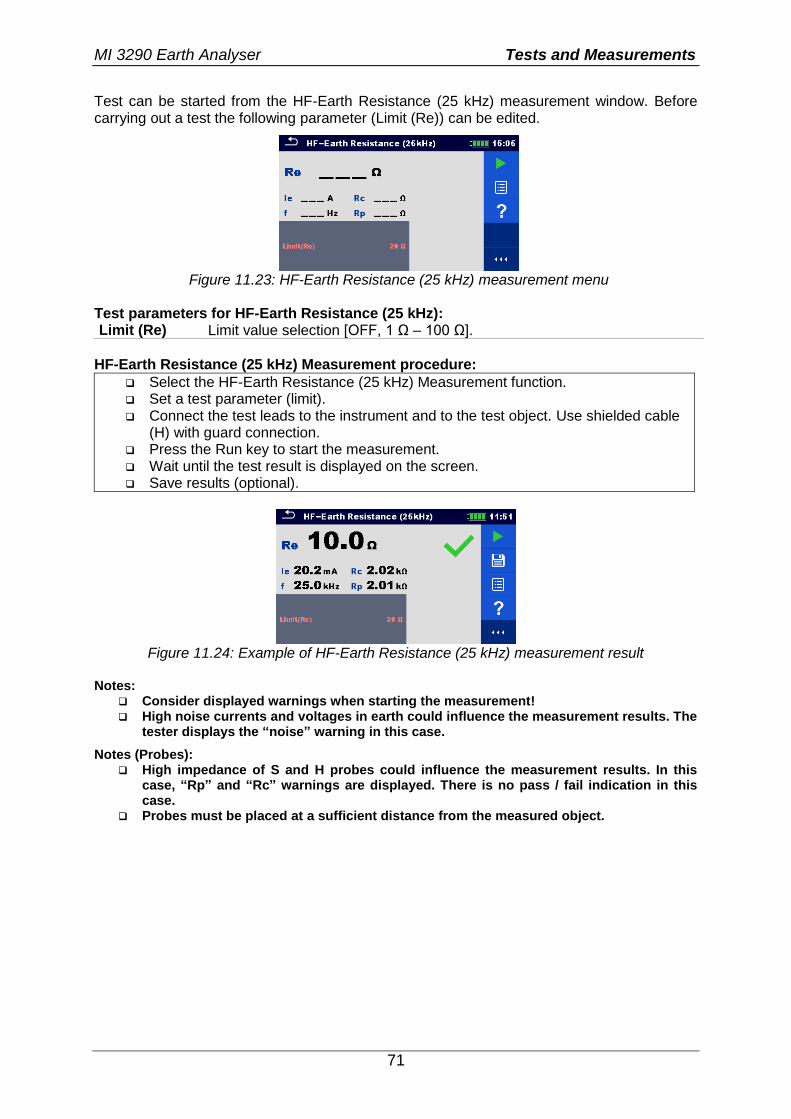
MI 3290 Earth Analyser Tests and Measurements
71
Test can be started from the HF-Earth Resistance (25 kHz) measurement window. Before carrying out a test the following parameter (Limit (Re)) can be edited.
Figure 11.23: HF-Earth Resistance (25 kHz) measurement menu
Test parameters for HF-Earth Resistance (25 kHz): Limit (Re) Limit value selection [OFF, 1 Ω – 100 Ω].
HF-Earth Resistance (25 kHz) Measurement procedure:
Select the HF-Earth Resistance (25 kHz) Measurement function. Set a test parameter (limit). Connect the test leads to the instrument and to the test object. Use shielded cable
(H) with guard connection. Press the Run key to start the measurement. Wait until the test result is displayed on the screen. Save results (optional).
Figure 11.24: Example of HF-Earth Resistance (25 kHz) measurement result
Notes:
Consider displayed warnings when starting the measurement! High noise currents and voltages in earth could influence the measurement results. The
tester displays the “noise” warning in this case.
Notes (Probes): High impedance of S and H probes could influence the measurement results. In this
case, “Rp” and “Rc” warnings are displayed. There is no pass / fail indication in this case.
Probes must be placed at a sufficient distance from the measured object.
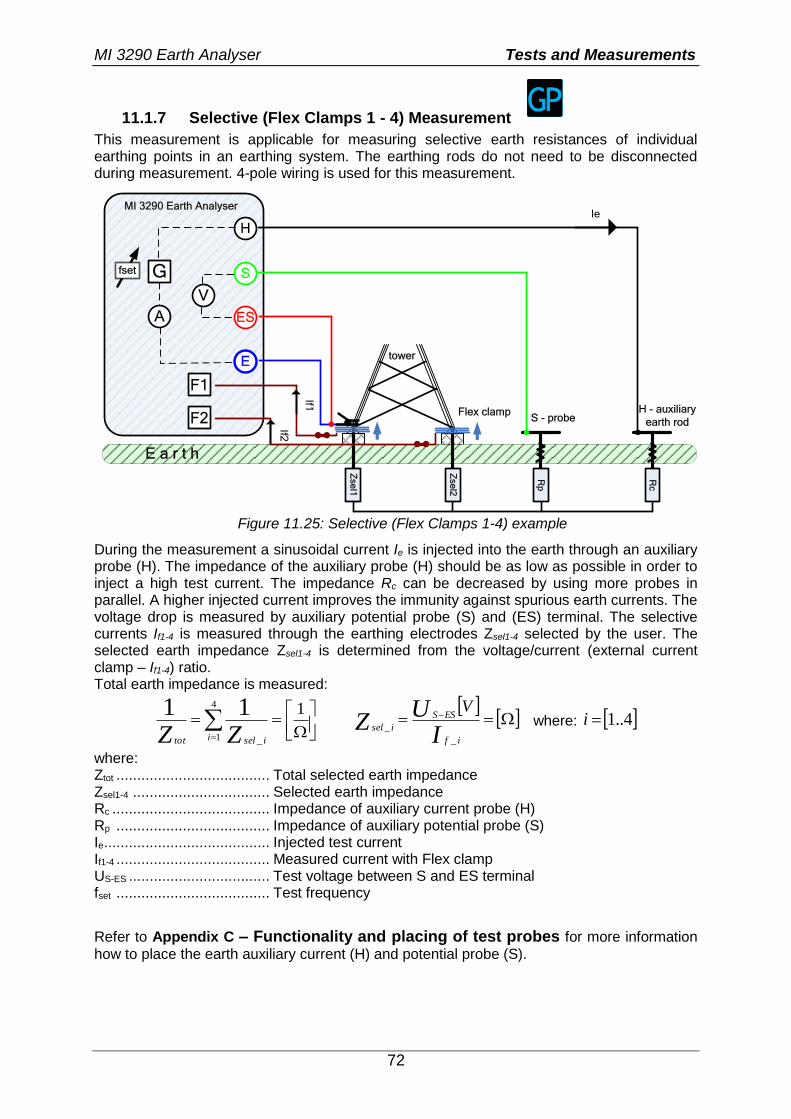
MI 3290 Earth Analyser Tests and Measurements
72
11.1.7 Selective (Flex Clamps 1 - 4) Measurement
This measurement is applicable for measuring selective earth resistances of individual earthing points in an earthing system. The earthing rods do not need to be disconnected during measurement. 4-pole wiring is used for this measurement.
E a r t h
H
S
ES
E
MI 3290 Earth Analyser
Zse
l1
Rp
G
V
A
S - probeH - auxiliary
earth rod
Rc
Ie
tower
Zse
l2
F2
F1
Flex clamp
If1
If2
fset
Figure 11.25: Selective (Flex Clamps 1-4) example
During the measurement a sinusoidal current Ie is injected into the earth through an auxiliary probe (H). The impedance of the auxiliary probe (H) should be as low as possible in order to inject a high test current. The impedance Rc can be decreased by using more probes in parallel. A higher injected current improves the immunity against spurious earth currents. The voltage drop is measured by auxiliary potential probe (S) and (ES) terminal. The selective currents If1-4 is measured through the earthing electrodes Zsel1-4 selected by the user. The selected earth impedance Zsel1-4 is determined from the voltage/current (external current clamp – If1-4) ratio. Total earth impedance is measured:
14
1 _
11i iseltot ZZ
IU
Zif
ESS
isel
V
_
_ where: 4..1i
where: Ztot ..................................... Total selected earth impedance Zsel1-4 ................................. Selected earth impedance Rc ...................................... Impedance of auxiliary current probe (H) Rp ..................................... Impedance of auxiliary potential probe (S) Ie ........................................ Injected test current If1-4 ..................................... Measured current with Flex clamp US-ES .................................. Test voltage between S and ES terminal fset ..................................... Test frequency
Refer to Appendix C – Functionality and placing of test probes for more information
how to place the earth auxiliary current (H) and potential probe (S).
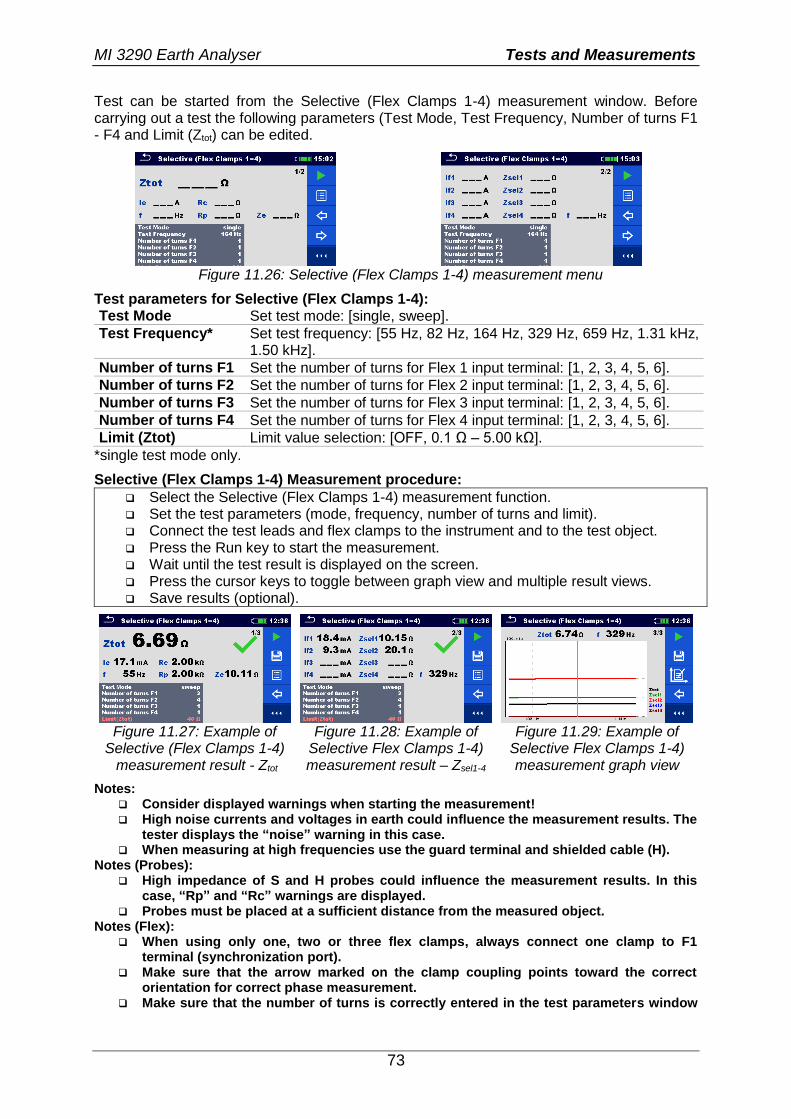
MI 3290 Earth Analyser Tests and Measurements
73
Test can be started from the Selective (Flex Clamps 1-4) measurement window. Before carrying out a test the following parameters (Test Mode, Test Frequency, Number of turns F1 - F4 and Limit (Ztot) can be edited.
Figure 11.26: Selective (Flex Clamps 1-4) measurement menu
Test parameters for Selective (Flex Clamps 1-4): Test Mode Set test mode: [single, sweep].
Test Frequency* Set test frequency: [55 Hz, 82 Hz, 164 Hz, 329 Hz, 659 Hz, 1.31 kHz, 1.50 kHz].
Number of turns F1 Set the number of turns for Flex 1 input terminal: [1, 2, 3, 4, 5, 6].
Number of turns F2 Set the number of turns for Flex 2 input terminal: [1, 2, 3, 4, 5, 6].
Number of turns F3 Set the number of turns for Flex 3 input terminal: [1, 2, 3, 4, 5, 6].
Number of turns F4 Set the number of turns for Flex 4 input terminal: [1, 2, 3, 4, 5, 6].
Limit (Ztot) Limit value selection: [OFF, 0.1 Ω – 5.00 kΩ].
*single test mode only.
Selective (Flex Clamps 1-4) Measurement procedure:
Select the Selective (Flex Clamps 1-4) measurement function. Set the test parameters (mode, frequency, number of turns and limit). Connect the test leads and flex clamps to the instrument and to the test object. Press the Run key to start the measurement. Wait until the test result is displayed on the screen. Press the cursor keys to toggle between graph view and multiple result views. Save results (optional).
Figure 11.27: Example of
Selective (Flex Clamps 1-4) measurement result - Ztot
Figure 11.28: Example of Selective Flex Clamps 1-4) measurement result – Zsel1-4
Figure 11.29: Example of Selective Flex Clamps 1-4) measurement graph view
Notes: Consider displayed warnings when starting the measurement! High noise currents and voltages in earth could influence the measurement results. The
tester displays the “noise” warning in this case. When measuring at high frequencies use the guard terminal and shielded cable (H).
Notes (Probes): High impedance of S and H probes could influence the measurement results. In this
case, “Rp” and “Rc” warnings are displayed. Probes must be placed at a sufficient distance from the measured object.
Notes (Flex): When using only one, two or three flex clamps, always connect one clamp to F1
terminal (synchronization port). Make sure that the arrow marked on the clamp coupling points toward the correct
orientation for correct phase measurement. Make sure that the number of turns is correctly entered in the test parameters window
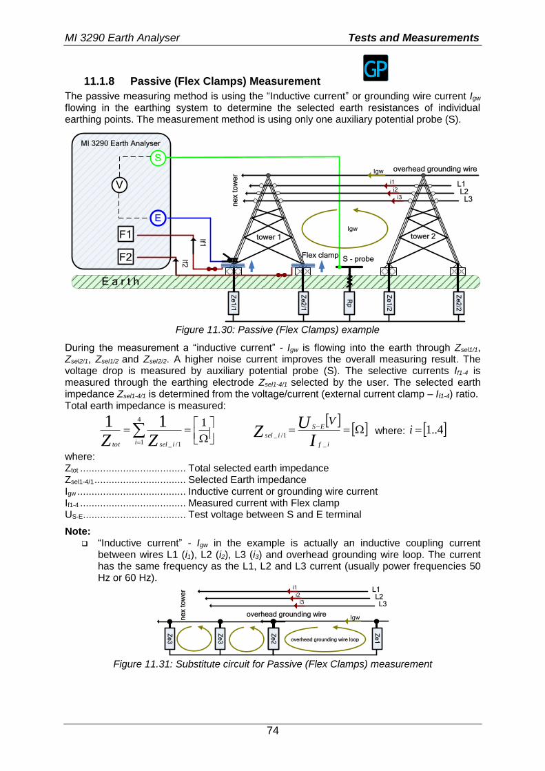
MI 3290 Earth Analyser Tests and Measurements
74
11.1.8 Passive (Flex Clamps) Measurement
The passive measuring method is using the “Inductive current” or grounding wire current Igw flowing in the earthing system to determine the selected earth resistances of individual earthing points. The measurement method is using only one auxiliary potential probe (S).
E a r t h
S
E
MI 3290 Earth Analyser
Ze
1/1
Rp
V
S - probe
tower 1 Z
e2
/1
F2
F1
Flex clamp
If1
If2
tower 2
Ze
2/2
Ze
1/2
L1L2
L3
i1
i2
i3
ne
x t
ow
er
overhead grounding wire
Igw
Igw
Figure 11.30: Passive (Flex Clamps) example
During the measurement a “inductive current” - Igw is flowing into the earth through Zsel1/1, Zsel2/1, Zsel1/2 and Zsel2/2. A higher noise current improves the overall measuring result. The voltage drop is measured by auxiliary potential probe (S). The selective currents If1-4 is measured through the earthing electrode Zsel1-4/1 selected by the user. The selected earth impedance Zsel1-4/1 is determined from the voltage/current (external current clamp – If1-4) ratio. Total earth impedance is measured:
14
1 1/_
11i iseltot ZZ
IU
Zif
ES
isel
V
_
1/_ where: 4..1i
where: Ztot ..................................... Total selected earth impedance Zsel1-4/1 ................................ Selected Earth impedance Igw ...................................... Inductive current or grounding wire current If1-4 ..................................... Measured current with Flex clamp US-E .................................... Test voltage between S and E terminal
Note: “Inductive current” - Igw in the example is actually an inductive coupling current
between wires L1 (i1), L2 (i2), L3 (i3) and overhead grounding wire loop. The current has the same frequency as the L1, L2 and L3 current (usually power frequencies 50 Hz or 60 Hz).
Ze
1
L1L2L3
i1
i2
i3
overhead grounding wireIgw
overhead grounding wire loop
Re
1
ne
x t
ow
er
Ze
2
Ze
3
Ze
3
Figure 11.31: Substitute circuit for Passive (Flex Clamps) measurement
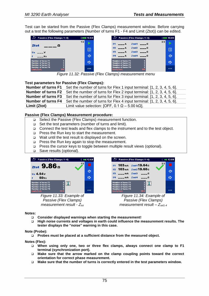
MI 3290 Earth Analyser Tests and Measurements
75
Test can be started from the Passive (Flex Clamps) measurement window. Before carrying out a test the following parameters (Number of turns F1 - F4 and Limit (Ztot)) can be edited.
Figure 11.32: Passive (Flex Clamps) measurement menu
Test parameters for Passive (Flex Clamps): Number of turns F1 Set the number of turns for Flex 1 input terminal: [1, 2, 3, 4, 5, 6].
Number of turns F2 Set the number of turns for Flex 2 input terminal: [1, 2, 3, 4, 5, 6].
Number of turns F3 Set the number of turns for Flex 3 input terminal: [1, 2, 3, 4, 5, 6].
Number of turns F4 Set the number of turns for Flex 4 input terminal: [1, 2, 3, 4, 5, 6].
Limit (Ztot) Limit value selection: [OFF, 0.1 Ω – 5.00 kΩ].
Passive (Flex Clamps) Measurement procedure:
Select the Passive (Flex Clamps) measurement function. Set the test parameters (number of turns and limit). Connect the test leads and flex clamps to the instrument and to the test object. Press the Run key to start the measurement. Wait until the test result is displayed on the screen. Press the Run key again to stop the measurement. Press the cursor keys to toggle between multiple result views (optional). Save results (optional).
Figure 11.33: Example of
Passive (Flex Clamps) measurement result - Ztot
Figure 11.34: Example of Passive (Flex Clamps)
measurement result – Zsel1-4 Notes:
Consider displayed warnings when starting the measurement! High noise currents and voltages in earth could influence the measurement results. The
tester displays the “noise” warning in this case.
Note (Probe): Probes must be placed at a sufficient distance from the measured object.
Notes (Flex): When using only one, two or three flex clamps, always connect one clamp to F1
terminal (synchronization port). Make sure that the arrow marked on the clamp coupling points toward the correct
orientation for correct phase measurement. Make sure that the number of turns is correctly entered in the test parameters window.
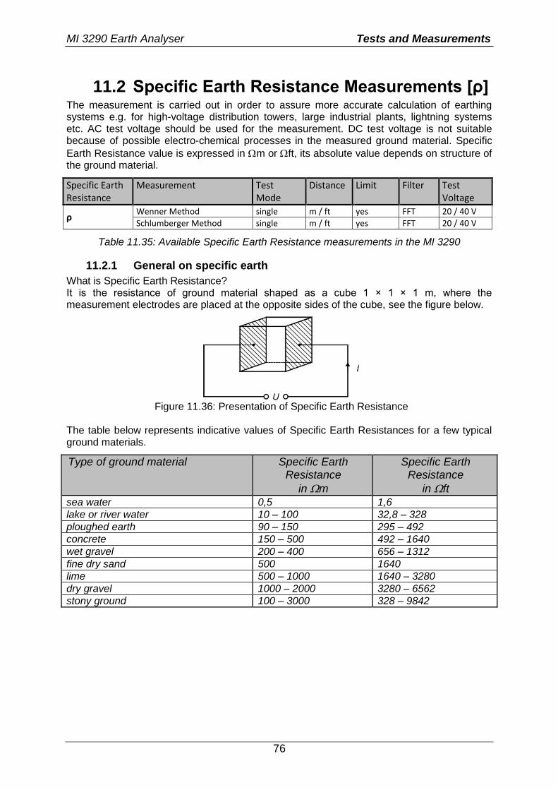
MI 3290 Earth Analyser Tests and Measurements
76
11.2 Specific Earth Resistance Measurements [ρ] The measurement is carried out in order to assure more accurate calculation of earthing systems e.g. for high-voltage distribution towers, large industrial plants, lightning systems etc. AC test voltage should be used for the measurement. DC test voltage is not suitable because of possible electro-chemical processes in the measured ground material. Specific
Earth Resistance value is expressed in m or ft, its absolute value depends on structure of the ground material.
Specific Earth Resistance
Measurement Test Mode
Distance Limit Filter Test Voltage
ρ Wenner Method single m / ft yes FFT 20 / 40 V
Schlumberger Method single m / ft yes FFT 20 / 40 V
Table 11.35: Available Specific Earth Resistance measurements in the MI 3290
11.2.1 General on specific earth
What is Specific Earth Resistance? It is the resistance of ground material shaped as a cube 1 × 1 × 1 m, where the measurement electrodes are placed at the opposite sides of the cube, see the figure below.
Figure 11.36: Presentation of Specific Earth Resistance
The table below represents indicative values of Specific Earth Resistances for a few typical ground materials.
Type of ground material Specific Earth Resistance
in m
Specific Earth Resistance
in ft
sea water 0,5 1,6
lake or river water 10 – 100 32,8 – 328
ploughed earth 90 – 150 295 – 492
concrete 150 – 500 492 – 1640
wet gravel 200 – 400 656 – 1312
fine dry sand 500 1640
lime 500 – 1000 1640 – 3280
dry gravel 1000 – 2000 3280 – 6562
stony ground 100 – 3000 328 – 9842

MI 3290 Earth Analyser Tests and Measurements
77
11.2.2 Wenner method Measurement
Place the four earth probes on a straight line, at a distance a from one another and at a depth b < a/20. Distance a must be between 0,1 m and 29,9 m. Connect the cables to the probes, then to terminals H, S, ES, and E.
E a r t h
H
S
ES
E
MI 3290 Earth Analyser
a
G
V
A
S - probeES - probeE - probe H - probe
a a
b
Figure 11.37: Wenner method example
Wenner method with equal distances between test probes:
20
ab
mRa ewenner
2
where: Re ..................................... Measured earth resistance in 4-pole method a ....................................... Distance between earth probes b ....................................... Depth of earth probes π ....................................... Number π is a mathematical constant (3.14159)
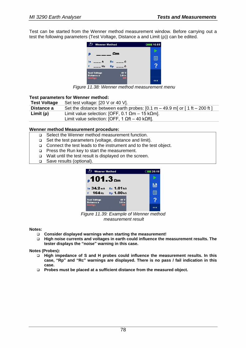
MI 3290 Earth Analyser Tests and Measurements
78
Test can be started from the Wenner method measurement window. Before carrying out a test the following parameters (Test Voltage, Distance a and Limit (ρ)) can be edited.
Figure 11.38: Wenner method measurement menu
Test parameters for Wenner method: Test Voltage Set test voltage: [20 V or 40 V].
Distance a Set the distance between earth probes: [0.1 m – 49.9 m] or [ 1 ft – 200 ft ]
Limit (ρ) Limit value selection: [OFF, 0.1 Ωm – 15 kΩm]. Limit value selection: [OFF, 1 Ωft – 40 kΩft].
Wenner method Measurement procedure:
Select the Wenner method measurement function. Set the test parameters (voltage, distance and limit). Connect the test leads to the instrument and to the test object. Press the Run key to start the measurement. Wait until the test result is displayed on the screen. Save results (optional).
Figure 11.39: Example of Wenner method
measurement result Notes:
Consider displayed warnings when starting the measurement! High noise currents and voltages in earth could influence the measurement results. The
tester displays the “noise” warning in this case.
Notes (Probes): High impedance of S and H probes could influence the measurement results. In this
case, “Rp” and “Rc” warnings are displayed. There is no pass / fail indication in this case.
Probes must be placed at a sufficient distance from the measured object.
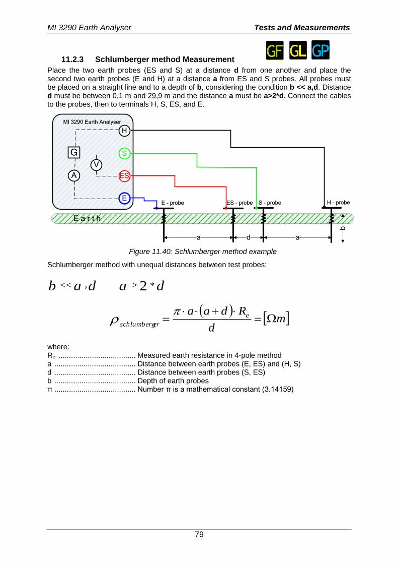
MI 3290 Earth Analyser Tests and Measurements
79
11.2.3 Schlumberger method Measurement
Place the two earth probes (ES and S) at a distance d from one another and place the second two earth probes (E and H) at a distance a from ES and S probes. All probes must be placed on a straight line and to a depth of b, considering the condition b << a,d. Distance d must be between 0,1 m and 29,9 m and the distance a must be a>2*d. Connect the cables to the probes, then to terminals H, S, ES, and E.
E a r t h
H
S
ES
E
MI 3290 Earth Analyser
a
G
V
A
S - probeES - probeE - probe H - probe
d a
b
Figure 11.40: Schlumberger method example
Schlumberger method with unequal distances between test probes:
dab , da 2
m
d
Rdaa e
erschlumberg
where: Re ..................................... Measured earth resistance in 4-pole method a ....................................... Distance between earth probes (E, ES) and (H, S) d ....................................... Distance between earth probes (S, ES) b ....................................... Depth of earth probes π ....................................... Number π is a mathematical constant (3.14159)
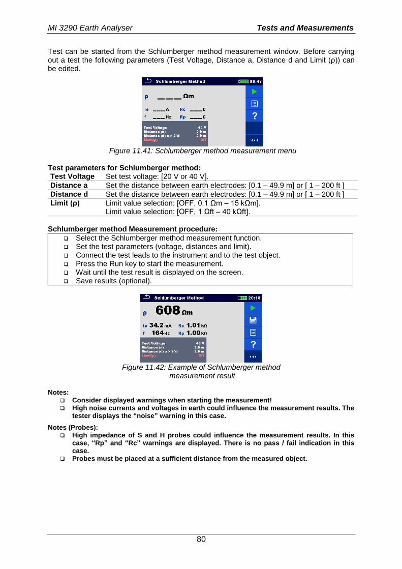
MI 3290 Earth Analyser Tests and Measurements
80
Test can be started from the Schlumberger method measurement window. Before carrying out a test the following parameters (Test Voltage, Distance a, Distance d and Limit (ρ)) can be edited.
Figure 11.41: Schlumberger method measurement menu
Test parameters for Schlumberger method: Test Voltage Set test voltage: [20 V or 40 V].
Distance a Set the distance between earth electrodes: [0.1 – 49.9 m] or [ 1 – 200 ft ]
Distance d Set the distance between earth electrodes: [0.1 – 49.9 m] or [ 1 – 200 ft ]
Limit (ρ) Limit value selection: [OFF, 0.1 Ωm – 15 kΩm]. Limit value selection: [OFF, 1 Ωft – 40 kΩft].
Schlumberger method Measurement procedure:
Select the Schlumberger method measurement function. Set the test parameters (voltage, distances and limit). Connect the test leads to the instrument and to the test object. Press the Run key to start the measurement. Wait until the test result is displayed on the screen. Save results (optional).
Figure 11.42: Example of Schlumberger method
measurement result Notes:
Consider displayed warnings when starting the measurement! High noise currents and voltages in earth could influence the measurement results. The
tester displays the “noise” warning in this case.
Notes (Probes): High impedance of S and H probes could influence the measurement results. In this
case, “Rp” and “Rc” warnings are displayed. There is no pass / fail indication in this case.
Probes must be placed at a sufficient distance from the measured object.
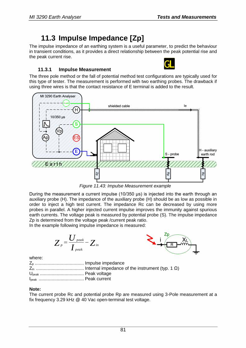
MI 3290 Earth Analyser Tests and Measurements
81
11.3 Impulse Impedance [Zp] The impulse impedance of an earthing system is a useful parameter, to predict the behaviour in transient conditions, as it provides a direct relationship between the peak potential rise and the peak current rise.
11.3.1 Impulse Measurement
The three pole method or the fall of potential method test configurations are typically used for this type of tester. The measurement is performed with two earthing probes. The drawback if using three wires is that the contact resistance of E terminal is added to the result.
E a r t h
H
S
ES
E
MI 3290 Earth Analyser
Zp
Guard
Rp
Vp
Ap
S - probeH - auxiliary
earth rod
Rc
Ie
10/350 µs
shielded cable
Figure 11.43: Impulse Measurement example
During the measurement a current impulse (10/350 µs) is injected into the earth through an auxiliary probe (H). The impedance of the auxiliary probe (H) should be as low as possible in order to inject a high test current. The impedance Rc can be decreased by using more probes in parallel. A higher injected current impulse improves the immunity against spurious earth currents. The voltage peak is measured by potential probe (S). The impulse impedance Zp is determined from the voltage peak /current peak ratio. In the example following impulse impedance is measured:
ZIU
Z in
peak
peak
p R
XLiZp
where: Zp ...................................... Impulse impedance Zin ..................................... Internal impedance of the instrument (typ. 1 Ω) Upeak .................................. Peak voltage Ipeak ................................... Peak current Note: The current probe Rc and potential probe Rp are measured using 3-Pole measurement at a fix frequency 3.29 kHz @ 40 Vac open-terminal test voltage.
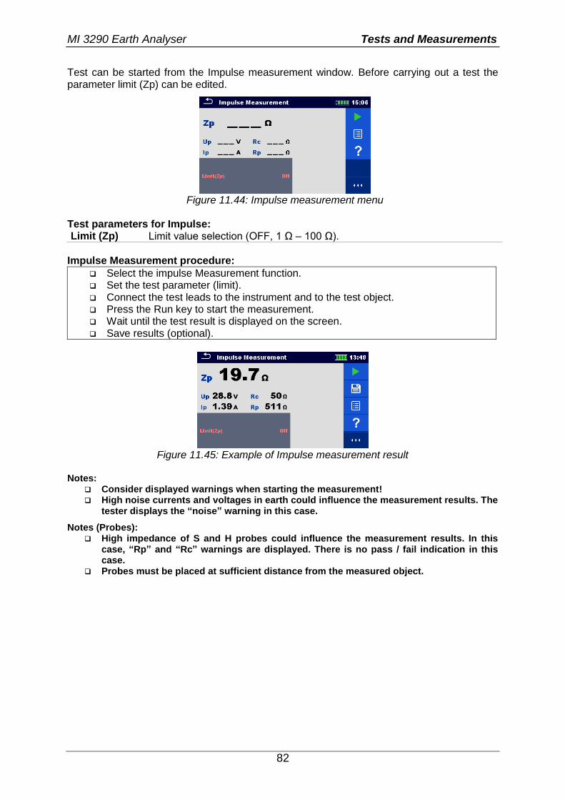
MI 3290 Earth Analyser Tests and Measurements
82
Test can be started from the Impulse measurement window. Before carrying out a test the parameter limit (Zp) can be edited.
Figure 11.44: Impulse measurement menu
Test parameters for Impulse: Limit (Zp) Limit value selection (OFF, 1 Ω – 100 Ω).
Impulse Measurement procedure:
Select the impulse Measurement function. Set the test parameter (limit). Connect the test leads to the instrument and to the test object. Press the Run key to start the measurement. Wait until the test result is displayed on the screen. Save results (optional).
Figure 11.45: Example of Impulse measurement result
Notes:
Consider displayed warnings when starting the measurement! High noise currents and voltages in earth could influence the measurement results. The
tester displays the “noise” warning in this case.
Notes (Probes): High impedance of S and H probes could influence the measurement results. In this
case, “Rp” and “Rc” warnings are displayed. There is no pass / fail indication in this case.
Probes must be placed at sufficient distance from the measured object.
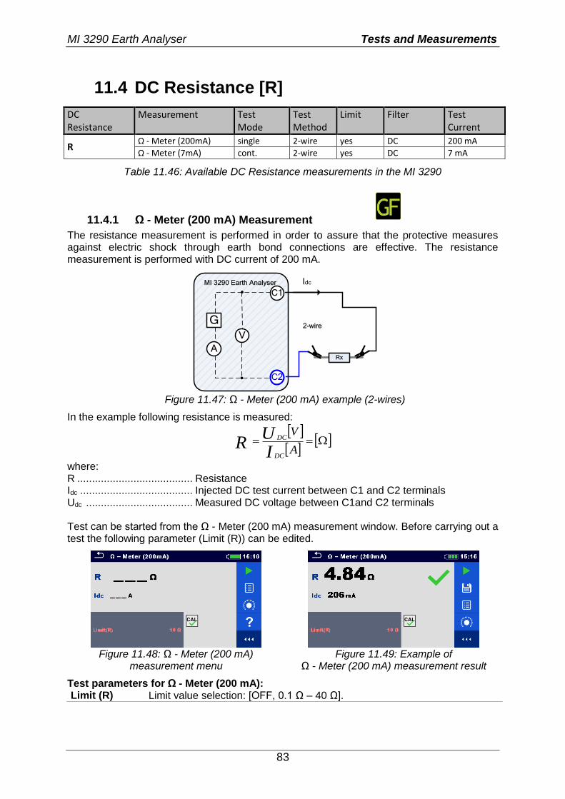
MI 3290 Earth Analyser Tests and Measurements
83
11.4 DC Resistance [R]
DC Resistance
Measurement Test Mode
Test Method
Limit Filter Test Current
R Ω - Meter (200mA) single 2-wire yes DC 200 mA
Ω - Meter (7mA) cont. 2-wire yes DC 7 mA
Table 11.46: Available DC Resistance measurements in the MI 3290
11.4.1 Ω - Meter (200 mA) Measurement
The resistance measurement is performed in order to assure that the protective measures against electric shock through earth bond connections are effective. The resistance measurement is performed with DC current of 200 mA.
Idc
C1
C2
MI 3290 Earth Analyser
G
V
ARx
2-wire
Figure 11.47: Ω - Meter (200 mA) example (2-wires)
In the example following resistance is measured:
A
V
IU
RDC
DC
where: R ....................................... Resistance Idc ...................................... Injected DC test current between C1 and C2 terminals Udc .................................... Measured DC voltage between C1and C2 terminals Test can be started from the Ω - Meter (200 mA) measurement window. Before carrying out a test the following parameter (Limit (R)) can be edited.
Figure 11.48: Ω - Meter (200 mA)
measurement menu Figure 11.49: Example of
Ω - Meter (200 mA) measurement result
Test parameters for Ω - Meter (200 mA): Limit (R) Limit value selection: [OFF, 0.1 Ω – 40 Ω].
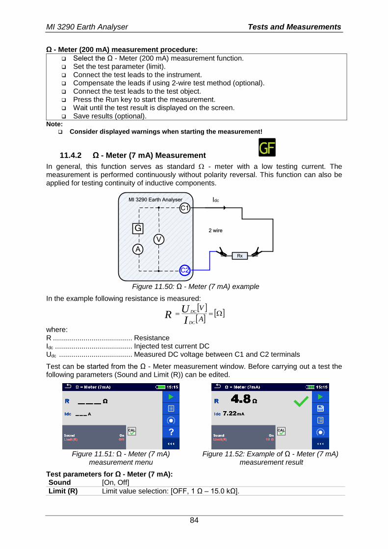
MI 3290 Earth Analyser Tests and Measurements
84
Ω - Meter (200 mA) measurement procedure:
Select the Ω - Meter (200 mA) measurement function. Set the test parameter (limit). Connect the test leads to the instrument. Compensate the leads if using 2-wire test method (optional). Connect the test leads to the test object. Press the Run key to start the measurement. Wait until the test result is displayed on the screen. Save results (optional).
Note: Consider displayed warnings when starting the measurement!
11.4.2 Ω - Meter (7 mA) Measurement
In general, this function serves as standard - meter with a low testing current. The measurement is performed continuously without polarity reversal. This function can also be applied for testing continuity of inductive components.
Idc
C1
C2
MI 3290 Earth Analyser
G
V
ARx
2 wire
Figure 11.50: Ω - Meter (7 mA) example
In the example following resistance is measured:
A
V
IU
RDC
DC
where: R ....................................... Resistance Idc ...................................... Injected test current DC Udc .................................... Measured DC voltage between C1 and C2 terminals
Test can be started from the Ω - Meter measurement window. Before carrying out a test the following parameters (Sound and Limit (R)) can be edited.
Figure 11.51: Ω - Meter (7 mA)
measurement menu Figure 11.52: Example of Ω - Meter (7 mA)
measurement result
Test parameters for Ω - Meter (7 mA): Sound [On, Off]
Limit (R) Limit value selection: [OFF, 1 Ω – 15.0 kΩ].
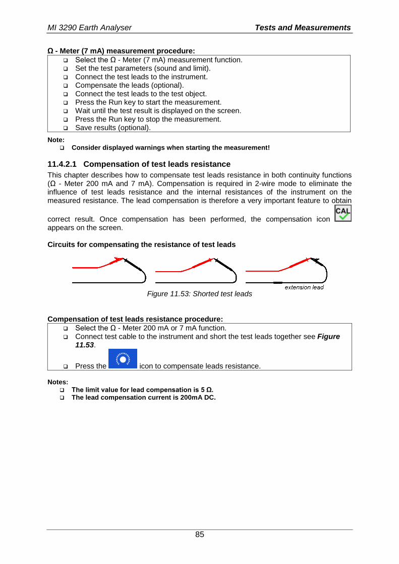
MI 3290 Earth Analyser Tests and Measurements
85
Ω - Meter (7 mA) measurement procedure:
Select the Ω - Meter (7 mA) measurement function. Set the test parameters (sound and limit). Connect the test leads to the instrument. Compensate the leads (optional). Connect the test leads to the test object. Press the Run key to start the measurement. Wait until the test result is displayed on the screen. Press the Run key to stop the measurement. Save results (optional).
Note: Consider displayed warnings when starting the measurement!
11.4.2.1 Compensation of test leads resistance
This chapter describes how to compensate test leads resistance in both continuity functions (Ω - Meter 200 mA and 7 mA). Compensation is required in 2-wire mode to eliminate the influence of test leads resistance and the internal resistances of the instrument on the measured resistance. The lead compensation is therefore a very important feature to obtain
correct result. Once compensation has been performed, the compensation icon appears on the screen. Circuits for compensating the resistance of test leads
Figure 11.53: Shorted test leads
Compensation of test leads resistance procedure:
Select the Ω - Meter 200 mA or 7 mA function. Connect test cable to the instrument and short the test leads together see Figure
11.53.
Press the icon to compensate leads resistance. Notes:
The limit value for lead compensation is 5 Ω. The lead compensation current is 200mA DC.
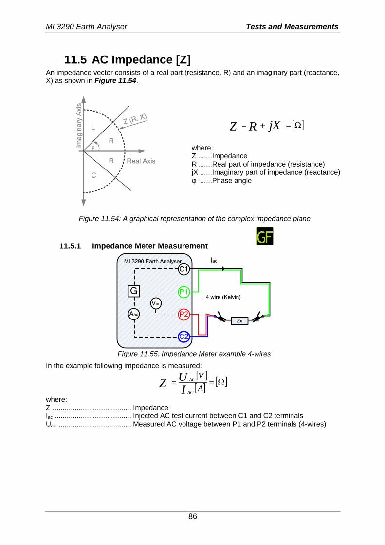
MI 3290 Earth Analyser Tests and Measurements
86
11.5 AC Impedance [Z] An impedance vector consists of a real part (resistance, R) and an imaginary part (reactance, X) as shown in Figure 11.54.
Ima
gin
ary
Axis
R
Real Axis
L
C
R
φ
Z (R, X)
jXRZ
where: Z .......Impedance R .......Real part of impedance (resistance) jX ......Imaginary part of impedance (reactance) φ ......Phase angle
Figure 11.54: A graphical representation of the complex impedance plane
11.5.1 Impedance Meter Measurement
C1
P1
P2
C2
MI 3290 Earth Analyser
G
Vac
Aac
Zx
4 wire (Kelvin)
Iac
Figure 11.55: Impedance Meter example 4-wires
In the example following impedance is measured:
A
V
IU
ZAC
AC
where: Z ....................................... Impedance Iac ...................................... Injected AC test current between C1 and C2 terminals Uac .................................... Measured AC voltage between P1 and P2 terminals (4-wires)
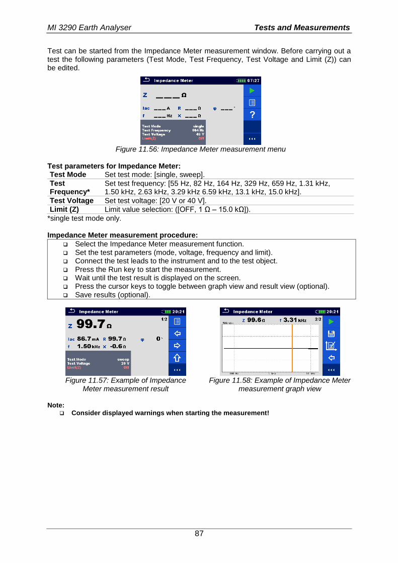
MI 3290 Earth Analyser Tests and Measurements
87
Test can be started from the Impedance Meter measurement window. Before carrying out a test the following parameters (Test Mode, Test Frequency, Test Voltage and Limit (Z)) can be edited.
Figure 11.56: Impedance Meter measurement menu
Test parameters for Impedance Meter: Test Mode Set test mode: [single, sweep].
Test Frequency*
Set test frequency: [55 Hz, 82 Hz, 164 Hz, 329 Hz, 659 Hz, 1.31 kHz, 1.50 kHz, 2.63 kHz, 3.29 kHz 6.59 kHz, 13.1 kHz, 15.0 kHz].
Test Voltage Set test voltage: [20 V or 40 V].
Limit (Z) Limit value selection: ([OFF, 1 Ω – 15.0 kΩ]).
*single test mode only. Impedance Meter measurement procedure:
Select the Impedance Meter measurement function. Set the test parameters (mode, voltage, frequency and limit). Connect the test leads to the instrument and to the test object. Press the Run key to start the measurement. Wait until the test result is displayed on the screen. Press the cursor keys to toggle between graph view and result view (optional). Save results (optional).
Figure 11.57: Example of Impedance
Meter measurement result Figure 11.58: Example of Impedance Meter
measurement graph view Note:
Consider displayed warnings when starting the measurement!
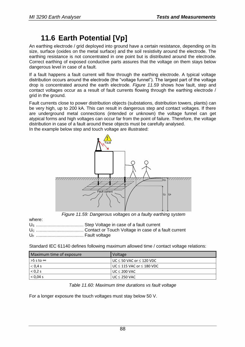
MI 3290 Earth Analyser Tests and Measurements
88
11.6 Earth Potential [Vp] An earthing electrode / grid deployed into ground have a certain resistance, depending on its size, surface (oxides on the metal surface) and the soil resistivity around the electrode. The earthing resistance is not concentrated in one point but is distributed around the electrode. Correct earthing of exposed conductive parts assures that the voltage on them stays below dangerous level in case of a fault.
If a fault happens a fault current will flow through the earthing electrode. A typical voltage distribution occurs around the electrode (the “voltage funnel”). The largest part of the voltage drop is concentrated around the earth electrode. Figure 11.59 shows how fault, step and contact voltages occur as a result of fault currents flowing through the earthing electrode / grid in the ground.
Fault currents close to power distribution objects (substations, distribution towers, plants) can be very high, up to 200 kA. This can result in dangerous step and contact voltages. If there are underground metal connections (intended or unknown) the voltage funnel can get atypical forms and high voltages can occur far from the point of failure. Therefore, the voltage distribution in case of a fault around these objects must be carefully analysed. In the example below step and touch voltage are illustrated:
Figure 11.59: Dangerous voltages on a faulty earthing system
where: US ..................................... Step Voltage in case of a fault current UC ..................................... Contact or Touch Voltage in case of a fault current UF ..................................... Fault voltage
Standard IEC 61140 defines following maximum allowed time / contact voltage relations:
Maximum time of exposure Voltage
>5 s to ∞ UC 50 VAC or 120 VDC
0,4 s UC 115 VAC or 180 VDC
< 0,2 s UC 200 VAC
< 0,04 s UC 250 VAC
Table 11.60: Maximum time durations vs fault voltage
For a longer exposure the touch voltages must stay below 50 V.
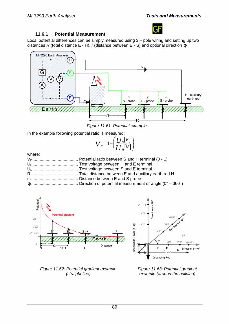
MI 3290 Earth Analyser Tests and Measurements
89
11.6.1 Potential Measurement
Local potential differences can be simply measured using 3 – pole wiring and setting up two distances R (total distance E - H), r (distance between E - S) and optional direction ϕ.
E a r t h
Ie
H
S
E
MI 3290 Earth Analyser
G
V
A
1
S - probe
H - auxiliary
earth rod
R
r1
2
S - probe
...
S - probe
V
Figure 11.61: Potential example
In the example following potential ratio is measured:
V
V
UU
VH
S
P1
where: VP ..................................... Potential ratio between S and H terminal (0 - 1) UH ..................................... Test voltage between H and E terminal US ..................................... Test voltage between S and E terminal R ....................................... Total distance between E and auxiliary earth rod H r ........................................ Distance between E and S probe ϕ ....................................... Direction of potential measurement or angle (0° – 360°)
E a r t h
H
r1r2
r n+1Distance
Po
ten
tia
l
Potential gradient
E
S 1 S 2 S n+1
Vp1
Vp2
Vp n+1
Tra
nsm
issio
n T
ow
er
(4 le
g)
r1r2
r n+1
Grounding Rod
Vp1 Vp2 Vp n+1
Direction ϕ = 0°
Vp1
Vp2
Direct
ion ϕ
= 4
5°Dir
ectio
n ϕ
= 9
0°
Vp1
Vp2
Vp n+1
Vp n+1
ϕ
ϕ3
Figure 11.62: Potential gradient example
(straight line) Figure 11.63: Potential gradient example (around the building)
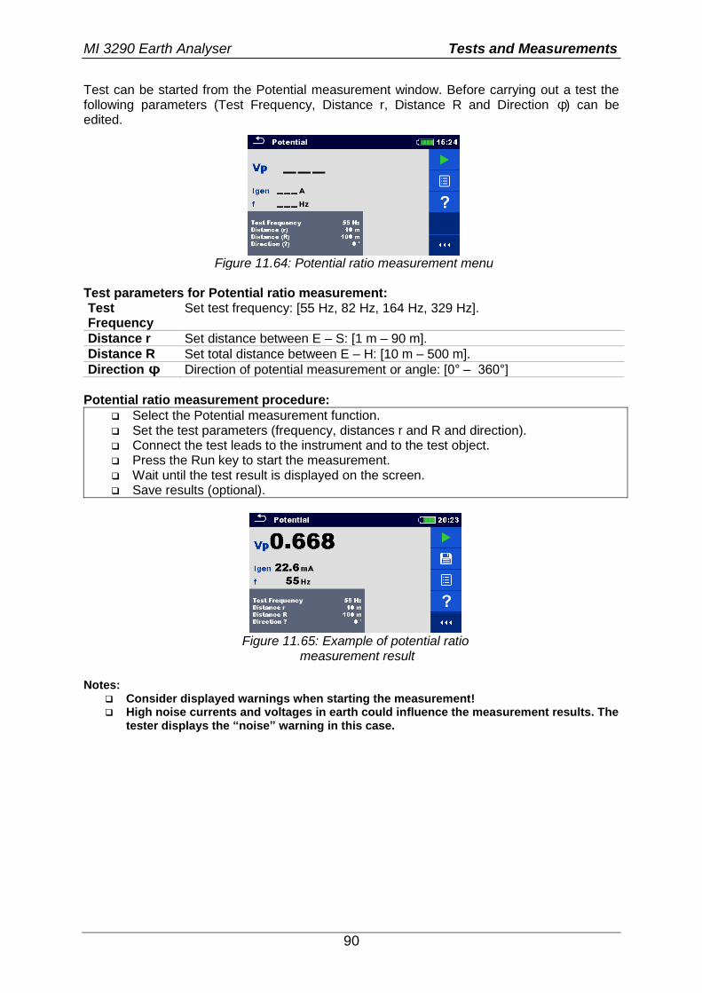
MI 3290 Earth Analyser Tests and Measurements
90
Test can be started from the Potential measurement window. Before carrying out a test the following parameters (Test Frequency, Distance r, Distance R and Direction ϕ) can be edited.
Figure 11.64: Potential ratio measurement menu
Test parameters for Potential ratio measurement: Test Frequency
Set test frequency: [55 Hz, 82 Hz, 164 Hz, 329 Hz].
Distance r Set distance between E – S: [1 m – 90 m].
Distance R Set total distance between E – H: [10 m – 500 m].
Direction ϕ Direction of potential measurement or angle: [0° – 360°]
Potential ratio measurement procedure:
Select the Potential measurement function. Set the test parameters (frequency, distances r and R and direction). Connect the test leads to the instrument and to the test object. Press the Run key to start the measurement. Wait until the test result is displayed on the screen. Save results (optional).
Figure 11.65: Example of potential ratio
measurement result Notes:
Consider displayed warnings when starting the measurement! High noise currents and voltages in earth could influence the measurement results. The
tester displays the “noise” warning in this case.
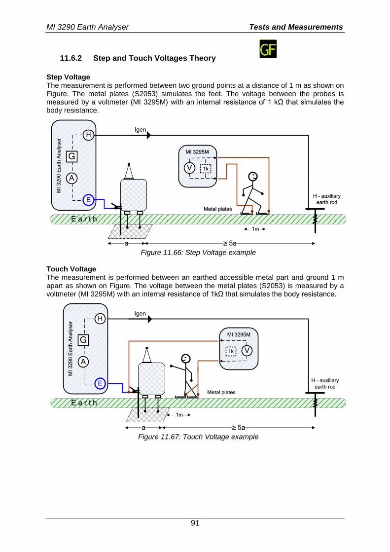
MI 3290 Earth Analyser Tests and Measurements
91
11.6.2 Step and Touch Voltages Theory
Step Voltage The measurement is performed between two ground points at a distance of 1 m as shown on Figure. The metal plates (S2053) simulates the feet. The voltage between the probes is measured by a voltmeter (MI 3295M) with an internal resistance of 1 kΩ that simulates the body resistance.
E a r t h
Igen H
E
MI
32
90
Ea
rth
An
aly
se
r
G
V
A
H - auxiliary
earth rod
≥ 5aa
1m
1k
Metal plates
MI 3295M
Figure 11.66: Step Voltage example
Touch Voltage The measurement is performed between an earthed accessible metal part and ground 1 m apart as shown on Figure. The voltage between the metal plates (S2053) is measured by a voltmeter (MI 3295M) with an internal resistance of 1kΩ that simulates the body resistance.
E a r t h
Igen
H - auxiliary
earth rod
≥ 5aa
1m
Metal plates
V1k
MI 3295M
H
E
MI
32
90
Ea
rth
An
aly
se
r
G
A
Figure 11.67: Touch Voltage example
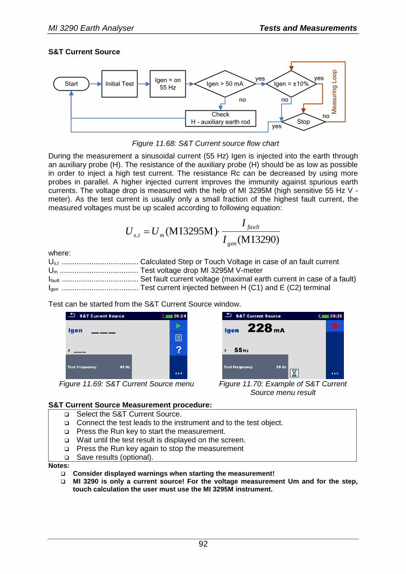
MI 3290 Earth Analyser Tests and Measurements
92
S&T Current Source
Start Initial TestIgen = on
55 HzIgen > 50 mA
Check
H - auxiliary earth rod Stop
yes
no
yes
yes
no
Igen = ±10%
no
Me
asu
rin
g L
oo
p
Figure 11.68: S&T Current source flow chart
During the measurement a sinusoidal current (55 Hz) Igen is injected into the earth through an auxiliary probe (H). The resistance of the auxiliary probe (H) should be as low as possible in order to inject a high test current. The resistance Rc can be decreased by using more probes in parallel. A higher injected current improves the immunity against spurious earth currents. The voltage drop is measured with the help of MI 3295M (high sensitive 55 Hz V - meter). As the test current is usually only a small fraction of the highest fault current, the measured voltages must be up scaled according to following equation:
3290) (MI3295M) (MI,
gen
fault
mtsI
IUU
where: Us,t .................................... Calculated Step or Touch Voltage in case of an fault current Um ..................................... Test voltage drop MI 3295M V-meter Ifault .................................... Set fault current voltage (maximal earth current in case of a fault) Igen .................................... Test current injected between H (C1) and E (C2) terminal
Test can be started from the S&T Current Source window.
Figure 11.69: S&T Current Source menu Figure 11.70: Example of S&T Current
Source menu result
S&T Current Source Measurement procedure:
Select the S&T Current Source. Connect the test leads to the instrument and to the test object. Press the Run key to start the measurement. Wait until the test result is displayed on the screen. Press the Run key again to stop the measurement Save results (optional).
Notes: Consider displayed warnings when starting the measurement! MI 3290 is only a current source! For the voltage measurement Um and for the step,
touch calculation the user must use the MI 3295M instrument.
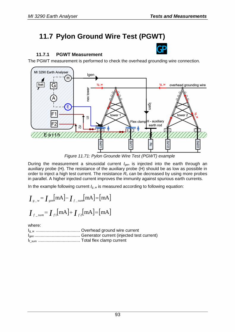
MI 3290 Earth Analyser Tests and Measurements
93
11.7 Pylon Ground Wire Test (PGWT)
11.7.1 PGWT Measurement
The PGWT measurement is performed to check the overhead grounding wire connection.
E a r t hZ
e2
/1
Rc
tower 1
Ze
1/1
F2
F1
Flex clamp
If1
If2
tower 2
Ze
2/2
Ze
1/2
ne
x t
ow
er
overhead grounding wireIg_w
H
E
MI 3290 Earth Analyser
G
A
H - auxiliary
earth rod
Igen
Ig_w
Ig_w
Ige
n
fset
Figure 11.71: Pylon Grounde Wire Test (PGWT) example
During the measurement a sinusoidal current Igen is injected into the earth through an auxiliary probe (H). The resistance of the auxiliary probe (H) should be as low as possible in order to inject a high test current. The resistance Rc can be decreased by using more probes in parallel. A higher injected current improves the immunity against spurious earth currents.
In the example following current Ig_w is measured according to following equation:
mAmAmA__
III sumfgenwg
mAmAmA21_
III ffsumf
where: Ig_w .................................... Overhead ground wire current Igen ..................................... Generator current (injected test current) If_sum .................................. Total flex clamp current
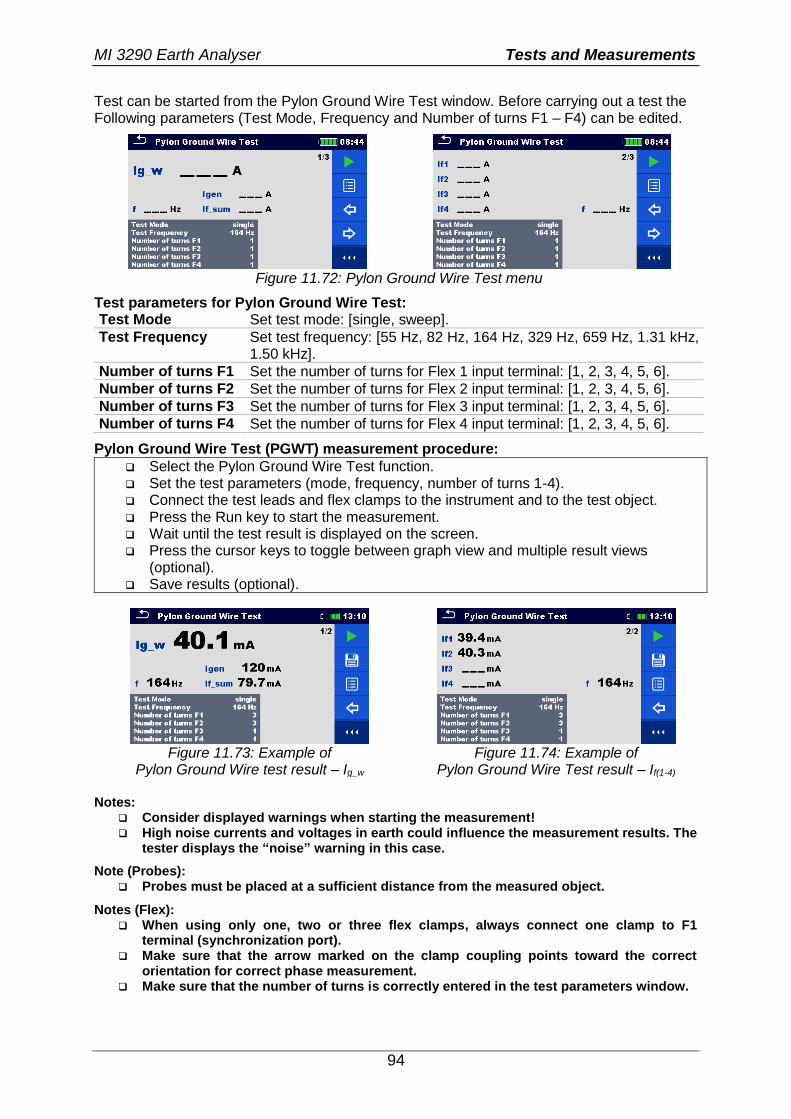
MI 3290 Earth Analyser Tests and Measurements
94
Test can be started from the Pylon Ground Wire Test window. Before carrying out a test the Following parameters (Test Mode, Frequency and Number of turns F1 – F4) can be edited.
Figure 11.72: Pylon Ground Wire Test menu
Test parameters for Pylon Ground Wire Test: Test Mode Set test mode: [single, sweep].
Test Frequency Set test frequency: [55 Hz, 82 Hz, 164 Hz, 329 Hz, 659 Hz, 1.31 kHz, 1.50 kHz].
Number of turns F1 Set the number of turns for Flex 1 input terminal: [1, 2, 3, 4, 5, 6].
Number of turns F2 Set the number of turns for Flex 2 input terminal: [1, 2, 3, 4, 5, 6].
Number of turns F3 Set the number of turns for Flex 3 input terminal: [1, 2, 3, 4, 5, 6].
Number of turns F4 Set the number of turns for Flex 4 input terminal: [1, 2, 3, 4, 5, 6].
Pylon Ground Wire Test (PGWT) measurement procedure:
Select the Pylon Ground Wire Test function. Set the test parameters (mode, frequency, number of turns 1-4). Connect the test leads and flex clamps to the instrument and to the test object. Press the Run key to start the measurement. Wait until the test result is displayed on the screen. Press the cursor keys to toggle between graph view and multiple result views
(optional). Save results (optional).
Figure 11.73: Example of
Pylon Ground Wire test result – Ig_w Figure 11.74: Example of
Pylon Ground Wire Test result – If(1-4) Notes:
Consider displayed warnings when starting the measurement! High noise currents and voltages in earth could influence the measurement results. The
tester displays the “noise” warning in this case.
Note (Probes): Probes must be placed at a sufficient distance from the measured object.
Notes (Flex): When using only one, two or three flex clamps, always connect one clamp to F1
terminal (synchronization port). Make sure that the arrow marked on the clamp coupling points toward the correct
orientation for correct phase measurement. Make sure that the number of turns is correctly entered in the test parameters window.
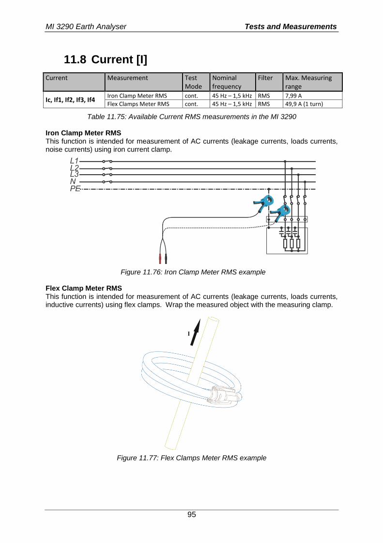
MI 3290 Earth Analyser Tests and Measurements
95
11.8 Current [I]
Current Measurement Test Mode
Nominal frequency
Filter Max. Measuring range
Ic, If1, If2, If3, If4 Iron Clamp Meter RMS cont. 45 Hz – 1,5 kHz RMS 7,99 A
Flex Clamps Meter RMS cont. 45 Hz – 1,5 kHz RMS 49,9 A (1 turn)
Table 11.75: Available Current RMS measurements in the MI 3290 Iron Clamp Meter RMS This function is intended for measurement of AC currents (leakage currents, loads currents, noise currents) using iron current clamp.
Figure 11.76: Iron Clamp Meter RMS example Flex Clamp Meter RMS This function is intended for measurement of AC currents (leakage currents, loads currents, inductive currents) using flex clamps. Wrap the measured object with the measuring clamp.
Figure 11.77: Flex Clamps Meter RMS example
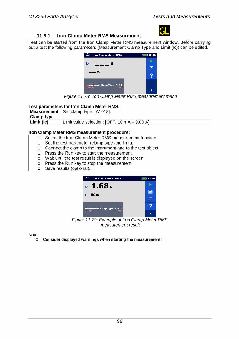
MI 3290 Earth Analyser Tests and Measurements
96
11.8.1 Iron Clamp Meter RMS Measurement
Test can be started from the Iron Clamp Meter RMS measurement window. Before carrying out a test the following parameters (Measurement Clamp Type and Limit (Ic)) can be edited.
Figure 11.78: Iron Clamp Meter RMS measurement menu
Test parameters for Iron Clamp Meter RMS: Measurement Clamp type
Set clamp type: [A1018].
Limit (Ic) Limit value selection: [OFF, 10 mA – 9.00 A].
Iron Clamp Meter RMS measurement procedure:
Select the Iron Clamp Meter RMS measurement function. Set the test parameter (clamp type and limit). Connect the clamp to the instrument and to the test object. Press the Run key to start the measurement. Wait until the test result is displayed on the screen. Press the Run key to stop the measurement. Save results (optional).
Figure 11.79: Example of Iron Clamp Meter RMS
measurement result Note:
Consider displayed warnings when starting the measurement!
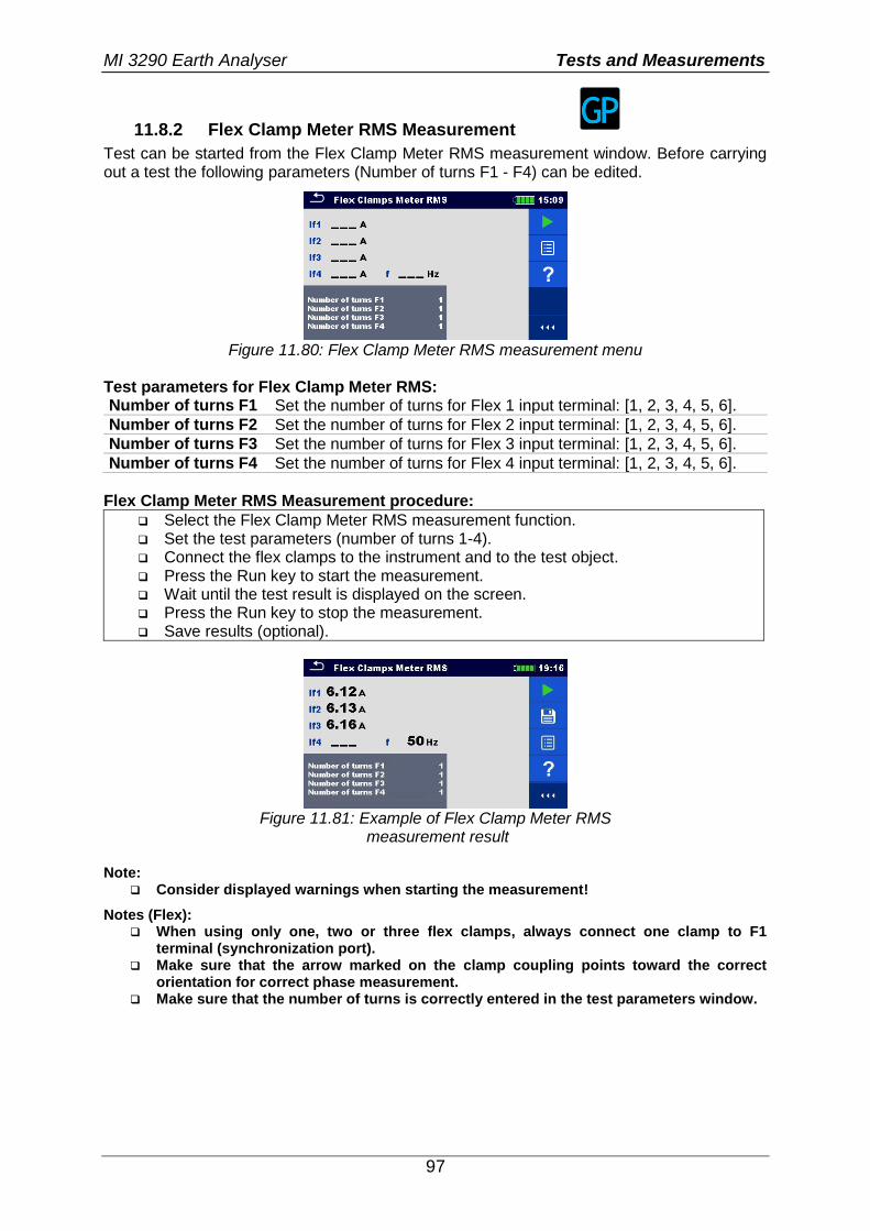
MI 3290 Earth Analyser Tests and Measurements
97
11.8.2 Flex Clamp Meter RMS Measurement
Test can be started from the Flex Clamp Meter RMS measurement window. Before carrying out a test the following parameters (Number of turns F1 - F4) can be edited.
Figure 11.80: Flex Clamp Meter RMS measurement menu
Test parameters for Flex Clamp Meter RMS: Number of turns F1 Set the number of turns for Flex 1 input terminal: [1, 2, 3, 4, 5, 6].
Number of turns F2 Set the number of turns for Flex 2 input terminal: [1, 2, 3, 4, 5, 6].
Number of turns F3 Set the number of turns for Flex 3 input terminal: [1, 2, 3, 4, 5, 6].
Number of turns F4 Set the number of turns for Flex 4 input terminal: [1, 2, 3, 4, 5, 6].
Flex Clamp Meter RMS Measurement procedure:
Select the Flex Clamp Meter RMS measurement function. Set the test parameters (number of turns 1-4). Connect the flex clamps to the instrument and to the test object. Press the Run key to start the measurement. Wait until the test result is displayed on the screen. Press the Run key to stop the measurement. Save results (optional).
Figure 11.81: Example of Flex Clamp Meter RMS
measurement result Note:
Consider displayed warnings when starting the measurement!
Notes (Flex): When using only one, two or three flex clamps, always connect one clamp to F1
terminal (synchronization port). Make sure that the arrow marked on the clamp coupling points toward the correct
orientation for correct phase measurement. Make sure that the number of turns is correctly entered in the test parameters window.
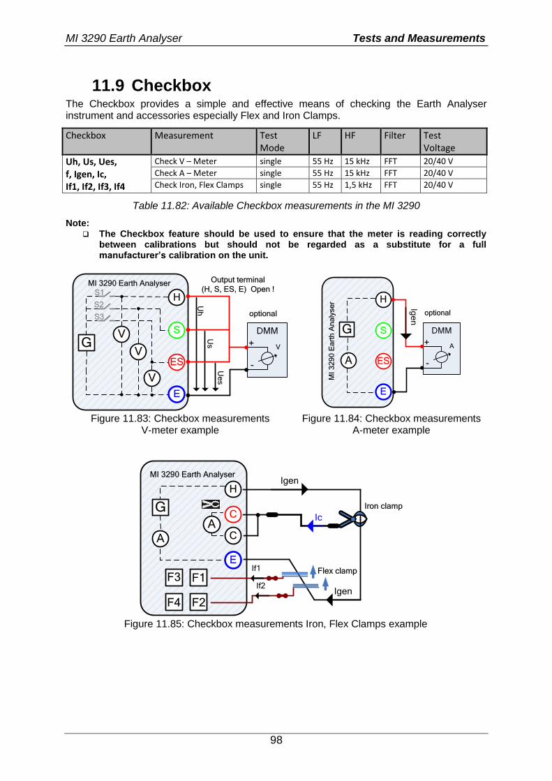
MI 3290 Earth Analyser Tests and Measurements
98
11.9 Checkbox The Checkbox provides a simple and effective means of checking the Earth Analyser instrument and accessories especially Flex and Iron Clamps.
Checkbox Measurement Test Mode
LF HF Filter Test Voltage
Uh, Us, Ues, f, Igen, Ic, If1, If2, If3, If4
Check V – Meter single 55 Hz 15 kHz FFT 20/40 V
Check A – Meter single 55 Hz 15 kHz FFT 20/40 V
Check Iron, Flex Clamps single 55 Hz 1,5 kHz FFT 20/40 V
Table 11.82: Available Checkbox measurements in the MI 3290
Note: The Checkbox feature should be used to ensure that the meter is reading correctly
between calibrations but should not be regarded as a substitute for a full manufacturer’s calibration on the unit.
Us
U
h
H
S
ES
E
MI 3290 Earth Analyser
GV
V
V
Output terminal
(H, S, ES, E) Open !S1
S2
S3
DMM
+
-
V
optional
Ue
s
H
S
ES
E
MI
32
90
Ea
rth
An
aly
se
rG
A
DMM
+
-
A
Ige
n
optional
Figure 11.83: Checkbox measurements V-meter example
Figure 11.84: Checkbox measurements A-meter example
F4 F2
F3 F1Flex clampIf1
H
E
MI 3290 Earth Analyser
G
A
Igen
AC
C Ic
Igen If2
Iron clamp
Figure 11.85: Checkbox measurements Iron, Flex Clamps example
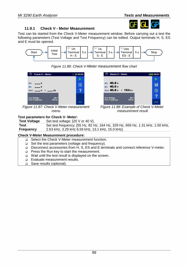
MI 3290 Earth Analyser Tests and Measurements
99
11.9.1 Check V - Meter Measurement
Test can be started from the Check V-Meter measurement window. Before carrying out a test the following parameters (Test Voltage and Test Frequency) can be edited. Output terminals H, S, ES and E must be opened.
Start
Uh
Terminal
H - E
Us
Terminal
S - E
Ues
Terminal
ES - E
Stop5 s 5 s 5 sInitial
Test
S1 S2 S3
Figure 11.86: Check V-Meter measurement flow chart
Figure 11.87: Check V-Meter measurement
menu Figure 11.88: Example of Check V-Meter
measurement result
Test parameters for Check V- Meter: Test Voltage Set test voltage: [20 V or 40 V].
Test Frequency
Set test frequency: [55 Hz, 82 Hz, 164 Hz, 329 Hz, 659 Hz, 1.31 kHz, 1.50 kHz, 2.63 kHz, 3.29 kHz 6.59 kHz, 13.1 kHz, 15.0 kHz].
Check V-Meter Measurement procedure:
Select the Check V-Meter measurement function. Set the test parameters (voltage and frequency). Disconnect accessories from H, S, ES and E terminals and connect reference V-meter. Press the Run key to start the measurement. Wait until the test result is displayed on the screen. Evaluate measurement results. Save results (optional).
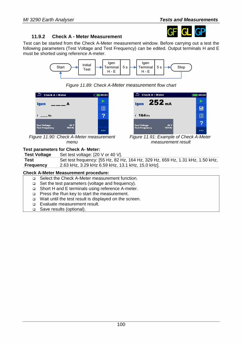
MI 3290 Earth Analyser Tests and Measurements
100
11.9.2 Check A - Meter Measurement
Test can be started from the Check A-Meter measurement window. Before carrying out a test the following parameters (Test Voltage and Test Frequency) can be edited. Output terminals H and E must be shorted using reference A-meter.
Start
Igen
Terminal
H - E
Igen
Terminal
H - E
Stop5 s 5 sInitial
Test
Figure 11.89: Check A-Meter measurement flow chart
Figure 11.90: Check A-Meter measurement
menu Figure 11.91: Example of Check A-Meter
measurement result
Test parameters for Check A- Meter: Test Voltage Set test voltage: [20 V or 40 V].
Test Frequency
Set test frequency: [55 Hz, 82 Hz, 164 Hz, 329 Hz, 659 Hz, 1.31 kHz, 1.50 kHz, 2.63 kHz, 3.29 kHz 6.59 kHz, 13.1 kHz, 15.0 kHz].
Check A-Meter Measurement procedure:
Select the Check A-Meter measurement function. Set the test parameters (voltage and frequency). Short H and E terminals using reference A-meter. Press the Run key to start the measurement. Wait until the test result is displayed on the screen. Evaluate measurement result. Save results (optional).
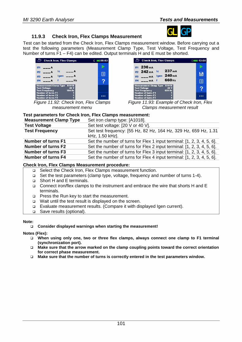
MI 3290 Earth Analyser Tests and Measurements
101
11.9.3 Check Iron, Flex Clamps Measurement
Test can be started from the Check Iron, Flex Clamps measurement window. Before carrying out a test the following parameters (Measurement Clamp Type, Test Voltage, Test Frequency and Number of turns F1 – F4) can be edited. Output terminals H and E must be shorted.
Figure 11.92: Check Iron, Flex Clamps
measurement menu Figure 11.93: Example of Check Iron, Flex
Clamps measurement result
Test parameters for Check Iron, Flex Clamps measurement: Measurement Clamp Type Set iron clamp type: [A1018].
Test Voltage Set test voltage: [20 V or 40 V].
Test Frequency Set test frequency: [55 Hz, 82 Hz, 164 Hz, 329 Hz, 659 Hz, 1.31 kHz, 1.50 kHz].
Number of turns F1 Set the number of turns for Flex 1 input terminal: [1, 2, 3, 4, 5, 6].
Number of turns F2 Set the number of turns for Flex 2 input terminal: [1, 2, 3, 4, 5, 6].
Number of turns F3 Set the number of turns for Flex 3 input terminal: [1, 2, 3, 4, 5, 6].
Number of turns F4 Set the number of turns for Flex 4 input terminal: [1, 2, 3, 4, 5, 6].
Check Iron, Flex Clamps Measurement procedure:
Select the Check Iron, Flex Clamps measurement function. Set the test parameters (clamp type, voltage, frequency and number of turns 1-4). Short H and E terminals. Connect iron/flex clamps to the instrument and embrace the wire that shorts H and E
terminals. Press the Run key to start the measurement. Wait until the test result is displayed on the screen. Evaluate measurement results. (Compare it with displayed Igen current). Save results (optional).
Note:
Consider displayed warnings when starting the measurement!
Notes (Flex): When using only one, two or three flex clamps, always connect one clamp to F1 terminal
(synchronization port). Make sure that the arrow marked on the clamp coupling points toward the correct orientation
for correct phase measurement. Make sure that the number of turns is correctly entered in the test parameters window.
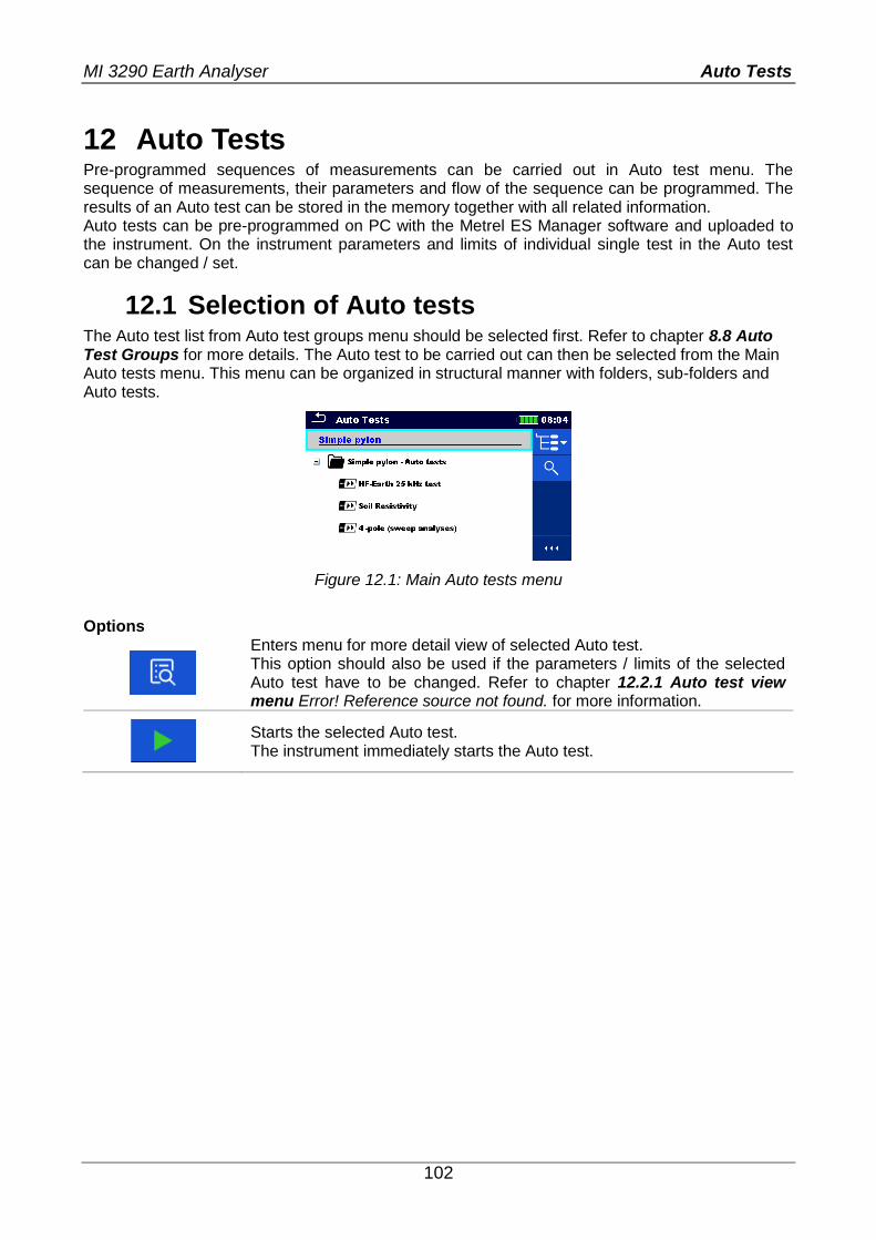
MI 3290 Earth Analyser Auto Tests
102
12 Auto Tests Pre-programmed sequences of measurements can be carried out in Auto test menu. The sequence of measurements, their parameters and flow of the sequence can be programmed. The results of an Auto test can be stored in the memory together with all related information. Auto tests can be pre-programmed on PC with the Metrel ES Manager software and uploaded to the instrument. On the instrument parameters and limits of individual single test in the Auto test can be changed / set.
12.1 Selection of Auto tests
The Auto test list from Auto test groups menu should be selected first. Refer to chapter 8.8 Auto Test Groups for more details. The Auto test to be carried out can then be selected from the Main Auto tests menu. This menu can be organized in structural manner with folders, sub-folders and Auto tests.
Figure 12.1: Main Auto tests menu
Options
Enters menu for more detail view of selected Auto test. This option should also be used if the parameters / limits of the selected Auto test have to be changed. Refer to chapter 12.2.1 Auto test view menu Error! Reference source not found. for more information.
Starts the selected Auto test. The instrument immediately starts the Auto test.

MI 3290 Earth Analyser Auto Tests
103
12.2 Organization of Auto tests An Auto test is divided into three phases:
Before starting the first test the Auto test view menu is shown (unless it was started directly from the Main Auto tests menu). Parameters and limits of individual measurements can be set in this menu.
During the execution phase of an Auto test, pre-programmed single tests are carried out. The sequence of single tests is controlled by pre-programmed flow commands.
After the test sequence is finished the Auto test result menu is shown. Details of individual tests can be viewed and the results can be saved to Memory organizer.
12.2.1 Auto test view menu
In the Auto test view menu, the header and the single tests of selected Auto test are displayed. The header contains the name and description of the Auto test. Before starting the Auto test, test parameters / limits of individual measurements can be changed. Auto test view menu (header is selected)
Name of Auto Test Description of Auto Test
Header
Single
Test
Options
Figure 12.2: Auto test view menu – header selected
Options
Starts the Auto test.
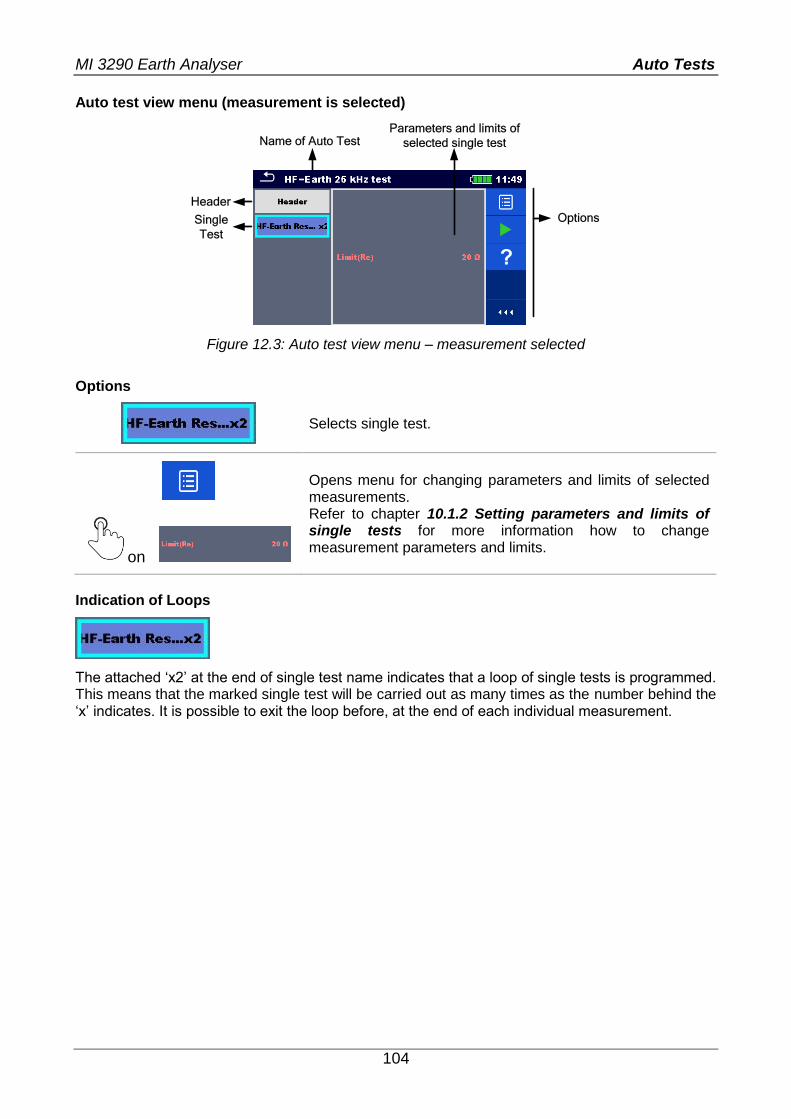
MI 3290 Earth Analyser Auto Tests
104
Auto test view menu (measurement is selected)
Name of Auto TestParameters and limits of
selected single test
Header
Single
Test
Options
Figure 12.3: Auto test view menu – measurement selected
Options
Selects single test.
on
Opens menu for changing parameters and limits of selected measurements. Refer to chapter 10.1.2 Setting parameters and limits of single tests for more information how to change measurement parameters and limits.
Indication of Loops
The attached ‘x2’ at the end of single test name indicates that a loop of single tests is programmed. This means that the marked single test will be carried out as many times as the number behind the ‘x’ indicates. It is possible to exit the loop before, at the end of each individual measurement.
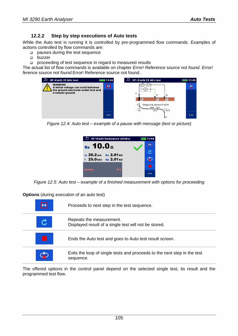
MI 3290 Earth Analyser Auto Tests
105
12.2.2 Step by step executions of Auto tests
While the Auto test is running it is controlled by pre-programmed flow commands. Examples of actions controlled by flow commands are:
pauses during the test sequence buzzer proceeding of test sequence in regard to measured results
The actual list of flow commands is available on chapter Error! Reference source not found. Error! ference source not found.Error! Reference source not found..
Figure 12.4: Auto test – example of a pause with message (text or picture)
Figure 12.5: Auto test – example of a finished measurement with options for proceeding
Options (during execution of an auto test)
Proceeds to next step in the test sequence.
Repeats the measurement. Displayed result of a single test will not be stored.
Ends the Auto test and goes to Auto test result screen.
Exits the loop of single tests and proceeds to the next step in the test sequence.
The offered options in the control panel depend on the selected single test, its result and the programmed test flow.
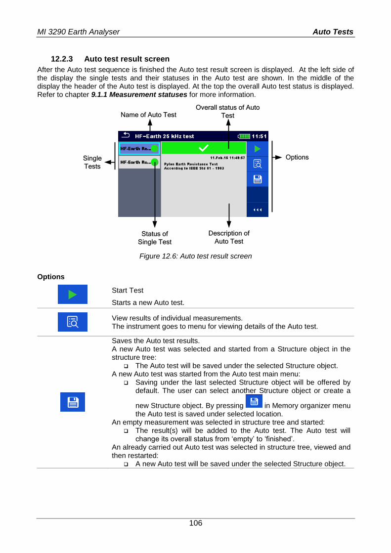
MI 3290 Earth Analyser Auto Tests
106
12.2.3 Auto test result screen
After the Auto test sequence is finished the Auto test result screen is displayed. At the left side of the display the single tests and their statuses in the Auto test are shown. In the middle of the display the header of the Auto test is displayed. At the top the overall Auto test status is displayed. Refer to chapter 9.1.1 Measurement statuses for more information.
Name of Auto TestOverall status of Auto
Test
Single
Tests
Options
Description of
Auto TestStatus of
Single Test
Figure 12.6: Auto test result screen
Options
Start Test
Starts a new Auto test.
View results of individual measurements. The instrument goes to menu for viewing details of the Auto test.
Saves the Auto test results. A new Auto test was selected and started from a Structure object in the structure tree:
The Auto test will be saved under the selected Structure object. A new Auto test was started from the Auto test main menu:
Saving under the last selected Structure object will be offered by default. The user can select another Structure object or create a
new Structure object. By pressing in Memory organizer menu the Auto test is saved under selected location.
An empty measurement was selected in structure tree and started: The result(s) will be added to the Auto test. The Auto test will
change its overall status from ‘empty’ to ‘finished’. An already carried out Auto test was selected in structure tree, viewed and then restarted:
A new Auto test will be saved under the selected Structure object.
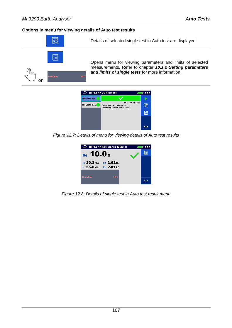
MI 3290 Earth Analyser Auto Tests
107
Options in menu for viewing details of Auto test results
Details of selected single test in Auto test are displayed.
on
Opens menu for viewing parameters and limits of selected measurements. Refer to chapter 10.1.2 Setting parameters and limits of single tests for more information.
Figure 12.7: Details of menu for viewing details of Auto test results
Figure 12.8: Details of single test in Auto test result menu
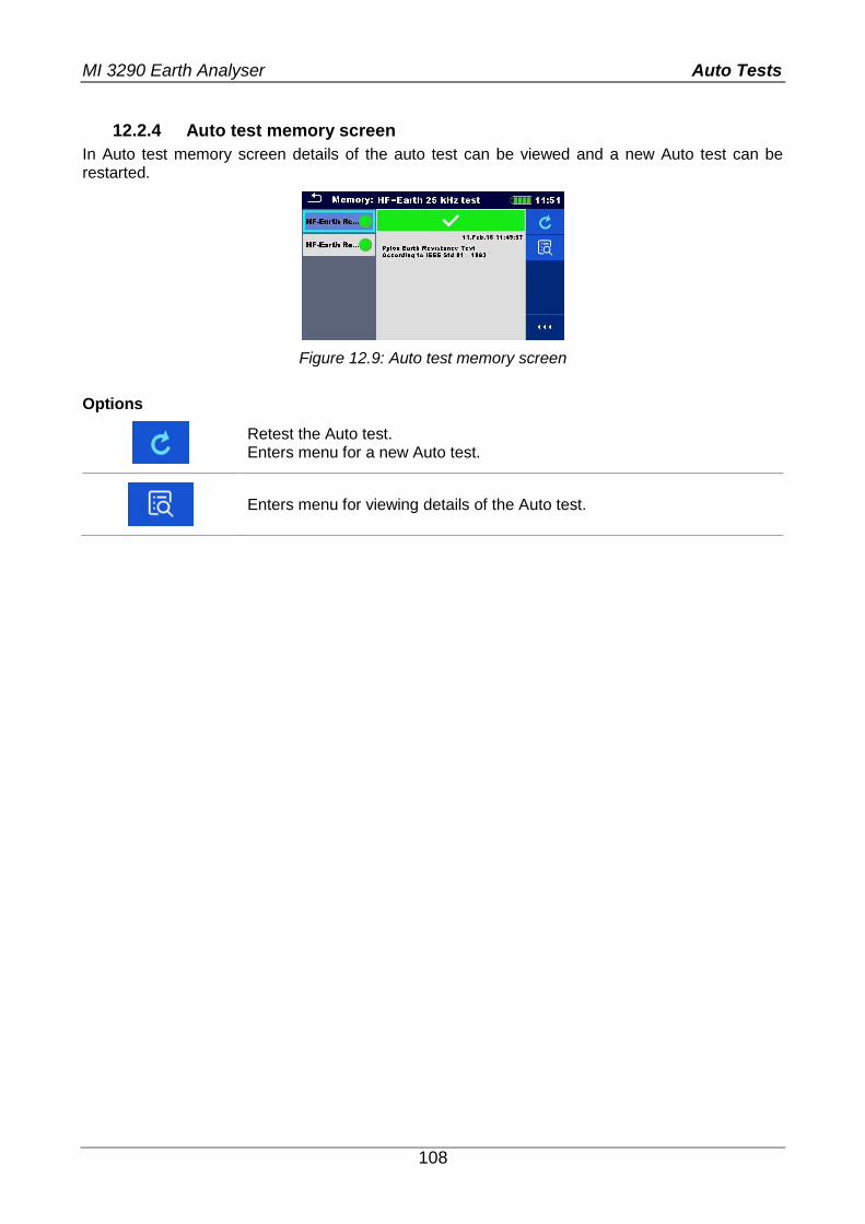
MI 3290 Earth Analyser Auto Tests
108
12.2.4 Auto test memory screen
In Auto test memory screen details of the auto test can be viewed and a new Auto test can be restarted.
Figure 12.9: Auto test memory screen
Options
Retest the Auto test. Enters menu for a new Auto test.
Enters menu for viewing details of the Auto test.
MI 3290 Earth Analyser Communication
109
13 Communication The instrument can communicate with the Metrel ES Manager PC software. The following action is supported:
Saved results and Tree structure from Memory organizer can be downloaded and stored to a PC.
Tree structure and Auto tests from Metrel ES Manager PC software can be uploaded to the instrument.
Metrel ES Manager is PC software running on Windows 7, Windows 8, Windows 8.1 and Windows 10. There are two communication interfaces available on the instrument: USB and Bluetooth. How to establish an USB link:
Connect a PC USB port to the instrument USB connector using the USB interface cable.
Switch on the PC and the instrument. Run the Metrel ES Manager software. Set the desired communication port. (COM port is identified as “USB Serial Port”.) If not visible, make sure to install the correct USB driver (see notes). The instrument is prepared to communicate with the PC over USB.
Bluetooth communication The internal Bluetooth module enables easy communication via Bluetooth with PC and Android devices. How to configure a Bluetooth link between instrument and PC:
Switch On the instrument. On PC configure a Standard Serial Port to enable communication over Bluetooth link
between instrument and PC. Usually no code for pairing the devices is needed. Run the Metrel ES Manager software. Set the configured communication port. The instrument is prepared to communicate with the PC over Bluetooth.
Notes:
USB drivers should be installed on PC before using the USB interface. Refer to USB installation instructions available on installation CD or download the drivers from the http://www.ftdichip.com website (MI 3290 is using the FT230X chip).
The name of correctly configured Bluetooth device must consist of the instrument type plus serial number, eg. MI 3290-12345678I.
Bluetooth communication device pairing code is NNNN.
MI 3290 Earth Analyser Maintenance
110
14 Maintenance Unauthorized persons are not allowed to open the Earth Analyser instrument. There are no user replaceable components inside the instrument. Batteries can only be replaced with certified ones and only by authorized persons.
14.1 Cleaning No special maintenance is required for the housing. To clean the surface of the instrument, use a soft cloth slightly moistened with soapy water or alcohol. Then leave the instrument to dry totally before use. Warnings:
Do not use liquids based on petrol or hydrocarbons! Do not spill cleaning liquid over the instrument!
14.2 Periodic calibration It is essential that the test instrument is regularly calibrated in order that the technical specification listed in this manual is guaranteed. We recommend an annual calibration. Only an authorized technical person can do the calibration. Please contact your dealer for further information.
14.3 Service For repairs under warranty, or at any other time, please contact your distributor.
14.4 Upgrading the instrument The instrument can be upgraded from a PC via the USB communication port. This enables to keep the instrument up to date even if the standards or regulations change. The firmware upgrade requires internet access and can be carried out from the Metrel ES Manager software with a help of special upgrading software – FlashMe which will guide you through the upgrading procedure. For more information, refer to Metrel ES Manager Help file. Note:
See chapter 13 Communication for details on USB driver installation.
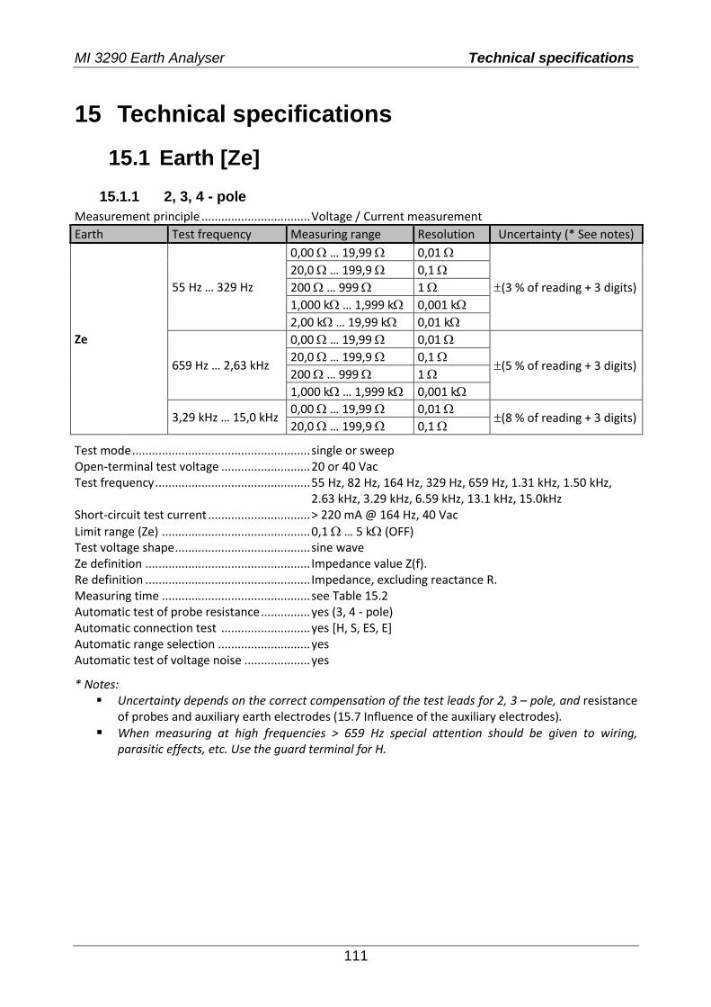
MI 3290 Earth Analyser Technical specifications
111
15 Technical specifications
15.1 Earth [Ze]
15.1.1 2, 3, 4 - pole
Measurement principle ................................. Voltage / Current measurement
Earth Test frequency Measuring range Resolution Uncertainty (* See notes)
Ze
55 Hz … 329 Hz
0,00 … 19,99 0,01
(3 % of reading + 3 digits)
20,0 … 199,9 0,1
200 … 999 1
1,000 k … 1,999 k 0,001 k
2,00 k … 19,99 k 0,01 k
659 Hz … 2,63 kHz
0,00 … 19,99 0,01
(5 % of reading + 3 digits) 20,0 … 199,9 0,1
200 … 999 1
1,000 k … 1,999 k 0,001 k
3,29 kHz … 15,0 kHz 0,00 … 19,99 0,01
(8 % of reading + 3 digits) 20,0 … 199,9 0,1
Test mode ...................................................... single or sweep Open-terminal test voltage ........................... 20 or 40 Vac Test frequency ............................................... 55 Hz, 82 Hz, 164 Hz, 329 Hz, 659 Hz, 1.31 kHz, 1.50 kHz, 2.63 kHz, 3.29 kHz, 6.59 kHz, 13.1 kHz, 15.0kHz Short-circuit test current ............................... > 220 mA @ 164 Hz, 40 Vac
Limit range (Ze) ............................................. 0,1 … 5 k (OFF) Test voltage shape ......................................... sine wave Ze definition .................................................. Impedance value Z(f). Re definition .................................................. Impedance, excluding reactance R. Measuring time ............................................. see Table 15.2 Automatic test of probe resistance ............... yes (3, 4 - pole) Automatic connection test ........................... yes [H, S, ES, E] Automatic range selection ............................ yes Automatic test of voltage noise .................... yes
* Notes: Uncertainty depends on the correct compensation of the test leads for 2, 3 – pole, and resistance
of probes and auxiliary earth electrodes (15.7 Influence of the auxiliary electrodes).
When measuring at high frequencies > 659 Hz special attention should be given to wiring, parasitic effects, etc. Use the guard terminal for H.

MI 3290 Earth Analyser Technical specifications
112
15.1.2 Selective (Iron Clamp)
Measurement principle: ............................... Voltage / Current (external Iron Clamp) measurement
Selective Earth Impedance
Test frequency Measuring range Resolution Uncertainty
Zsel
55 Hz … 329 Hz
0,00 … 19,99 0,01
(8 % of reading + 3 digits)
20,0 … 199,9 0,1
200 … 999 1
1,000 k … 1,999 k 0,001 k
2,00 k … 19,99 k 0,01 k
659 Hz … 1,50 kHz
0,00 … 19,99 0,01
20,0 … 199,9 0,1
200 … 999 1
1,000 k … 1,999 k 0,001 k
Test mode ...................................................... single or sweep Open-terminal test voltage ........................... 40 Vac Test frequency ............................................... 55 Hz, 82 Hz, 164 Hz, 329 Hz, 659 Hz, 1.31 kHz, 1.50 kHz Short-circuit test current ............................... > 220 mA @ 164 Hz, 40 Vac
Limit range (Zsel) .......................................... 0,1 … 5 k (OFF) Test voltage shape ......................................... sine wave Zsel definition ................................................ Impedance value Z(f). Measuring time ............................................. see Table 15.2 Measurement Clamp type ............................ A1018 Automatic test of probe resistance ............... yes Automatic connection test ........................... yes [H, S, ES, E] Automatic range selection ............................ yes Automatic test of voltage noise .................... yes Low clamp current indication ........................ yes [Ic]
Typical output current ie vs Auxiliary earth probe resistance Rc
2, 3, 4 - pole, Selective (Iron, Flex clamps), Wenner and Schlumberger method
0
50
100
150
200
250
300
1 10 100 1000 10000Rc [Ω]
ie [
mA
]
55 Hz
164 Hz
1,31 kHz
3,29 kHz
6,59 kHz
13,1 kHz
15,0 kHz
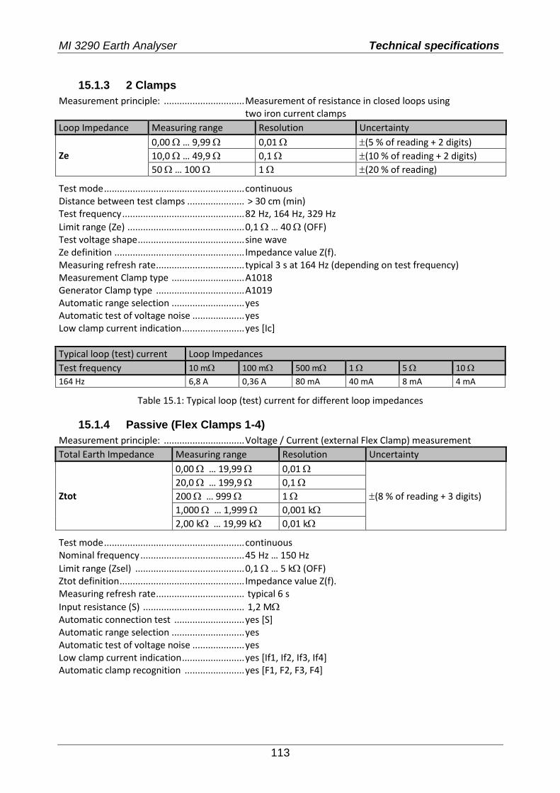
MI 3290 Earth Analyser Technical specifications
113
15.1.3 2 Clamps
Measurement principle: ............................... Measurement of resistance in closed loops using two iron current clamps
Loop Impedance Measuring range Resolution Uncertainty
Ze
0,00 … 9,99 0,01 (5 % of reading + 2 digits)
10,0 … 49,9 0,1 (10 % of reading + 2 digits)
50 … 100 1 (20 % of reading)
Test mode ...................................................... continuous Distance between test clamps ...................... > 30 cm (min) Test frequency ............................................... 82 Hz, 164 Hz, 329 Hz
Limit range (Ze) ............................................. 0,1 … 40 (OFF) Test voltage shape ......................................... sine wave Ze definition .................................................. Impedance value Z(f). Measuring refresh rate .................................. typical 3 s at 164 Hz (depending on test frequency) Measurement Clamp type ............................ A1018 Generator Clamp type .................................. A1019 Automatic range selection ............................ yes Automatic test of voltage noise .................... yes Low clamp current indication ........................ yes [Ic]
Typical loop (test) current Loop Impedances
Test frequency 10 m 100 m 500 m 1 5 10
164 Hz 6,8 A 0,36 A 80 mA 40 mA 8 mA 4 mA
Table 15.1: Typical loop (test) current for different loop impedances
15.1.4 Passive (Flex Clamps 1-4)
Measurement principle: ............................... Voltage / Current (external Flex Clamp) measurement
Total Earth Impedance Measuring range Resolution Uncertainty
Ztot
0,00 … 19,99 0,01
(8 % of reading + 3 digits)
20,0 … 199,9 0,1
200 … 999 1
1,000 … 1,999 0,001 k
2,00 k … 19,99 k 0,01 k
Test mode ...................................................... continuous Nominal frequency ........................................ 45 Hz … 150 Hz
Limit range (Zsel) .......................................... 0,1 … 5 k (OFF) Ztot definition ................................................ Impedance value Z(f). Measuring refresh rate .................................. typical 6 s
Input resistance (S) ....................................... 1,2 M Automatic connection test ........................... yes [S] Automatic range selection ............................ yes Automatic test of voltage noise .................... yes Low clamp current indication ........................ yes [If1, If2, If3, If4] Automatic clamp recognition ....................... yes [F1, F2, F3, F4]
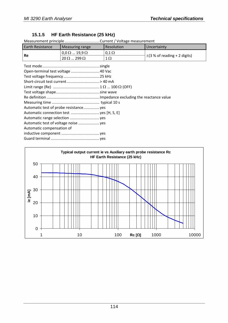
MI 3290 Earth Analyser Technical specifications
114
15.1.5 HF Earth Resistance (25 kHz)
Measurement principle ................................. Current / Voltage measurement
Earth Resistance Measuring range Resolution Uncertainty
Re 0,0 … 19,9 0,1
(3 % of reading + 2 digits) 20 … 299 1
Test mode ...................................................... single Open-terminal test voltage ........................... 40 Vac Test voltage frequency .................................. 25 kHz Short-circuit test current ............................... > 40 mA
Limit range (Re) ............................................ 1 … 100 (OFF) Test voltage shape ......................................... sine wave Re definition .................................................. Impedance excluding the reactance value Measuring time ............................................. typical 10 s Automatic test of probe resistance ............... yes Automatic connection test ........................... yes [H, S, E] Automatic range selection ............................ yes Automatic test of voltage noise .................... yes Automatic compensation of inductive component .................................... yes Guard terminal .............................................. yes
Typical output current ie vs Auxiliary earth probe resistance Rc
HF Earth Resistance (25 kHz)
0
10
20
30
40
50
1 10 100 1000 10000Rc [Ω]
ie [
mA
]
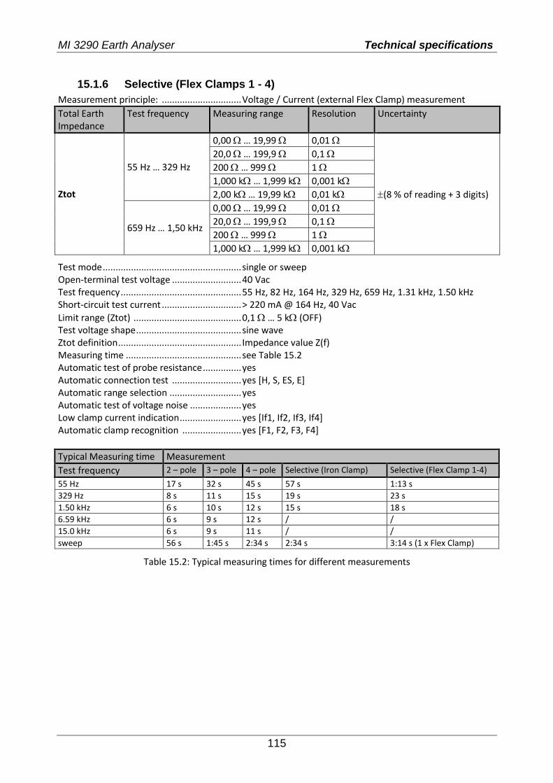
MI 3290 Earth Analyser Technical specifications
115
15.1.6 Selective (Flex Clamps 1 - 4)
Measurement principle: ............................... Voltage / Current (external Flex Clamp) measurement
Total Earth Impedance
Test frequency Measuring range Resolution Uncertainty
Ztot
55 Hz … 329 Hz
0,00 … 19,99 0,01
(8 % of reading + 3 digits)
20,0 … 199,9 0,1
200 … 999 1
1,000 k … 1,999 k 0,001 k
2,00 k … 19,99 k 0,01 k
659 Hz … 1,50 kHz
0,00 … 19,99 0,01
20,0 … 199,9 0,1
200 … 999 1
1,000 k … 1,999 k 0,001 k
Test mode ...................................................... single or sweep Open-terminal test voltage ........................... 40 Vac Test frequency ............................................... 55 Hz, 82 Hz, 164 Hz, 329 Hz, 659 Hz, 1.31 kHz, 1.50 kHz Short-circuit test current ............................... > 220 mA @ 164 Hz, 40 Vac
Limit range (Ztot) .......................................... 0,1 … 5 k (OFF) Test voltage shape ......................................... sine wave Ztot definition ................................................ Impedance value Z(f) Measuring time ............................................. see Table 15.2 Automatic test of probe resistance ............... yes Automatic connection test ........................... yes [H, S, ES, E] Automatic range selection ............................ yes Automatic test of voltage noise .................... yes Low clamp current indication ........................ yes [If1, If2, If3, If4] Automatic clamp recognition ....................... yes [F1, F2, F3, F4]
Typical Measuring time Measurement
Test frequency 2 – pole 3 – pole 4 – pole Selective (Iron Clamp) Selective (Flex Clamp 1-4)
55 Hz 17 s 32 s 45 s 57 s 1:13 s
329 Hz 8 s 11 s 15 s 19 s 23 s
1.50 kHz 6 s 10 s 12 s 15 s 18 s
6.59 kHz 6 s 9 s 12 s / /
15.0 kHz 6 s 9 s 11 s / /
sweep 56 s 1:45 s 2:34 s 2:34 s 3:14 s (1 x Flex Clamp)
Table 15.2: Typical measuring times for different measurements
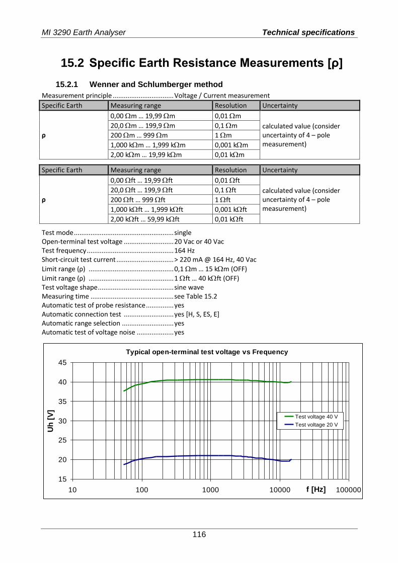
MI 3290 Earth Analyser Technical specifications
116
15.2 Specific Earth Resistance Measurements [ρ]
15.2.1 Wenner and Schlumberger method
Measurement principle ................................. Voltage / Current measurement
Specific Earth Measuring range Resolution Uncertainty
ρ
0,00 m … 19,99 m 0,01 m
calculated value (consider uncertainty of 4 – pole measurement)
20,0 m … 199,9 m 0,1 m
200 m … 999 m 1 m
1,000 km … 1,999 km 0,001 km
2,00 km … 19,99 km 0,01 km
Specific Earth Measuring range Resolution Uncertainty
ρ
0,00 ft … 19,99 ft 0,01 ft
calculated value (consider uncertainty of 4 – pole measurement)
20,0 ft … 199,9 ft 0,1 ft
200 ft … 999 ft 1 ft
1,000 kft … 1,999 kft 0,001 kft
2,00 kft … 59,99 kft 0,01 kft
Test mode ...................................................... single Open-terminal test voltage ........................... 20 Vac or 40 Vac Test frequency ............................................... 164 Hz Short-circuit test current ............................... > 220 mA @ 164 Hz, 40 Vac
Limit range (ρ) .............................................. 0,1 m … 15 km (OFF)
Limit range (ρ) .............................................. 1 ft … 40 kft (OFF) Test voltage shape ......................................... sine wave Measuring time ............................................. see Table 15.2 Automatic test of probe resistance ............... yes Automatic connection test ........................... yes [H, S, ES, E] Automatic range selection ............................ yes Automatic test of voltage noise .................... yes
Typical open-terminal test voltage vs Frequency
15
20
25
30
35
40
45
10 100 1000 10000 100000f [Hz]
Uh
[V
]
Test voltage 40 V
Test voltage 20 V
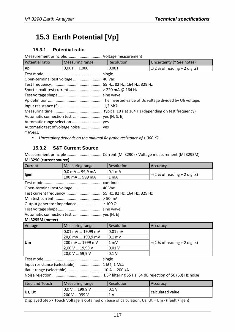
MI 3290 Earth Analyser Technical specifications
117
15.3 Earth Potential [Vp]
15.3.1 Potential ratio
Measurement principle: ............................... Voltage measurement
Potential ratio Measuring range Resolution Uncertainty (* See notes)
Vp 0,001 … 1,000 0,001 (2 % of reading + 2 digits)
Test mode ...................................................... single Open-terminal test voltage ........................... 40 Vac Test frequency ............................................... 55 Hz, 82 Hz, 164 Hz, 329 Hz Short-circuit test current ............................... > 220 mA @ 164 Hz Test voltage shape ......................................... sine wave Vp definition .................................................. The inverted value of Us voltage divided by Uh voltage.
Input resistance (S) ....................................... 1,2 M Measuring time ............................................. typical 10 s at 164 Hz (depending on test frequency) Automatic connection test ........................... yes [H, S, E] Automatic range selection ............................ yes Automatic test of voltage noise .................... yes * Notes:
Uncertainty depends on the minimal Rc probe resistance of > 300 .
15.3.2 S&T Current Source
Measurement principle ................................. Current (MI 3290) / Voltage measurement (MI 3295M) MI 3290 (current source)
Current Measuring range Resolution Accuracy
Igen 0,0 mA … 99,9 mA 0,1 mA
(2 % of reading + 2 digits) 100 mA … 999 mA 1 mA
Test mode ...................................................... continues Open-terminal test voltage ........................... 40 Vac Test current frequency .................................. 55 Hz, 82 Hz, 164 Hz, 329 Hz Min test current............................................. > 50 mA Output generator impedance........................ ~ 100 Ω Test voltage shape ......................................... sine wave Automatic connection test ........................... yes [H, E] MI 3295M (meter)
Voltage Measuring range Resolution Accuracy
Um
0,01 mV … 19,99 mV 0,01 mV
(2 % of reading + 2 digits)
20,0 mV … 199,9 mV 0,1 mV
200 mV … 1999 mV 1 mV
2,00 V … 19,99 V 0,01 V
20,0 V … 59,9 V 0,1 V
Test mode ...................................................... single
Input resistance (selectable) ........................ 1 k, 1 M Ifault range (selectable) ................................. 10 A … 200 kA Noise rejection .............................................. DSP filtering 55 Hz, 64 dB rejection of 50 (60) Hz noise
Step and Touch Measuring range Resolution Accuracy
Us, Ut 0,0 V … 199,9 V 0,1 V
calculated value 200 V … 999 V 1 V
Displayed Step / Touch Voltage is obtained on base of calculation: Us, Ut = Um ∙ (Ifault / Igen)
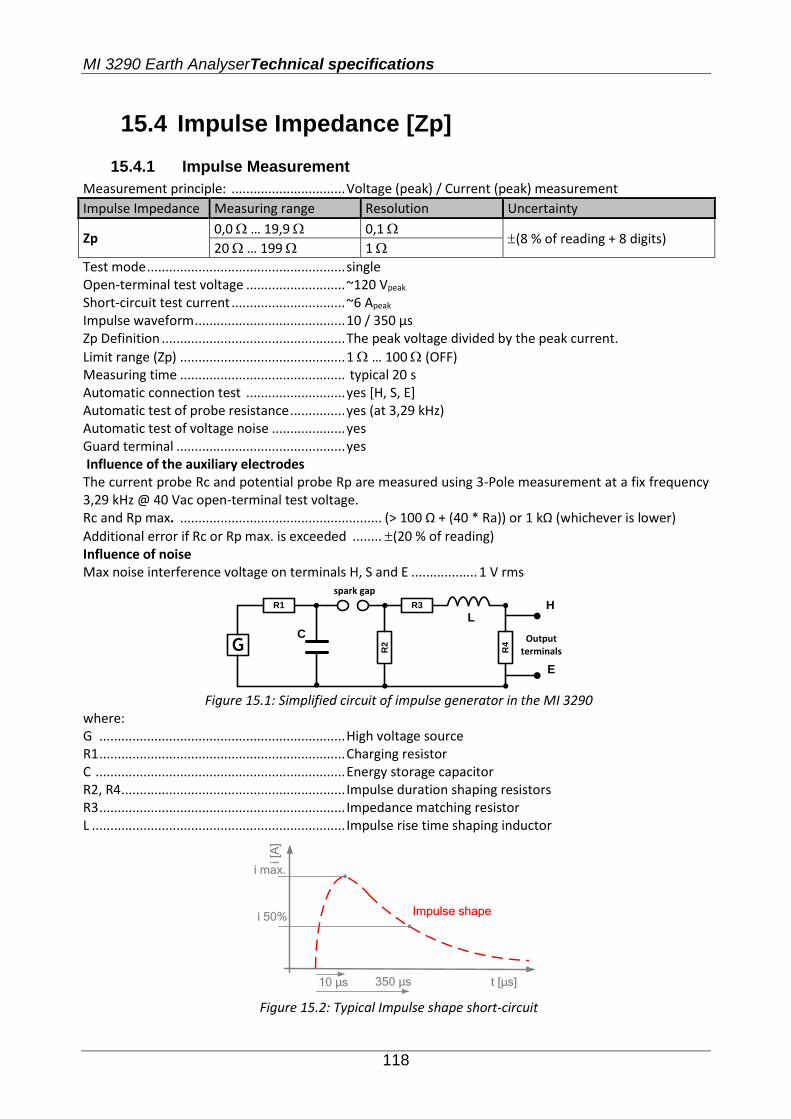
MI 3290 Earth AnalyserTechnical specifications
118
15.4 Impulse Impedance [Zp]
15.4.1 Impulse Measurement
Measurement principle: ............................... Voltage (peak) / Current (peak) measurement
Impulse Impedance Measuring range Resolution Uncertainty
Zp 0,0 … 19,9 0,1
(8 % of reading + 8 digits) 20 … 199 1
Test mode ...................................................... single Open-terminal test voltage ........................... ~120 Vpeak Short-circuit test current ............................... ~6 Apeak
Impulse waveform ......................................... 10 / 350 µs Zp Definition .................................................. The peak voltage divided by the peak current.
Limit range (Zp) ............................................. 1 … 100 (OFF) Measuring time ............................................. typical 20 s Automatic connection test ........................... yes [H, S, E] Automatic test of probe resistance ............... yes (at 3,29 kHz) Automatic test of voltage noise .................... yes Guard terminal .............................................. yes Influence of the auxiliary electrodes The current probe Rc and potential probe Rp are measured using 3-Pole measurement at a fix frequency 3,29 kHz @ 40 Vac open-terminal test voltage. Rc and Rp max. ....................................................... (> 100 Ω + (40 * Ra)) or 1 kΩ (whichever is lower)
Additional error if Rc or Rp max. is exceeded ........ (20 % of reading) Influence of noise Max noise interference voltage on terminals H, S and E .................. 1 V rms
R1 R3
R4G R2
spark gap
C
L
Output terminals
H
E
Figure 15.1: Simplified circuit of impulse generator in the MI 3290
where: G ................................................................... High voltage source R1 ................................................................... Charging resistor C .................................................................... Energy storage capacitor R2, R4 ............................................................. Impulse duration shaping resistors R3 ................................................................... Impedance matching resistor L ..................................................................... Impulse rise time shaping inductor
t [µs]
i [A
]
Impulse shape
i max.
10 µs
i 50%
350 µs
Figure 15.2: Typical Impulse shape short-circuit
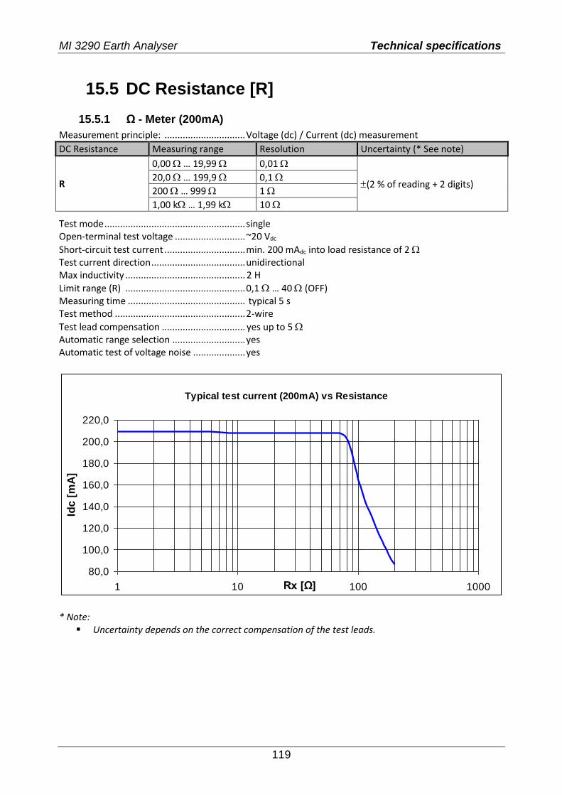
MI 3290 Earth Analyser Technical specifications
119
15.5 DC Resistance [R]
15.5.1 Ω - Meter (200mA)
Measurement principle: ............................... Voltage (dc) / Current (dc) measurement
DC Resistance Measuring range Resolution Uncertainty (* See note)
R
0,00 … 19,99 0,01
(2 % of reading + 2 digits) 20,0 … 199,9 0,1
200 … 999 1
1,00 k … 1,99 k 10
Test mode ...................................................... single Open-terminal test voltage ........................... ~20 Vdc
Short-circuit test current ............................... min. 200 mAdc into load resistance of 2 Test current direction .................................... unidirectional Max inductivity .............................................. 2 H
Limit range (R) .............................................. 0,1 … 40 (OFF) Measuring time ............................................. typical 5 s Test method .................................................. 2-wire
Test lead compensation ................................ yes up to 5 Automatic range selection ............................ yes Automatic test of voltage noise .................... yes
Typical test current (200mA) vs Resistance
80,0
100,0
120,0
140,0
160,0
180,0
200,0
220,0
1 10 100 1000Rx [Ω]
Idc [
mA
]
* Note:
Uncertainty depends on the correct compensation of the test leads.
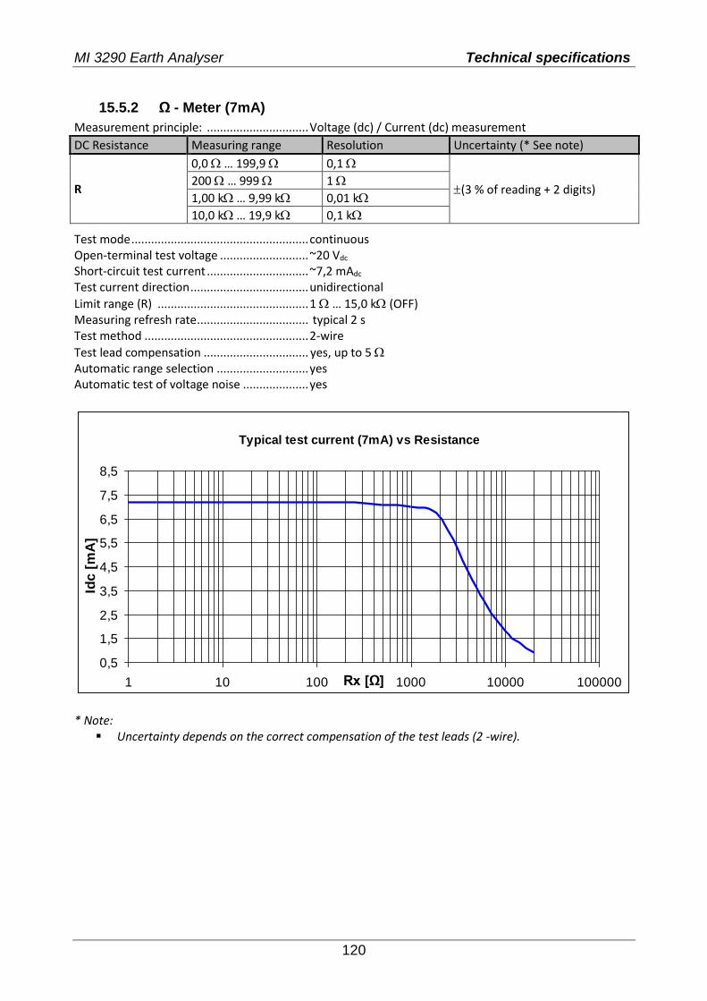
MI 3290 Earth Analyser Technical specifications
120
15.5.2 Ω - Meter (7mA)
Measurement principle: ............................... Voltage (dc) / Current (dc) measurement
DC Resistance Measuring range Resolution Uncertainty (* See note)
R
0,0 … 199,9 0,1
(3 % of reading + 2 digits) 200 … 999 1
1,00 k … 9,99 k 0,01 k
10,0 k … 19,9 k 0,1 k
Test mode ...................................................... continuous Open-terminal test voltage ........................... ~20 Vdc Short-circuit test current ............................... ~7,2 mAdc
Test current direction .................................... unidirectional
Limit range (R) .............................................. 1 … 15,0 k (OFF) Measuring refresh rate .................................. typical 2 s Test method .................................................. 2-wire
Test lead compensation ................................ yes, up to 5 Automatic range selection ............................ yes Automatic test of voltage noise .................... yes
Typical test current (7mA) vs Resistance
0,5
1,5
2,5
3,5
4,5
5,5
6,5
7,5
8,5
1 10 100 1000 10000 100000Rx [Ω]
Idc [
mA
]
* Note:
Uncertainty depends on the correct compensation of the test leads (2 -wire).
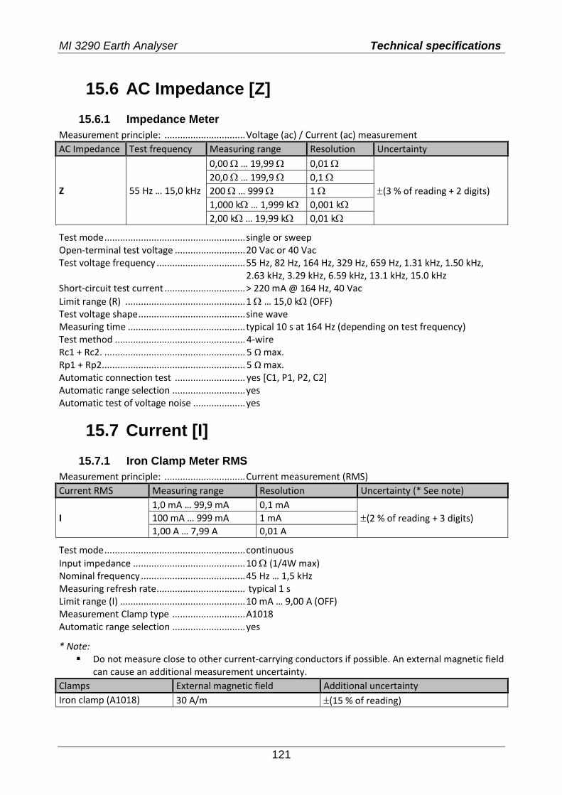
MI 3290 Earth Analyser Technical specifications
121
15.6 AC Impedance [Z]
15.6.1 Impedance Meter
Measurement principle: ............................... Voltage (ac) / Current (ac) measurement
AC Impedance Test frequency Measuring range Resolution Uncertainty
Z 55 Hz … 15,0 kHz
0,00 … 19,99 0,01
(3 % of reading + 2 digits)
20,0 … 199,9 0,1
200 … 999 1
1,000 k … 1,999 k 0,001 k
2,00 k … 19,99 k 0,01 k
Test mode ...................................................... single or sweep Open-terminal test voltage ........................... 20 Vac or 40 Vac Test voltage frequency .................................. 55 Hz, 82 Hz, 164 Hz, 329 Hz, 659 Hz, 1.31 kHz, 1.50 kHz, 2.63 kHz, 3.29 kHz, 6.59 kHz, 13.1 kHz, 15.0 kHz Short-circuit test current ............................... > 220 mA @ 164 Hz, 40 Vac
Limit range (R) .............................................. 1 … 15,0 k (OFF) Test voltage shape ......................................... sine wave Measuring time ............................................. typical 10 s at 164 Hz (depending on test frequency) Test method .................................................. 4-wire Rc1 + Rc2. ...................................................... 5 Ω max. Rp1 + Rp2 ....................................................... 5 Ω max. Automatic connection test ........................... yes [C1, P1, P2, C2] Automatic range selection ............................ yes Automatic test of voltage noise .................... yes
15.7 Current [I]
15.7.1 Iron Clamp Meter RMS
Measurement principle: ............................... Current measurement (RMS)
Current RMS Measuring range Resolution Uncertainty (* See note)
I
1,0 mA … 99,9 mA 0,1 mA
(2 % of reading + 3 digits) 100 mA … 999 mA 1 mA
1,00 A … 7,99 A 0,01 A
Test mode ...................................................... continuous
Input impedance ........................................... 10 (1/4W max) Nominal frequency ........................................ 45 Hz … 1,5 kHz Measuring refresh rate .................................. typical 1 s Limit range (I) ................................................ 10 mA … 9,00 A (OFF) Measurement Clamp type ............................ A1018 Automatic range selection ............................ yes
* Note: Do not measure close to other current-carrying conductors if possible. An external magnetic field
can cause an additional measurement uncertainty.
Clamps External magnetic field Additional uncertainty
Iron clamp (A1018) 30 A/m (15 % of reading)
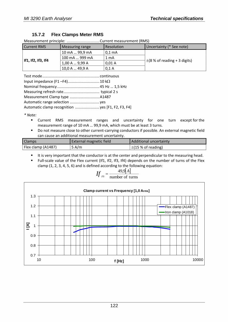
MI 3290 Earth Analyser Technical specifications
122
15.7.2 Flex Clamps Meter RMS
Measurement principle: ............................... Current measurement (RMS)
Current RMS Measuring range Resolution Uncertainty (* See note)
If1, If2, If3, If4
10 mA … 99,9 mA 0,1 mA
(8 % of reading + 3 digits) 100 mA … 999 mA 1 mA
1,00 A … 9,99 A 0,01 A
10,0 A … 49,9 A 0,1 A
Test mode ...................................................... continuous
Input impedance (F1 –F4).............................. 10 k Nominal frequency ........................................ 45 Hz … 1,5 kHz Measuring refresh rate .................................. typical 2 s Measurement Clamp type ............................ A1487 Automatic range selection ............................ yes Automatic clamp recognition ....................... yes [F1, F2, F3, F4]
* Note: Current RMS measurement ranges and uncertainty for one turn except for the
measurement range of 10 mA … 99,9 mA, which must be at least 3 turns. Do not measure close to other current-carrying conductors if possible. An external magnetic field
can cause an additional measurement uncertainty.
Clamps External magnetic field Additional uncertainty
Flex clamp (A1487) 5 A/m (15 % of reading)
It is very important that the conductor is at the center and perpendicular to the measuring head. Full-scale value of the Flex current (If1, If2, If3, If4) depends on the number of turns of the Flex
clamp (1, 2, 3, 4, 5, 6) and is defined according to the following equation:
turnsofnumber
9,49 AIf
FS
0.7
0.8
0.9
1
1.1
1.2
1.3
10 100 1000 10000
I [A
]
f [Hz]
Clamp current vs Frequency [1,0 Arms]
Flex clamp (A1487)
Iron clamp (A1018)

MI 3290 Earth Analyser Technical specifications
123
15.8 Influence of the auxiliary electrodes Definition of Rc, Rp and Ra: Rc ..................................................... Impedance of auxiliary current probes (Rh + Re) Rp ..................................................... Impedance of auxiliary potential probes (Rs + Res) Ra ..................................................... Earth resistance
Measurement function ........................................ 3, 4 – pole, Selective (Iron, Flex Clamp), Wenner and Schlumberger method, HF Earth Resistance (25 kHz)
Additional uncertainty if limit (Rh, Rs, Res, Re) or max. value are exceeded (whichever is lower).
Test frequency Limit for Rh and Rs Limit for Res and Re max. value
Additional uncertainty
55 Hz … 164 Hz > 100 Ω + (2 k * Ra) > 100 Ω + (1 k * Ra) 50 k (15 % of reading)
329 Hz … 659 Hz > 100 Ω + (1 k * Ra) > 100 Ω + (500 * Ra) 25 k (15 % of reading) 1,31 kHz … 2,63 kHz > 100 Ω + (500 * Ra) > 50 Ω + (250 * Ra) 12,5 k (15 % of reading) 3,29 kHz … 6,59 kHz > 100 Ω + (250 * Ra) > 50 Ω + (125 * Ra) 6,25 k (15 % of reading) 13,1 kHz … 15,0 kHz > 50 Ω + (150 * Ra) > 50 Ω + (50 * Ra) 3,1 k (15 % of reading) 25,0 kHz > 250 Ω + (500 * Ra) / 2 k (15 % of reading)
If the auxiliary probes limit is exceeded by an additional 50 % then the measuring range of the instrument is exceeded.
Standard uncertainty Additional error
≤ Limit ≤ Limit + 50%
or max. value
Impedance of auxiliary Rc and potential Rp probes
The measuring range of the instrument is exceeded. Measurement could not be started or displayed!
Notes: High impedance of auxiliary current or potential probes icon.
High impedance of auxiliary current and potential probes.
High impedance of auxiliary current probe Rc.
High impedance of auxiliary potential probe Rp.
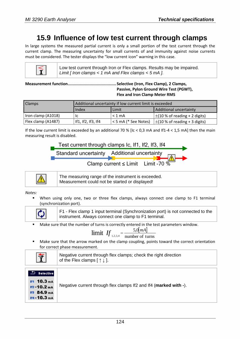
MI 3290 Earth Analyser Technical specifications
124
15.9 Influence of low test current through clamps In large systems the measured partial current is only a small portion of the test current through the current clamp. The measuring uncertainty for small currents of and immunity against noise currents must be considered. The tester displays the “low current icon” warning in this case.
Low test current through Iron or Flex clamps. Results may be impaired. Limit [ Iron clamps < 1 mA and Flex clamps < 5 mA ].
Measurement function ........................................ Selective (Iron, Flex Clamp), 2 Clamps, Passive, Pylon Ground Wire Test (PGWT), Flex and Iron Clamp Meter RMS
Clamps Additional uncertainty if low current limit is exceeded
Index Limit Additional uncertainty
Iron clamp (A1018) Ic < 1 mA (10 % of reading + 2 digits)
Flex clamp (A1487) If1, If2, If3, If4 < 5 mA (* See Notes) (10 % of reading + 3 digits)
If the low current limit is exceeded by an additional 70 % [Ic < 0,3 mA and If1-4 < 1,5 mA] then the main measuring result is disabled.
Standard uncertainty Additional uncertainty
Clamp current ≤ Limit Limit -70 %
Test current through clamps Ic, If1, If2, If3, If4
The measuring range of the instrument is exceeded. Measurement could not be started or displayed!
Notes: When using only one, two or three flex clamps, always connect one clamp to F1 terminal
(synchronization port).
F1 - Flex clamp 1 input terminal (Synchronization port) is not connected to the instrument. Always connect one clamp to F1 terminal.
Make sure that the number of turns is correctly entered in the test parameters window.
turnsofnumber
0,5limit
4,3,2,1
mAIf
Make sure that the arrow marked on the clamp coupling, points toward the correct orientation for correct phase measurement.
Negative current through flex clamps; check the right direction of the Flex clamps [ ↑ ↓ ].
Negative current through flex clamps If2 and If4 (marked with -).
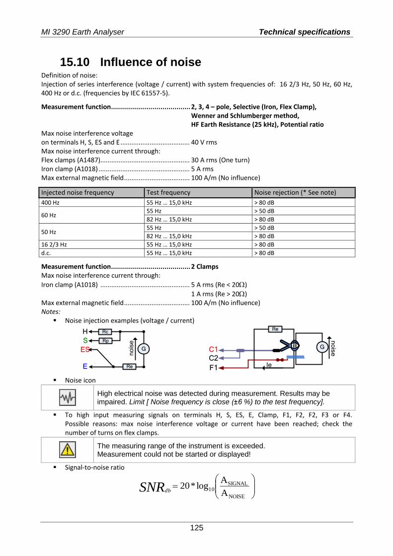
MI 3290 Earth Analyser Technical specifications
125
15.10 Influence of noise Definition of noise: Injection of series interference (voltage / current) with system frequencies of: 16 2/3 Hz, 50 Hz, 60 Hz, 400 Hz or d.c. (frequencies by IEC 61557-5).
Measurement function ........................................ 2, 3, 4 – pole, Selective (Iron, Flex Clamp), Wenner and Schlumberger method, HF Earth Resistance (25 kHz), Potential ratio Max noise interference voltage on terminals H, S, ES and E ...................................... 40 V rms Max noise interference current through: Flex clamps (A1487)................................................. 30 A rms (One turn) Iron clamp (A1018) .................................................. 5 A rms Max external magnetic field .................................... 100 A/m (No influence)
Injected noise frequency Test frequency Noise rejection (* See note)
400 Hz 55 Hz … 15,0 kHz > 80 dB
60 Hz 55 Hz > 50 dB
82 Hz … 15,0 kHz > 80 dB
50 Hz 55 Hz > 50 dB
82 Hz … 15,0 kHz > 80 dB
16 2/3 Hz 55 Hz … 15,0 kHz > 80 dB
d.c. 55 Hz … 15,0 kHz > 80 dB
Measurement function ........................................ 2 Clamps Max noise interference current through:
Iron clamp (A1018) ................................................. 5 A rms (Re < 20)
1 A rms (Re > 20) Max external magnetic field .................................... 100 A/m (No influence) Notes:
Noise injection examples (voltage / current)
Rp
RcH
S
E
GES
n
ois
e
Re
Ie
C1
C2
G
F1
Re
no
ise
Noise icon
High electrical noise was detected during measurement. Results may be impaired. Limit [ Noise frequency is close (±6 %) to the test frequency].
To high input measuring signals on terminals H, S, ES, E, Clamp, F1, F2, F2, F3 or F4. Possible reasons: max noise interference voltage or current have been reached; check the number of turns on flex clamps.
The measuring range of the instrument is exceeded. Measurement could not be started or displayed!
Signal-to-noise ratio
A
Alog*20
NOISE
SIGNAL10SNRdb
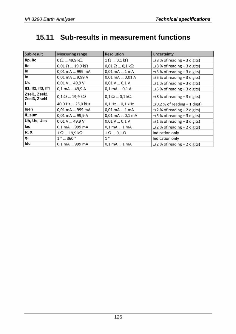
MI 3290 Earth Analyser Technical specifications
126
15.11 Sub-results in measurement functions
Sub-result Measuring range Resolution Uncertainty
Rp, Rc 0 … 49,9 k 1 … 0,1 k (8 % of reading + 3 digits)
Re 0,01 … 19,9 k 0,01 … 0,1 k (8 % of reading + 3 digits) Ie 0,01 mA … 999 mA 0,01 mA … 1 mA (3 % of reading + 3 digits) Ic 0,01 mA … 9,99 A 0,01 mA … 0,01 A (5 % of reading + 3 digits) Us 0,01 V … 49,9 V 0,01 V … 0,1 V (1 % of reading + 3 digits) If1, If2, If3, If4 0,1 mA … 49,9 A 0,1 mA … 0,1 A (5 % of reading + 3 digits) Zsel1, Zsel2, Zsel3, Zsel4 0,1 … 19,9 k 0,1 … 0,1 k (8 % of reading + 3 digits)
f 40,0 Hz … 25,0 kHz 0,1 Hz … 0,1 kHz (0,2 % of reading + 1 digit) Igen 0,01 mA … 999 mA 0,01 mA … 1 mA (2 % of reading + 2 digits) If_sum 0,01 mA … 99,9 A 0,01 mA … 0,1 mA (5 % of reading + 3 digits) Uh, Us, Ues 0,01 V … 49,9 V 0,01 V … 0,1 V (1 % of reading + 3 digits) Iac 0,1 mA … 999 mA 0,1 mA … 1 mA (2 % of reading + 2 digits) R, X 1 … 19,9 k 1 … 0,1 Indication only φ 1 ° … 360 ° 1 ° Indication only Idc 0,1 mA … 999 mA 0,1 mA … 1 mA (2 % of reading + 2 digits)
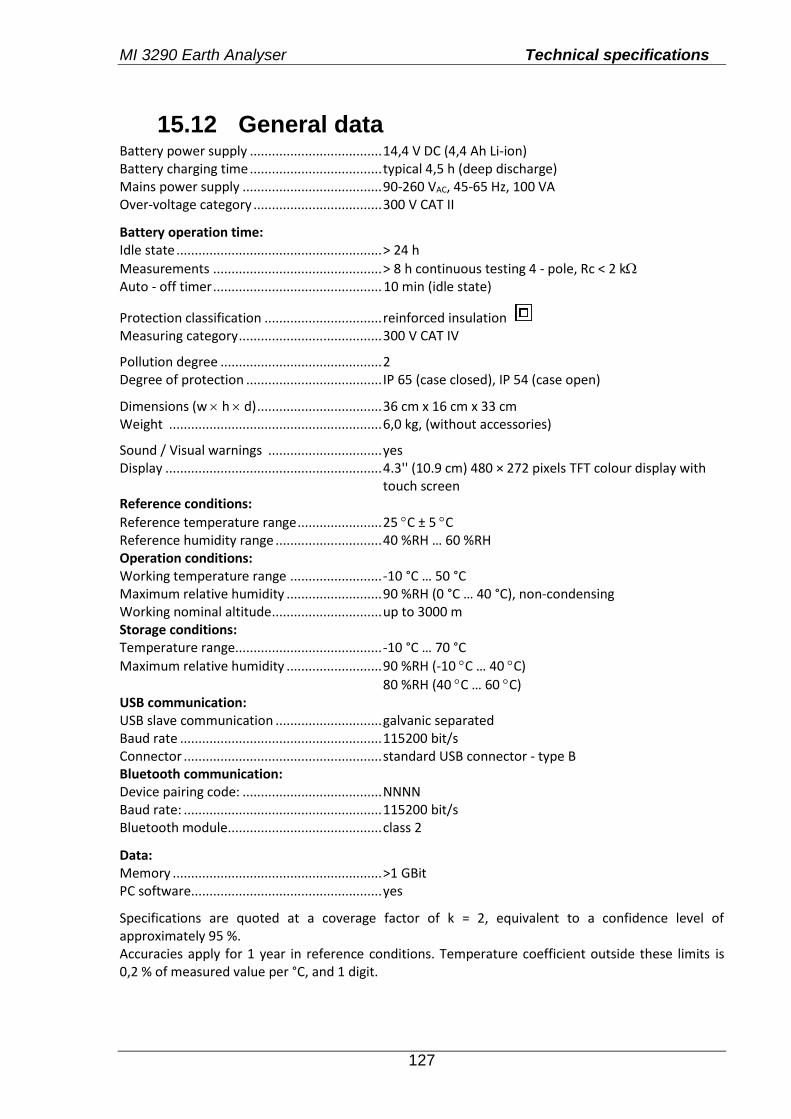
MI 3290 Earth Analyser Technical specifications
127
15.12 General data Battery power supply .................................... 14,4 V DC (4,4 Ah Li-ion) Battery charging time .................................... typical 4,5 h (deep discharge) Mains power supply ...................................... 90-260 VAC, 45-65 Hz, 100 VA Over-voltage category ................................... 300 V CAT II
Battery operation time: Idle state ........................................................ > 24 h
Measurements .............................................. > 8 h continuous testing 4 - pole, Rc < 2 k Auto - off timer .............................................. 10 min (idle state)
Protection classification ................................ reinforced insulation Measuring category ....................................... 300 V CAT IV
Pollution degree ............................................ 2 Degree of protection ..................................... IP 65 (case closed), IP 54 (case open)
Dimensions (w h d) .................................. 36 cm x 16 cm x 33 cm Weight .......................................................... 6,0 kg, (without accessories)
Sound / Visual warnings ............................... yes Display ........................................................... 4.3'' (10.9 cm) 480 × 272 pixels TFT colour display with touch screen Reference conditions:
Reference temperature range ....................... 25 C ± 5 C Reference humidity range ............................. 40 %RH … 60 %RH Operation conditions: Working temperature range ......................... -10 °C … 50 °C Maximum relative humidity .......................... 90 %RH (0 °C … 40 °C), non-condensing Working nominal altitude .............................. up to 3000 m Storage conditions: Temperature range........................................ -10 °C … 70 °C
Maximum relative humidity .......................... 90 %RH (-10 C … 40 C)
80 %RH (40 C … 60 C) USB communication: USB slave communication ............................. galvanic separated Baud rate ....................................................... 115200 bit/s Connector ...................................................... standard USB connector - type B Bluetooth communication: Device pairing code: ...................................... NNNN Baud rate: ...................................................... 115200 bit/s Bluetooth module .......................................... class 2
Data: Memory ......................................................... >1 GBit PC software.................................................... yes
Specifications are quoted at a coverage factor of k = 2, equivalent to a confidence level of approximately 95 %. Accuracies apply for 1 year in reference conditions. Temperature coefficient outside these limits is 0,2 % of measured value per °C, and 1 digit.
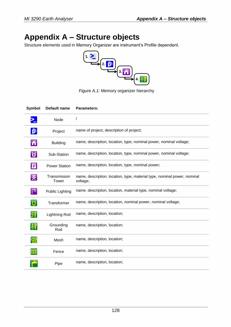
MI 3290 Earth Analyser Appendix A – Structure objects
128
Appendix A – Structure objects Structure elements used in Memory Organizer are instrument’s Profile dependent.
1.
2.
3.
4.
Figure A.1: Memory organizer hierarchy
Symbol Default name Parameters:
Node /
Project name of project, description of project;
Building name, description, location, type, nominal power, nominal voltage;
Sub-Station name, description, location, type, nominal power, nominal voltage;
Power Station name, description, location, type, nominal power;
Transmission
Tower name, description, location, type, material type, nominal power, nominal voltage;
Public Lighting name, description, location, material type, nominal voltage;
Transformer name, description, location, nominal power, nominal voltage;
Lightning Rod name, description, location;
Grounding
Rod name, description, location;
Mesh name, description, location;
Fence name, description, location;
Pipe name, description, location;
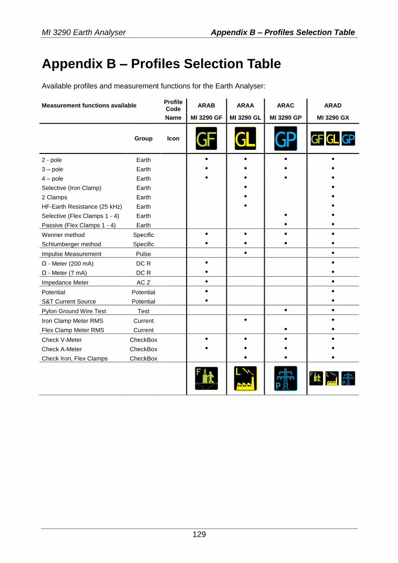
MI 3290 Earth Analyser Appendix B – Profiles Selection Table
129
Appendix B – Profiles Selection Table Available profiles and measurement functions for the Earth Analyser:
Measurement functions available Profile Code
ARAB ARAA ARAC ARAD
Name MI 3290 GF MI 3290 GL MI 3290 GP MI 3290 GX
Group Icon
2 - pole Earth • • • •
3 – pole Earth • • • •
4 – pole Earth • • • •
Selective (Iron Clamp) Earth • •
2 Clamps Earth • •
HF-Earth Resistance (25 kHz) Earth • •
Selective (Flex Clamps 1 - 4) Earth • •
Passive (Flex Clamps 1 - 4) Earth • •
Wenner method Specific • • • •
Schlumberger method Specific • • • •
Impulse Measurement Pulse • •
Ω - Meter (200 mA) DC R • •
Ω - Meter (7 mA) DC R • •
Impedance Meter AC Z • •
Potential Potential • •
S&T Current Source Potential • •
Pylon Ground Wire Test Test • •
Iron Clamp Meter RMS Current • •
Flex Clamp Meter RMS Current • •
Check V-Meter CheckBox • • • •
Check A-Meter CheckBox • • • •
Check Iron, Flex Clamps CheckBox • • •
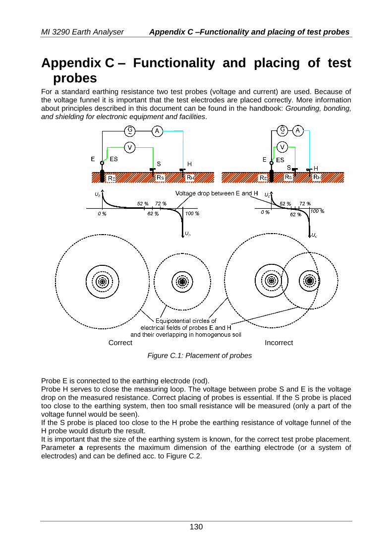
MI 3290 Earth Analyser Appendix C –Functionality and placing of test probes
130
Appendix C – Functionality and placing of test probes
For a standard earthing resistance two test probes (voltage and current) are used. Because of the voltage funnel it is important that the test electrodes are placed correctly. More information about principles described in this document can be found in the handbook: Grounding, bonding, and shielding for electronic equipment and facilities.
Correct Incorrect
Figure C.1: Placement of probes
Probe E is connected to the earthing electrode (rod). Probe H serves to close the measuring loop. The voltage between probe S and E is the voltage drop on the measured resistance. Correct placing of probes is essential. If the S probe is placed too close to the earthing system, then too small resistance will be measured (only a part of the voltage funnel would be seen). If the S probe is placed too close to the H probe the earthing resistance of voltage funnel of the H probe would disturb the result. It is important that the size of the earthing system is known, for the correct test probe placement. Parameter a represents the maximum dimension of the earthing electrode (or a system of electrodes) and can be defined acc. to Figure C.2.
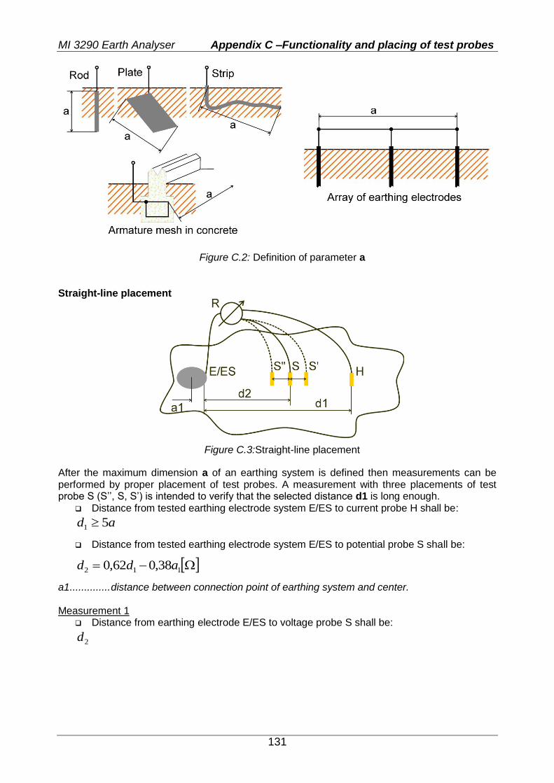
MI 3290 Earth Analyser Appendix C –Functionality and placing of test probes
131
Figure C.2: Definition of parameter a
Straight-line placement
Figure C.3:Straight-line placement
After the maximum dimension a of an earthing system is defined then measurements can be performed by proper placement of test probes. A measurement with three placements of test probe S (S’’, S, S’) is intended to verify that the selected distance d1 is long enough.
Distance from tested earthing electrode system E/ES to current probe H shall be:
ad 51
Distance from tested earthing electrode system E/ES to potential probe S shall be:
112 38,062,0 add
a1 .............. distance between connection point of earthing system and center. Measurement 1
Distance from earthing electrode E/ES to voltage probe S shall be:
2d
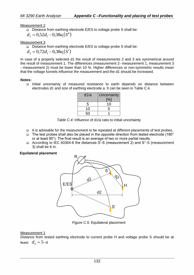
MI 3290 Earth Analyser Appendix C –Functionality and placing of test probes
132
Measurement 2 Distance from earthing electrode E/ES to voltage probe S shall be:
Sadd 112 38,052,0
Measurement 3 Distance from earthing electrode E/ES to voltage probe S shall be:
Sadd 112 38,072,0
In case of a properly selected d1 the result of measurements 2 and 3 are symmetrical around the result of measurement 1. The differences (measurement 2- measurement 1, measurement 3 - measurement 2) must be lower than 10 %. Higher differences or non-symmetric results mean that the voltage funnels influence the measurement and the d1 should be increased. Notes:
Initial uncertainty of measured resistance to earth depends on distance between electrodes d1 and size of earthing electrode a. It can be seen in Table C.4.
d1/a Uncertainty [%]
5 10
10 5
50 1
Table C.4: Influence of d1/a ratio to initial uncertainty
It is advisable for the measurement to be repeated at different placements of test probes. The test probes shall also be placed in the opposite direction from tested electrode (180°
or at least 90°). The final result is an average of two or more partial results. According to IEC 60364-6 the distances S’-S (measurement 2) and S’’-S (measurement
3) shall be 6 m.
Equilateral placement
Figure C.5: Equilateral placement
Measurement 1 Distance from tested earthing electrode to current probe H and voltage probe S should be at
least: ad 52
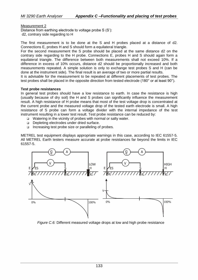
MI 3290 Earth Analyser Appendix C –Functionality and placing of test probes
133
Measurement 2 Distance from earthing electrode to voltage probe S (S’): d2, contrary side regarding to H The first measurement is to be done at the S and H probes placed at a distance of d2. Connections E, probes H and S should form a equilateral triangle. For the second measurement the S probe should be placed at the same distance d2 on the contrary side regarding to the H probe. Connections E, probes H and S should again form a equilateral triangle. The difference between both measurements shall not exceed 10%. If a difference in excess of 10% occurs, distance d2 should be proportionally increased and both measurements repeated. A simple solution is only to exchange test probes S and H (can be done at the instrument side). The final result is an average of two or more partial results. It is advisable for the measurement to be repeated at different placements of test probes. The test probes shall be placed in the opposite direction from tested electrode (180° or at least 90°). Test probe resistances In general test probes should have a low resistance to earth. In case the resistance is high (usually because of dry soil) the H and S probes can significantly influence the measurement result. A high resistance of H probe means that most of the test voltage drop is concentrated at the current probe and the measured voltage drop of the tested earth electrode is small. A high resistance of S probe can form a voltage divider with the internal impedance of the test instrument resulting in a lower test result. Test probe resistance can be reduced by:
Watering in the vicinity of probes with normal or salty water. Depleting electrodes under dried surface. Increasing test probe size or paralleling of probes.
METREL test equipment displays appropriate warnings in this case, according to IEC 61557-5. All METREL Earth testers measure accurate at probe resistances far beyond the limits in IEC 61557-5.
Figure C.6: Different measured voltage drops at low and high probe resistance
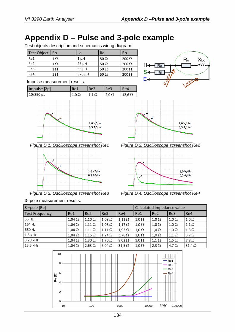
MI 3290 Earth Analyser Appendix D –Pulse and 3-pole example
134
Appendix D – Pulse and 3-pole example Test objects description and schematics wiring diagram:
Test Object Ro Lo Rc Rp
Re1 1 1 µH 50 200
Re2 1 25 µH 50 200
Re3 1 55 µH 50 200
Re4 1 376 µH 50 200
Impulse measurement results:
Impulse [Zp] Re1 Re2 Re3 Re4
10/350 µs 1,0 1,1 2,0 12,6
Ro
Rp
RcH
S
Ei p
robe
u p
robe
XLo
Figure D.1: Oscilloscope screenshot Re1 Figure D.2: Oscilloscope screenshot Re2
Figure D.3: Oscilloscope screenshot Re3 Figure D.4: Oscilloscope screenshot Re4
3- pole measurement results:
3 –pole [Re] Calculated impedance value
Test Frequency Re1 Re2 Re3 Re4 Re1 Re2 Re3 Re4
55 Hz 1,04 1,10 1,08 1,11 1,0 1,0 1,0 1,0
164 Hz 1,04 1,11 1,08 1,17 1,0 1,0 1,0 1,1
660 Hz 1,04 1,11 1,11 1,93 1,0 1,0 1,0 1,8
1,5 kHz 1,04 1,15 1,24 3,78 1,0 1,0 1,1 3,7
3,29 kHz 1,04 1,30 1,70 8,02 1,0 1,1 1,5 7,8
13,3 kHz 1,04 2,63 5,04 31,5 1,0 2,3 4,7 31,4
0
2
4
6
8
10
10 100 1000 10000 100000f [Hz]
Re
[Ω
]
Re1
Re2
Re3
Re4
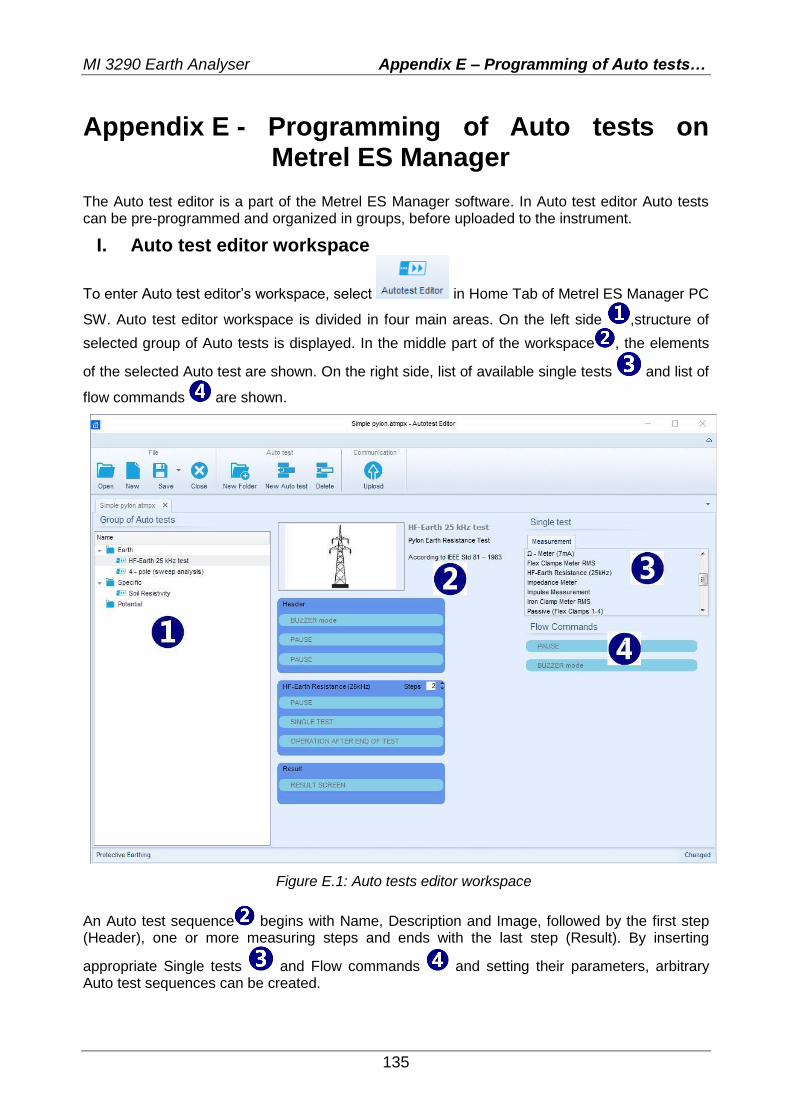
MI 3290 Earth Analyser Appendix E – Programming of Auto tests…
135
Appendix E - Programming of Auto tests on Metrel ES Manager
The Auto test editor is a part of the Metrel ES Manager software. In Auto test editor Auto tests can be pre-programmed and organized in groups, before uploaded to the instrument.
I. Auto test editor workspace
To enter Auto test editor’s workspace, select in Home Tab of Metrel ES Manager PC
SW. Auto test editor workspace is divided in four main areas. On the left side ,structure of
selected group of Auto tests is displayed. In the middle part of the workspace , the elements
of the selected Auto test are shown. On the right side, list of available single tests and list of
flow commands are shown.
Figure E.1: Auto tests editor workspace
An Auto test sequence begins with Name, Description and Image, followed by the first step (Header), one or more measuring steps and ends with the last step (Result). By inserting
appropriate Single tests and Flow commands and setting their parameters, arbitrary Auto test sequences can be created.
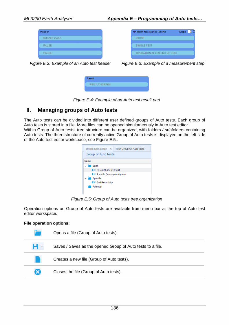
MI 3290 Earth Analyser Appendix E – Programming of Auto tests…
136
Figure E.2: Example of an Auto test header Figure E.3: Example of a measurement step
Figure E.4: Example of an Auto test result part
II. Managing groups of Auto tests
The Auto tests can be divided into different user defined groups of Auto tests. Each group of Auto tests is stored in a file. More files can be opened simultaneously in Auto test editor. Within Group of Auto tests, tree structure can be organized, with folders / subfolders containing Auto tests. The three structure of currently active Group of Auto tests is displayed on the left side of the Auto test editor workspace, see Figure E.5..
Figure E.5: Group of Auto tests tree organization
Operation options on Group of Auto tests are available from menu bar at the top of Auto test editor workspace. File operation options:
Opens a file (Group of Auto tests).
Saves / Saves as the opened Group of Auto tests to a file.
Creates a new file (Group of Auto tests).
Closes the file (Group of Auto tests).
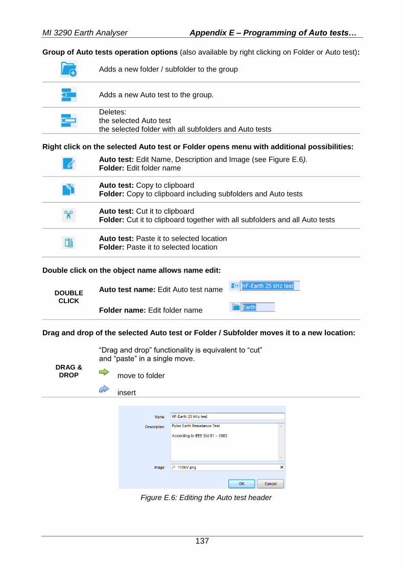
MI 3290 Earth Analyser Appendix E – Programming of Auto tests…
137
Group of Auto tests operation options (also available by right clicking on Folder or Auto test):
Adds a new folder / subfolder to the group
Adds a new Auto test to the group.
Deletes: the selected Auto test the selected folder with all subfolders and Auto tests
Right click on the selected Auto test or Folder opens menu with additional possibilities:
Auto test: Edit Name, Description and Image (see Figure E.6). Folder: Edit folder name
Auto test: Copy to clipboard Folder: Copy to clipboard including subfolders and Auto tests
Auto test: Cut it to clipboard Folder: Cut it to clipboard together with all subfolders and all Auto tests
Auto test: Paste it to selected location Folder: Paste it to selected location
Double click on the object name allows name edit:
DOUBLE CLICK
Auto test name: Edit Auto test name
Folder name: Edit folder name
Drag and drop of the selected Auto test or Folder / Subfolder moves it to a new location:
DRAG & DROP
“Drag and drop” functionality is equivalent to “cut” and “paste” in a single move.
move to folder
insert
Figure E.6: Editing the Auto test header
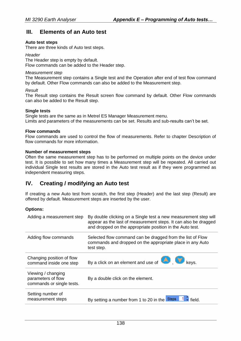
MI 3290 Earth Analyser Appendix E – Programming of Auto tests…
138
III. Elements of an Auto test
Auto test steps There are three kinds of Auto test steps.
Header The Header step is empty by default. Flow commands can be added to the Header step.
Measurement step The Measurement step contains a Single test and the Operation after end of test flow command by default. Other Flow commands can also be added to the Measurement step.
Result The Result step contains the Result screen flow command by default. Other Flow commands can also be added to the Result step. Single tests Single tests are the same as in Metrel ES Manager Measurement menu. Limits and parameters of the measurements can be set. Results and sub-results can’t be set. Flow commands Flow commands are used to control the flow of measurements. Refer to chapter Description of flow commands for more information. Number of measurement steps Often the same measurement step has to be performed on multiple points on the device under test. It is possible to set how many times a Measurement step will be repeated. All carried out individual Single test results are stored in the Auto test result as if they were programmed as independent measuring steps.
IV. Creating / modifying an Auto test
If creating a new Auto test from scratch, the first step (Header) and the last step (Result) are offered by default. Measurement steps are inserted by the user. Options:
Adding a measurement step By double clicking on a Single test a new measurement step will appear as the last of measurement steps. It can also be dragged and dropped on the appropriate position in the Auto test.
Adding flow commands Selected flow command can be dragged from the list of Flow commands and dropped on the appropriate place in any Auto test step.
Changing position of flow command inside one step By a click on an element and use of , keys.
Viewing / changing parameters of flow commands or single tests.
By a double click on the element.
Setting number of measurement steps
By setting a number from 1 to 20 in the field.
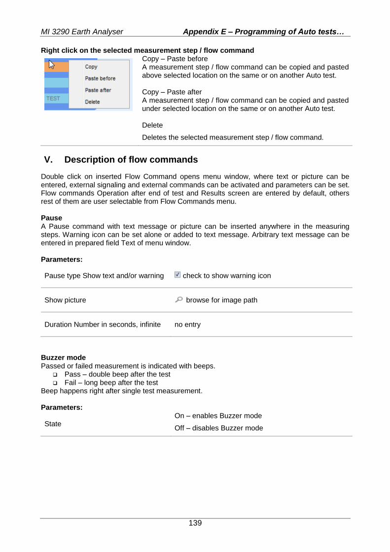
MI 3290 Earth Analyser Appendix E – Programming of Auto tests…
139
Right click on the selected measurement step / flow command
Copy – Paste before A measurement step / flow command can be copied and pasted above selected location on the same or on another Auto test. Copy – Paste after A measurement step / flow command can be copied and pasted under selected location on the same or on another Auto test. Delete
Deletes the selected measurement step / flow command.
V. Description of flow commands
Double click on inserted Flow Command opens menu window, where text or picture can be entered, external signaling and external commands can be activated and parameters can be set. Flow commands Operation after end of test and Results screen are entered by default, others rest of them are user selectable from Flow Commands menu. Pause A Pause command with text message or picture can be inserted anywhere in the measuring steps. Warning icon can be set alone or added to text message. Arbitrary text message can be entered in prepared field Text of menu window. Parameters:
Pause type Show text and/or warning check to show warning icon
Show picture browse for image path
Duration Number in seconds, infinite no entry
Buzzer mode Passed or failed measurement is indicated with beeps.
Pass – double beep after the test Fail – long beep after the test
Beep happens right after single test measurement. Parameters:
State On – enables Buzzer mode
Off – disables Buzzer mode
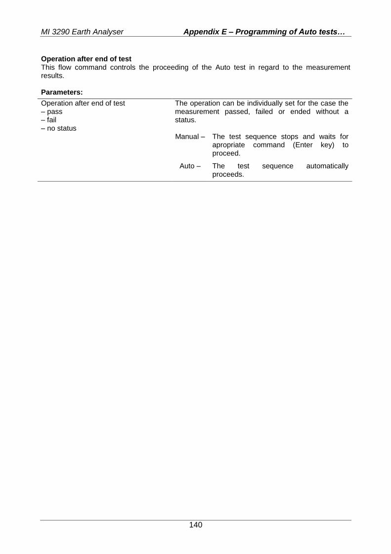
MI 3290 Earth Analyser Appendix E – Programming of Auto tests…
140
Operation after end of test This flow command controls the proceeding of the Auto test in regard to the measurement results. Parameters:
Operation after end of test – pass – fail – no status
The operation can be individually set for the case the measurement passed, failed or ended without a status.
Manual – The test sequence stops and waits for
apropriate command (Enter key) to proceed.
Auto – The test sequence automatically proceeds.