metrel general catalog engl 2015
TRANSCRIPT

7/25/2019 METREL General Catalog Engl 2015
http://slidepdf.com/reader/full/metrel-general-catalog-engl-2015 1/121
www.metrel.si
Catalogue2015
Measuringinstrumentsand testers

7/25/2019 METREL General Catalog Engl 2015
http://slidepdf.com/reader/full/metrel-general-catalog-engl-2015 2/121
32
Measuring and Regulation EquipmentMETREL d.d.Ljubljanska c. 77SI-1354 HorjulTel: +386 (0)1 7558 200E-mail: metrel∞metrel.si
www.metrel.si
Mess und PrüftechnikMetrel GmbHOrchideenstraße 2490542 EckentalTel.: +49 (0) 9126 28996-0E-mail: metrel∞metrel.de
www.metrel.de
Test and Measuring Equipment Metrel UKUnit 1, Hopton House, Ripley Drive,Normanton, West Yorkshire, WF6 1QTTel.: +44 (0) 1924 245 000E-mail: info∞metrel.co.uk
www.metrel.co.uk
Measuring and Regulation Equipment Manufacturer
GERMAN market
UK market
GLOBAL market
Metrel - Measuring and Regulation Equipment Manufacturer
Metrel is an international Group and anexpert in the research, developmentand production of test and measure-ment equipment. Metrel brand name isworldwide recognized and associatedwith high quality test and measurementproducts.
Metrel’s instruments provide test andmeasurement solutions in differentmaintenance areas including the safetytesting of electrical installations and ap-pliances, power quality analysis, localarea network analysis and the meas-urement of indoor environmental con-ditions. In short, our products help toprovide information about the safety andfunctionality of different installations andenvironments. Through innovative de-sign, electronics and software solutionswe provide accurate, reliable and safe touse products.
The company strives to be the leaderin advanced technological solutions andtherefore invests over 10 % of the yearlyturnover into the R&D department.
Our wide range of products is backed upwith a complete support package includ-ing repair and calibration, technical sup-port and customer training programs. Adetailed calibration certificate is suppliedas standard with all Metrel products.
SALES NETWORK
Metrel’s products are sold and servicedin over 80 countries by local agents anddistributors. Our associated companiesare managed by local people who knowthe special needs of their markets. Salesengineers and specially trained techni-cians staff give excellent service to ourcustomers.
The GERMAN market is supported byMetrel GmbH based in Eckental (www.metrel.de) and the UK market is support-ed by Metrel UK based in Normanton(www.metrel.co.uk ). Inquiries for othercountries please direct to Metrel d.d.,the headquarters based in SLOVENIA(www.metrel.si ).
COMMITMENT TO QUALITY
Metrel’s quality assurance system isbased on BS EN ISO 9001. Throughpermanent training and education of ouremployees we strive to increase the ef-ficiency and quality of all our processes.
Our commitment to quality is recognizedby our customers and is ensured by con-tinuous and extensive research and de-velopment of new, accurate, reliable andsafe to use products.
ECOLOGY
Metrel test and measurement equip-ment complies to the RoHS and WEEEdirectives. Metrel strives to meet itsgoals with the most efficient use of re-sources and the least possible impact onthe environment.
RESEARCH, DEVELOPMENT ANDPRODUCTION
The research, development and pro-duction of Metrel’s products are basedin Europe (Slovenia) at Metrel d.d. Thecompany strives for total quality control.A dedicated quality assurance depart-ment ensures strict adherence to cus-tomer specifications. Highly competentR&D engineers provide advanced solu-tions for our customers.
TEST LABORATORY
The highly professional test laboratorybased in Metrel d.d. provides internal
services including the testing of compo-nents, subassemblies and prototypes ofproducts. This enables Metrel to launchsafe and reliable new products into themarket. The laboratory provides testingaccording to the Low Voltage Directive(2006/95/EC) and the EMC Directive(2004/108/EC). The main standards thatMetrel also complies to include IEC/EN61010 and IEC/EN 61326.
PRODUCTS
Metrel is producing test and measure-ment equipment that is covering the fol-lowing fields:• Electrical Installations Safety Testing
(IEC/EN 61557, VDE 0413, VDE 0100,BS 7671, HD 60364, CEI 64.8, AS/NZS3017, AS/NZS3760).
• Portable Appliances, Machines andSwitchgears Safety Testing (IEC/EN60204-1, IEC/EN 61439-1, IEC/EN60335-1, VDE 0701-0702).
• Measurement and Testing of CableNetworks (TIA/EIA-568-B, ISO 11801,EN 50173, EN 50346, IEC/EN 61935).
• Testing of Power Distribution Sys-tems and Power Quality Analysis (EN 50160).
• Analysis of Indoor EnvironmentQuality (DIN 5032, IEC/EN 60584-1,EN 12599, EN ISO 7726, ISO 11664).
• Equipment f or Laborator ies andSchools: Metrel produces a varietyof instruments for electrical testinglaboratories and educational purposes.Typical application areas are: electri-cal workshops, testing labs, research,development and education. The main
products Metrel produces includedemo boards, power supply units, R-L-C decades.
• Transformers: Metrel produces twokinds of toroidal transformers: variabletransformers (according to standardEN60989) and power transformers(according to standard EN 61558).
Besides the test and measurementproduct portfolio offered by Metrel d.d.Metrel’s daughter company Metrel Me-hanika d.o.o. also provide a variety ofproducts focusing on metal process-ing. Their core business is sheet metalproduction, milled / turned production,manufacturing of tools and surface pro-tection. For more information pleasevisit www.metrel-mehanika.si.

7/25/2019 METREL General Catalog Engl 2015
http://slidepdf.com/reader/full/metrel-general-catalog-engl-2015 3/121

7/25/2019 METREL General Catalog Engl 2015
http://slidepdf.com/reader/full/metrel-general-catalog-engl-2015 4/121
6
Contents
Electrical Installation Safety
1.1 - 1.68
High Voltage Diagnostics
2.1 - 2.36
Appliance / Machine /Switchboard Safety
3.1 - 3.40
Power Quality Analysis
4.1 - 4.26
LAN Cabling Certification
5.1 - 5.08
Indoor Environment Quality
6.1 - 6.16
Digital Multimeters / ClampMeters / Voltage andContinuity Testers
7.1 - 7.32
Variable transformers /Equipment for laboratoriesand Schools
8.1 - 8.05
GOOD TO KNOWTesting the Safety of Electrical Installation 1 - 02
PHOTOVOLTAIC AND ELECTRICAL INSTALLATIONS TESTERSelection Guide for Photovoltaic and Electrical installations Testers 1 - 07
MI 3108 EurotestPV 1 - 08MI 3109 EurotestPV Lite 1 - 10
MULTIFUNCTIONAL TESTERSSelection Guide for Multifunctional Testers 1 - 12
MI 3152 EurotestXC NEW 1 - 14MI 3105 EurotestXA 1 - 16MI 3101 EurotestAT 1 - 18MI 3102H BT EurotestXE 2,5 kV 1 - 20MI 3102 BT EurotestXE 1 - 22MI 3100 SE EurotestEASI 1 - 24MI 3100 s EurotestEASI 1 - 26MI 3125BT EurotestCOMBO 1 - 28MI 3125 EurotestCOMBO 1 - 30MI 2086 Eurotest 61557 1 - 32MI 2088 Earth - Insulation Tester 1 - 34
SINGLE-FUNCTIONAL TESTERSSelection Guide for Single-functional Testers 1 - 36
MI 3121 Insulation / Continuity 1 - 38MI 3122 Z Line-Loop / RCD 1 - 40MI 3123 Earth / Clamp 1 - 42MI 3110 EurotestIM 1 - 44MI 2126 Earth 2/3 1 - 46MI 3103 GigaOhm 1 kV 1 - 47
OTHER INSTRUMENTS / ADAPTERS / ACCESSORIESA 1143 Euro Z 290 A 1 - 48
MI 2093 Line Tracer 1 - 49A 1199 ρ adapter 1 - 50CS 2099 Eurocheck 1 - 51DEMONSTRATION BOARDS
MI 3088 PV Demonstration Board 1 - 52MA 2067 Demonstration Board 1 - 53MI 3099 Demonstration Board 1 - 54MI 2166 Demonstration Board 1 - 55
PC SOFTWAREMetrel Electrical Safety Manager NEW 1 - 56EuroLink PRO and EuroLink PRO Plus 1 - 57A 1431 EuroLink Android 1 - 58A 1428 EuroLinkPV Android 1 - 59
Selection Guide for EIS Accessories 1 - 60
E l e c t r i c
a l I n s t a l l a t i o n S a f e t y
C o m p l i a n t w i t h I E C / E N 6 1
5 5 7 E l e c t r i c a l I n s t a l l a t i o n S a f e t y S t a n d a r dMEASURING INSTRUMENTS AND TESTERS
CATALOGUE 2015
Electrical Installation Safety

7/25/2019 METREL General Catalog Engl 2015
http://slidepdf.com/reader/full/metrel-general-catalog-engl-2015 5/121
Electrical Installation Safety Electrical Installation Safety
1. 2 1. 3Accessories: page 1.60 Accessories: page 1.60
Find out more about testing safety ofelectrical installationsAccording to European standards require-ments electrical installation safety testingincludes a combination of following tests:• Insulation resistance,• Continuity of protective conductors
and equipotential bonding,• RCD testing,• Line and fault loop impedance,• Earth resistance testing (two-wire
method without probes, three / four-wire method with two probes, methodwith current clamp and two probes,method with two current clamps)
• Specific earth resistance,• Phase sequence, voltage and frequency.
These tests are performed in order to en-sure that the requirements are met for the
protection of persons, livestock and prop-erty against the risk of electric shock andto ensure that the automatic disconnec-
tion of the supply is performed correctly.
Insulation resistanceThe insulation is intended to prevent any
contact with live parts and withstanding
mechanical, chemical, electrical and ther-
mal stresses. Insulation test discloses in-
sulation faults caused by pollution, mois-
ture, deterioration of insulation materials
etc. Insulation resistance measurement is
covered by the IEC / EN 61557-2 standard.
The power must be switched off and theinstallation must be disconnected beforeperforming this test to ensure that thetest voltage will not be applied to otherequipment electrically connected to thecircuit to be tested, particularly devicessensitive to voltage surges.
Insulation resistance shall be measuredbetween:• Line conductors,• Line and PE conductors,• Line and Neutral conductors,• Neutral and PE conductors.
Test circuit for insulation resistance measurement
Test circuit for insulation resistance measurement
The insulation resistance test is per-formed with a DC voltage on a dead sys-tem and the resistance must be above
the minimum limit set out in the appro-priate standards and regulations.Limit values for electrical installationsacc. to IEC 60364-6:
Ratedt voltage ofcircuit (V)
DC testvoltage (V)
Insulationresistance (MΩ)
LV secondary switch-board or LV mainswitshboard
250 ≥0.5
Less than or equal to500 V including LV mainswitchboard
500 ≥1.0
Greater 1.000 ≥1.0
METREL’s hint:EurotestAT and EurotestXA have built-in the“Insulation ALL” function which enables
performing of 3-port insulation test (L-N,L-PE, N-PE or L1-L2, L1-L3, L2-L3) in onestep. This is a very time saving feature es-pecially if measuring insulation on outlets.
Continuity of protective conductorsand equipotential bondingThe purpose of continuity measurementis to check the continuity of the protec-tive conductors, the main and supple-mentary equipotential bonds.The test is carried out using a measure-ment instrument capable of generatinga no-load voltage of 4 to 24 V (DC or AC)with a minimal current of 200 mA.
Continuity test is covered by the EN61557-4 standard.
The measured resistance must be lowerthan a threshold specified by the stand-ard applicable to the installation tested,which is usually 2 Ω. As the resistancevalue is low, the resistance of the meas-urement leads must be compensated,particularly if very long leads are used.
METREL’s hint:EurotestAT and EurotestXA can perform theN – PE loop test between instrument’s Nand PE test terminals. This makes testingwith the plug test cable on outlets possible.
Test circuit for continuity R200 mA measurement
Test circuit for continuous resistance measurement
RCD testingRCD devices are used as protection
against dangerous fault voltages and faultcurrents. Various test and measurementsare required for verification of RCDs inRCD protected installations. Measure-ments are based on the EN 61557-6standard.Scope of RCD test is:• to verify effectiveness and proper op-
eration of the RCDs;• to verify disconnection times and trip
out currents of RCDs;• to verify that there are no or limited pre-
sent fault currents in the installation.
The following measurements and testsof RCDs can be performed:• Contact voltage,• Trip-out time,• Trip-out current,• RCD autotest.
Circuit for testing RCD
METREL’s hint:
METREL installation testers have built-inthe “RCD AUTO” function which performs
RCD testing at x1/2, x1 and x5 current mul-tipliers at both 0° and 180° automatically.
With this function all relevant RCD testscan be carried out in one step which is verysimple and time saving feature.
RCD selection table according to theirsensitivity:
AC type
A type
B type
t
U
t
U
No
response
t
UNo
responseNo
response
Line impedanceLine impedance is measured in loopcomprising of mains voltage sourceand line wiring (between the line andneutral conductors or between lines ona 3-phase system). It is covered by re-quirements of the EN 61557-3 standard.
Scope of line impedance test is:• to verify effectiveness of installed over
current devices;• to verify internal impedance for supply-
ing purpose.
The line-neutral short circuit loop consists of:• Power transformer secondary imped-
ance ZT,• ZL (phase wiring from source to fault),• ZN (neutral wiring from source to fault).The line to neutral impedance is thesum of impedances and resistances thatforms the line to neutral loop. In threephase system there are three line-neu-
tral impedances (ZL1-N, ZL2-N, ZL3-N).
ZLN = ZL+ ZN+ZTLN
The prospective short circuit current IPSC is defined as:
Circuit for measurement of line impedance
IPSC must be higher than current for rateddisconnection time of the over currentdisconnection device. The line – neutral(or line - line) impedance should be lowenough e.g. prospective short circuit cur-rent high enough that installed protectiondevice will disconnect the short circuitloop within the prescribed time interval.
METREL’s hint:
METREL installation testers have built-intables with fuses and RCDs parameters.When line test is performed, the meas-ured value is automatically comparedto the maximum values set out in thestandard (EN 61557) and either a PASSor FAIL symbol will appear on the screento inform the user if the result is withinthe required limits.
Fault loop impedanceFault loop is a loop comprising mains
source, line wiring and PE return path to the
mains source. The measurement is cov-
ered by requirements of the EN 61557-3
standard.
Scope of loop impedance test is:• to verify effectiveness of installed over
current and / or residual current discon-nection devices;
• to verify fault loop impedances, prospec-
tive fault currents and fault voltage values.
In TN systems the fault loop ZL-PE consists of:
• ZT (power transformer secondary impedance);
• ZL (phase wiring from source to fault);• RPE (PE / PEN wiring from fault to source).
The fault loop impedance is the sum of
impedances and resistances that formsthe fault loop.
ZLPE = ZL+ RPE+ZT
The prospective fault current IPSC is defined as:
Circuit for measurement of fault loop impedance
>Ia____ULPE
ZLPEIPSC=____ULN
ZLNIPSC= >Ia
Electrical Installation Safety Testing Electrical Installation Safety Testing
METREL’s hint:
METREL installation testers have built-intables with fuses and RCDs parameters.When loop test is performed, the meas-ured value is automatically comparedto the maximum values set out in thestandard (EN 61557) and either a PASSor FAIL symbol will appear on the screento inform the user if the result is withinthe required limits.
Earth resistanceEarth resistance testing is used on TN, TTand IT systems to ensure that the resist-ance of the earth electrode is sufficientlylow so that, in the case of a fault, a dan-gerous voltage does not appear on anyparts of the installation or on any appli-ances which have a connection to earth.
The measurement conforms to the EN61557-6 standard.
Scope of earth resistance test is:• Earthing of exposed conductive parts
assures that the voltage on them staysbelow dangerous level in case of a fault.
In TN installations the earthing is realizedat the source and / or distribution pointsthat’s why the earthing resistances areusually very low (below 1Ω).
TT installations have their own mainearthing. The resistances are usuallyhigher than in TN systems (from few Ω up to several hundred Ω). Because ofthis dangerous fault voltages and bodycurrents can occur at relatively low faultcurrents. Therefore TT systems usually
have additional RCD protection.
The following earth resistance measur-ing methods are available:• Standard 3-wire (4-wire) method for
standard resistance to earth measure-
ments;
• 3-wire (4-wire) method with oneclamp, for measuring resistance toearth of individual earthing rods;
• Two clamps method for measuring re-sistance to earth of individual earthingrods (recommended in IEC 60364-6 forurban areas);
• Specific earth resistance (is carried outin order to assure more accurate calcu-lation of earthing systems e.g. for high-voltage distribution columns, large in-dustrial plants, lightning systems etc.).
GOOD TO KNOW GOOD TO KNOW

7/25/2019 METREL General Catalog Engl 2015
http://slidepdf.com/reader/full/metrel-general-catalog-engl-2015 6/121
Electrical Installation Safety Electrical Installation Safety
1. 4 1. 5Accessories: page 1.60 Accessories: page 1.60
Connection diagrams:
Circuits for three-wire mesurement
Circuits for three-wire mesurement
Circuit for two clamps measurement
Circuit for one clamp measurement
Circuit for measurement of spesific earth resistance
Recommended earth resistance meas-uring methods:TN system
1
L2
L3
PETN
N
Two clamps method (clamps around main N/PE cable).
TT system
L1
L2
L3
PE
N
TT
Two-wire method (test from the socket between N and PE)
IT system L1
L2
L3
PE
N
TT
Three-wire method (test leads to auxiliary rods in triangle)
Lightning conductor
Two clamps method
Limits: 2 Ω – above ground,10 Ω – complete system,20 Ω – individual electrode or 8% of spe-cific earth resistance.
Phase sequence, voltage and frequencyPhase sequence test is used for deter-mining of line voltages order in 3-phasesystems. This order defines direction ofrotation of motors and generators.
Phase sequence measurement con-forms to the EN 61557-7 standard.
Circuit for voltage measurements
Circuit for voltage measurement, frequency and phase se-
quence
METREL’s hint:
METREL installation testers have on-line voltage monitor which in all func-tions displays on one screen voltagesbetween L to PE, L to N and N to PE(single phase system) or L1 to L2, L2 toL3 and L1 to L3 (3-phase system). Thisfeature allows quickly identify incorrectconnections, disconnected wires or in-correct voltages.
PE test terminalA very dangerous situation can occur incase dangerous voltage is applied to thePE wire or other accessible metal parts.A common reason for this fault is incor-rect wiring. Metrel’s instruments areequipped with touchable PE electrode(TEST key). When touching TEST key inall functions that require mains supplythe user automatically performs test forthe presence of phase voltage at the PEprotection terminal.
Example for application of PE test terminal
Electrical Installation Safety Testing
Overvoltage categoryThe overvoltage category specifiesthe highest mains voltage (or lightningstrike, short circuit due to incorrect use,etc.) that the instrument can withstandwithout danger for the tester or for theobject being measured. The standardspecifies four overvoltage categories.The overvoltage category affects com-ponent sizing via the air gap. The higherthe category, the bigger is the distanceto the power source.
CAT I - electronic devices, signal level.CAT II - domestic appliances, portableappliances, single-phase loads, sockets,(>10 m from CAT III; >20 m from CAT IV).CAT III - three-phase distribution sys-tems, lighting systems in large buildings,distribution panels.CAT IV - three-phase systems on power
stations, electricity meters, outdoor instal-
lations and supply cable incoming feed.
CAT IICAT I CAT IVCAT III
AUTO SEQUENCE® is a unique patented by Metrel testing pro-cedure which allows performing of seriesof requested installation tests with a sin-gle press of TEST button. The results of
each test are automatically compared topre-set limits and PASS / FAIL evaluated.
While ensuring efficient, fast and easyway of installation safety testing AUTOSEQUENCE® guarantees absolute safetyof operator due to automatic detection ofpossible irregular installation conditions.
Definite number of test sequences is al-ready stored in the instrument. Besides,user can program and store custom testsequences.
The user can choose appropriate pre-programmed AUTO SEQUENCE® pro-cedure according to following criterions:• which part of electrical installation will
be tested;• which earthing system is implemented
(TN, TT or IT);
Electrical Installation Safety Testing
• is the installation single- or three-phase;• is the RCD present in the installation.To simplify the selection of the appro-priate test sequence the detailed flowchart is supplied with the instrument.
After choosing the AUTO SEQUENCE® and setting the limits the user just hasto press TEST button and the sequencewill automatically perform all predefinedtests. When the sequence is finished,
Guide through Verification on Low-voltage electrical installations : IEC 60364-6
GOOD TO KNOW GOOD TO KNOW
the instrument will display overall PASS /FAIL decision. All the results can be savedto the structured instrument’s memory atonce for further data verification and au-tomatic generation of test report with thehelp of the PC SW EuroLink PRO.
The revolutionary AUTO SEQUENCE® procedure allows performing testing upto 5 times faster in comparison with con-ventional methods.

7/25/2019 METREL General Catalog Engl 2015
http://slidepdf.com/reader/full/metrel-general-catalog-engl-2015 7/121
Electrical Installation Safety Electrical Installation Safety
1. 6 1. 7Accessories: page 1.60 Accessories: page 1.60
PHOTOVOLTAIC AND ELECTRICAL INSTALLATIONS TESTER PHOTOVOLTAIC AND ELECTRICAL INSTALLATIONS TESTER
Electrical and PhotovoltaicInstallations Tester:MI 3108 EurotestPV
Part No.MI 3108 MI 3109
Eurotes tPV Eurotes tPV L ite
Features Description
ELECTRICAL
INSTALLATIONSAFETY
Insulation resistance up to 1000 V
Continuity 200 mA
Line / Loop Impedance –
RCD A, AC, B –
Earth resistance –
Rotary field –
PV GENERATORMEASUREMENTS
Isc, Uoc 1000 V / 15 A 1000 V / 15 A
Automatic test sequence –
I-V curve
Umpp, Impp, Pmax
extrapolation to STC *
Rs (calculated in PC SW)
ENVIRONMENTMEASUREMENTS
Irradiance *
Module temperature *
PV SYSTEM POWERMEASURENMENTS
DC side measurements U, I, P
AC side measurements (single phase) U, I, P
PV and inverter energy conversion efficiency
EXTENDED POWERFUNCTIONALITY
P, Q, S, THDU, PF/cos ϕ –
AC/DC current –
Scope function –
Energy –
Harmonics (up to 11 th) –
GENERAL DATA
Memory sizeI-V curve: ca. 500 meas.Other: ca 1800 meas.
Supply 6 x AA
Built-in battery charger
Display 128 x 64 BW LCD
Overvoltage categoryCAT II / 1000 V DC
CAT III / 600 VCAT IV / 300 V
PC connectivity
PC Software EuroLink PRO EuroLink PRO
Weight (kg) 1.3 1.3
Dimensions (mm) 230 x 103 x 115 230 x 103 x 115
* Environment data can be entered manually or measured with optional accessory
Selection Guide for Photovoltaic and Electrical installations Testers

7/25/2019 METREL General Catalog Engl 2015
http://slidepdf.com/reader/full/metrel-general-catalog-engl-2015 8/121
Electrical Installation Safety Electrical Installation Safety
1. 8 1. 9Accessories: page 1.60 Accessories: page 1.60
APPLICATION:
• Testing, evaluations and troubleshoot-ing of photovoltaic installations.
• Power and energy efficiency measure-ments (AC and DC).
• Initial and periodic testing of domesticand industrial single and three-phaseelectrical installations.
STANDARDS:Functionality:IEC/EN 61557 series;IEC 62446 (photovoltaics).Other reference standards for testing:BS 7671;EN 61008;EN 61009;EN 60364- 4-41;AS/NZ 3760Electromagnetic compatibility:EN 61326Safety: EN 61010-1;EN 61010-2-030;EN 61010-031;EN 61010-2-032
• Trip Lock function: Loop impedancetest are performed without trippingthe RCD.
• B type RCD testing: is supported.• Earth resistance measurement: instru-
ment supports 3-wire earth resistancetesting.
• Built-in fuse tables: for automaticevaluation of the line / loop impedanceresults.
• Online voltage monitoring: monitorsall 3 voltages in real time.• Scope function: real-time U/I scope.• Harmonics analysis: 1-phase power
and energy measurements with up to11th harmonics analysis is supported.
• Memory: Up to 1800 test results orup to 500 graphical results with times-tamp can be stored in internal memory.
• BT connectivity: it enables BT com-munication with Android tablets andsmart phones via optional BT dongle.
• Android application: enables ad-vanced data management APP Eu-roLink PV and EuroLink Android.
• Downloadable: PC SW EuroLink PROenables downloading, review, analy-ses and printing of test results.
MEASURING FUNCTIONS:
Photovoltaic installations:• Measurements on DC side of PV in-
stallation:• Voltage, current, power;• Uoc (Open Circuit Voltage) and Isc
(Short Circuit Current);• I - U curve of PV modules and strings;• Irradiance;• Module temperature.• Measurements on AC side of PV in-
stallation:• Voltage, current, power;• Efficiency of PV module, inverter, PV
system calculation.
Electrical installations:• Insulation resistance;• Continuity of PE conductors;• Line impedance;• Loop impedance (sub-functions with
high current and without RCD tripping);• RCD testing (type AC, A and B);• Earth resistance;• AC current (load and leakage);• TRMS voltage, frequency, phase se-
quence;• Power, energy, harmonics.
KEY FEATURES:
Photovoltaic installations:
• Calculation of STC values: the meas-ured current and voltage values are,according to environment conditions,recalculated to Standard Test Condi-tion values which makes possible, tocompare the results even if they weretaken under different test conditions.
• Graphical representation: the I-Vcharacteristic of PV module or string isgraphically represented on LCD display.
• Power and efficiency measurements: 2 voltage & 2 current channels for si-multaneous AC & DC parametersmeasurements.
• PV Remote Unit: Optional unit for si-multaneous measurements of solar irra-diation and temperature of PV module.
Electrical installations• RCD Auto: Automated RCD testing pro-
cedure significantly reduces test time.
MI 3108 EurotestPV
MI 3108 EurotestPV is a combined photovoltaic tester and electrical installations safety tester. It enables complete test-ing of electrical installations according to EN 61557 standards and in addition performs all necessary tests required onsingle-phase photovoltaic (PV) installations. This includes all of the tests as required by EN 62446, but also includes I - Ucharacteristic, Calculation of STC values and power measurements on Inverter’s DC and AC sides. The unit is designed forthe demanding working conditions (up to 1000 V, with 15 A DC). To greatly improve user safety the M I 3108 EurotestPVcomes with the PV Safety Probe which ensures safe disconnection every time.
PHOTOVOLTAIC AND ELECTRICAL INSTALLATIONS TESTER
MI 3108 ST• Instrument MI 3108 EurotestPV• Soft carrying bag, 2 pcs• Schuko-plug test cable• Test lead, 3 x 1.5 m• Test probe, 4 pcs (red, green, blue, black)• Crocodile clip, 3 pcs (red, green, blue, black)• PV Safety Probe• PV MC3/4 male/female adapters• AC/DC current clamp• PV Reference Cell• Temperature probe• USB and RS232 - PS/2 cable• Power supply adapter + 6 NiMH batteries,
type AA• PC SW EuroLink PRO• Set of carrying straps• Short instruction manual• Instruction manual and handbook on CD• Calibration certificate
MI 3108 PS• MI 3108 ST• EurotestPV Remote• Tip commander• PC SW EuroLink PRO Plus licence
STANDARD SET:
PHOTOVOLTAIC AND ELECTRICAL INSTALLATIONS TESTER
TECHNICAL DATA:
PHOTOVOLTAIC INSTALLATION MEASUREMENTS
Function Measuring range Basic accuracy
Voltage0 VDC ... 999 VDC
0 VAC ... 999 VAC
I-V m.: 0 VDC ... 999 VDC
±(1.5 % of reading + 5 digits)±(1.5 % of reading + 3 digits)±(2 % of reading + 2 digits)
CurrentPanel m.: 0.0 mA ... 300 ADC
Invert. m.: 0.0 mA ... 300 A AC
I-V m.: 0.00 A ... 15 ADC
±(1.5 % of reading + 5 digits)±(1.5 % of reading + 3 digits)±(2 % of reading + 3 digits)
PowerPanel m.: 0 ... 200 kWI-V m.: 0 ... 15 kW
±(2.5 % of reading + 6 digits)±(3 % of reading + 5 digits)
Energy 0.000 Wh - 1999 kWhAC
U / I curve 1000 V / 15 A / 15 kW
Harmonics up to 11th
Irradiation 0 ... 2000 W/m2 ±(4 % of reading + 5 digits)Temperature -10 °C ... + 85 °C ± 5 digits
ELECTRICAL INSTALLATION MEASUREMENTS
Function Measuring range Basic accuracy
Insulation resistance (EN 61557-2)
U = 50, 100, 250 VDC:R: up to 199.9 MΩ
U = 500 VDC, 1 kVDC:R: up to 999 MΩ
±(5 % of reading + 3 digits)
±(5 % of reading + 3 digits)
Continuity, 200 mA (EN 61557-4) 0.00 Ω ... 1999 Ω ±(3 % of reading + 3 digits)
Continuity, 7 mA 0.0 Ω ... 1999 Ω ±(5 % of reading + 3 digits)
L oo p imp ed an ce ( EN 61 55 7-3 ) 0 .0 0Ω ... 9.99 kΩ ±(5 % of reading + 5 digits)
L in e i mp ed an ce ( EN 6 15 57 -3 ) 0 .0 0Ω ... 9.99 kΩ ±(5 % of reading + 5 digits)
Voltage 0 VAC ... 550 VAC ±(2 % of reading + 2 digits)
Frequency 0.00 Hz ... 499.9 Hz ±(0.2 % of reading + 1 digits)
Pha se sequence (EN 61557-7 ) 1 .2 .3 or 3. 2. 1
RCD testing (EN 61557-6) I∆N: 10 mA, 30 mA, 100 mA, 300 mA, 500 mA, 1 A
- Contact voltage UC 0.0 V ... 99.9 V (-0 % / +15 %) of reading
- Trip-out time 0 ms ... max. time ±1 ms
- Trip-out current 0.2 x I∆N ... 2.2 x I∆N ±0.1 x I∆N
Ear th re si st an ce (EN 615 57 -5 ) 0 .0 0Ω ... 9999 Ω ±(5 % of reading + 5 digits)
General Main unit Remote unit
Display 128 x 64 dots matrix display with backlight 128 x 64 dots matrix display with backlight
Power supply 6 x 1.2 V NiMH batteries, type AA 6 x 1.2 V NiMH batteries, type AA
Overvoltage category CAT II / 1000 VDC; CAT III / 600 V; CAT IV / 300 V
Protection class double insulation
COM port RS232 and USB RS232
Dimensions 230 x 103 x 115 mm 140 x 230 x 80 mm
Weight 1.3 kg 1.0 kg
MI 3108 PS
READY

7/25/2019 METREL General Catalog Engl 2015
http://slidepdf.com/reader/full/metrel-general-catalog-engl-2015 9/121
Electrical Installation Safety Electrical Installation Safety
1. 10 1. 11Accessories: page 1.60 Accessories: page 1.60
• Power and efficiency measurements
(AC and DC).
STANDARDS:
Functionality:
IEC/EN 61557 series;
IEC 62446 (photovoltaics).
Other reference standards for testing:BS 7671;
EN 61008;
EN 61009;
EN 60364- 4-41;
AS/NZ 3760
Electromagnetic compatibility:
EN 61326
Safety:
EN 61010-1;
EN 61010-2-030;
EN 61010-031;
EN 61010-2-032
current channels for simultaneous AC& DC parameters measurements.
• PV Remote Unit: Optional unit for si-
multaneous measurements of solar irra-
diation and temperature of PV module.
• Graphical representation of mod-ule’s I - U curve: the I-V characteristicof PV module or string is graphicallyrepresented on LCD display.
• Memory: Up to 1800 test results or
up to 500 graphical results with times-tamp can be stored in internal memory.• BT connectivity: it enables BT com-
munication with Android tablets andsmart phones via optional BT dongle.
• Android application: enables ad-vanced data management APP Eu-roLink PV.
• Downloadable: PC SW EuroLink PROenables downloading, review, analy-ses and printing of test results.
APPLICATION:
• First inspection Testing.• Periodic maintenance tests.• Evaluation and troubleshooting of pho-
tovoltaic installations.
MEASURING FUNCTIONS:
Photovoltaic installations:• Measurements on DC side of PV in-
stallation:• Insulation resistance;• Continuity of PE conductors;• Uoc (Open Circuit Voltage) and Isc
(Short Circuit Current);• I - U curve of PV modules and strings;• Voltage, current and power of strings
and inverters;• Irradiance;• Module temperature.• Measurements on AC side of PV in-
stallation:• Voltage, current, power;• Efficiency of PV module, inverter, PV
system calculation.
KEY FEATURES:
• Insulation and I-U curve measure-ments in one instrument: with MI3109 only one instrument is neededto perform insulation measurementswith up to 1000V for proofing the PVinstallation safety and I-U curve meas-urements needed for evaluation andtroubleshooting of PV modules orstrings.
• Autotest: This function is intended toperform a complete set of tests ac-cording to EN 62446 on PV modules orstrings with pressing only one button:
• insulation resistance between positiveoutput and earth;
• insulation resistance between nega-tive output and earth;
• open circuit voltage;• short circuit current.• Calculation to STC values: the meas-
ured current and voltage values are,according to environment conditions,recalculated to Standard Test Condi-tion values which makes possible tocompare the results of different meas-urements even if they were taken un-der different test conditions.
• Efficiency calculations: 2 voltage & 2
MI 3109 EurotestPV Lite
MI 3109 EurotestPV Lite is a photovoltaic (PV) tester. It performs all necessary tests required on photovoltaic installations.This includes all of the tests as required by EN 62446, but also includes I - U characteristic measurements, calculation of STCvalues and power measurements on Inverter’s DC and AC sides (single-phase only). MI 3109 EurotestPV Lite is optimizedfor PV tests therefore the Autotest operation mode is implemented which is intended to perform a complete set of testneeded for verification of PV installations according to EN 62446 with pressing off only one button. With this instrumentthe tests for the first inspection of PV systems as well as periodic maintenance tests, evaluation tests or troubleshootingtests are possible. With optional accessories the same PV test functionality as with MI 3108 EurotestPV is available.
MI 3109 ST• Instrument MI 3109 EurotestPV Lite• Soft carrying bag• Universal PV test lead, 3 x 1.5 m• PV Continuity test lead, 2 x 1,5 m• Test probe, 3 pcs (red, blue, green)• Crocodile clip, 3 pcs (red, blue, green)• PV MC3/4 male/female adapters
• AC/DC current clamp• Power supply adapter + 6 NiMH batteries,type AA
• USB and RS232 - PS/2 cable• PC SW EuroLink PRO
• Carrying strap• Short instruction manual• Instruction manual and handbook on CD• Calibration certifica
MI 3109 PS• MI 3109 ST• EurotestPV Remote
• PV Safety Probe• PV Reference Cell• Temperature probe• Soft carrying bag• PC SW EuroLink PRO Plus licence
STANDARD SET:
TECHNICAL DATA:
PHOTOVOLTAIC INSTALLATION MEASUREMENTS
Function Measuring range Basic accuracy
Voltage0 VDC ... 999 VDC
0 VAC ... 999 VAC
I-V m.: 0 VDCC ... 999 VDC
±(1.5 % of reading + 5 digits)±(1.5 % of reading + 3 digits)±(2 % of reading + 2 digits)
CurrentPanel m.: 0.0 mA ... 300 ADC
Invert. m.: 0.0 mA ... 300 A AC
I-V m.: 0.00 A ... 15 ADC
±(1.5 % of reading + 5 digits)±(1.5 % of reading + 3 digits)±(2 % of reading + 3 digits)
PowerPanel m.: 0 ... 200 kWI-V m.: 0 ... 15 kW
±(2.5 % of reading + 6 digits)±(3 % of reading + 5 digits)
U / I curve 1000 V / 15 A / 15 kW
Irradiation 0 ... 2000 W/m2 ±(4 % of reading + 5 digits)
Temperature -10 °C ... + 85 °C ± 5 digits
ELECTRICAL INSTALLATION MEASUREMENTSFunction Measuring range Basic accuracy
Insulation resistance (EN 61557-2)
U = 50, 100, 250 VDC:R: up to 199.9 MΩ
U = 500 VDC, 1 kVDC:R: up to 999 MΩ
±(5 % of reading + 3 digits)
±(5 % of reading + 3 digits)
Continuity, 200 mA (EN 61557-4) 0.00 Ω ... 1999 Ω ±(3 % of reading + 3 digits)
Continuity, 7 mA 0.0 Ω ... 1999 Ω ±(5 % of reading + 3 digits)
Display 128 x 64 dots matrix display with backlight
Power supply 6 x 1.2 V NiMH batteries, type AA
Overvoltag e category CAT II / 1000 VDC; CAT III / 600 V; CAT IV / 300 V
Protection class double insulation
COM port RS232 and USB
Dimensions 230 x 103 x 115 mm
Weight 1.3 kg
MI 3109 ST
PHOTOVOLTAIC AND ELECTRICAL INSTALLATIONS TESTER PHOTOVOLTAIC AND ELECTRICAL INSTALLATIONS TESTER
READY

7/25/2019 METREL General Catalog Engl 2015
http://slidepdf.com/reader/full/metrel-general-catalog-engl-2015 10/121
Electrical Installation Safety Electrical Installation Safety
1. 12 1. 13Accessories: page 1.60 Accessories: page 1.60
Selection Guide for Multifunctional Testers
MULTIFUNCTIONAL INSTALLATION TESTERS
Part No.NEW MI 3152 MI 3105 (EU) MI 3101 MI 3102H BT MI 3102 BT MI 3100 SE MI 3100 s MI 3125 BT MI 3125 MI 2086 (EU) MI 2088
EurotestXC E urot est XA Eu ro te st AT EurotestXE 2.5kV EurotestXE EurotestEASI EurotestEASI EurotestCOMBO EurotestCOMBO Eurotest 61557 Earth Insulation
Features Description
INSULATION
Insulation resistance
Test voltage (VDC) 50 … 1000 50 … 1000 50 … 1000 50 … 2500 50 … 1000 50 … 1000 50 … 1000 50 … 1000 50 … 1000 50 … 1000 50 … 1000Autotest insulation L-PE, N-PE, L-N – – – – – – – – –Diagnostic test (PI, DAR calculation) – – – – – – – –
CONTINUITY ANDLOW RESISTANCEMEASUREMENT
Contunuity of PE conductors with automa-
tic polarity change, test current 200 mA
Low resistance measurement (continu-ous measurement), test current 7 mA
–
LINE / LOOPIMPEDANCE
Line impedance with Ipsc calculation –Loop impedance with Ipsc calculation –RCD Trip Lock loop impedance (R) –Built-in fuse tables for PASS / FAILevaluation
– –
RCD TESTING
Contact voltage measurement wit-hout RCD tripping
–
RCD trip-out time –RCD trip-out current with rising test current –Automatic testing of RCDs –RCD type (general and selective) A, AC, B A, AC, B A, AC, B A, AC A, AC, B A, AC A, AC A, AC, B A, AC A, AC –
VOLTAGE,FREQUENCY
AC voltage measurement
Online voltage monitor – –Frequency measurement –
PHASE SEQUENCE L1 - L2 - L3 –
EARTHMEASUREMENTS
Earth resistance 3-(4-)wire method
Earth resistance 3-(4-)wire methodwith additional current clamp
Option – – – – – – – Option
Earth resistance measurement with 2current clamps
Option Option – Option Option – – – – Option Option
Specific earth resistance Option Option Option – – – – – – (without ρ adapter)
AUTO SEQUENCEAutomatic installation safety testing on
Switchboards and Circuts– – – – – – – – –
Predifined mini Autosequences – – – – – – –
OTHERMEASUREMENTS
TRMS leakage / load current Option – Option Option – – – – OptionIlluminance measurement Option Option – Option Option – – – – Option –Varistor test – – – – – – –
Fuse / fault locator – Option Option – – – – – – Option –
High resolution loop impedance (mΩ) Option Option Option – – – – – – Option –Insulation Monitoring Devices (IMD)testing (IT systems)
– – – – – – – –
First fault leakage current (ISFL)measurement (IT systems)
– – – – – – –
OTHER FEATURES
Nominal frequency range 14 … 500 Hz 14 … 500 Hz 14 … 500 Hz 45 … 65 Hz 45 … 65 Hz 45 … 65 Hz 45 … 65 Hz 45 … 65 Hz 45 … 65 Hz 45 … 65 Hz 45 … 65 HzPASS / FAIL evaluation of test results – –IT earthing mode systems support – – – – –Touch electrode –HELP menu –
COMMUNICATIONPORTS
RS232 / USB – – /Option /OptionBluetooth Option Option Option – – – –
MEMORYSOFTWARE
Number of memory levels / memory locations 8 GB 10 / 2000 10 / 2000 4 / 1800 4 / 1800 4 / 1800 4 / 1800 4 / 1700 – 3 / 3000 2 / 1000Professional PC SW – –
Advanced PC SW Option Option Option Option Option – Option – –
GENERAL DATA
Safety categoryCAT III / 600 VCAT IV / 300 V
CAT III / 600 VCAT IV / 300 V
CAT III / 600 VCAT IV / 300 V
CAT III / 600 VCAT IV / 300 V
CAT III / 600 VCAT IV / 300 V
CAT III / 600 VCAT IV / 300 V
CAT III / 600 VCAT IV / 300 V
CAT III / 600 VCAT IV / 300 V
CAT III / 600 VCAT IV / 300 V
CAT III / 300 VCAT II / 600 V
CAT III / 300 VCAT II / 600 V
Batteries 6 x AA 6 x AA 6 x AA 6 x AA 6 x AA 6 x AA 6 x AA 6 x AA 6 x AA 4 x C 4 x CBuilt-in battery charger – –Wieght (kg) 1.37 1.37 1.32 1.31 1.31 1.31 1.31 1.0 1.0 2.1 1.7Dimensions (mm) 230 x 103 x 115 230 x 103 x 115 230 x 103 x 115 230 x 103 x 115 230 x 103 x 115 230 x 103 x 115 230 x 103 x 115 140 x 80 x 230 140 x 80 x 230 265 x 110 x 185 265 x 110 x 185
MULTIFUNCTIONAL INSTALLATION TESTERS

7/25/2019 METREL General Catalog Engl 2015
http://slidepdf.com/reader/full/metrel-general-catalog-engl-2015 11/121
Electrical Installation Safety Electrical Installation Safety
1. 14 1. 15Accessories: page 1.60 Accessories: page 1.60
STANDARDS:
Functionality:
IEC/EN 61557
Other reference standards for testing:IEC/EN/HD 60364-4-41;
IEC/EN 61008;
IEC/EN 61009;
BS 7671;
AS/NZ 3017.
Electromagnetic compatibility:
IEC/EN 61326-1;
Safety:
IEC/EN 61010-1;
IEC/EN 61010-031
IEC/EN 61010-2-030
IEC/EN 61010-2-032
tablets and smart phones via built-inBT.
• PC SW MES (Metrel Electrical Safety)Manager for creation of test struc-tures and uploading, downloading of
test results and report creation.• EuroLink Android APP, data manage-ment tool (option).
APPLICATION:
• Initial and periodic testing of domesticand industrial installations;
• Testing on high and low frequency in-stallations e.g. testing in aviation, rail-way networks etc.;
• Testing of single and multiphase sys-tems;
• Testing of TT, TN and IT systems;• High volume testing (industrial, air-
craft, railway, mining, chemistry, ferryboat);
• Medical installation testing.
MEASURING FUNCTIONS:
• Insulation resistance with DC voltage
from 50 V to 1000 V;• Continuity of PE conductors with200 mA DC test current with polaritychange;
• Continuity of PE conductors with 7 mAtest current without RCD tripping;
• Line/Loop impedance;• Loop impedance with Trip Lock RCD
function;• TRMS voltage and frequency;• Phase sequence;• Power and harmonics;• RCD testing (general and selective,
type AC, A, F, B, B+);• Earth resistance (3-wire and 2-clamps
method);• Specific earth resistance with Ro-
adapter (option);• TRMS leakage and load currents (option);• First fault leakage current (ISFL);• Testing of Insulation Monitoring De-
vices (IMDs);• Illumination (option).• High resolution loop impedance (mΩ).
KEY FEATURES:
• Predefined mini AUTO SEQUENCE ® s:Auto TT (U, Zln, Zs, Uc);Auto TN/RCD (U, Zln, Zs, Rpe);Auto TN (U, Zln, Zlpe, Rpe);Auto IT (U, Zln, Isc, Isfl, IMD).
• Built-in help screens for referencingon site.
• Built-in fuse tables for automaticevaluation of the line / loop imped-ance result.
• Monitoring of all 3 voltages in real-time.
• Automatic polarity reversal on con-tinuity test.
• Automated RCD testing procedure.• Built-in charger and rechargeable
batteries as standard accessory.• BT communication with PC, Android
MI 3152 EurotestXC
MI 3152 EurotestXC is an instrument from the new generation of Metrel’s multifunctional measuring instruments. The al-ready well known functions like complete installation safety testing according to IEC/EN 61557 and AUTO SEQUENCE test-ing of TN, TT and IT earthing systems are managed by a completely new user interface based on large colour touch screendisplay. A wide range of functions is included: from on-line voltage monitoring, phase sequence testing, earth resistancemeasurement, illuminance measurement and TRMS current measurement up to RCD tests, line and loop impedance tests,earth resistance measurements as well as ISFL measurements and the IMD tests.
TECHNICAL DATA:
MI 3152 ST• Instrument EurotestXC• Plug commander, 1.5 m• Test lead, 3 x 1.5 m• Power supply adapter + 6 NiMH recharge-
able batteries, type AA• Test probe, 3 pcs (blue, black, green)• Crocodile clip, 3 pcs (blue, black, green)• RS232 - PS/2 cable• USB cable• Soft carrying bag• Soft carrying neck belt
• PC Software MES Manager• Short instruction manual• Instruction manual on CD• Handbook on CD• Calibration certificate
MI 3152 EU• MI 3152 ST• Current clamp A 1018 (low range, leakage)• Current clamp A 1019• Licence for Advanced PC Software MES
Manager
STANDARD SET:
MULTIFUNCTIONAL INSTALLATION TESTERS MULTIFUNCTIONAL INSTALLATION TESTERS
Function Measuring range Resolution Accuracy
CONTINUITYTest Current 7 mA 2-wire 0.00 Ω ... 19.99 Ω
20.0 Ω ... 1999 Ω0.1 Ω 1 Ω ±(5 % of r. + 3 digits)
Test Current 200 mA 2-wire0.00 Ω ... 19.99 Ω 20.0 Ω ... 199.9 Ω 200.0 Ω ... 1999 Ω
0.01 Ω 0.1 Ω 1 Ω
±(3 % of r. + 3 digits)±(5 % of r.)±(5 % of r.)
INSULATIONRESISTANCE
Test Voltage 50/100/250 V0.00 MΩ ... 19.99 MΩ 20.0 MΩ ... 99.9 MΩ 100.0 MΩ ... 199.9 MΩ
0.01 MΩ
0.1 MΩ
±(5 % of r. + 3 digits)±(10 % of r.)±(20 % of r.)
Test Voltage 500/1000 V0.00 MΩ ... 19.99 MΩ 20.0 MΩ ... 199.9 MΩ 200 MΩ ... 999 MΩ
0.01 MΩ 0.1 MΩ 1 MΩ
±(5 % of r. + 3 digits)±(5 % of r.)±(10 % of r.)
RCD
RCD Uc 0.00 V ... 19.99 V20.0 V ... 99.9 V 0.1 V (-0%/±15 %) of r. ± 10 digits
(-0%/±15 %) of r.RCD (t), 0.00 ms ... 40.0 ms
0.0 V ... max. time 0.1 ms ±1 ms±3 ms
RCD I Ramp0.2xI∆N ... 1.1xI∆N (AC)0.2xI∆N ... 1.5xI∆N (A), I∆N ≥30 mA)0.2xI∆N ... 2.2xI∆N (A), I∆N <30 mA)0.2xI∆N ... 2.2xI∆N (B)
0.05xI∆N ±0.1xI∆N
IMPEDANCEZline L-L, L-N Ipsc
0.00 Ω ... 9.99 Ω
10.0 Ω ... 99.9 Ω 100 Ω ... 999 Ω 1.00 kΩ ... 9.99 kΩ
0.01 Ω
0.1 Ω 1 Ω 10 Ω
±(5 % of r. + 5 digits)
±(10 % of r.)
Zloop L-PE, Ipfc0.00 Ω ... 9.99 Ω 10.0 Ω ... 99.9 Ω 100 Ω ... 999 Ω 1.00 kΩ ... 9.99 kΩ
0.01 Ω 0.1 Ω 1 Ω 10 Ω
±(5 % of r. + 5 digits) ±(10 % of r.)
VOLTAGETRMS 0 … 550 V 1 V ±(2 % of r. + 2 digits)Frequency 0.00 Hz .. 9.99 Hz
10.0 Hz ... 499.9 Hz0.01 Hz0.1 Hz ±(0.2 % of r. + 1 digits)
CURRENT
TRMS, AC with A 10180.0 mA ... 99.9 mA100 mA ... 999 mA1.00 A ... 19.99 A
0.1 mA1 mA0.01 A
±(5 % of r. + 5 digits)±(3 % of r. + 3 digits)±(3 % of r.)
TRMS, AC with A 10190.0 mA ... 99.9 mA100 mA ... 999 mA1.00 A ... 19.99 A
0.1 mA1 mA0.01 A
idicative±(5 % of r.)±(3 % of r.)
TRMS, AC/DC with A 1391,range = 40 A
0.00 A ... 1.99 A2.00 A ... 19.99 A20.0 A ... 39.9 A
0.01 A0.01 A0.1 A
±(3 % of r. + 3 digits)±(3 % of r.)±(3 % of r.)
TRMS, AC/DC with A 1391,range = 300 A
0.00 A ... 19.99 A20.0 A ... 39.9 A40.0 A ... 299.9 A
0.01 A0.1 A0.1 A
idicative±(3 % of r. + 5 digits)
EARTHRESISTANCE
3 wire0.00 Ω ... 19.99 Ω 20.0 Ω ... 199.9 Ω 200.0 Ω ... 9999 Ω
0.01 Ω 0.1 Ω 1 Ω
±(5 % of r. + 5 digits)
2 clamp0.00 Ω ... 19.99 Ω 20.0 Ω ... 30.0 Ω 30.1 Ω ... 39.9 Ω
0.01 Ω 0.1 Ω 0.1 Ω
±(10 % of r. + 10 digits)±(20 % of r.)±(30 % of r.)
Specific earth resistance
0.0 Ωm … 99.9 Ωm100 Ωm ... 999 Ωm1.00 kΩm ... 9.99 kΩm10.0 kΩm ... 99.9 kΩm100 kΩm ... 9999 kΩm
0.1 Ωm 1 Ωm0.01 kΩm0.1 kΩm
±(5 % of r.) for Re 1 Ω … 1999kΩ±(10 % of r.) for Re 2 kΩ … 19.99kΩ ±(20 % of r.) for Re > 20 k Ω
FIRST FAULTLEAKAGECURRENT
0.0 mA ... 19.9 mA 0.1 mA ±(5 % of r. + 3 digits)
IMD TEST Threshold indicative insulation resistance 5 … 640 kΩ 5 kΩ Indicative values, up to 128 steps
ILLUMI-NANCE
Type B0.01 lux ... 19.99 lux20.0 lux ... 199.9 lux200 lux ... 1999 lux2.00 klux ... 19.99 klux
0.01 lux0.1 lux1 lux10 lux
±(5 % of r. + 2 digits)
±(5 % of r.)
Type C0.01 lux ... 19.99 lux20.0 lux ... 199.9 lux
200 lux ... 1999 lux2.00 klux ... 19.99 klux
0.01 lux0.1 lux
1 lux10 lux
±(10 % of r. + 3 digits)
±(10 % of r.)
GENERAL
Power supply 9 VDC (6x1.5 V battery or accu, size AA)Overvoltage category 600 V CAT III; 300 V CAT IVProtection class double insulationCOM port BT, USB, RS232Weight 1.3 kgSize ( l x h x w ) 230 x 103 x 115 mm
MI 3152 ST

7/25/2019 METREL General Catalog Engl 2015
http://slidepdf.com/reader/full/metrel-general-catalog-engl-2015 12/121
Electrical Installation Safety Electrical Installation Safety
1. 16 1. 17Accessories: page 1.60 Accessories: page 1.60
MULTIFUNCTIONAL INSTALLATION TESTERS
munication with Android tablets andsmart phones via optional BT dongle.
• PC SW EuroLink PRO included in thethe standard set enables downloadingof test results and parameters and crea-tion of test reports.
APPLICATION:
• Initial and periodic testing of domestic
and industrial installations;• Testing on high and low frequency in-stallations e.g. testing in aviation, rail-way networks etc.;
• Testing of single and multiphase systems;• Testing of TT, TN, IT and 115 V systems ;• High volume testing (industrial, aircraft, rail-
way, mining, chemistry, ferry boat); • Medical installation testing.
STANDARDS:
Functionality: IEC/EN 61557Other reference standards for testing:IEC/EN/HD 60364; IEC/EN 61008;IEC/EN 61009; IEC/EN/TR 60755;BS 7671; AS/NZ 3760; AS/NZ 3018; AS/ NZ 3017; CEI 64.8; HD 384; VDE 0413Electromagnetic compatibility:IEC/EN 61326-1; IEC/EN 61326-2-2Safety: IEC/EN 61010-1; IEC/EN 61010-031
USB cable directly to the PC with the helpof the software included in the standard set.
• Help screens: instrument comes com-plete with built-in help screens for ref-erencing on site.
• Built-in fuse tables: this unique feature al-lows automatic evaluation of the line / loopimpedance compared to the regulations.
• Online voltage monitoring: monitorsall 3 voltages in real-time.
• Upgradeable: if changes occur to the
regulations upgrades can be made tothe firmware to keep the instrumentup to date.
• Polarity swap: automatic polarity re-versal on continuity test.
• Insulation range: wide range of insu-lation test voltages from 50 V to 1000V, reading up to 1000 MΩ.
• Trip Lock function: Zs (RCD) functionperforms a loop impedance test with-out tripping the RCD.
• Multi-system testing: tests on TT, TN,IT and reduced low voltage systems.
• Wide frequency range: 14 ... 500 Hz.• Built-in charger & rechargeable batter-
ies: unit has a built-in charging circuit andcomes complete with a set of recharge-able NiMH batteries.
• RCD auto: automated RCD testing pro-cedure significantly reduces test time.
• B type RCD testing is supported.• BT connectivity: it enables BT com-
MEASURING FUNCTIONS:
• Insulation resistance with DC voltage;• Continuity of PE conductors with 200 mA
test current with polarity change;• Continuity of PE conductors with 7 mA
test current (continuous measurement)without RCD tripping;
• Line impedance;• Loop impedance;• Loop impedance with Trip Lock RCD function;• TRMS voltage and frequency;• Phase sequence;• RCD testing (general and selective,
type AC, A and B);• Earth resistance (3-wire method, one
clamp method, two clamps method);• Specific earth resistance (option);• TRMS leakage and load currents;• Overvoltage protection devices testing;• Illumination (option);• Tracing the installations (option);• Testing of Insulation Monitoring De-
vices (IMDs);• First fault leakage current in IT systems;• High resolution loop impedance (mΩ).
KEY FEATURES:
• Autosequences: Testing of electri-cal installation safety with AUTO SE- QUENCE ® is up to 5 times faster com-pared to traditional installation tester.
• All-in-one insulation: insulation tests be-tween L-N, L-PE and N-PE can be performedsimultaneously in less than 10 seconds.
• Medical site testing: measurement ofFirst fault leakage current (ISFL) and insu-lation monitoring device (IMD) checking.
• Structure building: a structure of theinstallation (up to 10 levels) can be builteither using the software (which canthen be sent to the instrument) or di-rectly on the tester so that test resultsare always saved on the correct circuit.
• Barcode reading support: reading ofdata from barcode labelled installationstructure elements for fast naming ofmemory locations on the field.
• Fuse location: function enables the lo-cating of fuses / wires / faults with thehelp of the optional A 1191 Fuse locator.
• Earth resistance measurement: Test-er can perform 3-wire earth resistancetesting, one clamp and two clampsearth resistance and specific earth re-sistance measurement.
• Downloadable: downloads via RS232 or
MI 3105 EurotestXA
The top model of Metrel’s installation testers is MI 3105 EurotestXA. Features including “All-in-one” installation safetytesting, AUTO SEQUENCE ® testing, integrated characteristics of fuses and RCDs (including B type), PASS / FAIL evaluationof test results, 10-level memory structure and built-in battery charger make the EurotestXA an exemplary instrument. Ad-ditional features include TRMS current measurement, 3-wire / one clamp / two clamps earth resistance and 4-wire specificearth resistance measurements, illumination measurement and fuse / fault locator function. All the results can be quicklysaved and then downloaded via the EuroLink PRO software to the computer for evaluation and professional report gen-eration after testing. The MI 3105 EurotestXA performs continuity, insulation, RCD, loop, line, voltage, frequency, earthresistance and phase sequence testing required by the EN 61557 standard.
READY
MULTIFUNCTIONAL INSTALLATION TESTERS
Function Measuring range Resolution Accuracy
Insulation resistance (EN 61557-2)
U=50, 100, 250 VDC: R: 0.00 MΩ … 19.99 MΩ 20.0 MΩ … 99.9 MΩ 100.0 MΩ … 199.9 MΩU= 500 VDC, 1 kVDC:R: 0.00 MΩ … 19.99 MΩ 20.0 MΩ … 199.9 MΩ 200 MΩ … 299 MΩ 300 MΩ … 1000 MΩ
0.01 MΩ0.1 MΩ0.1 MΩ
0.01 MΩ0.1 MΩ1 MΩ1 MΩ
±(5 % of reading + 5 digits)±10 % of reading±20 % of reading
±(5 % of reading + 3 digits)±10 % of reading±10 % of reading±20 % of reading
Continuity 200mA of PE conductorwith polarity change (EN 61557-4)
0.00 Ω … 19.99 Ω20.0 Ω … 199.9 Ω200 Ω … 1999 Ω2000 Ω … 9999 Ω
0.01 Ω0.1 Ω1 Ω1 Ω
±(3 % of reading + 3 digits)±5 % of reading±5 % of readingIndicator only
Low resistance continuitymeasurement, test current 7 mA(Continuous measurement)
0.0 Ω … 19.9 Ω20 Ω … 1999 Ω2000 Ω … 9999 Ω
0.1 Ω1 Ω1 Ω
±(5 % of reading + 3 digits)±(5 % of reading + 3 digits)Indicator only
Line impedance (EN 61557-3)
0.00 Ω … 9.99 Ω10.0 Ω … 99.9 Ω100 Ω … 999 Ω
1.00 kΩ … 9.99 kΩ10.0 kΩ … 19.9 kΩ
0.01 Ω0.1 Ω1 Ω
10 Ω100 Ω
±(5 % of reading + 5 digits)
Voltage drop 0.0 % … 99.9 % 0.1 % Consider accuracy of line impedance
Loop impedance (EN 61557-3)0.00 Ω … 9.99 Ω10.0 Ω … 99.9 Ω100 Ω … 19999 Ω
0.01 Ω0.1 Ω1 Ω
±(5 % of reading + 5 digits)
Voltage 0 V … 550 V 1 V ±(2 % of reading + 2 digits)Frequency 0.00 Hz … 999.99 Hz 0.01 Hz ±(0.2 % of reading + 1 digit)Pha se sequence (EN 61557-7 ) 1 .2 .3 or 3. 2. 1RCD testing (EN 61557-6) I∆N: 10 mA, 30 mA, 100 mA, 300 mA, 500 mA, 1 A
- Contact voltage UC0.0 V … 19.9 V20.0 V … 99.9 V
0.1 V0.1 V
(-0 % / +15 %) of reading ± 10 digits(-0 % / +15 %) of reading
- Trip-out time 0.0 ms … 40.0 ms0.0 ms … max. time
0.1 ms0.1 ms
±1 ms±3 ms
- Trip-out current0.2 x I∆N … 1.1 x I∆N (AC type)0.2 x I∆N … 1.5 x I∆N (A type, I∆N ≥ 30 mA)0.2 x I∆N … 2.2 x I∆N (A type, I∆N < 30 mA)0.2 x I∆N … 2.2 x I∆N (B type)
0.05 x I∆N
0.05 x I∆N
0.05 x I∆N
0.05 x I∆N
±0.1 x I∆N
±0.1 x I∆N
±0.1 x I∆N
±0.1 x I∆N
Earth resistance (EN 61557-5) (three-wire method; one clamp method)
0.00 Ω … 19.99 Ω20.0 Ω … 199.9 Ω200 Ω … 1999 Ω2000 Ω … 9999 Ω
0.01 Ω0.1 Ω1 Ω1 Ω
±(3 % of reading + 3 digits)±(3 % of reading + 3 digits)±5 % of reading±10 % of reading
Earth resistance(two clamps method)
0.00 Ω … 19.99 Ω20.0 Ω … 30.0 Ω30.1 Ω … 39.9 Ω
0.01 Ω0.1 Ω0.1 Ω
±(10 % of reading + 10 digits)±20 % of reading±30 % of reading
Specific earth resistance
0.0 Ωm … 99.9 Ωm100 Ωm … 999 Ωm1.00 kΩm … 9.99 kΩm10.0 kΩm … 99.9 kΩm> 100 kΩm
0.1 Ωm1 Ωm0.01 kΩm0.1 kΩm1 kΩm
±5 % of reading±5 % of reading±5 % of reading; ±10 % of reading±10 % of reading; ±20 % of reading±20 % of reading
TRMS Current0.0 mA … 99.9 mA100 mA … 999 mA1.00 A … 19.99 A
0.1 mA1 mA0.01 A
±(3 % of reading + 3 digits)
Illuminance (Type B)0.00 lux … 19.99 lux20.0 lux … 199.9 lux200 lux … 1999 lux2.00 klux … 19.99 klux
0.01 lux0.1 lux1 lux10 lux
±(5 % of reading + 2 digits)
Varistor Test 0 … 625 VAC; 0 … 1000 VDC 1 V ±(3 % of reading + 3 digits)Power supply 6 x 1.2 V rechargeable batteries, type AAOvervoltage category CAT III / 600 V; CAT IV / 300 VProtection class Double insulationCOM port RS232 and USBDimensions 230 x 103 x 115 mmWeight 1.3 kg
TECHNICAL DATA:
MI 3105 ST• Instrument EurotestXA• Plug commander, 1.5 m• Test lead, 3 x 1.5 m• Power supply adapter + 6 NiMH recharge-
able batteries, type AA• Test probe, 3 pcs (blue, black, green)• Crocodile clip, 3 pcs (blue, black, green)• RS232 - PS/2 cable• USB cable• Soft carrying bag
• Soft carrying neck belt• PC Software EuroLink PRO• Short instruction manual• Instruction manual on CD• Handbook on CD• Calibration certificate
MI 3105 EU• MI 3105 ST• Current clamp A 1018 (low range, leakage)• PC Software EuroLink PRO Plus
STANDARD SET:
MI 3105 EU

7/25/2019 METREL General Catalog Engl 2015
http://slidepdf.com/reader/full/metrel-general-catalog-engl-2015 13/121
Electrical Installation Safety Electrical Installation Safety
1. 18 1. 19Accessories: page 1.60 Accessories: page 1.60
MULTIFUNCTIONAL INSTALLATION TESTERS
nication with Android tablets and smartphones via optional BT dongle.
• PC SW EuroLink PRO included in thethe standard set enables downloadingof test results and parameters and crea-tion of test reports.
APPLICATION:
• Initial and periodic testing of domestic
and industrial installations (testing inaviation, railway networks, agriculture);• Testing of single and multiphase systems;• Testing of TT, TN, IT and 115 V systems; • High volume testing (industrial, aircraft,
railway, mining, chemistry, ferry boat).
STANDARDS:
Functionality: IEC/EN 61557Other reference standards for testing:IEC/EN/HD 60364; IEC/EN 61008;IEC/EN 61009; IEC/EN/TR 60755;BS 7671; AS/NZ 3760; AS/NZ 3018; AS/ NZ 3017; CEI 64.8; HD 384; 0VDE 413Electromagnetic compatibility:IEC/EN 61326-1; IEC/EN 61326-2-2Safety: IEC/EN 61010-1; IEC/EN 61010-031
• Help screens: instrument comes com-plete with built-in help screens for ref-erencing on site.
• Built-in fuse tables: this unique featureallows automatic evaluation of the line /loop impedance compared to the regula-tions.
• Online voltage monitoring: monitorsall 3 voltages in real-time.
• Upgradeable: if changes occur to theregulations, upgrades can be made to
the firmware to keep the instrumentup to date.• Polarity swap: automatic polarity re-
versal on continuity test.• Insulation range: wide range of insu-
lation test voltages from 50 V to 1000V, reading up to 1000 MΩ.
• Trip Lock function: Zs (RCD) functionperforms a loop impedance test with-out tripping the RCD.
• Multi-system testing: tests on TT,TN, IT and 115 V systems.
• Wide frequency range: 14 ... 500 Hz.• Built-in charger & rechargeable bat-
teries: unit has a built-in charging cir-cuit and comes complete with a set ofrechargeable NiMH batteries.
• RCD auto: automated RCD testing pro-cedure significantly reduces test time.
• B type RCD testing is supported.• BT connectivity: it enables BT commu-
MEASURING FUNCTIONS:
• Insulation resistance with DC voltage;
• Continuity of PE conductors with 200 mAtest current with polarity change;
• Continuity of PE conductors with 7 mAtest current (continuous measurement)without RCD tripping;
• Line impedance;• Loop impedance;• Loop impedance with Trip Lock RCD function;• TRMS voltage and frequency;• Phase sequence;• RCD testing (general and selective,
type AC, A and B);• Earth resistance (3-wire method);• Specific earth resistance (option);• Overvoltage protection devices testing;• Tracing the installations (option);• High resolution loop impedance (mΩ).
KEY FEATURES:
• Autosequences: Testing of electri-cal installation safety with AUTO SE- QUENCE ® is up to 5 times faster com-pared to traditional installation tester.
• All-in-one insulation: insulation testsbetween L-N, L-PE and N-PE can beperformed simultaneously in less than10 seconds.
• Structure building: a structure of the
installation (up to 10 levels) can be builteither using the software (which canthen be sent to the instrument) or di-rectly on the tester so that test resultsare always saved on the correct circuit.
• Barcode reading support: reading ofdata from barcode labelled installationstructure elements for fast naming ofmemory locations on the field.
• Fuse loc ation: function enables thelocating of fuses / wires / faults withthe help of the optional A 1191 Fuselocator.
• Earth resistance measurement: Unitcan perform 3-wire earth resistancetesting and specific earth resistance measurement.
• Downloadable: downloads via RS232or USB cable directly to the PC withthe help the software included in thestandard set.
MI 3101 EurotestAT
The MI 3101 EurotestAT is the first installation safety tester with automated testing based on patented technology AUTO
SEQUENCE ®. This remarkable instrument is equipped with a number of unique features including “All-in-one” installationsafety testing, integrated characteristics of fuses and RCDs (including B type), PASS / FAIL evaluation of test results and10-level memory structure. Besides the EurotestAT has additional features like fuse / wire locating facility, specific earthresistance measuring function and built-in battery charger. All the results can be quickly saved and referenced on theinstrument and then downloaded via the EuroLink PRO software, included in the standard set, to the computer for evalu-ation and report generation after testing. The MI 3101 EurotestAT performs continuity, insulation, RCD, loop, line, voltage,frequency, earth resistance testing and phase sequence tests required by the EN 61557 st andard.
READY
• Instrument EurotestAT• Plug commander, 1.5 m• Test lead, 3 x 1.5 m• Power supply adapter + 6 NiMH recharge-
able batteries, type AA• Test probe, 3 pcs (blue, black, green)• Crocodile clip, 3 pcs (blue, black, green)• RS232 - PS/2 cable• USB cable• Soft carrying bag
• Soft carrying neck belt• PC Software EuroLink PRO• Short Instruction manual• Instruction manual on CD• Handbook on CD• Calibration certificate
STANDARD SET:
TECHNICAL DATA:
Function Measuring range Resolution Accuracy
Insulation resistance (EN 61557-2)
U=50, 100, 250 VDC: R: 0.00 MΩ … 19.99 MΩ 20.0 MΩ … 99.9 MΩ 100.0 MΩ … 199.9 MΩU= 500 VDC, 1 kVDC:R: 0.00 MΩ … 19.99 MΩ 20.0 MΩ … 199.9 MΩ 200 MΩ … 299 MΩ 300 MΩ … 1000 MΩ
0.01 MΩ0.1 MΩ0.1 MΩ
0.01 MΩ0.1 MΩ1 MΩ1 MΩ
±(5 % of reading + 5 digits)±10 % of reading±20 % of reading
±(5 % of reading + 3 digits)±10 % of reading±10 % of reading±20 % of reading
Continuity of PE conductor withpolarity change, test current 200 mA(EN 61557-4)
0.00 Ω … 19.99 Ω20.0 Ω … 199.9 Ω200 Ω … 1999 Ω 2000 Ω … 9999 Ω
0.01 Ω0.1 Ω1 Ω1 Ω
±(3 % of reading + 3 digits)±5 % of reading±5 % of readingIndicator only
Low resistance continuitymeasurement, test current 7 mA
(Continuous measurement)
0.0 Ω … 19.9 Ω20 Ω … 1999 Ω
2000 Ω … 9999 Ω
0.1 Ω1 Ω
1 Ω
±(5 % of reading + 3 digits)±(5 % of reading + 3 digits)
Indicator only
Line impedance (EN 61557-3)
0.00 Ω … 9.99 Ω10.0 Ω … 99.9 Ω100 Ω … 999 Ω1.00 kΩ … 9.99 kΩ10.0 kΩ … 19.9 kΩ
0.01 Ω0.1 Ω1 Ω10 Ω100 Ω
±(5 % of reading + 5 digits)
Voltage drop 0.0 % … 99.9 % 0.1 % Consider accuracy of line impedance
Loop impedance (EN 61557-3)0.00 Ω … 9.99 Ω10.0 Ω … 99.9 Ω100 Ω … 19999 Ω
0.01 Ω0.1 Ω1 Ω
±(5 % of reading + 5 digits)
Voltage 0 V … 550 V 1 V ±(2 % of reading + 2 digits)Frequency 0.00 Hz … 999.99 Hz 0.01 Hz ±(0.2 % of reading + 1 digit)Phase sequence (EN 61557-7) 1.2.3 or 3.2.1RCD testing (EN 61557-6) I∆N: 10 mA, 30 mA, 100 mA, 300 mA, 500 mA, 1 A
- Contact voltage UC0.0 V … 19.9 V20.0 V … 99.9 V
0.1 V0.1 V
(-0 % / +15 %) of reading ± 10 digits(-0 % / +15 %) of reading
- Trip-out time 0.0 ms … 40.0 ms0.0 ms … max. time
0.1 ms0.1 ms
±1 ms±3 ms
- Trip-out current
0.2 x I∆N … 1.1 x I∆N (AC type)0.2 x I∆N … 1.5 x I∆N (A type, I∆N ≥ 30 mA)0.2 x I∆N … 2.2 x I∆N (A type, I∆N < 30 mA)0.2 x I∆N … 2.2 x I∆N (B type)
0.05 x I∆N
0.05 x I∆N
0.05 x I∆N
0.05 x I∆N
±0.1 x I∆N
±0.1 x I∆N
±0.1 x I∆N
±0.1 x I∆N
Earth resistance (EN 61557-5)(three-wire method)
0.00 Ω … 19.99 Ω20.0 Ω … 199.9 Ω200 Ω … 1999 Ω2000 Ω … 9999 Ω
0.01 Ω0.1 Ω1 Ω1 Ω
±(3 % of reading + 3 digits)±(3 % of reading + 3 digits)±5 % of reading±10 % of reading
Specific earth resistance
0.0 Ωm … 99.9 Ωm100 Ωm … 999 Ωm1.00 kΩm … 9.99 kΩm10.0 kΩm … 99.9 kΩm> 100 kΩm
0.1 Ωm1 Ωm0.01 kΩm0.1 kΩm1 kΩm
±5 % of reading±5 % of reading±5 % of reading; ±10 % of reading±10 % of reading; ±20 % of reading±20 % of reading
Varistor Test 0 … 625 VAC; 0 … 1000 VDC 1 V ±(3 % of reading + 3 digits)
Power supply 6 x 1.2 V rechargeable batteries, type AAOvervoltage category CAT III / 600 V; CAT IV / 300 VProtection class Double insulationCOM port RS232 and USBDimensions 230 x 103 x 115 mmWeight 1.3 kg
MULTIFUNCTIONAL INSTALLATION TESTERS

7/25/2019 METREL General Catalog Engl 2015
http://slidepdf.com/reader/full/metrel-general-catalog-engl-2015 14/121
Electrical Installation Safety Electrical Installation Safety
1. 20 1. 21Accessories: page 1.60 Accessories: page 1.60
MULTIFUNCTIONAL INSTALLATION TESTERS
STANDARDS:
Functionality:
IEC/EN 61557Other reference standards for testing:
IEC/EN 60364;EN 61008;EN 61009;
EN 60755;BS 7671;
AS/NZ 3760;CEI 64.8;
HD 384;VDE 413Electromagnetic compatibility:
EN 61326Safety:
EN 61010-1;
EN 61010-031EN 31010-2-030
EN 31010-2-032
comes complete with a set of recharge-
able NiMH batteries.
• RCD auto: automated RCD testingprocedure.
• Bluetooth communication with PC,
Android tablets and smart phones viabuilt-in BT.• PC SW EuroLink PRO for downloading
of test results and report creation.• EuroLink Android APP, data manage-
ment tool (option).
APPLICATION:
• Initial and periodic testing of domesticand industrial installations.
• Testing of Insulation resistance oftransformers, motors, cables, ma-chines, etc.
• Observation of insulation trends.• Testing of single and multiphase sys-
tems.• Testing of TT and TN supply systems.
MEASURING FUNCTIONS:
• Insulation resistance with DC voltage
50 V to 2,5 kV and PI, DAR calculation;• Continuity of PE conductors with200 mA DC test current with polaritychange;
• Continuity of PE conductors with 7 mAtest current without RCD tripping;
• Continuity RPE with 200 mA AC onoutlet;
• Line/Loop impedance;• Loop impedance with Trip Lock RCD
function;• TRMS voltage and frequency;• Phase sequence;• Power and harmonics;• RCD testing (general and selective,
type AC, A, F);• Earth resistance (3-wire and 2-clamps
method);• Specific earth resistance with Ro-
adapter (option);• TRMS leakage and load currents (option);• Illumination (option).
KEY FEATURES:
• Predefined mini AUTO SEQUENCE ® s:Auto TT (U, Zln, Zs, Uc);Auto TN/RCD (U, Zln, Zs, Rpe);Auto TN (U, Zln, Zlpe, Rpe).
• Insulation range: wide range of insu-lation test voltages from 100 V to 2500V, readings up to 20 G Ω.
• Insulation diagnostics: polarisationIndex (PI) and Dielectric AbsorptionRatio (DAR) calculation.
• Power measurements and harmonicsanalysis.
• Built-in help screens for referencingon site.
• Built-in fuse tables for automatic evalu-ation of the line / loop impedance result.
• On-line voltage monitoring: monitorsall 3 voltages in real-time.
• Polarity swap: automatic polarity re-versal on continuity test.
• Trip Lock function: loop impedancetest without tripping the RCD.
• Built-in charger & rechargeable batter-ies: unit has a built-in charging circuit and
MI 3102H BT EurotestXE 2,5 kV
MI 3102H BT EurotestXE 2,5 kV is a multifunctional measuring instrument which apart from all the necessary functionsfor complete installation safety testing according to IEC/EN 61557 performs insulation resistance measurement with thetest voltage up to 2,5 kV (meas uring range is up to 20 GΩ) and enables diagnostic test by PI and DAR indexes calculation.Besides, the MI 3102H BT EurotestXE 2,5 kV enables on-line voltage monitoring, phase sequence testing, earth resistancemeasurement, illuminance measurement and TRMS current m easurement. EurotestXE 2,5 kV is equipped with integratedcharacteristics of fuses and RCDs for PASS / FAIL evaluation of test results. All the results can be quickly saved and refer-enced on the instrument and then downloaded via the EuroLink PRO software (included in the standard set) to the com-puter for evaluation and report generation after testing.
MULTIFUNCTIONAL INSTALLATION TESTERS
TECHNICAL DATA:
• Instrument EurotestXE 2,5 kV• Plug commander, 1.5 m• 2.5 kV test lead, 2 x 1.5 m• Test lead, 3 x 1.5 m• Earth test set, 3-wire, 20 m (test lead, 4 m;
2 x test lead, 20 m; 2 x test rod)• Power supply adapter + 6 NiMH recharge-
able batteries, size AA• PC Software EuroLink PRO• Test probe, 3 pcs (blue, black, green)
• Crocodile clip, 3 pcs (blue, black, green)• RS232 - PS/2 cable• USB cable• Soft carrying neck belt• Soft carrying bag• Short instruction manual• Instruction manual on CD• Handbook on CD• Calibration certificate
STANDARD SET:
Function Measuring range Resolution Accuracy
CONTINUITYTest Current 7 mA 2-wire 0.00 Ω ... 19.99 Ω
20.0 Ω ... 1999 Ω0.1 Ω 1 Ω ±(5 % of r. + 5 digits)
Test Current 200 mA 2-wire0.00 Ω ... 19.99 Ω 20.0 Ω ... 199.9 Ω 200.0 Ω ... 1999 Ω
0.01 Ω 0.1 Ω 1 Ω
±(3 % of r. + 3 digits)±(5 % of r.)±(5 % of r.)
INSULATIONRESISTANCE
Test Voltage 50/100/250 V0.00 MΩ ... 19.99 MΩ 20.0 MΩ ... 99.9 MΩ 100.0 MΩ ... 199.9 MΩ
0.01 MΩ
0.1 MΩ
±(5 % of r. + 3 digits)±(10 % of r.)±(20 % of r.)
Test Voltage 500/1000 V0.00 MΩ ... 19.99 MΩ 20.0 MΩ ... 99.9 MΩ 200 MΩ ... 999 MΩ
0.01 MΩ 0.1 MΩ 1 MΩ
±(5 % of r. + 3 digits)±(5 % of r.)±(10 % of r.)
Test Voltage 2500 V0.00 MΩ ... 19.99 MΩ 20.0 MΩ ... 199.9 MΩ 200 MΩ ... 999 MΩ
1.00 GΩ ... 19.99 GΩ
0.01 MΩ 0.1 MΩ 0.1 MΩ 0.01 GΩ
±(5 % of r. + 3 digits)±(5 % of r.)±(10 % of r.)±(10 % of r.)
INSULATIONANALAYSING
Calculation of PI, DAR, DD Onlyfor test voltage 500/1000/2500 V
0.01 MΩ ... 9.99 MΩ 10.0 MΩ ... 100 MΩ
0.01 MΩ 0.1 MΩ
±(5 % of r. + 2 digits)±(5 % of r.)
RCD
Contact voltage 0.00 V ... 19.99 V20.0 V ... 99.9 V 0.1 V (-0%/±15 %) of r. ± 10 digits
(-0%/±15 %) of r.Trip out time 0.0 ms ... 40.0 ms
0.0 ms ... max.time 0.1 ms ±1 ms±3 ms
Trip out current 0.2xI∆N ... 1.1xI∆N (AC)0.2xI∆N ... 1.5xI∆N (A) I∆N ≥30 mA)0.2xI∆N ... 2.2xI∆N (A) I∆N <30 mA)
0.05xI∆N ±0.1xI∆N
IMPEDANCE
Zline L-L, L-N Ipsc0.00 Ω ... 9.99 Ω 10.0 Ω ... 99.9 Ω 100 Ω ... 999 Ω 1.00 kΩ ... 9.99 kΩ
0.01 Ω 0.1 Ω 1 Ω 10 Ω
±(5 % of r. + 5 digits)
±(10 % of r.)
Zloop L-PE, Ipfc0.00 Ω ... 9.99 Ω 10.0 Ω ... 99.9 Ω 100 Ω ... 999 Ω 1.00 kΩ ... 9.99 kΩ
0.01 Ω 0.1 Ω 1 Ω 10 Ω
±(5 % of r. + 5 digits)
±(10 % of r.)
VOLTAGETRMS 0 … 550 V 1 V ±(2 % of r. + 2 digits)Frequency 0.00 Hz .. 9.99 Hz
10.0 Hz ... 499.9 Hz0.01 Hz0.1 Hz ±(0.2 % of r. + 1 digits)
CURRENT
TRMS, AC with A 10180.0 mA ... 99.9 mA100 mA ... 999 mA1.00 A ... 19.99 A
0.1 mA1 mA0.01 A
±(5 % of r. + 5 digits)±(3 % of r. + 3 digits)±(3 % of r.)
TRMS, AC with A 10190.0 mA ... 99.9 mA100 mA ... 999 mA1.00 A ... 19.99 A
0.1 mA1 mA0.01 A
idicative±(5 % of r.)±(3 % of r.)
TRMS, AC/DC with A 1391,range=40A
0.00 A ... 1.99 A2.00 A ... 19.99 A20.0 A ... 39.9 A
0.01 A0.01 A0.1 A
±(3 % of r. + 3 digits)±(3 % of r.)±(3 % of r.)
TRMS, AC/DC with A 1391,range = 300A
0.00 A ... 19.99 A20.0 A ... 39.9 A40.0 A ... 299.9 A
0.01 A0.1 A0.1 A
idicative±(3 % of r. + 5 digits)
EARTHRESISTANCE
3 wire0.00 Ω ... 19.99 Ω 20.0 Ω ... 199.9 Ω 200.0 Ω ... 9999 Ω
0.01 Ω 0.1 Ω 1 Ω
±(5 % of r. + 5 digits)
2 clamp0.00 Ω ... 19.99 Ω 20.0 Ω ... 30.0 Ω 30.1 Ω ... 99.9 Ω
0.01 Ω 0.1 Ω 0.1 Ω
±(10 % of r. + 10 digits)±(20 % of r.)±(30 % of r.)
Specific earth resistance0.0 Ωm … 99.9 Ωm100 Ωm ... 999 Ωm1.00 Ωmk ... 9.99 kΩm10.0 Ωmk ... 99.9 kΩm
0.1 Ωm1 Ωm0.01 kΩm0.1 kΩm
±(5 % of r.) for Re 1 Ω … 1999kΩ±(10 % of r.) for Re 2 kΩ … 19.99kΩ ±(20 % of r.) for Re > 20 kΩ
ILLUMI-NANCE
Type B0.01 lux ... 19.99 lux20.0 lux ... 199.9 lux200 lux ... 1999 lux2.00 klux ... 19.99 klux
0.01 lux0.1 lux1 lux10 lux
±(5 % of r. + 2 digits)
±(5 % of r.)
Type C0.01 lux ... 19.99 lux20.0 lux ... 199.9 lux200 lux ... 1999 lux2.00 klux ... 19.99 klux
0.01 lux0.1 lux1 lux10 lux
±(10 % of r. + 3 digits)
±(10 % of r.)
GENERAL
Power supply 9 VDC (6x1.5 V battery or accu, size AA)O ve rvo lt ag e ca teg or y C AT II / 1 00 0 VDC; CAT III / 600 V; CAT IV / 300 VProtection class Double insulationCOM port BT, USB, RS232Weight 1.3 kgSize ( l x h x w ) 230 x 103 x 115 mm

7/25/2019 METREL General Catalog Engl 2015
http://slidepdf.com/reader/full/metrel-general-catalog-engl-2015 15/121
Electrical Installation Safety Electrical Installation Safety
1. 22 1. 23Accessories: page 1.60 Accessories: page 1.60
MULTIFUNCTIONAL INSTALLATION TESTERS
STANDARDS:
Functionality:EN 61557
DIN 5032Other reference standards for testing:IEC/EN 60364- 4-41;EN 61008;EN 61009;BS 7671;AS/NZ 3017;CEI 64.8;HD 384;VDE 413Electromagnetic compatibility:EN 61326Safety:EN 61010-1;EN 61010-031EN 31010-2-030EN 31010-2-032
with a set of rechargeable NiMH bat-teries.
• RCD auto: automated RCD testing
procedure.• Bluetooth communication with PC,Android tablets and smart phones viabuilt-in BT.
• PC SW EuroLink PRO for downloadingof test results and report creation.
• EuroLink Android APP, data manage-ment tool (option).
APPLICATION:
• Initial and periodic testing of domesticand industrial installations.
• Testing of single and multiphase sys-tems.
• Testing of TT, TN and IT earthing sys-tems.
• Medical installation testing.
MEASURING FUNCTIONS:
• Insulation resist ance with DC voltage
from 50 V to 1000 V;
• Continuity of PE conductors with 200mA DC test current with polarity change;
• Continuity of PE conductors with 7 mAtest current without RCD tripping;
• Line/Loop impedance;
• Loop impedance with Trip Lock RCD
function;
• TRMS voltage and frequency;
• Phase sequence;• Power and harmonics;
• RCD testing (general and selective, type
AC, A, F, B, B+);
• Earth resistance (3-wire and 2-clamps
method);
• Specific earth resistance with Ro-adapt-er (option);
• TRMS leakage and load currents (o p-
tion);
• First fault leakage current (ISFL);
• Testing of Insulation Monitoring Devices
(IMDs);• Illumination (option).
KEY FEATURES:
• Predefined mini AUTO SEQUENCE ® s:Auto TT (U, Zln, Zs, Uc);
Auto TN/RCD (U, Zln, Zs, Rpe);Auto TN (U, Zln, Zlpe, Rpe);Auto IT (U, Zln, Isc, Isfl, IMD).
• Power measurements and harmonicsanalysis.
• Built-in help screens for referencingon site.
• Built-in fuse tables for automaticevaluation of the line / loop impedanceresult.
• On-line voltage monitoring: monitorsall 3 voltages in real-time.
• Polarity swap: automatic polarity re-versal on continuity test.
• Trip Lock function: loop impedancetest without tripping the RCD.
• Built-in charger unit has a built-incharging circuit and comes complete
MI 3102 BT EurotestXE
MI 3102 BT EurotestXE is a multifunctional measuring instrument which performs a complete set of installation safetytests according to IEC/EN 61557. It supports AUTO SEQUENCE ® testing of the TN, TT and IT earthing systems. ISFL measure-ments and the IMD tests can be performed. Besides, the MI 3102 BT EurotestXE enables on-line voltage monitoring, phasesequence testing, earth resistance measurement, illuminance measurement and TRMS current measurement. EurotestXEis equipped with integrated characteristics of f uses and RCDs for PASS / FAIL evaluation of test results. All the results canbe quickly saved and referenced on the instrument and then downloaded via the EuroLink PRO software (included in thestandard set) to the computer for evaluation and report generation after testing.
TECHNICAL DATA:
• Instrument EurotestXE• Plug commander, 1.5 m• Test lead, 3 x 1.5 m• Earth test set, 3-wire, 20 m (test lead, 4 m;
2 x test lead, 20 m; 2 x test rod)• Power supply adapter + 6 NiMH recharge-
able batteries, size AA• PC Software EuroLink PRO• Test probe, 3 pcs (blue, black, green)• Crocodile clip, 3 pcs (blue, black, green)
• RS232 - PS/2 cable• USB cable• Soft carrying neck belt• Soft carrying bag• Short instruction manual• Instruction manual on CD• Handbook on CD• Calibration certificate
STANDARD SET:
MULTIFUNCTIONAL INSTALLATION TESTERS
Function Measuring range Resolution Accuracy
CONTINUITYTest Current 7 mA 2-wire 0.00 Ω ... 19.99 Ω
20.0 Ω ... 1999 Ω0.1 Ω 1 Ω ±(5 % of r. + 5 digits)
Test Current 200 mA 2-wire0.00 Ω ... 19.99 Ω 20.0 Ω ... 199.9 Ω 200.0 Ω ... 1999 Ω
0.01 Ω 0.1 Ω 1 Ω
±(3 % of r. + 3 digits)±(5 % of r.)±(5 % of r.)
INSULATIONRESISTANCE
Test Voltage 50/100/250 V0.00 MΩ ... 19.99 MΩ 20.0 MΩ ... 99.9 MΩ 100.0 MΩ ... 199.9 MΩ
0.01 MΩ
0.1 MΩ
±(5 % of r. + 3 digits)±(10 % of r.)±(20 % of r.)
Test Voltage 500/1000 V0.00 MΩ ... 19.99 MΩ 20.0 MΩ ... 99.9 MΩ 200 MΩ ... 999 MΩ
0.01 MΩ 0.1 MΩ 1 MΩ
±(5 % of r. + 3 digits)±(5 % of r.)±(10 % of r.)
RCD
Contact voltage 0.00 V ... 19.99 V20.0 V ... 99.9 V 0.1 V (-0%/±15 %) of r. ± 10 digits
(-0%/±15 %) of r.Trip out time 0.0 ms ... 40.0 ms
0.0 ms ... max.time 0.1 ms ±1 ms±3 ms
Trip out current0.2xI∆N ... 1.1xI∆N (AC)0.2xI∆N ... 1.5xI∆N (A) I∆N ≥30 mA)0.2xI∆N ... 2.2xI∆N (A) I∆N <30 mA)
0.05xI∆N ±0.1xI∆N
IMPEDANCE
Zline L-L, L-N Ipsc
0.00 Ω ... 9.99 Ω
10.0 Ω ... 99.9 Ω 100 Ω ... 999 Ω 1.00 kΩ ... 9.99 kΩ
0.01 Ω
0.1 Ω 1 Ω 10 Ω
±(5 % of r. + 5 digits)
±(10 % of r.)
Zloop L-PE, Ipfc0.00 Ω ... 9.99 Ω 10.0 Ω ... 99.9 Ω 100 Ω ... 999 Ω 1.00 kΩ ... 9.99 kΩ
0.01 Ω 0.1 Ω 1 Ω 10 Ω
±(5 % of r. + 5 digits)
±(10 % of r.)
VOLTAGETRMS 0 … 550 V 1 V ±(2 % of r. + 2 digits)
Frequency 0.00 Hz .. 9.99 Hz10.0 Hz ... 499.9 Hz
0.01 Hz0.1 Hz ±(0.2 % of r. + 1 digits)
CURRENT
TRMS, AC with A 10180.0 mA ... 99.9 mA100 mA ... 999 mA1.00 A ... 19.99 A
0.1 mA1 mA0.01 A
±(5 % of r. + 5 digits)±(3 % of r. + 3 digits)±(3 % of r.)
TRMS, AC with A 10190.0 mA ... 99.9 mA100 mA ... 999 mA1.00 A ... 19.99 A
0.1 mA1 mA0.01 A
idicative±(5 % of r.)±(3 % of r.)
TRMS, AC/DC with A 1391,range=40A
0.00 A ... 1.99 A2.00 A ... 19.99 A20.0 A ... 39.9 A
0.01 A0.01 A0.1 A
±(3 % of r. + 3 digits)±(3 % of r.)±(3 % of r.)
TRMS, AC/DC with A 1391,range = 300A
0.00 A ... 19.99 A20.0 A ... 39.9 A40.0 A ... 299.9 A
0.01 A0.1 A0.1 A
idicative±(3 % of r. + 5 digits)
EARTHRESISTANCE
3 wire0.00 Ω ... 19.99 Ω 20.0 Ω ... 199.9 Ω 200.0 Ω ... 9999 Ω
0.01 Ω 0.1 Ω 1 Ω
±(5 % of r. + 5 digits)
2 clamp0.00 Ω ... 19.99 Ω 20.0 Ω ... 30.0 Ω 30.1 Ω ... 99.9 Ω
0.01 Ω 0.1 Ω 0.1 Ω
±(10 % of r. + 10 digits)±(20 % of r.)±(30 % of r.)
Specific earth resistance0.0 Ωm … 99.9 Ωm100 Ωm ... 999 Ωm1.00 Ωmk ... 9.99 kΩm10.0 Ωmk ... 99.9 kΩm
0.1 Ωm1 Ωm0.01 kΩm0.1 kΩm
±(5 % of r.) for Re 1 Ω … 1999kΩ±(10 % of r.) for Re 2 kΩ … 19.99kΩ ±(20 % of r.) for Re > 20 kΩ
ILLUMI-NANCE
Type B0.01 lux ... 19.99 lux20.0 lux ... 199.9 lux200 lux ... 1999 lux2.00 klux ... 19.99 klux
0.01 lux0.1 lux1 lux10 lux
±(5 % of r. + 2 digits)
±(5 % of r.)
Type C0.01 lux ... 19.99 lux20.0 lux ... 199.9 lux200 lux ... 1999 lux
2.00 klux ... 19.99 klux
0.01 lux0.1 lux1 lux
10 lux
±(10 % of r. + 3 digits)
±(10 % of r.)
GENERAL
Power supply 9 VDC (6x1.5 V battery or accu, size AA)O ve rvo lt ag e cat eg or y C AT II / 1 00 0 VDC; CAT III / 600 V; CAT IV / 300 VProtection class Double insulationCOM port BT, USB, RS232Weight 1.3 kgSize ( l x h x w ) 230 x 103 x 115 mm

7/25/2019 METREL General Catalog Engl 2015
http://slidepdf.com/reader/full/metrel-general-catalog-engl-2015 16/121
Electrical Installation Safety Electrical Installation Safety
1. 24 1. 25Accessories: page 1.60 Accessories: page 1.60
MULTIFUNCTIONAL INSTALLATION TESTERS
Other reference standards for testing:
IEC/EN 60364- 4-41;
EN 61008;
EN 61009;
BS 7671;
AS/NZ 3017;
Electromagnetic compatibility:
EN 61326
Safety:
EN 61010-1;
EN 61010-031
EN 31010-2-030
EN 31010-2-032
Android tablets and smart phones viaoptional BT dongle.
• PC SW EuroLink PRO for downloadingof test results and report creation.
• EuroLink Android APP, data manage-ment tool (option).
APPLICATION:
• Initial and periodic testing of domesticand industrial installations.
• Testing of single and multiphase systems.
• Testing of TT and TN supply systems.
STANDARDS:
Functionality:IEC/EN 61557
MEASURING FUNCTIONS:
• Insulation resistance with DC voltagefrom 50 V to 1000 V;• Continuity of PE conductors with 200
mA test current with polarity change;• Continuity of PE conductors with 7 mA
test current without RCD tripping;• Line impedance;• Loop impedance;• Loop impedance with Trip Lock RCD
function;• TRMS voltage and frequency;• Phase sequence;• RCD testing (general and selective,
type AC, A, F);• Earth resistance (3-wire method).
KEY FEATURES:
• Predefined mini AUTO SEQUENCE ® s: Auto TT (U, Zln, Zs, Uc);Auto TN/RCD (U, Zln, Zs, Rpe);Auto TN (U, Zln, Zlpe, Rpe).
• Built-in help screens for referencing
on site.• Built-in fuse tables for automatic
evaluation of the line / loop impedanceresult.
• On-line voltage monitoring: moni-tors all 3 voltages in real -time.
• Polarity swap: automatic polarity re-versal on continuity test.
• Trip Lock function: loop impedancetest without tripping the RCD.
• Built-in charger unit has a built-incharging circuit and comes completewith a set of rechargeable NiMH bat-teries.
• RCD auto: automated RCD testingprocedure.
• Bluetooth communication with PC,
MI 3100 SE EurotestEASI
MI 3100 SE EurotestEASI is a fast, accurate and easy to use multifunctional measuring instrument which performs acomplete set of installation safety tests according to IEC/EN 61557. Besides, the MI 3100 SE EurotestEASI enables on-linevoltage monitoring, phase sequence testing and earth resistance measurement. EurotestEASI is equipped with integratedcharacteristics of fuses and RCDs for PASS / FAIL evaluation of test results. All the results can be quickly saved and refer-enced on the instrument and then downloaded via the EuroLink PRO software (included in the standard set) to the com-puter for evaluation and report generation after testing.
READY
TECHNICAL DATA:
• Instrument EurotestEASI• Schuko-plug test cable, 1.5 m• Test lead, 3 x 1.5 m• Test probe, 3 pcs (blue, black, green)• Crocodile clip, 3 pcs (blue, black, green)• Power supply adapter + 6 NiMH recharge-
able batteries, size AA• RS232 - PS/2 cable• USB cable• Soft carrying neck belt
• Soft carrying bag• PC Software EuroLink PRO• Short instruction manual• Instruction manual on CD• Handbook on CD• Calibration certificate
STANDARD SET:
MULTIFUNCTIONAL INSTALLATION TESTERS
Function Measuring range Resolution Accuracy
CONTINUITY
Test Current 7 mA 2-wire0.00 Ω ... 19.99 Ω 20.0 Ω ... 1999 Ω
0.1 Ω 1 Ω
±(5 % of r. + 5 digits)
Test Current 200 mA 2-wire0.00 Ω ... 19.99 Ω 20.0 Ω ... 199.9 Ω 200.0 Ω ... 1999 Ω
0.01 Ω 0.1 Ω 1 Ω
±(3 % of r. + 3 digits)±(5 % of r.)±(5 % of r.)
INSULATIONRESISTANCE
Test Voltage 50/100/250 V0.00 MΩ ... 19.99 MΩ 20.0 MΩ ... 99.9 MΩ 100.0 MΩ ... 199.9 MΩ
0.01 MΩ
0.1 MΩ
±(5 % of r. + 3 digits)±(10 % of r.)±(20 % of r.)
Test Voltage 500/1000 V0.00 MΩ ... 19.99 MΩ 20.0 MΩ ... 99.9 MΩ 200 MΩ ... 999 MΩ
0.01 MΩ 0.1 MΩ 1 MΩ
±(5 % of r. + 3 digits)±(5 % of r.)±(10 % of r.)
RCD
Contact voltage0.00 V ... 19.99 V20.0 V ... 99.9 V
0.1 V(-0%/±15 %) of r. ± 10 digits(-0%/±15 %) of r.
Trip out time 0.0 ms ... 40.0 ms0.0 ms ... max.time
0.1 ms ±1 ms±3 ms
Trip out current0.2xI∆N ... 1.1xI∆N (AC)0.2xI∆N ... 1.5xI∆N (A) I∆N ≥30 mA)0.2xI∆N ... 2.2xI∆N (A) I∆N <30 mA)
0.05xI∆N ±0.1xI∆N
IMPEDANCE
Zline L-L, L-N Ipsc
0.00 Ω ... 9.99 Ω 10.0 Ω ... 99.9 Ω 100 Ω ... 999 Ω 1.00 kΩ ... 9.99 kΩ
0.01 Ω 0.1 Ω 1 Ω 10 Ω
±(5 % of r. + 5 digits)
±(10 % of r.)
Zloop L-PE, Ipfc
0.00 Ω ... 9.99 Ω 10.0 Ω ... 99.9 Ω 100 Ω ... 999 Ω 1.00 kΩ ... 9.99 kΩ
0.01 Ω 0.1 Ω 1 Ω 10 Ω
±(5 % of r. + 5 digits)
±(10 % of r.)
VOLTAGETRMS 0 … 550 V 1 V ±(2 % of r. + 2 digits)
Frequency0.00 Hz .. 9.99 Hz10.0 Hz ... 499.9 Hz
0.01 Hz0.1 Hz
±(0.2 % of r. + 1 digits)
EARTHRESISTANCE
3 wire0.00 Ω ... 19.99 Ω 20.0 Ω ... 199.9 Ω 200.0 Ω ... 9999 Ω
0.01 Ω 0.1 Ω 1 Ω
±(5 % of r. + 5 digits)
GENERAL
Power supply 9 VDC (6x1.5 V battery or accu, size AA)
O ve rvo lt ag e ca teg or y C AT II / 1 00 0 VDC; CAT III / 600 V; CAT IV / 300 V
Protection class Double insulation
COM port BT, USB, RS232
Weight 1.3 kg
Size ( l x h x w ) 230 x 103 x 115 mm

7/25/2019 METREL General Catalog Engl 2015
http://slidepdf.com/reader/full/metrel-general-catalog-engl-2015 17/121
Electrical Installation Safety Electrical Installation Safety
1. 26 1. 27Accessories: page 1.60 Accessories: page 1.60
MULTIFUNCTIONAL INSTALLATION TESTERS
MEASURING FUNCTIONS:
• Insulation resistance with DC voltagefrom 50 V to 1000 V;
• Continuity of PE conductors with 200mA test current with polarity change;• Continuity of PE conductors with 7
mA test current without RCD tripping;• Line impedance;• Loop impedance;• Loop impedance with Trip Lock RCD
function;• TRMS voltage and frequency;• Phase sequence;• RCD testing (general and selective,
type AC, A, F);• Earth resistance (3-wire metod).
KEY FEATURES:
• Built-in help screens for referencingon site.
• Built-in fuse tables for automaticevaluation of the line / loop impedanceresult.
• On-line voltage monitoring: moni-tors all 3 voltages in real -time.
• Polarity swap: automatic polarity re-versal on continuity test.
• Trip Lock function: loop impedancetest without tripping the RCD.
• Built-in charger unit has a built-incharging circuit and comes completewith a set of rechargeable NiMH bat-teries.
• RCD auto: automated RCD testingprocedure.
APPLICATION:
• Initial and periodic testing of domesticand industrial installations.
• Testing of single and multiphase sys-tems.
• Testing of TT and TN supply systems.
MI 3100 s EurotestEASI
MI 3100 s EurotestEASI is a fast, accurate and easy to use multifunctional measuring instrument which performs a basicset of installation safety tests according to IEC/EN 61557. Besides, the MI 3100 s EurotestEASI enables on-line voltagemonitoring, phase sequence testing and earth resistance measurement. EurotestEASI is equipped with integrated charac-teristics of fuses and RCDs for PASS / FAIL evaluation of test results.
• Instrument EurotestEASI• Schuko-plug test cable, 1.5 m• Test lead, 3 x 1.5 m• Test probe, 3 pcs (blue, black, green)• Crocodile clip, 3 pcs (blue, black, green)• Power supply adapter + 6 NiMH recharge-
able batteries, size AA• Soft carrying neck belt• Soft carrying bag• Short instruction manual• Instruction manual on CD• Handbook on CD• Calibration certificate
STANDARD SET:
STANDARDS:
Functionality:IEC/EN 61557Other reference standards for testing:IEC/EN 60364-4-41; EN 61008; EN 61009; BS 7671; AS/NZ 3017Electromagnetic compatibility:EN 61326Safety: EN 61010-1; EN 61010-031; EN 31010-2-030; EN 31010-2-032
TECHNICAL DATA:
MULTIFUNCTIONAL INSTALLATION TESTERS
Function Measuring range Resolution Accuracy
CONTINUITY
Test Current 7 mA 2-wire0.00 Ω ... 19.99 Ω 20.0 Ω ... 1999 Ω
0.1 Ω 1 Ω
±(5 % of r. + 5 digits)
Test Current 200 mA 2-wire0.00 Ω ... 19.99 Ω 20.0 Ω ... 199.9 Ω 200.0 Ω ... 1999 Ω
0.01 Ω 0.1 Ω 1 Ω
±(3 % of r. + 3 digits)±(5 % of r.)±(5 % of r.)
INSULATIONRESISTANCE
Test Voltage 50/100/250 V0.00 MΩ ... 19.99 MΩ 20.0 MΩ ... 99.9 MΩ 100.0 MΩ ... 199.9 MΩ
0.01 MΩ
0.1 MΩ
±(5 % of r. + 3 digits)±(10 % of r.)±(20 % of r.)
Test Voltage 500/1000 V0.00 MΩ ... 19.99 MΩ 20.0 MΩ ... 99.9 MΩ 200 MΩ ... 999 MΩ
0.01 MΩ 0.1 MΩ 1 MΩ
±(5 % of r. + 3 digits)±(5 % of r.)±(10 % of r.)
RCD
Contact voltage0.00 V ... 19.99 V20.0 V ... 99.9 V
0.1 V(-0%/±15 %) of r. ± 10 digits(-0%/±15 %) of r.
Trip out time 0.0 ms ... 40.0 ms0.0 ms ... max.time
0.1 ms ±1 ms±3 ms
Trip out current0.2xI∆N ... 1.1xI∆N (AC)0.2xI∆N ... 1.5xI∆N (A) I∆N ≥30 mA)0.2xI∆N ... 2.2xI∆N (A) I∆N <30 mA)
0.05xI∆N ±0.1xI∆N
IMPEDANCE
Zline L-L, L-N Ipsc
0.00 Ω ... 9.99 Ω 10.0 Ω ... 99.9 Ω 100 Ω ... 999 Ω 1.00 kΩ ... 9.99 kΩ
0.01 Ω 0.1 Ω 1 Ω 10 Ω
±(5 % of r. + 5 digits)
±(10 % of r.)
Zloop L-PE, Ipfc
0.00 Ω ... 9.99 Ω 10.0 Ω ... 99.9 Ω 100 Ω ... 999 Ω 1.00 kΩ ... 9.99 kΩ
0.01 Ω 0.1 Ω 1 Ω 10 Ω
±(5 % of r. + 5 digits)
±(10 % of r.)
VOLTAGETRMS 0 … 550 V 1 V ±(2 % of r. + 2 digits)
Frequency0.00 Hz .. 9.99 Hz10.0 Hz ... 499.9 Hz
0.01 Hz0.1 Hz
±(0.2 % of r. + 1 digits)
EARTHRESISTANCE
3 wire0.00 Ω ... 19.99 Ω 20.0 Ω ... 199.9 Ω 200.0 Ω ... 9999 Ω
0.01 Ω 0.1 Ω 1 Ω
±(5 % of r. + 5 digits)
GENERAL
Power supply 9 VDC (6x1.5 V battery or accu, size AA)
O ve rvo lt ag e ca teg or y C AT II / 1 00 0 VDC; CAT III / 600 V; CAT IV / 300 V
Protection class Double insulation
COM port BT, USB, RS232
Weight 1.3 kg
Size ( l x h x w ) 230 x 103 x 115 mm

7/25/2019 METREL General Catalog Engl 2015
http://slidepdf.com/reader/full/metrel-general-catalog-engl-2015 18/121
Electrical Installation Safety Electrical Installation Safety
1. 28 1. 29Accessories: page 1.60 Accessories: page 1.60
MI 3125BT EurotestCOMBO
APPLICATION:• Initial and periodic testing of domestic
and industrial installations;• Testing of single and multiphase systems;• Testing of TT and TN systems.
STANDARDS:
Functionality: IEC/EN 61557Other reference standards for testing:VDE 0413; IEC/EN 61008; IEC/EN 61009;IEC/EN/HD 60364; HD 384; BS 7671;IEC/TR 60755; CEI 64.8; AS/NZ 3760;AS/NZ 3018Electromagnetic compatibility:IEC/EN 61326-1; IEC/EN 61326-2-2Safety:IEC/EN 61010-1; IEC/EN 61010-031
• Trip Lock function: Zs (RCD) functionperforms a loop impedance test with-out tripping the RCD.
• Multi-system testing: tests on singleand multiphase TT and TN systems.
• Built-in charger & rechargeable bat-teries: unit has a built-in charging cir-cuit and comes complete with a set ofrechargeable NiMH batteries.
• RCD auto: automated RCD testing pro-cedure significantly reduces test time.
• B type RCD testing is supported.• BT connectivity: it enables BT com-
munication with Android tablets andsmart phones via built-in BT.
• PC SW Eurolink PRO included in thethe standard set enables download-ing of test results and parameters andcreation of test reports.
MEASURING FUNCTIONS:
• Insulation resistance with DC voltage;• Continuity of PE conductors with 200
mA test current with polarity change;• Continuity of PE conductors with 7
mA test current (continuous measure-ment) without RCD tripping;
• Line impedance;• Loop impedance;• Loop impedance with Trip Lock RCD
function;• TRMS voltage and frequency;• Phase sequence;• RCD testing (general and selective,
type AC, A and B);• Earth resistance (3-wire method).
KEY FEATURES:
• LED Pass/Fail indicators: two LED in-dicators for PASS / FAIL evaluation oftest results are placed on both sidesof the LCD
• Help screens: instrument comes com-plete with built-in help screens for ref-erencing on site.
• Earth r esistance measurement: in-strument performs 3-wire earth resist-ance testing with two additional rods.
• Built-in fuse tables: this unique fea-ture allows automatic evaluation of theline / loop impedance compared to theregulations.
• Online voltage monitoring: monitorsall 3 voltages in real-time.
• Upgradeable: if changes occur to theregulations, upgrades can be made tothe firmware to keep the instrumentup to date.
• Polarity swap: automatic polarity re-versal on continuity test.
• Insulation range: wide range of insu-lation test voltages from 50 V to 1000V, reading up to 1000 MΩ.
The MI 3125BT EurotestCOMBO performs all the necessary tests for installation safety testing on TT and TN systems. Thelarge graphic display with backlight offers easy reading of results, indications, measurement parameters and messages.Two LED Pass/Fail indicators are placed on both sides of the LCD. MI 3125BT EurotestCOMBO contains integrated charac-teristics of fuses and RCDs (including B type) for the evaluation of test results. Each test has its own individual help screendescribing how to connect the instrument into the installation and how to perform a measurement. All the results canbe quickly saved and referenced on the instrument and then downloaded via the EuroLink PRO software, included in thestandard set, to the computer for evaluation and report generation after testing. MI 3125BT EurotestCOMBO performscontinuity, insulation, RCD, loop, line, voltage, frequency, earth resistance testing and phase sequence tests required bythe EN 61557 standard.
MULTIFUNCTIONAL INSTALLATION TESTERS
Function Measuring range Resolution Accuracy
Insulation resistance (EN 61557-2)
U = 50, 100, 250 VDC:R: 0.00 MΩ … 19.99 MΩ 20.0 MΩ … 99.9 MΩ
100.0 MΩ … 199.9 MΩ
U = 500 VDC, 1 kVDC:R: 0.00 MΩ … 19.99 MΩ
20.0 MΩ … 99.9 MΩ
200 MΩ … 999 MΩ
0.01 MΩ0.1 MΩ
0.1 MΩ
0.01 MΩ
0.1 MΩ
1 MΩ
±(5 % of reading + 3 digits)±10 % of reading±20 % of reading
±(5 % of reading + 3 digits)±5 % of reading±10 % of reading
Continuity 200 mA of PE conductorwith polarity change (EN 61557-4)
0.00 Ω … 19.99 Ω
20.0 Ω … 199.9 Ω
200 Ω … 1999 Ω
0.01 Ω
0.1 Ω
1 Ω
±(3 % of reading + 3 digits)±5 % of reading±5 % of reading
Low resistance continuitymeasurement, test current 7 mA(Continuous measurement)
0.0 Ω … 19.9 Ω20 Ω … 1999 Ω
0.1 Ω1 Ω
±(5 % of reading + 3 digits)±(5 % of reading + 3 digits)
Loop impedance (EN 61557-3)
0.00 Ω … 9.99 Ω
10.0 Ω … 99.9 Ω
100 Ω … 999 Ω
1.00 kΩ … 9.99 kΩ
0.01 Ω
0.1 Ω
1 Ω
10 Ω
±(5 % of reading + 5 digits)±(5 % of reading + 5 digits)±10 % of reading±10 % of reading
Line impedance (EN 61557-3)
0.00 Ω … 9.99 Ω
10.0 Ω … 99.9 Ω100 Ω … 999 Ω
1.00 kΩ … 9.99 kΩ
0.01 Ω
0.1 Ω1 Ω
10 Ω
±(5 % of reading + 5 digits)±(5 % of reading + 5 digits)±10 % of reading±10 % of reading
Voltage drop 0.0 % … 99.9 % 0.1 % Consider accuracy of line impedance
Voltage 0 V … 550 V 1 V ±(2 % of reading + 2 digits)
Frequency0.00 Hz … 9.99 Hz10.0 Hz … 499.9 Hz
0.01 Hz0.1 Hz
±(0.2 % of reading + 1 digits)
Phase sequence (EN 61557-7) 1.2.3 or 3.2.1
RCD testing (EN 61557-6) I∆N: 10 mA, 30 mA, 100 mA, 300 mA, 500 mA, 1 A
- Contact voltage UC0.0 V … 19.9 V20.0 V … 99.9 V
0.1 V0.1 V
(-0 % / +15 %) of reading ±10 digits(-0 % / +15 %) of reading
- Trip-out time0 ms … 40.0 ms0 ms … max. time
0.1 ms0.1 ms
±1 ms±3 ms
- Trip-out current
0.2 x I∆N … 1.1 x I∆N (AC type)0.2 x I∆N … 2.2 x I∆N (A type, I∆N < 30 mA)0.2 x I∆N … 1.5 x I∆N (A type, I∆N ≥ 30 mA)0.2 x I∆N … 2.2 x I∆N (B type)
0.05 x I∆N
0.05 x I∆N
0.05 x I∆N
0.05 x I∆N
±0.1 x I∆N
±0.1 x I∆N
±0.1 x I∆N
±0.1 x I∆N
Earth resistance (EN 61557-5)0.00 Ω … 19.99 Ω
20.0 Ω … 199.9 Ω
200 Ω … 9999 Ω
0.01 Ω
0.1 Ω
1 Ω
±(5 % of reading + 5 digits)±(5 % of reading + 5 digits)±(5 % of reading + 5 digits)
Power supply 6 x 1.2 V rechargeable batteries, type AA
Overvoltag e category CAT III / 600 V; CAT IV / 300 V
Protection class Double insulationCOM port RS232 and USB
Dimensions 140 x 80 x 230 mm
Weight 1.0 kg
• Instrument EurotestCOMBO• Set of carrying straps• Test lead, 3 x 1.5 m• Schuko-plug test cable, 1.5 m• Test probe, 3 pcs (blue, black, green)• Crocodile clip, 3 pcs (blue, black, green)• Power supply adapter + 6 NiMH recharge-
able batteries, type AA• USB cable• RS232 - PS/2 cable
• PC SW EuroLink PRO• Short instruction manual• Instruction manual and handbook on CD• Calibration certificate
STANDARD SET:
TECHNICAL DATA:
MULTIFUNCTIONAL INSTALLATION TESTERS

7/25/2019 METREL General Catalog Engl 2015
http://slidepdf.com/reader/full/metrel-general-catalog-engl-2015 19/121
Electrical Installation Safety Electrical Installation Safety
1. 30 1. 31Accessories: page 1.60 Accessories: page 1.60
MI 3125 EurotestCOMBO
• Testing of TT and TN systems.
STANDARDS:
Functionality: IEC/EN 61557Other reference standards for testing:VDE 0413; IEC/EN 61008; IEC/EN61009; IEC/EN/HD 60364; HD 384; BS7671; IEC/TR 60755; CEI 64.8; AS/NZ3760; AS/NZ 3018Electromagnetic compatibility:IEC/EN 61326-1; IEC/EN 61326-2-2Safety:IEC/EN 61010-1; IEC/EN 61010-031
and multiphase TT and TN systems.• Built-in charger & rechargeable bat-
teries: unit has a built-in charging cir-cuit and comes complete with a set ofrechargeable NiMH batteries.
• RCD auto: automated RCD testing pro-cedure significantly reduces test time.
APPLICATION:
• Initial and periodic testing of domesticand industrial installations;
• Testing of single and multiphase sys-tems;
MEASURING FUNCTIONS:
• Insulation resistance with DC voltage;• Continuity of PE conductors with 200
mA test current with polarity change;• Line impedance;• Loop impedance;• Loop impedance with Trip Lock RCD
function;• TRMS voltage and frequency;• Phase sequence;• RCD testing (general and selective,
type AC, A).• Earth resistance (3-wire method).
KEY FEATURES:
• LED Pass/Fail indicators: two LED in-dicators for PASS / FAIL evaluation oftest results are placed on both sidesof the LCD.
• Help screens: instrument comes com-plete with built-in help screens for ref-erencing on site.
• Earth r esistance measurement: in-strument performs 3-wire earth resist-ance testing with two additional rods.
• Built-in fuse tables: this unique fea-ture allows automatic evaluation of theline / loop impedance compared to theregulations.
• Online voltage monitoring: monitorsall 3 voltages in real-time.
• Upgradeable: if changes occur to theregulations, upgrades can be made tothe firmware to keep the unit up todate.
• Polarity swap: automatic polarity re-versal on continuity test.
• Insulation range: wide range of insu-lation test voltages from 50 V to 1000V, reading up to 1000 MΩ.
• Trip Lock function: Zs (RCD) functionperforms a loop impedance test with-out tripping the RCD.
• Multi-system testing: tests on single
The MI 3125 EurotestCOMBO is the appropriate instrument for the installation safety testing on TT and TN systems. Thelarge graphic display with backlight offers easy reading of results, indications, measurement parameters and messages.Two LED Pass / Fail indicators are placed on both sides of the LCD. EurotestCOMBO contains integrated characteristics offuses and RCDs for the evaluation of test results. The handling of the instrument is designed to be as simple and clearas possible. Each test has its own individual help screen describing how to connect the instrument into the installationand how to perform a measurement. MI 3125 EurotestCOMBO performs continuity, insulation, RCD, loop, line, voltage,frequency and phase sequence tests required by the EN 61557 standard.
MULTIFUNCTIONAL INSTALLATION TESTERS
Function Measuring range Resolution Accuracy
Insulation resistance (EN 61557-2)
U = 50, 100, 250 VDC:R: 0.00 MΩ … 19.99 MΩ 20.0 MΩ … 99.9 MΩ
100.0 MΩ … 199.9 MΩ
U = 500 VDC, 1 kVDC:R: 0.00 MΩ … 19.99 MΩ
20.0 MΩ … 199.9 MΩ
200 MΩ … 999 MΩ
0.01 MΩ0.1 MΩ
0.1 MΩ
0.01 MΩ
0.1 MΩ
1 MΩ
±(5 % of reading + 3 digits)±10 % of reading±20 % of reading
±(5 % of reading + 3 digits)±5 % of reading±10 % of reading
Continuity 200 mA of PE conductorwith polarity change (EN 61557-4)
0.00 Ω … 19.99 Ω
20.0 Ω … 199.9 Ω
200 Ω … 1999 Ω
0.01 Ω
0.1 Ω
1 Ω
±(3 % of reading + 3 digits)±5 % of reading±5 % of reading
Loop impedance (EN 61557-3)
0.00 Ω … 9.99 Ω
10.0 Ω … 99.9 Ω
100 Ω … 999 Ω
1.00 kΩ … 9.99 kΩ
0.01 Ω
0.1 Ω
1 Ω
10 Ω
±(5 % of reading + 5 digits)±(5 % of reading + 5 digits)±10 % of reading
±10 % of reading
Line impedance (EN 61557-3)
0.00 Ω … 9.99 Ω
10.0 Ω … 99.9 Ω
100 Ω … 999 Ω
1.00 kΩ … 9.99 kΩ
0.01 Ω
0.1 Ω
1 Ω
10 Ω
±(5 % of reading + 5 digits)±(5 % of reading + 5 digits)±10 % of reading±10 % of reading
Voltage drop 0.0 % … 99.9 % 0.1 % Consider accuracy of line impedance
Voltage 0 V … 550 V 1 V ±(2 % of reading + 2 digits)
Frequency0.00 Hz … 9.99 Hz10.0 Hz … 499.9 Hz
0.01 Hz0.1 Hz
±(0.2 % of reading + 1 digits)
Phase sequence (EN 61557-7) 1.2.3 or 3.2.1
RCD testing (EN 61557-6) I∆N: 10 mA, 30 mA, 100 mA, 300 mA, 500 mA, 1 A
- Contact voltage UC0.0 V … 19.9 V20.0 V … 99.9 V
0.1 V0.1 V
(-0 % / +15 %) of reading ±10 digits(-0 % / +15 %) of reading
- Trip-out time0 ms … 40.0 ms0 ms … max. time
0.1 ms0.1 ms
±1 ms±3 ms
- Trip-out current0.2 x I∆N … 1.1 x I∆N (AC type)0.2 x I∆N … 2.2 x I∆N (A type, I∆N < 30 mA)0.2 x I∆N … 1.5 x I∆N (A type, I∆N ≥ 30 mA)
0.05 x I∆N
0.05 x I∆N
0.05 x I∆N
±0.1 x I∆N
±0.1 x I∆N
±0.1 x I∆N
Earth resistance (EN 61557-5)0.00 Ω … 19.99 Ω
20.0 Ω … 199.9 Ω
200 Ω … 9999 Ω
0.01 Ω
0.1 Ω
1 Ω
±(5 % of reading + 5 digits)±(5 % of reading + 5 digits)±(5 % of reading + 5 digits)
Power supply 6 x 1.2 V rechargeable batteries, type AA
Overvoltag e category CAT III / 600 V; CAT IV / 300 V
Protection class Double insulation
Dimensions 140 x 80 x 230 mm
Weight 1.0 kg
• Instrument EurotestCOMBO• Test lead, 3 x 1.5 m• Schuko-plug test cable• Power supply adapter + 6 NiMH recharge-
able batteries, type AA• Test probe, 3 pcs (blue, black, green)• Crocodile clip, 3 pcs (blue, black, green)• Set of carrying straps• Short Instruction manual• Instruction manual on CD
• Handbook on CD• Calibration certificate
STANDARD SET:
TECHNICAL DATA:
MULTIFUNCTIONAL INSTALLATION TESTERS

7/25/2019 METREL General Catalog Engl 2015
http://slidepdf.com/reader/full/metrel-general-catalog-engl-2015 20/121
Electrical Installation Safety Electrical Installation Safety
1. 32 1. 33Accessories: page 1.60 Accessories: page 1.60
MULTIFUNCTIONAL INSTALLATION TESTERS
MI 2086 Eurotest 61557
APPLICATION:• Initial and periodic testing of domestic
and industrial installations;• Testing of single and multiphase systems;• Testing of TT and TN systems.
STANDARDS:
Functionality: IEC/EN 61557Other reference standards for testing:IEC/EN/HD 60364; IEC/EN 61008;IEC/EN 61009; IEC/EN/TR 60755; AS/ NZ 3018; CEI 64.8; HD 384; BS 7671;VDE 0413Electromagnetic compatibility:EN 50081 - 1; EN 50082 - 1Safety: IEC/EN 61010-1; IEC/EN 61010-031; IEC/EN 61010-2-032
• Help screens: instrument comes com-plete with built-in help screens for ref-erencing on site.
• Polarity swap: automatic polarity re-versal on continuity test.
• Insulation range: wide range of insu-lation test voltages from 50 V to 1000V, reading up to 1000 MΩ.
• Trip Lock function: RLOOP functionperforms a loop resistance test with-out tripping the RCD.
• RCD auto: automated RCD testingprocedure significantly reduces testtime.
• PC SW EuroLink LITE included in thethe standard set enables download-ing of test results and parameters andcreation of test reports.
MEASURING FUNCTIONS:
• Insulation resistance with DC voltage;• Continuity of PE conductors with 200
mA test current with polarity change;• Continuity of PE conductors with 7
mA test current (continuous measure-ment) without RCD tripping;
• Line impedance;• Loop impedance;• Loop resistance with Trip Lock function ;• Voltage and frequency;• Phase sequence;• RCD testing (general and
selective, type AC and A);• Earth resistance
(4-wire method,one clamp method,two clamps method);
• Specific earth resistance;• TRMS leakage and load currents;• Overvoltage protection devices testing;• Illumination (option);• Tracing the installations (option);• High resolution loop impedance (mΩ).
KEY FEATURES:• Fuse location: function enables the lo-
cating of fuses / wires / faults with the
help of the optional A 1005 Fuse locator.
• Earth resistance measurement: in-strument performs 4-wire earth re-sistance measurement with two ad-ditional rods; 4-wire earth resistancemeasurement in combination with anadditional current clamp; earth resist-ance measurement with 2 currentclamps without breaking the loop and4-wire specific earth resistance meas-urement.
• Downloadable: downloads via RS232cable directly to the PC with the helpof the software included in the stand-ard set.
The MI 2086 Eurotest 61557 performs complete testing of electrical installations and enables a number of additional fea-tures including TRMS current measurement, 4-wire / one clamp / two clamps earth resistance and 4-wire specific earthresistance measurements, illumination measurement and fuse / fault locator function. The handling of the instrument issimple and clear. Each test has its own individual help screen describing how to connect the instrument into the instal-lation and how to perform a measurement. All the results can be saved on the instrument and then downloaded withthe help of the EuroLink LITE software to the computer for evaluation and report generation after testing. The MI 2086Eurotest 61557 performs continuity, insulation, RCD, loop, line, voltage, frequency, earth resistance and phase sequencetesting required by the EN 61557 standard.
MI 2086 ST• Instrument Eurotest 61557• Plug commander, 1.5 m• Test lead, 3 x 1.5 m• Crocodile clip• Test probe, 2 pcs (blue, black)• RS232 cable• PC Software EuroLink LITE• Set of carrying belts• Soft carrying bag
• Instruction manual• Handbook on CD• Calibration certificate
MI 2086 EU• MI 2086 ST• Current clamp A 1018 (low range, leakage)• Test lead, 4 m• PC Software EuroLink PRO
STANDARD SET:
Function Measuring range Resolution Accuracy
Insulation resistance(EN 61557-2)
U = 50, 100 VDC:R: 0.000 MΩ … 1.999 MΩ 2.00 MΩ … 19.99 MΩ 20.0 MΩ … 199.9 MΩU= 250, 500, 1000 VDC:R: 0.000 MΩ … 1.999 MΩ 2.00 MΩ … 19.99 MΩ 20.0 MΩ … 199.9 MΩ 200 MΩ … 1000 MΩ
0.001 MΩ0.01 MΩ0.1 MΩ
0.001 MΩ0.01 MΩ0.1 MΩ1 MΩ
±(5 % of reading + 3 digits)±(5 % of reading + 3 digits)±(5 % of reading + 3 digits)
±(2 % of reading + 2 digits)±(2 % of reading + 2 digits)±(2 % of reading + 2 digits)±10 % of reading
Continuity of PE conductorwith polarity change, test current 200mA (EN 61557-4)
0.00 Ω … 19.99 Ω20.0 Ω … 199.9 Ω200 Ω … 1999 Ω
0.01 Ω0.1 Ω1 Ω
±(2 % of reading + 2 digits)±3 % of reading±3 % of reading
Low resistance continuity measure-ment, test current 7mA (continuousmeasurement)
0.0 Ω … 199.9 Ω200 Ω … 2000 Ω
0.1 Ω1 Ω
±(3 % of reading + 3 digits)±(3 % of reading + 3 digits)
Loop impedance (EN 61557-3)0.00 Ω … 19.99 Ω20.0 Ω … 199.9 Ω200 Ω … 2000 Ω
0.01 Ω0.1 Ω1 Ω
±(2 % of reading + 3 digits)
Line impedance (EN 61557-3)0.00 Ω … 19.99 Ω20.0 Ω … 199.9 Ω200 Ω … 2000 Ω
0.01 Ω0.1 Ω1 Ω
±(2 % of reading + 3 digits)
Voltage 0 V … 440 V 1 V ±(2 % of reading + 2 digits)Pha se sequence (EN 61557-7 ) 1 .2 .3 or 2. 1. 3.RCD testing (EN 61557-6) I∆N: 10 mA, 30 mA, 100 mA, 300 mA, 500 mA, 1 A
- Contact voltage UC0.0 V … 9.99 V10.0 V … 100.0 V
0.01 V0.1 V
(-0 / +10 %) of reading ± 0.2 V(-0 / +10 %) of reading
- Trip-out time 0 ms … 500 ms 1 ms ±3 ms
- Trip-out current0.2 x I∆N … 1.1 x I∆N
(AC type)
0.2 x I∆N … 1.5 x I∆N (A type)0.05 x I∆N
0.05 x I∆N
±0.1 x I∆N
±0.1 x I∆N
Earth resistance (EN 61557-5) (4-wiremethod; 4-wire method with oneclamp)
0.00 Ω … 19.99 Ω20.0 Ω … 199.9 Ω200 Ω … 1999 Ω2.00 kΩ … 19.99 kΩ
0.01 Ω0.1 Ω1 Ω10 Ω
±(2 % of reading + 3 digits)±(2 % of reading + 3 digits)±(2 % of reading + 3 digits)± 5 % of reading
Earth resistance, two clamps method0.00 Ω … 19.99 Ω20.0 Ω … 100.0 Ω
0.01 Ω0.1 Ω
±(10 % of reading + 2 digits)± 20 % of reading
Current TRMS
0.0 mA … 99.9 mA100 mA … 999 mA1.00 A … 9.99 A10.0 A … 99.9 A100 A … 200 A
0.1 mA1 mA0.01 A0.1 A1 A
±(5 % of reading + 3 digits)± 5 % of reading± 5 % of reading± 5 % of reading± 5 % of reading
Varistor Test 0 V … 1000 V 1 V ± (5 % of reading +10 V)
Illuminance (Type B)
0.00 lux … 19.99 lux20.0 lux … 199.9 lux200 lux … 1999 lux2.00 klux … 19.99 klux
0.01 lux0.1 lux1 lux10 lux
±(5 % of reading + 2 digits)
Po we r su pp ly 4 x 1 .2 V r ech ar ge ab le b at te ri es or 4 x 1 .5 V al kal in e b at ter ie s, t yp e C
Over volt age category CAT III / 300 V; CAT II / 600 VProtection class Double insulationCOM port RS232Dimensions 265 x 110 x 185 mmWeight 2.1 kg
TECHNICAL DATA:
MI 2086 EU
MULTIFUNCTIONAL INSTALLATION TESTERS

7/25/2019 METREL General Catalog Engl 2015
http://slidepdf.com/reader/full/metrel-general-catalog-engl-2015 21/121
Electrical Installation Safety Electrical Installation Safety
1. 34 1. 35Accessories: page 1.60 Accessories: page 1.60
MULTIFUNCTIONAL INSTALLATION TESTERS
MI 2088 Earth - Insulation Tester
STANDARDS:
Functionality: IEC/EN 61557Other reference standards for testing:IEC/EN/HD 60364;AS/NZ 3018;CEI 64.8;HD 384;BS 7671;VDE 0413Electromagnetic compatibility:EN 50081-1; EN 50082-1Safety: IEC/EN 61010-1; IEC/EN 61010-031;IEC/EN 61010-2-032
• Insulation range: wide range of insula-
tion test voltages from 50 V to 1000 V,
resistance measuring range up to 30 GΩ.
• PC SW EarthLink included in the thestandard set enables downloading oftest results and parameters and crea-
tion of test reports.
APPLICATION:
• Initial and periodic testing of domesticand industrial installations;
• Testing of single and multiphase sys-tems;
• Testing of TT and TN systems.
MEASURING FUNCTIONS:• Insulation resistance with DC voltage;• Continuity of PE conductors with 200
mA test current with polarity change;• Continuity of PE conductors with 7
mA test current (continuous measure-ment) without RCD tripping;
• Voltage;• Earth resistance (4-wire method, one
clamp method, two clamps method).• Specific earth resistance;• TRMS leakage and load currents (op-
tion);• Overvoltage protection devices test-
ing.
KEY FEATURES:
• Earth resistance measurement: in-strument performs 4-wire earth re-sistance measurement with two ad-ditional rods; 4-wire earth resistancemeasurement in combination with anadditional current clamp; earth resist-ance measurement with 2 currentclamps without breaking the loop and4-wire specific earth resistance meas-urement.
• Downloadable: downloads via RS232cable directly to the PC with the helpof the software included in the stand-ard set.
• Polarity swap: automatic polarity re-versal on continuity test.
The MI 2088 Earth - Insulation Tester is a high professional, multifunctional, portable test instrument intended for carryingout earth resistance, insulation resistance and continuity of protection conductors measurements. The Earth - InsulationTester enables 4-wire earth resistance measuring method, 4-wire eart h resistance method in combination with one clamp,two clamps earth resistance measurement, 4-wire specific earth resistance measurement and TRMS current measurement.Besides the breakdown voltage of overvoltage protection devices can be checked by the instrument. All the results can besaved on the instrument and then downloaded with the help of the EarthLink software to the computer for evaluationand report generation after testing. The MI 2088 Earth - Insulation Tester performs earth resistance, continuity, insulationand voltage measurements required by the EN 61557 standard.
MI 2088 ST• Instrument Earth-Insulation Tester• Test lead, 2 x 1,5 m• Soft carrying bag• RS232 cable• Test probe, 2 pcs (red, black)• Crocodil clip• PC Software EarthLink• Instruction manual• Handbook on CD• Calibration certificate
MI 2088 - 20 m• MI 2088 ST• Earth test set, 20 m (test lead, 4 x 1 m; 2
x test lead, 20 m; 2 x test lead, 4.5 m; 4 xearth test rod; small soft carrying bag)
MI 2088 - 50 m• MI 2088 ST• Earth test set, 50 m (test lead, 4 x 1 m; 2 x
test lead, 50 m; 2 x test lead, 1 m; 2 x testlead, 4.5 m; 4 x earth test rod; soft carryingbag)
STANDARD SET:
TECHNICAL DATA:
Function Measuring range Resolution Accuracy
Insulation resistance (EN 61557-2)
U ≥ 250 VDC:R: 0.000 MΩ … 1.999 MΩ 2.00 MΩ … 19.99 MΩ 20.0 MΩ … 199.9 MΩ 200 MΩ … 1999 MΩ 2.00 GΩ … 19.99 GΩ 20.0 GΩ … 29.9 GΩU < 250 VDC:R: 0.000 MΩ … 1.999 MΩ 2.00 MΩ … 19.99 MΩ 20.0 MΩ … 199.9 MΩ
0.001 MΩ0.01 MΩ0.1 MΩ1 MΩ10 MΩ100 MΩ
0.001 MΩ0.01 MΩ0.1 MΩ
±(2 % of reading + 2 digits)±(2 % of reading + 2 digits)±(2 % of reading + 2 digits)±(1 % of r. / 1 GΩ + 2% of r. + 2 digits)±(1 % of r. / 1 GΩ + 2% of r. + 2 digits)±(1 % of r. / 1 GΩ + 2% of r. + 2 digits)
±(5 % of reading + 3 digits)±(5 % of reading + 3 digits)±(5 % of reading + 3 digits)
Continuity 200 mA of PE conductorwith polarity change (EN 61557-4)
0.00 Ω … 19.99 Ω20.0 Ω … 199.9 Ω200 Ω … 1999 Ω
0.01 Ω0.1 Ω1 Ω
±(2 % of reading + 2 digits)±3 % of reading±3 % of reading
Low resistance continuitymeasurement, test current 7 mA(continuous measurement)
0.0 Ω … 199.9 Ω200 Ω … 1999 Ω
0.1 Ω1 Ω
±(3 % of reading + 3 digits)±(3 % of reading + 3 digits)
Earth resistance 4-wire method0.00 Ω … 19.99 Ω20.0 Ω … 199.9 Ω200 Ω … 1999 Ω2.00 kΩ … 19.99 kΩ
0.01 Ω0.1 Ω1 Ω10 Ω
±(2 % of reading + 3 digits)±(2 % of reading + 3 digits)±(2 % of reading + 3 digits)±5 % of reading
Earth resistance 4-wire methodwith one current clamp
0.00 Ω … 19.99 Ω20.0 Ω … 199.9 Ω200 Ω … 999 Ω1.00 kΩ … 1.99 kΩ
0.01 Ω0.1 Ω1 Ω10 Ω
±(2 % of reading + 3 digits)±(2 % of reading + 3 digits)±(2 % of reading + 3 digits)±(2 % of reading + 3 digits)
2-clamp earth resistance measure-ment
0.00 Ω … 19.99 Ω20.0 Ω … 100.0 Ω
0.01Ω0.1Ω
±(10 % of reading + 2 digits)±20 % of reading
Specific earth resistance (EN 61557-5)
0.00 Ω … 19.99 Ω20.0 Ω … 199.9 Ω200 Ω … 1999 Ω2.00 kΩ … 19.99 kΩ20.0 kΩ … 199.9 kΩ200 kΩ … 999 kΩ (a < 8 m)200 kΩ … 1999 kΩ (a ≥ 8m)
0.01 Ω0.1 Ω1 Ω10 Ω0.1 kΩ1 kΩ1 kΩ
±(2 % of reading + 3 digits)±(2 % of reading + 3 digits)±(2 % of reading + 3 digits)±5 % of reading±5 % of reading±5 % of reading±5 % of reading
TRMS Current
0.0 mA … 99.9 mA100 mA … 999 mA1.00 A … 9.99 A10.0 A … 99.9 A100 A … 200 A
0.1 mA1 mA0.01 A0.1 A1 A
±(5 % of reading + 3 digits)±5 % of reading±5 % of reading±5 % of reading±5 % of reading
Varistor Test 0 V … 1000 V 1 V ±(5 % of reading + 10 V)Po we r su ppl y 4 x 1. 2 V re ch ar ge ab le bat te ri es o r 4 x 1.5 V al ka li ne bat te ri es, typ e COv er vo lt ag e cat eg or y CAT II I / 30 0 V; CAT II / 6 00 VProtection class Double insulationCOM port RS232Dimensions 265 x 110 x 185 mmWeight 1.7 kg
MI 2088 - 50 m
MULTIFUNCTIONAL INSTALLATION TESTERS

7/25/2019 METREL General Catalog Engl 2015
http://slidepdf.com/reader/full/metrel-general-catalog-engl-2015 22/121
Electrical Installation Safety Electrical Installation Safety
1. 36 1. 37Accessories: page 1.60 Accessories: page 1.60
Selection Guide for Single-functional Testers
SINGLE-FUNCTIONAL TESTERS
Part No.MI 3121 MI 3122 MI 3123 MI 3110 MI 2126 MI 3103
Insulation / Continuity Z Line-Loop / RCD Earth / Clamp EurotestIM Earth 2-3 GigaOhm 1 kV
Features Description
INSULATION
Insulation resistance – – – –
Test voltage (VDC) 50 … 1000 – – – – 250 … 1000
Insulation resistance measuring range up to 30 GΩ – – – – up to 2 GΩ
CONTINUITY ANDLOW RESISTANCEMEASUREMENT
Continuity of PE conductor with automatic polarity change,test current 200mA – – –
Low resistance measurement (continuous measurement),test current 7 mA.
– – –
LINE / LOOPIMPEDANCE
Line impedance with Ipsc calculation – – – –
Loop impedance with Ipsc calculation – – – – –
RCD Trip Lock loop impedance – – – – –
Built-in fuse tables for PASS / FAIL evaluation – – – –
RCD TESTING
Contact voltage without RCD tripping – – – – –
RCD trip-out time – – – – –
RCD trip-out current with rising test current – – – – –
Automatic testing of RCDs – – – – –
RCD type (general and selective) – A , AC – – – –
VOLTAGE,FREQUENCY
AC voltage measurement – – –
Online voltage monitor – – – –
Frequency measurement – – –
PHASE SEQUENCE L1 - L2 - L3 – – – –
EARTH, CURRENTMEASUREMENTS
Earth resistance 3-(4-)wire method – – – –
Earth resistance 3-(4-)wire method with additional current clamp – – Option – – –
Earth resistance measurement with 2 current clamps – – Option – – –
Soil resistance measurement – – – – –
TRMS current – – Option – – –
IT EARTHINGSYSTEM SPECIFICMEASUREMENTS
Insulation Monitoring Devices (IMD) testing (IT systems) – – – – –
First fault leakage current (ISFL) measurement (IT systems) – – – – –
Predifined mini Autosequences – – – – –
OTHERFEATURES
PASS / FAIL evaluation of test results – –Touch electrode – – – – –
Help menu – – – –
COMMUNICATIONPORTS
RS232 – –
USB – –
MEMORY,SOFTWARE
Memory – –
Number of memory levels / memory locations 2 / 1500 3 / 1500 3 / 1500 3 / 500 – –
Professional PC SW Option Option Option – –
Advanced PC SW Option Option Option – – –
GENERAL DATA
Safety categoryCAT III / 600 VCAT IV / 300 V
CAT III / 600 VCAT IV / 300 V
CAT IV / 50 VCAT III / 600 VCAT IV / 300 V
– CAT III / 300 V
Batteries 6 x AA 6 x AA 6 x AA 6 x AA 4 x C 4 x C
Built-in battery charger – –
Weight 850 g 930 g 850 g 1.31 410 g 490 g
Dimentions (mm) 140 x 80 x 230 140 x 80 x 230 140 x 80 x 230 230 x 103 x 115 280 x 70 x 80 280 x 70 x 80
SINGLE-FUNCTIONAL TESTERS

7/25/2019 METREL General Catalog Engl 2015
http://slidepdf.com/reader/full/metrel-general-catalog-engl-2015 23/121
Electrical Installation Safety Electrical Installation Safety
1. 38 1. 39Accessories: page 1.60 Accessories: page 1.60
SINGLE-FUNCTIONAL TESTERS
IEC/EN/HD 60364;AS/NZ 3018;CEI 64.8;HD 384;BS 7671;VDE 0413Electromagnetic compatibility:IEC/EN 61326-1;IEC/EN 61326-2-2Safety:IEC/EN 61010-1;IEC/EN 61010-031
APPLICATION:
• Domestic dead circuit testing;• Industrial dead circuit testing;• Telecommunication systems testing;• Resistance measurements.
STANDARDS:
Functionality: IEC/EN 61557Other reference standards for testing:
MEASURING FUNCTIONS:
• Insulation resistance with DC voltage;• Continuity of PE conductors with 200mA test current with polarity change;
• Continuity of PE conductors with 7mA test current (continuous measure-ment) without RCD tripping;
• TRMS voltage and frequency.
KEY FEATURES:
• Insulation range: wide range of insu-lation test voltages from 50 V to 1000V, measuring range up to 30 GΩ.
• Analogue scale and digital LCD: measuring results are displayed both innumeric and analogue representation.
• Downloadable: downloads via RS232or USB cable directly to the PC withthe help of the optional software.
• Upgradeable: if changes occur to theregulations upgrades can be made tothe firmware to keep the instrumentup to date.
• Polarity swap: automatic polarity re-
versal on continuity test.• Built-in charger & rechargeable bat-teries: instrument has a built-in charg-ing circuit and comes complete with aset of rechargeable NiMH batteries.
• Custom limits: if limits are set oninsulation or continuity function thenlarge green and red lights of the LEDswill indicate a PASS or FAIL evaluationof test result.
• Easy to use: large bright LCD displayand large buttons enable easy handlingof the instrument (even while wearinggloves).
• Magnetic holder: magnet for fixinginstrument on metal surfaces enableshands-free operation.
MI 3121 SMARTECInsulation / Continuity
The MI 3121 SMARTEC Insulation / Continuity is a new generation tester for dead testing of electrical installations. Withboth an analogue and digital representation of the results, the instrument ensures accurate measurements up to 2000 Ω
on continuity and up to 30 GΩ on insulation function. Configurable limits enable a PASS / FAIL evaluation of test results,which is accompanied with the bright red and green indicator lights for comfortable use even in the dark conditions. TheMI 3121 is equipped with a built-in charger and has a magnetic holder in order to free up hands for testing. All the resultscan be quickly saved on the instrument and then downloaded via the optional A 1291 EuroLink PRO or A 1290 EuroLinkPRO Plus software for evaluation and professional report generation after testing. The MI 3121 SMARTEC Insulation /Continuity performs continuity, insulation AC voltage and frequency measurement tests.
Large LCD screen with backlight and PASS /FAIL indicators.
KEY FEATURES
Simple and fast manipulation.
• Instrument Smartec Insulation / Continuity• Soft hand strap• Test lead, 2 x 1.5 m• Test probe, 2 pcs (black, red)• Crocodile clip, 2 pcs (black, red)• Power supply adapter + 6 NiMH recharge-
able batteries, type AA• Instruction manual on CD• Short instruction manual• Handbook on CD
• Calibration certificate
STANDARD SET:
Function Measuring range Resolution Accuracy
Insulation resistance (EN 61557-2)
U = 500, 1000 VDC:R: 0.00 MΩ … 19.99 MΩ 20.0 MΩ … 199.9 MΩ 200 MΩ … 999 MΩ 1.00 GΩ … 4.99 GΩ 5.00 GΩ … 19.99 GΩ 20.0 GΩ … 29.9 GΩU = 50, 100, 250 V DC:R: 0.00 MΩ … 19,99 MΩ 20.0 MΩ … 99.9 MΩ 100.0 MΩ … 199.9 MΩ
0.01MΩ0.1MΩ1 MΩ10 MΩ10 MΩ100 MΩ
0.01 MΩ0.1 MΩ0.1 MΩ
±(5 % of reading + 3 digits)±5 % of reading±5 % of reading±10 % of reading±20 % of readingIndicator only
±(5 % of reading + 3 digits)±10 % of reading±20 % of reading
Continuity 200 mA of PE conductorwith polarity change (EN 61557-4)
0.00 Ω … 19.99 Ω20.0 Ω … 199.9 Ω200 Ω … 1999 Ω
0.01 Ω0.1 Ω1 Ω
±(3 % of reading + 3 digits)±5 % of reading±10 % of reading
Low resistance measurement with 7mA test current (continuous measure-ment)
0.0 Ω … 19.9 Ω20 Ω … 1999 Ω 0.1 Ω
1 Ω ±(5 % of reading + 3 digits)±10 % of reading
Voltage 0.0 V … 99.9 V100 V … 550 V
0.1 V1 V
±(3 % of reading + 3 digits)
Frequency0.00 Hz … 19.99 Hz20.0 Hz … 199.9 Hz200 Hz … 500 Hz
0.01 Hz0.1 Hz1 Hz
±(0.2 % of reading + 1 digits)
Power supply 6 x 1.2 V rechargeable batteries, type AA
Overvoltag e category CAT III / 600 V; CAT IV / 300 V
Protection class Double insulation
COM port RS232 and USB
Dimensions 140 x 230 x 80 mm
Weight 0.85 kg
TECHNICAL DATA:
USB and RS232 communication ports.
SINGLE-FUNCTIONAL TESTERS

7/25/2019 METREL General Catalog Engl 2015
http://slidepdf.com/reader/full/metrel-general-catalog-engl-2015 24/121
Electrical Installation Safety Electrical Installation Safety
1. 40 1. 41Accessories: page 1.60 Accessories: page 1.60
SINGLE-FUNCTIONAL TESTERSSINGLE-FUNCTIONAL TESTERS
STANDARDS:
Functionality:
IEC/EN 61557Other reference standards for testing:
IEC/EN/HD 60364; IEC/EN 61008;IEC/EN 61009; IEC/EN/TR 60755; AS/ NZ 3760; AS/NZ 3018; CEI 64.8; HD384; BS 7671; VDE 0413Electromagnetic compatibility:
IEC/EN 61326-1;IEC/EN 61326-2-2Safety:
IEC/EN 61010-1; IEC/EN 61010-031
and large buttons enable easy handling
of the instrument (even while wearing
gloves).
• Magnetic holder: magnet for fixing
instrument on metal surfaces enables
hands-free operation.
APPLICATION:
• Domestic and Industrial live circuit
testing;
• Testing of single phase and 3-phase,
TT and TN systems.
MEASURING FUNCTIONS:
• Line impedance;• Loop impedance;• Loop impedance with Trip Lock RCD
function;• TRMS voltage and frequency;• Phase sequence;• RCD testing (general and selective,
type AC and A).
KEY FEATURES:
• Help screens: instrument comes com-plete with built-in help screens for ref-erencing on site.
• LED Pass/Fail indicators: two LED in-dicators for PASS / FAIL evaluation oftest results are placed on both sidesof the LCD.
• Built-in fuse tables: this unique fea-ture allows automatic evaluation of theline / loop impedance compared to theregulations.
• Online voltage monitoring: monitorsall 3 voltages in real-time.
• Downloadable: downloads via RS232or USB cable directly to the PC withthe help of the optional software.
• Upgradeable: if changes occur to theregulations upgrades can be made tothe firmware to keep the instrumentup to date.
• Trip Lock function: Zs (RCD) functionperforms a loop impedance test with-out tripping the RCD.
• Built-in charger & rechargeable bat-teries: instrument has a built-in charg-ing circuit and comes complete with aset of rechargeable NiMH batteries.
• RCD auto: automated RCD testing pro-cedure significantly reduces test time.
• Easy to use: large bright LCD display
MI 3122 SMARTECZ Line-Loop / RCD
The MI 3122 SMARTEC Z Line-Loop / RCD is designed specifically for live circuit testing. The instrument contains inte-grated characteristics of fuses and RCDs for the evaluation of test results. The online voltage monitoring system allowsthe operator to control what is happening on three simultaneous voltages in real-time. The bright red and green PASS /FAIL lights and help screens for each measurement make the handling of the instrument easy and clear. All the results canbe quickly saved on the instrument and then downloaded via the optional A 1291 EuroLink PRO or A 1290 EuroLink PROPlus software for evaluation and professional report generation after testing. The MI 3122 SMARTEC Z Line-Loop / RCDperforms RCD, loop, line, AC voltage, frequency and phase sequence tests required by the EN 61557 standard.
Large LCD screen with backlight and PASS /FAIL indicators.
Simple and fast manipulation.
Function Measuring range Resolution Accuracy
RCD testing (EN 61557-6) I∆N: 10 mA, 30 mA, 100 mA, 300 mA, 500 mA, 1 A
- Scaling factor for I∆N x 0.5; x 1; x 2; x 5
- Contact voltage UC0.0 V … 19.9 V20.0 V … 99.9 V
0.1 V0.1 V
(-0%/+15%) of reading ± 10 digits(-0%/+15%) of reading
- Trip-out current(0.2 … 1.1) x I∆N (AC type)(0.2 … 1.5) x I∆N (A type, I∆N ≥ 30 mA)(0.2 … 2.2) x I∆N (A type, I∆N < 30 mA)
0.05 x I∆N
0.05 x I∆N
0.05 x I∆N
± 0.1x I∆N
± 0.1x I∆N
± 0.1x I∆N
- Trip-out time0.0 ms … 40.0 ms0.0 ms … max. time
0.1 ms0.1 ms
± 1 ms± 3 ms
Loop impedance (EN 61557-3)
0.00 Ω … 9.99 Ω
10.0 Ω … 99.9 Ω
100 Ω … 999 Ω
1.00 kΩ … 9.99 kΩ
0.01 Ω
0.1 Ω
1 Ω
10 Ω
±(5 % of reading + 5 digits)±(5 % of reading + 5 digits)±10 % of reading±10 % of reading
Line impedance (EN 61557-3)
0.00 Ω … 9.99 Ω10.0 Ω … 99.9 Ω
100 Ω … 999 Ω
1.00 kΩ … 9.99 kΩ
0.01 Ω0.1 Ω
1 Ω
10 Ω
±(5 % of reading + 5 digits)±(5 % of reading + 5 digits)±10 % of reading±10 % of reading
Vo lt age 0 V … 5 50 V 1 V ±(2 % o f r ead in g + 2 d ig it s)
Frequency 15.0 Hz … 499.9 Hz 0.1 Hz ±(0.2 % of reading + 1 digit)
Pha se s equenc e ( EN 61557-7 ) 1 .2 .3 or 3 .2 .1
Power supply 6 x 1.2 V rechargeable batteries, type AA
Overvolta ge category CAT III / 600 V; CAT IV / 300 V
Protection class Double insulation
COM port RS232 and USB
Dimensions 140 x 230 x 80 mm
Weight 0.93 kg
TECHNICAL DATA:
KEY FEATURES
• Instrument Smartec Z Line - Loop / RCD• Soft hand strap• Schuko-plug test cable• Test lead, 3 x 1.5 m• Test probe, 3 pcs (blue, black, green)• Crocodile clip, 3 pcs (blue, black, green)• Power supply adapter + 6 NiMH recharge-
able batteries, type AA• Instruction manual on CD• Short instruction manual
• Handbook on CD• Calibration certificate
STANDARD SET:
USB and RS232 communication ports.
SINGLE-FUNCTIONAL TESTERS

7/25/2019 METREL General Catalog Engl 2015
http://slidepdf.com/reader/full/metrel-general-catalog-engl-2015 25/121
Electrical Installation Safety Electrical Installation Safety
1. 42 1. 43Accessories: page 1.60 Accessories: page 1.60
SINGLE-FUNCTIONAL TESTERS
APPLICATION:
• Testing on TT and IT systems;• Testing sub-station earthing;• Lightning system testing.
STANDARDS:
Functionality: IEC/EN 61557Other reference standards for testing:IEC/EN/HD 60364; AS/NZ 3018; CEI64.8; HD 384; BS 7671; VDE 0413Electromagnetic compatibility:IEC/EN 61326-1; IEC/EN 61326-2-2Safety: IEC/EN 61010-1; IEC/EN 61010-031; IEC/EN 61010-2-032
ing circuit and comes complete with aset of rechargeable NiMH batteries.
• Custom limits: the limits can be set onany function, in that case large greenand red lights of the LEDs will indicatea PASS or FAIL evaluation of test re-sult.
• Easy to use: large bright LCD displayand large buttons enable easy handlingof the instrument (even while wearinggloves).
• Magnetic holder: magnet for fixinginstrument on metal surfaces enableshands-free operation.
MEASURING FUNCTIONS:
• Earth resistance, 4-wire method;• Earth resistance, 4-wire method with
one current clamp (option);• Earth resistance, two clamps method
(option);• Specific earth resistance;• TRMS current (option).
KEY FEATURES:
• Earth resistance measurement: in-strument performs standard 4-wireearth resistance tests with two earth-ing rods and specific earth resistancemeasurement.
• Selective earth resistance test: op-tional 4-wire earth resistance measure-ment in combination with an additionalcurrent clamp is used for measuringearth resistance of individual earthingrods.
• Contactless earth resistance test :earth resistance measurement with 2current clamps without breaking theloop is intended for measuring resist-ance of individual earthing rods and isreccomended first of all for urban ar-eas.
• Downloadable: downloads via RS232or USB cable directly to the PC withthe help of the optional software.
• Upgradeable: if changes occur to theregulations upgrades can be made tothe firmware to keep the instrumentup to date.
• Help screens: instrument comes com-plete with built-in help screens for ref-erencing on site.
• Built-in charger & rechargeable bat-teries: instrument has a built-in charg-
MI 3123SMARTEC Earth / Clamp
The MI 3123 SMARTEC Earth / Clamp is a new generation earth resistance tester with the ability to perform 4-wire earthresistance measurement and 4-wire specific earth resistance m easurement. With the optional A 1018 and A 1019 currentclamps the instrument can perform 4-wire earth resistance measurement with one current clamp, contactless earth resist-ance testing with two clamps and TRMS current measurement up t o 20 A. Configurable limits enable a PASS / FAIL evalu-ation of test results. All the results can be saved on the instrument and then downloaded via the optional software forevaluation and professional report generation after testing. The lightweight design, large bright LCD s creen, built-in helpscreens, optional downloading via RS232 or USB ports and overvoltage category CAT IV make the MI 3123 an incredibleearth resistance measuring instrument.
Large LCD screen with backlight and PASS /FAIL indicators.
USB and RS232 communication ports.
Function Measuring range Resolution Accuracy
Earth resistance (4-wire method (EN61557-5); 4-wire method with one cur-rent clamp)
0.00 Ω … 19.99 Ω
20.0 Ω … 199.9 Ω
200 Ω … 1999 Ω
2000 Ω … 9999 Ω
0.01 Ω
0.1 Ω
1 Ω
1 Ω
±(3 % of reading + 3 digits)±(3 % of reading + 3 digits)±5 % of reading±10 % of reading
Earth resistance (2 clamps method)0.00 Ω … 19.99 Ω
20.0 Ω … 30.0 Ω
30.1 Ω … 99.9 Ω
0.01 Ω
0.1 Ω
0.1 Ω
±(10 % of reading + 10 digits)±20 % of reading±30 % of reading
Specific earth resistance (EN 61557-5)
0.0 Ωm … 99.9 Ωm100 Ωm … 999 Ωm1.00 kΩm … 9.99 kΩm10.0 kΩm … 99.9 kΩm>100 kΩm
0.1 Ωm1 Ωm0.01 kΩm0.1 kΩm1 kΩm
Calculated value, consider earth resist-ance 4-wire method
TRMS Current0.0 mA … 99.9 mA100 mA … 999 mA1.00 A … 19.99 A
0.1 mA1 mA0.01 A
±(3 % of reading + 3 digits)
Power supply 6 x 1.2 V rechargeable batteries, type AA
Overvoltage category CAT IV / 50 V
Protection class Double insulation
COM port RS232 and USB
Dimensions 140 x 230 x 80 mm
Weight 0.85 kg
TECHNICAL DATA:
Simple and fast manipulation.
KEY FEATURES
• Instrument Smartec Earth / Clamp• Soft hand strap• Test lead, 4.5 m (blue)• Test lead, 4.5 m (red)• Test lead, 20 m (green)• Test lead, 20 m (black)• Earth test rod, 4 pcs• Power supply adapter + 6 NiMH recharge-
able batteries, type AA• Instruction manual on CD
• Short instruction manual• Handbook on CD• Calibration certificate
STANDARD SET:
SINGLE-FUNCTIONAL TESTERS

7/25/2019 METREL General Catalog Engl 2015
http://slidepdf.com/reader/full/metrel-general-catalog-engl-2015 26/121
Electrical Installation Safety Electrical Installation Safety
1. 44 1. 45Accessories: page 1.60 Accessories: page 1.60
MI 3110 EurotestIM
locations with generators;
• Marines and ships;
• Mines, other special locations;• Adjustment and calibrations of IMD
devices.
STANDARDS:
Functionality:IEC/EN 61557
Other reference standards for testing:
EN 60364-4- 41;BS 7671;
AS/NZS 3017
Electromagnetic compatibility:
IEC/EN 61326-1;IEC/EN 61326-2-2
Safety:
IEC/EN 61010 -1;
EN 61010-2-030;EN 61010-031
MEASURING FUNCTIONS:
• Voltage, frequency and phase se-quence.
• Line impedance and prospective shortcircuit current.• Voltage drop.• First fault leakage current (ISFL).• Testing of insulation monitoring de-
vices (IMD).
KEY FEATURES:
• AUTO SEQUENCE ®: One single AUTO
SEQUENCE ® with programmable lim-its and sub-tests ensuring Safety on allPASS bar-rier parameters.
• Voltage monitor: IT System recogniz-ing, Voltage Range and Voltage Bal-ance.
• ISFL test: ISFL Single Fault Leakagecurrent from Phase 1 and Phase 2 toPE. Fuse Trip-out Ability Evaluation,Line Impedance and Ipsc ProspectiveShort Circuit Current.
• IMD contr ol: IMD Insulation / ELMEarth Leakage / RCM Residual CurrentMonitor Devices Control.
• IMD adjust: Alarm Trigger or Trip-OutCheck and Adjust.
APPLICATION:
• Safety and functionality on IT installa-tions in industry, in hospitals;
• Connection of portable power genera-tors;
• Fire fighting mobile equipment, gen-erators and pumps;
• Military vehicles and generators;• Police vehicles and gene rators;• Construction sites and Road mainte-
nance;• SAT and radio / TV broadcasting mo-
bile equipment;• Safety and functionality on IT installa-
tions on the airports, concert halls, fair
The MI 3110 EurotestIM is a perfect tool for testing of permanent integrated or portable Low Voltage Electrical Installa-tions supplied by Generator or Transformer and protected by an IT earthing system. Designed for simple but efficient safe-ty testing of Integrated IT Earthing System powered with LV Generator or Transformer! With a single, pre-programmedAUTO SEQUENCE ® with sub-tests and adjustable limits it is possible to perform all the necessary verifications of safetylimits of a specific LV IT installation.
• Instrument MI 3110 EurotestIM• Soft carrying bag• Mains measuring cable• Test lead, 3 x 1.5 m• Test probe, 3 pcs• Crocodile clip, 3 pcs• Set of carrying straps• RS232-PS/2 cable• USB cable
• Set of NiMH battery cells• Power supply adapter• PC software EuroLink PRO• Short instruction manual• Instruction manual on CD• Handbook on CD• Calibration Certificate
STANDARD SET:
SINGLE-FUNCTIONAL TESTERS
TECHNICAL DATA:
Function Measuring range Resolution Accuracy
Voltage 0 V … 550 V 1 V ±(2 % of reading + 2 digits)
Frequency0.00 Hz … 9.99 Hz10.0 Hz … 499.9 Hz
0.01 Hz0.1 Hz
±(0.2 % of reading + 1 digit)
Phase sequence (EN 61557-7) 1.2.3 or 3.2.1
Line impedance (EN 61557-3)0.00 Ω … 9.99 Ω
10.0 Ω … 99.9 Ω0.01 Ω
0.1 Ω±(5 % of reading + 5 digits)
Prospective short-circuit current
0.00 A … 0.99 A1.0 A … 99.9 A100 A … 999 A1.00 kA … 99.99 kA100 kA … 199 kA
0.01 A0.1 A1 A10 A1000 A
Consider accuracy of line resistancemeasurement
First fault leakage current (ISFL) 0.0 mA … 19.9 mA 0.1 mA ±(5 % of reading + 3 digits)
Threshold indicative insulation resis-
tance 5 kΩ … 640 Ω 5 kΩ
Indicative values
Up to 128 stepsPower supply 6 x 1.2 V rechargeable batteries, type AA
Overvolta ge category CAT III / 600 V; CAT IV / 300 V
Protection class Double insulation
Dimensions 230 x 103 x 115 mm
Weight 1.1 kg
TECHNICAL DATA:
Construction and Maintenance / Medical / Fire / Military / Industry / Audio and Video / Racing / Ships And Marina Places
KEY FEATURES
SINGLE-FUNCTIONAL TESTERS

7/25/2019 METREL General Catalog Engl 2015
http://slidepdf.com/reader/full/metrel-general-catalog-engl-2015 27/121
Electrical Installation Safety Electrical Installation Safety
1. 46 1. 47Accessories: page 1.60 Accessories: page 1.60
SINGLE-FUNCTIONAL TESTERS
The MI 2126 Earth 2/3 is a high quality, professional grade test instrument for performing three-wire earth resistancemeasurements in accordance with European standard EN 61557-5, on which the estimation of earthing quality is based.The equipment was designed and produced according to many years of experience of producing and dealing with earthresistance and electric installation test equipment.
TECHNICAL DATA:
MEASURING FUNCTIONS:
• Earth resistance, 3-wire method.
KEY FEATURES:
• Earth resistance measurement: in-
strument performs standard 3-wireearth resistance tests with two earth-ing rods.
• Easy to use: only 3 buttons control allthe operations of the test instrumentand instruction manual explains variousearth resistance measuring methods.
• Portable: the MI 2126 is light and bat-tery operated instrument and can beeasily placed with other test instru-ments for moving between testeditems.
• Reliable: reliable results even in thepresence of stray currents.
• Repeatability: outstanding repeatabil-ity of test results especially in the caseof high test probe resistance of variousearthing structures (e.g. asphalt, sand,and stone).
APPLICATION:
• 3-wire earth resistance testing;• Testing single rod and multiple spiked
earthing networks.
STANDARDS:
Functionality: IEC/EN 61557-1; IEC/EN 61557-5
• Instrument Earth 2/3
• Carrying strap
• Test lead, 4.5 m (black)
• Test lead, 15 m (red)
• Test lead, 20 m (blue)
• Earth test rod, 2 pcs• Instruction manual
• Calibration certificate
STANDARD SET:
Function Measuring range Resolution Accuracy
Earth resistance
0.00 Ω … 19.99 Ω
20.0 Ω … 199.9 Ω
200 Ω … 999 Ω
1.000 kΩ … 1.999 kΩ
2.00 kΩ … 19.99 kΩ
0.01 Ω
0.1 Ω
1 Ω
1 Ω
10 Ω
± (2% of reading + 10 digits)± (2% of reading + 10 digits)± (2% of reading + 10 digits)± (2% of reading + 10 digits)±5% of reading
Power supp ly 4 x 1 .5 V a lk al ine bat teri es , type CProtect ion c la ss Double i ns ul at ionDimensions 280 x 70 x 80 mmWeight 410 g
Other reference standards for testing:IEC/EN/HD 60364; AS/NZ 3018;CEI 64.8; HD 384; BS 7671; VDE 0413
Electromagnetic compatibility:IEC/EN 61326Safety: IEC/EN 61010-1;IEC/EN 61010-031
MI 2126 Earth 2/3 MI 3103 GigaOhm 1 kV
SINGLE-FUNCTIONAL TESTERS
The MI 3103 GigaOhm 1 kV tester is an easy to use installation tester with the ability to perform accurate resistance meas-urements quickly and efficiently. Features including AC voltage testing, robust design, easy to read display and rotaryswitch (which can be used even while wearing gloves) make the MI 3103 Gigaohm 1 kV an extremely good value andversatile instrument to use.
MEASURING FUNCTIONS:
• Insulation resistance with DC voltage;• Continuity of PE conductors with 200
mA test current with polarity change;• Continuity of PE conductors with 7
mA test current (continuous measure-ment) without RCD tripping;
• Voltage.
KEY FEATURES:
• Easy to use: 3 buttons and rotary func-tion selector control all the operationsof the test instrument.
• Insulation range: three different testvoltages (250, 500 and 1000 V), widemaesuring range up to 2 GΩ.
• Polarity swap: automatic polarity re-versal on continuity test.
• Compensation of test leads (up to 5Ω) eliminates lead resistance.
APPLICATION:
• Domestic installation dead testing.• Periodic installation testing.
STANDARDS:
Functionality: IEC/EN 61557-1, IEC/EN61557-2, IEC/EN 61557-4, IEC/EN 61557-10,
Other reference standards for testing:
• Instrument GigaOhm 1 kV• Carrying strap• Test lead with test probe, 1.5 m, (black)• Test lead with test probe, 1.5 m, (red)• Crocodile clip (black)• Instruction manual• Calibration certificate
STANDARD SET:TECHNICAL DATA:
Function Measuring range Resolution Accuracy
Insulation resistance(EN 61557-2)
U = 500, 1000 VDC:R: 0.000 MΩ … 1.999 MΩ 2.00 MΩ … 19.99 MΩ 20.0 MΩ … 199.9 MΩ > 200 MΩU = 250 VDC:R: 0.000 MΩ … 1.999 MΩ 2.00 MΩ … 19.99 MΩ 20.0 MΩ … 199.9 MΩ 200 MΩ … 1999 MΩ
0.001 MΩ0.01 MΩ0.1 MΩ1 MΩ
0.001 MΩ0.01 MΩ0.1 MΩ1 MΩ
± (3% of reading + 3 digits)± (3% of reading + 3 digits)± (3% of reading + 3 digits)± 10% of reading
± (5% of reading + 3 digits)± (5% of reading + 3 digits)± (5% of reading + 3 digits)± 15% of reading
Continuity 200 mA of PEconductor with polaritychange (EN 61557-4)
0.11 Ω … 19.99 Ω20.0 Ω … 199.9 Ω200 Ω … 1999 Ω
0.01 Ω0.1 Ω1 Ω
±(3% of reading + 3 digits)±(3 % of reading + 3 digits)±5% of reading
Low resistance meas-urement 7 mA (continu-ous measurement)
0.0 Ω … 199.9 Ω200 Ω … 999 Ω 1000 Ω … 1999 Ω
0.1 Ω1 Ω1 Ω
±(5% of reading + 3 digits)±10% of reading±10% of reading
Voltage 0 V … 600 V 1 V ±(3% of reading + 3 digits)Power supply 4 x 1.5 V a lkal ine batteries, type COvervoltage category CAT III / 300 VDimensions 280 x 70 x 80 mm Weight 490 g
IEC/EN/HD 60364; AS/NZ 3018;CEI 64.8; HD 384; BS 7671; VDE 0413Electromagnetic compatibility: IEC/EN61326Safety: IEC/EN 61010-1;IEC/EN 61010-031

7/25/2019 METREL General Catalog Engl 2015
http://slidepdf.com/reader/full/metrel-general-catalog-engl-2015 28/121
Electrical Installation Safety Electrical Installation Safety
1. 48 1. 49Accessories: page 1.60 Accessories: page 1.60
OTHER INSTRUMENTS / ADAPTERS / ACCESSORIES
MEASURING FUNCTIONS:
• High precision line impedance;• High precision fault loop impedance;• Contact voltage.
KEY FEATURES:
• Independence: instrument is designed
to work independantly or in conjunc-tion with: MI 2086 Eurotest 61557, MI3101 EurotestAT, MI 3105 EurotestXAand MI 3321 MultiServicerXA.
• Range widening: adapts the instrumentsto read from 0.1 mΩ up to 19.99 Ω.
• Multi-system testing: works on bothsingle phase and 3-phase systems(115 V to 440 V).
• IPSC and IPFC calculation: IPSC and IPFC readings calculated up to 400 kA.
• 4-wire measurement for elimination ofvoltage drop on measuring leads.
• Comfortable carrying: all the acces-sories are put in the strong, rugged,durable case of the instrument.
• LCD: Built-in LCD for standalone meas-urements.
APPLICATION:
• High accuracy loop and line measure-ments;
• Power transformer and motor windingmeasurement.
STANDARDS:
Functionality: IEC/EN 61557Other reference standards for testing:
A 1143 Euro Z 290 A
The A 1143 Euro Z 290 A is a professional portable high current impedance tester. It performs high precision line and highprecision fault loop impedance measurements in environments up to CAT IV / 310 V.
Function Measuring range Resolution Accuracy
High resolution Line / Loopimpedance measurement
0.1 mΩ … 199.9 mΩ200 mΩ … 1999 mΩ
2.00 Ω … 19.99 Ω
0.1 mΩ1 mΩ
10 mΩ
±(5% of reading + 1 mΩ)
±(5% of reading + 1 mΩ)
±(5% of reading + 10 mΩ)
Mea suring vo ltage range 90 V … 530 VMaximum test current (at 230 V) 154 A (10 ms)Maximum test current (at 400 V) 267 A (10 ms)Maximum test current (at 530 V) 350 A (10 ms)Contact voltage 0 V … 100 V 1 V ±(10% of reading + 3 digits)
Power supply 4 x 1.5 V alkaline batteries, type CO ve rvo lt age cat eg or y 3 10 V / C AT IVProtection class Double insulationPollution degree 2Dimensions 345 x 160 x 335 mmWeight 5.0 kg
TECHNICAL DATA:
• Instrument Euro Z 290 A• Test lead, 2-wire, 2 pcs
• Test lead, black, 2 m• Test probe, red, 2 pcs• Crocodile clip, black, 3 pcs• Crocodile clip, red, 2 pcs• RS232 cable• RS232-PS/2 cable• Instruction manual• Calibration certificate
STANDARD SET:IEC/EN/HD 60364; AS/NZ 3018;CEI 64.8; BS 7671; VDE 0413Electromagnetic compatibility: IEC/EN 61326-1; IEC/EN 61326-2-2Safety: IEC/EN 61010-1;IEC/EN 61010-031
OTHER INSTRUMENTS / ADAPTERS / ACCESSORIES
MI 2093 Line Tracer
FUNCTIONS:
• Tracing cables in walls, ceilings, floorand ground;
• Tracing live or voltage free cables;• Locating cable interruptions and short-
circuits in cables;
• Locating concealed sockets and distri-bution boxes;• Locating fuses and assignment to cir-
cuits;• Determining an individual wire in a
bundle of wires;• Tracing pipe installations and other
conductive loops.
KEY FEATURES:
• Detection depth up to 2 m can beachieved.
• Works on both, energized and non-energized systems.
• The highly sensitive Receiver R10K de-tects injected signal around the meas-ured line or object.
• Three levels of sensitivity adjustment:low, middle and high. Each level can beadditionally precisely adjusted.
• Dual, bar-graph and buzzer indicatorensures indication in dark and noisyenvironment.
APPLICATION:
• Electrical installations testing;
• Cable networks testing;• Pipe installations testing;• Telecommunication sytems testing.
The MI 2093 Line Tracer is an universal instrument intended for tracing hidden conductive paths under plasters in walls,floors and ground or for determining one wire in a tuft of wires. Fuses or outlets belonging to a certain loop can be locat-ed as well. Line Tracer helps the operator to resolve hidden line problems easily (short circuits, interruptions, breakages).
Transmitter T10K
Power supp ly 4 x 1. 5 V al ka li ne or 4 x 1. 2 V rechargeab le ba tter ies, ty pe AA
Overv ol ta ge ca tegory CAT II I / 300 V
Dimensions 80 x 50 x 150 mm
Weight 280 g
Receiver R10K
Power supply 1 x 9 V battery
Dimensions 45 x 450 x 210 mm
Weight 140 g
TECHNICAL DATA:
• Transmitter T10K• Receiver R10K• Test lead for R10K with built-in resistor and
test probe, 1.5 m• Test lead for T10K, 1. 5 m, 2 pcs• Special selective probe• Test probe, black, 2 pcs• Crocodile clip, black, 2 pcs• Soft carrying bag• Instruction manual• Calibration certificate
STANDARD SET:STANDARDS:
Electromagnetic compatibility:
IEC/EN 61326Safety:IEC/EN 61010-1; IEC/EN 61010-031

7/25/2019 METREL General Catalog Engl 2015
http://slidepdf.com/reader/full/metrel-general-catalog-engl-2015 29/121
Electrical Installation Safety Electrical Installation Safety
1. 50 1. 51Accessories: page 1.60 Accessories: page 1.60
OTHER INSTRUMENTS / ADAPTERS / ACCESSORIES
KEY FEATURES:
• Adapter is used for performing 4-wirespecific earth resistance measure-ments;
• Designed for use in conjunction withthe MI 3101 Eurotest AT and MI 3105EurotestXA;
• The instrument comes complete with
4-wire test lead, 15 m red extensionlead, 2 earthing rods and carrying bag;
• Instruction manual contains step bystep guide on how to perform themeasurement;
• It is recommended to use A 1199 incombination with 3-wire 20 m earthtest lead set (S 2026).
APPLICATION:
• 4-wire earth resistance measurement;• Specific earth resistance measure-
ment.
STANDARDS:
Functionality: IEC/EN 61557Other reference standards for testing: IEC/EN/HD 60364; AS/NZ 3018;CEI 64.8; BS 7671; VDE 0413Electromagnetic compatibility:IEC/EN 61326Safety:IEC/EN 61010-1
A 1199 ρ-Adapter
The ρ-Adapter is a special accessory intended for using only with METREL installation testers MI 3101 EurotestAT and MI 3105 EurotestXA. It is designed for measurement of specific earth resistance.
TECHNICAL DATA:
• ρ -adapter• Small soft carrying bag• Earth test rod, 2 pcs• Test lead, red, 15 m• Test lead 4 x 1,5 m• Instruction manual• Calibration certificate
STANDARD SET:
Power supply 4 x 1.5 V alkaline or 4 x 1.2 V rechargeable batteries, type AA
Overvoltage category CAT IV / 50 V
Dimensions 100 x 200 x 50 mm
Weight 390 g
OTHER INSTRUMENTS / ADAPTERS / ACCESSORIES
CS 2099 Eurocheck
FUNCTIONS:
• Insulation calibration with test voltageup to 1000 V;
• Calibration of low resistance and conti-nuity functions;
• Fault loop and trip-lock RCD imped-ance functions calibration (all testcurrents supported on Metrel instru-ments);
• Calibration of RCD trip-out time func-tion;
• Calibration of line impedance measur-ing function;
• Calibration of voltage and frequency;• PE test terminal functional verification;• Automatic polarity verification
APPLICATION:
• On-site testing of installation measur-ing instruments;
• Occasional routine control of the safe-ty testers.
STANDARDS:
Electromagnetic compatibility:IEC/EN 61326Safety:IEC/EN 61010-1
The CS 2099 Eurocheck is a professional, multifunctional field calibrator intended for use with installation test instru-ments. Accuracy and functionality of all Metrel and most other manufacturer’s installation testers can be verified withthe Eurocheck. The CS 2099 Eurocheck can provide a simple field calibration of the most frequently used functions whentesting installations.
• Instrument Eurocheck• Small soft carrying bag• Instruction manual
STANDARD SET:
TECHNICAL DATA:
Power supply 230 V, 50 / 60 Hz
Overvoltage category CAT II / 300 V
Dimensions 103 x 61 x 205 mm
Weight 780 g
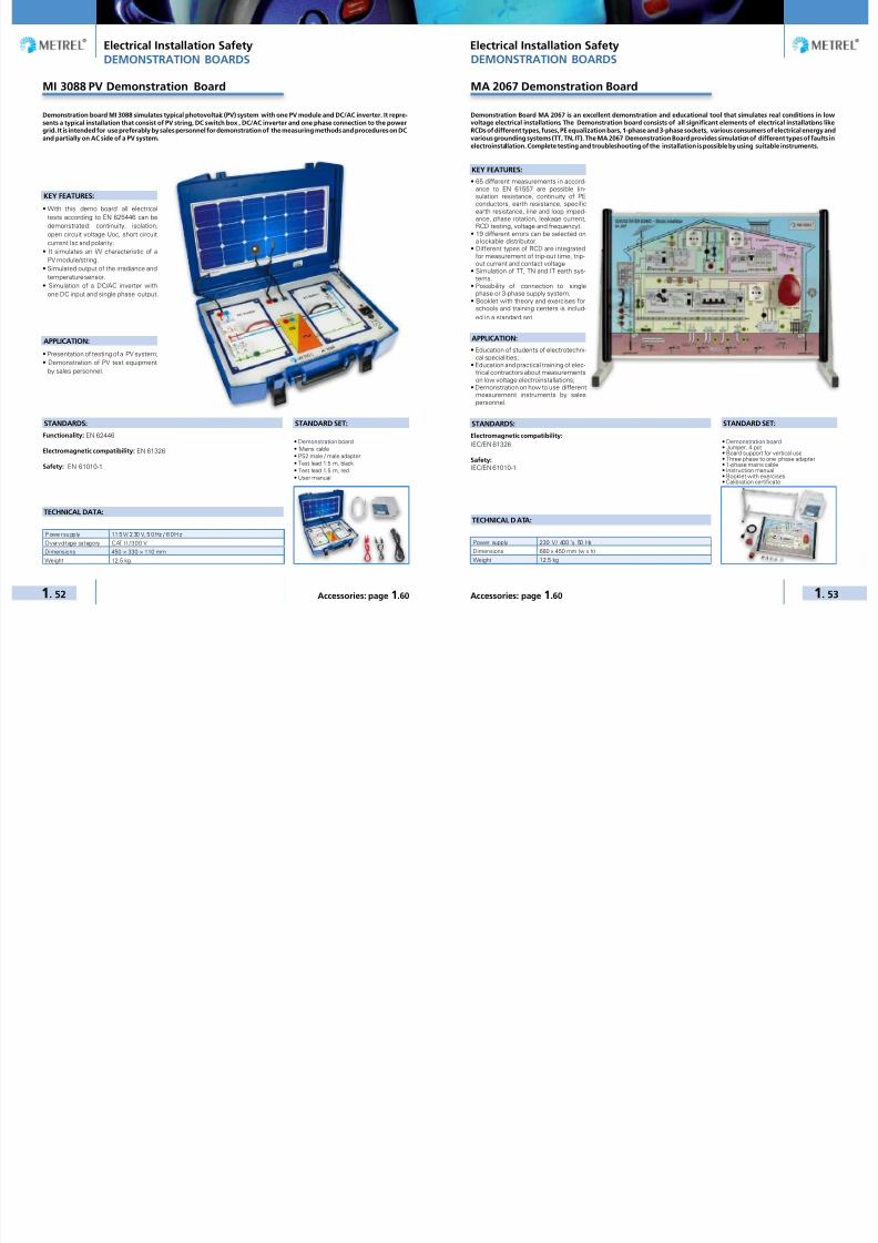
7/25/2019 METREL General Catalog Engl 2015
http://slidepdf.com/reader/full/metrel-general-catalog-engl-2015 30/121
Electrical Installation Safety Electrical Installation Safety
1. 52 1. 53Accessories: page 1.60 Accessories: page 1.60
DEMONSTRATION BOARDS
MI 3088 PV Demonstration Board
KEY FEATURES:
• With this demo board all electricaltests according to EN 625446 can bedemonstrated: continuity, isolation,open circuit voltage Uoc, short circuitcurrent Isc and polarity.
• It simulates an I/V characteristic of aPV module/string.
• Simulated output of the irradiance andtemperature sensor.
• Simulation of a DC/AC inverter withone DC input and single phase output.
APPLICATION:
• Presentation of testing of a PV system;• Demonstration of PV test equipment
by sales personnel.
Demonstration board MI 3088 simulates typical photovoltaic (PV) system with one PV module and DC/AC inverter. It repre-sents a typical installation that consist of PV string, DC switch box , DC/AC inverter and one phase connection to the powergrid. It is intended for use preferably by sales personnel for demonstration of the measuring methods and procedures on DCand partially on AC side of a PV system.
• Demonstration board• Mains cable• PS2 male / male adapter• Test lead 1.5 m, black• Test lead 1.5 m, red• User manual
STANDARD SET:
TECHNICAL DATA:
P owe r su pp ly 11 5 V/ 2 30 V, 5 0 Hz / 6 0 H z
Overvoltage category CAT II / 300 V
Dimensions 450 × 330 × 110 mm
Weight 12.5 kg
STANDARDS:Functionality: EN 62446
Electromagnetic compatibility: EN 61326
Safety: EN 61010-1
MA 2067 Demonstration Board
KEY FEATURES:
• 65 different measurements in accord-ance to EN 61557 are possible (in-sulation resistance, continuity of PEconductors, earth resistance, specific
earth resistance, line and loop imped-ance, phase rotation, leakage current,RCD testing, voltage and frequency).
• 19 different errors can be selected ona lockable distributor.
• Different types of RCD are integratedfor measurement of trip-out time, trip-out current and contact voltage
• Simulation of TT, TN and IT earth sys-tems.
• Possibility of connection to singlephase or 3-phase supply system.
• Booklet with theory and exercises forschools and training centers is includ-ed in a standard set.
APPLICATION:
• Education of students of electrotechni-cal specialities;
• Education and practical training of elec-trical contractors about measurementson low voltage electroinstallations;
• Demonstration on how to use differentmeasurement instruments by salespersonnel.
Demonstration Board MA 2067 is an excellent demonstration and educational tool that simulates real conditions in lowvoltage electrical installations. The Demonstration board consists of all significant elements of electrical installations likeRCDs of different types, fuses, PE equalization bars, 1-phase and 3-phase sockets, various consumers of electrical energy andvarious grounding systems (TT, TN, IT). The MA 2067 Demonstration Board provides simulation of different types of faults inelectroinstallation. Complete testing and troubleshooting of the installation is possible by using suitable instruments.
• Demonstration board• Jumper, 4 pcs• Board support for vertical use• Three phase to one phase adapter• 1-phase mains cable• Instruction manual• Booklet with exercises• Calibration certificate
STANDARD SET:
TECHNICAL DATA:
Power supply 230 V / 400 V, 50 Hz
Dimensions 680 x 450 mm (w x h)
Weight 12.5 kg
STANDARDS:Electromagnetic compatibility:IEC/EN 61326
Safety: IEC/EN 61010-1
DEMONSTRATION BOARDS

7/25/2019 METREL General Catalog Engl 2015
http://slidepdf.com/reader/full/metrel-general-catalog-engl-2015 31/121
Electrical Installation Safety Electrical Installation Safety
1. 54 1. 55Accessories: page 1.60 Accessories: page 1.60
DEMONSTRATION BOARDS
MI 3099 Demonstration Board
KEY FEATURES:
• The board contains real elements ofelectrical installation like RCD, mainsswitch, automatic fuses, switches,lamps, 1-phase and 3-phase mains testoutlet, N and PE collector.
• All standardised testing methods canbe presented.
• TN or TT system with or without RCDcan be simulated.
• Possibility of connection to singlephase or 3-phase supply system.
• Various Autosequence test proceduresare supported for demonstration oftesting safety by new EurotestAT andEurotestXA.
• Demonstration board is put in thestrong rugged case with a handle forcomfortable carrying.
APPLICATION:
• Presentation of complete testing ofany electrical installation;
• Demonstration of electrical installationtest equipment operation by sales per-
sonnel.
STANDARDS:Electromagnetic compatibility:
IEC/EN 61326
Safety:
IEC/EN 61010-1
Demonstration board MI 3099 simulates typical electrical installation usually met in individual houses or apartmentswith important elements on switchboard and on circut site. Demonstration board is intended for use preferably by salespersonnel when demonstrating operation of electrical installation test equipment, especially the new Metrel’s electricallyinstallations safety testers with built-in AUTOSEQUENCE procedure.
• Demonstration board• Jumper• Special probe, 3 pcs• Mains cable• Three phase to one phase adapter• Instruction manual• Calibration certificate
STANDARD SET:
TECHNICAL DATA:
Power supply 230 V / 400 V, 50 Hz
Overvoltage category CAT II / 300 V
Dimensions 480 × 387 × 136 mm
Weight 5 kg
DEMONSTRATION BOARDS
MI 2166 Demonstration Board
KEY FEATURES:
• A number of different measurementsin accordance to EN 61557 are possi-ble (insulation resistance, continuity ofPE conductors, earth resistance (four-
lead and two clamp methods), specificearth resistance, line and loop imped-ance, phase rotation, load current, RCDtesting, contact voltage, etc.).
• Real elements of electrical installationare placed on the front panel like RCD,ON/OFF switch with lamp, mains testoutlet and connection terminals.
• All standardised testing methods canbe presented.
• 5 different errors can be preset by»fault« switches.
• TN or TT system can be simulated.• Demonstration board is put in the
strong rugged case with a handle forcomfortable carrying.
APPLICATION:
• Presentation of complete testing ofany electrical installation;
• Demonstration of electrical installationtest equipment operation by sales per-sonnel.
STANDARDS:
Electromagnetic compatibility: IEC/EN 61326Safety: IEC/EN 61010-1
Demonstration board MI 2166 simulates common electrical installation usually met in individual house or apartment.Demonstration board is to be used preferably by sales personnel when demonstrating operation of electrical installationtest equipment. Various test methods supported by different test instruments can be presented.
• Demonstration board• Jumper, 2 pcs• Mains cable• Instruction manual• Calibration certificate
STANDARD SET:
TECHNICAL DATA:
Power supply 230 V, 50 Hz
Overvoltage category CAT II / 300 V
Dimensions 450 × 330 × 110 mm
Weight 3.56 kg

7/25/2019 METREL General Catalog Engl 2015
http://slidepdf.com/reader/full/metrel-general-catalog-engl-2015 32/121
Electrical Installation Safety Electrical Installation Safety
1. 56 1. 57Accessories: page 1.60 Accessories: page 1.60
Metrel Electrical Safety Manager
The Metrel Electrical Safety Manager is a common application for management of w ide palette of Metrel’s electrical safetytesters, portable appliance testers, machine testers and industrial safety testers. This application has a unified user in-terface with the new generation of Metrel’s instruments - same view same meaning. It enables the pretreatment for themeasurements, viewing and editing of the measurement results and generation of professional reports. Depending onthe instrument model or type the user can create AUTOSEQUENCEs, custom tests or single tests. They can be integratedinto the custom created test structures and then uploaded into the measurement instrument.
The downloaded measurement resultscan be viewed, analysed, edited andfinally a professional report can be cre-ated and printed. These professional re-ports are predefined templates accord-
ing to national standards and regulatoryorganisations where the user enters allthe needed protocol data while themeasurement results are automaticallyinserted into the predefined forms. Thisapplication is fully compatible with thenew generation of Metrel’s multifunctiontesters, starting with CE MultitesterXAand EurotestXC. With limited functional-ity some of the predecessor models likeEurotestXE or EurotestCombo are alsosupported.
KEY FEATURES:
• Common platform f or wide rangeof Metrel’s instruments: a Windowsbased application for most of the fu-ture Metrel’s instruments.
• Multilevel test structure editor: theinstallation structure can be created inadvance on the PC and then simply up-loaded to your tester.
• Measurement editor: enables defini-tion of tests within the test structurewith all parameters and sub parame-
ters. After the structure is uploaded tothe instrument, such predefined testcan be selected and started withoutadditional settings.
• AUTOSEQUENCE editor: applicationfor easy and efficient preparation ofAUTOSEQENCEs or custom tests.
• Report creator: enables automaticgeneration of professional test reportswhich include visual inspection of testedobject and test results in tabular form.
• Multilingual reports according to lo-cal regulations: different languages
for the application and reporting are
supported
• Export of test results: test results intext (.csv) or .xml format can be ex-ported to other programs.
PC SOFTWARE PC SOFTWARE
The EuroLink PRO / PRO Plus software works in conjunction with Metrel’s downloadable installation testers. The softwareautomatically finds the instrument and allows the test engineer to download test results saved on the instrument, reviewthe results, relocate test results (if required), print test reports and print installation structures for storing in the distribu-tion board. With the more advanced Metrel installation testers, structures can be built with the software and uploadedto the instrument for easy installation navigation while performing on-site testing. Additionally the EuroLink PRO Plussoftware offers the ability to automatically generate professional PRO Plus Reports.
KEY FEATURES:
• Automatic recognition of the instru-ment: when connecting your instru-ment to the PC it is automatically rec-ognized by the software.
• Simple graphical visualisation of theinstallation structure: enables graphi-cal representation of the tested instal-lation which makes it easy to navigatein the installation.
• 10-level structures: in conjunctionwith MI 3105 and MI 3101 PC soft-ware enables creating the electricalinstallation structures with up to 10levels and 4 levels for other models.
• Rearranging of structures: the ele-ments of the structure can be relocat-ed and renamed.
• Installation structures printing: struc-tures can be printed and stored in thedistribution board for easier later iden-tification of the installation elements.
• Structures upload: the installationstructure can be created in advanceon the PC and then simply uploadedto your tester MI 3108, MI 3109, MI3105, MI 3101, MI 3102H CL, MI3102H BT, MI 3102 BT, MI 3100 SE,MI 3125 BT and MI 3125B.
• Export of test results: test results intext format can be exported to otherprograms (MS Excel, MS Word).
• Automatic PRO Test Report genera-tion: enables automatic generation ofPRO Test Report (low, medium andhigh detailed).
• Automatic PRO Plus Test Reportgeneration (PRO Plus version only):enables automatic generation of PROPlus Test Report which include visualinspection of tested object and test re-sults in tabular form.
• Suport of EuroLink Android: suportsextended file format from EuroLink An-droid App.
PC SW EuroLink PRO / PRO Plus is com-patible with:• MI 3108, MI 3109, MI 3105, MI 3101,
MI 3102, MI 3102H CL, MI 3102H BT,
MI 3102 BT, MI 3100 SE, MI 3002,MI 3125 BT, MI 3125B, MI 3121, MI3121H, MI 3122 and MI 3123.
Key features of PRO Plus Test Reports:• Downloaded test results are automat-
ically inserted onto PRO Plus forms.
• Allows to fill out visual inspectionform for tested fuse cabinet or earth-ing system.
• Automatically selects worst case testresults for form completion.
• Easy test report generation and re-viewing facilities.
Eurolink PRO Plus enables creation ofthe following test reports:• PRO Plus Test Report• NICEIC certificates (UK)• ZVEH certificates (Germany)• SiNa certificates (Switzerland)• ÖVE certificates (Austria)• HD 384 certificates (Greek)• KEHE certificates (Greek)
• GOST R 50571 (Russia)• UNE – 202008 certificates (Spain)
PASSWORD PROTECTION:
PC SW EuroLink PRO is password pro-tected for the following instruments:
• MI 3121,• MI 3121H,• MI 3122,• MI 3123.
PC SW EuroLink PRO Plus is passwordprotected for all Metrel installation test-ers.
ORDERING INFORMATION:
• A 1291 PC SW EuroLink PRO withUSB and RS232-PS/2 cable
• A 1290 PC SW EuroLink PRO Pluswith USB and RS232-PS/2 cable
• A 1292 Upgrade code EuroLink PRO toEuroLink PRO Plus
EuroLink PRO and EuroLink PRO Plus

7/25/2019 METREL General Catalog Engl 2015
http://slidepdf.com/reader/full/metrel-general-catalog-engl-2015 33/121
Electrical Installation Safety Electrical Installation Safety
1. 58 1. 59Accessories: page 1.60 Accessories: page 1.60
A 1431 EuroLink Android
PC SOFTWARE
The EuroLink Android is a data management tool for android tablets and smart phones. It is used in the field togetherwith Metrel’s Electrical Installation Safety testers to serve as a measurement pre- and post-processing tool. It also enablesthe wireless communication between instrument and Android device on one side and bunch of wireless communicationmethods between Android device and PC.
KEY FEATURES:
• Create the Reports already at the siteof Testing!
• Attach notes, Photographs, Audio or
Video Files!• Share the Reports or Send them toyour clients!
• Create Structure of Electrical Installa-tion at the site.
• Upload Structure of Electrical Installa-tion to your test instrument
• Download measurement results to Eu-roLink Android Application.
• Transfer Data, Share files or Sendthem through your Tablet or SmartPhone Tools to your Office for furthermanipulation.
• It is compatible with EuroLink PRO andEuroLinkPRO Plus PC software.
• It supports Bluetooth dongle or built-in BT enabling communication channelbetween the below listed measuringinstruments and a smart phone or atablet with Android OS and installedapplication EuroLink Android.
EuroLink Android is compatible with:• MI 3105 EurotestXA
(supported by BT dongle)• MI 3101 EurotestAT(supported by BT dongle)
• MI 3102 BT EurotestXE• MI 3102H BT EurotestXE• MI 3100 SE EurotestEASI
(supported by BT dongle)• MI 3125BT EurotestCOMBO• MI 3108 EurotestPV
(supported by BT dongle)
Transfer Data, Share files or Send themthrough your Tablet or Smart Phone Toolsto your Office for further manipulation.
Create Structure of Electrical Installationat the site.
READY
Supported byBT dongle
Built-in BTsolution
A 1428 EuroLinkPV Android
PC SOFTWARE
The EuroLinkPV Android is a data management tool for android tablets and smart phones. It is used at the site of testingtogether with Metrel’s Photovoltaic testers as a measurement pre- and post-processing tool. It enables the wirelesscommunication between instrument and Android device. With this application testing of PV is more comfortable andeffective.
KEY FEATURES:
• View the results of the I/V measure-ment in graphical or numerical form.
• Compare the results with the nominalvalues and characteristic.
• Edit the module data stored in instrument
memory using the Android Keyboard.• Edit the module list stored in instru-
ment memory.• The module data can be selected from the
huge module Data Base delivered within
the EuroLinkPV Android application.
• It supports Bluetooth dongle enablinga communication channel between thebelow listed measuring instrumentsand a smart phone or a tablet with An-droid OS and installed application Eu-roLinkPV Android.
EuroLink Android is compatible with:• MI 3108 EurotestPV
(supported by BT dongle)• MI 3109 EurotestPV Lite
(supported by BT dongle)
READY
Supported byBT dongle
Built-in BTsolution

7/25/2019 METREL General Catalog Engl 2015
http://slidepdf.com/reader/full/metrel-general-catalog-engl-2015 34/121
Electrical Installation Safety Electrical Installation Safety
1. 60 1. 61Accessories: page 1.60 Accessories: page 1.60
Selection Guide for EIS Accessories
Option – Not available
PhotoPart
numberDescription Target app li cat ion
M I 3 1 0 8
M I 3 1 0 9
M I 3 1 5 2
M I 3 1 0 5
M I 3 1 0 1
M I 3 1 0 2 H B T
M I 3 1 0 2 B T
M I 3 1 0 0 S E
M I 3 1 0 0 s
M I 3 1 2 5 B T
M I 3 1 2 5
M I 2 0 8 6
M I 2 0 8 8
M I 3 1 2 1
M I 3 1 2 2
M I 3 1 2 3
M I 3 1 1 0
M I 2 1 2 6
M I 3 1 0 3
M I 2 0 9 3
A 1 1 4 3
A 1143 Euro Z 290 A
Euro Z 290 A is the impedance testerwhich enables line / loop impedancemeasurements with an accuracy downto 0.1 mΩ.
– – – – – – – – – – – – – – – – –
A 1199 Ro-adapterRo-adapter is intended for performingearth resistance measurement in com-bination with installation safety tester.
– – – – – – – – – – – – – – – –
A 1378EurotestPVRemote
PV remote unit for measurement andlogging of irradiance and temperaturevalues
– – – – – – – – – – – – – – – – – – –
A 1384 PV Safety ProbeThe PV safety probe can safely discon-nect the PV installation from the installa-tion in case of a permanent short circuit.
– – – – – – – – – – – – – – – – – – –
CS 2099 EurocheckEurocheck is a professional multifunc-tional field calibrator intended for usewith installation safety testers.
– – – – –
A 1160
Fast charger for 8AA batteries witha set of 6 NiMHbat., type AA
Fast battery charger for up to 8 piecesof AA rechargeable batteries, and a setof 6 pcs NiMH rechargeable batteries,type AA.
– – – – –
A 1169Fast charger forAA, C, D and 9 Vblock batteries
Fast battery charger for up to 12 pcs AA,6 pcs C or D rechargeable batteries, 4pcs 9 V block batteries.
–
A 1083
Power supplyadapter with 6 pcsNiMH batteries,type AA
Battery charger and a set of 6 pieces ofrechargeable batteries, type AA.
– – – – – –
A 1427 PV Reference Cell Irradiance sensor for PV measurements. – – – – – – – – – – – – – – – – – – –
A 1400PV Temperatureprobe
Temperature probe for measurement ofPV module temperature.
– – – – – – – – – – – – – – – – – – –
A 1102Luxmeter sensor,type B
Luxmeter sensor, type B, for high-accu-racy illuminance measurement.
– – – – – – – – – – – – – – – – – – – –
A 1119Luxmeter sensor,type C
Luxmeter sensor, type C, for illuminancemeasurement e.g. for general light con-ditions testing.
– – – – – – – – – – – – – – – – – – – –
Selection Guide for EIS Accessories
Option – Not available
PhotoPart
numberDescription Target app li cat ion
M I 3 1 0 8
M I 3 1 0 9
M I 3 1 5 2
M I 3 1 0 5
M I 3 1 0 1
M I 3 1 0 2 H B T
M I 3 1 0 2 B T
M I 3 1 0 0 S E
M I 3 1 0 0 s
M I 3 1 2 5 B T
M I 3 1 2 5
M I 2 0 8 6
M I 2 0 8 8
M I 3 1 2 1
M I 3 1 2 2
M I 3 1 2 3
M I 3 1 1 0
M I 2 1 2 6
M I 3 1 0 3
M I 2 0 9 3
A 1 1 4 3
A 1172Luxmeter sensor,type B (PS/2)
Luxmeter sensor, type B, for high-accu-racy illuminance measurement e.g. foremergency lightning inspection.
– – – – – – – – – – – – – – – – –
A 1173Luxmeter sensor,type C (PS/2)
Illuminance probe for light conditionsmeasurements with 0,1Lux resolution.
– – – – – – – – – – – – – – – – –
A 1005Fuse / fault / cablelocator
Fuse / fault / cable locator is used forwire tracing, fuse identification and faultfinding in low voltage electrical installa-tions.
– – – – – – – – – – – – – – – – – – – –
A 1191 Receiver R10KReceiver R10K is used for wire tracing,fuse identification and fault finding inlow voltage electrical installations.
– – – – – – – – – – – – – – – – – – –
A 1192Selective probe forR10K
Very sensitive inductive sensor servesfor contactless fuse and cable finding.To be used with A 1191.
– – – – – – – – – – – – – – – – – –
A 1067Test lead for R10K,1.5 m, with built-inresistor
Test lead with probe enables fast andaccurate fuse finding and current circuitallocation. To be used with A 1191.
– – – – – – – – – – – – – – – – – –
A 1168Plug commander(for MI 3125 <HW3)
Single phase schuko plug commanderwith TEST and BACKLIGHT functionkeys for fast and simple measurementson one phase sockets.
– – – – – – – – – – – – – – – – – – – –
A 1256Plug commander(straight cable)
Single phase schuko plug commanderwith TEST and MEM function keys forfast and simple measurements on onephase sockets.
– – – – – – – – – – – – – – – – –
A 1170 Plug commander
Single phase schuko plug commanderwith TEST and MEM function keys forfast and simple measurements on onephase sockets.
– – – – – – – – – – – – – – – – – – –
A 1272Plug commander(for Smartec)
Single phase schuko plug commanderwith TEST and MEM function keys forfast and simple measurements on onephase sockets.
– – – – – – – – – – – – – – – – – – – –
A 1314 Plug commander
Single phase, 3-wire, commander withTEST and MEM function and RGBLED indicator for easy insulation safetymeasurements for use with MI 3108and its successors.
– – – – – – – – – – – – –
A 1401 Tip commander
Single phase, 3-wire, commander withTEST and MEM function and RGBLED indicator for easy insulation safetymeasurements for use with MI 3108and its successors.
– – – – – – – – – – – – –

7/25/2019 METREL General Catalog Engl 2015
http://slidepdf.com/reader/full/metrel-general-catalog-engl-2015 35/121
Electrical Installation Safety Electrical Installation Safety
1. 62 1. 63Accessories: page 1.60 Accessories: page 1.60
Selection Guide for EIS Accessories
Option – Not available
PhotoPart
numberDescription Target app li cat ion
M I 3 1 0 8
M I 3 1 0 9
M I 3 1 5 2
M I 3 1 0 5
M I 3 1 0 1
M I 3 1 0 2 H B T
M I 3 1 0 2 B T
M I 3 1 0 0 S E
M I 3 1 0 0 s
M I 3 1 2 5 B T
M I 3 1 2 5
M I 2 0 8 6
M I 2 0 8 8
M I 3 1 2 1
M I 3 1 2 2
M I 3 1 2 3
M I 3 1 1 0
M I 2 1 2 6
M I 3 1 0 3
M I 2 0 9 3
A 1 1 4 3
A 1002 Tip commander
Single phase 2-wire commander withtest tip and START and SAVE functionkeys for installation safety measure-ments.
– – – – – – – – – – – – – – – – – – – –
A 1176 Tip commander
Single phase 2-wire commander withtest tip and TEST and MEM functionkeys for installation safety measure-ments.
– – – – – – – – – – – – – – – – – – –
A 1197Tip commander,3-wire
Single phase 3-wire commander withtest tip, TEST and MEM function keysfor installation safety measurements.
– – – – – – – – – – – – – – – – – – –
A 1244Tip commander,2-wire (straightcable)
Single phase 2-wire commander withtest tip, TEST and SAVE function keysfor installation safety measurements.
– – – – – – – – – – – – – – – –
A 1270Tip commander(for Smartec)
Single phase 2-wire commander withtest tip, TEST and MEM function keysfor installation safety measurements.
– – – – – – – – – – – – – – – – – – –
A 1300Tip commander,3-wire (forSmartec)
Single phase 3-wire commander withtest tip, TEST and MEM function keysfor installation safety measurements.
– – – – – – – – – – – – – – - – – – – –
A 1018Current clamp (lowrange, leakage)
High accuracy current clamp 1000 A / 1 A
with jaw opening 52 mm and fixed 1.5 mcable for both load and low range / leak-age current measurement and for earth
resistance measurement as well.
– – – – – – – – – – – –
A 1019 Current clamp
Current clamp 1000 A / 1 A with jaw open-ing 52 mm for general current measure-ments and in combination with A 1018for earth resistance measurement with-out breaking the loop.
– – – – – – – – – – – – –
A 1068Connection cablefor clamp, 1.5 m
Connection cable for connecting currentclamp on the instrument MI 2093.
– – – – – – – – – – – – – – – – – – – –
A 1074Mini current clamp200 A / 0.2 A
Mini current clamp 200 A / 0.2 A withjaw opening 15 mm for current meas-urement in confined spaces.
– – – – – – – – – – – – – –
A 1391AC/DC Currentclamp
AC/DC Current Clamp with 40 and 300A range.
– – – – – – – – – – – – – – – –
A 1011Test lead, 3 x1.5 m
3-wire test lead for measurements onsingle or three phase electrical installa-tions.
– – – – – – – –
Selection Guide for EIS Accessories
Option – Not available
PhotoPart
numberDescription Target app li cat ion
M I 3 1 0 8
M I 3 1 0 9
M I 3 1 5 2
M I 3 1 0 5
M I 3 1 0 1
M I 3 1 0 2 H B T
M I 3 1 0 2 B T
M I 3 1 0 0 S E
M I 3 1 0 0 s
M I 3 1 2 5 B T
M I 3 1 2 5
M I 2 0 8 6
M I 2 0 8 8
M I 3 1 2 1
M I 3 1 2 2
M I 3 1 2 3
M I 3 1 1 0
M I 2 1 2 6
M I 3 1 0 3
M I 2 0 9 3
A 1 1 4 3
A 1021 Test lead, 4 x 1 m4-wire test lead for measurements onelectrical installations.
– – – – – – – – – – – – – – – – – – –
A 1055Test lead, 2 x1.5 m
2-wire test lead for continuity and insula-tion resistance measurements on elec-trical installations.
– – – – – – – – – – – – – – – – – – – –
A 1385 PV fused test leadTest cable for simultaneous AC/DCpower and efficiency measurements ofPV inverters.
– – – – – – – – – – – – – – – – – – –
S 2001Earth test set,4-wire, 20 m
Earth test set for earth resistance meas-urement on distance up to 20 m; setincludes: test lead, 4 x 1 m; test lead,20 m, 2 pcs; test lead, 4 m, 2 pcs; earthspikes, 4 pcs; soft carrying bag.
– – – – – – – – – – – – – – – – – – –
S 2002Earth test set,4-wire, 50 m
Earth test set for earth resistance meas-urement on distance up to 50 m; set in-
cludes: test lead, 4 x 1 m; test lead, 50 m,2 pcs; test lead, 4 m, 2 pcs; test lead, 1 m,
2 pcs; earth spikes, 4 pcs; carrying bag.
– – – – – – – – – – – – – – – – – – –
S 2041Earth test set,4-wire, 50 m (forSmartec)
Earth test set for earth resistance meas-urement on distance up to 50 m; set in-cludes: test lead, 50 m, 2 pcs; test lead,4 m, 2 pcs; test lead, 1 m, 2 pcs; earthspikes, 4 pcs; soft carrying bag.
– – – – – – – – – – – – – – – – – – – –
S 2026Earth test set,3-wire, 20 m
Earth test set for earth resistance meas-urement on distance up to 20 m; set in-cludes: test lead, 20 m, 2 pcs; test lead,4.5 m; earth spikes, 2 pcs; soft carryingbag.
– – – – – – – – – – – –
S 2027Earth test set,3-wire, 50 m
Earth test set for earth resistance meas-urement on distance up to 50 m; setincludes: test lead, 50 m, 2 pcs; testlead, 4.5 m; test lead, 1 m, 2 pcs; earthspikes, 2 pcs; soft carrying bag.
– – – – – – – – – – –
S 2058Insulation testplates
Two in one: Test plates for measure-ment of floor and wall insulation, ∆625cm2 (acc. to EN 60364-6) and measure-ment of semi conductivity, 2,5 kg, Ø65mm (acc. to EN 61340-5-1).
– – – – – – –
A 1052PC SW EuroLinkPRO (for MI 2086)
EuroLink PRO is a professional PC Soft-ware which enables downloading, datamanagement and complete test reportpreparation.
– – – – – – – – – – – – – – – – – – – –
A 1290
PC SW EuroLinkPRO Plus withUSB and RS232-PS/2 cable
Professional PC Software EuroLinkPRO Plus enables downloading, datamanagement and complete test reportpreparation. Delivered with RS232-PS/2 and USB communication cables.
– – – – – – – – – – – – – – – – – –
A 1291PC SW EuroLinkPRO with USB andRS232-PS/2 cable
PC Software EuroLink PRO enablesdownloading and test results manage-ment and printing of test reports. Deliv-ered with RS232-PS/2 and USB communi-cation cables.
– – – – – – – – – – – – – – – – – –

7/25/2019 METREL General Catalog Engl 2015
http://slidepdf.com/reader/full/metrel-general-catalog-engl-2015 36/121
Electrical Installation Safety Electrical Installation Safety
1. 64 1. 65Accessories: page 1.60 Accessories: page 1.60
Selection Guide for EIS Accessories
Option – Not available
PhotoPart
numberDescription Target app li cat ion
M I 3 1 0 8
M I 3 1 0 9
M I 3 1 5 2
M I 3 1 0 5
M I 3 1 0 1
M I 3 1 0 2 H B T
M I 3 1 0 2 B T
M I 3 1 0 0 S E
M I 3 1 0 0 s
M I 3 1 2 5 B T
M I 3 1 2 5
M I 2 0 8 6
M I 2 0 8 8
M I 3 1 2 1
M I 3 1 2 2
M I 3 1 2 3
M I 3 1 1 0
M I 2 1 2 6
M I 3 1 0 3
M I 2 0 9 3
A 1 1 4 3
A 1292Upgrade codeEuroLink PRO toEuroLink PRO Plus
Password for upgrading standard PC soft-ware EuroLink PRO to advanced PC SWEuroLink PRO Plus with professional re-port creation facility.
– – – – – – – – –
P 1001Licence key foradvanced MESManager
Licence key for upgrading the MES Man-ager to advanced version with profession-al report creation functionality
– – – – – – – – – – – – – – – – – – – –
A 1431EuroLink AndroidAPP
EuroLink Android APP – – – – – – – – – – – – – – –
A 1012Test lead, green,4 m
Extension test lead for continuity meas-urements.
– – – – – – – –
A 1154Test lead, black,4 m
Extension test lead for earth and conti-nuity measurements.
– – – – – –
A 1026Test lead, red,20 m
Extension test lead for continuity meas-urements.
– – – – – –
A 1153Test lead, black,20 m
Extension test lead for earth and conti-nuity measurements.
– – – – – –
A 1164Test lead, black,50 m
Extension test lead for earth and conti-nuity measurements.
– – – – – –
S 2009Test lead set, 2 m,4 pcs
Set of 4 test leads is intended for twoclamp earth resistance measurement toconnect current clamps on the instru-ment.
– – – – – – – – – – – – – – – – – – – –
S 2012Continuity testlead, 10 m, 2 pcs(red, black)
2 pieces of extension test lead for conti-nuity measurements.
– – – – –
S 2025Test lead, 1.5 m,2 pcs (black, red)
Connection leads for different measure-ments.
– – – – –
A 1013Crocodile clip,black
Crocodile clip assures secure and per-manent contact during the measure-ment on bus bars, fixing screws, etc.
– – – – – –
Selection Guide for EIS Accessories
Option – Not available
PhotoPart
numberDescr ipt ion Target app li ca tion
M I 3 1 0 8
M I 3 1 0 9
M I 3 1 5 2
M I 3 1 0 5
M I 3 1 0 1
M I 3 1 0 2 H B T
M I 3 1 0 2 B T
M I 3 1 0 0 S E
M I 3 1 0 0 s
M I 3 1 2 5 B T
M I 3 1 2 5
M I 2 0 8 6
M I 2 0 8 8
M I 3 1 2 1
M I 3 1 2 2
M I 3 1 2 3
M I 3 1 1 0
M I 2 1 2 6
M I 3 1 0 3
M I 2 0 9 3
A 1 1 4 3
A 1064 Crocodile clip, redCrocodile clip assures secure and per-manent contact during the measure-ment on bus bars, fixing screws, etc.
– – – – – – – – – – – – – – – – –
A 1309Crocodile clip,green
Crocodile clip assures secure and per-manent contact during the measure-ment on bus bars, fixing screws, etc.
– – – – – – – – – –
A 1310 Crocodile clip, blueCrocodile clip assures secure and per-manent contact during the measure-ment on bus bars, fixing screws, etc.
– – – – – – – – – –
A 1014 Test probe, black
Test probe with ∅ 4 mm connection issuitable for performing measurementsboth in mains outlets and in situationswhen no schuko outlet is present.
– – – – – –
A 1015 Test probe, blue
Test probe with ∅ 4 mm connection issuitable for performing measurementsboth in mains outlets and in situationswhen no schuko outlet is present.
– – – – – – – –
A 1016 Test probe, red
Test probe with ∅ 4 mm connection issuitable for performing measurementsboth in mains outlets and in situationswhen no schuko outlet is present.
– – – – – – – – – – – – – – – –
A 1062 Test probe, green
Test probe with ∅ 4 mm connection issuitable for performing measurementsboth in mains outlets and in situationswhen no schuko outlet is present.
– – – – – – – –
A 1198Magnetic contactprobe
Test probe with magnetic contact pro-vides reliable contact with metal surfaceduring the measurement.
– – – – –
A 1201Insulated rod forCONTINUITYmeasurement
Insulated rod enables insulation resist-ance and continuity measurement onhard-to-reach objects, e.g. luminaries.
– – – – – –
A 1202Additional exten-sion part for A1201
Additional extension part for Insulatedrod for CONTINUITY measurement A1201.
– – – – – –
A 1006 Soft carrying bagLarge soft carrying bag for transport andstorage of test instrument and belong-ing accessories.
– – – – – – – – – – – – – – – – – – –
A 1289 Soft carrying bagLarge soft carrying bag for transport andstorage of test instrument and belong-ing accessories.
– – – – – – – –

7/25/2019 METREL General Catalog Engl 2015
http://slidepdf.com/reader/full/metrel-general-catalog-engl-2015 37/121
Electrical Installation Safety Electrical Installation Safety
1. 66 1. 67Accessories: page 1.60 Accessories: page 1.60
Option – Not available
PhotoPart
numberDescription Target app li cat ion
M I 3 1 0 8
M I 3 1 0 9
M I 3 1 5 2
M I 3 1 0 5
M I 3 1 0 1
M I 3 1 0 2 H B T
M I 3 1 0 2 B T
M I 3 1 0 0 S E
M I 3 1 0 0 s
M I 3 1 2 5 B T
M I 3 1 2 5
M I 2 0 8 6
M I 2 0 8 8
M I 3 1 2 1
M I 3 1 2 2
M I 3 1 2 3
M I 3 1 1 0
M I 2 1 2 6
M I 3 1 0 3
M I 2 0 9 3
A 1 1 4 3
A 1020Small soft carryingbag
Small soft carrying bag for transport andstorage of test instrument or accesso-ries.
– – – – – – – – – – – – – – – – – – – –
A 1271Small soft carryingbag
Small soft carrying bag for transport andstorage of test instrument or accesso-ries.
– – – – – – – – – – – – – – – –
A 1302Set of carryingstraps
Set of carrying straps for carrying themeasuring instrument around the neckallowing free hand use of the tester.
– – – – – – – – – – – – – – – –
A 1303 Soft hand strapSoft hand strap for holding the instru-ment.
– – – – – – – – – – – – – – – –
A 1110Three phaseadapter
3-phase test adapter for installationsafety testing on 3-phase sockets type16 A 3CEE.
– – – – – – – – –
A 1111A 1215
Three phaseadapter withswitch
3-phase adapter with selection switchfor installation safety testing on 3-phasesockets type 16 A 3CEE. The adapterallows seamless switching betweenmeasurements.
– – – – – – – – –
A 1171RS232 / USBadapter with 1 mcable
RS232 / USB adapter for instrumentswithout USB comunication port.
– – – – – – – – – – – – – – – – – – –
A 1436 Bluetooth dongle
External Bluetooth adapter for wirelessconnection between Metrel’s instru-ments and Smart phones, tablets andPCs.
– – – – – – – – – – – – – – – –
A 1017Communicationcable RS232
RS232 interface cable for connectingthe instrument with the PC.
– – – – – – – – – – – – – – – – – – –
A 1105 Barcode scanner
Barcode scanner for identification ofbarcode labelled installation structureelements like sockets, switches, fuses,switchboards, etc.
– – – – – – – – – – – – – – – –
AM 133 7 RF ID Re ad er RF ID re ad er – – – – – – – – – – – – – – – – – – –
S 2055Set of 2 flat con-tact clamps
Flat contact clamp with integrated fusefor a fast and safe contact on flat con-ductor bars, eg. in low voltage installa-tions. With red-colored ring.
– – – – – – – – – – – – – – – – – – – –
Selection Guide for EIS Accessories Selection Guide for EIS Accessories
PhotoPart
numberDescription Target app li cat ion
M I 3 1 0 8
M I 3 1 0 9
M I 3 1 5 2
M I 3 1 0 5
M I 3 1 0 1
M I 3 1 0 2 H B T
M I 3 1 0 2 B T
M I 3 1 0 0 S E
M I 3 1 0 0 s
M I 3 1 2 5 B T
M I 3 1 2 5
M I 2 0 8 6
M I 2 0 8 8
M I 3 1 2 1
M I 3 1 2 2
M I 3 1 2 3
M I 3 1 1 0
M I 2 1 2 6
M I 3 1 0 3
M I 2 0 9 3
A 1 1 4 3
S 2056 RFID HGLFlat contact clamp for a fast and safecontact on flat conductor bars, eg. inlow voltage installations.
– – – – – – – – – – – – – – – – – – – –
S 2057Set 5 of crocodileclips
Set of 3 black and 2 r ed crocodile clips,which assures secure and permanentcontact during the measurement on busbars, fixing screws, etc.
– – – – – – – – – – – – – – – – – – – –
Option – Not available

7/25/2019 METREL General Catalog Engl 2015
http://slidepdf.com/reader/full/metrel-general-catalog-engl-2015 38/121
Accessories: page 2.33
Electrical Installation Safety
1. 68 Accessories: page 1.60
M e t r e l w o r k i n g t e a m
f o r t h e a b s o l u t e p o l e p o s i t i o n
.
GOOD TO KNOWHigh Voltage Insulation / Continuity / Earth 2 - 02
Selection Guide for CONTINUITY Insulation Testers 2 - 06Selection Guide for HV Insulation Testers 2 - 07EARTH TESTER
MI 3295 Step Contact Voltage Measuring System 2 - 08CONTINUITY TESTERS
MI 3252 MicroOhm 100A 2 - 10MI 3250 MicroOhm 10A 2 - 12MI 3242 MicroOhm 2A 2 - 14
HIGH VOLTAGE INSULATION TESTERS
MI 3210 TeraOhmXA 10 kV 2 - 16MI 3200 TeraOhm 10 kV 2 - 18
MI 3205 TeraOhmXA 5 kV 2 - 20MI 3201 TeraOhm 5 kV Plus 2 - 22MI 2077 TeraOhm 5 kV 2 - 24
MI 3202 GigaOhm 5 kV 1 - 26MI 3121H 2,5 kV Insulation / Continuity 2 - 28
PC SOFTWAREHVLink PRO 2 - 30
DEMONSTRATION BOARDMI 3299 HV demo BOX 2 - 32
Selection Guide for HV Accessories 2 - 33
H i g h V o l t a g e I n s u l a t i o n / C o n t i n u i t y / E a r t h
H i g h V o l t a g e I n s u l a t i o n R e s i s t a n c e D i a g n o s t i c s
/ A c c u r a t e L o w R
e s i s t a n c e M e a s u r e m e n t sMEASURING INSTRUMENTS AND TESTERS
High Voltage Insulation / Continuity / Earth
CATALOGUE 2015

7/25/2019 METREL General Catalog Engl 2015
http://slidepdf.com/reader/full/metrel-general-catalog-engl-2015 39/121

7/25/2019 METREL General Catalog Engl 2015
http://slidepdf.com/reader/full/metrel-general-catalog-engl-2015 40/121
High Voltage Insulation / Continuity / Earth High Voltage Insulation / Continuity / Earth
2. 4 2. 5Accessories: page 2.33 Accessories: page 2.33
GOOD TO KNOW GOOD TO KNOW
HV, Step / Contact Voltage and Earth Resistance HV, Step / Contact Voltage and Earth Resistance
I
I i
I i
I i
0 t0
U
Ustart
Varistor
breakedown
Defective
insulation
Ub
Measuring procedure for withstanding voltage measure-
ment.
Typical connections for:
Power cables
Measurement of insulation resistance of cable between one
conductor against other conductors including lead sheath
Measurement of insulation resistance of cable between one
conductor against other conductors and lead sheath using
the guard terminal to avoid leakage effects at the end of
cable
Measurement of insulation resistance of a cable between a
conductor and lead sheath
Control and communication cable
Measurement of insulation resistance between one lead of
communication cable against other leads and sheath
Measurement of insulation resistance of communication
cable using the guard terminal. Resistance is measured be-
tween a lead and sheath
Measurement of insulation resistance of communication
cable using the guard terminal. Resistance is measured be-
tween one lead and other leads
Home appliances and similar electrical
devices
Measurement of household device, protection class I and
class II
Induction motor
Measurement of insulation resistance of induction motor
between all three phases against metal enclosure
Power transformer
The simplest measurement of insulation resistance of trans-
former
Measurement of insulation resistance on one HV winding
against metal enclosure
Earthing
Correct earthing of exposed conductiveparts of the object assures that the volt-age on them stays below dangerouslevel in case of a fault. If fault happens a
fault current will flow through the earth-ing electrode.
A typical voltage distribution occursaround the electrode (the “voltage fun-nel”). Fault currents close to power dis-tribution objects (substations, distribu-
tion towers, plants) can be very high, upto 200 kA. This can result in dangerousstep and contact voltages. If there areunderground metal connections (intend-ed or unknown) the voltage funnel canget atypical forms and high voltages canoccur far from the point of failure. There-
fore the voltage distribution in case of afault around this objects must be care-fully analyzed.
Dangerous voltages on a faulty earthing system
Standard IEC 61140 defines following
maximum allowed time / contact volt-
age relations:
Maximum time of exposure Voltage
> 5 s to ∞ UC ≤ 50 VAC or ≤ 120 VDC
< 0.4 s UC ≤ 115 VAC or ≤180 VDC
< 0.2 s UC ≤ 200 VAC
< 0.04 s UC ≤ 250 VAC
Maximum time durations vs fault voltage
For a longer exposure the touch volt-ages must stay below 50 V.
During the measurement a test cur-rent is injected into the earth through
an auxiliary probe. A higher injectedcurrent improves the immunity againstspurious earth currents.
Step voltage measurementThe measurement of step voltage isperformed between two ground pointsat a distance of 1 m. The 25 kg measur-ing probes simulates the feet. The volt-age between the probes is measuredby a voltmeter with an internal resist-ance of 1 kΩ that simulates the bodyresistance.
Step voltage measurement
Contact voltage measurement
The measurement of contact voltage isperformed between an earthed acces-sible metal part and ground. The volt-age between the probes is measuredby a voltmeter with an internal resist-ance of 1 kΩ that simulates the bodyresistance.
Contact voltage measurement
Earth resistance measurementFor the earthing resistance test a voltageand current probe (serves as auxiliaryearth) are used. Because of the voltagefunnel it is important that the test elec-trodes are placed correctly.
Earth resistance measurement
Specific earth resistanceFor the specific earth resistance thetest current is injected through two cur-rent probes (C1/H and C2/E).
The voltage probes S and ES must beplaced between the current probes(equidistance ’a’ between probes mustbe considered). Using different dis-tances between the test probes meansthat the material at different depths ismeasured. By increasing the distances’a’ a deeper layer of ground material ismeasured.
Specific earth resistance measurement
Low Resistance MeasurementFour-wire Kelvin methodWhen measuring resistance <20 Ω it isadvisable to use a four-wire Kelvin meas-urement technique for achieving highaccuracy. By using this type of meas-urement configuration the test lead re-sistance is not included in the measure-ment, and the need for lead calibratingand balancing is eliminated.
Typical connections for:
Circuit breaker connection
Bus bar connection
Connecting instrument to the measured device
The measuring current is passed through
the unknown resistance Rx using the C1
and C2 leads. The placing of these leads
is not critical but should always be out-
side the P1 and P2 leads. The Volt drop
across the Rx is measured across P1
and P2 and these should be placed ex-
actly at the points to be measured.
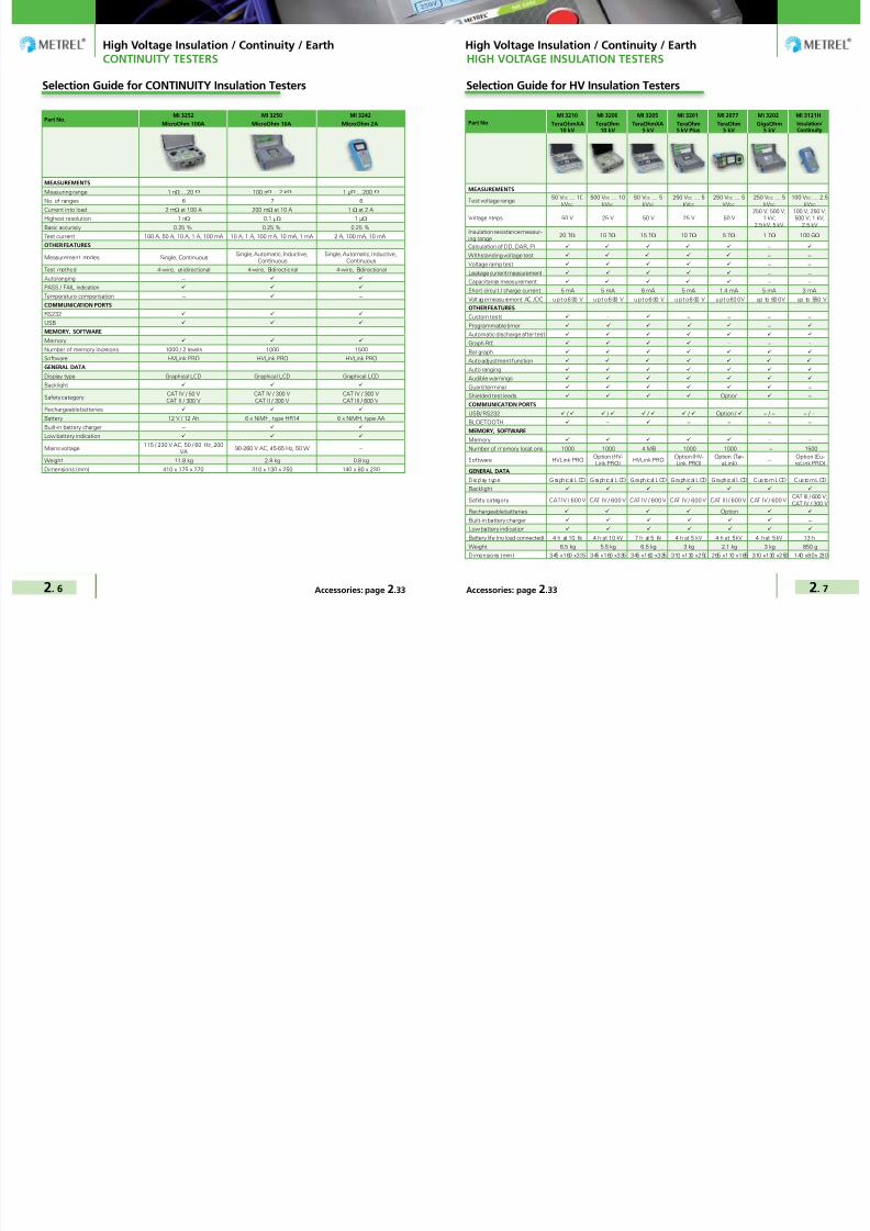
7/25/2019 METREL General Catalog Engl 2015
http://slidepdf.com/reader/full/metrel-general-catalog-engl-2015 41/121
High Voltage Insulation / Continuity / Earth High Voltage Insulation / Continuity / Earth
2. 6 2. 7Accessories: page 2.33 Accessories: page 2.33
Selection Guide for HV Insulation TestersSelection Guide for CONTINUITY Insulation Testers
Part No.MI 3210 MI 3200 MI 3205 MI 3201 MI 2077 MI 3202 MI 3121H
TeraOhmXA10 kV
TeraOhm10 kV
TeraOhmXA5 kV
TeraOhm5 kV Plus
TeraOhm5 kV
GigaOhm5 kV
Insulation/Continuity
MEASUREMENTS
Test voltage range50 VDC … 10
kVDC
500 VDC … 10kVDC
50 VDC … 5kVDC
250 VDC … 5kVDC
250 VDC … 5kVDC
250 VDC … 5kVDC
100 VDC … 2.5kVDC
Voltage steps 50 V 25 V 50 V 25 V 50 V250 V; 500 V;
1 kV;2.5 kV; 5 kV
100 V; 250 V;500 V; 1 kV;
2.5 kVInsulation resistance measur-ing range
20 TΩ 10 TΩ 15 TΩ 10 TΩ 5 TΩ 1 TΩ 100 GΩ
Calculation of DD, DAR, PI −
Withstanding voltage test − −
Voltage ramp test − −
Leakage current measurement − −
Capacitance measurement − −
Short circuit / charge current 5 mA 5 mA 6 mA 5 mA 1.4 mA 5 mA 3 mA
Volt ag e measu rement AC / DC u p t o 6 00 V u p t o 6 00 V u p t o 6 00 V u p t o 6 00 V u p t o 60 0 V up to 60 0 V up to 550 V
OTHER FEATURES
Custom tests − − − − −
Programmable timer −
Automatic discharge after test
Graph R(t) − − −
Bar graph
Auto adjustment function
Auto ranging
Audible warnings
Guard terminal −
Shielded test leads Option −
COMMUNICATION PORTS
USB/ RS232 / / / / Option / − / − − / −
BLOETOOTH − − − − −MEMORY, SOFTWARE
Memory − −
Number of memory locations 1000 1000 4 MB 1000 1000 − 1500
Software HVLink PROOption (HV-Link PRO)
HVLink PROOption (HV-Link PRO)
Option (Ter-aLink)
−Option (Eu-roLink PRO)
GENERAL DATA
Dis pl ay type Gra ph ic al LCD Gra ph ic al LCD Gra ph ic al LCD Gra ph ic al LCD Gra ph ic al LCD Cus tom LCD Cus tom LCD
Backlight
Safety category CAT IV / 600 V CAT IV / 600 V CAT IV / 600 V CAT IV / 600 V CAT III / 600 V CAT IV / 600 VCAT III / 600 V;CAT IV / 300 V
Rechargeable batteries Option
Built-in battery charger −
Low battery indication
Battery life (no load connected) 4 h at 10 kV 4 h at 10 kV 7 h at 5 kV 4 h at 5 kV 4 h at 5 kV 4 h at 5 kV 13 h
Weight 6.5 kg 5.5 kg 6.5 kg 3 kg 2.1 kg 3 kg 850 g
Dimensions (mm) 345 x 160 x 335 345 x 160 x 335 345 x 160 x 335 310 x 130 x 250 265 x 110 x 185 310 x 130 x 250 140 x 80 x 230
Part No.MI 3252 MI 3250 MI 3242
MicroOhm 100A MicroOhm 10A MicroOhm 2A
MEASUREMENTS
Measuring range 1 nΩ ... 20 Ω 100 nΩ ... 2 kΩ 1 µΩ ... 200 Ω
No. of ranges 6 7 6
Current into load 2 mΩ at 100 A 200 mΩ at 10 A 1 Ω at 2 AHighest resolution 1 nΩ 0.1 µΩ 1 µΩ
Basic accuracy 0.25 % 0.25 % 0.25 %
Test current 100 A, 50 A, 10 A, 1 A, 100 mA 10 A, 1 A, 100 mA, 10 mA, 1 mA 2 A, 100 mA, 10 mA
OTHER FEATURES
Measurement modes Single, ContinuousSingle, Automatic, Inductive,
ContinuousSingle, Automatic, Inductive,
Continuous
Test method 4-wire, unidirectional 4-wire, Bidirectional 4-wire, Bidirectional
Autoranging −
PASS / FAIL indication
Temperature compensation − −
COMMUNICATION PORTS
RS232
USB
MEMORY, SOFTWARE
Memory
Number of memory locations 1000 / 2 levels 1000 1500
Software HVLink PRO HVLink PRO HVLink PRO
GENERAL DATA
Display type Graphical LCD Graphical LCD Graphical LCD
Backlight
Safety categoryCAT IV / 50 VCAT II / 300 V
CAT IV / 300 VCAT II / 300 V
CAT IV / 300 VCAT III / 600 V
Rechargeable batteries
Battery 12 V / 12 Ah 6 x NiMH, type HR14 6 x NiMH, type AA
Built-in battery charger −
Low battery indication
Mains voltage115 / 230 V AC, 50 / 60 Hz, 200
VA90-260 V AC, 45-65 Hz, 50 W −
Weight 11.8 kg 2.8 kg 0.8 kg
Dimensions (mm) 410 x 175 x 370 310 x 130 x 250 140 x 80 x 230
CONTINUITY TESTERS HIGH VOLTAGE INSULATION TESTERS
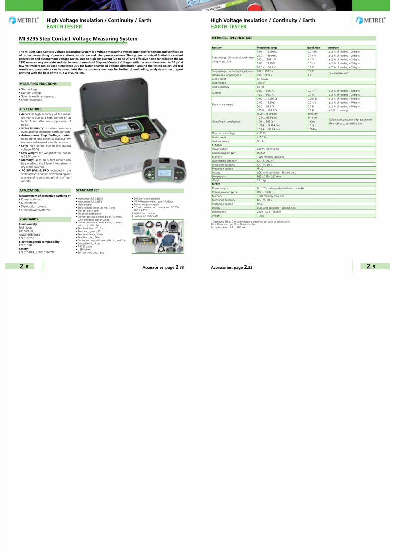
7/25/2019 METREL General Catalog Engl 2015
http://slidepdf.com/reader/full/metrel-general-catalog-engl-2015 42/121
High Voltage Insulation / Continuity / Earth High Voltage Insulation / Continuity / Earth
2. 8 2. 9Accessories: page 2.33 Accessories: page 2.33
EARTH TESTER
MEASURING FUNCTIONS:
• Step voltage;• Contact voltage;
• Specific earth resistance;• Earth resistance.
KEY FEATURES:
• Accurate: high accuracy of the meas-urements due to a high current of upto 50 A and effective suppression ofnoise.
• Noise immunity: excellent immunityeven against changing earth currents.
• Autonomous Step Voltage meter: no need for long potential leads; a fewmeters can be used simultaneously.
• Safe: high safety due to low outputvoltage (55 V).
• Low weight: the weight of the Stationis 29.5 kg only.
• Memory: up to 1000 test results canbe saved into the 3-level internal mem-ory of the system.
• PC SW HVLink PRO included in thestandard set enables downloading andanalysis of results and printing of testreports.
APPLICATION:Measurement of protective earthing of:• Power stations;• Substations;• Distribution towers;• Other power systems.
STANDARDS:
Functionality:RAT 2008;HD 673 N4;ANSI/IEEE Std 81;EN 61557-5Electromagnetic compatibility:EN 61326Safety:EN 61010-1; EN 61010-031
The MI 3295 Step Contact Voltage Measuring System is a voltage measuring system intended for testing and verificationof protective earthing of power stations, substation and other power systems. The system consists of Station for currentgeneration and autonomous voltage Meter. Due to high test current (up to 55 A) and effective noise cancellation the MI3295 ensures very accurate and stable measurements of Step and Contact Voltages with the resolution down to 10 µV. Afew voltmeters can be used simultaneously for faster analysis of voltage distribution around the tested object. All testresults and parameters can be saved into the instrument’s memory for further downloading, analysis and test reportprinting with the help of the PC SW HVLink PRO.
• Instrument MI 3295M• Instrument MI 3295S• Mains cable• Step voltage probe (25 kg), 2 pcs• Current earth spike• Potential earth spike• Current test lead, 50 m, black, 10 mm2,
with crocodile clip, on wheel• Current test lead, 10 m, black, 10 mm2,
with crocodile clip• Test lead, black, 2 x 3 m• Test lead, green, 10 m• Test lead, black, 1.5 m• Test lead, red, 50 m• Connection lead with crocodile clip, re d, 1 m• Crocodile clip, 4 pcs• RS232 cable• USB cable• Soft carrying bag, 2 pcs
STANDARD SET:
• Soft carrying neck belt• NiMH battery cells, type AA, 6 pcs• Power supply adapter• CD with instruction manual and PC SW
HVLink PRO• Instruction manual• Calibration certificate
MI 3295 Step Contact Voltage Measuring System
EARTH TESTER
TECHNICAL SPECIFICATION:
Function Measuring range Resolution Accuracy
Step voltage, Contact voltage (meas-
uring range Um)
0.01 … 19.99 mV
20.0 … 199.9 mV
200 … 1999 mV
2.00 … 19.99 V
20.0 V … 59.9 V
0.01 mV
0.1 mV
1 mV
0.01 V
0.1 V
±(2 % of reading + 2 digits)
±(2 % of reading + 2 digits)
±(2 % of reading + 2 digits)
±(2 % of reading + 2 digits)
±(2 % of reading + 2 digits)
Step voltage, Contact voltage (calcu-
lated measuring range U)
0.0 … 199.9 V
200 … 999 V
0.1 V
1 Vcalculated value*
Test current 55 A max
Test voltage < 55 V
Test frequency 55 Hz
Current0.00 … 9.99 A
10.0 … 99.9 A
0.01 A
0.1 A
±(3 % of reading + 5 digits)
±(3 % of reading + 3 digits)
Resistance to earth
0.001 … 1.999 Ω
2.00 … 19.99 Ω
20.0 … 99.9 Ω
100.0 … 199.9 Ω
0.001 Ω
0.01 Ω
0.1 Ω
0.1 Ω
±(2 % of reading + 5 digits)
±(2 % of reading + 5 digits)
±(2 % of reading + 5 digits)
±5 % of reading)
Specific earth resistance
0.00 … 9.99 Ωm
10.0 … 99.9 Ωm
100 … 999 Ωm
1.00 k … 9.99 kΩm
10.0 k … 99.9 kΩm
0.01 Ωm
0.1 Ωm
1 Ωm
10 Ωm
100 Ωm
Calculated value, consider accuracy of
Resistance to earth function.
Open circuit voltage < 50 VAC
Test current < 7.5 A
Test frequency 55 Hz
STATION
Power supply 230 V / 50 or 60 Hz
Communication port RS232
Memory 1000 memory locations
Overvoltage category CAT II / 300 V
Measuring category CAT IV / 50 V
Protection degree IP 30
Display LCD with backlight (128 x 64 dots)
Dimensions 563 x 275 x 257 mm
Weight 29.5 kg
METER
Power supply 6 x 1.2 V rechargeable batteries, type AA
Communication ports USB, RS232Memory 1500 memory locations
Measuring category CAT IV / 50 V
Protection degree IP 40
Display LCD with backlight (128 x 64 dots)
Dimensions 230 x 103 x 115 mm
Weight 1.3 kg
*Displayed Step / Contact voltage is obtained on base of calculation:US = Umeas·Ifault / Igen; UC = Umeas·Ifault / Igen;Ifault (selectable): 1 A ... 200 kA

7/25/2019 METREL General Catalog Engl 2015
http://slidepdf.com/reader/full/metrel-general-catalog-engl-2015 43/121
High Voltage Insulation / Continuity / Earth High Voltage Insulation / Continuity / Earth
2. 10 2. 11Accessories: page 2.33 Accessories: page 2.33
CONTINUITY TESTERS
MEASURING FUNCTIONS:
• Resistance measurement with adjust-able test current (100 mA … 100 A);
• Voltage drop measurement.
KEY FEATURES:
• Accurate: 1 nΩ best resolution with0.25% accuracy.
• Bar graph: on screen resistance bargraph.
• Battery powered: the instrument ena-bles measurements with 100 A for upto 10 minutes when powered from in-ternal battery only.
• Safe: sustain external voltages in caseof wrong connection, protection level(CAT IV / 50 V); automatically detectscontinuity in current circuit.
• Single and continuous measuringmodes.
• Custom limits: the limits can be set forPASS or FAIL evaluation of test result.
• Portable: rugged carrying case witha handle and lightweight design (lessthan 12 kg) enable easy moving the in-strument between sites.
• High protection degree: IP 64.• Memory: built-in memory enables
storage of up to 1000 test results.• Downloadable: downloads test re-
sults via RS232 or USB cable directlyto the PC with the help of the HVLinkPRO software.
APPLICATION:
Measurement the resistance of:• High, middle and low voltage circuit
breakers;• High, middle and low voltage discon-
necting switches;• High current busbar joints;• Cable splices;• Welding joints.
The MI 3252 MicroOhm 100A is portable low resistance ohmmeter used to measure low contact resistances of circuitbreakers, switches and busbars joints using test current from 100 mA to 100 A. Used 4-lead Kelvin testing method ensuresvery high accuracy of results (0.25%) due to elimination of test leads resistance. The instrument can be powered fromboth mains supply and internal batt ery. PC SW HVLink PRO supplied as a st andard accessory enables downloading, analy-sis and export of test results and printing of test reports.
STANDARDS:
Functionality:IEC 62271-100;IEC 62271-1;ANSI C37.09;ASTM B 539;NMEA AB 4-1996;El Real Decreto 223/2008Electromagnetic compatibility:IEC 61326-1 Class BSafety:EN 61010-1
MI 3252 MicroOhm 100A
CONTINUITY TESTERS
TECHNICAL SPECIFICATION:
Function Measuring range Resolution Accuracy Current
Resistance
10.000 … 199.999 µΩ
0.20000 … 1.99999 mΩ
2.0000 ... 19.9999 mΩ
20.000 … 199.999 mΩ
0.20000 … 1.99999 Ω
2.0000 … 19.9999 Ω
1 nΩ
10 nΩ
100 nΩ
1 µΩ
10 µΩ
100 µΩ
±0.25 % of reading
±0.25 % of reading
±0.25 % of reading
±0.25 % of reading
±0.25 % of reading
±0.25 % of reading
100 A
100 A / 50 A
50 A / 10 A
1 / 10 A
1 A / 100 mA
100 mA
Function Resistance range Voltage range Resolution Accuracy Current
Voltage
200 µΩ
2 mΩ
20 mΩ
200 mΩ
2 Ω
20 Ω
1.000 mV … 20.000 mV
20.00 mV … 200.00 mV
10.00 mV … 100.00 mV
100.0 mV … 1.0000 V
20.0 mV … 200.0 mV200.0 mV … 2.0000 V
20.0 mV … 200.0 mV
200.0 mV … 2.0000 V
20.0 mV … 200.0 mV
200.0 mV … 2.0000 V
1 µV
10 µV
10 µV
0.1 mV
0.1 mV0.1 mV
0.1 mV
0.1 mV
0.1 mV
0.1 mV
±0.25 % of reading
±0.25 % of reading
±0.25 % of reading
±0.25 % of reading
±0.25 % of reading±0.25 % of reading
±0.25 % of reading
±0.25 % of reading
±0.25 % of reading
±0.25 % of reading
100 A
100 A
50 A
50 A
10 A1 A
10 A
1 A
100 mA
100 mA
Power supply 230 / 115 VAC
Battery 12 VDC / 12 Ah
Overvoltage category CAT IV / 50 V
Display 320 x 240 LCD with backlight
Communica ti ons RS 232 and USB
Memory 512 kB (1000 test results)
Dimensions 410 x 175 x 370 mm
Weight 11.8 kg
• Instrument MicroOhm 100A• Current test lead with crocodile clip, 5 m,
25 mm2, 2 pcs• Potential test lead, 5 m, 2 pcs (red, black)• Test probe, 2 pcs (red, black)• Crocodile clip, 2 pcs (red, black)• Mains cable
• RS232 cable• USB cable
STANDARD SET:
• Bag for accessories• PC SW HVLink PRO• Instruction manual• Calibration certificate

7/25/2019 METREL General Catalog Engl 2015
http://slidepdf.com/reader/full/metrel-general-catalog-engl-2015 44/121
High Voltage Insulation / Continuity / Earth High Voltage Insulation / Continuity / Earth
2. 12 2. 13Accessories: page 2.33 Accessories: page 2.33
MEASURING FUNCTIONS:
• Bidirectional resistance measurement
from 0,1 µΩ up to 2000 Ω with testcurrent up to 10 A;
• Temperature compensation (with op-tional temperature probe).
KEY FEATURES:
• Accurate: 0.1 nΩ best resolution with0.25% accuracy.
• Bar graph: on screen resistance bargraph.
• Battery powered: more than 1000measurements with 10 A test currentcan be performed when powered byinternal battery only.
• Safe: High overvoltage category CATIV / 300 V.
• Four measuring modes: Automatic,single, continuous and inductive
• Automatic thermal EMF elimination: with automatic bidirectional measure-ment .
• Temperature compensation: meas-ured resistance can be adjusted ac-cording to ambient temperature, whichcan be entered manually or measuredby external probe
• Custom limits: limits can be set forPASS/FAIL evaluation of test results.
• Portable: lightweight 3 kg design withcarry handle and shoulder strap.
• Memory: built-in memory enablesstorage of up to 1000 test results.
• Downloadable: stored test resultscan be via RS232 or USB interfacetransferred to the PC with installedHVLink PRO software, which enablesdownloading, review, analyses andprinting of the test results.
The MI 3250 MicroOhm 2A is portable low resistance ohmmeter for measuring low resistances of breakers and switches,busbars, cable joints, small to medium sized transformer and motor windings for industrial application, etc., with testcurrent up to 10 A. The used 4-lead Kelvin testing method together with automatic bidirectional procedure ensure veryhigh accuracy of test results (0,25%). The instrument can be powered by mains or internal rechargeable batteries. Testresults can be stored on the instrument and with PC software HVLink PRO that is supplied as a part of standard set enablestransfer of measured results to PC where they can be analyzed or printed.
MI 3250 MicroOhm 10A
APPLICATION:
Measurement the resistance of:• Bus bar joints• Motor and transformer windings• Cables• Fuses• Aircraft frame bonds• Rail and pipe bonds• Lightning conductor bonding
CONTINUITY TESTERS
STANDARDS:
Electromagnetic compatibility:
IEC 61326-1
Safety:
EN 61010-1;
EN 61010-031
TECHNICAL SPECIFICATION:
Function Measuring range Resolution Accuracy Current
Resistance
1.9999 mΩ
19.999 mΩ
199.99 mΩ
1.9999 Ω
19.999 Ω
19.999 Ω
199.99 Ω
199.99 Ω
1.9999 kΩ
0.1 µΩ
1 µΩ
10 µΩ
100 µΩ
1 mΩ
10 mΩ
10 mΩ
100 mΩ
1 Ω
±(0.25 % of reading + 0.01 % FS)±(0.25 % of reading + 0.01 % FS)±(0.25 % of reading + 0.01 % FS)±(0.25 % of reading + 0.01 % FS)±(0.25 % of reading + 0.01 % FS)±(1 % of reading + 0.1 % FS)±(0.25 % of reading + 0.01 % FS)±(1 % of reading + 0.25 % FS)±(1 % of reading + 0.25 % FS)
10 A10 A/1 A10 A/1 A/100 mA1 A/100 mA/10 mA100 mA/10 mA1 mA10 mA1 mA1 mA
Power supply (mains voltage) 90 ... 260 VAC / 60 VA
Power supply (batteries) 6 x 1.2 V NiMH 3500 mAh batteries, type C
Operation > 1000 single measurements
Ov er vol tag e cat eg or y C AT IV / 3 00 VProtection class Double insulation
Display 320 x 240 LCD with backlight
Communication RS232 and USB
Memory 1000 memory locations
Dimensions 310 x 130 x 250 mm
Weight 2.8 kg
CONTINUITY TESTERS
KEY FEATURES
Test lead connection terminal with fourbanana safety sockets.
Fast and simple adjustment of the testparameters
Large analogue / digital LCD with backlight
• Instrument MI 3250• Test cable, 2 m, with Kelvin Clip, 2 pcs• Test cable, 2.5 m, 4 pcs (2 x black, 2 x red)• Crocodile clip, 4 pcs (2 x black, 2 x red)• Test probe, 2 pcs (red, black)• Mains cable• USB cable and RS232 cable• NiMH rechargeable batteries, type C, 6 pcs
STANDARD SET:
• PC SW HVLink PRO• Bag for accessories• Instruction manual• Calibration certificate

7/25/2019 METREL General Catalog Engl 2015
http://slidepdf.com/reader/full/metrel-general-catalog-engl-2015 45/121
High Voltage Insulation / Continuity / Earth High Voltage Insulation / Continuity / Earth
2. 14 2. 15Accessories: page 2.33 Accessories: page 2.33
MEASURING FUNCTIONS:
• Bidirectional resistance measurement
from 1 µΩ up to 199,9 Ω with test cur-
rent up to 2 A.
KEY FEATURES:
• Four measuring modes: Automatic,
single, continuous and inductive
• Automatic thermal EMF elimina-
tion: with automatic bidirectional
measurement.
• Accurate: 1 µΩ best resolution with
0.25% accuracy.
• Noise rejection: 50 Hz / 60 Hz ripple
detection and rejection.
• Battery powered: more than 800
measurements of 500 mΩ load ∞ 2
A test current & 15 s measurement
duration.
• Safe: High overvoltage protection
(CAT III / 600 V) allows measurement
in substations and other points with
low line resistance. Internal protec-
tion circuit protects user and instru-
ment from inadvertent connection tolines.
• Custom limits: Pre-programmed
limits with PASS/FAIL evaluation of
measurement result and bright REEN/
RED indicators providing visual evalu-
ation of the results.
• Portable: Lightweight portable de-
sign.
• Memory: Up to 1500 test results with
timestamp can be stored in internal
memory.
• Downloadable: PC SW HVLink PRO
enables downloading, review, analy-
ses and printing of test results.
MI 3242 MicroOhm 2A is a portable low resistance ohmmeter used to measure low resistances of switches, relays, con-nectors, bus bars, power distribution cable joints, motor & generator winding, power transformers, power inductors, railtrack joints, wire and cable resistance, welding joints for industrial application, etc., with test current up to 2A
MI 3242 MicroOhm 2A
APPLICATION:
Measurement the resistance of:In inductive mode:• Motor & generator winding• Power transformer• Power inductors• Wire & cable resistance
In resistance mode:• Ralays• Switches• Connectors
TECHNICAL SPECIFICATION:
KEY FEATURES
Test lead connection terminal and USB andRS232 communication ports.
Large analogue / digital LCD with backlight Fast and simple adjustment of the testparameters
• Instrument MI 3242 MicroOhm 2A• Test cable, 2 m, with Kelvin Clip• Test cable 4 wire, 2.5 m• Crocodile clip, 4 pcs (2x black, 2x red)• Test probe, 2 pcs (black)• Power supply adapter• 1.2 V NiMH rechargeable battery, 6pcs• RS232 serial cable
STANDARD SET:
• USB cable• Soft carrying bag• PC SW HVLink PRO• Instruction manual• Calibration certificate
Function Measuring range Resolution Accuracy Current
Resistance
9.999 mΩ 1 µΩ
±(0.25 % of reading + 2 digits)
2 A99.99 mΩ 10 µΩ
999.9 mΩ 100 µΩ
99.99 mΩ 10 µΩ
100 mA999.9 mΩ 100 µΩ
9.999 Ω 1 mΩ
19.99 Ω 10 mΩ
999.9 mΩ 100 µΩ
10 mA9.999 Ω 1 mΩ
99.99 Ω 10 mΩ
199.9 Ω 100 mΩ
Voltage 0 ... 49.9 0.1 V ±(2 % of reading + 2 digits)50 ... 550 1 V
Frequency10.0 ... 99.9 0.1 Hz
±(0.2 % of reading + 1 digit)100 ... 500 1 Hz
Power supply (batteries) 9 VDC (6 x 1.5 V battery or accu, size AA)
Operation > 800 single measurements
Overv ol ta ge ca tegory CAT II I / 600 V; CAT IV / 300 V
Protection class Double insulation
Display 128 x 64 dots matrix display with backlight
Communication RS232 and USB
Memory 1500 memory locations
Dimensions 140 x 80 x 230 mm
Weight 0.8 kg
• Busbars• Power distributor
STANDARDS:
Electromagnetic compatibility:
EN 61326 Class A
Safety:
EN 61010-1EN 61010-031EN 61010-2-30

7/25/2019 METREL General Catalog Engl 2015
http://slidepdf.com/reader/full/metrel-general-catalog-engl-2015 46/121
High Voltage Insulation / Continuity / Earth High Voltage Insulation / Continuity / Earth
2. 16 2. 17Accessories: page 2.33 Accessories: page 2.33
MEASURING FUNCTIONS:
• Insulation Measurement;• Diagnostic Test (PI, DAR, DD) ;
• Step Voltage Test;• Withstanding Voltage Test (DC) up to
10 kV;• Voltage and frequency measurement
up to 550 V TRMS.
KEY FEATURES:
• Insulation resistance up to 20 TΩ;
• Adjustable test voltage (50 V...10 kV)50 V and 100 V step;
• Programmable timer;
• Capacitance measurement;
• Charging rate for capacitive load < 3 s / µF at 10 kV;
• Automatic discharge of test object af-ter completion of measurement;
• Guard terminal
• High voltage breakdown detection;
• Custom defined tests
• Auto adjustment function
• Measurement results in numericaland graphical form;
• PC software HVLink PRO for down-loading and analyzing of the test re-sults and test report printing;
• Isolated RS232 and USB communica-tion ports, BT interface;
• High quality accessories includingshielded test leads in standard set;
• High EM interferences protection:Input AC current noise rejection (1mA∞600 V) and additional averagingof the result (5, 10, 30, 60);
• CAT IV / 600 V;
• Mains and rechargeable battery powersupply.
MI 3210 TeraOhm XA 10 kV is a portable, battery or mains powered test instrument with excellent IP protection (IP65),intended for diagnosing of Insulation Resistance by using high DC test voltages of up to 10 kV. Because of its robustness(CAT IV protection) and high immunity to radiated RF fields it is best suited for industrial environment.
APPLICATION:
• Power transformers;
• Measuring transducers in distribution
networks;
• Testing insulation resistance of rotat-
ing machinery and cables;
• Production line periodic testing and
maintenance;
• Troubleshooting and analysis of all
kinds of insulation problems;
• High voltage generators;
• Surge arrestors.
STANDARDS:
Electromagnetic compatibility:
EN 61326 class A
Safety:
EN 61010-1 (instrument)
EN 61010-2-030
EN 61010-2-033
EN 61010-031(accessories)
MI 3210 TeraOhmXA 10 kV TECHNICAL SPECIFICATION:
Function Measuring range Resolution Accuracy
Insulation resistance
0.01 MΩ … 9.99 MΩ
10.0 MΩ … 99.9 MΩ
100 MΩ … 999 MΩ
1.00 GΩ … 9.99 GΩ
10.0 GΩ … 99.9 GΩ
100 GΩ … 999 GΩ
1.0 TΩ … 9.9 TΩ
10 TΩ … 20 TΩ
10 kΩ
100 kΩ
1 MΩ
10 MΩ
100 MΩ
1 GΩ
100 GΩ
1 TΩ
±(5% of reading + 3 digits)±(5% of reading + 3 digits)±(5% of reading + 3 digits)±(5% of reading + 3 digits)±(5% of reading + 3 digits)±(5% of reading + 3 digits)±(5% of reading + 3 digits)±(15% of reading + 3 digits)
Test voltage0 V … 999 V1.00 kV… 9.99 kV10.0 kV … 14.0 kV
1 V10 V100 kV
±(5% of reading + 3 digits)
Insulation leakage current
1.00 mA … 5.00 mA100 µA … 999 µA
10.0 µA … 99.9 µA1.00 µA … 9.99 µA100 nA ... 999 nA10.0 nA .. 99.9 nA0.00 nA … 9.99 nA
10 µA1 µA
100 nA10 nA1 nA100 pA10 pA
±(5% of reading + 3 digits)
±(10% of reading + 0.15 nA)
Dielectric absorption ratio (DAR)0.01 … 9.9910.0 … 100.0
0.010.1
±(5% of reading + 2 digits)
Polarization index (PI)0.01 … 9.9910.0 … 100.0
0.010.1
±(5% of reading + 2 digits)
Dielectric discharge (DD)0.01 … 9.9910.0 … 100.0
0.010.1
±(5% of reading + 2 digits)
Voltage AC/DC5.0 V … 99.9 V100 V … 550 V
0.1 V1 V
±(2% of reading + 2 digits)
Frequency 10 Hz … 500 Hz 0.1 Hz ±(0.2% of reading + 1 digits)
Capacitance20.0 nF … 999 nF1.00 µF … 9.99 µF10.0 µF … 50.0 µF
1 nF10 nF100 nF
±(5% of reading + 2 digits)
Power supply 12 V DC (3.4 Ah Lead – Acid)
Display 320 x 240 dots matrix display with backlight
Overvoltage category CAT IV / 600 V
Protection class Double insulation
COM port RS232, USB and Bluetooth
Dimensions 345 x 160 x 335 mm
Weight 6.5 kg
• Instrument MI 3210 TeraOhmXA 10 kV• 10 kV shielded test lead with probe, 2 m• 10 kV shielded test lead, 2 m, 2 pcs (black, red)• 10 kV crocodile clip, 2 pcs (black, red)• Guard test lead, green, 2 m• Crocodile clip, green• Mains cable• PC SW HVLink PRO with USB and RS 232
cable
STANDARD SET:
• Handbook “Guide to modern insulationtesting” on CD
• Instruction manual on CD• Calibration certificate

7/25/2019 METREL General Catalog Engl 2015
http://slidepdf.com/reader/full/metrel-general-catalog-engl-2015 47/121
High Voltage Insulation / Continuity / Earth High Voltage Insulation / Continuity / Earth
2. 18 2. 19Accessories: page 2.33 Accessories: page 2.33
MEASURING FUNCTIONS:
• Insulation resistance measurement;• Step voltage insulation resistance test-
ing;• Withstanding voltage testing;• Diagnostic test (PI, DD, DAR);• R(t) graph plotting;• Capacitance measurement;• Voltage measurement;• Frequency measurement.
KEY FEATURES:
• Measuring range up to 10 TΩ. • Wide range of DC test voltages: from
500 V up to 10000 V in steps of 25 V.• Withstanding voltage: testing of in-
sulation with programmable ramp testvoltage from 500 V up to 10 kV andprogrammable threshold current.
• Step voltage: insulation resistancemeasurement with five discrete pro-portionately set test voltages and pro-grammable timer per step.
• Automated testing: PI, DD, DAR cal-culations with automated resistanceranging. All data is displayed duringone single measurement.
• Guard test terminal: for elimination ofpotential surface leakage currents.
• Fault finding: fully programmable stepvoltage and withstanding voltage testfunctions assist in diagnosing faults ininsulation.
• Graph R(t): real time resistance againsttime graph plotting facility to graphical-ly illustrate the response of a materialto an applied test voltage.
• Built-in timer: programmable timerfrom 1 s up to 100 min.
• Automatic discharge of tested objectafter test.
• Fast testing: 5 mA current source forquick charging of capacitive load.
• Accurate: selectable noise rejection fil-ters and shielded test leads included ina standard set ensure accurate meas-urement.
The new insulation tester MI 3202 TeraOhm 10 kV is a portable instrument intended to measure insulation resistance byusing high DC test voltages up to 10 kV. TeraOhm 10 kV enables insulation resistance measurements up to 10 T Ω, stepvoltage test, withstanding voltage test, PI, DD and DAR calculation and capacitance measurement. The large LCD screenenables real-time graph R(t) to be displayed. Results can be stored and downloaded to a computer via USB or RS232 con-nection with the help of the optional HVLink PRO softw are. The high quality instrument, shielded test leads and qualityaccessories included in the standard set enable to perform insulation testing quickly and effectively.
• Safe: high CAT IV / 600 V voltage pro-tection.
• Built-in charger & rechargeable bat-teries: instrument has a built-in charg-er and comes complete with a set ofrechargeable NiMH batteries.
• Portable: lightweight 5.5 kg designwith carry handle.
APPLICATION:
• Testing insulation resistance of rotat-ing machinery, cables, transformers,HV generators, surge arresters;
• Production line periodic testing andmaintenance;
• Troubleshooting and analysis of allkinds of insulation problems;
• Effective measurements in high noiseenvironments such as high voltagesubstations and switchyards;
• Diagnostic testing.
STANDARDS:
Functionality:IEC/EN 61557-2Electromagnetic compatibility:EN 61326 class BSafety:EN 61010-1;EN 61010-031
HIGH VOLTAGE INSULATION TESTERS
MI 3200 TeraOhm 10 kV TECHNICAL SPECIFICATION:
Function Measuring range Resolution Accuracy
Insulation resistance
5 kΩ … 999 kΩ
1.00 MΩ … 9.99 MΩ
10.0 MΩ … 99.9 MΩ
100 MΩ … 999 MΩ
1.00 GΩ … 9.99 GΩ
10.0 GΩ … 99.9 GΩ
100 GΩ … 999 GΩ
1.00 TΩ … 10.00 TΩ
1 kΩ
10 kΩ
100 kΩ
1 MΩ
10 MΩ
100 MΩ
1 GΩ
10 GΩ
±(5 % of reading + 3 digits)
±(5 % of reading + 3 digits)
±(5 % of reading + 3 digits)
±(5 % of reading + 3 digits)
±(5 % of reading + 3 digits)
±(5 % of reading + 3 digits)
±(5 % of reading + 3 digits)
±(15 % of reading + 3 digits)
Test voltage0 V … 9999 V
≥ 10 kV
1 V
0.1 kV
±(3 % of reading + 3 V)
±3 % of reading
Insulation leakage current
0.00 nA … 9.99 nA
10.0 nA … 99.9 nA100 nA … 999 nA
1.00 µA … 9.99 µA
10.0 µA … 99.9 µA
100 µA … 999 µA
1.00 mA … 5.50 mA
0.01 nA
0.1 nA1 nA
10 nA
100 nA
1 µA
10 µA
±(5% of reading + 0.05 nA)
Dielectric absorption ratio (DAR)0.01 … 9.99
10.0 … 100.0
0.01
0.1
±(5 % of reading + 2 digits)
±5 % of reading
Polarization index (PI)0.01 … 9.99
10.0 … 100.0
0.01
0.1
±(5 % of reading + 2 digits)
±5 % of reading
Dielectric discharge (DD)0.01 … 9.99
10.0 … 100.0
0.01
0.1
±(5 % of reading + 2 digits)
±5 % of reading
Voltage AC/DC 0 V … 600 V 1 V ±(3 % of reading + 4 V)
Frequency 45.0 Hz … 65.0 Hz 0.1 Hz ±0.2 Hz
Capacitance
0.0 nF … 99.9 nF
100 nF … 999 nF
1.00 µF … 50.00 µF
0.1 nF
1 nF
10 nF
±(5 % of reading + 2 digits)
Power supply 6 × 1.2 V NiMH rechargeable batteries, type D
Display Matrix LCD with backlight, 160 x 116 dots
Overvoltage category CAT IV / 600 V
Protection class Double insulation
COM port RS232 and USB
Dimensions 345 x 160 x 335 mm
Weight 5.5 kg
• Instrument TeraOhm 10 kV• Mains cable• 10 kV shielded test lead with tip, 2 m• 10 kV shielded test lead black, 2 m• 10 kV shielded test lead red, 2 m• 10 kV crocodile clip, 2 pcs (black, red)• Guard lead, green, 2 m• Crocodile clip, green• 6 x 1.2 V NiMH rechargeable batteries, type D
STANDARD SET:
• Instruction manual• Handbook on CD• Calibration certificate
HIGH VOLTAGE INSULATION TESTERS

7/25/2019 METREL General Catalog Engl 2015
http://slidepdf.com/reader/full/metrel-general-catalog-engl-2015 48/121
High Voltage Insulation / Continuity / Earth High Voltage Insulation / Continuity / Earth
2. 20 2. 21Accessories: page 2.33 Accessories: page 2.33
MEASURING FUNCTIONS:
• Insulation Measurement;• Diagnostic Test (PI, DAR, DD);
• Step Voltage Test;• Withstanding Voltage Test (DC) up to 5 kV;• Voltage and frequency measurement
up to 550 V TRMS.
KEY FEATURES:
• Insulation resistance up to 15 TΩ;
• Adjustable test voltage (50 V...5 kV) 50V and 100 V step;
• Programmable timer;
• Capacitance measurement;
• Charging rate for capacitive load < 1,5s / µF at 5 kV;
• Automatic discharge of test object af-ter completion of measurement;
• Guard terminal
• High voltage breakdown detection;
• Custom defined tests
• Auto adjustment function
• Measurement results in numericaland graphical form;
• PC software HVLink PRO for down-loading and analyzing of the test re-sults and test report printing;
• Isolated RS232 and USB communica-tion ports, BT interface;
• High quality accessories includingshielded test leads in standard set;
• High EM interferences protection:Input AC current noise rejection (1mA∞300 V) and additional averagingof the result (5, 10, 30, 60);
• CAT IV / 600 V;
• Mains and rechargeable battery (Li-ion)power supply.
MI 3205 TeraOhm XA 5kV is a portable battery (Li-ion) or mains powered test instru- ment with excellent IP protection(IP65 case closed and IP54 case open), intended for diagnosing of Insulation Resistance by using high test voltages of upto 5 kV. It is designed and produced with the extensive knowledge and experience acquired through many years of work-ing in this field.
APPLICATION:
• Power transformers;
• Measuring transducers in distribution
networks;
• Testing insulation resistance of rotat-
ing machinery and cables;
• Production line periodic testing and
maintenance;
• Troubleshooting and analysis of all
kinds of insulation problems;
• High voltage generators;
• Surge arrestors and varistors.
STANDARDS:
Electromagnetic compatibility:
EN 61326 class A
Safety:
EN 61010-1 (instrument)
EN 61010-2-030
EN 61010-2-033
EN 61010-031(accessories)
MI 3205 TeraOhmXA 5 kV TECHNICAL SPECIFICATION:
Function Measuring range Resolution Accuracy
Insulation resistance
0.01 MΩ … 9.99 MΩ
10.0 MΩ … 99.9 MΩ
100 MΩ … 999 MΩ
1.00 GΩ … 9.99 GΩ
10.0 GΩ … 99.9 GΩ
100 GΩ … 999 GΩ
1.0 TΩ … 9.9 TΩ
10 TΩ … 15 TΩ
10 kΩ
100 kΩ
1 MΩ
10 MΩ
100 MΩ
1 GΩ
100 GΩ
1 TΩ
±(5% of reading + 3 digits)±(5% of reading + 3 digits)±(5% of reading + 3 digits)±(5% of reading + 3 digits)±(5% of reading + 3 digits)±(5% of reading + 3 digits)±(15% of reading + 3 digits)±(15% of reading + 3 digits)
Test voltage0 V … 999 V1.00 kV… 4.99 kV
1 V10 V
±(5% of reading + 3 digits)
Insulation leakage current
1.00 mA … 5.00 mA100 µA … 999 µA10.0 µA … 99.9 µA
1.00 µA … 9.99 µA100 nA ... 999 nA10.0 nA .. 99.9 nA0.00 nA … 9.99 nA
10 µA1 µA100 nA
10 nA1 nA100 pA10 pA
±(5% of reading + 3 digits)
±(10% of reading + 0.15 nA)
Dielectric absorption ratio (DAR)0.01 … 9.9910.0 … 100.0
0.010.1
±(5% of reading + 2 digits)
Polarization index (PI)0.01 … 9.9910.0 … 100.0
0.010.1
±(5% of reading + 2 digits)
Dielectric discharge (DD)0.01 … 9.9910.0 … 100.0
0.010.1
±(5% of reading + 2 digits)
Voltage AC/DC5.0 V … 99.9 V100 V … 550 V
0.1 V1 V
±(2% of reading + 2 digits)
Frequency 10 Hz … 500 Hz 0.1 Hz ±(0.2% of reading + 1 digits)
Capacitance20.0 nF … 999 nF1.00 µF … 9.99 µF10.0 µF … 50.0 µF
1 nF10 nF100 nF
±(5% of reading + 2 digits)
Power supply 90-260 VAC , 45-65 Hz 100 VA (CAT II / 300 V)
Protection degree close / open case IP 65 / IP 54
Display 320 x 240 dots matrix display with backlight
Overvoltage category CAT IV / 600 V
Protection class Reinforced insulation
COM port RS232, USB and Bluetooth
Dimensions 345 x 160 x 335 mm
Weight 6.5 kg
• Instrument MI 3205 TeraOhmXA 5 kV• 10 kV shielded test lead with probe, 2 m• 10 kV shielded test lead, 2 m, 2 pcs (black, red)• 10 kV crocodile clip, 2 pcs (black, red)• Guard test lead, green, 2 m• Crocodile clip, green• Mains cable• PC SW HVLink PRO with USB and RS 232
cable
STANDARD SET:
• Handbook “Guide to modern insulationtesting” on CD
• Instruction manual on CD• Calibration certificate

7/25/2019 METREL General Catalog Engl 2015
http://slidepdf.com/reader/full/metrel-general-catalog-engl-2015 49/121
High Voltage Insulation / Continuity / Earth High Voltage Insulation / Continuity / Earth
2. 22 2. 23Accessories: page 2.33 Accessories: page 2.33
MEASURING FUNCTIONS:
• Insulation resistance measurement;• Step voltage insulation resistance test-
ing;• Withstanding voltage testing;• Diagnostic test (PI, DD, DAR);• R(t) graph plotting;• Capacitance measurement;• Voltage measurement;• Frequency measurement.
KEY FEATURES:
• Measuring range up to 10 TΩ. • Wide range of DC test voltages: from
250 V up to 5000 V in steps of 25 V.• Withstanding voltage: testing of in-
sulation with programmable ramp testvoltage from 250 V up to 5 kV and pro-grammable threshold current.
• Step voltage: insulation resistancemeasurement with five discrete pro-portionately set test voltages and pro-grammable timer per step.
• Automated testing: PI, DD, DAR cal-culations with automated resistanceranging. All data is displayed duringone single measurement.
• Guard test terminal: for elimination ofpotential surface leakage currents.
• Fault finding: fully programmable stepvoltage and withstanding voltage testfunctions assist in diagnosing faults ininsulation.
• Graph R(t): real time resistance againsttime graph plotting facility to graphical-ly illustrate the response of a materialto an applied test voltage.
• Built-in timer: programmable timerfrom 1 s up to 10+0 min.
• Automatic discharge of tested objectafter test.
• Fast testing: 5 mA current source forquick charging of capacitive load.
• Accurate: selectable noise rejection fil-ters and shielded test leads included ina standard set ensure accurate meas-urement.
The new insulation tester MI 3201 TeraOhm 5 kV Plus is a portable instrument intended to measure insulation resistanceby using high DC test voltages up to 5 kV. TeraOhm 5 kV Plus enables insulation resistance measurements up to 10 TΩ, stepvoltage test, withstanding voltage test, PI, DD and DAR calculation and capacitance measurement. The large LCD screenenables real-time graph R(t) to be displayed. Results can be stored and downloaded to a computer via USB or RS232 con-nection with the help of the optional HVLink PRO softw are. The high quality instrument, shielded test leads and qualityaccessories included in the standard set enable to perform insulation testing quickly and effectively.
• Safe: high CAT IV / 600 V voltage pro-tection.
• Built-in charger & rechargeable bat-teries: instrument has a built-in charg-er and comes complete with a set ofrechargeable NiMH batteries.
• Portable: lightweight 3 kg design withcarry handle and shoulder strap.
APPLICATION:
• Testing insulation resistance ofrotating machinery, cables, transform-ers, HV generators, surge arresters;
• Production line periodic testing andmaintenance;
• Troubleshooting and analysis of allkinds of insulation problems;
• Diagnostic testing.
STANDARDS:
Functionality: IEC/EN 61557-2
Electromagnetic compatibility:EN 61326 class BSafety:EN 61010-1; EN 61010-031
MI 3201 TeraOhm 5 kV Plus
HIGH VOLTAGE INSULATION TESTERS
TECHNICAL SPECIFICATION:
Function Measuring range Resolution Accuracy
Insulation resistance
5 kΩ … 999 kΩ1.00 MΩ … 9.99 MΩ
10.0 MΩ … 99.9 MΩ
100 MΩ … 999 MΩ
1.00 GΩ … 9.99 GΩ
10.0 GΩ … 99.9 GΩ
100 GΩ … 999 GΩ
1.00 TΩ … 10.00 TΩ
1 kΩ10 kΩ
100 kΩ
1 MΩ
10 MΩ
100 MΩ
1 GΩ
10 GΩ
±(5 % of reading + 3 digits)±(5 % of reading + 3 digits)±(5 % of reading + 3 digits)±(5 % of reading + 3 digits)±(5 % of reading + 3 digits)±(5 % of reading + 3 digits)±(5 % of reading + 3 digits)±(15 % of reading + 3 digits)
Test voltage 0 V … 5500 V 1 V ±(3 % of reading + 3 V)
Insulation leakage current
0.00 nA … 9.99 nA10.0 nA … 99.9 nA100 nA … 999 nA1.00 µA … 9.99 µA10.0 µA … 99.9 µA100 µA … 999 µA1.00 mA … 5.50 mA
0.01 nA0.1 nA1 nA10 nA100 nA1 µA10 µA
±(5 % of reading + 0.05 nA)
Dielectric absorption ratio (DAR)0.01 … 9.9910.0 … 100.0
0.010.1
±(5 % of reading + 2 digits)±5 % of reading
Polarization index (PI)0.01 … 9.9910.0 … 100.0
0.010.1
±(5 % of reading + 2 digits)±5 % of reading
Dielectric discharge (DD)0.01 … 9.9910.0 … 100.0
0.010.1
±(5 % of reading + 2 digits)±5 % of reading
Voltage AC / DC 0 V … 600 V 1 V ±(3 % of reading + 4 V)
Frequency 45.0 Hz … 65.0 Hz 0.1 Hz ±0.2 Hz
Capacitance0.0 nF … 99.9 nF100 nF … 999 nF1.00 µF … 50.00 µF
0.1 nF1 nF10 nF
±(5 % of reading + 4 nF)
Power supply 6 × 1.2 V NiMH rechargeable batteries, type C
Display Matrix LCD with backlight, 160 x 116 dots
Overvoltage category CAT IV / 600 V
Protection class Double insulation
COM port RS232 and USB
Dimensions 310 x 130 x 250 mm
Weight 3 kg
• Instrument TeraOhm 5 kV Plus• Small soft carrying bag• Mains cable• 10 kV shielded test lead with probe, black,
2 m• 10 kV shielded test lead with probe, red,
2 m• 10 kV crocodile clip, 2 pcs (black, red)• Guard lead, green, 2 m
STANDARD SET:
• Crocodile clip, green• 6 x 1.2 V NiMH rechargeable batteries, type C
• Handbook on CD• Instruction manual• Calibration certificate
HIGH VOLTAGE INSULATION TESTERS
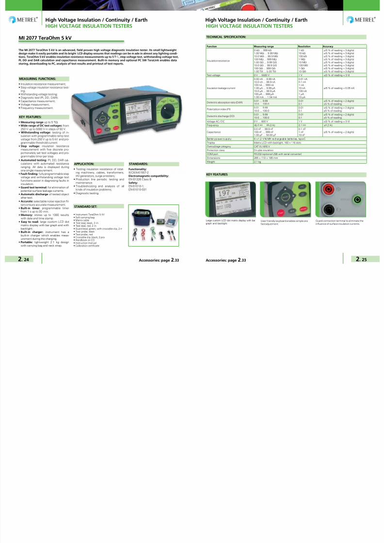
7/25/2019 METREL General Catalog Engl 2015
http://slidepdf.com/reader/full/metrel-general-catalog-engl-2015 50/121
High Voltage Insulation / Continuity / Earth High Voltage Insulation / Continuity / Earth
2. 24 2. 25Accessories: page 2.33 Accessories: page 2.33
MEASURING FUNCTIONS:
• Insulation resistance measurement;• Step voltage insulation resistance test-
ing;• Withstanding voltage testing;• Diagnostic test (PI, DD, DAR);• Capacitance measurement;• Voltage measurement;• Frequency measurement.
KEY FEATURES:
• Measuring range up to 5 TΩ. • Wide range of DC test voltages: from
250 V up to 5000 V in steps of 50 V.• Withstanding voltage: testing of in-
sulation with programmable ramp testvoltage from 250 V up to 5 kV and pro-grammable threshold current.
• Step voltage: insulation resistancemeasurement with five discrete pro-portionately set test voltages and pro-grammable timer per step.
• Automated testing: PI, DD, DAR cal-culations with automated resistanceranging. All data is displayed duringone single measurement.
• Fault finding: fully programmable stepvoltage and withstanding voltage testfunctions assist in diagnosing faults ininsulation.
• Guard test terminal: for elimination ofpotential surface leakage currents.
• Automatic discharge of tested objectafter test.
• Accurate: selectable noise rejection fil-ters ensure accurate measurement.
• Built-in timer: programmable timerfrom 1 s up to 30 min.
• Memory: stores up to 1000 resultswith date and time stamp.
• Easy to read: large custom LCD dotmatrix display with bar graph and withbacklight.
• Built-in charger: instrument has abuilt-in charger which enables meas-urement during the charging.
• Portable: lightweight 2.1 kg designwith carrying bag and neck strap.
The MI 2077 TeraOhm 5 kV is an advanced, field proven high voltage diagnostic insulation tester. Its small lightweightdesign make it easily portable and its bright LCD display ensures that readings can be m ade in almost any lighting condi-tions. TeraOhm 5 kV enables insulation resistance measurements up to 5 TΩ, step voltage test, withstanding voltage test,PI, DD and DAR calculation and capacitance measurement. Built-in memory and optional PC SW TeraLink enables datastoring, downloading to PC, analysis of test results and printout of test reports.
• Instrument TeraOhm 5 kV• Soft carrying bag• Mains cable• Test lead, black, 2 m• Test lead, red, 2 m• Guard lead, green, with crocodile clip, 2 m• Test probe, black• Test probe, red• Crocodile clip, black, 2 pcs• Handbook on CD• Instruction manual• Calibration certificate
STANDARD SET:
APPLICATION:
• Testing insulation resistance of rotat-ing machinery, cables, transformers,HV generators, surge arresters;
• Production line periodic testing andmaintenance;
• Troubleshooting and analysis of allkinds of insulation problems;
• Diagnostic testing.
STANDARDS:
Functionality:IEC/EN 61557-2Electromagnetic compatibility:EN 61326 Class BSafety:
EN 61010-1;EN 61010-031
MI 2077 TeraOhm 5 kV
HIGH VOLTAGE INSULATION TESTERS
TECHNICAL SPECIFICATION:
Function Measuring range Resolution Accuracy
Insulation resistance
0 kΩ … 999 kΩ1.00 MΩ … 9.99 MΩ
10.0 MΩ … 99.9 MΩ
100 MΩ … 999 MΩ
1.00 GΩ … 9.99 GΩ
10.0 GΩ … 99.9 GΩ
100 GΩ … 999 GΩ 1.00 TΩ … 5.00 TΩ
1 kΩ10 kΩ
100 kΩ
1 MΩ
10 MΩ
100 MΩ
1 GΩ
10 GΩ
±(5 % of reading + 3 digits)±(5 % of reading + 3 digits)±(5 % of reading + 3 digits)±(5 % of reading + 3 digits)±(5 % of reading + 3 digits)±(5 % of reading + 3 digits)±(5 % of reading + 3 digits)±(5 % of reading + 3 digits)
Test voltage 0 V … 5500 V 1 V ±(3 % of reading + 3 V)
Insulation leakage current
0.00 nA … 9.99 nA10.0 nA … 99.9 nA100 nA … 999 nA1.00 µA … 9.99 µA10.0 µA … 99.9 µA100 µA … 999 µA1.00 mA … 1.54 mA
0.01 nA0.1 nA1 nA10 nA100 nA1 µA10 µA
±(5 % of reading + 0.05 nA)
Dielectric absorption ratio (DAR)0.01 … 9.9910.0 … 100.0
0.010.1
±(5 % of reading + 2 digits)±5 % of reading
Polarization index (PI)0.01 … 9.9910.0 … 100.0
0.010.1
±(5 % of reading + 2 digits)±5 % of reading
Dielectric discharge (DD)0.01 … 9.9910.0 … 100.0
0.010.1
±(5 % of reading + 2 digits)±5 % of reading
Voltage AC / DC 0 V … 600 V 1 V ±(3 % of reading + 3 V)
Frequency 45.0 Hz … 65.0 Hz 0.1 Hz ±0.2 Hz
Capacitance0.0 nF … 99.9 nF100 nF … 999 nF1.00 µF … 50.00 µF
0.1 nF1 nF10 nF
±(5 % of reading + 2 digits)
Bat ter y p owe r s up pl y 6 x 1 .2 V Ni MH re ch ar ge ab le bat te ri es, typ e C
Display Matrix LCD with backlight, 160 x 116 dots
Overvoltage category CAT III / 600 V
Protection class Double insulation
COM port RS232 (optional USB with serial converter)
Dimensions 265 × 110 × 185 mm
Weight 2.1 kg
KEY FEATURES
Guard connection terminal to eliminate theinfluence of surface insulation currents.
Large custom LCD dot matrix display with bargraph and backlight.
User friendly keyboard enables simple andfast adjustment.
HIGH VOLTAGE INSULATION TESTERS

7/25/2019 METREL General Catalog Engl 2015
http://slidepdf.com/reader/full/metrel-general-catalog-engl-2015 51/121
High Voltage Insulation / Continuity / Earth High Voltage Insulation / Continuity / Earth
2. 26 2. 27Accessories: page 2.33 Accessories: page 2.33
MEASURING FUNCTIONS:
• Insulation resistance measurement;• Voltage measurement;• Frequency measurement.
KEY FEATURES:• Measuring range up to 1 TΩ.
• Analogue scale and digital LCD: measuring results are displayed bothin numeric and analogue form.
• Quick set-up: quick and easy selectionof test voltage (250 V; 500 V; 1 kV; 2,5kV; 5 kV).
• Fast testing: 5 mA current source forquick charging of capacitive load.
• Guard test terminal: for elimination ofpotintial surface leakage currents.
• Automatic discharge of tested objectafter test.
• Safe: high CAT IV / 600 V voltageprotection.
• Easy to read: large bright LCDwith backlight.
• Built-in charger & rechargeable bat-teries: instrument has a built-in chargerand comes complete with a set of re-
chargeable NiMH batteries.• High quality accessories: shielded test
leads are included in a standard set.
• Portable: lightweight 3 kg design with
carry handle and shoulder strap.
APPLICATION:
• Testing insulation resistance of rotat-ing machinery and cables;
• Production line periodic testing andmaintenance;
• Troubleshooting and analysis of allkinds of insulation problems.
STANDARDS:
Functionality:IEC/EN 61557-2Electromagnetic compatibility:EN 61326 class BSafety: EN 61010-1; EN 61010-031
The MI 3202 GigaOhm 5 kV provides quick and accurate testing of insulation resistance. Five test voltages up to 5 kV and1 TΩ resistance measuring range cover most of the industrial and power distribution applications. The large analogue /digital LCD screen with backlight offers easy reading of test results. The instrument is placed in a rugged carrying casewhich allows to use it in harsh environments.
• Instrument GigaOhm 5 kV• Mains cable• 10 kV shielded test lead with probe, black, 2 m• 10 kV shielded test lead with pro be, red, 2 m• 10 kV crocodile clip, 2 pcs (black, red)• Guard lead, green, 2 m• Crocodile clip, green• 6 x 1.2 V NiMH rechargeable batteries, type C
• Handbook on CD• Instruction manual• Calibration certificate
STANDARD SET:
MI 3202 GigaOhm 5 kV
HIGH VOLTAGE INSULATION TESTERS
KEY FEATURES
TECHNICAL SPECIFICATION:
Function Measuring range Resolution Accuracy
Insulation resistance
5 kΩ … 999 kΩ1.00 MΩ … 9.99 MΩ
10.0 MΩ … 99.9 MΩ
100 MΩ … 999 MΩ
1.00 GΩ … 9.99 GΩ
10.0 GΩ … 99.9 GΩ
100 GΩ … 999 GΩ
1 kΩ10 kΩ
100 kΩ
1 MΩ
10 MΩ
100 MΩ
1 GΩ
±(5 % of reading + 3 digits)±(5 % of reading + 3 digits)±(5 % of reading + 3 digits)±(5 % of reading + 3 digits)±(5 % of reading + 3 digits)±(5 % of reading + 3 digits)±(10 % of reading + 3 digits)
Test voltage 0 V … 5500 V 1 V ±(3 % of reading + 3 V)
Voltage AC / DC 0 V … 600 V 1 V ±(3 % of reading + 4 V)
Frequency 45.0 Hz … 65.0 Hz 0.1 Hz ±0.2 Hz
Bat tery power s upply 6 × 1 .2 V NiMH rec ha rgea ble bat teri es , type C
Display Analogue / digital LCD with backlight
Overvoltage category CAT IV / 600 V
Protection class Double insulation
Dimensions 310 x 130 x 250 mm
Weight 3 kg
Guard terminal for connecting shielded testleads
Fast and simple adjustment of the testparameters
Large analogue / digital LCD with backlight
HIGH VOLTAGE INSULATION TESTERS

7/25/2019 METREL General Catalog Engl 2015
http://slidepdf.com/reader/full/metrel-general-catalog-engl-2015 52/121
High Voltage Insulation / Continuity / Earth High Voltage Insulation / Continuity / Earth
2. 28 2. 29Accessories: page 2.33 Accessories: page 2.33
STANDARDS:
Functionality:
IEC/EN 61557 Parts 1,2, 4, 10
IEC/EN 60364
VDE 100
BS 7671 17th edition
CEI 64.8
Electromagnetic compatibility:
IEC/EN 61326-1;
Safety:
IEC/EN 61010-1;
EN 61010 - 031
instrument on metal surfaces enableshands-free operation.
APPLICATION:
• Measurement of insulation resistance
of transformers, motors, cables, ma-
chines, etc;• Testing on CAT IV installations (distri-
bution side of installations, industrialplants, etc);
• Observation of insulation trends;• Testing of PE conductors continuity and
main and supplementary PE connections.
MEASURING FUNCTIONS:
• Insulation resistance with DC voltageup to 2.5 kV;
• Diagnostic test (PI, DAR calculation)• Continuity of PE conductors with 200
mA test current and polarity change;• Continuity of PE conductors with 7
mA test current (continuous measure-ment) without RCD tripping;
• TRMS voltage and frequency.
KEY FEATURES:
• High measuring range: up to 100 GΩ
with test voltage from 100 to 2500 V.• Insulation diagnostics: PI and DAR
calculation for determining if the insu-lation damaged or contaminated.
• Guard test terminal: for elimination ofpotential surface leakage currents.
• Polarity swap: automatic polarity re-versal on continuity test.
• Analogue scale: measuring results aredisplayed in numeric and analogue rep-resentation.
• Custom limits: if limits are set on insu-lation or continuity function then largegreen and red lights of the LEDs willindicate a PASS or FAIL evaluation oftest result.
• Safe: suited for testing on CAT IV in-stallations.
• Built-in charger & rechargeable bat-teries: instrument has a built-in charg-ing circuit and comes complete witha set of rechargeable NiMH batteries.Memory: two level memory structurefor saving of test results and param-eters.
• Downloadable: downloads via RS232or USB cable directly to the PC withthe help of the PC software EuroLinkPRO.
• Easy to use: large bright LCD displayand large buttons enable easy handlingof the instrument (even while wearinggloves).
• Magnetic holder: magnet for fixing
MI 3121H 2,5 kV Insulation / Continuity
The MI 3121H Smartec 2,5 kV Insulation / Continuity is the portable measuring instrument for complete diagnostic testingof insulation and continuity measurements. Due to insulation resistance measurement with the test voltages up to 2.5 kV(measuring range is up to 100 GΩ) and calculation of PI and DAR indexes the instrument is suited for testing insulation ofcable lines, current and voltage transformers, electric motors, etc. Due to configurable limits the instrument enables PASS/ FAIL evaluation of test results which is accompanied with bright green or red light of LEDs. Additional features includemagnetic holder for fixing the tester on the metal surface and built-in charger. The Mi 3121H is compatible with EuroLinkPRO software which enables downloading and analysis of test results and creation of professional test reports.
HIGH VOLTAGE INSULATION TESTERS
Large LCD screen with backlight and PASS /FAIL indicators.
KEY FEATURES
Simple and fast manipulation.
• Instrument Smartec 2,5 kV Insulation /Continuity
• Soft hand strap• Test lead, 2 x 1.5 m• Test probe, 2 pcs (black, red)• Crocodile clip, 2 pcs (black, red)• Power supply adapter + 6 NiMH recharge-
able batteries, type AA• Instruction manual on CD• Short instruction manual
• Handbook on CD• Calibration certificate
STANDARD SET:
Function Measuring range Resolution Accuracy
Insulation resistance (EN 61557-2)
U = 500, 1000, 2500 VDC:R: 0.00 MΩ … 19.99 MΩ 20.0 MΩ … 199.9 MΩ 200 MΩ … 999 MΩ 1.00 GΩ … 4.99 GΩ 5.00 GΩ … 19.99 GΩ 20.0 GΩ … 99.9 GΩU = 100, 250 VDC:R: 0.00 MΩ … 19.99 MΩ 20.0 MΩ … 199.9 MΩ 200 MΩ … 999 MΩ
0.01MΩ0.1MΩ1 MΩ10 MΩ10 MΩ100 MΩ
0.01 MΩ0.1 MΩ1 MΩ
±(5 % of reading + 3 digits)±5 % of reading±5 % of reading±10 % of reading±20 % of reading±20 % of reading
±(5 % of reading + 3 digits)±10 % of reading±20 % of reading
PI, DAR 0.01 … 9.9910.0 … 100.0
0.010.1
±(5 % of reading + 2 digits)±5 % of reading
Continuity 200 mA of PE conductor
with polarity change (EN 61557-4)
0.00 Ω … 19.99 Ω20.0 Ω … 199.9 Ω
200 Ω … 1999 Ω
0.01 Ω0.1 Ω
1 Ω
±(3 % of reading + 3 digits)±5 % of reading
±10 % of readingLow resistance measurement with 7mA test current (continuous measure-ment)
0.0 Ω … 19.9 Ω20 Ω … 1999 Ω
0.1 Ω1 Ω
±(5 % of reading + 3 digits)±10 % of reading
Voltage 0.0 V … 99.9 V100 V … 550 V
0.1 V1 V ±(3 % of reading + 3 digits)
Frequency0.00 Hz … 19.99 Hz20.0 Hz … 199.9 Hz200 Hz … 500 Hz
0.01 Hz0.1 Hz1 Hz
±(0.2 % of reading + 1 digits)
Power supply 6 x 1.2 V rechargeable batteries, type AAOvervoltag e category CAT III / 600 V; CAT IV / 300 V
Protection class Double insulation
COM port RS232 and USB
Dimensions 140 x 230 x 80 mm
Weight 0.85 kg
TECHNICAL SPECIFICATION:
USB and RS232 communication ports.
HIGH VOLTAGE INSULATION TESTERS

7/25/2019 METREL General Catalog Engl 2015
http://slidepdf.com/reader/full/metrel-general-catalog-engl-2015 53/121
High Voltage Insulation / Continuity / Earth High Voltage Insulation / Continuity / Earth
2. 30 2. 31Accessories: page 2.33 Accessories: page 2.33
HVLink PRO
The HVLink PRO software works in conjunction with Metrel newest HV insulation testers, Step Contact Voltage MeasuringSystem and MicroOhms. The software automatically recognizes connected instrument and allows the customer to down-load test results saved on the instrument, review the results, rename and relocate data if needed and print test reports.
KEY FEATURES:
• Automatic recognition of the instru-ment: when connecting your instru-ment to the PC it is automatically rec-ognized by the software.
• Tree view: all the results are repre-
sented in tree view for easy data man-agement.
• Rearranging of structures: the ele-ments of the tree structure can be re-located and renamed.
• R(t) graphs: if graph R(t) was enabledwhen testing with the instrument MI3200 or MI 3201 then it can be plottedand printed with the software.
• Measurement tables: if graph R(t)was enabled when testing with theinstrument MI 3200 or MI 3201 thena table with fixed R(t) values can beviewed and printed.
• Export of test results: test results intext format can be exported to otherprograms (MS Excel, MS Word).
• Automatic Test Report generation: enables automatic generation of TestReport (low, medium and high de-tailed).
PC SW HVLink PRO is compatible with:• MI 3210 TeraOhmXA 10 kV
• MI 3200 TeraOhm 10 kV• MI 3201 TeraOhm 5 kV Plus• MI 3295 Step Contact Voltage Meas-
uring System• MI 3252 MicroOhm 100A
PASSWORD PROTECTION:
PC SW HVLink PRO is password pro-tected for the following instruments:• MI 3200• MI 3201
ORDERING INFORMATION:
• A 1275 PC SW HVLink PRO with USBand RS232-PS/2 cable
Test report
PC SOFTWARE
R(t) graph can be drawn for HV Insula-tion Resistance measuring functions.
Table with fixed R(t) values can be drawnfor HV Insulation Resistance measuringfunctions.
User friendly interface with tree viewdata structure and full, medium or lowrepresentation of test results.
PC SOFTWARE

7/25/2019 METREL General Catalog Engl 2015
http://slidepdf.com/reader/full/metrel-general-catalog-engl-2015 54/121
High Voltage Insulation / Continuity / Earth High Voltage Insulation / Continuity / Earth
2. 32 2. 33Accessories: page 2.33 Accessories: page 2.33
The MI 3299 High voltage Demonstration Box 10 kV has been developed for demonstration purposes at high voltageinsulation diagnostics. It simulates typical electrical insulation usually met in the industrial environment. It is equippedwith high quality resistors in different ranges, high voltage capacitors and a discharge facility to simulate a breakdownphenomenon in gases. Additionally measurements of polarization index (PI), dielectric discharge (DD) and dielectric ab-sorption ratio (DAR) can be demonstrated. Packed with all these features the demonstration box is also well suited forbasic calibration of DC high voltage insulation resistance measuring instruments.
KEY FEATURES:• 10 kV rated resistors with very low
voltage coefficient.• Resistive decade with 200 kΩ, 500
MΩ, 200 GΩ and 2 TΩ resistors.• HV capacitors in 2.5 µF and 5 nF range.• Built-in spark gap and gas discharge
tube.• Demonstration of insulation break-
down in gases is possible.• Two models of insulation material (good
and bad cables) enable the demonstra-tion of real insulation behavior underhigh DC voltage.
• Demonstration box is put in the strongrugged case with handle for comfortablecarrying.
APPLICATION:
• Demonstration of insulation diagnos-tics measurement with DC test volt-age;
• Demonstration of functionality of HVinsulation measuring instruments;
• Training centres, schools, laboratories;• Basic calibration of DC high voltage in-
sulation testers.
STANDARDS:
Safety:EN 61010-1
• HV demo BOX 10 kV
• HV test leads, 2 pcs
• Instruction manual
• Handbook on CD
• Calibration certificate
STANDARD SET:
TECHNICAL DATA:
Dimensions 440 × 320 × 110 mm
Weight 4 kg
MI 3299 HV demo BOX
DEMONSTRATION BOARD
PhotoPart
numberDescription Target application
M I 3 2 9 5
M I 3 2 5 2
M I 3 2 5 0
M I 3 2 4 2
M I 3 2 1 0
M I 3 2 0 0
M I 3 2 0 5
M I 3 2 0 1
M I 2 0 7 7
M I 3 2 0 2
M I 3 1 2 1 H
MI3295M
Set
Step Contact MeterMeasuring Set
Additional MI 3295M Set for simultaneous measure-ments of step voltage and contact voltage on differenttest points. Set includes instrument MI 3295M, testlead, 2 x 3 m, soft carrying bag, soft carrying neck belt,NiMH battery, type AA, 6 pcs, Power supply adapter.
– – – – – – – – – –
A 1014 Test probe, blackTest probe with ∅ 4 mm connection is suitable forperforming measurements both in mains outlets andin situations when no schuko outlet is present.
– – – – – – – – – –
A 1013 Crocodile clip, blackCrocodile clip assures secure and permanent contactduring the measurement on bus bars, fixing screws,etc.
– – – – – – – – –
A 1064 Crocodile clip, redCrocodile clip assures secure and permanent contactduring the measurement on bus bars, fixing screws,etc.
– – – – – – – – – –
A 1309 Crocodile clip, greenCrocodile clip assures secure and permanent contactduring the measurement on bus bars, fixing screws,etc.
– – – – – – –
S 2036HV crocodil clip, 2 pcs(red, black)
10 kV crocodile clips for HV insulation resistancemeasurement assure secure and permanent contactduring the measurement on bus bars, fixing screws,etc.
– – – – –
A 10461.2 V NiMH battery,type C, 6 pcs
A s et o f 6 p ieces of rec ha rgea ble bat teri es , type C . – – – – – – – –
S 20541.2 V NiMH battery,type D, 6 pcs
A set of 6 pieces of rechargeable batteries, type C. – – – – – – – – – –
A 1169Fast charger for AA,C, D and 9 V blockbatteries
Fast battery charger for up to 12 pcs AA, 6 pcs C orD rechargeable batteries, 4 pcs 9 V block batteries.
– – –
A 1017Communication cableRS232
RS232 interface cable for connecting the instrumentwith the PC.
– – – – – –
A 1171RS232 / USB adapterwith 1 m cable
RS232 / USB adapter for instruments without USBcomunication port.
– – – – – – – – – –
A 1056PC SW TeraLink withRS232 cable
PC Software TeraLink supplied with RS232 interfacecable supports test results downloading and creationof test reports.
– – – – – – – – – –
Selection Guide for HV Accessories
Option – Not available

7/25/2019 METREL General Catalog Engl 2015
http://slidepdf.com/reader/full/metrel-general-catalog-engl-2015 55/121
High Voltage Insulation / Continuity / Earth High Voltage Insulation / Continuity / Earth
2. 34 2. 35Accessories: page 2.33 Accessories: page 2.33
PhotoPart
numberDescription Target application
M I 3 2 9 5
M I 3 2 5 2
M I 3 2 5 0
M I 3 2 4 2
M I 3 2 1 0
M I 3 2 0 0
M I 3 2 0 5
M I 3 2 0 1
M I 2 0 7 7
M I 3 2 0 2
M I 3 1 2 1 H
A 1275 PC SW HVLink PRO
HVLink PRO is a downloading and data managementPC software with R=f(t) graph printing functionality(for HV insulation testers). It comes delivered withRS232 and USB communication cables.
– – – – –
A 1291PC SW EuroLink PROwith USB and RS232-PS/2 cable
PC Software EuroLink PRO enables downloading andtest results management and printing of test reports.Delivered with RS232-PS/2 and USB communicationcables.
– – – – – – – – – –
A 1333Resistor SHUNT,750 µΩ
Resistor SHUNT is used for testing correctness ofmirco ohmmeters.
– – – – – – – – –
A 1323Current and potentialearth spike (with 3mlead)
Auxiliary current earth spikes for decreasing the earthresistance and potential earth spike for specific earthmeasurements.
– – – – – – – – – –
A 1353Step voltage probe(25 kg), 2 pcs
Additional voltage probes for step voltage measure-ments.
– – – – – – – – – –
S 2053 Step voltage platesLight replacement for 25kg Step voltage probes A1353.
– – – – – – – – – –
S 2058 Insulation test plates
Two in one: Test plates for measurement of floor andwall insulation, ∆625 cm2 (acc. to EN 60364-6) andmeasurement of semi conductivity, 2,5 kg, Ø65 mm(acc. to EN 61340-5-1).
– – – – – –
A 1012 Test l ea d, g reen, 4 m Extension tes t l ea d. – – – – – – –
A 1154 Test lead, black, 4 mExtension test lead for earth and continuity measure-ments.
– – – – – – – – – –
A 13192.5 kV test lead,3 x 1.5 m
3-wire test lead with GUARD connection for insula-tion resistance measurements with test voltage upto 2,5 kV. Recommended to be used when measur-ing high insulation resistances (>10 GΩ).
– – – – – – – – – –
A 1153 Test lead, black, 20 mExtension test lead for earth and continuity measure-ments.
– – – – – – – – – –
A 1383Temperature probewith 2 m cable
Temperature probe with measuring range from -55°C to +125 °C for measurement of ambient tempera-ture.
– – – – – – – – – –
Selection Guide for HV Accessories
Option – Not available
Selection Guide for HV Accessories
PhotoPart
numberDescription Target application
M I 3 2 9 5
M I 3 2 5 2
M I 3 2 5 0
M I 3 2 4 2
M I 3 2 1 0
M I 3 2 0 0
M I 3 2 0 5
M I 3 2 0 1
M I 2 0 7 7
M I 3 2 0 2
M I 3 1 2 1 H
A 1437Test lead with Kelvinprobe
Test lead with Kelvin probe for fast resistance meas-urements.
– – – – – – – – –
A 1407Test cable Kelvin500 A, 2,5 m
Test cable with 500 A Kelvin clamps for easy and ac-curate resistance measurements with MI 3242.
– – – – – – – – – –
A 1408Test cable Kelvin,2,5 m
Test cable with Kelvin clamps for easy resistancemeasurements with MI 3242.
– – – – – – – – – –
S 1072Continuity test lead,with crocodile clip,2 x 2.5 m, 2 pcs
Kelvin test probes with crocodile clips and protectionshield as lightweight alternative to clips within thestandard set.
– – - – – – – – – –
S 2046
Current test lead withinsulated crocodileclip, 5 m, 25 mm2,2 pcs
100 A current test lead with insulated crocodile clip forperforming accurate resistance measurements with MI3252.
– – – – – – – – – –
S 2052Current test lead withcrocodile clip, 10 m,50 mm2, 2 pcs
Extended 100 A current test leads for accurate meas-urements with MI 3295.
– – – – – – – – – –
S 20035 kV test lead set,2 m, 2 pcs
5 kV test lead set, including 2 test leads and 2 croco-dil clips, for safe insulation testing.
– – – – – – – – – –
S 202910 kV shielded testlead, 8 m, 2 pcs
10 kV shielded test leads improve accuracy of HVinsulation resistance measurement in environmentswith high content of external electromagnetic inter-ferences.
– – – – – –
S 203010 kV shielded testlead, 15 m, 2 pcs
10 kV shielded test leads improve accuracy of HVinsulation resistance measurement in environmentswith high content of external electromagnetic inter-ferences.
– – – – – –
S 20395 kV shielded testlead, 15 m, 2 pcs
5 kV shielded test leads for MI 2077 improve accuracyof HV insulation resistance measurement in environ-ments with high content of external electromagneticinterferences.
– – – – – – – – – –
S 20425 kV shielded testlead with test probe,10 m, 2 pcs
Set of 5 kV shielded test leads with test probe andGuard test lead with crocodile clip for MI 2077 im-proves accuracy of HV insulation resistance measure-ment in environments with high content of externalelectromagnetic interferences.
– – – – – – – – – –
S 20445 kV shielded testlead with test probe,15 m, 2 pcs
5 kV shielded test leads with test probe improve ac-curacy of HV insulation resistance measurement in en-vironments with high content of external electromag-netic interferences.
– – – – – – – – – –
Option – Not available

7/25/2019 METREL General Catalog Engl 2015
http://slidepdf.com/reader/full/metrel-general-catalog-engl-2015 56/121
Accessories: page 3.34
High Voltage Insulation / Continuity / Earth
2. 36 Accessories: page 2.33
PhotoPart
numberDescription Target application
M I 3 2 9 5
M I 3 2 5 2
M I 3 2 5 0
M I 3 2 4 2
M I 3 2 1 0
M I 3 2 0 0
M I 3 2 0 5
M I 3 2 0 1
M I 2 0 7 7
M I 3 2 0 2
M I 3 1 2 1 H
A 1271Small soft carryingbag
Small soft carrying bag for transport and storage oftest instrument or accessories.
– – – – – – –
A 1006 Soft carrying bagLarge soft carrying bag for transport and storage oftest instrument and belonging accessories.
– – – – – – – – –
Selection Guide for HV Accessories
GOOD TO KNOW Testing the safety of electrical appliances 3 - 02
PAT TESTERSSelection Guide for PAT testers 3 - 05
MI 3305 OmegaGT Plus and MI 3304 BetaGT Plus 3 - 06MI 3310 25A SigmaGT and MI 3310 SigmaGT 3 - 08MI 3309 BT DeltaGT 3 - 10MI 3311 GammaGT 3 - 12
OTHER INSTRUMENTS / ADAPTERS / ACCESSORIESA 1322 and A 1422 Active 3-phase Adapter 3 - 14
DEMONSTRATION BOARDMI 3300 Portable Appliance Simulation Board 3 - 16
GOOD TO KNOW Testing the safety of electrical appliances, machines and switchboards 3 - 18MACHINE AND SWITCHBOARD TESTERSSelection Guide for Machine and Switchboard testers 3 - 21 MI 3394 CE MultiTesterXA NEW 3 - 22
MI 2094 CE MultiTester 3 - 24MI 3321 MultiServicerXA 3 - 26MI 2170 MultiServicer 3 - 28
PC SOFTWAREPATLink PRO and PATLink PRO Plus 3 - 30A 1433 PATLink Android 3 - 32A 1434 aPATLink Android 3 - 33
Selection Guide for PAT Accessories 3 - 34
A p p l i a n c e / M a c h i n e / S w i t c h b o a r d S a f e t y
I n - s e r v i c e I n s p e c t i o n a n d T e s t i n g o f E l e c t r i c a l E q u i p m e n t
MEASURING INSTRUMENTS AND TESTERS
Appliance / Machine / Switchboard Safety
CATALOGUE 2015

7/25/2019 METREL General Catalog Engl 2015
http://slidepdf.com/reader/full/metrel-general-catalog-engl-2015 57/121
Appliance / Machine / Switchboard Safety Appliance / Machine / Switchboard Safety
3. 2 3. 3Accessories: page 3.34 Accessories: page 3.34
Find out more about testing safety ofelectrical equipment.Primary goal of testing safety of elec-trical equipment is to use all electricalequipment without danger. Common ac-cidents caused by electrical equipmentare:• Injuries through electric shock caused
by malfunctioned equipment;• Injuries through overheated equip-
ment;• Fire and explosions.
To prevent risk and possible dangercaused by using electrical appliancesand other equipment appropriate safetytesting procedure should be performed.Testing of electrical equipment is notregulated the same way in all countries.For instance in Germany, UK, Australiatesting of all electrical equipment isstrictly regulated by law. Through theirpositive experience it can be assumedthat other countries will follow in the fu-ture.
Safety of electrical equipment dependson different factors which can improveor worsen the safety level.
Remaining risk
Periodic retests
Correct service and maintenance
Correct use
Independent certification
Type test
Adequate design
Consideration of safety standards
Age
Wear
Harshconditions
Damage
Types of safety tests of electrical equip-ment are:• Type testing;• End of line testing;• Maintenance testing;• Periodic testing.
According to the standards electricalequipment is divided in:• Electrical appliances;• Electrical equipment in medical use;• Electrical machines;• Electrical switchgears.
Classification of appliances by field ofuse:• Laboratory equipment;• Measuring and regulating equipment;
Testing PAT Testing PAT
GOOD TO KNOW GOOD TO KNOW
• Power supplies;• Heating appliances;• Handheld tools;• Luminaries;• Consumer electronic;• Information and communication tech-
nology (computers, fax machines,scanners, etc.);
• Prolongation cords, IEC supply cords;• Appliances for medical use.
Classification of appliances by protec-tion classes:According to the design electrical equip-ment can be divided in three classes. Inthe table below the differences betweenclasses are described.
Class I II III
Marking no III
Connection toprotection (PE)conductor ofthe installation.
yes
all accessible
metal parts
(case etc.) are
connected to
the PE connec-
tion.
nono connection
to mains
Basic insulation p er fo rmed p er fo rmedperformed /
looser limits
Supplementaryor reinforcedinsulation
not needed
in general,
needed if there
are acces-
sible unearthed
metal parts 1)
performed not needed
Supply cordthree pole (L,N,
PE)
can be two
poletwo pole
Notes
installation
must have ad-
equate earthing
resistance
must be
supplied from
a SELV (safety
low voltage)
source, typically
12 V or 24 V
Portable appliances - measurements:Visual checkVisual test of the equipment is intendedto confirm that there are no visible signsof damage or defects. Result of visualtest can be stored on most of MetrelPAT testers for future reference.
Earth bond (continuity of protectiveconductor) testWith the earth bond test following is de-termined:• That the contacts between accessible
metal parts and PE conductor are firm.• That PE wire in the appliance supply
cord is undamaged.• That there are no signs of poor con-
tacts, corrosion etc.
Earth bond test
Test signal is applied between PE pinof supply cord and accessible earthedmetal parts.
Insulation resistanceInsulation resistance between live con-ductors and all accessible metal parts(earthed and isolated) is checked. Thistest discloses faults caused by pollution,moisture, deterioration of insulation ma-terial etc.
Insulation resistance test for Class I device
High DC voltage test signal is applied be-tween connected live pins and PE con-tact of supply cord. Unearthed accessi-ble metal parts are NOT included in thistest and are measured as Class II items.
Insulation resistance test for Class II device
High DC voltage test signal is appliedbetween connected live pins and acces-sible isolated metal part.
Substitute leakage testIn this test the live and neutral conduc-tors of the appliance are shorted togeth-er and voltage of 30 - 50 V AC is appliedbetween this point and either the earthconductor (class I) or the probe con-nected to any exposed conductive part(class I and class II). The test measureshow much current passes from the liveconductors into the test point.
Substitute leakage test for Class I device
AC test signal is applied between con-nected live pins and PE contact of supplycord. Isolated accessible metal parts areNOT included in this test and are meas-
ured as Class II items.
Substitute leakage test for Class II device
AC test signal is applied between con-nected live pins and accessible isolatedmetal part.
Leakage current testsIn this test the sum of leakage currentscaused by appliance insulation resist-ances (resistive currents through the in-sulation material, fault currents throughdecreased insulation) and capacitances(capacitive leakage current) is checked.Excessive leakage currents are mostoften caused by deterioration of theappliance insulation (pollution, ageing,moisture) or faults in mains circuits ofappliances.
In general three leakage currents aremeasured: the differential leakage cur-
rent, the PE conductor (direct) leakagecurrent and the touch leakage current.
PE conductor lekage test
PE conductor leakage current test for Class I device
Appliance must be powered on. Thecurrent flowing through appliance PEconductor is measured. Appliance mustbe placed isolated against ground. Un-earthed accessible metal parts are notincluded in this test. They are consid-
ered as class II parts and are checked inthe Touch Leakage test.
Differential leakage current testDifferential leakage measures the dif-ference in current between the live andneutral cable which provides a true valueof how much current the appliance leaksto ground.
Differential leakage current test for Class I device
Appliance must be powered on. Theleakage current is measured as the dif-ference of currents through L and Nconductors. Unearthed accessible metalparts are not included in this test. Theyare considered as class II parts and arechecked in the Touch Leakage test.
Touch leakage testLeakage leakage current is a current thatwould flow via the isolated accessiblemetal part (if touched) through body toground are measured in this test.
Touch leakage current test for Class II device
Appliance must be powered on. Thecurrent through the isolated accessiblemetal parts is measured (each part sepa-rately).
Polarity testPolarity test checks the correctness ofpolarity of IEC leads, prolongation cordsetc is checked. With this test shorts,crossed and opened wires in cords canbe found.
Polarity test
Measurement of load and leakagecurrents with current clampsAdvantages of clamp measurements are:• Measured electrical equipment does
not need to be disconnected from themains.
• Selective current tests can be per-formed by embracing individual con-ductors.
• Individual currents can be measuredwithout disconnections.
Current clamps are best suited for:
• functional testing of fixed installed ap-pliances;• functional testing of appliances with
nominal currents >16 A;• troubleshooting of current paths in ap-
pliances.
Current measurement with current clamps
Appliance must be powered on. Byembracing separate conductors load orleakage currents can be measured.
Functional testFunctional check explores if the appli-ance is working properly. The use ofmore sophisticated measuring instru-ments permits load testing, which is aneffective way of determination if thereare faults in the appliance.
Functional test
PRCD testThis test checks how long it takes for aportable RCD to trip out in the case thata fault occurs.
PRCD testing
0 %
100 %

7/25/2019 METREL General Catalog Engl 2015
http://slidepdf.com/reader/full/metrel-general-catalog-engl-2015 58/121
Appliance / Machine / Switchboard Safety Appliance / Machine / Switchboard Safety
3. 4 3. 5Accessories: page 3.34 Accessories: page 3.34
Testing PAT
GOOD TO KNOW
Part No.M I 3 30 5 M I 33 04 M I 3 31 0 2 5A M I 3 31 0 M I 3 309 MI 3 31 1
OmegaGT Plus BetaGT Plus SigmaGT SigmaGT BT DeltaGT GammaGT
MEASUREMENTS
Continuity 200 mA Continuity 10 A − − −Continuity 25 A − − −Insulation resistance 250 VDC
Insulation resistance 500 VDC
Differential leakage current −Touch leakage current −Substitute leakage current
Leakage current measurements withoptional clamp
−
Flash test − − − − −PRCD testing −Polarity test (IEC lead test)
Functional (load) test −Voltage TRMS − −
ADDITIONAL FEATURES
PASS / FAIL evaluation
Mains supply check
Built-in Checkbox − − Option Option −
Graphical LCD
Graphical on-line help
Backlight
Real time clock
QWERTY keyboard − −Auto testing (organizer, custom autotests)
Barcode shortcut auto testing
Communication ports USB / RS232 / BLUETOOTH / / − / / − / / / / − / / / / Option“Test and tag” (barcode scanner + label printer)
Data download to PC
Project upload from PC − −Trend (compare) on instrument’s LCD − −Trend with PC SW PATLink PRO Plus − −Number of memory locations 6500 6500 6000 6000 1500 1500STANDARD / OPTIONAL ACCESSORIES
Barcode scanner Option Option Option Option Option OptionBarcode label printer − − Option Option Option OptionQR label printer Option Option Option Option Option OptionReceipt printer Option Option Option Option Option OptionBasic PC SW OptionAdvanced PC SW Option Option Option Option Option OptionAndroid APP − − Option − Option OptionGENERAL DATA
Weight 8.4 kg 5 kg 0.86 kg 0.86 kgDimensions 345 x 160 x 335 310 x 130 x 250 140 x 80 x 230 140 x 80 x 230
Selection Guide for PAT testers
PAT TESTERS
PRCD testing
Active polarity testThis test provides testing of PRCD pro-tected cords while voltage is applied totested object.
Active polarity test
AutosequencesAll Metrel PAT testers contain built-in
predefined test sequences which are
specified sets of measurements, lim-
its and test parameters. To select the
correct test sequence first the type
and class of appliance must be deter-
mined. Then all safety relevant acces-
sible conductive parts must be found.
After that the test sequence, test lim-
Guide through Verification on Low-voltage electrical installations : VDE 701/702
its and parameters must be selected.
It is of a great advantage if this can be
made automatically by the measuring
instrument.
Custom test sequences
In case of testing unusual appliances
or appliances that require a special
method of testing that is not included
in the standard autosequences cus-
tom defined test sequences can be
used.
Project uploading
When retesting a site or location, pro-
ject uploading allows previously saved
information to be reloaded onto the
PAT tester to speed up testing and en-
able trend comparison.
Trend comparison
Trend comparison allows test informa-
tion from different dates to be com-
pared in order to discover if deterio-
ration is occurring in an appliance. In
case the deterioration was found, the
test engineer can make an informed
decision as to if the frequency of test-
ing and inspection is sufficient for the
appliance.

7/25/2019 METREL General Catalog Engl 2015
http://slidepdf.com/reader/full/metrel-general-catalog-engl-2015 59/121
Appliance / Machine / Switchboard Safety Appliance / Machine / Switchboard Safety
3. 6 3. 7Accessories: page 3.34 Accessories: page 3.34
MI 3305 OmegaGT Plus and MI 3304 BetaGT Plus
MEASURING FUNCTIONS:
• Continuity tests (200 mA,10 A, 25 A);• Insulation resistance;• Substitute leakage current;• Differential leakage current;• Touch leakage current;• IEC cord polarity test;• Leakage and load TRMS current
measurement with current clamp.• Portable RCD testing;• HV Flash test (MI 3305 only);• Functional test.
KEY FEATURES:
• Autosequencing: 24 pre-set autose-quences and custom prepared autose-quences speed up testing and ensurethat no tests are missed.
• Automated: automatic testing andPASS / FAIL evaluation of test resultsaccording to appropriate standard.
• Project uploading: previous test datacan be uploaded for fast retesting ofthe appliance.
• Scan and test: optional barcoding sys-tem and PASS / FAIL barcode label print-ing make retesting quick and simple.
• RFID: support for advanced RFID iden-tification system.
• User friendly: large LCD screen, fullQWERTY keyboard, help screens and
warnings make the instrument an ex-tremely easy to use.• Multi-tasking: instrument performs con-
tinuity tests with different test currents,250 V and 500 V insulation tests, differ-ential /substitute / touch leakage mesure-ments, functioanal and polarity tests.
• Flash test: dielectic strength test afterrepair safety testing (MI 3305 only).
• PRCD testing: instrument enablesmeasurement of trip-out time of port-able RCDs.
• Clamp leakage current measure-ment: quick measurement of leakagecurrent with current clamps directlyon power supply cable without discon-nection of appliance from mains.
• Trend functionality: test results canbe uploaded from PC to the instrumentfor comparison between old and new
test results on-site.• Downloadable: up to 6500 test re-
sults with measuring parameters canbe stored in two level memory anddownloaded to the PC with the help ofPC SW PATLink PRO.
• PC SW PATLink PRO included in thestandard set enables downloading, view-ing, printing of test results and exportingof data to spreadsheet applications.
• PC SW PATLink PRO Plus enables ad-vanced analysis of test results, uploadof structures and data upload to theinstrument for on site comparison ofold and new results, upload of pre-pro-grammed custom autosequences andcreation of professional test reports.
APPLICATION:
• Professional PAT testing;• General PAT testing;• Factory / warehouse PAT testing;• After repair PAT safety testing.
STANDARDS:
Functionality:IEC 60335-1; IEC 60598-1; IEC 60745;IEC 60745; VDE404-1; VDE404-2;VDE 0701; VDE 0702Electromagnetic compatibility:EN 61326Safety: EN 61010-1; EN 61010-031
The innovative MI 3305 OmegaGT Plus and MI 3304 BetaGT Plus are a high-class instruments intended for electricalsafety testing of a wide range of portable electrical appliances, IT equipment, IEC cords and portable RCDs accordingto IEC/EN and VDE standards. This portable, self-contained and durable instruments can be moved between sites withminimum time and effort. The large, bright LCD screen enables work with the instrument in almost all lighting condi-tions. New features including portable RCD testing, clamp leakage current measurement, flash test (MI 3305 only),project uploading, recall and retest functions, fixed appliance test ports, optional PASS/FAIL label printing and on-sitetest result comparison make this instruments perfect for PAT testing in almost any situation.
PAT TESTERS
TECHNICAL SPECIFICATION:
STANDARD SET:
MI 3305 or MI 3304• Instrument OmegaGT Plus or BetaGT Plus• Continuity / Leakage cable• PRCD cable• Flash cable (MI 3305 only)• PC SW PATLink PRO• RS232 cable• USB cable• Crocodile clip, green• Crocodile clip, black
• Test probe, green• Test probe, black• Test lead, green 1.5 m• Test lead, black 1.5 m• Instruction manual• Calibration certificate
Function Measuring range Resolution Accuracy
PE continuity (10 A, 25 A)0.00 Ω …1.99 Ω2.00 Ω …19.99 Ω
0.01 Ω0.01 Ω
±(5 % of reading + 3 digits)±(10 % of reading)
PE continuity (200 mA)0.00 Ω … 1.99 Ω
2.00 Ω … 9.99 Ω 10.0 Ω … 19.9 Ω
0.01 Ω
0.01 Ω
0.1 Ω
±(5 % of reading + 3 digits)±(5 % of reading + 5 digits)±(5 % of reading + 5 digits)
Insulation resistance (250 VDC, 500 VDC)
0.000 MΩ … 0.500 MΩ0.501 MΩ … 1.999 MΩ
2.00 MΩ … 19.99 MΩ
20.0 MΩ … 199.9 MΩ
0.001 MΩ0.001 MΩ
0.01 MΩ
0.1 MΩ
±(10 % of reading + 5 digits)±(5 % of reading + 3 digits)±(5 % of reading + 3 digits)±(5 % of reading + 3 digits)
Substitute leakage current 0.00 mA … 19.99 mA 0.01 mA ±(5 % of reading + 5 digits)
Touch leakage current 0.00 mA … 1.99 mA 0.01 mA ±(10 % of reading + 5 digits)
D if fer en ti al l eakag e cu rr ent 0 .0 0 mA … 9 .9 9 mA 0. 01 mA ±( 5 % of r ead ing + 5 d ig it s)
Functional test: apparent power 0.00 kVA … 4.00 kVA 0.01 kVA ±(5 % of reading + 3 digits)
Current with clamp-on adapter
0.00 mA … 9.99 mA10.0 mA … 99.9 mA100 mA … 999 mA1.00 A … 9.99 A10.0 A … 24.9 A
0.01 mA0.1 mA1 mA0.01 A0.1 A
±(5 % of reading + 5 digits)
Flash insulation test (MI 3305 only) 0.00 mA … 2.50 mA 0.01 mA ±(5 % of reading + 5 digits)
Portable RCD: trip-out time(I∆N= 10 mA, 15 mA, 30 mA)
0 ms … 1999 ms (½xI∆N)0 ms … 300 ms (I∆N)0 ms … 40 ms (5xI∆N)
1 ms1 ms1 ms
±3 ms
Polarity test Test voltage < 50 VAC
Power supply 115 V / 230 V, 50 Hz / 60 Hz
Overvoltage category CAT II / 300 V
Protection class I
COM port RS232 and USB
Dimensions 345 x 160 x 335 mm
Weight 8.4 kg
Fast and easy access to test procedure:select the auto test and press START.
Input / output ports:• Barcode reader• Printer• PC
KEY FEATURES
PAT TESTERS
MI 3305

7/25/2019 METREL General Catalog Engl 2015
http://slidepdf.com/reader/full/metrel-general-catalog-engl-2015 60/121
Appliance / Machine / Switchboard Safety Appliance / Machine / Switchboard Safety
3. 8 3. 9Accessories: page 3.34 Accessories: page 3.34
MI 3310 25A SigmaGT and MI 3310 SigmaGT
PAT TESTERS
MEASURING FUNCTIONS:
• Earth bond resistance with 10 A, 25 A(MI 3310 25A);
• Continuity test with 200 mA;
• Insulation resistance;• Insulation resistance of isolated ac-cessible conductive parts;
• Substitute leakage current;• Substitute leakage current of isolated
accessible conductive parts;• Differential leakage current;• Touch leakage current;• IEC cord polarity test;• Leakage and load currents with cur-
rent clamp;• RCD and portable RCD testing;• Functional test.
KEY FEATURES:
• Autosequencing: pre-programmableVDE compatible autosequences, up to50 custom prepared autosequencesand barcode autotests speed up testingand ensure that no tests are missed.
• Active polarity: innovative solution fortesting of RCD protected cords whilevoltage is applied to the tested item.
• Dual powered: instrument can bepowered from both internal batteryand mains supply (115 V and 230 V).
• Fixed appliance testing: additional in-puts and optional accessories enabletesting of fixed installed appliances.
• Scan and test: optional barcoding sys-
tem and PASS / FAIL barcode label print-ing make retesting quick and simple.• RFID: support for advanced RFID iden-
tification system.• Project uploading: previous test data can
be uploaded for fast retesting of the object.• Trend functionality: test results can
be uploaded from PC to the instrumentfor comparison between old and newtest results on site.
• Memory: up to 6000 test results withparameters can be stored into memoryand downloaded to the PC with thehelp of PC SW PATLink PRO.
• User friendly: large LCD screen, fullQWERTY keyboard, help screens andwarnings make handling the instru-ment very simple and clear.
• Clamp leakage current measurement: quick measurement of leakage currentwith current clamps directly on powersupply cable without disconnection of
appliance from mains.• RCD testing: instrument enables test-ing of parameters of RCDs and port-able RCDs.
• Bluetooth: enables communicationwith PC, printers, and Android devices.
• Android application: enables ad-vanced data management, use ofsmart phones camera for scanning QRand bar-code.
• PC SW PATLink PRO included in thestandard set enables downloading,viewing, printing of test results andexporting of data to spreadsheet ap-plications.
• PC SW PATLink PRO Plus enables ad-vanced analysis of test results, uploadof structures and data upload to theinstrument for on site comparison ofold and new results, upload of pre-pro-grammed custom autosequences andcreation of professional test reports.
APPLICATION:
• Professional PAT safety testing;
• General PAT safety testing;
• Multi-location PAT safety testing.
STANDARDS:
Functionality:
VDE 0404-1; VDE 0404-2; VDE 0701-
0702; AS / NZS 3760; NEN 3140
Electromagnetic compatibility:
EN 61326-1
Safety:
EN 61010-1; EN 61010-031; EN 61010-2-032
The MI 3310 / MI 3310 25A SigmaGT is a multifunctional portable test instrument intended to perform all measure-ments for complete testing the electrical safety of portable electrical equipment. Along with numerous features likedual power supply support, built-in battery charger, lightweight design, large bright LCD, soft Qwerty keypad, internalmemory for up to 6000 results and Bluetooth technology, the instrument offers innovative solution for RCD protectedcords testing and enables testing of fixed appliances. Powerful data management PC software PATLink PRO enablesupload and download of test results and parameters for further data handling, trend analysis and test report creation.
PAT TESTERS
TECHNICAL SPECIFICATION:
STANDARD SET:
MI 3310• Instrument MI 3310 SigmaGT• Small soft carrying bag• Test lead, black, 1.5 m• Crocodile clip, black• Test probe, black• IEC test cable, 2 m• Mains cable 16 A• NiMH rechargeable batteries, type C, 6 pcs• PC software PATLink PRO
• RS232 cable• USB cable• Instruction manual on CD• Short instruction manual• Calibration certificate
Function Measuring range Resolution Accuracy
Earth bond resistance, 10 A, 25 A(MI 3310 25A only)
0.00 Ω …1.99 Ω
2.00 Ω …19.99 Ω
0.01 Ω
0.01 Ω
±(5 % of reading + 3 digits)±10 % of reading
PE continuity, 200 mA0.00 Ω … 1.99 Ω
2.00 Ω … 9.99 Ω 10.0 Ω … 19.9 Ω
0.01 Ω
0.01 Ω
0.1 Ω
±(5 % of reading + 3 digits)±10 % of reading±10 % of reading
Insulation resistance (250 VDC, 500 VDC)
0.000 MΩ … 0.500 MΩ
0.501 MΩ … 1.999 MΩ
2.00 MΩ … 19.99 MΩ
20.0 MΩ … 199.9 MΩ
0.001 MΩ
0.001 MΩ
0.01 MΩ
0.1 MΩ
±(10 % of reading + 5 digits)±(5 % of reading + 3 digits)±(5 % of reading + 3 digits)±(5 % of reading + 3 digits)
Substitute leakage current 0.00 mA … 19.99 mA 0.01 mA ±(5 % of reading + 5 digits)
Touch leakage current 0.00 mA … 3.99 mA 0.01 mA ±(10 % of reading + 5 digits)
D if fer en ti al l eakag e cu rr ent 0 .0 0 mA … 9 .9 9 mA 0. 01 mA ±( 5 % of r ead ing + 5 d ig it s)
Functional test: apparent power 0.00 kVA … 4.00 kVA 0.01 kVA ±(5 % of reading + 3 digits)
Current with current clamp
0.00 mA … 9.99 mA10.0 mA … 99.9 mA100 mA … 999 mA1.00 A … 9.99 A10.0 A … 24.9 A
0.01 mA0.1 mA1 mA0.01 A0.1 A
±(5 % of reading + 10 digits)±(5 % of reading + 5 digits)±(5 % of reading + 5 digits)±(5 % of reading + 5 digits)±(5 % of reading + 5 digits)
Portable RCD: trip-out time(I∆N= 10 mA, 15 mA, 30 mA)
0 ms … 300 ms (½xI∆N)0 ms … 300 ms (I∆N)0 ms … 40 ms (5xI∆N)
1 ms1 ms1 ms
±3 ms
RCD: trip-out time(I∆N= 10 mA, 15 mA, 30 mA)
0 ms … 300 ms (½xI∆N)0 ms … 300 ms (I∆N)0 ms … 40 ms (5xI∆N)
0.1 ms0.1 ms0.1 ms
±3 ms±3 ms±1 ms
Polarity test Test voltage < 50 VAC
Power supply 6 x 1.2 V NiMH rechargeable batteries, type C; 115 V / 230 V, 50 Hz / 60 Hz
Overvoltage category CAT II / 300 V
COM port RS232, USB and Bluetooth
Dimensions 310 x 130 x 250 mm
Weight 5 kg
STANDARD SET:
MI 3310 25A• Instrument MI 3310 25A SigmaGT• Small soft carrying bag• Test lead, 1.5 m, 3 pcs (brown, green,
black)• Crocodile clip, 3 pcs (brown, green, black)• Test probe, 3 pcs (brown, green, black)• IEC test cable, 2 m• Mains cable 16 A• NiMH rechargeable batteries, type C, 6 pcs
• PC software PATLink PRO• RS232 cable• USB cable• Instruction manual on CD• Short instruction manual
• Calibration certificate

7/25/2019 METREL General Catalog Engl 2015
http://slidepdf.com/reader/full/metrel-general-catalog-engl-2015 61/121
Appliance / Machine / Switchboard Safety Appliance / Machine / Switchboard Safety
3. 10 3. 11Accessories: page 3.34 Accessories: page 3.34
MI 3309 BT DeltaGT
MEASURING FUNCTIONS:
• Functional and visual inspection;• Earth bond resistance;• Insulation resistance;• Insulation resistance of isolated ac-
cessible conductive parts;• Substitute leakage current;• Substitute leakage current of isolated
accessible conductive parts;• Differential leakage current test;• Touch leakage test;• RCD and portable RCD testing;• Power test;• IEC cord polarity test;• Leakage and load currents with cur-
rent clamp;• TRMS voltage meter.
KEY FEATURES:
• Autosequencing: pre-programmableVDE compatible autosequences, up to50 custom prepared autosequencesand barcode autotests speed up testingand ensure that no tests are missed.
• Dual powered: the instrument can op-erate from mains power or batteries.
• PASS / FAIL: large green and red lights
for additional PASS / FAIL indicationplaced at the sides of the LCD.• Fixed appliance testing: additional in-
puts and optional accessories enabletesting of fixed installed appliances.
• Scan and test: optional barcoding sys-tem and PASS / FAIL barcode label print-ing make retesting quick and simple.
• RFID: support for advanced RFID iden-tification system.
• RCD testing: instrument enables test-ing of parameters of RCDs and port-able RCDs.
• Memory: large data flash memory al-lows to store up to 1500 test resultsand parameters for further download-ing to PC.
• Built-in charger & rechargeable bat-teries: instrument has a built-in charg-ing circuit and comes complete with a
set of rechargeable NiMH batteries.• Bluetooth: enables communication
with PC, printers, and Android devices.• Android application: enables ad-
vanced data management, use ofsmart phones camera for scanning QRand bar-code.
• PC SW PATLink PRO included in thestandard set enables downloading, view-ing, printing of test results and exportingof data to spreadsheet applications.
• PC SW PATLink PRO Plus enables ad-vanced analysis of test results, upload ofpre-programmed custom autosequencesand creation of professional test reports.
APPLICATION:
• Professional PAT safety testing;• General PAT safety testing;• After repair PAT safety testing.
STANDARDS:
Functionality:EN 61557; VDE 0404-1; VDE 0404-2;VDE 0701-0702; NEN 3140Electromagnetic compatibility:EN 61326Safety: EN 61010-1; EN 61010-031
The new MI 3309 BT DeltaGT is both battery and mains powered multifunctional instrument intended to perform meas-urements for testing the electrical safety of portable electrical equipment. Integrated unique PRCD testing technologyprevents tripping out of mains RCD during measurement. Due to dual power capability of MI 3309 it enables perform-ing of differential leakage current test in spite of its lightweight portable design. Large graphical LCD with backlight,two PASS / FAIL LED indicators and HELP screens for each measurement make the handling of the instrument clearand simple. Up to 1500 test results with parameters can be stored in the internal memory of the instrument and thendownloaded to the PC for further data handling and creation of test report. Lightweight design, pre-programmed andcustom test sequences, optional barcoding, android keyboard application and RFID systems make the MI 3309 an idealinstrument for high volume professional safety testing of portable appliances.
PAT TESTERS
TECHNICAL SPECIFICATION:
STANDARD SET:
MI 3309• Instrument MI 3309 BT DeltaGT• Small soft carrying bag• IEC cable, 2 m, 2 pcs• Test lead, black, green, brown, 1.5 m• Crocodile clip, black, green, brown• Test probe,black, green, brown• PC software PATLink PRO• RS232 cable• USB cable
• NiMH rechargeable batteries, type AA,6 pcs
• Instruction manual on CD• Short instruction manual• Calibration certificate
Inputs for testing fixed appliances. Large LCD screen with backlight and PASS /FAIL indicators.
KEY FEATURES
Function Measuring range Resolution Accuracy
PE continuity (200 mA)0.00 Ω … 19.99 Ω20.0 Ω … 199.9 Ω 200 Ω … 1999 Ω
0.01 Ω0.1 Ω1 Ω
±(5 % of reading + 3 digits)Indication onlyIndication only
Insulation resistance (250 VDC, 500 VDC)0.00 MΩ … 19.99 MΩ20.0 MΩ … 49.9 MΩ50.0 MΩ … 199.9 MΩ
0.01 MΩ0.1 MΩ0.1 MΩ
±(5 % of reading + 3 digits)±(5 % of reading + 3 digits)Indication only
Substitute leakage current (30 VAC) 0.00 mA … 9.99 mA10.0 mA … 20.0 mA
0.01 mA0.1 mA
±(5 % of reading + 3 digits)±(5 % of reading + 3 digits)
Touch leakage current 0.00 mA … 7.00 mA 0.01 mA ±(10 % of reading + 5 digits)
D if fer en ti al l eakag e cu rr ent 0 .0 0 mA … 1 9. 99 mA 0. 01 mA ±( 5 % of r ead in g + 5 d ig it s)
Functional test: apparent power 0.00 kVA … 4.00 kVA 0.01 kVA ±(5 % of reading + 3 digits)
RCD and portable RCD: trip-out time(I∆N= 10 mA, 15 mA, 30 mA)
0 ms … 300 ms (½xI∆N)0 ms … 300 ms (I∆N)0 ms … 40 ms (5xI∆N)
0.1 ms0.1 ms0.1 ms
±3 ms±3 ms±1 ms
Clamp current
0.00 mA ... 9.99 mA10.0 mA ... 99.9 mA100 mA ... 999 mA1.00 A ... 9.99 A10.0 A ... 16.0 A
0.01 mA0.1 mA1 mA0.01 A0.1 A
±(5 % of reading + 10 digits)±(5 % of reading + 5 digits)±(5 % of reading + 5 digits)±(5 % of reading + 5 digits)±(5 % of reading + 5 digits)
Voltage TRMS 80 V ... 300 V 1 V ±(2 % of reading + 2 digits)
Polarity test Test voltage < 50 VAC
Power supply 6 x 1.2 V NiMH rechargeable batteries, type AA; 230 V, 50 Hz / 60 HzOvervoltage category CAT II / 300 V
COM port RS232, USB and Bluetooth
Dimensions 140 x 80 x 230 mm
Weight 1.2 kg
PAT TESTERS

7/25/2019 METREL General Catalog Engl 2015
http://slidepdf.com/reader/full/metrel-general-catalog-engl-2015 62/121
Appliance / Machine / Switchboard Safety Appliance / Machine / Switchboard Safety
3. 12 3. 13Accessories: page 3.34 Accessories: page 3.34
MEASURING FUNCTIONS:
• Continuity test with 200 mA;• Insulation resistance;• Insulation resistance of isolated ac-
cessible conductive parts;• Substitute leakage current;• Substitute leakage current of isolated
accessible conductive parts;• IEC cord polarity test;• TRMS voltage;• Functional and visual inspection.
KEY FEATURES:
• Autosequencing: pre-programmableVDE compatible autosequences, upto 50 custom prepared autosequenc-es and barcode autotests speed uptesting and ensure that no tests aremissed.
• Checkbox: built-in calibration unit per-forms calibration of the instrument andthe calibration results are automaticallystored into instrument’s memory.
• PASS / FAIL: large green and red lightsof the LEDs indicate a PASS or FAILevaluation of test result.
• Scan and test: optional barcoding sys-tem and PASS / FAIL barcode label print-ing make retesting quick and simple.
• RFID: support for advanced RFID iden-tification system.
• User friendly: large LCD screen, twoPass / Fail LED indicators, help screensand warnings make the instrument anextremely easy to use.
• Multi-tasking: instrument performscontinuity test, 250 V and 500 V insula-tion tests, substitute leakage measure-ment, functioanal and polarity tests.
• Memory: up to 1500 test results withmeasuring parameters can be storedin two level memory and download-ed to the PC with the help of PC SWPATLink PRO.
• Built-in charger & rechargeable bat-
teries: instrument has a built-in charg-ing circuit and comes complete with aset of rechargeable NiMH batteries.
• Android application: enables ad-vanced data management, use ofsmart phones camera for scanning QRand bar-code.
• PC SW PATLink PRO enables down-loading, viewing, printing of test re-sults and exporting of data to spread-sheet applications.
• PC SW PATLink PRO Plus enables ad-
vanced analysis of test results, upload of
pre-programmed custom autosequenc-
es, creation of professional test reports.
APPLICATION:
• Professional PAT testing;• General PAT testing;• After repair PAT safety testing.
STANDARDS:
Functionality:EN 61557; VDE 0404-1; VDE 0404-2;VDE 0701; VDE 0702; NEN 3140Electromagnetic compatibility:EN 61326Safety: EN 61010-1; EN 61010-031
The new MI 3311 GammaGT is a battery powered multifunctional instrument intended to perform measurements fortesting the electrical safety of portable electrical equipment. Due to large graphical LCD with backlight, two PASS / FAILLED indicators and HELP screens for each measurement the handling of the instrument is clear and simple. Up to 1500test results with parameters can be stored in the internal memory of the instrument and then downloaded to the PCfor further data handling and creation of test report. Lightweight design, pre-programmed and custom test sequences,optional barcoding, android keyboard application and RFID systems and built-in calibration unit make the MI 3311 anideal instrument for high volume professional safety testing of portable appliances.
MI 3311 GammaGT
PAT TESTERS
TECHNICAL SPECIFICATION:
STANDARD SET:
MI 3311• Instrument GammaGT• Small soft carrying bag• IEC cable, 2 m• Test probe, black• Test lead, black, 1.5 m• Crocodile clip, black• Power supply adapter• NiMH rechargeable batteries, type AA,
6 pcs
• Instruction manual• Calibration certificate
PAT TESTERS
KEY FEATURES
Function Measuring range Resolution Accuracy
PE continuity (200 mA)0.00 Ω … 19.99 Ω20.0 Ω … 199.9 Ω 200 Ω … 1999 Ω
0.01 Ω0.1 Ω
1 Ω
±(5 % of reading + 3 digits)Indication onlyIndication only
Insulation resistance (250 VDC, 500 VDC)0.00 MΩ … 19.99 MΩ
20.0 MΩ ... 49.9 MΩ50.0 MΩ ... 199.9 MΩ
0.01 MΩ
0.1 M Ω0.1 M Ω
±(5 % of reading + 3 digits)±(5 % of reading + 3 digits)Indication only
Substitute leakage current0.00 mA … 9.99 mA10.0 mA … 20.0 mA
0.01 mA0.1 mA
±(5 % of reading + 3 digits)±(5 % of reading + 3 digits)
Voltage 0 V … 300 V 1 V ±(2 % of reading + 2 digits)
Polarity test Test voltage < 50 VAC
Power supply 6 x 1.2 V NiMH rechargeable batteries, type AA
Overvoltage category CAT II / 300 V
COM port RS232, USB and Bluetooth ( optional A 1436 BT dongle)Dimensions 140 x 80 x 230 mm
Weight 0.86 kg
Large LCD screen with backlight and PASS /FAIL indicators.
S imple a nd fa st ma nipu la ti on . USB and PS/ 2 c onnectors for communic at ionwith PC and barcode scanner.
READY

7/25/2019 METREL General Catalog Engl 2015
http://slidepdf.com/reader/full/metrel-general-catalog-engl-2015 63/121
Appliance / Machine / Switchboard Safety Appliance / Machine / Switchboard Safety
3. 14 3. 15Accessories: page 3.34 Accessories: page 3.34
A 1322 and A 1422 Active 3-phase Adapter
KEY FEATURES:• Testing of Open-Circuit Voltage at ARC
Welding Units in accordance to EN60974-4 (1422 only).
• All tests on 3-phase electrical equip-ment can be carried out, including liveleakage test, power, polarity, RCD andActive polarity.
• Simple connection to the PAT/MA-CHINE tester with automatic detection.
• Simple test procedures, identical tosingle phase equipment.
• Test sequence for 3-phase tests areautomatically set, based on enteredtest codes and input voltages.
• Built-in CEE 3-PH/32A 5 pin, CEE3-PH/16A 5 pin and CEE 1-PH/16A 3pin test sockets.
• Instrument comes complete with allaccessories necessary for comfortablemeasurements and kept in a robustwaterproof case.
APPLICATION:
• Testing of single and 3-phase ARC
Welding equipment (1422 only);• Professional 3-PH portable appliancetesting;
• Professional 3-PH machine testing.
STANDARDS:
Functionality:EN 60974-4; VDE 0544-4; VDE 0404-1;VDE 0404-2; VDE 0701-0702; EN 60204-1 Ed.5; EN 60439; EN 61439-1; AS / NZS3760; NEN 3140
Electromagnetic compatibility:EN 61326-1
Safety:EN 61010-1; EN 61010-031
Metrel’s all new A 1322 Multifunctional test adapter is designed for troubleshooting, as well as for periodic testing on3-phase appliances and machinery. Unique functions such as, active polarity testing, differential leakage testing and test-ing of 3-phase RCD’s make the A 1322 Active 3-phase Adapter an ideal instrument for advanced applications. The A 1322adapter is designed for use alongside the MI 3321 MultiservicerXA and the MI 3310/MI 3310 25A SigmaGT enabling func-tional tests to be carried out on machines up to 40 A. Several test socket outlets make this instrument an ideal tester fortesting industrial extension leads that may also be RCD protected.The A 1422 Multifunctional test adapter has complete support for testing of Arc Welding Equipment in accordance to EN60974-4 and VDE 0544-4.Due to the powerful test data management included with both supporting test instruments, all test data can easily beequipped with needed parameters. This data can be stored into the large memory included, and with the support of thepowerful data management system PC SW Patlink Pro, exported as professional test reports.
STANDARD SET:
A 1322• Active 3-Phase Adapter• Bag for accessories• Connection cable betwen Adapter and
Instrument• 3-phase mains cable 16 A male / 32 A
female, 5 pin, 2 m• RS232 cable• Instruction manual, short instruction
manual• Calibration certificat
A 1422• Test lead, 1.5 m, (blue, red)• Test probe, (blue, red)
OTHER INSTRUMENTS / ADAPTERS / ACCESSORIES OTHER INSTRUMENTS / ADAPTERS / ACCESSORIES
Function Measuring range Resolution Accuracy
Differential leakage current(230/400 VAC or 120/208 VAC)
0.00 mA … 9.99 mA 0.01 mA ±(5 % of reading + 5 digits)
Power / Functional test(230/400 VAC or 120/208 VAC)
0.00 kVA … 24.29 kVA 0.01 kVA ±(5 % of reading + 5 digits)
Active power readout 0.00 kW … 24.29 kW 0.01 kW ±(5 % of reading + 5 digits)
Reactive power readout 0.00 kVAr … 24.29 kVAr 0.01 kVAr ±(5 % of reading + 5 digits)
Power factor readout 0.00 … 1.00 0.01 ±(5 % of reading + 5 digits)
3-phase RCD / Test current(10 mA, 15 mA, 30 mA, 100 mA,300 mA)
0 ms … 300 ms (½ x I∆N, I∆N )0 ms … 150 ms (2 x I∆N)0 ms … 40 ms (5 x I∆N)
1 ms1 ms1 ms
±3 ms±3 ms±3 ms
Portable RCD trip-out currentreadout (B type PRCD)
0.2 x I∆N … 2.2 x I∆N 0.05 x I∆N ±0.1 x I∆N
Power supply 230 V ±10 %Overvoltage category CAT II / 300 V
Protection class I
COM port RS232
Dimensions 335 x 160 x 335 mm
Weight 7.2 kg
A 1422 (only)
Welding circuit leakage current;Primary leakage current readout
0.00 mA ... 14.99 mA 0.01 mA ±(5 % of reading + 5 digits)
No load voltage readout;(AC peak or DC peak)(AC RMS)
0.0 A ... 199.9 mA0.0 A ... 139.9 mA
0.1 A0.1 A
±(5 % of reading + 5 digits)±(5 % of reading + 5 digits)
TECHNICAL SPECIFICATION:
KEY FEATURES
A 1422
A 1322 and A 1422 MI 3310 MI 3310 25A MI 3321Earth bond / continuity resistance 200 mA
Earth bond / continuity resistance 10A / 25 A − / − / / − Continuity (single / auto) − −
Insulation resistance
Insulation resistance – s
High voltage test − −
Loop impedance and prospective fault current − −
Discharging time − −
Voltage, frequency, three-phase rotary field − − Substitute leakage current
Substitute leakage – s
Differential leakage current
3-phase differential leakage current
Touch leakage current
Polarity test
Active polarity test
3-phase polarity test / 3-phase active polarity test
Clamp current test
P/RCD test
3-phase P/RCD test
Power / functional test
3-phase power / functional test
A 1422 (only)Continuity test (according to IEC/ EN 60974-4)
Insulation resistance (according to IEC/ EN 60974-4)
Leakage current (according to IEC/ EN 60974-4)
No load voltage (according to IEC/ EN 60974-4)
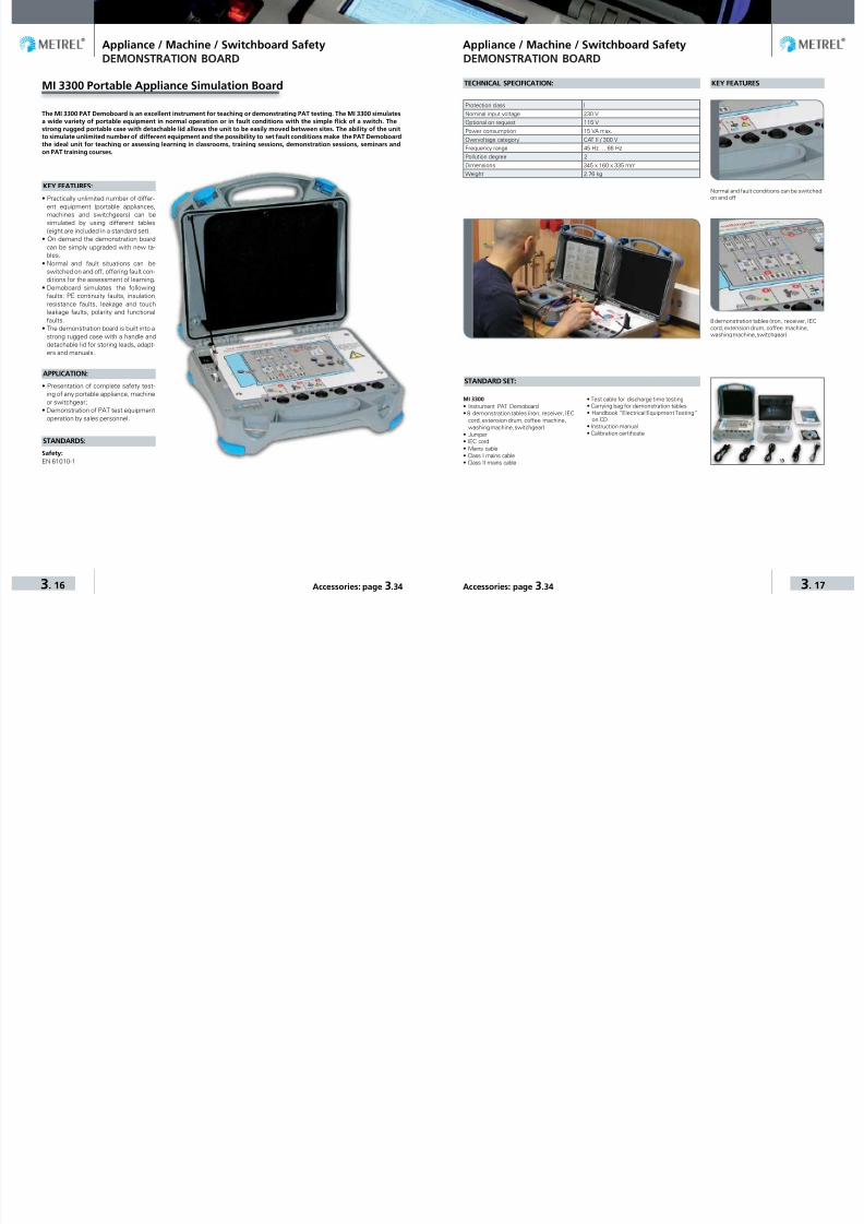
7/25/2019 METREL General Catalog Engl 2015
http://slidepdf.com/reader/full/metrel-general-catalog-engl-2015 64/121
Appliance / Machine / Switchboard Safety Appliance / Machine / Switchboard Safety
3. 16 3. 17Accessories: page 3.34 Accessories: page 3.34
MI 3300 Portable Appliance Simulation Board
KEY FEATURES:
• Practically unlimited number of differ-
ent equipment (portable appliances,machines and switchgears) can besimulated by using different tables(eight are included in a standard set).
• On demand the demonstration boardcan be simply upgraded with new ta-bles.
• Normal and fault situations can beswitched on and off, offering fault con-ditions for the assessment of learning.
• Demoboard simulates the followingfaults: PE continuity faults, insulationresistance faults, leakage and touchleakage faults, polarity and functionalfaults.
• The demonstration board is built into astrong rugged case with a handle anddetachable lid for storing leads, adapt-ers and manuals.
APPLICATION:
• Presentation of complete safety test-ing of any portable appliance, machineor switchgear;
• Demonstration of PAT test equipment
operation by sales personnel.
STANDARDS:
Safety:EN 61010-1
The MI 3300 PAT Demoboard is an excellent instrument for teaching or demonstrating PAT testing. The MI 3300 simulatesa wide variety of portable equipment in normal operation or in fault conditions with the simple flick of a switch. Thestrong rugged portable case with detachable lid allows the unit to be easily moved between sites. The ability of the unitto simulate unlimited number of different equipment and the possibility to set fault conditions make the PAT Demoboardthe ideal unit for teaching or assessing learning in classrooms, training sessions, demonstration sessions, seminars andon PAT training courses.
DEMONSTRATION BOARD
KEY FEATURESTECHNICAL SPECIFICATION:
STANDARD SET:
Protection class I
Nominal input voltage 230 V
Optional on request 115 V
Power consumption 15 VA max.
Overvoltage category CAT II / 300 V
Frequency range 45 Hz … 66 Hz
Pollution degree 2
Dimensions 345 x 160 x 335 mm
Weight 2.76 kg
8 demonstration tables (iron, receiver, IECcord, extension drum, coffee machine,washing machine, switchgear)
Normal and fault conditions can be switchedon and off.
MI 3300• Instrument PAT Demoboard• 8 demonstration tables (iron, receiver, IEC
cord ,extension drum, coffee machine,washing machine, switchgear)
• Jumper• IEC cord• Mains cable• Class I mains cable• Class II mains cable
• Test cable for discharge time testing• Carrying bag for demonstration tables• Handbook “Electrical Equipment Testing”
on CD• Instruction manual• Calibration certificate
DEMONSTRATION BOARD

7/25/2019 METREL General Catalog Engl 2015
http://slidepdf.com/reader/full/metrel-general-catalog-engl-2015 65/121

7/25/2019 METREL General Catalog Engl 2015
http://slidepdf.com/reader/full/metrel-general-catalog-engl-2015 66/121

7/25/2019 METREL General Catalog Engl 2015
http://slidepdf.com/reader/full/metrel-general-catalog-engl-2015 67/121
Appliance / Machine / Switchboard Safety Appliance / Machine / Switchboard Safety
3. 22 3. 23Accessories: page 3.34 Accessories: page 3.34
MI 3394 CE MultiTesterXA
MEASURING FUNCTIONS:
• High Voltage, programmed (AC/DC).• High Voltage burn-out test.• Continuity tests.• Insulation resistance measurement.• Substitute leakage current.• Differential leakage current.• Touch leakage current.• PE-leakage current.• Discharge time.• Functional test (power P/S/Q, volt-
age, current, cos ϕ, frequency, ThdU,ThdI,PF).
KEY FEATURES:
• Data management: the instrumentfeatures in unique user friendly datamanagement facility and state of theart memory organizer.
• Multiple test terminals: different testterminals enabling the user to chosefrom performing single tests or au-tosequences from single test socket.
• Auto testing: autosequences can becomposed via instruments intuitivesequence organizer.
• MicroSD: support for microSD
memory card (8-GB supplied with theinstrument) up to 32GB.
• Colour display: 3.4˝colour LCD dis-play with touch screen.
• Hi-pot: high voltage AC (5kV at500VA) and DC (6kV) test.
• Continuity: 4 – wire continuity testwith selectable test current (0.2 A, 4A, 10A, 25A) enabling precise meas-urements.
• Communication: 4 – RS232, USB,Ethernet and Bluetooth communica-tion ports enabling downloading,uploading and remote control overinstrument.
• Multi-system testing: the instrumentcan be used on TT, TN, IT and 115 Vsupply systems.
APPLICATION:
• Laboratories,• Automated production lines,• Specialized workshops.
STANDARDS:
Functionality:IEC 60335 Household and similarelectrical appliances61439 Low-voltage switchgear andcontrolgear assembliesIEC 60598 LuminairesIEC 60950 Safety of informationtechnology equipmentIEC 61010 Safety requirements for
The MI 3394 CE MultiTesterXA is a portable instrument intended for electrical safety testing and CE certification of electri-cal appliances, machines and switchboards during the production. The instrument features in strong data managementfacility enabling the user to create custom auto-tests with predefined limits for pass/fail evaluation, to import predefinedstructure including test sequences or complete projects from PC software, plus strong memory organizer. The PC softwareMES-Manager enables the upload of automated test s equences, projects, downloading of test results to the PC, automaticdata storage into a file, printing of test reports. Due to selected test functions, durable construct ion and accompanying PCSW package CE MultiTesterXA is the perfect instrument for electrical safety testing in the most demanding environmentslike laboratories, automated production lines or specialized workshops.
electrical equipmentVDE 0701-702 Inspection after repair,modification of electrical appliancesPeriodic inspection on electricalappliances General requirements forelectrical safetyEN 50191 Erection and operation ofelectrical test equipment
Safety:
EN 61010-1; EN 61010-2-030;EN 61010-031; EN 61557
Electromagnetic compatibility:EN 61326-1
TECHNICAL SPECIFICATION:
STANDARD SET:
MI 3394• Instrument CE MultiTesterXA• HV test pistol with 2 m cable, 2 pcs• Continuity test lead, 2.5 m, 2 pcs• Continuity test lead, red, 1.5 m, 1pcs• Insulation test lead, red, 2.5 m• Insulation test lead, black, 2.5 m• Crocodile clip, black, 3 pcs• Crocodile clip, red, 2 pcs• Discharge time cable
• Mains cable• Bag for accessories• Calibration certificate• RS232 cable• USB cable• CD with instruction manual (full version)• PC SW Metrel ES Manager
MACHINE AND SWITCHBOARD TESTERS MACHINE AND SWITCHBOARD TESTERS
Function Measuring range Resolution AccuracyHVAC, Programmable HVAC- Test voltage (AC)
- Test current apparent capacitiveresistive
0 ... 1999 V2.00 ... 5.99 kV0.0 ... 99.9 mA0.0 mA ... 99.9 mA-99.9 mA ... 99.9 mA
1 V10 V0.1 mA0.1 mA0.1 mA
± (3 % of reading)± (3 % of reading)± (3 % of reading + 3 digits)IndicativeIndicative
HVDC, Programmable HVDC- Test voltage (DC)
- Test current
0 ... 1999 V2.00 ... 6.99 kV0.01 ... 9.99 mA
1 V10 V0.01 mA
± (3 % of reading)± (3 % of reading)± (5 % of reading + 3 digits)
Discharging time- t- Up
0.0 ... 9.9 s0 ... 550 V
0.1 s1 V
± (5 % of reading + 3 digits)± (5 % of reading + 3 digits)
Continuity (0.2A, 4A, 10A, 25A)
- R
0.00 Ω ... 19.99 Ω20.0 Ω ... 99.9 Ω100.0 Ω ... 199.9Ω
200 Ω ... 999 Ω
0.01Ω0.1Ω0.1Ω
1 Ω
± (2 % of reading + 2 digits)± 3 % of reading± 5 % of reading
IndicativeInsulation resistance (250 V, 500 V, 1000 V), Insulation resistance - S (250 V, 500 V, 1000 V)
- Riso/Riso-s 0.00 MΩ ... 19.99 MΩ20.0 MΩ ... 199.9 MΩ
0.01 MΩ0.1 MΩ
± (3 % of reading + 2 digits)± 5 % of reading
- Output voltage 0 V ... 1200 V 1 V ±(3 % of reading + 2 digits)Insulation resistance (50 V, 100 V), Insulation resistance - S (50 V, 100 V)
- Riso/Riso-s 0.00 MΩΩ ... 19.99 MΩ20.0 MΩΩ ... 199.9 MΩ
0.01 MΩ0.1 MΩ
± (5 % of reading + 2 digits)± 20 % of reading
- Output voltage 0 V ... 1200 V 1 V ±(3 % of reading + 2 digits)(open circuit voltage <50 V a.c.)- Isub / Isub s 0.00 mA ... 19.99 mA 10 µA ± (5 % of reading + 3 digits)Differential Leakage current- Idiff 0.00 mA ... 19.99 mA 0.01 mA ± (3 % of reading + 5 digits)PE leakage current- Ipe 0.00 mA ... 19.99 mA 0.01 mA ± (3 % of reading + 3 digits)Touch leakage current- Itou 0.00 mA ... 19.99 mA 0.01 mA ± (3 % of reading + 3 digits)Power
- P 0 W ... 999 W1.00 kW ... 3.70 kW
1 W10 W
± (5 % of reading + 5 digits)± 5 % of reading
- S 0 VA ... 999 VA1.00 kVA ... 3.70 kVA
1 VA10 VA
± (5 % of reading + 5 digits)± 5 % of reading
- Q ±(0 ... 999) VAr±(1.00 ... 3.70) kVAr
1 VAr10 VAr ± (5 % of reading + 5 digits)
- PF 0.00i ... 1.00i0.00c ... 1.00c
0.010.01
± (5 % of reading + 5 digits)± (5 % of reading + 5 digits)
- THDU 0.0% ... 99.9% 0.1% ±(5 % of reading + 5 digits)- THDI 0.0% ... 99.9% 0.1% ±(5 % of reading + 5 digits)
- Cos ϕ0.00i ... 1.00i0.00c ... 1.00c
0.010.01
±(5 % of reading + 5 digits)±(5 % of reading + 5 digits)
- U 0.1 V ... 199.9 V200 V ... 264 V
0.11 V
±(3 % of reading + 10 digits)±(3 % of reading)
- I 0.00 A ... 16.00 A 0.01 ±(3 % of reading + 5 digits)Power supply 110 V / 230 V AC, 50 Hz / 60 HzOverv ol ta ge ca tegory CAT II / 300 V, CAT II / 600 V ( DI SCH1 / DI SCH2, onl y)Protection class IHV output 5 kV a.c. / 6 kV d.c., double insulationCOM port 4 x RS232, 1 x USB, 1 x Ethernet, 1 x BluetoothDimensions (w×h×d): 43,5 cm x 29,2 cm x 15,5 cmWeight: 17 kg

7/25/2019 METREL General Catalog Engl 2015
http://slidepdf.com/reader/full/metrel-general-catalog-engl-2015 68/121
Appliance / Machine / Switchboard Safety Appliance / Machine / Switchboard Safety
3. 24 3. 25Accessories: page 3.34 Accessories: page 3.34
MI 2094 CE MultiTester
MEASURING FUNCTIONS:
• Withstanding programmed voltage;• Withstanding voltage test;
• High voltage burn-out test;• Continuity tests;• Insulation resistance measurement;• Substitute leakage current;• Differential leakage current;• Touch leakage current;• Discharge time;• Functional test (power, voltage, cur-
rent, cos ϕ, frequency).
KEY FEATURES:
• Auto testing: up to 10 autosequenceseach composed of up to 50 steps, in-cluding pauses and comments, can becreated via the optional CE Link soft-ware and saved in the memory of theinstrument.
• Withstanding voltage test: testingof insulation with programmable testvoltage up to 5 kV.
• Burn test: instrument performs in-sulation breakdown test with limitedbreakdown current.
• Continuity testing: wide selection of test
currents (100 mA, 200 mA, 10 A, 25 A).
• Easy to use: rotary switch makes theselection of a single test simple andeasy while the programmable autose-quence testing prevent the risk ofmissing a test.
• Portable: due to lightweight designand rugged carrying case with handleCE MultiTester can be moved betweenlocations.
• Safe: high quality accessories and op-tional safety devices like remote con-trol pedal and warning lamp ensure themost safe performance of the meas-urements.
• Rack mount: due to the autotest facil-ity and EXT / DOOR remote control ofthe instrument CE MultiTester can beintegrated into the automated produc-tion line for output check of manufac-tured products.
• Multi-system testing: the instrumentcan be used on TT, TN, IT and 115 Vsupply systems.
• Downloadable: the optional PC SW CE
Link enables the upload of test sequenc-
es, downloading of test results directly
to the PC, automatic data storage into a
file and printing of test reports.
APPLICATION:
• Portable appliances, switchgears, ma-chines safety testing;
• Testing and verifying of manufacturedproducts according to European Safetylegislation;
The MI 2094 CE MultiTester is intended for electrical safety testing and CE certification of electrical appliances, machinesand switchboards during the production. It is suitable for testing the appliances after repairs and maintenance work aswell. With the ability to test a multitude of different appliances the MI 2094 still remains portable, safe and easy to use.The optional PC software CE Link enables the upload of automated test sequences, downloading of test results directlyto the PC, automatic data storage into a file and printing of test reports. Due to selected test functions, durable construc-tion and accompanying PC SW package CE MultiTester is the perfect instrument for electrical safety testing in the mostdemanding environments like laboratories, automated production lines or specialized workshops.
• Testing of electrical appliances after re-pairs and maintenance work.
STANDARDS:
Functionality:EN 61557; EN 60204-1; EN 60335-1;EN 60439-1; EN 60598-1; IEC 60745;IEC 60755; EN 61010-1; IEC 60950;IEC 61029; IEC 61558-1; EN 60065;VDE 701 T1; VDE 702 T1
Safety: IEC 61010-1
Electromagnetic compatibility:EN 61326
MACHINE AND SWITCHBOARD TESTERS
TECHNICAL SPECIFICATION:
STANDARD SET:
Function Measuring range Resolution Accuracy
Withstanding test (PROG.HV and HV)
- Test voltage (AC)0.100 kV … 0.999 kV1.000 kV … 5.000 kV
0.001 kV0.001 kV
±(2 % of reading + 5 digits)±(3 % of reading + 5 digits)
- Test current 0.0 mA … 500.0 mA 0.1 mA ±(5 % of reading + 5 digits)
PE continuity
- Test current 10 A and 25 A0.000 Ω … 0.999 Ω
1.000 Ω … 2.000 Ω
2.001 Ω … 9.999 Ω
0.001 Ω
0.001 Ω
0.001 Ω
±(3 % of reading + 3 digits)±(3 % of reading + 10 digits)Indicator only
- Test current 100 mA0.00 Ω … 9.99 Ω10.0 Ω … 100.0 Ω
0.01 Ω0.1 Ω
±(5 % of reading + 12 digits)±(5 % of reading + 6 digits)
- Test current 200 mA0.00 Ω … 9.99 Ω
10.0 Ω … 100.0 Ω0.01 Ω
0.1 Ω±(5 % of reading + 6 digits)±(5 % of reading + 6 digits)
Insulation resistance 0.000 MΩ … 1.999 MΩ2.000 MΩ … 199.9 MΩ200 MΩ … 999 MΩ
0.001 MΩ0.001 MΩ, 0.01 MΩ, 0.1 MΩ1 MΩ
±(5 % of reading + 10 digits)±(3 % of reading + 3 digits)±(10 % of reading + 10 digits)
Differential leakage current0.00 mA … 3.99 mA4.0 mA … 20.0 mA
0.01 mA0.1 mA
±(5 % of reading + 3 digits)±(5 % of reading + 3 digits)
Substitute leakage current 0.00 mA … 20.00 mA 0.01 mA ±(5 % of reading + 3 digits)
Touch leakage current 0.00 mA … 2.00 mA 0.01 mA ±(5 % of reading + 3 digits)
Functional test
- Active and apparent power (W or VA)0.0 … 199.9200 … 3500
0.11
±(5 % of reading + 10 digits)±(5 % of reading + 3 digits)
- Voltage 0 V … 400 V 1 V ±(2 % of reading + 2 digits)
- Test current0.000 A … 0.999 A1.00 A … 15.99 A
0.001 A0.01 A
±(3 % of reading + 5 digits)±(5 % of reading + 5 digits)
- cos ϕ 0.00 … 1.00 0.01 ±(3 % of reading + 3 digits)
- Frequency 45.00 Hz … 65.00 Hz 0.01 Hz ±(0.1 % of reading + 3 digits)
Discharge time 0 s … 10 s 0.1 s ±(2 % of reading + 0.2 s)
Power supply 115 V / 230 V, 50 Hz / 60 Hz
Overvolt age category CAT III / 300 V; CAT II / 600 V
Protection class I
COM port RS232 and USB
Dimensions 410 x 175 × 370 mm
Weight 13.5 kg
MI 2094• Instrument CE MultiTester• HV test pistol with 2 m cable, 2 pcs• Continuity test lead, 2.5 m, 2 pcs• Insulation test lead, red, 2.5 m• Insulation test lead, black, 2.5 m• Crocodile clip, black, 3 pcs• Crocodile clip, red, 2 pcs• Discharge time cable• Mains cable
• Bag for accesories• Instruction manual• Calibration certificate
MACHINE AND SWITCHBOARD TESTERS

7/25/2019 METREL General Catalog Engl 2015
http://slidepdf.com/reader/full/metrel-general-catalog-engl-2015 69/121
Appliance / Machine / Switchboard Safety Appliance / Machine / Switchboard Safety
3. 26 3. 27Accessories: page 3.34 Accessories: page 3.34
MI 3321 MultiServicerXA
MEASURING FUNCTIONS:
• Continuity tests (200 mA, 10 A);• Insulation resistance;• Withstanding voltage tests (1000 V,
1890 V, 2500 V);• Substitute leakage current;• Differential leakage current;• Touch leakage current;• IEC cord polarity test;• Leakage and load TRMS current meas-
urement with current clamp;• Portable RCD testing;• RCD testing;• Line and loop impedance;• High resolution line / loop impedance (mΩ).• Discharge time;• Three phase voltage / rotary field;• Functional test.
KEY FEATURES:
• 3 in 1: instrument performs testing ofportable appliances (acc. to VDE 07010702), machines (acc. to IEC/EN 60204Ed.5) and switchgears (acc. to IEC/ EN60439 and the new IEC 61439) includingfunctional and leakage tests for DUTswith nominal power up to 3.5 kW.
• Multi-tasking: up to 18 different meas-urements can be performed either asa single test or pre-programmed testsequences (PAT mode).
• Automated: automatic testing andPASS / FAIL evaluation of test results
according to appropriate standard.• Project uploading: previous test datacan be uploaded for fast retesting ofthe object.
• Scan and test: optional barcoding sys-tem and PASS / FAIL barcode label print-ing make retesting quick and simple.
• RFID: support for advanced RFID iden-tification system.
• User friendly: large LCD screen, fullQWERTY keyboard, help screens andwarnings make the instrument an ex-tremely easy to use.
• Fixed appliance tests: ports, leads andoptional accessories fully support thetesting of fixed machines and applianc-es while normal socket supports plug-in machines and appliances testing.
• RCD testing: instrument enables test-ing of parameters of RCDs and port-able RCDs.
• Clamp leakage current measurement:quick measurement of leakage currentwith current clamps directly on powersupply cable without disconnection ofappliance from mains.
• Discharge time test: testing of howlong it takes for the machine dischargeafter power is removed.
• Withstanding voltage test: instru-ment performs 2500 VAC, 1890 VAC and1000 VAC withstanding voltage testswith settable current limit.
• Trend functionality: test results canbe uploaded from PC to the instrumentfor comparison between old and newtest results on site.
• Downloadable: up to 6000 test re-sults with measuring parameters canbe stored in two level memory anddownloaded to the PC with the help ofPC SW PATLink PRO.
• PC SW PATLink PRO included in thestandard set enables downloading, view-ing, printing of test results and exportingof data to spreadsheet applications .
• PC SW PATLink PRO Plus enables ad-
Multifunctional portable test instrument MI 3321 MultiServicerXA is intended to perform all necessary measurements fortesting the electrical safety of portable electrical equipment, machines and switchgears. It is the first machine tester cover-ing all necessary tests according to new IEC/EN 60204 ed.5 including Loop impedance, RCD and HV tests. MultiServicerXAenables measurement of discharge time, power and current consumption and resistance to excessive voltages which arethe main parameters in the safety testing of hard wired appliances and large machinery. With an easy to use user interface,large graphic LCD, QWERTY keyboard, help menus with connection diagrams and extra ports for testing fixed installationsthe MI 3321 is the best solution for safety testing.
vanced analysis of test results, uploadof structures and data upload to theinstrument for on site comparison ofold and new results, upload of pre-pro-grammed custom autosequences and
creation of professional test reports.
APPLICATION:
• Factory machinery safety testing;• Industrial safety testing;• Portable appliances safety testing;• Switchgear safety testing.
STANDARDS:
Functionality: IEC/EN 61557; IEC 60439-1; EN 60204; IEC/EN 60204-1 Ed.5;IEC/EN 60439; IEC 60755; IEC 60598-1;VDE 0404; VDE 0701-0702Electromagnetic compatibility:EN 61326Safety: EN 61010-1; EN 61010-031
MACHINE AND SWITCHBOARD TESTERS
TECHNICAL SPECIFICATION:
Function Measuring range Resolution AccuracyWithstanding test with 1890 VAC and 2500 VAC:- Test voltage 0 V … 3000 V 1 V ±(5 % of reading + 5 digits)- Current 0.0 mA … 99.9 mA 0.1 mA ±(10 % of reading + 8 digits)Withstanding test with 1000 VAC:- Test voltage 0 V … 1500 V 1 V ±(5 % of reading + 5 digits)
- Current 0.0 mA … 199.9 mA200 mA … 500 mA
0.1 mA1 mA
±(5 % of reading + 5 digits)±(5 % of reading + 5 digits)
Insulation resistance with 250 VDC; 500 VDC
0.000 MΩ … 0.500 MΩ0.501 MΩ … 1.999 MΩ2.00 MΩ … 19.99 MΩ20.0 MΩ … 199.9 MΩ
0.001 MΩ0.001 MΩ0.01 MΩ0.1 MΩ
±(10 % of reading + 5 digits)±(5 % of reading + 3 digits)±(5 % of reading + 3 digits)±(5 % of reading + 3 digits)
Insulation - S resistance with 250 V DC; 500 VDC
0.000 MΩ … 0.500 MΩ0.501 MΩ … 1.999 MΩ2.00 MΩ … 19.99 MΩ
0.001 MΩ0.001 MΩ0.01 MΩ
±(10 % of reading + 5 digits)±(5 % of reading + 3 digits)±(5 % of reading + 3 digits)
PE continuity with 10 A (PAT) 0.00 Ω … 1.99 Ω 0.01 Ω ±(5 % of reading + 3 digits)
PE continuity with 10 A (other) 0.000 Ω … 0.999 Ω1.00 Ω … 1.99 Ω
0.001 Ω0.01 Ω
±(5 % of reading + 6 digits)±(5 % of reading + 3 digits)
PE continuity with 200 mA 0.00 Ω … 1.99 Ω 0.01 Ω ±(5 % of reading + 3 digits)Discharge time 0.0 s … 9.9 s 0.1 s ±(5 % of reading + 3 digits)D if fer en ti al l eakag e cu rr ent 0 .00 mA … 9 .9 9 mA 0 .01 mA ±(5 % o f r ea di ng + 5 d igi ts)Substitute leakage current 0.00 mA … 19.99 mA 0.01 mA ±(5 % of reading + 5 digits)Touch leakage current 0.00 mA … 2.50 mA 0.01 mA ±(10 % of reading + 5 digits)Functional test 0.00 kVA … 4.00 kVA 0.01 kVA ±(5 % of reading + 3 digits)
TRMS current with clamp
0.00 mA … 9.99 mA10.0 mA … 99.9 mA100 mA … 999 mA1.00 A … 9.99 A10.0 A … 24.9 A
0.01 mA0.1 mA1 mA0.01 A0.1 A
±(5 % of reading + 10 digits)±(5 % of reading + 5 digits)±(5 % of reading + 5 digits)±(5 % of reading + 5 digits)±(5 % of reading + 5 digits)
PRCD testing I∆N: 10, 15, 30 mA
- Trip-out time0 ms … 300 ms (1/2xI∆N)0 ms … 300 ms (I∆N)0 ms … 40 ms (5xI∆N)
1 ms1 ms1 ms
±3 ms±3 ms±3 ms
RCD testing I∆N: 10, 30, 100, 300, 500, 1000 mA
- Contact voltage 0.0 V … 19.9 V20.0 V … 99.9 V
0.1 V0.1 V
(-0 %/+15 %) of reading ±10 dig.(-0 %/+15 %) of reading
- Trip-out time 0.0 ms … 40.0 ms0.0 ms … 300.0 ms
0.1 ms0.1 ms
±1 ms±3 ms
- Trip-out current0.2×I∆N … 1.1×I∆N (AC type)0.2×I∆N … 1.5×I∆N (A type, I∆N ≥30 mA)0.2×I∆N … 2.2×I∆N (A type, I∆N <30 mA)
0.05×I∆N
0.05×I∆N
0.05×I∆N
±0.1×I∆N
±0.1×I∆N
±0.1×I∆N
Fault loop impedance / Line impedance0.00 Ω … 9.99 Ω10.0 Ω … 99.9 Ω100 Ω … 1999 Ω
0.01 Ω0.1 Ω1 Ω
±(5 % of reading + 5 digits)±(5 % of reading + 5 digits)±10 % of reading
Voltage 0 V … 550 V 1 V ±(2 % of reading + 2 digits)Frequency 14.0 Hz … 499.9 Hz 0.1 Hz ±(0.2 % of reading + 1 digit)Power supply 115 V / 230 V, 50 Hz / 60 Hz
Overvoltag e category CAT II / 300 VProtection class ICOM port RS232 and USBDimensions 345 x 160 x 335 mmWeight 8.4 kg
STANDARD SET:
MI 3321• Instrument MultiServicerXA• HV test lead• Plug test cable• 3-wire test lead• Test lead, black, 1.5 m• Test lead, red, 1.5 m• Test lead, red, 4 m• Test lead, green, 1.5 m• Test probe, 4 pcs (black, red. green, blue)
• Crocodile clip, black, 3 pcs• Protective bag for accessories• PC SW PATLink PRO with RS232 and USB
cable• Instruction manual• Calibration certificate
MACHINE AND SWITCHBOARD TESTERS

7/25/2019 METREL General Catalog Engl 2015
http://slidepdf.com/reader/full/metrel-general-catalog-engl-2015 70/121
Appliance / Machine / Switchboard Safety Appliance / Machine / Switchboard Safety
3. 28 3. 29Accessories: page 3.34 Accessories: page 3.34
MEASURING FUNCTIONS:
• Insulation resistance;
• Withstanding voltage tests (1000 V,2500 V);
• Continuity tests (200 mA, 10 A);• Voltage drop;• Substitute leakage current;• Differential leakage current;• Touch leakage current;• Discharge time;• Functional test.
KEY FEATURES:
• 3 in 1: instrument performs testingof portable appliances, machines andswitchgears including functional andleakage tests for DUTs with nominalpower up to 3.5 kW.
• Easy to use: instrument connectionguide on lid and rotating function se-lector make the MI 2170 an extremelyeasy to use.
• PASS / FAIL: configurable limits enableevaluation of test results according toappropriate standard.
• Fixed appliance tests: ports, leadsand optional accessories fully supportthe testing of fixed machines and ap-pliances while normal socket supportsplug-in machines and appliances test-ing.
• Discharge time test: testing of howlong it takes for the machine dischargeafter power is removed.
• Withstanding voltage test: instru-ment performs 2500 VAC and 1000 VAC
withstanding voltage tests with setta-ble current limit.
• Downloadable: test results can bestored in two level memory structure.
• PC SW PATLink PRO included in thestandard set enables downloading,viewing, printing of test results andexporting of data to spreadsheet ap-plications.
• PC SW PATLink PRO Plus enablesadvanced analysis of test results andcreation of professional test reports.
APPLICATION:
• Factory machinery safety testing;• Industrial safety testing;• Portable appliances safety testing;• Switchgear safety testing.
The MI 2170 MultiServicer is a multifunctional portable test instrument intended for performing all necessary measure-ments for testing the electrical safety of machines, switchgears and portable electrical appliances. Apart from insulationresistance, leakage currents and continuity measurements, MultiServicer enables measurement of discharge time, currentconsumption and resistance to excessive voltages which are the main parameters in the safety testing of hard wired ap-pliances and large machinery. MultiServicer is placed into robust waterproof case for use in harsh industrial environments.Quick reference guide for testing, large LCD screen, user friendly interface and rotary function selector make the safetytesting with MultiServicer quick and simple.
STANDARDS:
Functionality:IEC 60204; IEC 60439-1; VDE 701;VDE 702; IEC 60598-1; IEC 60755;IEC 50144-1Electromagnetic compatibility:EN 50081-1;EN 61000-6-1Safety:EN 61010-1
MI 2170 MultiServicer
MACHINE AND SWITCHBOARD TESTERS
STANDARD SET:
MI 2170• Instrument MultiServicer• HV test lead• Test lead, black, 2 m• Test lead, red, 2 m• Test probe, black• Test probe, red• Crocodile clip, black• Crocodile clip, red• PC SW PATLink PRO with RS232 cable
• Protective bag for accessories• Instruction manual• Calibration certificate
Function Measuring range Resolution Accuracy
Withstanding test with 2500 VAC:
- Test voltage 0.00 kV … 3.00 kV 0.01 kV ±(5 % of reading + 5 digits)
- Current 0.0 mA … 99.9 mA 0.1 mA ±(5 % of reading + 5 digits)
Withstanding test with 1000 VAC:
- Test voltage 0.00 kV … 1.50 kV 0.01 kV ±(5 % of reading + 5 digits)
- Current0.0 mA … 109.9 mA110 mA … 500 mA
0.1 mA1 mA
±(5 % of reading + 5 digits)±(5 % of reading + 5 digits)
Insulation resistance measurement with 500 VDC 0.00 MΩ … 19.99 MΩ 0.01 MΩ ±(5 % of reading + 5 digits)
Voltage drop 0.00 V … 11.99 V 0.01 V ±(5 % of reading + 5 digits)
PE continuity with 200 mA 0.00 Ω … 19.99 Ω 0.01 Ω ±(5 % of reading + 5 digits)
PE continuity with 10 A 0.000 Ω … 1.999 Ω 0.001 Ω ±(5 % of reading + 5 digits)
PE continuity with 200 mA 0.00 Ω … 19.99 Ω 0.01 Ω ±(5 % of reading + 5 digits)
Discharge time 0.0 s … 9.9 s 0.1 s ±(5 % of reading + 3 digits)
Dif fe rent ia l l ea ka ge c ur rent 0 .00 mA … 19. 99 mA 0.01 mA ± (5 % of rea ding + 5 d ig its)
Subst itute l ea ka ge c ur rent 0 .00 mA … 19. 99 mA 0.01 mA ± (5 % of rea ding + 5 d ig its)
To uch l eakag e cu rr en t 0 .00 mA … 1 .9 9 mA 0 .0 1 mA ±(5 % o f r ead in g + 5 d ig it s)
Functional test; current 0.00 A … 15.99 A 0.01 A ±(5 % of reading + 3 digits)
Power supply 230 V, 50 Hz
Overvoltage category CAT III / 300 V
Protection class I
COM port RS232
Dimensions 345 x 160 x 335 mm
Weight 9.5 kg
MACHINE AND SWITCHBOARD TESTERS
TECHNICAL SPECIFICATION:

7/25/2019 METREL General Catalog Engl 2015
http://slidepdf.com/reader/full/metrel-general-catalog-engl-2015 71/121

7/25/2019 METREL General Catalog Engl 2015
http://slidepdf.com/reader/full/metrel-general-catalog-engl-2015 72/121
Appliance / Machine / Switchboard Safety Appliance / Machine / Switchboard Safety
3. 32 3. 33Accessories: page 3.34 Accessories: page 3.34
A 1433 PATLink Android
The PATLink Android is a powerful tool. It enables fast and simple data management of tested appliances, as well as aquick overview of already performed tests by simply scanning a QR code. The Application enables the user to enter andsave data to the test instrument by using a Smart phones’ keyboard. Also it enables a creation of the custom made data-base for portable appliances’ ID’s, the appliances’s names and the appliances’ locations. All these features enable the usera faster and easier data handling.
PATLink Android enables the user toscan the QR codes which contain in-formation of the previous results, thetest status, and the previously usedtest sequence. Based on this informa-
tion the user can start the retest of theappliance with a single press on theAndroid Application.
KEY FEATURES:
• On - site comparrison of the test re-sults;
• Creation of the custom database;• Use of Smart phones camera for the
QR and Barcode scanning;• Use of Smart Phones virtual keyboard.
ADDITIONAL FEATURES:
• In Built Risk Assessment tool to pro-vide correct Re-Test periods in accord-ance with COP version 4;
• Protect your business by applying QRcodes instead of Bar Codes.
PATLink Android is compatible with:• MI 3309 BT DeltaPAT• MI 3310 25A SigmaPAT (HW3)• MI 3311 GammaPAT
(supported by BT dongle) READY
Supported byBT dongle
Built-in BTsolution
PC SOFTWARE
A 1434 aPATLink Android
The aPATLink Android is Advanced Portable Appliance Testing tool. It enables fast and simple data management of testedappliances, as well as a quick overview of already performed tests by simply scanning a QR code. The Application enablesthe user to send results to the main office before leaving test site, enter and save data to the test instrument by using aSmart phones’ keyboard. Also it enables a creation of the custom made database for portable appliances’ ID’s, the appli-ances’s names and the appliances’ locations. All these features enable the user a faster and easier data handling.
KEY FEATURES:
• Complete database of tested applianc-
es on one location;
• Upcoming retest warning on your
smart phone or tablet;• Simple, custom auto-test creation (MI
3309 DeltaPAT);
• Use of smart phones barcode or QR
code scanner for quicker data entry;
• Remote control of PAT tester;
• Easy data entering;
• Projects can be stored to your drop
box account;
• Sending data to main office, before
leaving test site;
• Built in risk assessment calculator;
• None skilled user can perform test
simply by scanning the QR code con-
taining all needed information for spe-
cific appliance;
• Overview of testing parameters by
simple scanning QR code.
ADDITIONAL FEATURES:
• In Built Risk Assessment tool to pro-
vide correct Re-Test periods in accord-
ance with COP version 4;• Protect your business by applying QR
codes instead of Bar Codes.
aPATLink Android is compatible with:
• MI 3309 BT DeltaPAT
• MI 3310 SigmaPAT (HW3)
• MI 3310 25A SigmaPAT (HW3)
READY
Supported byBT dongle
Built-in BTsolution
PC SOFTWARE

7/25/2019 METREL General Catalog Engl 2015
http://slidepdf.com/reader/full/metrel-general-catalog-engl-2015 73/121

7/25/2019 METREL General Catalog Engl 2015
http://slidepdf.com/reader/full/metrel-general-catalog-engl-2015 74/121
Appliance / Machine / Switchboard Safety Appliance / Machine / Switchboard Safety
3. 36 3. 37Accessories: page 3.34 Accessories: page 3.34
PhotoPart
numberDescription Target application
M I 3 3 0 5
M I 3 3 0 4
M I 3 3 1 0 2 5 A
M I 3 3 1 0
M I 3 3 0 9 B T
M I 3 3 1 1
A 1 3 2 2
A 1 4 2 2
M I 3 3 9 4
M I 2 0 9 4
M I 3 3 2 1
M I 2 1 7 0
A 1059Insulation and Conti-nuity adapter
1-phase 16 A CEE plug adapter for insulation re-sistance and continuity measurements.
– – – – – – – – – – –
A 1079 Discharge time cableAdaptor for measuring discharge time on internalelectronic components.
– – – – – – – – – – –
A 1060Power splitter fordischarge time meas-urement
T-type power splitter for measurements of dis-charge time on machinery and switchgear.
– – – – – – – –
S 1057HV test lead, 5 m,2 pcs
High voltage extension test leads for measure-ments on larger electrical equipment.
– – – – – – – – – – –
S 1058Continuity test lead, 2x 10 m, 2 pcs
Extension test leads for continuity measure-ments.
– – – – – – – – – –
S 1072Continuity test leadwith crocodile clip, 2 x2.5 m, 2 pcs
Extension test leads with protection shield andwith crocodile clips for continuity testing with high
test currents (10 A, 25 A).– – – – – – – – – –
S 2012Continuity test lead,10 m, 2 pcs (red,black)
2 pieces of extension test lead for continuitymeasurements.
– – – – – – – – –
S 2025Test lead, 1.5 m, 2pcs (black, red)
Co nn ect ion le ad s f or d if fe re nt me asu re me nt s. – – – – – – – – –
A 1095Insulation / Subleak-age adapter
The adapter equipped with CEE 16 A schuko plugsupports insulation resistance and touch leakagecurrent measurements on Class 1 portable appli-ances with conductive metal parts.
– – – – – – – – – – –
A 1096Adapter for perma-nently wired loads
The adapter allows continuity and insulation re-sistance measurement on permanently wiredloads (without plug).
– – – – – – – – – – –
A 1447PRCD Extensionadapter
Adapter for testing of PRCD-S/K, supported fromHW4.
– – – – – – – – – – –
A 1153 Test lead, black, 20 mExtension test lead for earth and continuitymeasurements.
–
Selection Guide for PAT Accessories
Option – Not available
Selection Guide for PAT Accessories
PhotoPart
numberDescription Target application
M I 3 3 0 5
M I 3 3 0 4
M I 3 3 1 0 2 5 A
M I 3 3 1 0
M I 3 3 0 9 B T
M I 3 3 1 1
A 1 3 2 2
A 1 4 2 2
M I 3 3 9 4
M I 2 0 9 4
M I 3 3 2 1
M I 2 1 7 0
A 1154 Test lead, black, 4 mExtension test lead for earth and continuitymeasurements.
–
A 1331Test lead withcrocodile clip,black, 1,5 m
Test lead with crocodile cl ip for PAT testing. – – – – – – –
A 1404Test lead with test tip,black, 1,5 m
Earth bond test lead with test tip for PAT testing. – – – – – – – – – –
A 1334 IEC cable, 2 mAdditional IEC cable for performing PRCD testwith MI 3309.
– – – – – – – –
A 1341 Test lead, green 1.5 m Test lead for PAT safety testing. – – – – – –
A 1342Test lead, brown1.5 m
Test lead for PAT safety testing. – – – – – – – – –
A 1309 Crocodile clip, greenCrocodile clip assures secure and permanentcontact during the measurement on bus bars,fixing screws, etc.
– – – – – –
A 1310 Crocodile clip, blueCrocodile clip assures secure and permanentcontact during the measurement on bus bars,fixing screws, etc.
– – – – – – – – – – –
A 1297 Crocodile clip, brownCrocodile clip assures secure and permanentcontact during the measurement on bus bars,fixing screws, etc.
– – – – – – – – –
A 1013 Crocodile clip, blackCrocodile clip assures secure and permanentcontact during the measurement on bus bars,fixing screws, etc.
– – –
A 1064 Crocodile clip, redCrocodile clip assures secure and permanentcontact during the measurement on bus bars,fixing screws, etc.
– – – – – – – – –
A 1062 Test probe, green
Test probe with ∅ 4 mm connection is suitablefor performing measurements both in mains out-lets and in situations when no schuko outlet ispresent.
– – – – – –
Option – Not available

7/25/2019 METREL General Catalog Engl 2015
http://slidepdf.com/reader/full/metrel-general-catalog-engl-2015 75/121
Appliance / Machine / Switchboard Safety Appliance / Machine / Switchboard Safety
3. 38 3. 39Accessories: page 3.34 Accessories: page 3.34
Selection Guide for PAT Accessories
PhotoPart
numberDescription Target application
M I 3 3 0 5
M I 3 3 0 4
M I 3 3 1 0 2 5 A
M I 3 3 1 0
M I 3 3 0 9 B T
M I 3 3 1 1
A 1 3 2 2
A 1 4 2 2
M I 3 3 9 4
M I 2 0 9 4
M I 3 3 2 1
M I 2 1 7 0
A 1015 Test probe, blue
Test probe with ∅ 4 mm connection is suitablefor performing measurements both in mains out-lets and in situations when no schuko outlet ispresent.
– – – – – – – – – – –
A 1298 Test probe, brown
Test probe with ∅ 4 mm connection is suitablefor performing measurements both in mains out-lets and in situations when no schuko outlet ispresent.
– – – – – – – – –
A 1014 Test probe, black
Test probe with ∅ 4 mm connection is suitablefor performing measurements both in mains out-lets and in situations when no schuko outlet ispresent.
– –
A 1016 Test probe, red
Test probe with ∅ 4 mm connection is suitablefor performing measurements both in mains out-lets and in situations when no schuko outlet ispresent.
– – – – – – – – –
A 1268Test probe, brushtype, 4 mm
Test probe, brush type, assures good galvaniccontact when measuring on revolving parts,flat surfaces, screw connections and similar.Equipped with standard 4 mm connector.
– – –
A 1276Label printer with powerand data cables
Printer supports printing of identification labelscontaining a complete appliance information andPASS or FAIL evaluation of t est results.
– – – – –
A 1488 Able printerPrinter supports printing of QR codes which con-tain information of the previous results, the teststatus, and the previously used test sequence.
– – – – – – – – –
S 2062 BT lable printer setPrinter supports printing of QR codes which con-tain information of the previous results, the teststatus, and the previously used test sequence.
– – – – – – – –
A 1295 Spare label rollSpare label rolls for printer A 1276, (250 labelsper role)
– – – – –
A 1328 Hi-Q DT labelsHigh quality spare label rolls for printer A 1276,(250 labels per role)
– – – – –
A 1379Paper for A 1276,printer
Spare thermal receipt paper for printer A 1276. – – – – –
A 1450Spare label role forS 2062
Spare thermal receipt paper for printer S 2062,(250 labels per role).
– – – – – – – –
Option – Not available
Selection Guide for PAT Accessories
PhotoPart
numberDescription Target application
M I 3 3 0 5
M I 3 3 0 4
M I 3 3 1 0 2 5 A
M I 3 3 1 0
M I 3 3 0 9 B T
M I 3 3 1 1
A 1 3 2 2
A 1 4 2 2
M I 3 3 9 4
M I 2 0 9 4
M I 3 3 2 1
M I 2 1 7 0
A 1499Labels for ABLE andZEBRA RW22
Spare label rolls for printer A 1488, (250 labelsper role)
– – – – – – – – –
A 1359Thermal printer clean-ing kit
Cleaning Kit for printers A 1276 which includes25 Cleaning Cards and 25 Adhesive Removers.
– – – – –
A 1061 Barcode scannerBarcode scanner for identification of barcodela-belled appliances (for MI 2094 HW1 and HW2).
– – – – – – – – – – –
A 1105 Barcode scannerBarcode scanner for identification of barcodela-belled appliances.
– – –
A 1321Barcode scanner(Bluetooth)
Barcode scanner for identification of barcodela-belled appliances.
– – – – – – – – – – –
A 1106Barcode labels, 1000pcs
Appliances can be marked with barcode labelsfor easier identification.
– – – –
A 1107 RFID reader / writerRFID reader / writer allows to read and uploadtest results and informaton about tested electri-cal equipment to the RFID tags.
– – – – –
A 1108
RFID tags, self stick,25 pcsRFID tags, key tag,25 pcs
RFID tags sufficient memory space to store testresults and tested appliance information.
– – – – –
A 1337RFID tags, self-stich50 pcs
RFID tags have sufficient memory space to storetest results and tested appliance information.
– – – – –
A 1160Fast charger for 8 AAbatteries with a set of6 NiMH bat., type AA
Fast battery charger for up to 8 pieces of AA re-chargeable batteries, and a set of 6 pcs NiMHrechargeable batteries, type AA.
– – – – – – – – – –
A 1169Fast charger for AA,C, D and 9 V blockbatteries
Fast battery charger for up to 12 pcs AA, 6 pcsC or D rechargeable batteries, 4 pcs 9 V blockbatteries.
– – – – – – – –
A 1017Communication cableRS232
RS232 interface cable for connecting the instru-ment with the PC.
– – – –
Option – Not available

7/25/2019 METREL General Catalog Engl 2015
http://slidepdf.com/reader/full/metrel-general-catalog-engl-2015 76/121

7/25/2019 METREL General Catalog Engl 2015
http://slidepdf.com/reader/full/metrel-general-catalog-engl-2015 77/121
Power Quality Analysis Power Quality Analysis
4. 2 4. 3Accessories: page 4.24 Accessories: page 4.24
Power Quality Testing Power Quality Testing
GOOD TO KNOW GOOD TO KNOW
Find out more about modern powerquality measurement techniquesThere are quite a few reasons for meas-uring and analysing power quality nowa-days. Potential interactions betweenend use equipment and electric distribu-tion system, external electromagneticinterferences, resonant states betweenelectrical circuits and some other factorscall for a need to be analysed in orderthat harmful consequences can be omit-ted or prevented.
Power quality analysing includes meas-urements of:• Phase to ground voltages;• Phase to neutral voltages;• Neutral to ground voltages;• Phase to phase voltages in three-
phase systems;• Phase currents;• Current in a neutral conductor;• Frequency;• Power Factor, cos ϕ;• Harmonic components of current and
voltage and their direction;• Waveform of current and voltage at
specific circumstances (peak magni-tude, primary frequency, time of oc-currence, rising rate);
• Transients.
Active Power (P)Active power is the power generated if avoltage is placed over a purely resistiveload and current is allowed to flow. Ac-tive power is usually measured in watts(W) or kilowatts (kW).
Reactive Power (Q)
Reactive power is the power that isgenerated by reactive components (e.g.inductors, capacitors) to create a mag-netic field. This is usually measured inVolt-Ampers reactive (VAr).
Apparent Power (S)Apparent power is the perceived powerfrom a load that has both resistive andreactive components. Apparent poweris the vector sum of both active and re-active power and is usually measured inVolt-Amperes (VA).
Power FactorPower factor is a measure of a powersystem’s efficiency and is the ratio ofreal power to apparent power.
EnergyEnergy is the generation or use of elec-tric power over a period of time. Thisis usually expressed in kilowatt-hours(kWh).
Fundamental frequencyThe fundamental frequency is the low-est and most predominant frequency ina power system (e.g. the fundamentalfrequency of the mains voltage in the EUis 50 Hz). The fundamental frequency isalso called the 1st harmonic of the sys-tem.
Voltage eventsDips Supply voltage dip represents tem-porary drops of the voltage under thenominal level.
Swells Supply voltage swells are instantaneousvoltage increases (opposite to dips).
Interruptions Voltage interruption is classified as anetwork’s isolation from any source ofsupply.
UnbalanceSupply voltage unbalance arises whenrms values or phase angles betweenconsecutive phases are not equal.
HarmonicsHarmonics are integer frequency multi-plication of the fundamental frequency(e.g. with a fundamental of 50 Hz, the 2 nd harmonic is 50 x 2 = 100 Hz, 3 rd harmon-ic is 50 x 3 = 150 Hz). Harmonics can becaused by a variety of modern day equip-ment including resonating transformers,switch-mode power supplies, IT equip-ment, etc.
InterharmonicsInterharmonics are harmonics that arenot an integer multiplication of the fun-damental frequency. The main sourcesof interharmonic waveform distortionare static frequency converters, induc-tion motors and arcing devices.
Total Harmonic Distortion (THD)THD is the ratio of a wave’s harmoniccontent (for voltage or current) to its fun-damental component.
TransientsTransient is a term for short, highlydamped momentary voltage or currentdisturbance. They usually appear as aconsequence of external electromag-netic interferences (atmospheric electricdischarges, switching manoeuvres).
FlickersFlicker appears as changing illuminationintensity which is a reflection of a chang-ing voltage level.
Inrush currentAs a motor begins the current needed tostart the motor can be 10 to 15 times thenormal operating current. This initial surgeof current can cause dips in voltage andcan be hard to analyse with normal testinstruments, for this reason an analyserwith a fast logging function is required.
Instrument connection to the LV andMV Power SystemsWhen connecting the instrument it isessential that both current and voltageconnections are correct. In particular thefollowing rules have to be observed:
Current clamp-on current transformers • The arrow marked on the clamp-on
current transformer has to point in thedirection of current flow, from supplyto load;
• If the clamp-on current transformer isconnected in reverse the measuredpower in that phase would normallyappear negative.
Phase relationships
• The clamp-on current transformerconnected to current input connectorI1 has to measure the current in thephase line to which the voltage probefrom L1 is connected.
In case of events capturing, it is recom-mended to connect unused voltage in-puts to N voltage input.
Connection to 1-phase 3-wire system
Connection to 3-phase 3-wire system
Connection to 3-phase 4-wire system
Connecting instrument to the existing current transformers
in medium voltage system
Recommended Recording PracticePower quality measurements are spe-
cific type of measurements, which canlast several days or even up to severalweeks. Usually recording campaign isperformed to:• Statistically analyze some point in the
network.• Troubleshoot malfunctioning device or
machine.
Mostly long-term measurements areperformed only once, so why it is veryimportant to properly set measuringequipment. Measuring with wrong set-ting can lead to false or useless meas-urement results. In the following flowchart recommended recorder procedureis shown (with MI 2792 PowerQ4 Plusinstrument).
Power quality improvementCaptured with Power Analyser data canbe used for improvement of suppliedpower quality. There are different waysto increase efficiency of power supply.
Cutting power peaksOne of the simplest and the most ef-ficient way to decrease the electricitypower bill is by lowering peaks of con-sumed power (peak demand). This canbe achieved by:• reorganization of production processes;• embedded generation.
The first solution can be implementedin systems where some tasks can bestopped or rescheduled.The second solution can be implementedin systems with generators that are oftenused as a back-up power supply.Both solutions require additional moni-toring and control systems that are de-signed upon previously conducted meas-urement and analysis of the situation inthe field. Another possibility to increaseefficiency is by increasing the power fac-tor using corrective techniques.
Capacitor BanksCapacitor banks are the devices most sus-ceptible to the presence of harmonics.Since consumer’s loads usually have in-ductive characteristics, capacitor banksare used for compensation of inductivecurrents. This feature allows:• better overall system performance;• increasing availability of active power;• decreasing transmission loses;• increasing voltage;• decreasing financial penalty because
of poor power factor.
EN 50160 Standard OverviewEN 50160 is one of the most importantstandards in field of power quality whichdefines, describes and specifies themain characteristics of the voltage at anetwork user’s supply terminals in publiclow voltage and medium voltage distri-bution networks under normal operatingconditions. This standard describes thelimits or values within which the volt-age characteristics can be expected toremain over the whole of the public dis-tribution network and does not describethe average situation usually experi-enced by an individual network user.
I n O f fi c e
O n M e a s u r i n g s i t e
I n O f fi c e
Prepare instrumentfor new measurementbefore going to meas-uring site. Check:• A re time and date
correct?• Are batteries in good
condition?• Is the Memory
List empty? If it isnot, download alldata from previousmeasurements andrelease storage fornew measurement.
Step 1:Instrument Setup• Set Time & Date• Recharge batteries• Clear memory
Step 7:Report generation (PowerView3)• Download data• Analyse data• Export to Excel or Word
Step 6:Measurement conclusion• Stop recorder• Power off instrument• Remove wiring• Analyze recorder data with instrument
(Memory list, Event and Alarm tables)
Step 2:Measurement Setup
START
Step 2.1:Sync. & wiring• Conn.Type
(4W,3W,1W)• Sync channel
U1I1IU12
Step 2.3:Clamps setup• Clamp type• Clamp ratio
Step 2.2:Voltage range & ratio• Voltage range• Voltage ratio
Step 2.4: (Optional)Event Setup• Nominal voltage• Thresholds
Step 2.5: (Optional)Alarm Setup• Define alarm and
its parameters
Setup instrument ac-cording to the meas-urement point nominalvoltage, currents, loadtype. Optionally en-able events or alarmsand define parameterthresholds.
Double check Meas-urement setup usingPhase diagram, andvarious scope and me-tering screens.Using power metercheck if power isflowing in right direc-tion (power should bepositive for load andnegative for generatormeasurements).
Step 3:Inspection• Phase diagram• U,I,f meter screen• Power meter screen
Step 4:On Line Measurement• Perform measure-
ment• Save waveform
snapshots
Step 5: (Optional)Recorder setup• Select signals for
recording• Define recording
start time, durationand intervalStart
recording

7/25/2019 METREL General Catalog Engl 2015
http://slidepdf.com/reader/full/metrel-general-catalog-engl-2015 78/121

7/25/2019 METREL General Catalog Engl 2015
http://slidepdf.com/reader/full/metrel-general-catalog-engl-2015 79/121

7/25/2019 METREL General Catalog Engl 2015
http://slidepdf.com/reader/full/metrel-general-catalog-engl-2015 80/121
Power Quality Analysis Power Quality Analysis
4. 8 4. 9Accessories: page 4.24 Accessories: page 4.24
MI 2892 PowerMaster
MEASURING FUNCTIONS:
• Voltage: TRMS, peak, crest factor(4-channel);
• Current: TRMS, peak, crest factor(4-channel);• Power (active, reactive, apparent);• Power measurements fully compli-
ant with IEEE 1459 (active, nonactive,fundamental, harmonic, load unbalance);
• Unbalance, flicker measurement;• Harmonic and interharmonic analysis up
to 50th harmonics, THD measurement;• Energy (active, reactive, generated,
consumed);• Capturing and recording of power sup-
ply events (shutdowns, interruptions,swells, dips);
• Inrush currents monitoring and recording;• Waveform/inrush displaying, snapshot
and recording;• Transients recording;• Power quality analysis according to EN
50160;• Recording up to 7 adjustable alarms;• Temperature measurement;• Power factor cos φ.
KEY FEATURES:
• 4-voltage channels with wide meas-urement range: 0 ... 1000 Vrms (CATIII / 1000 V);
• 4-current channels with support forautomatic clamp recognition and “oninstrument“ range selection;
• Automatic Smart Clamp detection andSmart Clamp range selection;
• Sampling frequency on transients re-cording > 50 kHz;
• Compliance with power quality stand-ard IEC 61000-4-30 Class A;
• Complete power quality analysis ac-cording to EN 50160 including signal-ling and interharmonics;
• Support for microSD memory card (8-GB supplied with the instrument) up to32GB;
• Color-coded input terminals and termi-nal labels to suit your application region;
• Intuitive main menu and large icons
The MI 2892 PowerMaster is a hand-held three phase power quality ana lyser with a large easy-to-read graphical colourdisplay enabling the user to detect harmonics, phasors and waveforms anomalies in the installation simply by connectingthe device. The instrument is designed for a long term recording as well as for troubleshooting power quality problems inthree-phase and single-phase power distribution systems. The handy Quick Set buttons makes the instrument more userfriendly and are allowing faster data overview for troubleshooting. Advanced PC SW package PowerView3 enables detailedanalysis of recorded data, direct reading from the microSD memory card, analysis of long term records and automatic crea-tion of professional test report.
that makes the equipment very easyto navigate and configure;
• Powerful PC SW PowerView3 ena-bles downloading, view, analysis ofrecorded data and professional reportcreation;
• Flexible clamps (without additionalpower supply) are included in thestandard set;
• Remote communication via Ethernet(GPS clock synchronization - optional).
APPLICATION:
• Power quality assessment and trou-bleshooting in low and middle voltageelectrical systems;
• Checking power correction equipment
STANDARD SET:
MI 2892• Instrument PowerMaster• 1-phase flexible current clamps 3000 / 300 / 30 A (A 1227), 4 pcs
• Test probe, (brown, black, grey, green,blue), 5 pcs
• Crocodile clip, (brown, black, grey, green,blue), 5 pcs
• Voltage measurement lead, (brown, black,grey, green, blue), 5 pcs
• Temperature probe
• microSD memory card 8.0GB• microSD card reader• PC SW PowerView3• RS232, USB and Ethernet patch cable• Power supply adapter• 1.2 V NiMH rechargeable battery, 6 pcs• Soft carrying bag• Instruction manual• Calibration certificate
TECHNICAL SPECIFICATION:
performance;• Long-term analysis;• Predictive maintenance;• Verification of electrical system capac-
ity before adding loads.
STANDARDS:
Functionality: IEC/EN 61000-4-30,Class A; IEC/EN 61557-12; IEC/EN61000-4-7, Class I; IEC/EN 61000-4-15;EN 50160; IEEE 1448; IEEE 1459
Electromagnetic compatibility:EN 61326
Safety: EN 61010-1
FunctionVoltage inputsNumber of inputsNominal voltage range (L – N)Measuring rangeAccuracySampling rateMains frequency range
AC/DC4Phase (L-N): 50 ... 1000 Vrms / Line (L-L): 50 ... 1730 Vrms10% ... 150% of nominal voltageIEC 61000-4-30 Class A, ±0.1% of nominal voltage,5.120 kSamples per sec ∞ 50/60 Hz, sync with mains freq.40 ... 70 Hz ±10 mHz
Current inputsNumber of inputsMeasuring range(with A1227 flex clamps)Measuring range(with A1281 iron clamps)
AC/DC4
3 ... 6000 Arms ±1.5% of m.v.
50 m ... 1200 Arms ±0.5% of m.v.Functions Measuring range AccuracyPower (P, Q, S, cos φ, PF…) Depends on voltage and selected c lamps IEC 61557-12 Class 1
Energy Depends on voltage and selected clamps Active: IEC 62053-21 Class 1Reactive: IEC 62053-23 Class 2
Harmonics (DC ... 50th) 0 ... 20% of nom. voltage IEC 61000-4-7 Class 1Interharmonics (1 ... 50th) 0 ... 20% of nom. voltage IEC 61000-4-7 Class 1Flicker 0.2 ... 10 IEC 61000-4-15 Class F3Mains signalling 0 ... 15% of nom. voltage IEC 61000-4-30 Class A
UnbalanceVoltage: 0 ... 5%Current: 0 ... 17%
Temperature -10 ... 85 °C ±0.5 °C
Dips, Swell 10 ... 150% of nom. voltage ±0.2 % of nominal voltage
±1 cycleInterrupts 0 ... 10% of nom. voltage ±1 cycleRecordersMemory 8GB microSD, up to 32GB supportedGeneral recorderIntegration periodRecorded signals
Duration
1s … 1h> 1000 (voltages, currents, harmonics, power…)Minimal, maximal and average value per interval- Voltage events- Custom alarms> 1 year (depends on size of SD card)
Waveform recorderDurationTrigger
Up to 20 seconds of voltage and current waveformManual, Voltage Events, Custom Alarms, voltage or current level (inrush)
Transient revorderSampling rateDurationTrigger
> 50ksamples/secUp to 50 cycles of voltage and current waveformManual, voltage envelope or level
GeneralDisplayCommunicationTime synchronisationPower supplyOvervoltage categoryWeightDimensions
4.3 inch color TFT (480 x 272)USB, Ethernet, RS-232GPS receiver (A 1355)110 ... 240 Vac or 6 x NiMh rechargable batteries, size AACAT IV / 600 V or CAT III / 1000 V1 kg230 x 140 x 80 mm

7/25/2019 METREL General Catalog Engl 2015
http://slidepdf.com/reader/full/metrel-general-catalog-engl-2015 81/121
Power Quality Analysis Power Quality Analysis
4. 10 4. 11Accessories: page 4.24 Accessories: page 4.24
MI 2792A PowerQ4 Plus
MEASURING FUNCTIONS:
• Voltage: TRMS, peak, crest factor(4-channel);
• Current: TRMS, peak, crest factor(4-channel);
• Power (active, reactive, apparent);• Power factor, cos ϕ;• Unbalance, flicker measurement;• Harmonic and interharmonic analysis up
to 50th harmonics, THD measurement;• Energy (active, reactive, generated,
consumed);• Capturing and recording of power sup-
ply events (shutdowns, interruptions,swells, dips);
• Inrush currents monitoring and recording;• Waveform displaying, snapshot and
recording;• Transients recording;• Power quality analysis according to EN
50160;• Recording up to 10 adjustable alarms;• Temperature measurement.
KEY FEATURES:
• 4 voltage channels with wide meas-urement range: 0 ... 1000 Vrms (CATIII / 1000 V).
• 4 current channels with support forautomatic clamp recognition and “oninstrument“ range selection.
• Compliance with power quality stand-
ard IEC 61000-4-30 Class A.• Power measurements compliance withIEC 61557-12 and IEEE 1448 standards.
• Complete power quality analysis ac-cording to EN 50160 including signal-ling and interharmonics.
• Capture of voltage events and user de-fined alarms.
• 4-quadrant measurements (generatorand load with capacitive or inductivecharacter).
• Up to 524 parameters can be moni-tored or recorded simultaneously.
• 8 MB of internal memory space allowsrecording over 4 weeks.
• Powerful troubleshooting tools: transient,inrush / fast and waveform recording.
• On-screen displaying of trends andcaptured events and simultaneous re-cording in the background.
The MI 2792A PowerQ4 Plus is top of the range power quality analyser. With it’s 4 current and 4 voltage channels it is suitablefor locating, predicting and troubleshooting of problems in three and in single phase power distribution systems. All 4 cur-rent channels have the ability to automatically recognize clamps whose range can be set on the instrument. Rugged designmakes it appropriate for field use. It can operate up to 15 hours on a single battery charge. Parameters of the instrument canbe set directly on the instrument, via the PowerView3 software or remotely true the optional GPRS modem connection. It iscompliant with power quality standard IEC 61000-4-30 Class A, and it has a predefined recorder profile for EN 50160 survey.
• Temperature probe for measurementof the temperature of the tested trans-former, capacitor bank, etc.
• Possibility of remote control of the instru-ment or group of them via GPRS modem.
• Flexible clamps (without additional powersupply) are included in the standard set.
• 15 hours of autonomous (battery) supply.• Powerful PC SW PowerView3 enables
downloading, view, analysis of recordeddata and professional report creation.
STANDARDS:
Functionality: IEC/EN 61000-4-30,Class A; IEC/EN 61557-12; IEC/EN61000-4-7, Class I; IEC/EN 61000-4-15;EN 50160; IEEE 1448Electromagnetic compatibility:EN 61326Safety: EN 61010-1
IEC 61000-4-30 CLASS A :
IEC 6100-4-30 Class
Measurement aggregation over timeintervalsAggregation algorithm
A
S
Magnitude of the Supply L-N VoltagemagnitudeL-L Voltage magnitude
A
S
Dips and Swells L-N VoltagemagnitudeL-L Voltage magnitude
A
S
Real time clock uncertainty AFrequency A
Flicker* A
Interruptions A
Unbalance A
Voltage Harmonics AVoltage Interharmonics A
Mains signalling voltage A* Class A in range 49...51 Hz, see Instruction Manuals for details.
STANDARD SET:
MI 2792A• Instrument PowerQ4 Plus• 1-phase flexible current clamps 3000 / 300 / 30 A (A 1227), 4 pcs
• GPS receiver• Test probe, red, 3 pcs• Test probe, black• Crocodile clip, black• Crocodile clip, green• Crocodile clip, red, 3 pcs• Voltage measurement lead, red, 3 pcs
• Voltage measurement lead, black• Voltage measurement lead, green• Temperature probe• PC SW PowerView3• RS232 and USB cables• Power supply adapter• 1.2 V NiMH rechargeable battery, 6 pcs• Soft carrying bag• Instruction manual• Calibration certificate
TECHNICAL SPECIFICATION:
FunctionAC Voltage inputsNumber of inputsInput voltage rangeBasic accuracyResolutionSampling rateFrequency range
420 … 1500 Vrms L - N (20 … 2600 Vrms L - L)0.1% of nominal voltage (Unom: 50 ... 1000 Vrms)10 mV, 100 mV1024 samples per 10 periods10 … 70 Hz
AC Current inputsNumber of inputsInput voltage rangeCurrent measuring rangeResolutionBasic accuracySampling rate
420.0 mVrms … 2 Vrms100 … 6000 A (depending on clamps)100 mV0.25 % of reading1024 samples per 10 periods
Function Measuring range Resolution AccuracyFrequency 10.00 … 70.00 Hz 2 mHz ±10 mHzPower (W, VA, VAR) 0.000 k … 9.999 M 4 digits ±0.5 % of reading
Power factor -1.00 … 1.00 0.01 ±0.02cos ϕ 0.00 … 1.00 0.01 ±0.02
Harmonics analysis up 50th componentUhN < 1 %·Unom1 %·Unom < UhN < 20 %·Unom IhN < 10 %·IN
10 %·IN < IhN < 100 %·IN
10 mV10 mV10 mV10 mV
±0.15 %·Unom ±5 %·UhN ±0.15 %·IN ±5 %·IhN
THD0 %·Unom < THDU < 20 %·Unom0 %·IN < THDI < 100 %·IN100·% IN < THDI < 200 %·IN
0.1%0.1%0.1%
±0.3±0.6±1.5
Signalling 1 %·UN < USig < 3 %·UN
3 %·UN < USig < 20 %·UN
10 mV10 mV
±0.15 %·UN ±5 %·USig
Voltage dips and swellsMagnitudeDuration
20 … 1500 V30 ms … 7 days
10 mV, 100 mV1 ms
0.2 % Unom±1 cycle
Temperature-20 °C ... -10 °C-10 °C ... +85 °C+85 °C ... +125 °C
0.1 °C0.1 °C0.1 °C
±2.0 °C±0.5 °C±2.0 °C
Recording
General recorderRecords up to 524 parameters (min, max, avg)Duration: 1 sec ... 99 daysIntegration interval: 1 sec ... 60 minTrigger: Manual, Time
Waveform recorderRecords up to 8 parameters (U1 ... UN, I1 ... IN)Duration: 1 cycle period up to 3770 cycle periodsSampling: 5120 samples / sec (for 50 Hz signals)Trigger: Manual, Event or Alarm Table
Inrush / Fast recorderRecords up to 8 parameters (U1 ... UN, I1 ... IN)Duration: 1 sec ... 3 minSampling: 1 reading per half-cycle up to 1 reading per 10-cycleTrigger: Manual, Current or Voltage Threshold
Transient recorderRecord up to 8 parameters (U1 ... UN, I1 ... IN)Duration: up to 47 periodsSampling: 51200 samples / sec (for 50 Hz signals)Trigger: Manual, Voltage Envelope (dV)
COM port RS232 and USBDisplay Graphic LCD with backlight, 320 x 200 dots
Memory module 8 MB FlashVoltage supply 230 VAC or 6 x 1.2 V NiMH rechargeable batteries, type AAOver voltage category CAT III / 1000 V; CAT IV / 600 VProtection class Double insulationDimensions 220 x 115 x 90 mmWeight 0.65 kg

7/25/2019 METREL General Catalog Engl 2015
http://slidepdf.com/reader/full/metrel-general-catalog-engl-2015 82/121
Power Quality Analysis Power Quality Analysis
4. 12 4. 13Accessories: page 4.24 Accessories: page 4.24
MI 2792 PowerQ4 Plus
MEASURING FUNCTIONS:
• Voltage: TRMS, peak, crest factor(4-channel);
• Current: TRMS, peak, crest factor(4-channel);
• Power (active, reactive, apparent);• Power factor, cos ϕ;• Unbalance, flicker measurement;• Harmonic and interharmonic analysis up
to 50th harmonics, THD measurement;• Energy (active, reactive, generated,
consumed);• Capturing and recording of power sup-
ply events (shutdowns, interruptions,swells, dips);
• Inrush currents monitoring and recording;• Waveform displaying, snapshot and
recording;• Transients recording;• Power quality analysis according to EN
50160;• Recording up to 10 adjustable alarms;• Temperature measurement.
KEY FEATURES:
• 4 voltage channels with wide meas-urement range: 0 ... 1000 Vrms (CATIII / 1000 V).
• 4 current channels with support forautomatic clamp recognition and “oninstrument“ range selection.
• Compliance with power quality stand-
ard IEC 61000-4-30 Class S/A.• Power measurements compliance withIEC 61557-12 and IEEE 1448 standards.
• Complete power quality analysis ac-cording to EN 50160 including signal-ling and interharmonics.
• Capture of voltage events and user de-fined alarms.
• 4-quadrant measurements (generatorand load with capacitive or inductivecharacter).
• Up to 524 parameters can be moni-tored or recorded simultaneously.
• 8 MB of internal memory space allowsrecording over 4 weeks.
• Powerful troubleshooting tools: transient,inrush / fast and waveform recording.
• On-screen displaying of trends andcaptured events and simultaneous re-cording in the background.
The MI 2792 PowerQ4 Plus is a power quality analyser specially designed for troubleshooting of power systems and de-vices. Rugged design, long battery autonomy (up to 15 hours), powerful recorders, events and alarms c apture, flex currentclamps as standard accessory, remote instrument control via optional GPRS modem, ability to synchronize instruments viaGPS make this instrument unique troubleshooting tool. Advanced PC SW package PowerView3 enables detailed analysisof recorded data and automatic creation of professional test report. Excellent price / performance ratio, small size, ad-vanced measurement methods and loggers are undoubted highlights of the MI 2792.
• Temperature probe for measurement
of the temperature of the tested trans-former, capacitor bank, etc.• Possibility of remote control of the in-
strument or group of them via GPRSmodem.
• Flexible clamps (without additional powersupply) are included in the standard set.
• 15 hours of autonomous (battery) supply.
• Powerful PC SW PowerView3 enablesdownloading, view, analysis of recordeddata and professional report creation.
APPLICATION:
• Power quality assessment and trou-bleshooting in low and middle voltageelectrical systems;
• Checking power correction equipmentperformance;
• Harmonics spectrum analysis for se-
lection of harmonic filters;• UPS, voltage generators and regula-tors checking and troubleshooting;
• Voltage, current, power monitoringand recording;
• Consumption profile recording.
STANDARDS:
Functionality:IEC/EN 61000-4-30, Class S;IEC/EN 61557-12;IEC/EN 61000-4-7, Class II;IEC/EN 61000-4-15;EN 50160; IEEE 1448Electromagnetic compatibility:EN 61326Safety: EN 61010-1
STANDARD SET:
MI 2792• Instrument PowerQ4 Plus• 1-phase flexible current clamps 3000 / 300 / 30 A (A 1227), 4 pcs
• Test probe, red, 3 pcs• Test probe, black• Crocodile clip, black• Crocodile clip, green• Crocodile clip, red, 3 pcs• Voltage measurement lead, red, 3 pcs• Voltage measurement lead, black
• Voltage measurement lead, green• Temperature probe• PC SW PowerView3• RS232 and USB cables• Power supply adapter• 1.2 V NiMH rechargeable battery, 6 pcs• Soft carrying bag• Instruction manual• Calibration certificate
TECHNICAL SPECIFICATION:
FunctionAC Voltage inputsNumber of inputsInput voltage rangeBasic accuracyResolutionSampling rateFrequency range
420 … 1500 Vrms L - N (20 … 2600 Vrms L - L)0.2% of reading10 mV, 100 mV1024 samples per 10 periods10 … 70 Hz
AC Current inputsNumber of inputsInput voltage rangeCurrent measuring rangeResolutionBasic accuracySampling rate
420.0 mVrms … 2 Vrms3 … 6000 A (for current clamp A 1227)0.1 mV (0.1 A for current clamp A 1227)0.25 % of reading1024 samples per 10 periods
Function Measuring range Resolution AccuracyFrequency 10.00 … 70.00 Hz 2 mHz ±10 mHzPower (W, VA, VAR) 0.000 k … 9.999 M 4 digits ±0.5 % of reading
Power factor -1.00 … 1.00 0.01 ±0.02cos ϕ 0.00 … 1.00 0.01 ±0.02
Harmonics analysis up 50th componentUhN < 3 %·Unom3 %·Unom < UhN < 20 %·Unom IhN < 10 %·IN
10 %·IN < IhN < 100 %·IN
10 mV10 mV10 mV10 mV
±0.15 %·Unom ±5 %·UhN ±0.15 %·IN ±5 %·IhN
THD0 %·Unom < THDU < 20 %·Unom0 %·IN < THDI < 100 %·IN100·% IN < THDI < 200 %·IN
0.1%0.1%0.1%
±0.3±0.6±1.5
Signalling 1 %·UN < USig < 3 %·UN
3 %·UN < USig < 20 %·UN
10 mV10 mV
±0.15 %·UN ±5 %·USig
Voltage dips and swellsMagnitudeDuration
20 … 1500 V30 ms … 7 days
10 mV, 100 mV1 ms
0.5 % of reading±20 ms
Temperature-20 °C ... -10 °C-10 °C ... +85 °C+85 °C ... +125 °C
0.1 °C0.1 °C0.1 °C
±2.0 °C±0.5 °C±2.0 °C
Recording
General recorderRecords up to 524 parameters (min, max, avg)Duration: 1 sec ... 99 daysIntegration interval: 1 sec ... 60 minTrigger: Manual, Time
Waveform recorderRecords up to 8 parameters (U1 ... UN, I1 ... IN)Duration: 1 cycle period up to 3770 cycle periodsSampling: 5120 samples / sec (for 50 Hz signals)Trigger: Manual, Event or Alarm Table
Inrush / Fast recorderRecords up to 8 parameters (U1 ... UN, I1 ... IN)Duration: 1 sec ... 3 minSampling: 1 reading per half-cycle up to 1 reading per 10-cycleTrigger: Manual, Current or Voltage Threshold
Transient recorderRecord up to 8 parameters (U1 ... UN, I1 ... IN)Duration: up to 47 periodsSampling: 51200 samples / sec (for 50 Hz signals)Trigger: Manual, Voltage Envelope (dV)
COM port RS232 and USBDisplay Graphic LCD with backlight, 320 x 200 dots
Memory module 8 MB FlashVoltage supply 230 VAC or 6 x 1.2 V NiMH rechargeable batteries, type AAOver voltage category CAT III / 1000 V; CAT IV / 600 VProtection class Double insulationDimensions 220 x 115 x 90 mmWeight 0.65 kg

7/25/2019 METREL General Catalog Engl 2015
http://slidepdf.com/reader/full/metrel-general-catalog-engl-2015 83/121
Power Quality Analysis Power Quality Analysis
4. 14 4. 15Accessories: page 4.24 Accessories: page 4.24
MEASURING FUNCTIONS:
• Voltage: TRMS, peak, crest factor(4-channel);
• Current: TRMS, peak, crest factor(4-channel);
• Power (active, reactive, apparent);• Power factor, cos ϕ;• Unbalance, flicker measurement;• Harmonic analysis up to 50th harmon-
ics, THD measurement;• Energy (active, reactive, generated,
consumed);• Capturing and recording of power sup-
ply events (shutdowns, interruptions,swells, dips);
• Inrush currents monitoring and recording;• Waveform displaying and snapshot;• Power quality analysis according to EN
50160;• Recording up to 10 adjustable alarms.
KEY FEATURES:
• 4 voltage channels with wide meas-urement range: 0 ... 1000 Vrms (CATIII / 1000 V).
• 4 current channels with support for au-tomatic clamp recognition.
• Compliance with power quality stand-ard IEC 61000-4-30 Class S.
• Power measurements compliance withIEC 61557-12 and IEEE 1448 standards.
• Simultaneous measurement and re-cording of basic power quality param-eters (U, I, P, Q, S, PF, cos ϕ, THD).
• Power quality analysis according to EN50160 including flicker measurementand standardized report printout ingraphic and table form.
• 4-quadrant measurements (generatorand load with capacitive or inductivecharacter).
• Up to 509 parameters can be moni-tored or recorded simultaneously.
• 8 MB of internal memory space allowsrecording over 4 weeks.
• On-line Scope, Trend and Meteringmodes.
MI 2592 PowerQ4
The MI 2592 PowerQ4 is a handheld, simple to use, portable power quality analyser with four current and four voltagemeasuring channels. Integrated in rugged housing and packed with powerful functions it can be effectively used formonitoring, troubleshooting and analysing of power quality conditions in power distribution networks either in industryor utilities. The PowerQ4 is the first handheld power quality analyser which is compliant with power quality standardIEC 61000-4-30 Class S and standard IEC 61557-12. Powerful PC Software package PowerView3 comes delivered as partof a standard set and enables downloading, analysing of recorded data and creation of test reports. Trough a simple butpowerful interface PowerView3 helps to find recorded data quickly and allows to make complex analysis and data com-parison.
• On-screen displaying of trends and
captured events and simultaneous re-cording in the background.• Flexible clamps (without additional sup-
ply) are included in the standard set.
• Simultaneous 8 channels - 16 bit ADconversion for accurate power meas-urements (minimal phase shift error)
• 15 hours of autonomous (battery) supply.
• Powerful PC SW PowerView3 ena-bles downloading, view, analysis ofrecorded data and professional reportcreation.
APPLICATION:
• Power quality assessment and trou-bleshooting in low and middle voltageelectrical systems;
• Checking power correction equipment
performance;• Harmonics spectrum analysis for se-lection of harmonic filters;
• UPS, voltage generators and regula-tors checking and troubleshooting;
• Voltage, current, power monitoringand recording;
• Consumption profile recording.
STANDARDS:
Functionality: IEC/EN 61000-4-30,Class S; IEC/EN 61557-12; IEC/EN61000-4-7, Class II; IEC/EN 61000-4-15;EN 50160; IEEE 1448Electromagnetic compatibility:EN 61326Safety: EN 61010-1
STANDARD SET:
MI 2592• Instrument PowerQ4• 1-phase flexible current clamps 3000 / 300 / 30 A (A 1227), 4 pcs
• Test probe, red, 3 pcs• Test probe, black, green• Crocodile clip, black, green• Crocodile clip, red, 3 pcs• Voltage measurement lead, red, 3 pcs• Voltage measurement lead, black, green
• PC SW PowerView3• RS232 and USB cables• Power supply adapter• 1.2 V NiMH rechargeable battery, 6 pcs• Soft carrying bag• Instruction manual• Calibration certificate
TECHNICAL SPECIFICATION:
Function
AC Voltage inputsNumber of inputsInput voltage rangeBasic accuracyResolutionSampling rateFrequency range
420 … 1500 Vrms L - N (20 … 2600 Vrms L - L)0.2 % of reading10 mV, 100 mV1024 samples per 10 periods10 … 70 Hz
AC Current inputsNumber of inputsInput voltage rangeCurrent measuring rangeResolutionBasic accuracySampling rate
420.0 mVrms … 2 Vrms3 … 6000 A (for current clamp A 1227)0.1 mV (0.1 A for current clamp A 1227)0.25 % of reading1024 samples per 10 periods
Function Measuring range Resolution AccuracyFrequency 10.00 … 70.00 Hz 2 mHz ±10 mHz
Power (W, VA, VAR) 0.000 k … 9.999 M 4 digits ±0.5 % of reading
Power factor -1.00 … 1.00 0.01 ±0.02
cos ϕ 0.00 … 1.00 0.01 ±0.02
Harmonics analysis up 50th component
UhN < 3 % Unom
3 % Unom < UhN < 20 % Unom
IhN < 10 % IN10 % IN < IhN < 100 % IN
10 mV10 mV
10 mV10 mV
0.15 %·Unom 5 %·UhN
0.15 %·IN 5 %·IhN
THD
0 % Unom < THDU < 20 % Unom
0 % IN < THDI < 100 % IN
100 % IN < THDI < 200 % IN
0.1%
0.1%0.1%
±0.3
±0.6±1.5
Voltage dips and swellsMagnitudeDuration
20 … 1500 V30 ms … 7 days
10 mV, 100 mV1 ms
0.5 % of reading±20 ms
RecordingIntegration intervalMaximum number of signals
1 … 3600 s509
COM port RS232 and USB
Display Graphic LCD with backlight, 320 x 200 dots
Memory module 8 MB Flash
Voltage supply 230 VAC or 6 x 1.2 V NiMH rechargeable batteries, type AA
Over voltage category CAT III / 1000 V; CAT IV / 600 V
Protection class Double insulation
Dimensions 220 x 115 x 90 mm
Weight 0.65 kg

7/25/2019 METREL General Catalog Engl 2015
http://slidepdf.com/reader/full/metrel-general-catalog-engl-2015 84/121
Power Quality Analysis Power Quality Analysis
4. 16 4. 17Accessories: page 4.24 Accessories: page 4.24
MEASURING FUNCTIONS:
• TRMS voltage;
• TRMS current;• Power (active, reactive, apparent);• Power factor, cos ϕ;• Energy (active, reactive, generated,
consumed);• Power quality analysis according to EN
50160;• Harmonic analysis up to 50th harmon-
ics, THD measurement;• Capturing and recording of power sup-
ply events (shut-down’s, interruptions,swells, dips);
• Phase diagram and unbalance;• Inrush currents monitoring and record-
ing.
KEY FEATURES:
• Three current and three voltage in-puts.
• Measurement and recording of basicpower quality parameters (U, I, P, Q, S,PF, cos ϕ, THD).
• Power quality analysis according to EN50160 including standardized report
printout.• 4-quadrant measurements (generatorand load with capacitive or inductivecharacter).
• Quick set-up functions.• On-line scope and metering modes.• Voltage unbalance calculation for 3-
phase systems.• Recording of anomalies and inrush cur-
rents via adjustable triggers.• Lightweight design.• Large LCD display enables on-line
monitoring of measuring results eitherin table or graphic form.
• PC SW PowerView3 included in thestandard set is used for downloading,management of recorded data andcreation of test reports.
MI 2392 PowerQ Plus
The MI 2392 PowerQ Plus is a portable multifunction instrument for measurement and analysis of three-phase power sys-tems. Due to the small dimensions and user friendly interface of the MI 2392 PowerQ Plus it is ideally suited for routine orcomplex power quality assessment, while a rugged case allows to use it in heavy duty industrial environments. Pre-setmeasuring profiles allow on-site evaluation of all major power quality parameters (U, I, P, Q, S, PF, cos ϕ, THD, individualharmonic components, etc.) even without using a PC. Built-in memory module ensures up to five days of recording. Newpowerful PC Software package PowerView3 comes delivered as part of a standard set and enables downloading, complexanalysing and comparison of recorded data and creation of test reports.
APPLICATION:
• Power quality assessment and trou-bleshooting in low and middle voltageelectrical systems;
• Balancing phase loads in 3-phase sys-tems;
• Checking power correction equipmentperformance;
• Harmonics spectrum analysis for se-lection of harmonic filters;
• Motor’s inrush currents monitoringand recording for in-depth analysis ofa machines start-up or shut-down ef-fects on a power network;
• Voltage fluctuation recording;• Consumption recording.
STANDARDS:
Functionality:EN 50160;IEC/EN 61000-4-30, Class B
Electromagnetic compatibility:IEC/EN 61326-1
Safety: IEC/EN 61010-1
TECHNICAL SPECIFICATION:
Function
AC Voltage inputsNumber of inputsInput voltage rangeBasic accuracyResolutionSampling rate
33.0 … 550.0 Vrms L - N (952.0 Vrms L - L)± (1 % of reading + 0.5 V)0.1 V1024 samples per 10 periods
AC Current inputsNumber of inputsInput voltage rangeCurrent measuring rangeResolutionBasic accuracySampling rate
30.04 … 1 Vrms4 … 100 A and 40 … 1000 A (with current clamp A 1033)0.1 A± (2 % of reading + 0.3 A)1024 samples per 10 periods
Function Measuring range Resolution Accuracy
Frequency 45.00 … 66.00 Hz 10 mHz ± (0.5 % of reading + 0.02 Hz)
Power (W, VA, VAR)
0.000 … 0.999 k0.00 … 9.99 k0.0 … 999.9 k0.000 … 9.999 M0.00 … 99.99 M0.0 … 999.9 M0.000 … 9.999 G0.00 … 40.00 G
1101001 k10 k100 k1 M10 M
± (3 % of reading + 3 digits)
Power factor, cos ϕ0.00 … 0.390.40 … 1.00
0.010.01
± 0.06± 0.03
Harmonics analysis up 50th componentUM > 3 % UN (IM > 3 % IN)UM < 3 % UN (IM < 3 % IN)
0.1 %0.1 %
5 % UM (IM) (3 % for DC)0.15 % UN (IN)
RecordingIntegration period (IP)Maximum number of signals
1 … 3600 s500
COM port RS232 and USB
Display Graphic LCD with backlight, 320 x 200 dots
Memory module 8 MB Flash
Voltage supply 230 VAC or 6 x 1.2 V NiMH rechargeable batteries, type AA
Overvoltag e category CAT IV / 600 V
Protection class Double insulation
Dimensions 220 x 115 x 90 mm
Weight 0.65 kg
STANDARD SET:
MI 2392• Instrument PowerQ Plus
• Current clamp 1000 A / 1 V, 3 pcs• Test probe, red, 3 pcs• Test probe, black• Crocodile clip, black• Crocodile clip, red, 3 pcs• Voltage measurement lead, 4 pcs• PC SW PowerView3 with RS232 and USB
cable
• Power supply adapter• 1.2 V NiMH rechargeable battery, 6 pcs• Soft carrying bag• Instruction manual• Calibration certificateMI 2392F• MI 2392• Current clamp 1000 A (A 1033), 3 pcs,
replaced by 1-phase flexible current clamp3000 / 300 / 30 A (A 1227), 3 pcs.
MI 2392F

7/25/2019 METREL General Catalog Engl 2015
http://slidepdf.com/reader/full/metrel-general-catalog-engl-2015 85/121
Power Quality Analysis Power Quality Analysis
4. 18 4. 19Accessories: page 4.24 Accessories: page 4.24
MEASURING FUNCTIONS:
• TRMS voltage;
• TRMS current;• Power (active, reactive, apparent);• Power factor, cos ϕ;• Energy (active, reactive, generated,
consumed);• Harmonic analysis up to 50th harmon-
ics, THD measurement;• Phase diagram and unbalance;• Oscilloscope mode.
KEY FEATURES:
• Three current and three voltage inputs.• Measurement and recording of basic
power quality parameters (U, I, P, Q, S,PF, cos ϕ, THD).
• 4-quadrant measurements (generatorand load with capacitive or inductivecharacter).
• Harmonics analysis up to 50th compo-nent.
• Quick set-up functions.• On-line scope and metering modes.• Voltage unbalance calculation for 3-
phase systems.• Lightweight design.• Large LCD display enables on-line
monitoring of measuring results eitherin table or graphic form.
• PC SW PowerView3 included in thestandard set is used for downloading,management of recorded data andcreation of test reports.
APPLICATION:
• Power quality assessment and trou-bleshooting in low and middle voltageelectric systems;
• Power correction equipment perfor-mance testing and designing;
• Selection and designing of harmonicsfilters;
• Monitoring and managing of consump-tion profile.
MI 2492 PowerQ
The MI 2492 PowerQ is a lightweight, handheld, 3-phase analyser for quick power quality assessment in low and middlevoltage systems. All major power quality parameters like U, I, P, Q, S, PF, cos ϕ, THD, individual harmonic components canbe measured, recorded or monitored on-line. Thanks to various pre-set measuring profiles different diagnostics can beperformed on-site even without using a PC. The MI 2492 PowerQ is built into a rugged case which allows to use it in harshindustrial conditions. Built-in memory module ensures up to five days of recording. New powerful PC Softw are packagePowerView3 comes delivered as part of a standard set and enables downloading, complex analysing and comparison ofrecorded data and creation of test reports.
STANDARDS:
Functionality:
EN 50160;
IEC/EN 61000-4-30, Class B
Electromagnetic compatibility:
IEC/EN 61326-1
Safety:
IEC/EN 61010-1
Function
AC Voltage inputsNumber of inputsInput voltage rangeBasic accuracyResolutionSampling rate
33.0 … 550.0 Vrms L - N (952.0 Vrms L - L)± (1 % of reading + 0.5 V)0.1 V1024 samples per 10 periods
AC Current inputsNumber of inputsInput voltage rangeCurrent measuring rangeResolutionBasic accuracySampling rate
30.04 … 1 Vrms4 … 100 A and 40 … 1000 A (with current clamp A 1033)0.1 A± (2 % of reading + 0.3 A)1024 samples per 10 periods
Function Measuring range Resolution Accuracy
Frequency 45.00 … 66.00 Hz 10 mHz ± (0.5 % of reading + 0.02 Hz)
Power (W, VA, VAR)
0.000 … 0.999 k0.00 … 9.99 k0.0 … 999.9 k0.000 … 9.999 M0.00 … 99.99 M0.0 … 999.9 M0.000 … 9.999 G0.00 … 40.00 G
1101001 k10 k100 k1 M10 M
± (3 % of reading + 3 digits)
Power factor, cos ϕ0.00 … 0.390.40 … 1.00
0.010.01
± 0.06± 0.03
Harmonics analysis up 50th componentUM > 3 % UN (IM > 3 % IN)UM < 3 % UN (IM < 3 % IN)
0.1 %0.1 %
5 % UM (IM) (3 % for DC)0.15 % UN (IN)
RecordingIntegration period (IP)Maximum number of signals
1 … 3600 s500
COM port RS232 and USB
Display Graphic LCD with backlight, 320 x 200 dots
Memory module 8 MB Flash
Voltage supply 230 VAC or 6 x 1.2 V NiMH rechargeable batteries, type AA
Overvoltag e category CAT IV / 600 V
Protection class Double insulation
Dimensions 220 x 115 x 90 mm
Weight 0.65 kg
STANDARD SET:
MI 2492• Instrument PowerQ• Current clamp 1000 A / 1 V, 3 pcs• Test probe, red, 3 pcs• Test probe, black• Crocodile clip, black• Crocodile clip, red, 3 pcs• Voltage measurement lead, 4 pcs• PC SW PowerView3 with RS232 and USB
cable
• Power supply adapter• 1.2 V NiMH rechargeable battery, 6 pcs• Soft carrying bag• Instruction manual• Calibration certificate MI 2492F• MI 2492• Current clamp 1000 A (A 1033), 3 pcs, re-
placed by 1-phase flexible current clamps3000 / 300 / 30 A (A 1227), 3 pcs.
TECHNICAL SPECIFICATION:
MI 2492F

7/25/2019 METREL General Catalog Engl 2015
http://slidepdf.com/reader/full/metrel-general-catalog-engl-2015 86/121

7/25/2019 METREL General Catalog Engl 2015
http://slidepdf.com/reader/full/metrel-general-catalog-engl-2015 87/121

7/25/2019 METREL General Catalog Engl 2015
http://slidepdf.com/reader/full/metrel-general-catalog-engl-2015 88/121
Power Quality Analysis Power Quality Analysis
4. 24 4. 25Accessories: page 4.24 Accessories: page 4.24
Option – Not available
Selection Guide for PQA Accessories
PhotoPart
numberDescription Target application
M I 2 8 9 2
M I 2 7 9 2 A
M I 2 7 9 2
M I 2 5 9 2
M I 2 3 9 2
M I 2 4 9 2
M I 2 1 3 0
M I 2 2 3 0
A 1033Current clamp 1000A / 1 V
High accuracy current clamp 1000 A / 1 V with jaw opening 52mm and fixed 1.5 m cable for power measurements with Metrelpower quality analysers.
– –
A 1281Current clamp0,5/5/100/1000 A / 1 V
Four ranges current clamp for measuring alternating currentsin low and medium power installations. Current clamp is auto-matically recognized by the instrument. Clamp does not require
external power supply as it is powered by the instrument.
– –
A 1069Mini current clamp100 A / 1 V
Mini current clamp 100 A / 1 V with jaw opening 15 mm forpower measurements. Requires A 1039 connection cable.
– –
A 1122Mini current clamp 5A / 1 V
Mini current clamp 5 A / 1 V with jaw opening 15 mm for powermeasurements. Requires A 1039 connection cable.
– –
A 1039Connection cable forcurrent clamp
Connection cable for connecting current clamps A 1069 and A1122 on Metrel power quality analysers.
– –
A 11793-phase flexiblecurrent clamp2000/200/20 A / 1 V
3-phase flexible current clamp with three selectable measuringranges. Powered by alkaline or rechargeable batteries.
– –
A 12271-phase flexiblecurrent clamp3000/300/30 A / 1 V
Single phase flexible current clamp with three selectable meas-uring ranges. Current clamp is automatically recognized by theinstrument. Clamp does not require external power supply as itis powered by the measuring instrument.
– –
A 14461-phase flex-ible current clamp6000/600/60 A / 1 V
Single phase flexible current clamp with three selectable meas-uring ranges. Does not require external power supply as it ispowered by the measuring instrument.
– –
A 12573-phase flexiblecurrent clamp3000/300/30 A / 1 V
3-phase flexible current clamp with three selectable measuringranges. Powered by alkaline or rechargeable batteries.
– –
A 12871-phase flexiblecurrent clamp3000/300/30 A / 1 V
Single phase flexible current clamp with three selectable meas-uring ranges. Powered by alkaline or rechargeable batteries.
– –
A 1037Current transformer 5A / 1 V
3-phase transformer for power measure-ments on distributionpanels with 5 A nominal output current.
– –
A 1355 GPS receiver
GPS Synchronization unit guaranties that the time clock of the MetrelPowerQ4 Plus analyzer is synchronized according to IEC 61000-4-30.This performance is necessary to ensure that instruments producethe same aggregation results when connected to the same signal.
– – – – –
PhotoPart
numberDescription Target application
M I 2 8 9 2
M I 2 7 9 2 A
M I 2 7 9 2
M I 2 5 9 2
M I 2 3 9 2
M I 2 4 9 2
M I 2 1 3 0
M I 2 2 3 0
A 1356 GPRS modem
GPRS modem data transfer enables remote handling of the meas-uring instrument and its data. If the measuring instrument has tobe located on distant or hardly accessible place, the GPRS modemis the only practical solution for fast access to the instrument.
– – – – – –
A 1198Magnetic contactprobe
Test probe with magnetic contact provides reliable contact withmetal surface during the measurement.
– –
A 1014 Test probe, blackTest probe with ∅ 4 mm connection is suitable for performingmeasurements both in mains outlets and in situations when noschuko outlet is present.
A 1015 Test probe, blueTest probe with ∅ 4 mm connection is suitable for performingmeasurements both in mains outlets and in situations when noschuko outlet is present.
– – – – – – –
A 1016 Test probe, redTest probe with ∅ 4 mm connection is suitable for performingmeasurements both in mains outlets and in situations when noschuko outlet is present.
–
A 1062 Test probe, greenTest probe with ∅ 4 mm connection is suitable for performingmeasurements both in mains outlets and in situations when noschuko outlet is present.
– – – – – – –
A 1013 Crocodile clip, blackCrocodile clip assures secure and permanent contact during themeasurement on bus bars, fixing screws, etc.
A 1310 Crocodile clip, blueCrocodile clip assures secure and permanent contact during themeasurement on bus bars, fixing screws, etc.
– – – – – – –
A 1064 Crocodile clip, redCrocodile clip assures secure and permanent contact during themeasurement on bus bars, fixing screws, etc.
–
A 1309 Crocodile clip, greenCrocodile clip assures secure and permanent contact during themeasurement on bus bars, fixing screws, etc.
– – –
A 1011 Test lead, 3 x 1.5 m3-wire test lead for measurements on single or three phase elec-trical installations.
– – – – – – –
S 2014Safety fuse adapter,3 pcs
Fuse adapters protect the instrument and the user against cur-rent strike and overload.
– –
Selection Guide for PQA Accessories
Option – Not available

7/25/2019 METREL General Catalog Engl 2015
http://slidepdf.com/reader/full/metrel-general-catalog-engl-2015 89/121
Accessories: page 5.08
Power Quality Analysis
4. 26 Accessories: page 4.24
PhotoPart
numberDescription Target application
M I 2 8 9 2
M I 2 7 9 2 A
M I 2 7 9 2
M I 2 5 9 2
M I 2 3 9 2
M I 2 4 9 2
M I 2 1 3 0
M I 2 2 3 0
S 2015Safety flat clamp, 4pcs
Safety flat clamps assure good contact when connecting the testleads on busbars and other larger flat surfaces.
– –
A 1017Communication cableRS232
RS232 interface cable for connecting the instrument with thePC.
– – – – – – –
A 1171RS232 / USB adapterwith 1 m cable
RS232 / USB adapter for instruments without USB comunica-tion port.
– – – – – – –
A 1458SanDisk microSD cardreader
Move data between your computer and memory card withmemory card reader.
– – – – – – –
A 1020Small soft carryingbag
Small soft carrying bag for transport and storage of test instru-ment or accessories.
– –
A 1006 Soft carrying bagLarge soft carrying bag for transport and storage of test instru-ment and belonging accessories.
– –
A 1083Power supply adapterwith 6 pcs NiMH bat-teries, type AA
Battery charger and a set of 6 pieces of rechargeable batteries,type AA.
–
A 1160Fast charger for 8 AAbatteries with a set of6 NiMH bat., type AA
Fast battery charger for up to 8 pieces of AA rechargeable bat-teries, and a set of 6 pcs NiMH rechargeable batteries, type AA.
A 1169Fast charger for AA,C, D and 9 V blockbatteries
Fast battery charger for up to 12 pcs AA, 6 pcs C or D recharge-able batteries, 4 pcs 9 V block batteries.
Selection Guide for PQA Accessories
Option – Not available
GOOD TO KNOWLAN Cabling Certification 5 - 02
Selection Guide for LAN Testers 5 - 03MI 2016 Multi LAN 350 5 - 04MI 2014 Cable Scanner 5 - 06
PC SOFTWARELAN Link 5 - 07
Selection Guide for LAN Accessories 5 - 08
L A N
C a b l i n g C e r t i fi c a t i o n
C o m p
u t e r N e t w o r k C a b l e T e s t e r s a n d C e r t i fi e r sMEASURING INSTRUMENTS AND TESTERS
LAN Cabling Certification
CATALOGUE 2015

7/25/2019 METREL General Catalog Engl 2015
http://slidepdf.com/reader/full/metrel-general-catalog-engl-2015 90/121
LAN Cabling Certification LAN Cabling Certification
5. 2 5. 3Accessories: page 5.08 Accessories: page 5.08
Selection Guide for LAN Testers
Part No.:MI 2016 MI 2014
Multi LAN 350 Cable Scanner
TEST FUNCTIONS
Wiremap
NEXT / Remote NEXT / −PSNEXT / Remote PSNEXT / −ELFEXT / PSELFEXT / −Return Loss / Remote Return Loss / −ACR / Remote ACR / −PSACR / Remote PSACR / −Length
Propagation delay −Delay skew −Impedance −DC resistance −Attenuation −TDR
TDR with TDnext
FEATURES
Frequency range 0 ... 350 MHz −CAT 6 −CAT 5 / 5e / /
Coax cable −
Internal memory −Cable tracer option −PC Software −RS232 port and cable −USB port and cable −Talk over copper (Talk set)
Cable identifiers
RJ 45 output
BNC output −
GENERAL DATA
Dimensions 265 x 110 x 185 mm 156 x 100 x 190 mmWeight 2.1 kg 1 kg
Find out more about LAN installationstesting.Constant development of IT systemsrequires higher data transmission capa-bilities of computer networks. Accord-ingly these have to be designed and con-structed in such a way to meet the latestrequirements which assure long-termusability and expandability of cooper andoptic fibre cabling.
Testing of structured LAN cabling is anessential part of certification and main-tenance of LAN networks and assuresthat all built-in components comply withproposed regulation.
Typical termination failures:• Broken or open wire;• Short circuit to shield;• Short circuit between wires;• Crossed, reversed and transposed pairs);
• Split pairs;• Other termination problems.
These type of failures can be easilyfound with simple test devices calledwire-mapper.
Hidden failuresProper termination does not necessarilyguarantee proper functioning of cablingsystem. Certain failures can only be found
at high data transmission level or higheroperating frequencies. These limit condi-
tions may create signal reflections or in-terferences in adjacent pairs or cables. Acommon source of such problems areinstalled network components like sock-ets and plugs that in combination withbuilt-in termination failures contribute todata transmission problems.
Such failures can be easily found withadvanced LAN testers that do not onlycheck wiring but also measure a numberof other electrical parameters in a widefrequency bandwidth.
Regulations and standardsSpecification of LAN certifying testers,their measuring accuracy, presentationform of test results and their limit valueshave been defined in various standards.In EU countries it is common that na-tional legislations refer to the EN 50173,while globally IEC 11801 is being usedwith the TIA 568B specified in the US.
For high capacity LAN networks in class6 and higher both, Permanent and Chan-nel link are being tested which urgesfor high quality test adapters. Regularchecking of test equipment which mayinclude calibration is necessary to assurereliable test results.
Measured parameters:Wire mapWire Map test verifies the pin to pin wir-ing and shield continuity.
METREL’s hint:
Split pairs cannot be found with simplecontinuity checks. They are detectedwith a simplified NEXT measurement.The reason for high crosstalk is notnecessarily a split pair - unsuitable andcareless assembled connectors or cablefaults can also cause a split pair warn-ing. The real error source can be easilydefined with the TDCross function. Thepoint of error can be easily found by us-ing the TDR function. At least one pairmust be connected properly to assurecorrect operation of the instrument.
PSNEXT, Remote PSNEXTPSNEXT (Power Sum Near End Cross-talk) defines the coupling on one cablepair from all other pairs. The PSNEXT iscalculated from individual NEXT resultsand represents the expected worst casecoupling. Similar to NEXT the coupledsignal from other pairs can cause datacorruption, retransmit ions and otherproblems. This is especially critical inmulti-pair data protocols.
NEXT, Remote NEXTNEXT (near end crosstalk) defines thecoupling between adjacent pairs. Highlevel signals transmitted in one pair ona cable end can induce a substantial dis-turbance signal in the neighboring pairs,on the same (transmitter) side. Thissignal added to the signals transmittedfrom the other cable can cause datacorruption, retransmit ions and otherproblems. The most common causesfor NEXT problems are poor twisting onconnector points, non matched connec-tion components, split pairs etc.
ELFEXT, Remote ELFEXTFEXT (Far End Crosstalk) defines cross-talk caused by the coupling of a signalfrom a pair transmitted on one cable side
into an adjacent pair with the receiver onthe other side.
ELFEXT (Equivalent Level Far End Cross-talk) is calculated from FEXT and theattenuation on the receiver pair.The main result is given as the worstcase margin in dB to the test standardlimit. High ELFEXT causes typical cross-talk problems: data corruption, retrans-mitions etc.
PSELFEXT, Remote PSELFEXT
PSFEXT (Power Sum Far End Crosstalk)defines crosstalk caused by the couplingof signals into a cable pair from otherpairs. The receiver of crosstalk signals ison one cable side and the transmitters onthe other cable side on another pair.PSELFEXT (Power Sum Equivalent LevelFar End Crosstalk) is calculated fromPSFEXT and the attenuation on the re-ceiver pair.High PSELFEXT’s cause typical crosstalk prob-
lems: data corruption, retransmit ions, etc.
RETURN LOSS, Remote RETURN LOSSReturn loss is the ratio between trans-mitted and reflected signals at thetransmission end. High return loss ratesare often caused by local impedancemismatching and decrease the signalstrength on the receiver end.
AttenuationAttenuation is the measured loss of sig-nal strength in a pair from one cable endto the other. It increases with frequencyand cable length so it has to be measuredover the complete frequency range. At-
tenuation is one of the main cable pa-rameters that dramatically influences themaximum bit rate of data stream allowed.
PSACR, Remote PSACRPSACR (Attenuation to crosstalk ratio) isa comparison of the attenuated regularsignal and disturbing crosstalk signalsfrom other pairs on the receiver side.PSACR is computed from Attenuationand PSNEXT.
PSACR(f) = PSNEXT(f) - Attenuation(f)
PSACR results consider Attenuationand PSNEXT. It is taken in account thatat shorter cables the PSNEXT could behigher without degradation of the linkperformance. Therefore it is very suita-
LAN Cabling Certification
GOOD TO KNOW GOOD TO KNOW
ble for the estimation whether the cross-talk’s are critical or not.
ACR, Remote ACRACR (Attenuation to crosstalk ratio) isa comparison of the attenuated regularsignal and disturbing crosstalk signalson the receiver side. High ACR valuesindicate a high performance connectionwhere the crosstalk levels are small incomparison with attenuation. ACR iscomputed from Attenuation and NEXT.
ACR(f) = NEXT(f) - Attenuation(f)
The ACR results consider Attenuationand NEXT. It is taken in account that atshorter cables the NEXT could be higherwithout degradation of the link perfor-mance. Therefore ACR is very suitablefor the estimation whether the cross-talk’s are critical or not.
LengthThe length test measures the length ofeach cable pair.The cable length is determined from thetime it takes for a pulse to travel alongthe cable. To get the right result the pulsepropagation speed has to be known. TheNVP factors can be set (nominal velocitypropagation factor, given by percents oflight speed) for cables in the Cable TypeMenu. Since they aren’t exactly definedfrom the manufacturer (variations canoccur through ageing, different materi-als, temperature, number of twists etc)the length results are only indicative. Theproblem intensifies at longer lengths.
Delay SkewDelay skew is the difference in propaga-tion delays between test pulses throughdifferent cable pairs. The shortest delayis referenced to 0ns. High delay skewscan cause trouble especially when fastmulti-pair data protocols are used.
Propagation DelayPropagation delay is the time it takes atest pulse to travel the length of eachcable pair.
ImpedanceImpedance is a characteristic of thecable. In general the characteristic im-pedances in high frequency systemsmust be matched to ensure a regulardata flow. Every change in impedance
along the link will cause a reflection anddecrease the signal strength on the re-ceiver end. A change in impedance canoccur if using improper cables, cablecomponents or the cable is damaged.
DC ResistanceDC resistance test verifies that the loopresistances (sum of resistances of bothwires) in individual pairs are within thegiven limits.
Additional recommendationsAdditional to the measurements de-
fined by standards there are some othermeasurements that may help at analys-ing network conditions and failure find-ing. TDR (time domain reflecto-meter)is one of such tools which is frequentlybeing used to find a faulty spot along theLAN cable. Test signal is sent along thetested cable and based on its reflectionstrength and reflection time a distanceto the faulty spot is calculated.
Another test function TD NEXT meas-
ures a distance with the highest cross-talk along the tested cable.

7/25/2019 METREL General Catalog Engl 2015
http://slidepdf.com/reader/full/metrel-general-catalog-engl-2015 91/121
LAN Cabling Certification LAN Cabling Certification
5. 4 5. 5Accessories: page 5.08 Accessories: page 5.08
MEASURING FUNCTIONS:
• Cable length;• Propagation delay;• Delay skew;• Characteristic Impedance;• DC resistance;• Attenuation;• NEXT, Remote NEXT;• PSNEXT, Remote PSNEXT;• ELFEXT, Remote ELFEXT;• PSELFEXT;• Return loss, REMOTE Return loss;• ACR, Remote ACR;• PSACR, Remote PSACR;• TDR (Time Domain Reflectometer);• Time Domain Crosstalk;• Wire map test.
KEY FEATURES:
• Top class CAT 6 / Class E LAN certi-fication tester for testing high speednetworks with a test frequency up to350 MHz.
• Extensive database of Autotests forcomplete and quick LAN cabling veri-fication in accordance with all leadingtest standards.
• Instrument supports UTP, STP, ScTPand FTP cables testing.
• Adapters included in the standard set
enables both Channel and PermanentLink connection.
• High resolution TDR with TDnext func-tions for quick determination of a dis-tance to a faulty point along the cable.
• LAN Link PC software package includ-ed in the standard set enables analysisof test data and test report creation.
• PASS / FAIL evaluation of test resultsaccording to selected test standard.
• Graphical representation of test resultson instrument’s display.
APPLICATION:
• Verification of LAN networks up to CAT6 / Class E;
• Troubleshooting in IT networks.
MI 2016 Multi LAN 350
The MI 2016 Multi LAN 350 is a high quality measuring instrument for LAN cabling verification up to CAT 6 / Class E accord-ing to international standards EN 50173, TIA/EIA 658B, ISO/IEC 11801, etc. The seamless execution of complete autotestwith Pass / Fail evaluation of results can be performed within 55 seconds. The built-in intercom system allows easy com-munication through the length of the cabling. The autosequence mode and single test mode (useful in troubleshooting),large graphical LCD with backlight, help screens and PC software as standard accessory make LAN testing with MI 2016simple, easy and comprehensive.
Selectable test standards for complet andquick LAN cabling verification.
KEY FEATURES
TDNext function for determination of faultypoints.
TECHNICAL SPECIFICATION:
MI 2016ST• Instrument Multi LAN 350• Remote unit Multi LAN 350• Permanent Link adapter, 2 pcs• Chanel Link adapter, 2 pcs• Locators (#1 ... #4), 4 pcs• Attenuation calibration module• Power supply adapter, 2 pcs• Headphones set, 2 pcs• Carrying bag, 2 pcs• PC SW LAN Link with USB and RS232
cables
• 12 x 1.5 V NiMH rechargeable batteries,type C
• Instruction manual• Calibration certificate MI 2016PS• MI 2016ST• Remote unit Multi LAN 350 is replaced by
Instrument Multi LAN 350
STANDARD SET:
STANDARDS:
Functionality:TIA/EIA 568B Cat 3, Cat 5, Cat 5 E, Cat 6; ISO 11801; EN 50173Safety: IEC/EN 611010-1; IEC 60825-1
Function Measuring range Resolution Accuracy
Length0.0 … 99.9 m100 … 300 m
0.1 m1 m
±(3 % of reading + 5 digits)±4 % of reading
Propagation delay0 … 500 ns501 … 4000 ns
1 ns1 ns
±(3 % of reading + 5 digits)±3 % of reading
Delay skew 0 … 500 ns 1 ns ±10 digitsCharacteristic Impedance 35 … 180 Ω 1 Ω ±(10 % of reading + 3 digits)DC Resistance 0.0 … 199.9 Ω 0.1 Ω ±(10 % of reading + 5 digits)Attenuation
- Frequency 1 MHz … 250 MHz 1 MHz According to TIA/EIA 568-B.2- Amplitude 0.0 … 60.0 dB 0.1 dBNEXT, Remote NEXT
- Frequency 1 MHz … 350 MHz 0.15 MHz According to TIA/EIA 568-B.2- Amplitude 0.0 … 90.0 dB 0.1 dBPSNEXT, Remote PSNEXT
- Frequency 1 MHz … 350 MHz 0.15 MHz According to TIA/EIA 568-B.2- Amplitude 0.0 … 90.0 dB 0.1 dBELFEXT, Remote ELFEXT
- Frequency 1 MHz … 350 MHz 0.15 MHz According to TIA/EIA 568-B.2- Amplitude 0.0 … 90.0 dB 0.1 dBPSELFEXT
- Frequency 1 MHz … 350 MHz 0.15 MHz According to TIA/EIA 568-B.2- Amplitude 0.0 … 70.0 dB 0.1 dBReturn Loss, Remote Return Loss
- Frequency 1 MHz … 350 MHz 0.15 MHz According to TIA/EIA 568-B.2- Amplitude 0.0 … 40.0 dB 0.1 dBTime Domain Reflectometer (TDR) at NVP=0.69·c:
- Distance / Pulse length0 … 10 (50, 100) m0 … 200 m0 … 400 m
1 ns, 0.1 m2 ns, 0.2 m4 ns, 0.4 m
±(3 % of reading + 5 digits)±5 % of reading±5 % of reading
- Amplitude in percents 1 %- Selectable propagation velocity rate 0.50 c … 0.99 cTime Domain Crosstalk
- Distance / Pulse length0 … 10 (50, 100) m0 … 200 m
1 ns, 0.1 m20 ns, 0.2 m
±(3 % of reading + 5 digits)±5 % of reading
- Amplitude in percents 0.1 %General
COM port RS232 and USBDisplay Graphic LCD, 320 x 240 dots, with backlightPower supply 6 x 1.2 rechargeable batteries, type C
Dimensions 265 x 110 x 185 mmWeight 2.1 kg

7/25/2019 METREL General Catalog Engl 2015
http://slidepdf.com/reader/full/metrel-general-catalog-engl-2015 92/121
LAN Cabling Certification LAN Cabling Certification
5. 6 5. 7Accessories: page 5.08 Accessories: page 5.08
MI 2014 Cable Scanner
MEASURING FUNCTIONS:
• Cable length;• TDR (Time Domain Reflectometer);• Time Domain Crosstalk;• Wire map test.
KEY FEATURES:
• Fast termination fault finding withgraphical indication of the failure type.
• Integrated high accuracy TDR functionwith adjustable NVP factor measures
distance to the fault.• Internal tone generator combined with
an optional Cable tracer serves forwire finding in bounces of cables.
• Locators for simplified identification ofsockets are included in a standard set.
• Optional Talk Remote Unit allows voicecommunication over the tested cable.
• Instrument’s outputs allow testing onRJ 45 and coax terminations.
APPLICATION:
• Troubleshooting and maintenance ofLAN and other cable networks.
STANDARDS:
Electromagnetic compatibility:EN 50081-1;EN 50882-1Safety: EN 611010-1
STANDARD SET:
MI 2014
• Instrument Cable Scanner• Cat 5 Patch cable, 2 pcs• Standard Remote #1• Locators (#1 ... #4), 4 pcs• Instruction manual• Calibration certificate
The MI 2014 Cable Scanner is a portable handheld battery powered instrumentintended for testing LAN installations and cables. This simple but effective de-vice performs copper terminations testing on shielded and unshielded LAN andcoax cables. With optional Tracer can be performed tracing of cables and wires.Talk function enables full duplex communication between remote operators.Due to user friendly interface handling of the instrument is simple and clear.
TECHNICAL SPECIFICATION:
Function Measuring range Resolution AccuracyTwisted Pair cable / Length and Reflections
- Distance0.0 … 99.9 m100 … 300 m
0.1 m1 m
±(3% of readings + 5 digits)±(5% of readings + 1 digits)
- Amplitude -99 % … 100 % 1 % ±(5% of readings + 5 digits)Coax cable / Length and Reflections
- Distance0.0 … 99.9 m100 … 300 m
0.1 m1 m
±(3% of readings + 5 digits)± 5% of readings
- Amplitude -99 % … 100 % 1 % ±(5% of readings + 5 digits)Power supply 6 x 1.5 V alkaline or 6 x 1.2 V rechargeable batteries, type AADimensions 156 x 100 x 190 mmWeight 1 kg
LAN Link
KEY FEATURES:
• User friendly interface: wide rangeof quick icons, for downloading, ex-porting, viewing and reorganizing data.
• Downloading Autotest results orPlots: After connecting the Multi LAN350 to a PC stored Autotest Results ormemorized Plots can be downloaded.
• Structure organized data: download-ed data are organized into tree struc-ture where the locations could berenamed and / or equiped with com-ments. Separate Object, Floor or Ca-ble location number could be changedto any alphanumeric name.
• Creating test Reports: automaticgeneration of test reports from theselected views and data with attachedgraphs. The Operator/Test site menuenabeling the operator to create hisown Test Report Header and Footer.BMP logo can be added.
• Comments menu: any text can beadded to the Test Report Heade r.
• Evaluation and printout of threedifferent levels of Test Reports:
• Full Detail Report provides the mostcomplete information about the per-formed measurements including Pass/ Fail decision for performed measure-ments, overall headroom results ormargins for individual pairs.
• Medium Detail Report shows Pass/ Fail decision for performed measure-ments and the overall headroom forindividual cables are displayed.
• Low Detail Report enables you tomake a clear and simple Test Reportproviding essential information of theoverall Pass/Fail decision and head-room for individual cables.
The LAN Link software enables enables downloading, analysing of stored data and transfering latest observed cable char-acteristics for detailed further research on LAN and Telecommunication Cable Installations.
• Export of test results: test resultscan be exported to other programs(MS Excel, MS Word).
• Viewing Plots: Graphs and plots ofNEXT, ELFEXT, PSNEXT, PSELFEXT,Attenuation, Return Loss, ACR,PSACR, TDR and TDnext can bedownloaded, viewed and printed. Theplots contain additional informationabout Test Standard and Cable Type,date & time of measurement etc.
PC SW LAN Link is compatible with:
• MI 2016 Multi LAN 300
After connecting the Multi LAN 350 toa PC stored Autotest Results or memo-rized Plots can be downloaded.
PC SOFTWARE

7/25/2019 METREL General Catalog Engl 2015
http://slidepdf.com/reader/full/metrel-general-catalog-engl-2015 93/121
Accessories: page 6.14
LAN Cabling Certification
5. 8 Accessories: page 5.08
GOOD TO KNOW
Indoor Environment Quality 6 - 02Selection Guide for Indoor Environment Quality Analysers 6 - 04
MI 6201 Multinorm 6 - 06MI 6301 FonS 6 - 08MI 6401 Poly 6 - 10
PC SOFTWARESensorLink 6 - 12SoundLink 6 - 13
Selection Guide for IEQ Accessories 6 - 14
I n d o o r E n v i r o n m e n t Q u a l i t y
E n v i r o n m e n t a l M o n i t o r i n g E q u i p m e n t f o r T e s t i n g t h e C o n d i t i o n s o f I n d o o r E n v i r o n m e n t sMEASURING INSTRUMENTS AND TESTERS
Selection Guide for LAN Accessories
PhotoPart
numberDescription Target application
M I 2 0 1 6
M I 2 0 1 4
A 1006 Soft carrying bagLarge soft carrying bag for transport and storage of test instrument and belongingaccessories.
A 1007 Carrying strapCarrying strap for carrying the measuring instrument around the neck allowing freehand use of the tester.
–
A 1041Headphones withmicrophone, 2 pcs
Talk set with two earphones allows communication over the tested communicationcable.
A 1043Locator set II (#5 to#16)
Locators simplify and accelerate nummerification and identification of LAN sockets.Set includes locators with number from #5 up to #16.
A 1044Locator set III (#17to #28)
Locators simplify and accelerate nummerification and identification of LAN sockets.Transponders with numbers from #17 up to #28 are delivered with the set.
A 10461.2 V NiMH battery,type C, 6 pcs
A set of 6 pieces of rechargeable batteries, type C. –
A 1082 Cable tracerCable tracer is intended for wire tracing on dead or live low voltage installations. Tobe used with MI 2014.
–
A 1083Power supply adapterwith 6 pcs NiMH bat-teries, type AA
Battery charger and a set of 6 pieces of rechargeable batteries, type AA. –
A 1169Fast charger for AA,C, D and 9 V blockbatteries
Fast battery charger for up to 12 pcs AA, 6 pcs C or D rechargeable batteries, 4 pcs9 V block batteries.
S 2004Talk remote unit withheadphones set
Talk set includes Talk remote unit and two earphones and enables communicationover the tested computer or phone line. To be used with MI 2014.
–
S 2005Standard remote set(#2 ... #6)
Standard remote set contains a package of locators with numbers from #2 up to #6 for
detailed measurements on communication connections and identification of sockets.To be used with MI 2014.
–
S 2006Standard remote set(#7 ... #15)
Standard remote set contains a package of locators with numbers from #7 up to #15for detailed measurements on communication connections and identification of sock-
ets. To be used with MI 2014.–
Option – Not available
Indoor Environment Quality
CATALOGUE 2015

7/25/2019 METREL General Catalog Engl 2015
http://slidepdf.com/reader/full/metrel-general-catalog-engl-2015 94/121
Indoor Environment Quality Indoor Environment Quality
6. 2 6. 3Accessories: page 6.14 Accessories: page 6.14
Indoor Environment QualityIndoor Environment Quality
GOOD TO KNOWGOOD TO KNOW
Find out more about Indoor Environ-ment Quality parameters testingIndoor Environmental Quality (IEQ) en-compasses all aspects of the indoorsetting including air quality, ventilation,thermal comfort, lighting and noise.
Indoor air quality (IAQ) refers to thequality of the air inside buildings as rep-resented by concentrations of pollut-ants and the thermal (temperature andrelative humidity) conditions that affect
the health, comfort, and performanceof occupants. Other factors affectingoccupants, such as light and noise, areimportant indoor environmental qualityconsiderations.
Poor indoor air quality can lead to anumber of physical symptoms andcomplaints like headaches, fatigue,shortness of breath, sinus congestion,coughs, sneezing, eye, nose, and throatirritation, skin irritation, dizziness, nau-sea, etc.
A healthy and comfortable indoor envi-ronment relies on a correct combinationof temperature, humidity, air movementand task lighting.
Measurements that can be performedwith Metrel IEQ instruments:• Air Temperature (°C)• Thermocouple Temperature (°C)• Temperature Difference (°C)• Relative Humidity (%)• Dew Point (°C)• Natural Wet Bulb Temp. (°C)• Black Globe Radiant Temperature (°C)• WBGT Index (°C)• Air Velocity (m/s)• Air Flow (m3 /h)• PMV Index• PPD Index (%)• Illuminance (Lux)• Luminance (cd/m2)• Contrast• CO Concentration (ppm)• CO
2 Concentration (ppm)
• Sound level (dB)• 1/1 Octave Analysis• 1/3 Octave Analysis
IAQ parametersAir Temperature (°C)Temperature is the degree of hotness orcoldness of a body or environment.
Thermocouple Temperature (°C), Tem-perature Difference (°C)Thermocouple is a device for accuratewide range measurement of tempera-ture. It consists of two wires of differentmetals joined at each end. One junctionis placed where the temperature is tobe measured, and the other is kept at aconstant lower (reference) temperature.Since voltage changes in proportion totemperature (41 µV/°C), the measuredvoltage difference indicates temperature
differences.If the thermocouple probe is connectedto the instrument the temperature differ-ence between measured thermocoupletemperature and air temperature is cal-culated:
∆T=TC -T
∆T - temperature difference;TC - thermocouple temperature;T - air temperature.
Relative Humidity (%)Relative humidity is a term used to de-scribe the ratio of the amount of watervapor in the air at a specific temperatureto the maximum amount that the aircould hold at that temperature.
The two most common electronic sen-sors are used to measure humidity:capacitive or resistive. The capacitivesensors sense water by applying an ACsignal between two plates and measur-ing the change in capacitance caused by
the amount of water present.
Dew Point (°C)The dew point is the temperature atwhich air becomes saturated whencooled without addition of moisture orchange of pressure. Any further coolingcauses condensation, fog and dew areformed in this way.
Dew point is calculated from air tem-perature and relative humidity, so foraccurate measurement the longer ex-position time of air temperature or rela-tive humidity measurements should beconsidered.
Natural Wet Bulb Temperature (°C)Natural Wet Bulb temperature is indi-
cated by a moistened thermometer bulbexposed to the air flow.
Wet bulb temperature can be calculatedor measured using a thermometer withthe bulb wrapped in wet muslin. A wetbulb thermometer measures the extentof cooling as moisture dries from a sur-face (evaporative cooling). The wet bulbtemperature is always lower than thedry bulb temperature except when thereis 100% relative humidity.
Black Globe Radiant Temperature (°C)Black Globe Radiant Temperature isamount of heat accepted by the bodydue to the radiation of either direct lightor hot objects in the environment.
For instance, if the sun is setting, turn-ing to night, you may feel a coolness,although the temperature is unchangedat that moment.
WBGT Index (°C)WBGT (Wet Bulb Globe Temperature) in-dex is composite temperature used to es-timate the effect of temperature, humidity,and solar radiation on humans. It is usedby industrial hygienists, athletes, and themilitary to determine appropriate exposurelevels to high temperatures.
The WBGT index is the most widely usedheat stress index and is standardized inISO 7243. Metrel instruments supportsautomatic indoor WBGT index calculation:
WBGT (indoor) = 0.7 * TWB + 0.3 * TG
TWB
– Natural wet bulb temperature;TG – Black globe temperature.
Air Velocity (m/s)Velocity is distance travelled per unit oftime, usually it is expressed in meter persecond (m/s). Air Velocity is measuredwith hot wire anemometer.
Air Flow (m3/h)By multiplying air velocity by the crosssection area of a duct, the air volumeflowing past a point in the duct per unitof time can be determined; unit is usu-ally cubic meter per hour (m3 /h).
PMV IndexPMV (Predicted Mean Vote) is an index,which predicts the mean value of the
votes of a large group of persons. PMVindex is calculated automatically by Me-trel instruments from the inputs of airtemperature, mean radiant temperature,relative humidity, air velocity, clothingthermal resistance and metabolic rate.
The PMV index should be in the bounda-ries from –0.7 to 0.7 for acceptable ther-mal environment in indoor places.
PMV value Thermal sensation scale
3 to 2 hot
2 to 1 warm
1 to 0.7 slightly warm
0. 7 to 0 .7 ne utr al
- 0. 7 t o - 1 s li gh tl y c ol d
-1 to -2 cool
-2 to -3 cold
PMV values
PPD Index (%) PPD (Predicted Percentage of Dissatis-fied) is an index that predicts the numberof thermally dissatisfied persons amonga large group of people.The PPD index should be less than 15% for acceptable thermal environmentin indoor places.The PPD index is automatically shownby Metrel instruments.
Illuminance (Lux)Illuminance is a term expressing thedensity of luminous flux incident on asurface:
E = dF / dA,
where A is the area of the illuminatedsurface and F is the luminous flux. Common levels of Illuminance in variousconditions:
Lumens per Square Meter (lm/m2 or lux)
Sunlight alone (maximum) 102.000
Television stage 25.000
Skyli ght alone ( maximum) 16.000
Dull day 1.000
Me rc ha nd is e d is pl ay in doo rs 1. 00 0
Recommended for reading 500
Public areas in buildings 300
Moonlight 0.4
Starlight 0.002
Luminance (cd/m2)Luminance is the amount of visible light
leaving a point on a surface in a givendirection, the unit of measurement iscandelas per square meter (cd/m2).
Luminance indicates how much lumi-nous power will be perceived by an eyelooking at the surface from a particularangle of view.
Luminance probe measures luminanceof different surfaces. The silicon photo-cell measures light received by the lens;acceptance angle is 3.5°.
Diameters of measuring area for differ-ent probe-surface distances:
Probetosurfacedistance(m) Diameterofmeasuringarea(mm)
0.75 46
1 61
2 122
3 185
4 245
5 305
6 365
7 430
ContrastContrast is difference in the color andbrightness of the object and other ob-jects within the same field of view.
CO Concentration (ppm)Carbon monoxide is one of the most
acutely toxic indoor air contaminants,
it is colourless, odourless, tasteless,
highly poisonous gas. CO is a by-prod-
uct of incomplete combustion of fos-
sil fuels. Common sources of carbon
monoxide are tobacco smoke, space
heaters using fossil fuels, defectivecentral heating furnaces and automo-
bile exhaust. By depriving the brain of
oxygen, high levels of carbon monox-
ide can lead to nausea, unconscious-
ness and death.
CO acceptable levels:
AveragingTimes
MaximumDesirableLevel
MaximumAcceptableLevel
MaximumTolerableLevel
1 hour 13 ppm 30 ppm n/a
8 hours 5 ppm 13 ppm 17,4 ppm
CO2 Concentration (ppm)
Carbon dioxide is a colourless, odour-less, tasteless, incombustible and “non-toxic” gas, about 1.5 times as heavy
as air, which is indoor mainly producedby humans. It becomes toxic in higherconcentrations. 1% (10,000 ppm) con-centration will make some people feeldrowsy, concentrations of 7% to 10%cause dizziness, headache, visual andhearing dysfunction, and unconscious-ness within a few minutes to an hour.
Recommended level is not more thanabout 700 ppm over outdoor ambient(1,000 ppm equals 0.1%).
Sound parametersSound is a disturbance of mechanicalenergy that propagates through matteras a wave. Sound is characterized by theproperties of sound waves, which arefrequency, wavelength, period, ampli-tude and velocity or speed.
Sound pressure is the pressure deviationfrom the local ambient pressure causedby a sound wave.
As the human ear can detect soundswith a very wide range of amplitudes,sound pressure is often measured asa sound level on a logarithmic decibelscale (dB).
Sound level (dB)Since the human ear does not have aflat spectral response, sound levels areoften frequency weighted so that themeasured level will match perceivedlevels more closely.• A-weighting attempts to match the
response of the human ear to noiseLabel is dB(A).
• C-weighting is used to measure peaklevels.
10 100 1000 10K
-50
-40
-30
-20
-10
0
10
20
30
40
(D)
(D)
(B)
(A)
100K
Not defined
(B, C)

7/25/2019 METREL General Catalog Engl 2015
http://slidepdf.com/reader/full/metrel-general-catalog-engl-2015 95/121
Indoor Environment Quality Indoor Environment Quality
6. 4 6. 5Accessories: page 6.14 Accessories: page 6.14
Selection Guide for Indoor Environment Quality Analysers
Part No.:MI 6201PR MI 6201EU MI 6201ST MI 6301PR MI 6301EU MI 6401EU MI 6401ST
Multinorm FonS Poly
MEASUREMENTS
Air Velocity − −
Air Flow − −
Relative Humidity − −
Dew point − −
Air teperature − −
Temperature difference Option Option Option − − Option Option
K Thermocouple temperature Option Option Option − − Option Option
Illuminance − −
Luminance Option Option Option − − Option Option
Contrast Option Option Option − − Option Option
Black globe radiant temperature Option Option Option − − Option Option
CO concentration Option Option Option − − Option Option
CO2 concentration Option Option Option − − Option Option
Sound level, class 1 (IEC 1672) − − − − −
Sound level, class 2 (IEC 1672) − − − −
Real time 1/1 octave analysis − −
Real time 1/3 octave analysis − −
TEST PROBES
A 1091 Microclimatic probe − −
A 1127 Humidity and temperature probe Option Option Option − − Option Option
A 1092 Illuminance probe, type B − −
A 1132 Luminance probe Option Option Option − − Option Option
A 1128 Thermocouple probe, type K Option Option Option − − Option Option
A 1146 Sound probe, class 1 − − − − −
A 1151 Sound probe, class 2 − − − −
A 1131 Black globe thermometer Option Option Option − − Option Option
A 1180 CO2 p robe Option Option Option − − Option Option
A 1181 CO probe Option Option Option − − Option Option
PC SOFTWARE
A 1134 SensorLink PRO − −
A 1167 SoundLink LITE − −
A 1162 SoundLink PRO Option Option Option Option Option − −
CERTIFICATES
ISO calibration certificate for completesystem
− −
Calibration certificate − − − − −
1/1 and 1/3 Octave AnalysisOctave is an interval between twosounds having a ratio of two to one interms of their frequency span. For ex-ample, 200 Hz is an octave higher than100 Hz; 400 Hz is one octave higher than200 Hz.
Octave bands are classified according totheir geometric centre frequency basedon the internationally standardized 1000starting point. The 1000 Hz or 1 kHz band
has limits of about 707 and 1414 Hz.
Frequency analysis mode (1/1 and/or 1/3octave analysis) is usually used if there isa need to improve acoustic properties ofa room or working place. The results offrequency analysis show in which part ofthe acoustic spectrum noise originates,and which frequency componentsshould thus be attenuated.
1/1 Octave AnalysisFrequency bar graph with 9 bars repre-senting nine octave bands from 31 Hz
Indoor Environment Quality
GOOD TO KNOW
to 8000 Hz and broadband bar graph forbroadband measurements:31-62-125-250-500-1000-2000-4000-8000.
1/3 Octave AnalysisFrequency bar graph with 27 bars repre-senting 27 one-third octave bands from25 Hz to 10000 Hz and broadband bargraph for broadband measurement:25-31-40-50-62-80-100-125-160-200-250-315-400-500-630-800-1000-1250-1600-2000-2500-3150-4000-5000-6300-
8000-10000
Class 1 / Class 2Sound measuring instruments, processorsand probes are classified as being Class 1or Class 2 according to the measurementaccuracy achieved. A class 1 instrumentmay only be formed by combining a class1 probe with a class 1 processor. Class 1processor shall, at least, cover the rangefrom 45 Hz to 7.1 kHz in one third octavebands. Class 2 processor shall, at least,cover the same range, or 45 Hz to 5,6 kHzin octave bands, as specified in ISO 9614.
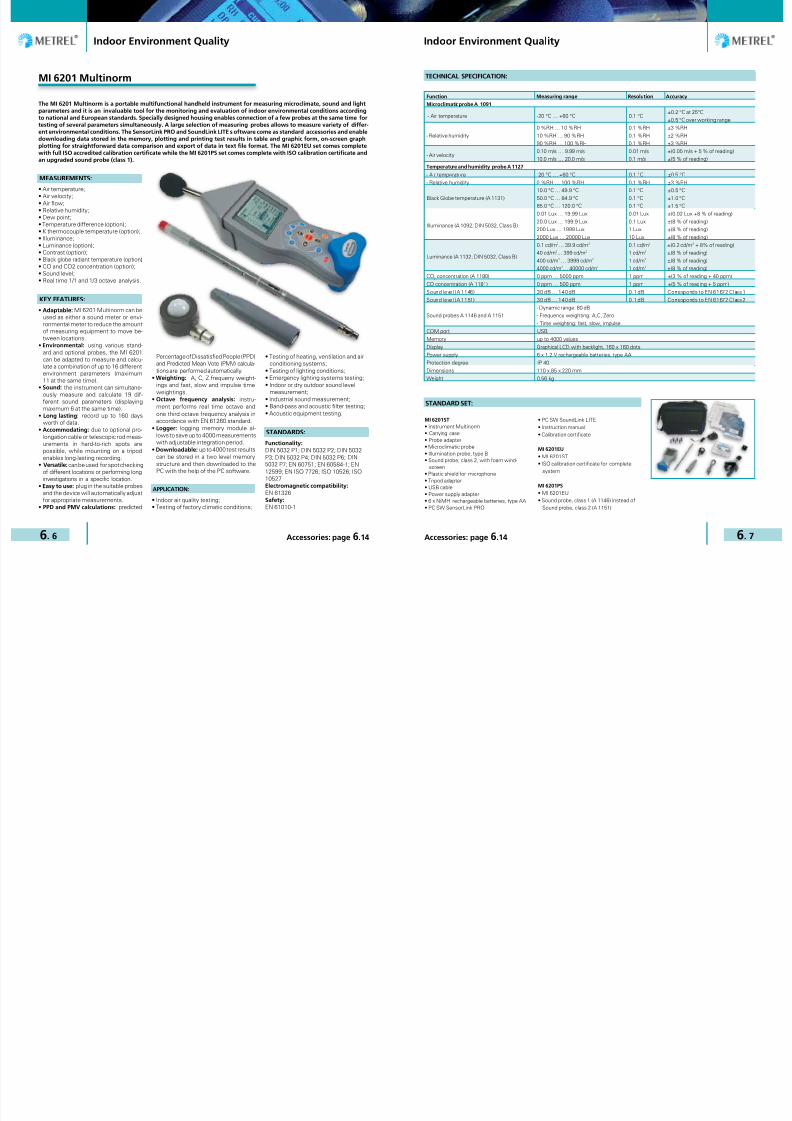
7/25/2019 METREL General Catalog Engl 2015
http://slidepdf.com/reader/full/metrel-general-catalog-engl-2015 96/121

7/25/2019 METREL General Catalog Engl 2015
http://slidepdf.com/reader/full/metrel-general-catalog-engl-2015 97/121
Indoor Environment Quality Indoor Environment Quality
6. 8 6. 9Accessories: page 6.14 Accessories: page 6.14
Sample of on-line reading data analysis withSoundLink PRO PC software.
KEY FEATURES
Logged data analysis with SoundLink PROPC software.
MI 6301 FonS
MEASUREMENTS:
• LXY (Time weighted sound level);• LXeq (Time average sound level);• LXYmax (Maximum time weighted
sound level);• LXYmin (Minimum time weighted
sound level);• LXpeak (Peak sound level);• LXE (Sound exposure level);• Percentile sound pressure level;• Real time 1/1 octave analysis;• Real time 1/3 octave analysis.
KEY FEATURES:
• Adaptable: the instrument can simul-taneously measure and calculate 19different sound parameters (displayingmaximum 6 at the same time).
• Weighting: A, C, Z frequeny weight-ings and fast, slow and impulse timeweightings in accordance with EN61672 standard.
• Dual measuring: two independentsound measuring channels that canbe set to different time and weightingsettings.
• Octave frequency analysis: instru-ment performs real time octave andone third octave frequency analysis inaccordance with EN 61260 standard.
• Long lasting: record up to 80 daysworth of data.
• Versatile: can be used for spot check-ing of different locations or performinglong investigations in a specific loca-tion.
• One stop readings: according to cus-tom configuration instrument can dis-play MAX, MIN, peak readings, equal-ised readings, channel 1 and channel2 readings.
• Logger: logging memory module al-lows to save up to 2000 measurementswith adjustable integration period.
• Downloadable: up to 2000 test resultscan be stored in the two level memorystructure and then downloaded to thePC with the help of the PC software.
The MI 6301 FonS is a professional sound analyser for sound measurements in accordance with EN 61672 standard Class1 or Class 2. The MI 6301 contains usual A, C and Z frequeny weightings and fast, slow and impulse time weightings andin addition the instrument has 2 independent measuring channels which can be set to different weightings. The MI 6301FonS is ideal for spot checking different locations or performing long term analysis of an area. The PC software SoundLinkLITE included in the standard set enables downloading, review, export and printing of test results while the optional PCSW SoundLink PRO enables full data analysis, charting and report generation.
APPLICATION:
• Indoor or dry outdoor sound levelmeasurement;
• Industrial sound measurement;• Acoustic equipment testing;• Band-pass and acoustic filter testing.
STANDARDS:
Functionality:EN 61672; EN 61260Electromagnetic compatibility:EN 61326Safety: EN 61010-1
Sound measurement, 1/1 and 1/3 octavian analisys. Recalling of memory, sample of help menu.
TECHNICAL SPECIFICATION:
Function Measuring range Resolution Accuracy
Sound level (A 1146) 30 dB … 140 dB 0.1 dB Corresponds to EN 61672 Class 1
Sound level (A 1151) 30 dB … 140 dB 0.1 dB Corresponds to EN 61672 Class 2
Sound probes A 1146 and A 1151- Dynamic range: 80 dB- Frequency weighting: A,C, Zero- Time weighting: fast, slow, impulse
COM port USB
Memory 2000 values
Display Graphical LCD with backlight, 160 x 160 dots
Power supply 6 x 1.2 V rechargeable batteries, type AA
Protection degree IP 40
Dimensions 110 x 85 x 220 mm
Weight 0.56 kg
MI 6301EU• Instrument FonS• Carrying case• Sound probe, class 2, with foam wind-
screen• Plastic shield for microphone• Tripod adapter• USB cable• Power supply adapter• 6 x NiMH rechargeable batteries, type AA
• PC SW SoundLink LITE• Instruction manual• Calibration certificate• ISO calibration certificate for complete
system
MI 6301PS• MI 6301EU• Sound probe, class 1 (A 1146) instead of
Sound probe, class 2 (A 1151)
STANDARD SET:
KEY FEATURES
PTB Approved

7/25/2019 METREL General Catalog Engl 2015
http://slidepdf.com/reader/full/metrel-general-catalog-engl-2015 98/121
Indoor Environment Quality Indoor Environment Quality
6. 10 6. 11Accessories: page 6.14 Accessories: page 6.14
MI 6401 Poly
MEASUREMENTS:
• Air temperature;
• Air velocity;• Air flow;• Relative humidity;• Dew point;• Temperature difference (option);• K thermocouple temperature (option);• Illuminance;• Luminance (option);• Contrast (option);• Black globe radiant temperature
(option);• CO and CO2 concentration (option).
KEY FEATURES:
• Adaptable: using various standardand optional probes, the MI 6401 canbe adapted to measure and calculate acombination of up to 16 different envi-ronments conditions (maximum 11 atthe same time).
• Long lasting: record up to 160 daysworth of data.
• Accommodating: due to optional pro-longation cable or telescopic rod meas-
urements in hard-to-rich spots arepossible, while mounting on a tripodenables long-lasting recording.
• Versatile: can be used for spot check-ing of different locations or performinglong investigations in a specific loca-tion.
• Easy to use: plug in the suitable probesand the device will automatically adjustfor appropriate measurements.
• PPD and PMV calculations: predictedPercentage of Dissatisfied People(PPD) and Predicted Mean Vote (PMV)calculations are performed automati-cally.
• Logger: logging memory module al-lows to save up to 4000 measurementswith adjustable integration period.
• Downloadable: up to 4000 test resultscan be stored in a two level memorystructure and then downloaded to thePC with the help of the PC softwareSensorLink PRO.
APPLICATION:
• Indoor air quality testing;• Testing of factory climatic conditions;• Testing of heating, ventilation and air
conditioning systems;• Testing of lighting conditions;• Emergency lighting systems testing.
The MI 6401 Poly is a portable multifunctional handheld instrument for measuring microclimate and light parameters suchas Illuminance, humidity, air temperature and air velocity of an environment. Emergency lighting, ventilation systems,lighting conditions, air conditioning systems, factory conditions, production line conditions and many more can be testedby the MI 6401. Specially designed housing enables connection of a few probes at the same time for testing of severalparameters simultaneously. All the results can be stored in the internal memory of the instrument and then downloadedto PC via the SensorLink PRO software which is included in the standard set. For full data traceability to internationalstandards the MI 6401EU set includes a full ISO accredited calibration certificate.
STANDARDS:
Functionality:
DIN 5032 P1; DIN 5032 P2; DIN 5032
P3; DIN 5032 P4; DIN 5032 P6;
DIN 5032 P7; EN 60751; EN 60584-1;
EN 12599; EN ISO 7726; ISO 10526;
ISO 10527
Electromagnetic compatibility:
EN 61326
Safety:
EN 61010-1
TECHNICAL SPECIFICATION:
Function Measuring range Resolution Accuracy
Microclimatic probe A 1091
- Air temperature -20 °C … +60 °C 0.1 °C±0.2 °C at 25°C
±0.5 °C over working range
- Relative humidity
0 %RH … 10 %RH
10 %RH … 90 %RH
90 %RH … 100 %RH
0.1 %RH
0.1 %RH
0.1 %RH
±3 %RH
±2 %RH
±3 %RH
- Air velocity0.10 m/s … 9.99 m/s
10.0 m/s … 20.0 m/s
0.01m/s
0.1m/s
±(0.05 m/s + 5% of reading)
±(5% of reading)
Temperature and humidity probe A 1127
- Air temperature -20 °C … +60 °C 0.1 °C ±0.5 °C
- Relative humidity 0 %RH … 100 %RH 0.1 %RH ±3 %RH
Black Globe temperature (A 1131)10.0 °C … 49.9 °C50.0 °C … 84.9 °C
85.0 °C … 120.0 °C
0.1 °C0.1 °C
0.1 °C
±0.5 °C±1.0 °C
±1.5 °C
Illuminance (A 1092; DIN 5032, Class B)
0.01 Lux … 19.99 Lux
20.0 Lux … 199.9 Lux
200 Lux … 1999 Lux
2000 Lux … 20000 Lux
0.01 Lux
0.1 Lux
1 Lux
10 Lux
±(0.02 Lux +8 % of reading)
±(8 % of reading)
±(8 % of reading)
±(8 % of reading)
Luminance (A 1132; DIN 5032, Class B)
0.1 cd/m2… 39.9 cd/m2
40 cd/m2… 399 cd/m2
400 cd/m2 … 3999 cd/m2
4000 cd/m2… 40000 cd/m2
0.1 cd/m2
1 cd/m2
1 cd/m2
1 cd/m2
±(0.2 cd/m2 + 8 % of reading)
±(8 % of reading)
±(8 % of reading)
±(8 % of reading)
CO2 concentration (A 1180) 0 ppm … 5000 ppm 1 ppm ±(3 % of reading + 40 ppm)
CO concentration (A 1181) 0 ppm … 500 ppm 1 ppm ±(5 % of reading + 5 ppm)
COM port USB
Memory 4000 values
Display Graphical LCD with backlight, 160 x 160 dots
Power supply 6 x 1.2 V rechargeable batteries, type AA
Protection degree IP 40
Dimensions 110 x 85 x 220 mm
Weight 0.56 kg
MI 6401ST• Instrument Poly• Carrying case• Probe adapter• Microclimatic probe• Illumination probe, type B• Tripod adapter• USB cable• Power supply adapter• 6 x NiMH rechargeable batteries, type AA
• PC SW SensorLink PRO• Instruction manual• Calibration certificate
MI 6401EU
• MI 6401ST• ISO calibration certificate for complete
system
STANDARD SET:

7/25/2019 METREL General Catalog Engl 2015
http://slidepdf.com/reader/full/metrel-general-catalog-engl-2015 99/121
Indoor Environment Quality Indoor Environment Quality
6. 12 6. 13Accessories: page 6.14 Accessories: page 6.14
SensorLink SoundLink
KEY FEATURES:
• Automatic recognition of the instru-ment: connected instrument to the PC isautomatically recognized by the software.
• Logger, Memory, Download: Storedand downloaded data from the instru-
ment could be organized, selected togroup, viewed and compared for ana-lyzing in graphs and tabelaric formsand printed in a report form.
• Export of test results: test results intext format can be exported to otherprograms (MS Excel, MS Word).
• Test Reports: automatic generation oftest reports from the selected viewsand data with attached graphs.
PC SW SensorLink is compatible with:• MI 6201 Multinorm• MI 6401 Poly
KEY FEATURES:
• User friendly interface: wide range ofquick icons, for downloading, export-ing, viewing and reorganizing data.
• Structure organized data: download-ed data are organized into tree struc-
ture where the locations could berenamed and / or equiped with com-ments.
• Data filtering and combining loggermeasurements as a function of time.
• Zoom in Logger window: Drag it andzoom rectangle will be drawn.
• Spectrum window: graph area andvalues area will show Octave and 1/3Octave bars for analysis where select-ed logger or single 1/3 result showsfour broadband values and 27 spectralcomponents of the signal. Broadbandvalues are shown as blue bars andevery spectral component is shownas one bar with three different colours(each one for minimum, average andmaximum).
• Results window: shows in tabularform values of measurements addedfrom Tree window. Location name,start and end time and selected meas-urements are displayed in each line oftable.
The SensorLink software works in conjunction with Metrel downloadable Indoor Environment Quality testers. The soft-ware automatically recognizes connected instrument and allows the customer to download test results saved on theinstrument, review the results and print test reports. The Sensor Link is compatible with Metrel instruments MI 6201Multinorm and MI 6401 Poly.
The Sound Link software works as a program for downloading, storing and retrieving measurement data from Metrelinstruments MI 6201 Multinorm and MI 6301 FonS.
PC SOFTWARE PC SOFTWARE
Table with downloaded results of allconnected probes
Draw a graphs of logged parameters
Measurements dialog offering widerange of available recorded measure-ments from instrument to be added orremoved from analysis.
SoundLink PC SW Tool for Analysing andReporting
• Add/remove measurements dialog: In the same dialog you can select ordeselect measurements that will bedisplayed in the table of Results win-
dow.• Export of test results: test results can
be exported to other programs (MS Ex-cel, MS Word).
• Test Reports: automatic generation oftest reports from the selected viewsand data with attached graphs.
PC SW SoundLink is compatible with:
• MI 6201 Multinorm• MI 6301 FonS
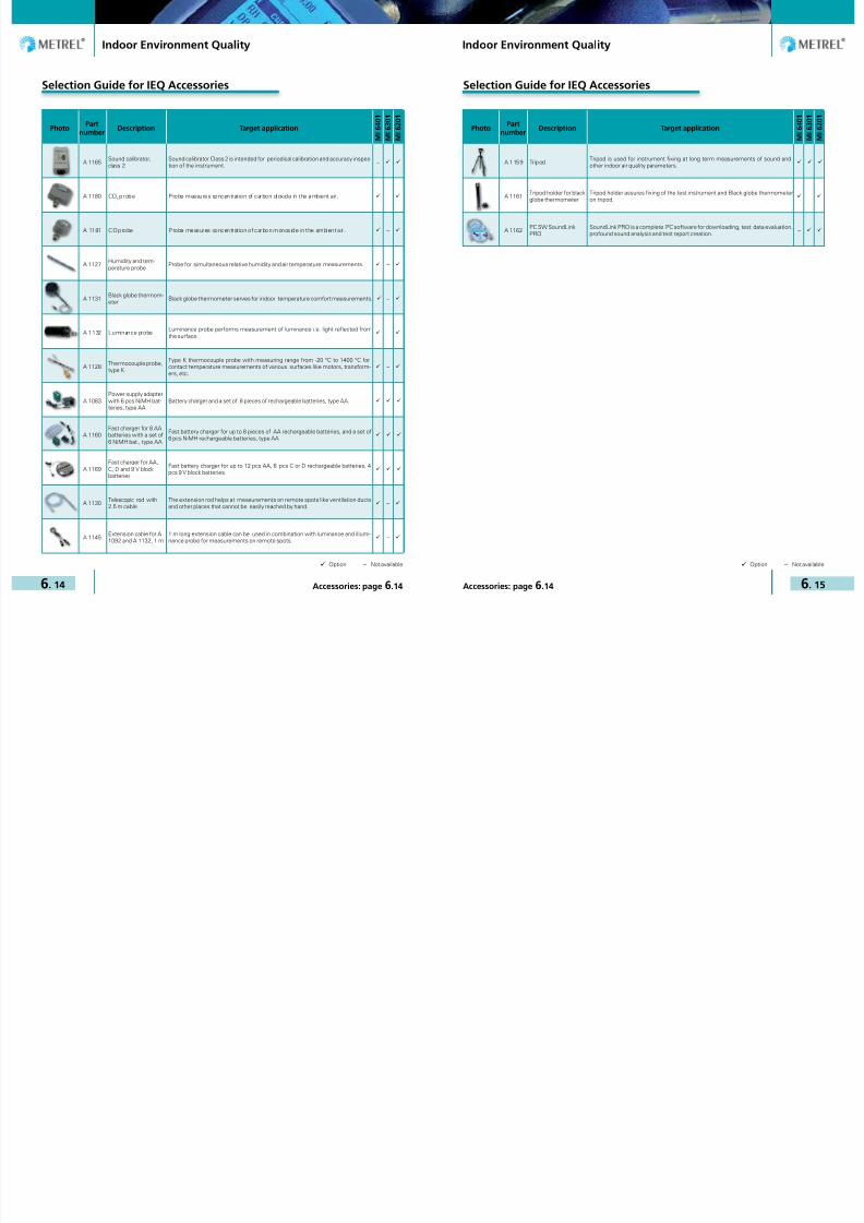
7/25/2019 METREL General Catalog Engl 2015
http://slidepdf.com/reader/full/metrel-general-catalog-engl-2015 100/121
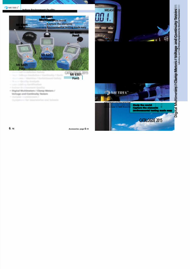
7/25/2019 METREL General Catalog Engl 2015
http://slidepdf.com/reader/full/metrel-general-catalog-engl-2015 101/121
Accessories: page 7.32
Indoor Environment Quality
6. 16 Accessories: page 6.14
GOOD TO KNOW Digital Multimeters / Clamp Meters / Voltage and Continuity Tester 7 - 02DIGITAL MULTIMETERSSelection Guide for Digital Multimeters 7 - 03 MD 9060 TRMS, 500.000 counts LCD, 100kHz Voltage BandwidthHeavy Duty Industrial Multimeterr 7 - 06
MD 9050 TRMS Heavy Duty Industrial Digital Multimeter 7 - 08 MD 9040 TRMS Industrial Digital Multimeter 7 - 09 MD 9035 Automotive Multimeter Designed to Work On Real-WorldCar Signals 7 - 10
MD 9030 TRMS General Purpose Digital Multimeter 7 - 11 MD 9020 General Purpose Digital Multimeter 7 - 12 MD 9016 Electrical Field Service Multimeter 7 - 13 MD 9015 Electrical Field Service Digital Multimeter 7 - 14 MD 9010 General Purpose Autocheck Digital Multimeter 7 - 15CLAMP METERSSelection Guide for Clamp Meters 7 - 16 MD 9272 Leakage Clamp TRMS Meter with Power Functions 7 - 18 MD 9250 Industrial TRMS AC/DC CAT IV /1000 V 7 - 19 MD 9240 TRMS Power Clamp Meter 7 - 20 MD 9235 TRMS Power Clamp Meter, 3-Phase, Unbalanced-Load 7 - 21 MD 9230 Industrial TRMS AC/DC Current Clamp Meter 7 - 22 MD 9225 Most Complete Industrial TRMS AC/DC Current Clamp Meter 7 - 23 MD 9220 TRMS Current Clamp Meter 7 - 24
MD 9210 Mini Clamp Meter 7 - 25VOLTAGE AND CONTINUITY TESTERSelection Guide for Voltage and Continuity Testers 7 - 26 MD 1155 LED Voltage / Continuity Tester 7 - 27 MD 1055 LCD Voltage / Continuity Tester 7 - 28 MD 1160 LED Voltage / Continuity Tester 7 - 29 MD 1060 LCD Voltage / Continuity Tester 7 - 30NON CONTACT VOLTAGE DETECTORSMD 115 Non Contact Voltage Detector 7 - 31
MD 105 Non Contact Voltage Detector 7 - 31Selection Guide for DMM Accessories 7 - 32
D i g i t a l M u l t i m e t
e r s / C l a m p M e t e r s / V o l t a g e
a n d C o n t i n u i t y T e s t e r s
L a b r a t o r y a n d F i e l d T e
s t i n g E q u i p m e n t f o r E l e c t r i c a l P a r a m e t e r sMEASURING INSTRUMENTS AND TESTERS
MI 6401Poly
MI 6301FonS
MI 6201Multinorm
Study the worldCapture the elementsEnvironmental testing made easy
Digital Multimeters / Clamp Meters /
Voltage and Continuity Testers
CATALOGUE 2015

7/25/2019 METREL General Catalog Engl 2015
http://slidepdf.com/reader/full/metrel-general-catalog-engl-2015 102/121
Digital Multimeters/Clamp Meters/Voltage and Continuity Testers Digital Multimeters/Clamp Meters/Voltage and Continuity Testers
7. 2 7. 3Accessories: page 7.32 Accessories: page 7.32
Multimeter/Clamp/Voltage and Continuity Testers Multimeter/Clamp/Voltage and Continuity Testers
Find out more about DMMs andClamp Meters.Handheld digital multimeters (DMM)are among the most widely used instru-ments for equipment testing when itcomes to servicing, repairing, and install-ing applications.
A DMM is a digital meter that is capa-ble of making various types of measure-ment. It may have any number of special
features, but mainly a DMM measuresvolts, ohms, and amperes. DMMs areused to troubleshoot electrical problemsin a wide array of industrial and house-hold devices such as batteries, motorcontrols, appliances, power supplies,and wiring systems.
Metrel DMMs are appropriate for test-ing under tough conditions and can betossed into tool cases.
When choosing a clamp meter not onlylook at specifications, but also pay at-tention to features, functions, and theoverall value represented by a meter’sdesign:• Choose a clamp meter that gives ac-
curate and repeatable results.• For precise measurements choose
a clamp meter which reports TRMSreading. Otherwise noise from every-thing from a variable frequency driveto compact fluorescent bulbs can re-sult in a less accurate reading.
• Make sure that the clamp meter isspecified to work in the environmentyou do and that are rugged enough tocontinue to give reliable results even incase they drop from ladders or bounc-ing in your tool case.
• Be sure the clamp meter display haslarge, easy to read characters.
RMS (Root Mean Square) valueWhen an AC supply is placed onto a cir-cuit, it produces heat. The RMS value isthe equivalent DC supply that would pro-duce the same amount of thermal heatas the actual AC supply.
TRMS (True RMS) valueTRMS is a specific method of measuringthe RMS value of a signal. With induc-tive and capacitive systems distortingthe sinusoidal wave of the mains supply,this method provides the most ac curateRMS value regardless of the shape ofthe waveform.
ResolutionResolution is the smallest possiblechange in a signal that would producea change in the value on the screen ofthe test instrument. For example, if theDMM has a resolution of 1 mV on the 4V range, it is possible to see a change of1 mV (1/1000 of a volt) while reading 1 V.
AccuracyAccuracy is a value to show how accu-rately an instrument can read a specificvalue. This is usually written as a per-centage (e.g. 5 V ± 5 %). An accuracy ofone percent of reading means that for adisplayed reading of 100 volts, the actualvalue of the voltage could be anywherebetween 99 volts and 101 volts.
Number of Counts The number of divisions into which agiven measuring range is divided. Thiscan be used to evaluate the resolution ofan instrument.
The basics of measurementsDC and AC voltageOne of the most basic tasks of a DMMis measuring voltage. A typical DC volt-age source are the batteries while ACvoltage is usually created by a generator.The wall outlets are common sources ofAC voltage.
Testing for proper supply voltage is usu-ally the first step when troubleshootinga circuit. If there is no voltage present,or if it is too high or too low, the voltageproblem should be corrected before in-vestigating further.
GOOD TO KNOW GOOD TO KNOW
A DMM’s ability to measure AC volt-age can be limited by the frequency ofthe signal. Most DMMs can accuratelymeasure AC voltages with frequenciesfrom 50 Hz to 500 Hz, but a DMMs ACmeasurement bandwidth may be hun-dreds of kilohertz wide. Such a metermay read a higher value because it iscapable to see more of a complex ac sig-nal. DMM accuracy specifications for ACvoltage and AC current should state thefrequency range along with the range’s
accuracy.
Frequency is measured in hertz (Hz) thenumber of times per second a waveformrepeats. Maintaining the right frequencyis crucial for devices that rely on AC volt-age and current.
Crest factor The crest factor describes the ratio of thepeak value to the RMS value of an electricalvariable (AC voltage and AC current).High crest factors cause distortionof the reactive power and harmon-ics in the supply network, and so areundesirable.
ResistanceResistance values can vary greatly, froma few milliohms (mΩ) for contact resist-ance to billions of ohms for insulators.Most DMMs measure from 0.1 Ω, upto 300 MΩ. At Metrel DMM display isinfinite resistance (open circuit) read as
“OL” and means that the resistance isgreater than the meter can measure. Re-sistance measurements must be madewith the circuit power off – otherwise,the meter or circuit could be damaged.
ContinuityContinuity is a quick “go/no-go” resist-ance test that distinguishes between anopen and a closed circuit. A DMM witha continuity beeper allows you to com-plete many continuity tests easily andquickly. The DMM will beep if there isgood continuity, or a good path that al-lows current to flow. If there is no conti-nuity, the DMM won’t beep.
Diode testThis mode measures and displays theactual voltage drop across a junction. Asilicon junction should have a voltagedrop less than 0.7 V when applied in theforward direction and an open circuitwhen applied in the reverse direction.When the red (+) lead is connected tothe anode and the black (-) to the cath-ode, the diode should conduct and themeter will display a value (usually the
voltage across the diode in mV, 1000mV= 1V). After rversing the connectionsthe diode should not conduct this wayso the meter will display “OL”.
Capacitance To test capacitance, set the dial on theDMM to the capacitance function andplug in your leads. After ensuring thatthe capacitor has been discharged, con-nect the test leads to the capacitor ter-minals and take a reading. If the meas-urement is similar to the rating listed onthe capacitor, the capacitor is good. Asignificant variation from the rating indi-cates the capacitor should be replaced.
DC and AC currentCurrent measurements are differentfrom other DMM measurements. Cur-rent measurements taken with theDMM alone require placing the meter inseries with the circuit being measured.This means opening the circuit and usingthe DMM test leads to complete the cir-cuit. This way all the circuit current flowsthrough the DMMs circuitry.
Current with Clamp MeterToday’s clamp meters are capable ofmeasuring both AC and DC current.Typical current measurements are takenon various branch circuits of an electri-cal distribution system. By taking currentmeasurements along the run of a branchcircuit, it can be easily determined howmuch each load along the branch circuitis drawing from the distribution system.

7/25/2019 METREL General Catalog Engl 2015
http://slidepdf.com/reader/full/metrel-general-catalog-engl-2015 103/121
Digital Multimeters/Clamp Meters/Voltage and Continuity Testers Digital Multimeters/Clamp Meters/Voltage and Continuity Testers
7. 4 7. 5Accessories: page 7.32 Accessories: page 7.32
Selection Guide for Multimeters
Part No.: MD 9060 MD 9050 MD 9040 MD 9035 MD 9030 MD 9020 MD 9016 MD 9015 MD 9010
True RMS − − − − −DC current range (A) 10 10 10 10 10 10 8 10 0.002Basic accuracy (%) 0.15 0.2 0.2 0.7 1.2 1.2 0.5 0.8 1.2
Maximum resolution (µA) 0.1 0.1 0.1 0.1 0.1 0.1 0.1 0.1 0.1AC current range (A) 10 10 10 10 10 10 8 10 0.002Basic accuracy (%) 0.5 0.6 0.6 2.2 1.5 1.5 1.0 1 1.5Maximum resolution (µA) 0.1 0.1 0.1 0.1 0.1 0.1 0.1 0.1 0.1DC voltage range (V) 1000 1000 1000 1000 1000 1000 1000 1000 600Basic accuracy (%) 0.02 0.06 0.06 0.4 0.3 0.3 0.4 0.3 0.5Maximum resolution (µV) 10 10 10 10 100 100 10 100 1000AC voltage range (V) 1000 1000 1000 1000 1000 1000 1000 750 600Basic accuracy (%) 0.3 0.5 0.5 2.0 1.5 1.5 1.0 1 1.5Maximum resolution (µV) 10 10 10 10 100 100 10 100 1000Resistance measurement (MΩ) 50 60 60 60 40 40 60 25 6Basic accuracy (%) 0.07 0.1 0.1 0.5 0.6 0.6 0.5 0.4 1Maximum resolution (mΩ) 100 100 100 100 100 100 100 100 100Acoustic continuity test
Diode test
Capacitance
Frequency measurement
Frequency of digital signals − − − − −
Temperature measurement (Type K sensor) T1 & T2(temperature comparison)
T1 & T2(temperature comparison)
− T1 T1 T1 T1 T1 −
Autocheck® V / Ω − − − − − − −
Conductance (nS) − − − − − − −IP-RPM (Inductive pickup type) − − − − − − − −IG-RPM (Contact signal type) − − − − − − − −Dwell – Angle function − − − − − − − −% - Duty Function − − − − − − − −Fuel injection – ms detector − − − − − − − −100 kHz Voltage Bandwidth − − − − − − − −Variable frequency drive − − − − − − − −
Count50.000 (fast mode)
500.000 (DCV)99.999 (Hz)
9999 (AC/DCV, Hz, nS)6000 (mV, µ/m/A, Ω , F) 6000 4000 4000 6000 2500 6000
Backlight − − − − −Analogue bar-graph 41 segment 41 segment 41 segment 24 segment − − 24 segment − −IR, RS232 interface − − − −Automatic and manual range selection AutoAutomatic switch off
Non-contact eletrical field detection (EF) − − − − −
MAX hold − − − − −Peak hold − − − − − − −Data hold −Recording (MAX / MIN / AVG) − − − − − −Relative value − −Compensation for test leads − − − − − − −
Overvoltage category CAT IV / 1000 V CAT IV / 1000 V CAT IV / 1000 V CAT II / 1000 VCAT IV / 300 VCAT III / 600 VCAT II / 1000 V
CAT IV / 300 VCAT III / 600 VCAT II / 1000 V
CAT IV / 300 VCAT III / 600 VCAT II / 1000 V
CAT IV / 300 VCAT III / 600 VCAT II / 1000 V
CAT III / 300 VCAT II / 600 V
Dimensions with holster (mm) 208 x 103 x 64.5 208 x 103 x 64.5 208 x 103 x 64.5 161 x 80 x 50 198 x 97 x 55 198 x 97 x 55 161 x 80 x 50 160 x 82 x 48 113 x 53 x 10.2Weight with holster (g) 635 635 635 340 396 396 340 345 78CE mark
DIGITAL MULTIMETERS DIGITAL MULTIMETERS

7/25/2019 METREL General Catalog Engl 2015
http://slidepdf.com/reader/full/metrel-general-catalog-engl-2015 104/121

7/25/2019 METREL General Catalog Engl 2015
http://slidepdf.com/reader/full/metrel-general-catalog-engl-2015 105/121
Digital Multimeters/Clamp Meters/Voltage and Continuity Testers Digital Multimeters/Clamp Meters/Voltage and Continuity Testers
7. 8 7. 9Accessories: page 7.32 Accessories: page 7.32
MD 9050 TRMS Heavy Duty Industrial Digital Multimeter
The MD 9050 ranks among the best multimeters on the market. High resolution and accuracy, 2-line LCD display, fast data acquisi-tion and transfer (via optical interface), CAT IV / 1000 V, TRMS current and voltage measurement, non-contact voltage detection,conductance measurement, auto check function and fast one-handed operation are highlights of the multimeter. The MD 9050is the ideal choice for demanding measurement tasks in industry, in the laboratories and in everyday repair and maintenancepractice.
TECHNICAL SPECIFICATION:
MEASURING FUNCTIONS:
• TRMS AC, DC voltage measurement;• TRMS AC, DC current measurement;• Capacitance measurement;• Resistance measurement;• Diod test;• Mains supply frequency measurement;• Frequency of digital signals measurement;• Continuity test (acoustic signalling);• Conductance measurement;• Electric field detection;• Temperature measurement.
KEY FEATURES:
• TRMS: accurate readings on sinusoidaland non-sinusoidal signals.
• Autocheck function: automatic de-tection of AC voltage, DC voltage orresistance.
• Auto-ranging: user can switch be-tween auto and manual ranging.
• Temperature measurement: meas-ures T1, T2 and T1 + T2 temperaturein Celsius and in Fahrenheit.
• EF detection: non-contact and probe-contact electric field detection.
• Lead alert: incorrect lead connection alert.• Relative zero mode: relative function
for comparing the difference betweensignals or removing background noise.
• MAX/MIN/AVG: recording of maxi-mum, minimum and average values.
• Data Hold: data hold feature freezesthe display for later view.
• Peak Hold: Crest (instantaneous peak)cupture mode.
• PC Link: test results can be download-ed to the computer via the optional PCsoftware.
• Safety: CAT IV / 1000 V overvoltageprotection.
• Backlight: large bright 4 digits 9999counts dual LCD display with backlightfor working in dark conditions.
APPLICATION:
• High level industrial testing;• High level electronic fault finding;• Field servicing;• Heavy duty electrical testing.
STANDARD SET:
• Multimeter MD 9050 with rubber holster• Test lead with probe, 2 pcs• Thermocouple probe, type K• 9 V battery• Instruction manual• Warranty
Function Range AccuracyTRMS AC and AC+DC voltage(40 Hz … 20 kHz) 60.00 mV … 999.9 V from ±(0.5 % of reading + 3 digits)
to ±(3.0 % of reading + 4 digits)
Autocheck (ACV) 9.999 V … 999.9 V ±(1.0 % of reading + 4 digits)
DC voltage 60.00 mV … 999.9 V from ±(0.06 % of reading + 2 digits)to ±(0.12 % of reading + 2 digits)
Autocheck (DCV) 9.999 V … 999.9 V ± (0.5 % of reading + 3 digits)
DC current 600.0 µA … 10.00 A ±(0.2 % of reading + 4 digits)
TRMS AC and AC+DC current(40 Hz … 1 kHz) 600.0 µA … 10.00 A from ±(0.6 % of reading + 3 digits)
to ±(1.0 % of reading + 4 digits)
Diode test 2.000 V ±(1.0 % of reading + 1 digit)Open-circuit voltage <3.5 VDC, test current 0.4 mA
Resistance 600.0Ω … 60.00 MΩfrom ±(0.1 % of reading + 3 digits)to ±(1.5 % of reading + 5 digits)
Conductance 99.99 nS ±(0.8 % of reading + 10 digits)
Autocheck (resistance) 600.0Ω … 60.00 MΩfrom ± (0,5 % of reading + 4 digits)to ±(2 % of reading + 5 digits)
Mains frequency 15.00 Hz … 50.00 kHz ±(0.04 % of reading + 4 digits)
Frequency of digital equipment 5.00 Hz … 1.000 MHz ±(0.004 % of reading + 4 digits)
Capacitance 60.00 nF … 25.00 mF from ±(0.8 % of reading + 3 digits)to ±(6.5 % of reading + 5 digits)
Temperature -50 °C … +1000 °C ±(0.3 % of reading +2 °C)
Power supply 9 V batt ery (NEDA1604G, JIS006P, or IEC6F22)Overvoltage category CAT IV / 1000 VDimensions 208 x 103 x 64.5 mmWeight 635 g
DIGITAL MULTIMETERS
TECHNICAL SPECIFICATION:
MD 9040 TRMS Industrial Digital Multimeter
CAT IV / 1000 V overvoltage category and TRMS measurement of AC current and voltage are key features of the MD 9040.That’s why it is particularly suitable for performing measurements on power supply sources in the most demanding ap-plications in the industrial sector. Its high accuracy, 2-line LCD display, diverse measurement functions, fast one-handedoperation and outstanding value for money open up a wide range of possible uses.
MEASURING FUNCTIONS:
• TRMS AC, DC voltage measurement;• TRMS AC, DC current measurement;• Capacitance measurement;• Resistance measurement;• Diod test;
• Mains supply frequency measurement;• Frequency of digital signals measurement;• Continuity test (acoustic signalling).
KEY FEATURES:
• TRMS: accurate readings on sinusoidaland non-sinusoidal signals.
• Lead alert: incorrect lead connectionalert.
• Auto-ranging: user can switch between
auto and manual ranging.
• Relative zero mode: relative functionfor comparing the difference betweensignals or removing background noise.
• MAX/MIN/AVG: recording of maxi-mum, minimum and average values.
• Data Hold: data hold feature freezesthe display for later view.
• PC Link: test results can be download-ed to the computer via the optional PCsoftware.
• Frequency measurement: up to 1MHz.
• Safety: CAT IV / 1000 V overvoltage
protection.
• Easy to read: large bright 4 digits 9999counts dual LCD display.
APPLICATION:
• High level industrial testing;• High level electronic fault finding;• Field servicing;• Heavy duty electrical testing.
STANDARD SET:
• Multimeter MD 9040 with rubber holster• Test lead with probe, 2 pcs• 9 V battery• Instruction manual• Warranty
Function Range Accuracy
TRMS AC voltage(40 Hz … 20 kHz)
60.00 mV … 999.9 Vfrom ±(0.5 % of reading + 3 digits)to ±(3.0 % of reading + 4 digits)
DC voltage 60.00 mV … 999.9 V from ±(0.06 % of reading + 2 digits) to ±(0.12 % of reading + 2 digits)
DC current 600.0 µA … 10.00 A ±(0.2 % of reading + 4 digits)
TRMS AC current(40 Hz … 1 kHz)
600.0 µA … 10.00 Afrom ±(0.6 % of reading + 3 digits)to ±(1.0 % of reading + 4 digits)
Diode test2.000 V ±(1.0 % of reading + 1 digit)
Open-circuit voltage <3.5 VDC, Test current 0.4 mA
Resistance 600.0 Ω … 60.00 MΩfrom ±(0.1 % of reading + 3 digits)to ±(1.5 % of reading + 5 digits)
Mains frequenc y 15. 00 Hz … 50. 00 kHz ± (0 .04 % of read ing + 4 d ig its)
Frequency of digital equipment 5.00 Hz … 1.000 MHz ±(0.004 % of reading + 4 digits)
Capacitance 60.00 nF … 25.00 mFfrom ±(0.8 % of reading + 3 digits)to ±(6.5 % of reading + 5 digits)
Po wer su pp ly 9 V bat te ry (N ED A1 60 4G , J IS 00 6P, or IEC 6F 22 )
Overv ol ta ge c ategory CAT I V / 1000 V
Dimensions 208 x 103 x 64.5 mm
Weight 635 g
DIGITAL MULTIMETERS

7/25/2019 METREL General Catalog Engl 2015
http://slidepdf.com/reader/full/metrel-general-catalog-engl-2015 106/121
Digital Multimeters/Clamp Meters/Voltage and Continuity Testers Digital Multimeters/Clamp Meters/Voltage and Continuity Testers
7. 10 7. 11Accessories: page 7.32 Accessories: page 7.32
TECHNICAL SPECIFICATION:
MD 9030 TRMS General Purpose Digital Multimeter
The MD 9030 TRMS digital multimeter has been designed for use both in the laboratories and in the harsh industrial main-tenance and repair sector. TRMS functionality makes the multimeter suitable for a m ultitude of situations, while the largebright screen with backlight and incorrect lead connection alert make it ideal for working in dark areas.
MEASURING FUNCTIONS:
• TRMS AC, DC voltage measurement;• TRMS AC, DC current measurement;• Capacitance measurement;• Resistance measurement;• Diod test;• Frequency measurement;• Continuity test (acoustic signalling);• Temperature measurement.
KEY FEATURES:
• TRMS: accurate readings on sinusoidaland non-sinusoidal signals.
• Temperature measurement: meas-ures temperature in Celsius up to 300°C and in Fahrenheit up to 572 °F.
• Frequency measurement: up to 1 MHz.• Lead alert: incorrect lead connection alert.• Auto-ranging: user can switch be-
tween auto and manual ranging.• Relative zero mode: relative function
for comparing the difference betweensignals or removing background noise.
• Data Hold: data hold feature freezesthe display for later view.
• MAX Hold: MAX hold feature freezesthe maximum measured value.
• Safe: CAT IV / 300 V, CAT III / 600 V andCAT II / 1000 V overvoltage protection.
• Backlight: large bright 3-3/4 digits,4000 counts LCD display with back-light for working in dark conditions.
APPLICATION:
• Mid level electrical testing;• Mid level electronic fault finding;• Field servicing;• General purpose.
STANDARD SET:
• Multimeter MD 9030 with rubber holster• Test lead with probe, 2 pcs• 1.5 V battery, type AAA, 2 pcs• Instruction manual• Warranty
Function Range Accuracy
DC voltage 400.0 mV … 1000 Vfrom ±(0.3 % of reading + 4 digits)to ±(1.0 % of reading + 4 digits)
TRMS AC voltage(50 … 500 Hz)
400.0 mV … 1000 Vfrom ±(1.5 % of reading + 5 digits)to ±(4.0 % of reading + 5 digits)
DC current 400.0 µA … 10.00 Afrom ±(1.2 % of reading + 3 digits)to ±(2.0 % of reading + 5 digits)
TRMS AC current 400.0 µA … 10.00 Afrom ±(1.5 % of reading + 4 digits)to ±(2.0 % of reading + 6 digits)
Diode test Open-circuit voltage <1.6 VDC, Test current 0.25 mA
Resistance 400.0 Ω … 40.00 MΩfrom ±(0.6 % of reading + 4 digits)to ±(2.0 % of reading + 4 digits)
Temperature -20 °C … 300 °C ±(2.0 % of reading + 3 °C)
Frequency 50.00 Hz … 1.000 MHz ±(0.5 % of reading + 4 digits)
Capacitance 500.0 nF … 3000 µF ±(3.5 % of reading + 6 digits)
Power supply 2 x 1.5 V batteries, type AAA
Overvoltage category CAT IV / 300 V; CAT III / 600 V; CAT II / 1000 V
Dimensions 198 x 97 x 55 mm
Weight 396 g
DIGITAL MULTIMETERS DIGITAL MULTIMETERS
MEASURING FUNCTIONS:
• AC, DC voltage measurement;• AC, DC current measurement;• Capacitance measurement;• Resistance measurement;• Diode test;
• Both IP (inductive) & IG (contact) RPM;• ms Fuel-injection on time;• % Duty cycle;• Dwell angle;• Line-Level Hz (ACV, DCV);• Frequency measurement;• Continuity test (acoustic signaling);• Electric field detection;• Temperature measurement.
KEY FEATURES:
• Line-Level: measures frequency from10 Hz to 50 kHz.
• Auto-ranging: user can switch be-tween auto and manual ranging.
• Hold: data hold function freezes thedisplay for later view.
• Pickup clip: Inductive pickup clip ac-cessory for IP-RPM Function.
• 4 Selectable Trigger-Levels: For IP-RPM, IG-RPM, Dwell, %-Duty and msFunctions.
• Selectable Trigger: Positive (+) orNegative (-) Trigger for %-Duty and msFunctions.
• Selectable Cylinders: 1, 2, 3, 4, 5, 6,8, 10 or 12 Cylinders for Dwell and IG-RPM functions.
• Safe: CAT II / 1000 V, overvoltage pro-tection.
APPLICATION:
• Automotive industry;• High level industrial testing;• High level electronic fault finding;• Field servicing.
STANDARD SET:• Multimeter MD 9035 with rubber holster• Test lead with probe, 2 pcs• Thermocouple probe, type K• Inductive pickup clip• 1.5 V battery, type AAA, 2 pcs• Instruction manual• Warranty
MD 9035 Automotive Multimeter Designed to Work On Real-World Car Signals
Metrel MD 9035 is a unique automotive multimeter top class with many exciting features, such as: Selectable 4-stroke,4-DIS/2-stroke, & 2-DIS engine RPM; Selectable Trig (+) / Trig- on % & ms readings; Selectable Sensitivity-Levels on RPM,Dwell, % & ms readings, BeepJack warning, Backlit display and Display hold. MD 9035 is also equipped with automaticrange selection and extra fast analog bar-graph.
TECHNICAL SPECIFICATION:
Function Range Accuracy
DC Voltage 60.00 mV … 1000 V From ±(0.4% of reading + 3 digits)to ±(0.7% of reading + 3 digits)
AC Voltage(50 Hz … 500 Hz) 60.00 mV … 1000 V From ±(2.0% of reading + 5 digits)
to ±(2.2% of reading + 5 digits)
DC Current 600.0 µA … 10.00 A From ±(0.7% of reading + 3 digits)to ±(0.5% of reading + 3 digits)
AC Current(50 Hz … 500 Hz) 600.0 µA … 10.00 A From ±(2.2% of reading + 5 digits)
to ±(1.2% of reading + 5 digits)
Diode Test1.000 V ±(1.0% of reading + 3 digits)Open-circuit voltage < 1.6 V DC, Test current 0.50 mA
Resistance 600.0Ω … 60.00 MΩ From ±(0.5% of reading + 6 digits)to ±(1.5% of reading + 5 digits)
Capacitance 6.000 µF…2000 µF From ±(2.0% of reading + 5 digits)to ±(4.0% of reading + 5 digits)
Temperature
-50 °C…1 00 0 °C ± (0 .5 % o f r eadi ng + 3 di gi ts )
-58 °F …1 83 2 °F ± (0 .5 % o f r eadi ng + 6 di gi ts )
IP-RPMRPM 4 (240…20000 RPM)
±(2RPM)RPM 2 (120…10000 RPM)RPM 2M (60…5000 RPM)
IG-RPMRPM 4 (60…20000 RPM)
±(2RPM)RPM 2 (30…10000 RPM)RPM 2M (15…5000 RPM)
Dwell0. 0 ° .. . 36 0.0 ° ±( 1. 2 °/ kr pm + 1 di git)0 .0 % …100.0 % ±(0.04% /krpm /cyl + 2 d ig its)
Fuel injection-ms detector
PFI / Multi Point Injection0.05 ms … 250.0 ms ±(0.05 ms + 1 digit)0 .0 % . .. 10 0.0 % ± (0 .0 4 % /k rp m + 2 d ig it s)TBI / Single Point Injection0.05 ms ... 250.0 ms ±(0.05 ms + 1 digi t)0 .0 % ... 100.0% ±(0.04 % /krpm /cyl + 2 d ig its)
Function Range Sensitivity(Sin RMS) Accuracy
Hz (Line-level) ∞ACV & DCV
6 V 10 Hz…10 kHz 0.5 V±(0.1 %+ 3 digits)
60 V10 Hz…50 kHz
5 V600 V 50 V1000 V 45 Hz…1 kHz 500 V
P ower supply 2 x 1. 5 V ba tt eri es, ty pe AAAOvervoltage category CAT II / 1000 VDimensions 161 x 80 x 50 mmWeight 340 g

7/25/2019 METREL General Catalog Engl 2015
http://slidepdf.com/reader/full/metrel-general-catalog-engl-2015 107/121
Digital Multimeters/Clamp Meters/Voltage and Continuity Testers Digital Multimeters/Clamp Meters/Voltage and Continuity Testers
7. 12 7. 13Accessories: page 7.32 Accessories: page 7.32
DIGITAL MULTIMETERS
TECHNICAL SPECIFICATION: TECHNICAL SPECIFICATION:
MD 9020 General Purpose Digital Multimeter
The MD 9020 is a high-quality digital multimeter, designed for everyday use in the laboratory and for maintenance andrepair work in the field and in the industrial sector as well.
MEASURING FUNCTIONS:
• AC, DC voltage measurement;• AC, DC current measurement;• Capacitance measurement;• Resistance measurement;• Diod test;• Frequency measurement;• Continuity test (acoustic signalling);
• Temperature measurement.
KEY FEATURES:
• Temperature measurement: meas-ures temperature in Celsius up to 300°C and in Fahrenheit up to 572 °F.
• Frequency measurement: up to 1 MHz.
• Lead alert: incorrect lead connection alert.
• Auto-ranging: user can switch be-tween auto and manual ranging.
• Relative zero mode: relative functionfor comparing the difference betweensignals or removing background noise.
• Data Hold: data hold feature freezesthe display for later view.
• MAX Hold: MAX hold feature freezesthe maximum measured value.
• Safe: CAT IV / 300 V, CAT III / 600 V andCAT II / 1000 V overvoltage protection.
APPLICATION:
• Mid level electrical testing;• Mid level electronic fault finding;• Field servicing;• General purpose.
STANDARD SET:
• Multimeter MD 9020 with rubber holster• Test lead with probe, 2 pcs• 1.5 V battery, type AAA, 2 pcs• Instruction manual• Warranty
Function Range Accuracy
DC voltage 400.0 mV … 1000 Vfrom ±(0.3 % of reading + 4 digits)to ±(1.0 % of reading + 4 digits)
AC voltage (50 … 500 Hz) 400.0 mV … 1000 Vfrom ±(1.5 % of reading + 5 digits)to ±(4.0 % of reading + 5 digits)
DC current 400.0 µA … 10.00 Afrom ±(1.2 % of reading + 3 digits)to ±(2.0 % of reading + 5 digits)
AC current 400.0 µA … 10.00 Afrom ±(1.5 % of reading + 4 digits)to ±(2.0 % of reading + 6 digits)
Diode test Open-circuit voltage <1.6 VDC, Test current 0.25 mA
Resistance 400.0 Ω … 40.00 MΩfrom ±(0.6 % of reading + 4 digits)to ±(2.0 % of reading + 4 digits)
Temperature -20 °C … 300 °C ±(2.0 % of reading + 3 °C)
Frequency 50.00 Hz … 1.000 MHz ±(0.5 % of reading + 4 digits)
Capacitance 500.0 nF … 3000 µF ±(3.5 % of reading + 6 digits)
Power supply 2 x 1.5 V batteries, type AAA
Overvoltage category CAT IV / 300 V; CAT III / 600 V; CAT II / 1000 V
Dimensions 198 x 97 x 55 mm
Weight 396 g
DIGITAL MULTIMETERS
MEASURING FUNCTIONS:
• AC, DC voltage measurement;• AC, DC current measurement;• Capacitance measurement;• Resistance measurement;• Diode test;• Frequency measurement;• Continuity test (acoustic signaling);• Electric field detection;• Temperature measurement.
KEY FEATURES:
• Auto-ranging: user can switch be-tween auto and manual ranging.
• EF detection: non-contact and probecontact electric field detection.
• Relative zero mode: relative functionfor comparing the difference betweensignals or removing background noise.
• Hold: data hold function freezes thedisplay for later view.
• PC Link: test results can be download-ed to the computer via the optional PCsoftware.
• Safe: CAT II / 1000 V, CAT III / 600 V andCAT IV / 300 V overvoltage protection.
APPLICATION:
• HVAC (heating, ventilation and air con-ditioning) troubleshooting;
• Low level electrical testing;• Low level electronic fault finding;• Basic field servicing;• Hobby work.
STANDARD SET:
• Multimeter MD 9016 with rubber holster• Test lead with probe, 2 pcs• Thermocouple probe, type K• 1.5 V battery, type AAA, 2 pcs• Instruction manual• Warranty
MD 9016 Electrical Field Service Multimeter
The digital multimeter MD 9016 is a perfect combination of size, Innovative functions and built-in PC communication. Itis capable to detect and diagnose most electrical and electrotechnical problems. Display with large easy-to-read figuresand one-handed operation make MD 9016 an extremely easy-to-use. This compact instrument combines a high level offunctionality and small size and portability.
Function Range Accuracy
DC Voltage 60.00 mV … 1000 V from ±(0.4% of reading + 5 digits)
to ±(0.2% of reading + 3 digits)AC Voltage (50 Hz … 500 Hz) 60.00 mV … 1000 V ±(1.0% of reading + 5 digits)
DC Current 600.0 µA … 8.00 A from ±(0.5% of reading + 5 digits)to ±(1.8% of reading + 6 digits)
AC Current(50 Hz … 400 Hz) 600.0 µA … 8.00 A from ±(1.0% of reading + 3 digits)
to ±(1.8% of reading + 6 digits)Diode Test 1.000 V ±(1.0% of reading + 3 digits)
Open-circuit voltage < 1.8 V DC, Test current 0.56 mA
Resistance 600.0 Ω … 60.00 MΩ from ±(0.5% of reading + 4 digits)to ±(1.2% of reading + 4 digits)
Capacitance 60.00 nF … 3000 µF from ±(1.5% of reading + 5 digits)to ±(2.0% of reading + 5 digits)
Temperature-50 °C … 1000 °C ±(0.3% of reading + 3 digits)-58 °F … 1832 °F ±(0.3% of reading + 6 digits )
Frequency of digital equipment 5.00 Hz … 1.000 MHz ±(0.003% of reading + 2 digits)Mains frequency 10 Hz … 50 kHz ±(0.003% of reading + 3 digit s)Power supply 2 x 1.5 V batteries, type AAAOvervoltage category CAT IV / 300 V; CAT III / 600 V; CAT II / 1000 VDimensions 161 x 80 x 50 mmWeight 340 g

7/25/2019 METREL General Catalog Engl 2015
http://slidepdf.com/reader/full/metrel-general-catalog-engl-2015 108/121
Digital Multimeters/Clamp Meters/Voltage and Continuity Testers Digital Multimeters/Clamp Meters/Voltage and Continuity Testers
7. 14 7. 15Accessories: page 7.32 Accessories: page 7.32
TECHNICAL SPECIFICATION:
The digital multimeter MD 9015 includes all necessary functions required to detect and diagnose most electrical and elec-trotechnical problems. Display with large easily-read figures and one-handed operation make MD 9015 an extremely easyto use. This compact instrument combines a high level of funct ionality and small size and portability.
MD 9015 Electrical Field Service Digital Multimeter
MEASURING FUNCTIONS:
• AC, DC voltage measurement;• AC, DC current measurement;• Capacitance measurement;• Resistance measurement;• Diod test;• Frequency measurement;• Continuity test;• Electric field detection;• Temperature measurement.
KEY FEATURES:
• Temperature: measures temperaturein Celsius up to 300 °C and in Fahren-heit up to 572 °F.
• Auto-ranging: user can switch be-tween auto and manual ranging.
• EF detection: non-contact and probe-contact electric field detection.
• Relative zero mode: relative functionfor comparing the difference betweensignals or removing background noise.
• Hold: data hold function freezes thedisplay for later view.
• PC Link: test results can be downloaded tothe computer via the optional PC software.
• Safe: CAT II / 1000 V, CAT III / 600 V andCAT IV / 300 V overvoltage protection.
APPLICATION:
• HVAC (heating, ventilation and air con-ditioning) troubleshooting;
• Low level electrical testing;• Low level electronic fault finding;• Basic field servicing;• Hobby work.
STANDARD SET:
• Multimeter MD 9015 with rubber holster• Test lead with probe, 2 pcs• 1.5 V battery, type AAA, 2 pcs• Instruction manual• Warranty
Function Range Accuracy
DC voltage 250.0 mV … 1000 Vfrom ±(0.3 % of reading + 4 digits)to ±(1.0 % of reading + 4 digits)
AC voltage (50 … 500 Hz) 250.0 mV … 750 Vfrom ±(1.0 % of reading + 3 digits)to ±(2.2 % of reading + 6 digits)
DC current 250.0 µA … 10.00 Afrom ±(0.8 % of reading + 3 digits)to ±(2.0 % of reading + 6 digits)
AC current 250.0 µA … 10.00 Afrom ±(1.0 % of reading + 4 digits)to ±(2.5 % of reading + 5 digits)
Diode test Open-circuit voltage <1.8 VDC, Test current 1 mA
Resistance 250.0 Ω … 25.00 MΩfrom ±(0.4 % of reading + 2 digits)to ±(1.0 % of reading + 4 digits)
Temperature -20 °C … 300 °C 3 °C + 3 digits
Frequency 30 Hz … 200 kHz ±(0.05 % of reading + 4 digits)
Capacitance 2.500 nF … 25.00 µFfrom ±(1.0 % of reading + 4 digits)to ±(6.0 % of reading + 45 digits)
Power supply 2 x 1.5 V batteries, type AAA
Overvoltage category CAT IV / 300 V; CAT III / 600 V; CAT II / 1000 V
Dimensions 160 x 82 x 48 mm
Weight 345 g
DIGITAL MULTIMETERS
MEASURING FUNCTIONS:
• AC, DC voltage measurement;• AC, DC current measurement;• Capacitance measurement;• Resistance measurement;• Diod test;• Frequency measurement;• Continuity test;• Electric field detection.
KEY FEATURES:
• Autocheck function: automatic detection
of AC voltage, DC voltage or resistance.
• Auto-ranging: no need of manualranging.
• Pocket-sized: small, thin, ergonomic design.
• Lightweight: 78 g only.• Acoustic signalling on continuity test.• EF detection: non-contact and probe-
contact electric field detection.• Safe: protected against wrong connec-
tion and overvoltage (CAT III / 300 Vand CAT II / 600 V).
• Easy to read: LCD display, 3-5/6 digits,6000 counts.
APPLICATION:
• Low level electrical testing;• Low level electronic fault finding;• Basic field servicing;• Hobby work.
STANDARD SET:
• Multimeter MD 9010 with rubber holster• Test lead with probe, 2 pcs• Battery• Instruction manual• Warranty
MD 9010 General Purpose Autocheck Digital Multimeter
The MD 9010 is one of the smallest and lightest of our digital multimeters. The MD 9010 unit can be used for a wide vari-ety of applications. The high accuracy, LCD display and features including non-contact voltage detection and an autocheckfunction make the multimeter extremely versatile and great value for money.
TECHNICAL SPECIFICATION:
Function Range Accuracy
DC voltage 6.000 V … 600.0 Vfrom ±(0.5 % of reading + 3 digits)to ±(2.0 % of reading + 5 digits)
AC voltage (50 … 60 Hz) 6.000 V … 600.0 V ±(1.5 % of reading + 5 digits )
DC current400.0 µA2000 µA
±(1.5 % of reading + 3 digits)±(1.2 % of reading + 3 digits)
AC current400.0 µA2000 µA
±(2.0 % of reading + 3 digits)±(1.5 % of reading + 3 digits)
Diode test Open-circuit voltage <1.6 VDC
Resistance 600.0 Ω … 6.000 MΩfrom ±(1.0 % of reading + 4 digits)to ±(2.0 % of reading + 6 digits)
Frequency 10.00 Hz … 30.00 kHz ±(0.5 % of reading + 4 digits)
Capacit ance 100.0 nF … 2000 µF ±(3.5 % of reading + 6 digits)
P owe r su pp ly 3 V b ut to n b at ter y (I EC -CR2 03 2)
Overvolt age category CAT III / 300 V; CAT II / 600 V
Dimensions 113 x 53 x 10.2 mm
Weight 78 g
DIGITAL MULTIMETERS

7/25/2019 METREL General Catalog Engl 2015
http://slidepdf.com/reader/full/metrel-general-catalog-engl-2015 109/121
Digital Multimeters/Clamp Meters/Voltage and Continuity Testers Digital Multimeters/Clamp Meters/Voltage and Continuity Testers
7. 16 7. 17Accessories: page 7.32 Accessories: page 7.32
Selection Guide for Clamp Meters
CLAMP METERS
Part No.: MD 9272 MD 9250 MD 9240 MD 9235 MD 9230 MD 9225 MD 9220 MD 9210
True RMS −
DC current range − 2000 A − − 1000 A 400 A − −
Basic accuracy (%) − 2.0 − − 1.5 1 − −AC current range 100 A 2000 A 1000 A 600 A 800 A 400 A 2000 A 600 A
Basic accuracy (%) 0.8 2.0 1 1 1.5 1 1.5 1.5
DC voltage range − 1000 600 V 600 V 600 V 600 V 600 V 600 V
Basic accuracy (%) − 0.5 0.5 0.5 0.3 0.3 0.5 0.3
AC voltage range 600 V 1000 600 V 600 V 600 V 600 V 600 V 600 V
Basic accuracy (%) 0.5 1.2 0.5 0.5 1 1 1.5 1.5
Resistance range − 40.00 MΩ 999.9 Ω 999.9 Ω 40.00 MΩ 40.00 MΩ 6.000 MΩ 40.00 MΩ
Basic accuracy (%) − 0.5 1 1 0.6 0.8 1 0.6
Acoustic continuity test −
Diode test − − −
Capacitance measurement − − −
Frequency measurement − −
Temperature measurement (Type K probe) − − − − −
Autocheck® V-Ω − Auto V-A − − Auto V-A −
Variable frequency drive − − − − − − −
Lo-Z (low input impedance) − − − − − − −
Power measurement (W, VA, VAR) − − − − −
3-Phase Power measurement 3-wire/4-wire − − − − − − −
Count 3000 6000 4000, 6000, 9999 6000 4000 4000 6000 4000
Backlight −
COM port (data transfer) − − − − −
Automatic and manual range selection Auto Auto Auto Auto Auto
Automatic switch off −
Non-contact electrical field detection − − − − − −
MAX hold − − −
Peak value − − − −
Data hold
Relative value − − −
Jaw opening 31 mm 55 mm 45 mm 26 mm 50 mm 26 mm 45 mm 26 mm
Overvoltage categoryCAT IV / 300 VCAT III / 600 V
CAT IV / 1000 VCAT IV / 300 VCAT III / 600 V
CAT IV / 300 VCAT III / 600 V
CAT IV / 300 VCAT III / 600 V
CAT IV / 300 VCAT III / 600 V
CAT IV / 300 VCAT III / 600 V
CAT IV / 300 VCAT III / 600 V
Dimensions (mm) 190 x 60 x 13 264 x 97 x 43 224 x 78 x 40 189 x 78 x 40 227 x 78 x 40 188 x 63 x 40 224 x 78 x 40 190 x 63 x 32
Weight (g) 255 608 224 192 290 192 220 139
CE mark
CLAMP METERS

7/25/2019 METREL General Catalog Engl 2015
http://slidepdf.com/reader/full/metrel-general-catalog-engl-2015 110/121

7/25/2019 METREL General Catalog Engl 2015
http://slidepdf.com/reader/full/metrel-general-catalog-engl-2015 111/121
Digital Multimeters/Clamp Meters/Voltage and Continuity Testers Digital Multimeters/Clamp Meters/Voltage and Continuity Testers
7. 20 7. 21Accessories: page 7.32 Accessories: page 7.32
MD 9240 TRMS Power Clamp Meter
TECHNICAL SPECIFICATION:
The MD 9240 is a high-quality and extremely easy to handle power clamp meter. The MD 9240 enables TRMS AC currentmeasurement up to 1000 A, AC and DC voltage measurement, single-phase power analysis, temperature measurementand more. As a result the current clamp meter is suitable for maintenance and checking of distribution systems, switch-boards and motors or systems where the supply network is heavily contaminated with harmonics.
MEASURING FUNCTIONS:
• TRMS AC, DC voltage measurement;• TRMS AC current measurement;• Frequency measurement;• Resistance measurement;• Continuity test;• Temperature measurement;
• Power parameters measurement.
KEY FEATURES:
• TRMS: accurate measurements on si-nusoidal and non-sinusoidal signals.
• Jaw size: 45 mm.• High current: measures up to 1000 A AC.• Autocheck function: automatic de-
tection of AC voltage, DC voltage orAC current.
• Power: measures various power pa-rameters (active, reactive, apparentpower, PF).
• Temperature: measures temperaturein Celsius up to 300 °C and in Fahren-heit up to 572 °F.
• PC Link: test results can be downloaded tothe computer via the optional PC software.
• Data Hold: data hold feature freezesthe display for later view.
• Peak Hold: peak hold feature displaysmaximum RMS value of surge voltageor current.
APPLICATION:
• System maintenance;• Power system checking;• High level Industrial testing;• High level electrical testing.
STANDARD SET:• Current clamp MD 9240• Test lead with probe, 2 pcs• Thermocouple probe, type K• 1.5 V battery, type AAA, 2 pcs• Pouch• Instruction manual• Warranty
Function Range AccuracyD C v ol tag e 6 00. 0 V ±( 0.5 % o f r ead in g + 5 d ig it s)
AC voltage (50 … 60 Hz; 45… 500 Hz; 500 Hz … 3.1 kHz) 600.0 V from ±(0.5 % of reading + 5 digits),to ±(2.5 % of reading + 5 digits)
AC current (50 … 60 Hz) 40.00 A, 400.0 A,1000 A ±(1.0 % of reading + 5 digits)
AC current (45 … 500 Hz) 40.00 A, 400.0 A,1000 A
±(2.0 % of reading + 5 digits)±(2.5 % of reading + 5 digits)
AC current (500 Hz … 3.1 kHz)40.00 A, 400.0 A,1000 A
±(2.5 % of reading + 5 digits)±(3.0 % of reading + 5 digits)
Temperature -50 °C … 300 °C ±(2.0 % of reading + 3 °C)Resistance 999.9 Ω ±(1.0 % of reading + 6 digits)Continuity test 10 … 300 ΩFrequency 5.00 Hz … 500.0 Hz ±(0.5 % of reading + 4 digits)
Power factor (PF) 0.10 … 0.99 ±(3 digits), H from 1. to 21.±(5 digits), H from 22. to 51.
Apparent power 0 … 600.0 kVA±(2.0 % of reading + 6 digits), H 1./10.±(3.5 % of reading + 6 digits), H 11./46.±(5.5 % of reading + 6 digits), H 47./51.
Active power, reactive power 0 … 600.0 kW, kVar from ±(2.0 % of reading + 6 digits)Power supply 2 x 1.5 V batteries, type AAAOvervoltage category CAT IV / 300 V; CAT I II / 600 VDimensions 224 x 78 x 40 mmWeight 224 g
CLAMP METERS CLAMP METERS
MD 9235 TRMS Power Clamp Meter, 3-Phase, Unbalanced-Load
TECHNICAL SPECIFICATION:
The MD 9235 is a Slim-Jaw current clamp meter with ability to measure 3-Phase Unbalanced-Load + kWHr recording. TheMD 9235 enables TRMS AC current measurement up to 600 A, single and 3-phase power analysis, total power factor andresistance measurement. Display with large easy-to-read figures and one-handed operation make MD 9235 an extremelyeasy-to-use. This compact instrument combines a high level of functionality, small size and portability. All built-in featuresmake MD 9235 a perfect tool for advanced Power applications.
MEASURING FUNCTIONS:
• TRMS AC, DC voltage measurement;• TRMS AC current measurement;• Resistance measurement;• Frequency measurement;• Continuity test (acoustic signaling);
• Power parameters measurement.
KEY FEATURES:
• Slim-Jaws: ultra-slim jaws to accesstight places.
• TRMS: accurate measurements on si-nusoidal and non-sinusoidal signals.
• kWHr: Kilo-Watt-Hour recording func-tion (with memory recal).
• Peak Hold: peak hold feature displaysmaximum RMS value of surge voltageor current.
• Jaw size: 26 mm.• Transient protection: it protects user
in case of lightning strike or switchingsurge up to 6.5 Kv.
• PC Link: test results can be download-ed to the computer via the optional PCsoftware.
• Hold: data hold function freezes thedisplay for later view.
• Safe: CAT IV / 300 V, CAT III / 600 Vovervoltage protection.
APPLICATION:
• Power system checking;• High level industrial testing;• High level electrical testing.
STANDARD SET:
• Current clamp MD 9235• Test lead with probe, 2 pcs• Pouch• 1.5 V battery, type AAA, 2 pcs• Instruction manual• Warranty
Function Range AccuracyDC Voltage 600.0 V ±(0.5% of reading + 5 digits)AC Voltage
(50 Hz … 3.1 kHz) 600.0 V
from ±(0.5% of reading + 5 digits)
to ±(2.5% of reading + 5 digits)AC Current(40 Hz … 3.1 kHz) 40.00 A … 600 A from ±(1.0% of reading + 5 digits)
to ±(3.0% of reading + 5 digits)Resistance 999.9 Ω ±(1.0% of reading + 6 digits)
Apparent power 0 kVA … 600.0kVA
±(2.0% of reading + 6 digits), H 1./10.±(3.5% of reading + 6 digits), H 11./46.±(5.5% of reading + 6 digits), H 46./51.
Active power, reactiveppower
0 kVA … 600.0kW, kVar
from ±(2.0% of reading + 6 digits)to ±(10.0% of reading + 6 digits), H 1./10.from ±(3.5% of reading + 6 digits)to ±(10.0% of reading + 6 digits), H 11./25.from ±(4.5% of reading + 6 digits)to ±(15.0% of reading + 6 digits), H 26./45.from ±(10.0% of reading + 6 digits)to ±(15.0% of reading + 6 digits), H 46./51.
Power factor (PF) 0.10 … 0.99 ±( 3 digits), H 1./21.±( 5 digits), H 22./51.
M ain s f re qu en cy 5 Hz … 5 00 Hz ±( 0.5 % o f r ead in g + 4 di gi ts)Power supply 2 x 1.5 V batteries, type AAAOvervoltage category CAT IV / 300 V, CAT III / 600 VDimensions 189 x 78 x 40 mmWeight 192 g
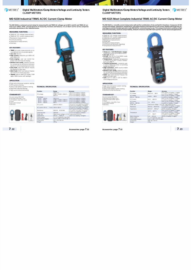
7/25/2019 METREL General Catalog Engl 2015
http://slidepdf.com/reader/full/metrel-general-catalog-engl-2015 112/121
Digital Multimeters/Clamp Meters/Voltage and Continuity Testers Digital Multimeters/Clamp Meters/Voltage and Continuity Testers
7. 22 7. 23Accessories: page 7.32 Accessories: page 7.32
CLAMP METERS
MD 9230 Industrial TRMS AC/DC Current Clamp Meter
TECHNICAL SPECIFICATION:
The MD 9230 is a universal current clamp for measuring DC and TRMS AC voltages up to 600 V and DC and TRMS AC cur-rents up to 1000 A. With a broad spectrum of measuring functions and features, it is an ideal t ool for service companiesand works electricians in the industrial sector.
MEASURING FUNCTIONS:
• TRMS AC, DC voltage measurement;• TRMS AC, DC current measurement;• Resistance measurement;• Continuity testing;• Capacitance measurement;• Diod test.
KEY FEATURES:
• TRMS: accurate measurements on si-nusoidal and non-sinusoidal signals.
• Jaw size: 50 mm.• High current: measures up to 800 A AC
and 1000 A DC.
• Auto-ranging: user can switch be-tween auto and manual ranging.
• Relative zero mode: relative functionfor comparing the difference betweensignals or removing background noise.
• Data Hold: data hold feature freezesthe display for later view.
• MAX Hold: MAX hold feature freezesthe maximum measured value.
• Display: easy to read LCD screen, 3-3/4digits, 4000 counts with backlight.
APPLICATION:
• Solar and wind power systems testing;• UPS systems testing;• Utility scale battery systems testing;• High level industrial testing;• High current electrical testing.
STANDARD SET:
• Current clamp MD 9230• Test lead with probe, 2 pcs• 1.5 V battery, type AAA, 2 pcs• Pouch• Instruction manual• Warranty
Function Range Accuracy
DC voltage400.0 mV,4.000 V, 40.00 V, 400.0 V,600.0 V
±(0.3 % of reading + 3 digits)±(0.5 % of reading + 3 digits)±(1.0 % of reading + 4 digits)
AC voltage 50 Hz … 500 Hz 50 Hz … 60 Hz 60 Hz … 500 Hz 50 Hz … 500 Hz
400.0 mV4.000 V, 40.00 V, 400.0 V4.000 V, 40.00 V, 400.0 V600 V
±(4.0 % of reading + 4 digits)±(1.0 % of reading + 4 digits)±(1.5 % of reading + 4 digits)±(2.0 % of reading + 4 digits)
DC current 400.0 A,1000 A from ±(1.5 % of reading + 4 digits)to ±(5.0 % of reading + 30 digits)
AC current (15 Hz … 1 kHz) 400 A, 800 A from ±(1.5 % of reading + 4 digits)to ±(5.0 % of reading + 30 digits)
Resistance 400.0 Ω … 40.00 MΩfrom ±(0.6 % of reading + 4 digits)to ±(2.0 % of reading + 4 digits)
Continuity test 400.0 Ω ±(1.5 % of reading + 6 digits)Diode test Open-circuit voltage <1.6 VDC, test current 0.4 mACapacitance 500 nF … 3000 µF ±(3.5 % of reading + 6 digits)Power supply 2 x 1.5 V batteries, type AAAOvervolta ge category CAT IV / 300 V; CAT III / 600 VDimensions 227 x 78 x 40 mmWeight 290 g
MD 9225 Most Complete Industrial TRMS AC/DC Current Clamp Meter
TECHNICAL SPECIFICATION:
The MD 9225 is a versatile current clamp meter with perfect combination of size and built-in functions. It measures AC/DCcurrent and voltage, capacitance, temperature, full range resistance and captures In-rush current. Display with large easy-to-read figures and one-handed operation make MD 9225 an extremely easy-to-use. This compact instrument combines a highlevel of functionality, small size and portability. All built-in features make MD 9225 a perfect tool for advanced applications.
MEASURING FUNCTIONS:
• TRMS AC, DC voltage measurement;• TRMS AC, DC current measurement;• Capacitance measurement;• Resistance measurement;• Diode test;• Frequency measurement;• Continuity test (acoustic signaling);
• Temperature measurement.
KEY FEATURES:
• Clamp on + Full Multimeter ranges:measures current up to 400 A AC/DC.
• Jaw size: 26 mm.• In-rush: fast 30 ms Crest-MAX mode
to capture in-rush currents.• Temperature: measures temperature
in Celsius up to 537 °C and in Fahren-heit up to 999 °F.
• Transient protection: it protects userin case of lightning strike or switchingsurge up to 6.5 kV.
• High resolution: 4000 counts enablefast measurements.
• Relative zero mode: relative functionfor comparing the difference betweensignals or removing background noise.
• Hold: data hold function freezes thedisplay for later view.
• Safe: CAT IV / 300 V, CAT III / 600 Vovervoltage protection.
APPLICATION:
• Solar and wind power system testing;• UPS system testing;• Utility scale battery system testing;• Working in small enclosures.
STANDARD SET:• Current clamp MD 9225• Test lead with probe, 2 pcs• Thermocouple probe, type K• Pouch• 1.5 V battery, type AAA, 2 pcs• Instruction manual• Warranty
CLAMP METERS
Function Range Accuracy
DC Voltage 400.0 mV … 600 V From ±(0.3% of reading + 3 digits)to ±(1.0% of reading + 4 digits)
AC Voltage
(50 Hz … 500 Hz)4.000 V … 600 V
From ±(1.0% of reading + 4 digits)
to ±(2.0% of reading + 4 digits)
DC Current 0.0 A … 400.0 AFrom ±(1.0% of reading + 4 digits)to ±(2.5% of reading + 5 digits)
AC Current(40 Hz … 400 Hz)
0 A … 400 AFrom ±(1.0% of reading + 6 digits)to ±(2.5% of reading + 5 digits)
Diode Test Open-circuit voltage < 1.6 V DC, Test current 0.4 mA
Resistance 400.0Ω ... 40.00 MΩFrom ±(0.8% of reading + 6 digits)
to ±(2.0% of reading + 4 digits)Capacitance 500.0 nF … 3000 µF ±(3.5% of reading + 6 digits)
Temperature-20 °C … 537 °C
From ±(2.0% of reading + 3 digits)
to ±(3.0% of reading + 3 digits)
-4 °F … 1000 °FFrom ±(2.0% of reading + 6 digits)to ±(3.0% of reading + 6 digits)
Mains frequency 5 Hz …100 kHz ±(0.5% of reading + 4 digits)Power supply 2 x 1.5 V batteries, type AAAOvervol tage category CAT IV / 300 V, CAT II I / 600 VDimensions 188 x 63 x 40 mmWeight 218 g
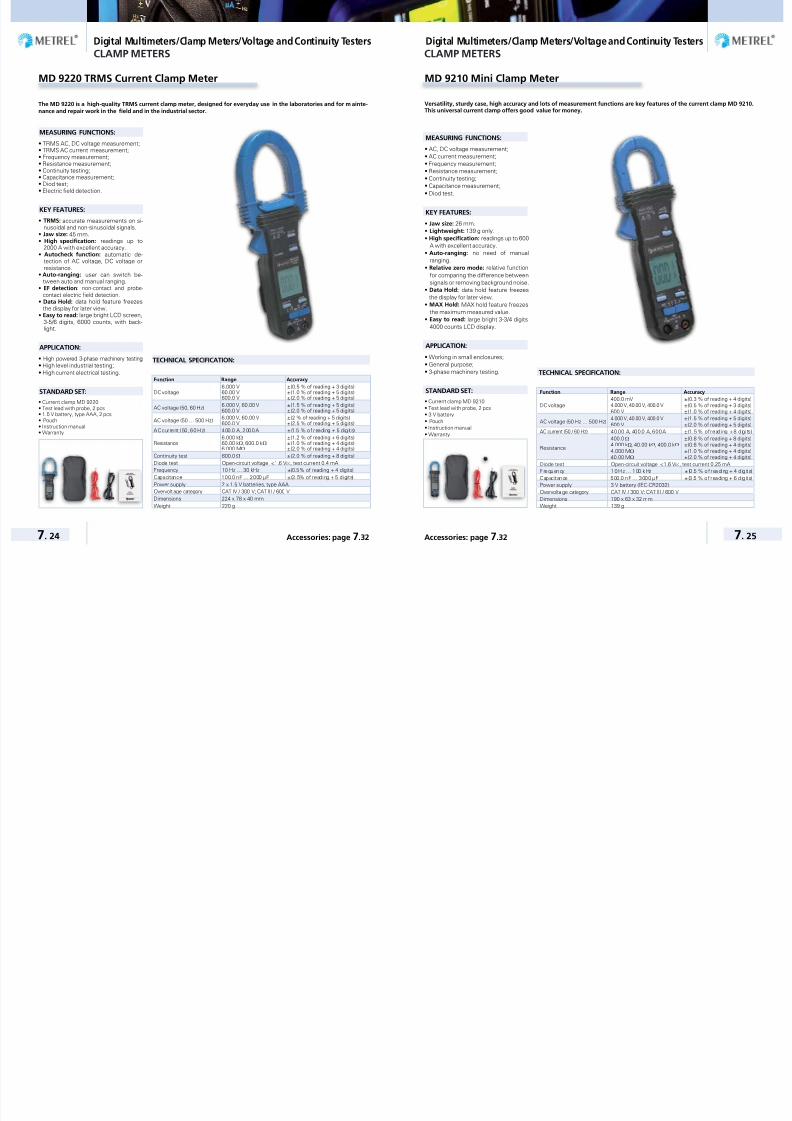
7/25/2019 METREL General Catalog Engl 2015
http://slidepdf.com/reader/full/metrel-general-catalog-engl-2015 113/121
Digital Multimeters/Clamp Meters/Voltage and Continuity Testers Digital Multimeters/Clamp Meters/Voltage and Continuity Testers
7. 24 7. 25Accessories: page 7.32 Accessories: page 7.32
CLAMP METERS
MD 9220 TRMS Current Clamp Meter
The MD 9220 is a high-quality TRMS current clamp meter, designed for everyday use in the laboratories and for m ainte-nance and repair work in the field and in the industrial sector.
MEASURING FUNCTIONS:
• TRMS AC, DC voltage measurement;• TRMS AC current measurement;• Frequency measurement;• Resistance measurement;• Continuity testing;• Capacitance measurement;• Diod test;
• Electric field detection.
KEY FEATURES:
• TRMS: accurate measurements on si-nusoidal and non-sinusoidal signals.
• Jaw size: 45 mm.• High specification: readings up to
2000 A with excellent accuracy.• Autocheck function: automatic de-
tection of AC voltage, DC voltage orresistance.
• Auto-ranging: user can switch be-tween auto and manual ranging.
• EF detection: non-contact and probe-
contact electric field detection.• Data Hold: data hold feature freezes
the display for later view.• Easy to read: large bright LCD screen,
3-5/6 digits, 6000 counts, with back-light.
APPLICATION:
• High powered 3-phase machinery testing;• High level industrial testing;• High current electrical testing.
STANDARD SET:
• Current clamp MD 9220• Test lead with probe, 2 pcs• 1.5 V battery, type AAA, 2 pcs• Pouch• Instruction manual• Warranty
Function Range Accuracy
DC voltage6.000 V60.00 V600.0 V
±(0.5 % of reading + 3 digits)±(1.0 % of reading + 5 digits)±(2.0 % of reading + 5 digits)
AC voltage (50, 60 Hz) 6.000 V, 60.00 V600.0 V
±(1.5 % of reading + 5 digits)±(2.0 % of reading + 5 digits)
AC voltage (50 … 500 Hz) 6.000 V, 60.00 V600.0 V
±(2 % of reading + 5 digits)±(2.5 % of reading + 5 digits)
AC current (50, 60 Hz) 400.0 A, 2000 A ±(1.5 % of reading + 5 digits)
Resistance6.000 kΩ60.00 kΩ, 600.0 kΩ6.000 MΩ
±(1.2 % of reading + 6 digits)±(1.0 % of reading + 4 digits)±(2.0 % of reading + 4 digits)
Continuity test 600.0 Ω ±(2.0 % of reading + 8 digits)Diode test Open-circuit voltage <1.6 VDC, test current 0.4 mAFrequency 10 Hz … 30 kHz ±(0.5% of reading + 4 digits)Capacitance 100.0 nF … 2000 µF ±(3.5% of reading + 5 digits)Power supply 2 x 1.5 V batteries, type AAAOvervolt age category CAT IV / 300 V; CAT III / 600 VDimensions 224 x 78 x 40 mmWeight 220 g
TECHNICAL SPECIFICATION:
CLAMP METERS
MD 9210 Mini Clamp Meter
TECHNICAL SPECIFICATION:
Versatility, sturdy case, high accuracy and lots of measurement functions are key features of the current clamp MD 9210.This universal current clamp offers good value for money.
MEASURING FUNCTIONS:
• AC, DC voltage measurement;• AC current measurement;• Frequency measurement;• Resistance measurement;• Continuity testing;• Capacitance measurement;
• Diod test.
KEY FEATURES:
• Jaw size: 26 mm.• Lightweight: 139 g only.• High specification: readings up to 600
A with excellent accuracy.• Auto-ranging: no need of manual
ranging.• Relative zero mode: relative function
for comparing the difference betweensignals or removing background noise.
• Data Hold: data hold feature freezesthe display for later view.
• MAX Hold: MAX hold feature freezesthe maximum measured value.
• Easy to read: large bright 3-3/4 digits4000 counts LCD display.
APPLICATION:
• Working in small enclosures;• General purpose;• 3-phase machinery testing.
STANDARD SET:
• Current clamp MD 9210• Test lead with probe, 2 pcs• 3 V battery• Pouch• Instruction manual• Warranty
Function Range Accuracy
DC voltage400.0 mV4.000 V, 40.00 V, 400.0 V
600 V
±(0.3 % of reading + 4 digits)±(0.5 % of reading + 3 digits)±(1.0 % of reading + 4 digits)
AC voltage (50 Hz … 500 Hz)4.000 V, 40.00 V, 400.0 V
600 V±(1.5 % of reading + 5 digits)±(2.0 % of reading + 5 digits)
AC current (50 / 60 Hz) 40.00 A, 400.0 A, 600 A ±(1.5 % of reading + 8 digits)
Resistance
400.0Ω4.000 kΩ, 40.00 kΩ, 400.0 kΩ4.000 MΩ
40.00 MΩ
±(0.8 % of reading + 8 digits)±(0.6 % of reading + 4 digits)±(1.0 % of reading + 4 digits)±(2.0 % of reading + 4 digits)
Diode test Open-circuit voltage <1.6 VDC, test current 0.25 mAFrequency 10 Hz … 100 k Hz ± (0 .5 % of rea ding + 4 d ig its)Capac itance 500.0 nF … 3000 µF ±(3.5 % of reading + 6 digits)Power supply 3 V battery (IEC-CR2032)Overvolta ge category CAT IV / 300 V; CAT III / 600 VDimensions 190 x 63 x 32 mmWeight 139 g

7/25/2019 METREL General Catalog Engl 2015
http://slidepdf.com/reader/full/metrel-general-catalog-engl-2015 114/121
Digital Multimeters/Clamp Meters/Voltage and Continuity Testers Digital Multimeters/Clamp Meters/Voltage and Continuity Testers
7. 26 7. 27Accessories: page 7.32 Accessories: page 7.32
Selection Guide for Voltage detectors
Part No.: MD 1155 MD 1055 MD 1160 MD 1060
AC VOLTAGE
Test Range 3 V ... 1000 V 6 V ... 1000 V 0 V ... 690 V 12 V ... 690 V
Operation time Max. 30s Max. 30s − −Response Time <1s <1s <1s <1s
Frequency Range 0 ... 1000 Hz 0 ... 1000 Hz 16 ... 400 Hz 16 ... 400 Hz
DC VOLTAGE
Test Range 4 V ... 1400 V 6 V ... 1000 V 12 V ... 690 V 12 V ... 690 V
Operation time Max. 30s Max. 30s − −
Response Time <1s <1s <1s <1s
RESISTANCE & CONTINUITY TEST
IndicationAcoustical and LCD
indicationAcoustical and LED
indicationAcoustical and LED
indicationAcoustical and LED
Resistance range 0 ... 2 kΩ ± 5% 0 - 50 kΩ − −
Continuity test (Acoustic) Up to 50Ω Up to 50Ω 0 ... 500 kΩ +50% 0 ... 500 kΩ +50%
Test current 80uA 8uA 3.5 µA 3.5 µA
RCD TRIGGER TEST
RCD fault testfor tripping 30 mA RCD
(max 240V)for tripping 30 mA RCD
(max 240V)− −
Phase TESTING
Phase Testing Single-Pole Phase testing Single-Pole Phase testing Single-Pole Phase testing Single-Pole Phase testing
Phase SequenceTwo-Pole Phase
Sequence testingTwo-Pole Phase
Sequence testingTwo-Pole Phase
Sequence testingTwo-Pole Phase
Sequence testing
Phase indication >100 V AC >100 V AC >100 V AC >100 V AC
DISPLAY
Type3 digit, LC display with
backlightLED bargraph LC display LED display
Tolerance 6 V ... 1000 V ±(2% rdg.+ 3D) 12 V, 24 V, 48 V, 120 V,230 V, 400 V, 690 V,1000 V 0 V ... 690 V ± (3% ± 5dgt) 12 V, 24 V, 50 V, 120 V,230 V, 400 V, 690 V
TORCH LAMP LED LED LED LED
SAFETY & PROTECTION
Overload Category CAT IV 1000 V CAT IV 1000 V CAT IV 600 V CAT IV 600 V
Compliant to standardsIEC/EN 61243-3,
DIN VDE 0682-401IEC/EN 61243-3,
DIN VDE 0682-401
IEC/EN 61243-3,DIN VDE 0411,
IEC 61010, GS38
IEC/EN 61243-3,DIN VDE 0411,
IEC 61010, GS38
Protection degreeIP65 For outdoor use:
Water jet and dusttight protection
IP65 For outdoor use:Water jet and dust
tight protection
IP64 For outdoor use:Water jet and dust
tight protection
IP64 For outdoor use:Water jet and dust
tight protection
TEMPERATURE RANGE -10 ... + 55 °C -10 ... + 55 °C -15 ... 55 °C -15 ... 55 °C
POWER SUPPLY
Battery ty pe 2 x 1 ,5 V Ty pe AAA Mic ro 2 x 1 ,5 V Ty pe AAA Mic ro 2 x 1 ,5 V Ty pe AAA Mic ro 2 x 1 ,5 V Ty pe AAA Mic ro
DIMENSIONS
300 x 75 x 20 mm 300 x 75 x 20 mm 240 x 60 x 20 mm 240 x 60 x 20 mm
270 g 270 g 200 g 200 g
VOLTAGE AND CONTINUITY TESTERS
MD 1155 LCD Voltage / Continuity Tester
The MD 1155 is a high-quality voltage / continuity tester designed for t he most demanding duties. With a broad spectrumof measurement functions and CAT IV / 1000 V overvoltage category, the device is suitable for both the industrial sectorand for everyday maintenance and repair practice.
MEASURING FUNCTIONS:
• AC, DC voltage testing;• Phase testing;• Rotary field testing;• Continuity testing;• RCD trip-out test.
KEY FEATURES:
• 3 V … 100 0 V AC TRMS voltage range.
• 4 V ... 1400 V DC voltage range.
• Data hold function.• LCD display with backlight.• Phase rotation measurement.• RCD trip-out test (max. nominal differ-
ential current - 30 mA).• Optical and acoustic continuity test.• LED torch lamp.• Automatic switch off.• CAT IV / 1000 V overvoltage protection.
APPLICATION:
• Mid level electrical testing;• Mid level electronic fault finding;• Field servicing;• General purpose.
STANDARD SET:
• Voltage tester MD 1155• 1.5 V battery, type AAA, 2 pcs• Captive test probe protection• Plastic probe guard (in accordance
with GS38)• Instruction manual• Warranty
TECHNICAL SPECIFICATION:
Function Range
Nominal vo ltage ra nge 3 V … 1000 V AC TRMS (a utomat ic ra nge s elec ti on )Nominal vo ltage range 4 V … 1400 V DC ( automa ti c range se lect ion)Frequency range 0 … 1000 HzResistance range 0 … 2 kΩ
RCD test current 30 mAPhase indication >100 VAC
Phase rotation determination 100 V … 1000 V, 2-poleReaction time < 0.1 sDisplay 3-1/2 digit LCD display with backlightPower supply 2 x 1.5 V batteries, type AAAOvervoltage category CAT IV / 1000 VDimensions 300 x 75 x 20 mmWeight 270 g
VOLTAGE AND CONTINUITY TESTERS

7/25/2019 METREL General Catalog Engl 2015
http://slidepdf.com/reader/full/metrel-general-catalog-engl-2015 115/121
Digital Multimeters/Clamp Meters/Voltage and Continuity Testers Digital Multimeters/Clamp Meters/Voltage and Continuity Testers
7. 28 7. 29Accessories: page 7.32 Accessories: page 7.32
TECHNICAL SPECIFICATION:
The MD 1055 is a multifunction voltage / continuity tester. Because of it’s broad spectrum of measurement functions, it issuitable for use both in the home and in trade and industrial sectors.
MEASURING FUNCTIONS:
• AC, DC voltage testing;• Phase testing;• Rotary field testing;• Continuity testing;• RCD trip-out test.
KEY FEATURES:
• 6 V … 1000 V AC voltage range.
• 6 V … 1000 V DC voltage range.
• Phase rotation measurement.• RCD trip-out test (max. nominal differ-
ential current - 30 mA).• Optical and acoustic continuity test.• LED torch lamp.• CAT IV / 1000 V overvoltage protection.
APPLICATION:
• General purpose;• Electrical testing.
STANDARD SET:
• Voltage tester MD 1055• 1.5 V battery, type AAA, 2 pcs• Captive test probe protection• Plastic probe guard (in accordance with
GS38)• Instruction manual• Warranty
MD 1055 LED Voltage / Continuity Tester
Function Range
Display16 red LEDs for voltage, continuity,polarity and phase rotation measurement
Nominal voltage range12 V, 24 V, 48 V, 120 V, 230 V, 400 V, 690 V, 1000 V(automatic range selection)
Frequency range 0 … 1000 Hz
Resistance range 0 … 50 kΩ
RCD test current 30 mA
Phase indication >100 VAC
Phase rotation determination 100 V … 1000 V, 2-pole
Reaction time < 0.1 s
Power supply 2 x 1.5 V batteries, type AAA
Overvoltage category CAT IV / 1000 V
Dimensions 300 x 75 x 20 mm
Weight 270 g
VOLTAGE AND CONTINUITY TESTERS
MD 1160 LCD Voltage / Continuity Tester
A two-pole voltage detector is a basic tool kit for electricians. High quality rubber construction make this the profes-sional’s choice. Both models support Voltage measurement, Continuity measurement, Single pole test, Phase rotatingfield test and a torch function via a white LED for working in dark areas. The products are built in accordance to t he latestvoltage tester standard EN 61243-3:2010 and are GS approved by TÜV test lab.
MEASURING FUNCTIONS:
• AC, DC voltage testing;
• Phase testing;
• Rotary field testing;
• Continuity testing.
KEY FEATURES:
• Voltage testing u p to 690 V;
• Automatic AC/DC recognition;
• Continuity buzzer and led to indicate re-
sistances below 500 kΩ;
• Phase & Rotating Field Test;
• Auto Power Off;
• LCD display (MD 1160);
• Optical and Acoustic indication of Pro-
tective Extra Low Voltage.
APPLICATION:
• Mid level electrical testing;
• Mid level electronic fault finding;
• Field servicing;
• General purpose.
STANDARD SET:
• Instrument MD 1160-LCD
• Plastic probe guard in accordance
with GS 38, 2 pcs
• 1.5 V battery, type AAA, 2 pcs
• Instruction manual
VOLTAGE AND CONTINUITY TESTERS
TECHNICAL SPECIFICATION:
Function Range
Nominal vo ltage ra nge 0 V … 690 V AC TRMS (a utomat ic ra nge s elec ti on )
Nominal vo ltage range 0 V … 690 V DC (a utomat ic ra nge s elec ti on )
Frequency range 16 … 400 Hz
Continuity test (Acoustic) 0 … 500 kΩ
RCD test current 3.5 mA
Phase indication >100 VAC
Pha se rotat ion determina ti on 2-pole
Reaction time < 0.1 s
Display LC display
Power supply 2 x 1.5 V batteries, type AAA
Overvoltage category CAT IV / 600 V
Dimensions 240 x 60 x 20 mm
Weight 200 g

7/25/2019 METREL General Catalog Engl 2015
http://slidepdf.com/reader/full/metrel-general-catalog-engl-2015 116/121

7/25/2019 METREL General Catalog Engl 2015
http://slidepdf.com/reader/full/metrel-general-catalog-engl-2015 117/121
Digital Multimeters/Clamp Meters/Voltage and Continuity Testers
7. 32 Accessories: page 7.32
PhotoPart
numberDescription Target application
M D 9 0 6 0
M D 9 0 5 0
M D 9 0 4 0
M D 9 0 3 5
M D 9 0 3 0
M D 9 0 2 0
M D 9 0 1 6
M D 9 0 1 5
M D 9 2 5 0
M D 9 2 3 5
M D 1 1 5 5
M D 1 0 5 5
AMD9023
Thermocouple probe,type K
Probe for contact temperature measurement. – – – – –
AMD9024
Adapter forthermocouple probeAMD 9023
Adapter is intended to connect the thermocoupleprobe with a multimeter.
– – – – –
AMD9025
PC Software for MD9015 with RS232cable
Basic downloading software supplied on CD andRS232 communication cable.
– – – – – – – – – –
AMD9050
USB interface setCommunication set contains USB adapter, USB andRS232 drivers and PC software on CD.
– – – – – – – – –
AMD9240
PC interface set forMD 9240
PC interface set enables data transferring to the PC.Set contains optical adapter, cable and PC softwareon CD.
– – – – – – – – – –
AMD9250
PC interface set forMD 9250
PC interface set enables data transferring to the PC.Set contains optical adapter, cable and PC softwareon CD.
– – – – – – – – – – –
AMD1100
Soft carrying bag Small soft bag for storage of the multitester. – – – – – – – – – –
AMD9022
Magnetic HangingStrap
The universal hanger allows you to hang your meteron metal surfaces.
– – – – – – –
Selection Guide for DMM Accessories
Option – Not available
GOOD TO KNOW Variable transformers 8 - 02VARIABLE TRANSFORMERS
Single-phase Built-in Variable Transformers 8 - 04Three-phase Built-in Variable Transformers 8 - 04Motor driven Variable Transformers 8 - 04Desk top Variable Transformers 8 - 05
EQUIPMENT FOR LABORATORIES AND SCHOOLS
Power Supplies 8 - 05
R-L-C Decade 8 - 05
V a r i a b l e t r a n s f o r m e r s / E q u i p m e n t f o r l a b o r a t o r i e s a n d S c h o o l s
P o w e r s u p p l i e s , L a b o r a t o
r y a n d t e s t e q u i p m e n t , V o l t a g e s t a b i l i z e r s ,
H i g h v o l t a g e t e s t s e t , H y d r o g e n e r a t i o n p l a n t s , e t c .
MEASURING INSTRUMENTS AND TESTERS
Variable transformers /
Equipment for laboratories and Schools
CATALOGUE 2015

7/25/2019 METREL General Catalog Engl 2015
http://slidepdf.com/reader/full/metrel-general-catalog-engl-2015 118/121
Variable transformers / Equipment for laboratories and Schools Variable transformers / Equipment for laboratories and Schools
8. 2 8. 3
Variable transformers Variable transformers
GOOD TO KNOW GOOD TO KNOW
METREL is well known producer ofvariable transformers and power sup-plies which are widely accepted inlaboratories, industry, schools.The competitiveness of these productsis based on a good price/performanceratio. They are robust in construction,they have low magnetizing current, lowoperating torque and no distortion or har-monics added. Copper winding is preci-sion wound on a toroidal core. Tradition
with 50 years of experience in continu-ous production, product control, testing,safety, permanent improvements and,customer service are fil rouge in the pro-duction of METREL variable transform-ers. Complete information on variabletransformers and complete instrumentproduct groups of METREL can be foundon www.metrel.si.
METREL variable transformers are avail-able as:• Single or poly phase types;• Autotransformer or insulated variable
transformer;• Manual or motor driven variable trans-
former;• Open / panel mount or enclosed con-
struction;• Air-cooled, optional oil-cooled variable
transformer.
METREL variable transformers providecontinuously adjustable voltage fromzero to 100% or 113% of the line volt-age. Their operation is simple and effi-cient. Cooper wire is wound on a toroi-dal core by using high precision windingmachines. Sliding trace of the windingis properly smoothed to provide low re-sistance and long wearing track for thecarbon brush. Some models are silverplated, providing lower output imped-ance. The core is made of strip-woundoriented silicon steel for low electricallosses and high magnetic densities. Thecoil is insulated from the core by meansof a special insulation support that alsoprevents movement of coil turns. Varia-ble transformers are wound in a mannerto ensure that voltage between the two
turns is small enough to avoid harmfulsparking or excessive heating of shortedturns.
0.1 1 10 100 1000t (min)
100
200
300
400
500
In (%) 600
StandardtrackSilveredtrack
ort duration oading
1 )
1
1
1
METREL variable transformers providean output voltage waveform that is aprecise reproduction of the applied inputvoltage waveform. Slider is mounted onshaft but electrically insulated from it.With a brush holder, it serves also as aheat sink. Only standard METREL vari-able transformers are listed in this cata-logue.
Technical regulationThree general regulations serve as a base
for function, quality and safety of METREL
variable transformers: European Low volt-
age directive 2006/95/EC (2014/35), Interna-
tional standard IEC 61558-1:2005+A1:2009
and IEC 61158-2-14:2012.
ApplicationsMETREL variable transformers are ap-plied to various products or applications
including the following:• Power supplies;• Laboratory and test equipment;• Speed control devices;• Computer peripheral equipment;• Welding controls;• Variable speed devices for large ma-
chinery;• Electroplating and anodising;• High-voltage electronic tube circuits;• Spare supply regulators in broadcast
transmitters;• Voltage stabilizers;• High voltage test set;• Meter test bench;• Hydro generation plants;• Battery chargers;
• DC motor controls;• Plastic blow moulding machines;• Control of furnace transformers;• Lightening regulation;• Laboratory stirrers;• AC, DC brush motors;• High current motorized voltage regula-
tors;• High current plastic plating operations.
TECHNICAL PERFORMANCES:
High reliabilityMETREL variable transformers are prac-tically maintenance free. Long-life opera-tion is assured with:• Precision winding;• Surface forming of winding;• Tight tolerances in preparing sliding
track;• Deep varnishing and baking also for fix-
ing winding structure;• A spring-loaded solid carbon brush.
Power factorPower factor of load has very little effecton the operation of a METREL variabletransformer in the range from 0.5 lag-ging to 0.5 leading. Like any transform-er, the METREL variable transformerreflects the load power factor to the linewith very little change. Only for very lightloads, possibly under 10%, will the lag-ging power factor of the METREL vari-able transformer become significant dueto magnetizing current.
High efficiencyMETREL variable transformers havelow electrical losses under all load con-ditions. Efficiency is 98.5 percent atmaximum output voltage selected. Thisefficiency remains high, even at greatlyreduced load voltage.
Ambient temperatureMETREL variable transformers are de-signed for continuous operation in ambi-ent of 0 °C to 40 °C, at full rated load.When operated above 40 °C, the outputpower must be derated in accordancewith diagram 1. For example, when op-erating model HSH 230/4 in a 60 °C am-bient, rated output current would be: 70% x 4 A = 2.8 A.
.
20 30 40 50 60 70 80 100
20
40
80
100
120
60
90 Ta C( )
In (%)Loading versus ambient temperature
Standard track
Silvered track
1 )
1
1
1
o
FrequencyAll METREL variable transformers aredesigned for operation at 50/400 Hz.They may be operated at higher frequen-cies, without derating, however regula-tion becomes poorer. Units listed for 230V operations may be applied on 115 Vat 25 Hz, however rated currents remainthe same.
Linear output voltageMETREL variable transformers have theadvantage of providing output voltagethat varies linearly in proportion to theangle of rotation of the output voltageselector. Because of the large numberof increments of output voltage selec-tion with the slider, the output voltage ispractically steeples.
.1 1 1 1 1 1
)
l
20 40 60 80 120 Uo/Uin%( )
20
40
80
100
60
Udn (%)
100
120ormazed votage drop o
∆Uo/ ∆Uo max for autotransformer / Uo max = Uin ∆Uo/ ∆Uo max for autotransformer / Uo max > Uin ∆Uo/ ∆Uo (at Uo = Uin) for separate secondary ∆Uo/Uo for separate secondary ∆Uo/Uo for autotransformer / Uo max = Uin ∆Uo/Uo for autotransformer / Uo max > Uin
Installation guidelinesFor safety and reliable operation of MET-REL variable transformers the followingrequirements need to be fulfilled:• good venting;• appropriate wiring;
• over current protection;• avoiding corrosive, high humidity and
dust places or protection against theseenvironmental conditions;
• preventing short circuits on axis;• appropriate design and construction of
equipment with built-in variable trans-formers.
Venting of power devices reduces theirheating and thus rated performances
can be applied. Power lines must havehigh enough cross-section, be fixedand secured with good contact to pre-vent overheating and additional voltagedrops. Primary overcurrent breakingdevice must be properly selected anduse of load protection fuses is recom-mended. Fuses / residual circuit break-ers (RCD) prevent excessive heating dueto overload and prevent fire generationas a result of overheating.
Regardless if the variable transformersare designed for harsh environment, itis best for reliable operation and longlifetime to keep them in non-aggressiveenvironment. The axis is on one sideconnected to metal base. If the otherside of axis is electrically connected tothe same base (through the housing),this will present a short circuit coil of thetransformer with increasing power con-sumption, overheating, and even gen-erating high leakage currents and straymagnetic fields.
It is important that the brushes are notleaving in one spot for extended peri-ods to avoid gradually increase contactresistance and eventual overheating anddamage of the variable transformer unit.
OPTIONS:
Parallel connectionsMETREL has a solution for parallelingtwo single-phase transformers. Outputcurrent can be doubled by using the bal-ancing choke and mechanical parallelingof sliders on common shaft.
Serial connectionsSerial connection is intended for appli-
cation of variable transformers in instal-lations with higher input voltage thanrated. Two variable transformers of thesame type are connected in series andenable operation with double voltage ofrated for one.
Dual voltage tap slidesThis possibility enables generating vari-able differential voltage with the same oropposite phase related to input voltage.
Typical applications are boosting regula-tors.
Shaft modificationsThe shaft provided with each model ac-commodates the METREL transformer’svoltage selector knob when mountedon panels not exceeding the thicknessshown in dimension data. Modificationto the shaft, either in length or end di-ameter, is available for both manual andmotor-operated units.
Product groupsa) Open variable transformer types (sub-assemblies for panel mount or otherbuilt-in equipment) HSG; HST; HTG;HSM; HTM with Accessories (Buttons,Scales, Motor drives).
b) Desk top variable transformer types(HSN, HTN).
c) Power supplies (MA 4804, MA 4852,MA 4853).
Technical specification
F re qu en cy ra ng e: 5 0 H z . .. 4 00 Hz
Mechanical angle:340, core size up to M200320, other core sizes
Protection class: I
Pollution degree: 2
P ro te ct io n d eg re e: I P 2 0
Alt it ude (oper at ion) : 2000 m
Test voltage(input to metallicaccessible parts):
2500 VAC RMS, 50 Hz, 2 s
Test voltage(input/output, HST):
4000 VAC RMS, 50 Hz, 2 s
Operating temperaturerange:
-5 °C ... 40°C
Operating humidityrange:
90 % RH (40 °C),non-condensing
Storage temperaturerange:
-15 °C ... 70 °C

7/25/2019 METREL General Catalog Engl 2015
http://slidepdf.com/reader/full/metrel-general-catalog-engl-2015 119/121
Variable transformers / Equipment for laboratories and Schools Variable transformers / Equipment for laboratories and Schools
8. 4 8. 5
Motor driven3-phase Built-in1-phase Built-in Desk top Power Supplies R-L-C Decade
HSG - Autotransformers
The HSG series voltage transformersare often built in test equipment or per-manent installations. Output voltage iscontrolled with a large, slip-protectedknob. Output voltage is increased lin-early as the knob is turned clockwise.The user is required to add adequateexternal over-current protection devicelike fuse or circuit breaker. All modelsare suitable for 50 Hz / 400 Hz frequencyrange. Single- and three-phase modelsare available with various current ratings.Output voltage is precisely controlled.Autotransformer design allows optionalvoltage boost. Because of demandingapplications all Metrel variacs are de-signed to exhibit superior resistanceto high temperature, humidity and me-chanical shocks/vibrations. Used in hard-wired, permanent installations whereveroperational or performance points needto be varied.
Technical specification
1-phase: HSG 230 HSG 260Input voltage: 230 V 230 V
Out pu t v ol ta ge : 0 V . . . 230 V 0 V . . . 260 V
Current:* 1 A ... 32 A 0.8 A ... 30 A
P ow er : 2 30 VA .. . 7 36 0 VA 2 08 VA .. . 7 80 0 VA
* Maximum current range depends on model type
HST - Separating transformers
Variable, coupled with insulation trans-formers are utilized for personnel safetyin addition to provide variable voltagesfor testing purposes. In general they areequally suitable for any of the testing,engineering or control function like or-dinary variacs based on autotransformerdesign. Additionally they can isolate sen-sitive equipment from interference andground noise.
HTG - Autotransformers
METREL three-phase transformers aresuitable for connection to either delta orstar connected incoming power sourcesor loads. They are always star connectedand have a neutral connection accessi-ble. A common shaft rotates all outputvoltage sliders in parallel. 3-phase METREL transformers with3-wire connection to 3-phase supply sys-tem can be used to feed 3-wire, 3-phasebalanced loads. In this case the commonconnection (or “virtual neutral”) of theMETREL unit should not be used. Lessthan 10% of rated current of variabletransformers flowing into virtual neutralwould keep unbalance of three-phaseoutput in reasonable limits.
With a three phase, 4-wire system in-put, the system neutral should be solidlyconnected to the common or “neutral”point of the METREL unit. This will pre-
vent neutral shift and possible damageor failure of the unit. Full-range voltagecontrol cannot be obtained from a three-phase METREL unit consisting of threesingle-phase units connected in closeddelta. Outside the factory, it is not prac-tical to convert multiple single-phasemodels to balanced three-phase applica-tions because of associated mechanicalproblems.
Technical specification
3-phase: HTG 400 HTG 450
Input voltage: 400 V 400 V
Out pu t v ol ta ge : 0 V . . . 400 V 0 V . . . 450 V
Current:* 1 A ... 32 A 0.8 A ... 30 A
Power:690 VA ... 22080VA
624 VA ... 23400VA
* Maximum current range depends on model type
HSM 1-phase and HTM 3-phase
METREL motor-operated units dif-fer from manual types primarily in themeans used to rotate the shaft to varyoutput voltage. A synchronous motor isused to position the slider. The motor isreversible by means of a SPDT switch(not supplied) and operates on 230 V, 50
/ 400 Hz. Integrated limit switches pre-vent overriding the winding edges.
Typical methods for controlling METRELmotor-operated units include:• Manual increase/decrease switch con-
sists of either momentary-contact push-button or lever-type toggle switch.
• Relays and contactors control the in-crease/decrease power to the motor asa result of low-level signals from externalcircuitry. Example: photoelectric cells orthermostat signals can provide the input.
• Process control instrumentation canbe used for closed-loop, precise con-trol, and more sophisticated circuitry toprovide the raise-fall switching for themotor.
Motor operating time refers to the num-ber of seconds for the motor to traverseits full range in one direction. METRELtransformers have standard 23 s motoroperating time. Other motor operatingtimes are optional.
Technical specification
1-phase: HSM 230 HSM 260
Input voltage: 230 V 230 V
Out pu t v ol ta ge : 0 V . . . 230 V 0 V . . . 260 V
Current:* 3 A ... 32 A 2.5 A ... 30 A
P ow er : 6 90 VA .. . 7 36 0 V A 6 50 VA .. . 7 80 0 VA
3-phase: HTM 400 HTM 450
Input voltage: 400 V 400 V
Out pu t v ol ta ge : 0 V . . . 400 V 0 V . . . 450 V
Current:* 3 A ... 32 A 2.5 A ... 30 A
Power: 2070 VA ... 22080 VA 1930 VA ... 23400 VA
* Maximum current range depends on model type
HSN 1-phase and HTN 3-phase
The HSN and HTN series voltage trans-formers are fully housed, thus providingprotection from physical accidents, andother hazards. Generally they are usedwherever adjustable AC voltage is re-quired. Output voltage is precisely con-trolled.
Output voltage is controlled with alarge, slip-protected knob. Output volt-age is increased linearly as the knobis turned clockwise. All models areequipped with power cord, illuminatedon/off switch and external PE terminaland optional with appropriate plug con-nector. They are marked with outputvoltage in volts (corresponding to nomi-nal input voltage).
They can be conveniently movedaround laboratory, production or equip-ment service area to provide adjustable
voltage.All models are suitable for 50 Hz / 400Hz frequency range. Single- and three-phase models are available with variouscurrent ratings.
Technical specification
1-phase: HSN 260
I npu t vo lt ag e: 2 30 V
Out pu t vo lt age: 0 V . .. 260 V
Current:* 4.5 A ... 30 A
Power: 1170 VA ... 7800 VA
3-phase: HTN 450
I npu t vo lt ag e: 4 00 V
Out pu t vo lt age: 0 V . .. 450 V
Current:* 8 A ... 30 A
Power: 6240 VA ... 23400 VA
* Maximum current range depends on model type
MA 4804, MA 4852 and MA 4853
The MA 4804, MA 4852 and MA 4853are power supply units with the built-invariable transformers permiting a con-tinuous voltage adjustment within thelimits of declared specifications.
The transformers have separate primaryand secondary windings resulting in gal-vanic isolation of the mains circuit fromoutput circuit. This is frequent require-ment for energizing specific electricaldevices.
The power supply units are equippedwith V-meter and A-meter, which allowa permanent control over output voltageand current. They are overload-protectedwith a circuit-breaker which disconnectsthe secondary circuits when a short-cir-cuit condition occurs at the output.
Field ApplicationThe MA 4804, MA 4852 and MA 4853power supply units are used in electron-ic industry (electrical and control labs), in
service workshops, in technical educa-tion, etc., briefly everywhere adjustablesupply voltage is needed, or where fortechnical or safety reasons the powersupply source has to be galvanically in-sulated from the mains. Test voltage of4 kV AC. rms between input and outputenables using the units in CAT III / 300 Venvironment.
Technical specification
Part No. HSM 230 HSM 260 HSM 260
Power supply: 230 V 230 V 230 V
Outputvoltage:ACDC
0 V ... 260 V 0 V ... 33 V0 V ... 46 V
0 V ... 33 V0 V ... 46 V
Permissiblepermanentcurrent:
3.1 A 6 A 6 A
* Maximum current range depends on model type
MA 2405, MA 2705 and MA 2115
MA 2405 Decade capacitor is intendedfor all application areas where capaci-tance variation/selection by hand is re-quired. It is all passive electric devicehoused in metallic case and with internalguarding. It consists of 3 decades forselection of the capacitance in range of100 pF up to 100 nF. Set value is directlyvisible on decade’s dials. MA 2405 Dec-ade Capacitor uses high quality polypro-pylene capacitors providing accuracy of5 %.Very good DC insulation resistanceof the capacitors enables the applicationalso in DC circuits, insulation materialsalso provide low dissipation factor at thefrequencies of 500 kHz and up.
MA 2705 Decade inductance is in-tended for all application areas whereinductance variation/selection by handis required. It is passive electric devicehoused in metallic case. It consists of3 decades for selection of the induct-ance in range of 0 mH up to 999 mH.Set
value is directly visible on decade’s dials.MA 2705 Decade inductance uses fer-rite chokes providing accuracy of 5 % at50% of rated current.
MA 2115 and MA 2115 S Decade resis-tors are intended for all application areaswhere resistances variation/selection byhand are required. It is passive electricdevice housed in metallic case. Eachconsist of 7 decades with each own ro-tary switch with range multiplier from 0to 9, and ∞. Safety 4 mm sockets areconnected to each resistance chain thatit could be individually accessible. It isalso possible to split resistance chaininto two or more independent insulatedgroups by selection of rotary switch po-sition ∞.
VARIABLE TRANSFORMERS EQUIPMENT FOR LABORATORIES AND SCHOOLS

7/25/2019 METREL General Catalog Engl 2015
http://slidepdf.com/reader/full/metrel-general-catalog-engl-2015 120/121
Variable transformers / Equipment for laboratories and Schools Variable transformers / Equipment for laboratories and Schools
8. 6 8. 7
Notes Notes

7/25/2019 METREL General Catalog Engl 2015
http://slidepdf.com/reader/full/metrel-general-catalog-engl-2015 121/121
METREL d.d.Measuring and Regulation Equipment ManufacturerLjubljanska 77, SI-1354 Horjul, SloveniaT +386 (0)1 75 58 200, F +386 (0)1 75 49 [email protected], www.metrel.si