eurotestcombo mi 3125 short instructions - · pdf file2.2.6 line impedance - (phase-neutral,...
TRANSCRIPT
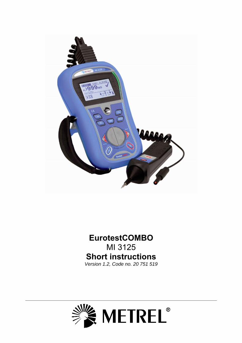
EurotestCOMBO MI 3125
Short instructions Version 1.2, Code no. 20 751 519
2
Distributor: Manufacturer: METREL d.d. Ljubljanska cesta 77 1354 Horjul Slovenia web site: http://www.metrel.si e-mail: [email protected]
Mark on your equipment certifies that this equipment meets the requirements of the EU (European Union) concerning safety and electromagnetic compatibility regulations
© 2010 METREL This manual belongs to instrument HW ver. 1.0 No part of this publication may be reproduced or utilized in any form or by any means without permission in writing from METREL.
MI 3125 EurotestCOMBO Table of contents
3
Table of contents 1 Start-up guide .........................................................................................................4
1.1 Safety and operational considerations ..............................................................4 1.2 Instrument description - Front and connector panel ..........................................5 1.3 Instrument description - Meaning of symbols ....................................................5 1.4 Function selector switch and instrument display ...............................................7 1.5 Battery handling ................................................................................................7 1.6 Maintenance......................................................................................................8
1.6.1 Replacing fuses..........................................................................................8 1.7 Warranty & Repairs ...........................................................................................9 1.8 Contact Metrel UK ...........................................................................................10
2 Quick-test guide ...................................................................................................11 2.1 Null the leads...................................................................................................11 2.2 Measurements.................................................................................................12
2.2.1 Online Voltage and frequency / Phase sequence - AC Voltage measurement and frequency measurements, phase sequence ...............12
2.2.2 Insulation resistance - For testing the MΩ value of the insulation between wires...........................................................................................14
2.2.3 Continuity for testing resistance of earth conductors and equipotential bonding ...............................................................................16
2.2.4 RCD testing - 3 functions for testing RCDs. .............................................18 2.2.5 Loop - Fault loop impedance....................................................................20 2.2.6 Line impedance - (phase-neutral, phase-phase)......................................22
MI 3125 EurotestCOMBO Start-up guide
4
1 Start-up guide 1.1 Safety and operational considerations Warnings
This document is not a supplement to the Instruction manual! Before using the instrument read the instruction manual carefully otherwise use of
the instrument may be dangerous for the operator, for the instrument or for equipment under test!
Symbol on the instrument means »Read the Instruction manual with special care«. The symbol requires an action!
If the test equipment is used in a manner not specified in instruction manual the protection provided by the equipment may be impaired!
Do not use the instrument or any of the accessories if any damage is noticed! In case a fuse has blown follow the instructions in instruction manual to replace it! Consider all generally known precautions in order to avoid risk of electric shock
while dealing with hazardous voltages! Do not use the instrument in supply systems with voltages higher than 550 V! Service intervention or adjustment procedure is only authorized to be carried out
by competent people, authorized and trained by Metrel! Use only standard or optional test accessories supplied by your distributor! Consider that older and some of new optional test accessories could be
compatible with this instrument but only meet a CAT III / 300 V overvoltage category! If this is the case, this implies that the maximum voltage allowed between test terminals and ground is 300 V!
The instrument is supplied with rechargeable Ni-MH battery cells. These battery cells should only be replaced with the same type (as defined on the battery placement label and in the instruction manual). Do not use standard alkaline battery cells while the power supply adapter is connected otherwise they may explode!
Hazardous voltages can exist inside the instrument. Disconnect all test leads, remove the power supply cable and switch off the instrument before removing the battery compartment cover. All normal safety precautions must be taken in order to avoid the risk of electric shock when working on electrical installations!
MI 3125 EurotestCOMBO Start-up guide
5
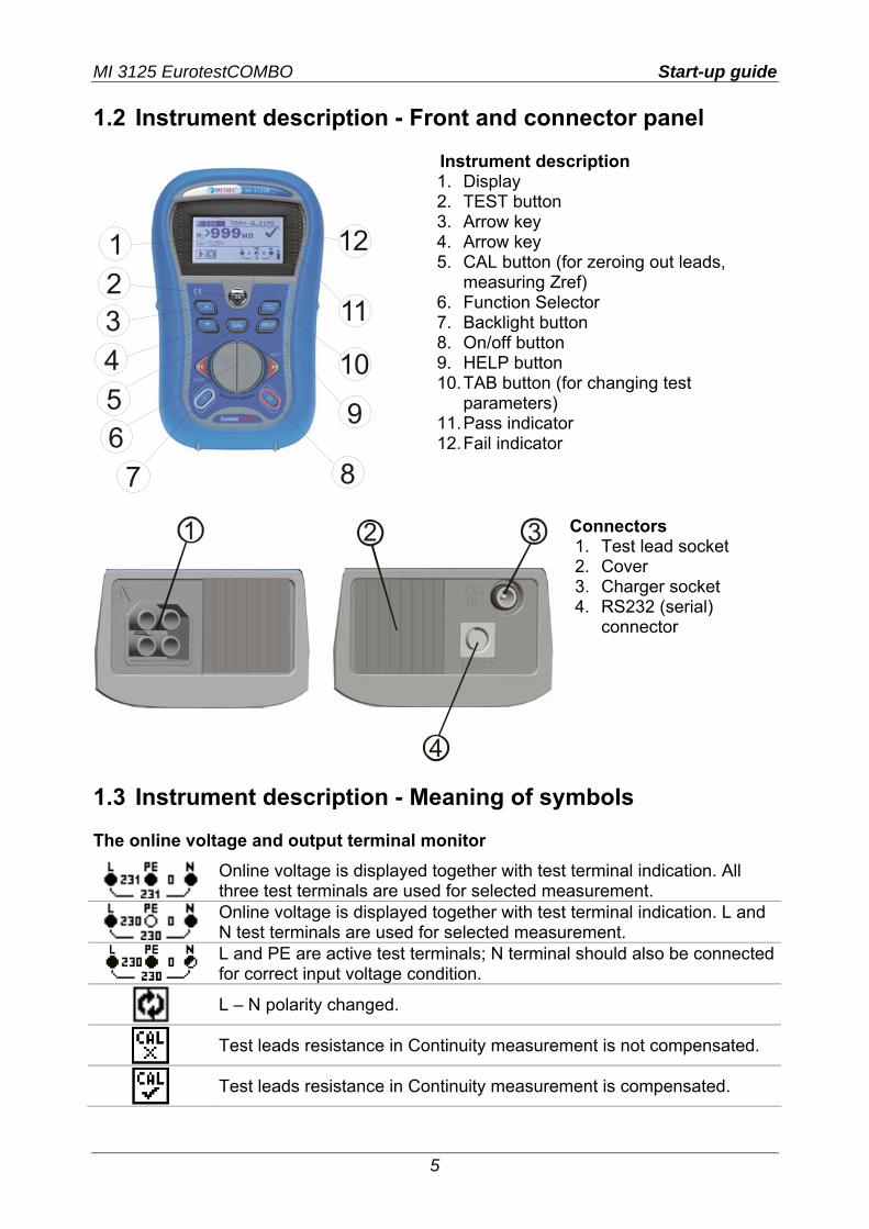
1.2 Instrument description - Front and connector panel
8
9
10
11
12
7654321
Instrument description 1. Display 2. TEST button 3. Arrow key 4. Arrow key 5. CAL button (for zeroing out leads,
measuring Zref) 6. Function Selector 7. Backlight button 8. On/off button 9. HELP button 10. TAB button (for changing test
parameters) 11. Pass indicator 12. Fail indicator
1 2 3
4
Connectors 1. Test lead socket 2. Cover 3. Charger socket 4. RS232 (serial)
connector
1.3 Instrument description - Meaning of symbols The online voltage and output terminal monitor
Online voltage is displayed together with test terminal indication. All three test terminals are used for selected measurement.
Online voltage is displayed together with test terminal indication. L and N test terminals are used for selected measurement.
L and PE are active test terminals; N terminal should also be connected for correct input voltage condition.
L – N polarity changed.
Test leads resistance in Continuity measurement is not compensated.
Test leads resistance in Continuity measurement is compensated.
MI 3125 EurotestCOMBO Start-up guide
6
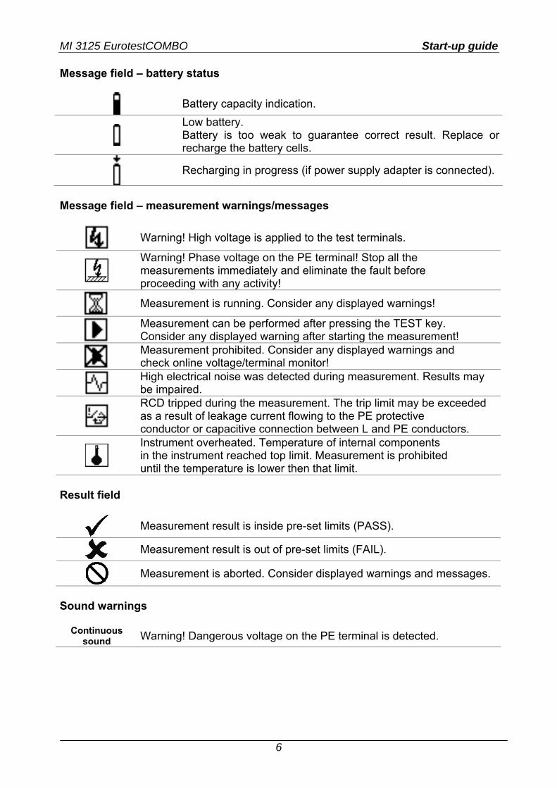
Message field – battery status
Battery capacity indication.
Low battery. Battery is too weak to guarantee correct result. Replace or recharge the battery cells.
Recharging in progress (if power supply adapter is connected).
Message field – measurement warnings/messages
Warning! High voltage is applied to the test terminals.
Warning! Phase voltage on the PE terminal! Stop all the measurements immediately and eliminate the fault before proceeding with any activity!
Measurement is running. Consider any displayed warnings!
Measurement can be performed after pressing the TEST key. Consider any displayed warning after starting the measurement!
Measurement prohibited. Consider any displayed warnings and check online voltage/terminal monitor!
High electrical noise was detected during measurement. Results may be impaired.
RCD tripped during the measurement. The trip limit may be exceeded as a result of leakage current flowing to the PE protective conductor or capacitive connection between L and PE conductors.
Instrument overheated. Temperature of internal components in the instrument reached top limit. Measurement is prohibited until the temperature is lower then that limit.
Result field
Measurement result is inside pre-set limits (PASS).
Measurement result is out of pre-set limits (FAIL).
Measurement is aborted. Consider displayed warnings and messages.
Sound warnings
Continuous sound Warning! Dangerous voltage on the PE terminal is detected.
MI 3125 EurotestCOMBO Start-up guide
7
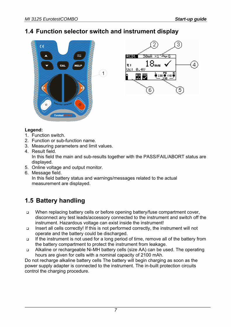
1.4 Function selector switch and instrument display
1
Legend: 1. Function switch. 2. Function or sub-function name. 3. Measuring parameters and limit values. 4. Result field.
In this field the main and sub-results together with the PASS/FAIL/ABORT status are displayed.
5. Online voltage and output monitor. 6. Message field.
In this field battery status and warnings/messages related to the actual measurement are displayed.
1.5 Battery handling
When replacing battery cells or before opening battery/fuse compartment cover, disconnect any test leads/accessory connected to the instrument and switch off the instrument. Hazardous voltage can exist inside the instrument!
Insert all cells correctly! If this is not performed correctly, the instrument will not operate and the battery could be discharged.
If the instrument is not used for a long period of time, remove all of the battery from the battery compartment to protect the instrument from leakage.
Alkaline or rechargeable Ni-MH battery cells (size AA) can be used. The operating hours are given for cells with a nominal capacity of 2100 mAh.
Do not recharge alkaline battery cells The battery will begin charging as soon as the power supply adapter is connected to the instrument. The in-built protection circuits control the charging procedure.
MI 3125 EurotestCOMBO Start-up guide
8
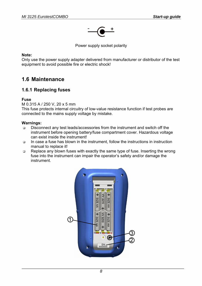
Power supply socket polarity Note: Only use the power supply adapter delivered from manufacturer or distributor of the test equipment to avoid possible fire or electric shock! 1.6 Maintenance 1.6.1 Replacing fuses Fuse M 0.315 A / 250 V, 20 x 5 mm This fuse protects internal circuitry of low-value resistance function if test probes are connected to the mains supply voltage by mistake. Warnings:
Disconnect any test leads/accessories from the instrument and switch off the instrument before opening battery/fuse compartment cover. Hazardous voltage can exist inside the instrument!
In case a fuse has blown in the instrument, follow the instructions in instruction manual to replace it!
Replace any blown fuses with exactly the same type of fuse. Inserting the wrong fuse into the instrument can impair the operator’s safety and/or damage the instrument.
MI 3125 EurotestCOMBO Start-up guide
9
1.7 Warranty & Repairs Metrel UK’s instruments have a three year warranty against defects in materials or workmanship. Accessories and other supplementary products have a one year warranty against defects in material or workmanship. Any potentially defective items should be returned to Metrel accompanied by information regarding the faults that was incurred. It is recommended that any defective equipment is sent back to Metrel via the wholesaler from which the product was purchased. All defective products will be replaced or repaired within policy period. For these items, a full refund will only be issued if a sufficient replacement is not available. Any shipping / return-shipping costs are not refundable. Metrel UK shall not be held liable for any loss or damage resulting from the use or performance of the products. In no event shall Metrel UK be liable to the customer or its customers for any special, indirect, incidental, exemplary or punitive damages resulting from loss of use, interruption of business or loss of profits, even if Metrel UK has been advised of the possibility of such damages. If the customer’s unit is out of warranty but needs repairs a quote for repair will be provided via the wholesaler through which the instrument was sent in. Notes
Any unauthorized repair or calibration of the instrument will infringe the product’s warranty.
All sales are subject to Metrel UK’s Standard Terms and Conditions, a full copy of which is available Metrel UK’s office. Metrel UK reserves the right to change the conditions at any time. Any typographical, clerical or other error or omission in any sales literature, quotation, price list, acceptance of offer, invoice or other documentation or information issued by Metrel UK shall be subject to correction without any liability on the part of the customer.
Specifications and designs of goods are subject to change by Metrel UK at any time without notice to the customer. Metrel UK reserves the right to make any changes in the specification of goods which are required to conform with any applicable statutory or EC requirements or, where goods are to be supplied to Metrel UK’s specification, which do not materially affect their quality or performance.
If a condition was found to be invalid or void it would not affect the overall validity of the remainder of the conditions;
Metrel UK are excluded from liability for any delays or failure to comply, where the reason is beyond Metrel UK’s control;
No order which has been accepted by Metrel UK may be cancelled by the customer except with the agreement in writing of Metrel UK and on terms that the customer shall indemnify Metrel UK in full against all loss (including loss of profit), costs (including the cost of all labour and materials used), damages, charges and expenses incurred by Metrel UK as a result of cancellation. The minimum charge for such cancellation will be 25 % of the total value of the goods ordered.
MI 3125 EurotestCOMBO Start-up guide
10
1.8 Contact Metrel UK Metrel UK Unit 1, Hopton House, Ripley Drive Normanton Industrial Estate Normanton, West Yorkshire WF6 1QT Tel.:+44/ (0) 1924 24 50 00 Fax: +44/(0) 1924 24 50 07 E-mail: [email protected] Web: www.metrel.co.uk Update your meter Metrel offers a service of updating your software of firmware to the latest developments. Register on www.metrel.co.uk to receive updates of PC SW and firmware of the meters. Calibrate your Meter Metrel offers a calibration service of all Metrel equipment. Contact Metrel UK on 01924 245000 and ask for the calibrations department. Repair Metrel offers a repair service of all Metrel equipment. Contact Metrel UK on 01924 245000 and ask for the repairs department. Ask a technical question Metrel offers a Technical Advice Line every Mon-Thu from 8:00 a.m. till 5.00 p.m. and Fridays from 8:00 a.m. till 4 p.m.. Get training on Metrel meters Metrel offers training on site or at the office subject to a charge.
MI 3125 EurotestCOMBO Quick-test guide
11
2 Quick-test guide
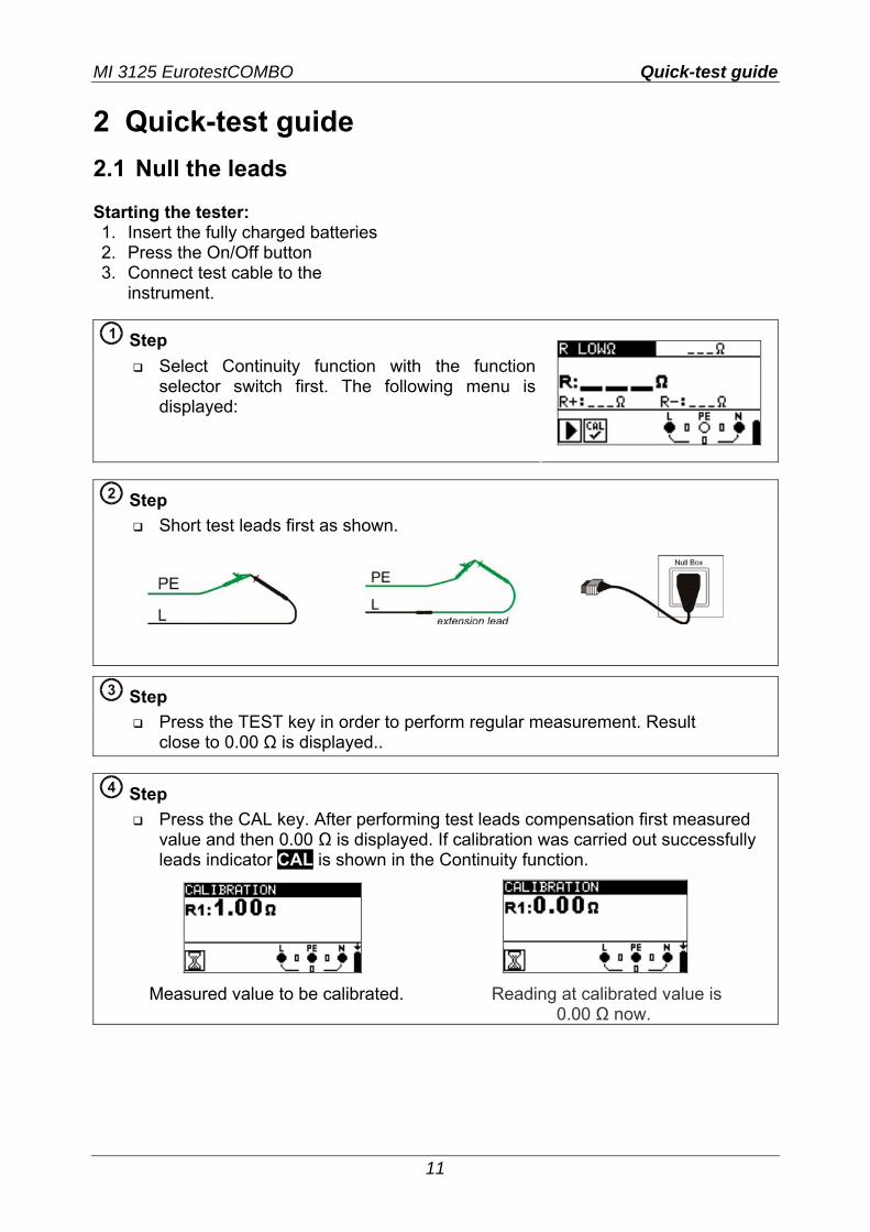
2.1 Null the leads Starting the tester: 1. Insert the fully charged batteries 2. Press the On/Off button 3. Connect test cable to the
instrument.
1 Step
Select Continuity function with the function selector switch first. The following menu is displayed:
2 Step
Short test leads first as shown.
3 Step
Press the TEST key in order to perform regular measurement. Result close to 0.00 Ω is displayed..
4 Step
Press the CAL key. After performing test leads compensation first measured value and then 0.00 Ω is displayed. If calibration was carried out successfully leads indicator CAL is shown in the Continuity function.
Measured value to be calibrated. Reading at calibrated value is 0.00 Ω now.
MI 3125 EurotestCOMBO Quick-test guide
12
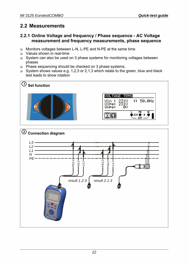
2.2 Measurements 2.2.1 Online Voltage and frequency / Phase sequence - AC Voltage
measurement and frequency measurements, phase sequence
Monitors voltages between L-N, L-PE and N-PE at the same time Values shown in real-time System can also be used on 3 phase systems for monitoring voltages between
phases Phase sequencing should be checked on 3 phase systems. System shows values e.g. 1,2,3 or 2,1,3 which relate to the green, blue and black
test leads to show rotation
1 Set function
2 Connection diagram
L3L2L1NPE
N/L
2
N/L
2
L/L1
L/L1
PE/
L3
PE/
L3
result 1.2.3 result 2.1.3
MI 3125 EurotestCOMBO Quick-test guide
13
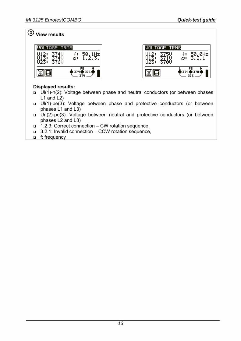
3 View results
Displayed results: Ul(1)-n(2): Voltage between phase and neutral conductors (or between phases
L1 and L2) Ul(1)-pe(3): Voltage between phase and protective conductors (or between
phases L1 and L3) Un(2)-pe(3): Voltage between neutral and protective conductors (or between
phases L2 and L3) 1.2.3: Correct connection – CW rotation sequence, 3.2.1: Invalid connection – CCW rotation sequence, f: frequency

MI 3125 EurotestCOMBO Quick-test guide
14
2.2.2 Insulation resistance - For testing the MΩ value of the insulation between wires
Test voltages can be changed from 50 V to 1000 V. Selectable limits can be set “on-screen” for quick evaluation of results.
1 Set function
2 Set parameters and limits
Nominal test voltage (50 VDC ÷ 1000 VDC) Low limit resistance Ω sets limit off, 0.01 MΩ ÷ 200 MΩ
3 Connection diagram
4 Press and hold the TEST
key until result has stabilised.
MI 3125 EurotestCOMBO Quick-test guide
15
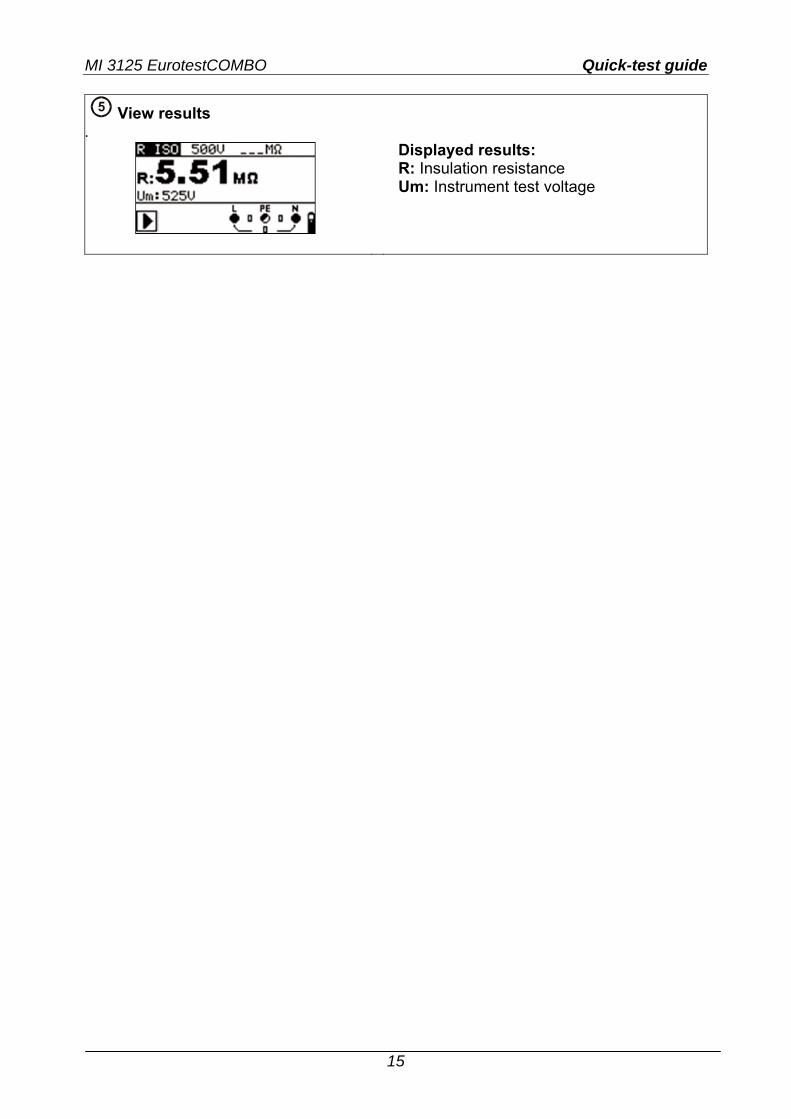
5 View results
.
Displayed results: R: Insulation resistance Um: Instrument test voltage

MI 3125 EurotestCOMBO Quick-test guide
16
2.2.3 Continuity for testing resistance of earth conductors and equipotential bonding
A limit can be set in order to automatically evaluate results. Results below the limit
will be marked with a while results above the limit will be marked with a .
1 Set function
2 Set parameters and limits
High limit resistance Ω sets limit off, 0.1 Ω ÷ 20.0 Ω]
3 Connection diagrams
r1
rN
MI 3125 EurotestCOMBO Quick-test guide
17
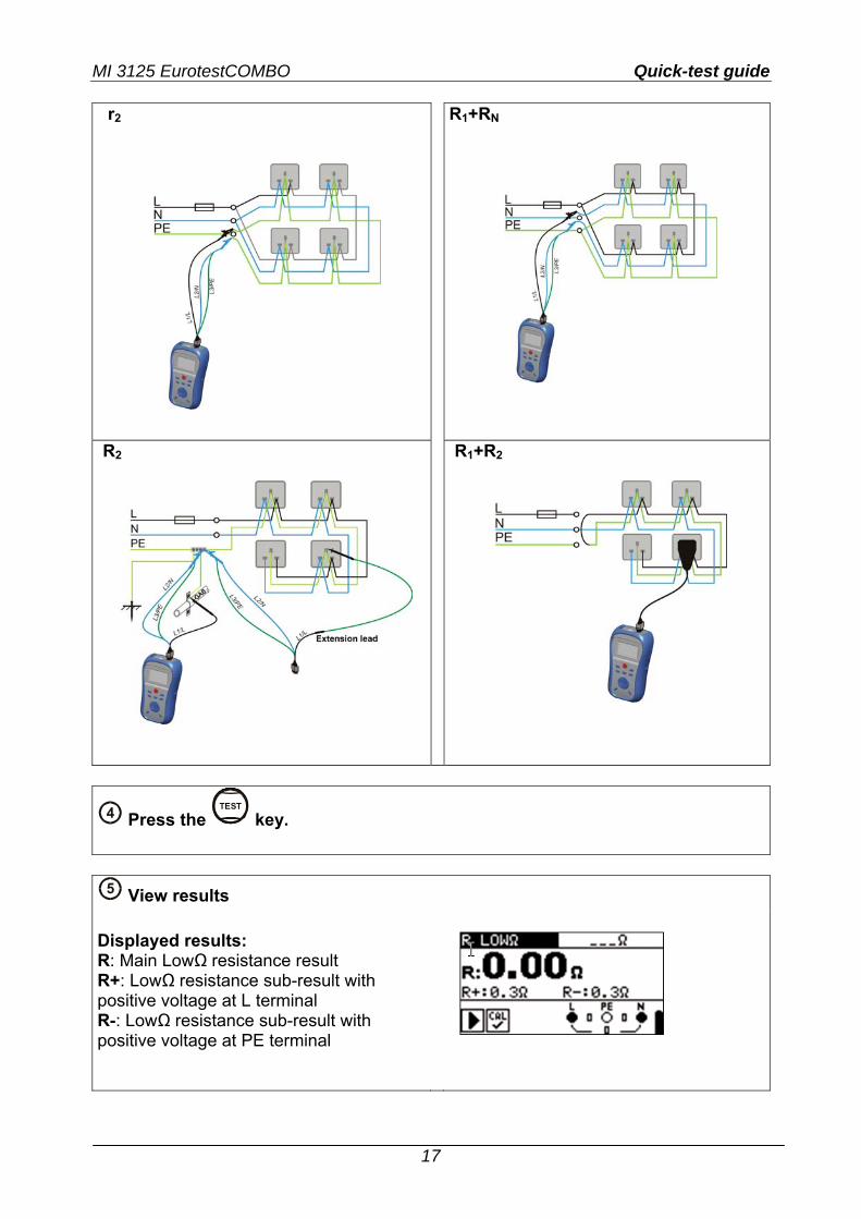
r2
R1+RN
R2
R1+R2
4 Press the TEST
key.
5 View results
Displayed results: R: Main LowΩ resistance result R+: LowΩ resistance sub-result with positive voltage at L terminal R-: LowΩ resistance sub-result with positive voltage at PE terminal
MI 3125 EurotestCOMBO Quick-test guide
18
2.2.4 RCD testing - 3 functions for testing RCDs. Uc
For testing contact voltage on exposed earthed conductive parts.
RCD t For testing the time it takes for an RCD to trip. Tripping currents can be multiplied by x1/2, x1, x2 and x5.
RCD I
RCD ramp test. RCD ramp slowly increases the tripping current to find the minimum fault current
required to trip an RCD. Useful in faultfinding nuisance RCD tripping.
AUTO
A automated test of the most important parameters associated with an RCD via one press of a button.
If a faulty parameter is noticed during the autotest, the test will stop to highlight the need for further investigation.
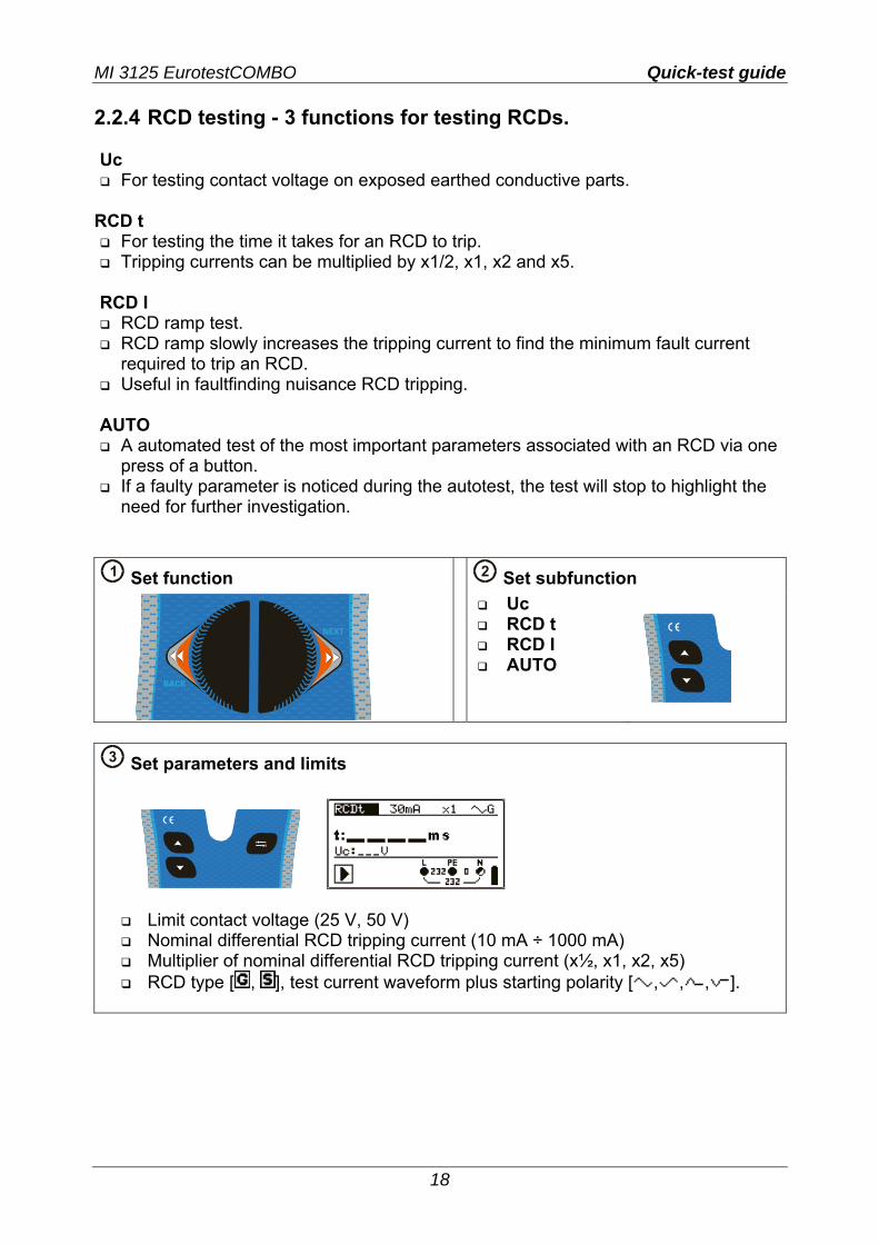
1 Set function 2 Set subfunction
Uc RCD t RCD I AUTO
3 Set parameters and limits
Limit contact voltage (25 V, 50 V) Nominal differential RCD tripping current (10 mA ÷ 1000 mA) Multiplier of nominal differential RCD tripping current (x½, x1, x2, x5) RCD type [ , ], test current waveform plus starting polarity [ , , , ].
MI 3125 EurotestCOMBO Quick-test guide
19
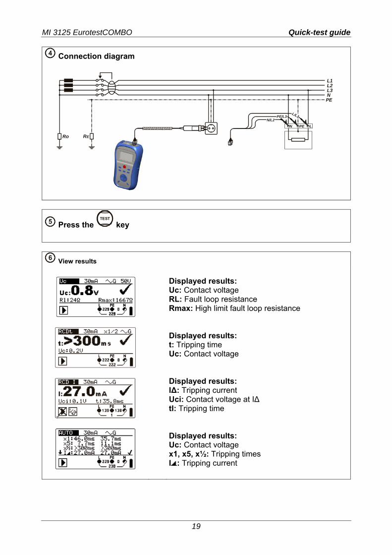
4 Connection diagram
L1L2L3NPE
RERo
LPEN
L/L1N/L2
PE/L3
5 Press the TEST
key
6 View results
Displayed results: Uc: Contact voltage RL: Fault loop resistance Rmax: High limit fault loop resistance Displayed results: t: Tripping time Uc: Contact voltage Displayed results: IΔ: Tripping current Uci: Contact voltage at IΔ tI: Tripping time Displayed results: Uc: Contact voltage x1, x5, x½: Tripping times I : Tripping current
MI 3125 EurotestCOMBO Quick-test guide
20
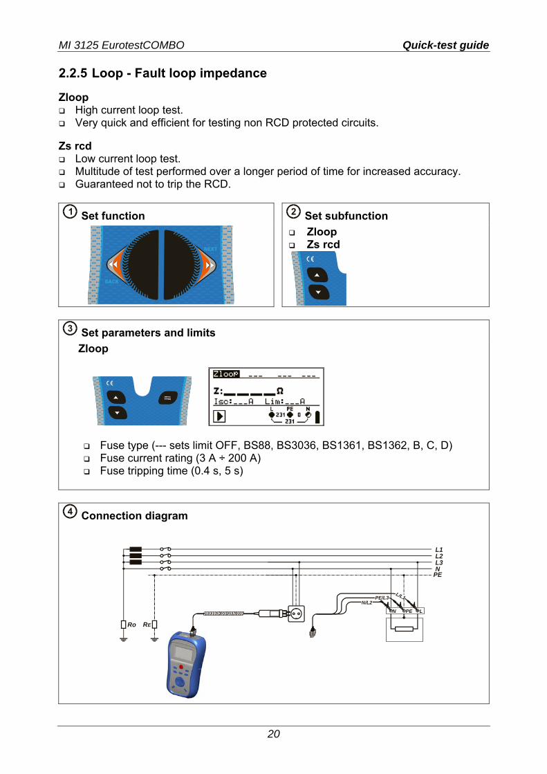
2.2.5 Loop - Fault loop impedance Zloop
High current loop test. Very quick and efficient for testing non RCD protected circuits.
Zs rcd
Low current loop test. Multitude of test performed over a longer period of time for increased accuracy. Guaranteed not to trip the RCD.
1 Set function
2 Set subfunction
Zloop Zs rcd
3 Set parameters and limits
Zloop
Fuse type (--- sets limit OFF, BS88, BS3036, BS1361, BS1362, B, C, D) Fuse current rating (3 A ÷ 200 A) Fuse tripping time (0.4 s, 5 s)
4 Connection diagram
L1L2L3N
PE
RERo
LPEN
L/L1N/L2
PE/L3
MI 3125 EurotestCOMBO Quick-test guide
21
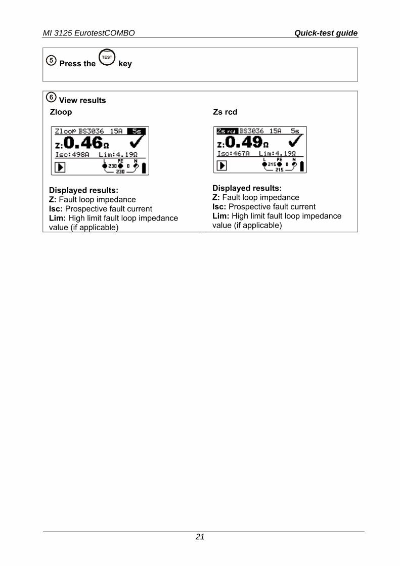
5 Press the TEST
key
6 View results
Zloop
Displayed results: Z: Fault loop impedance Isc: Prospective fault current Lim: High limit fault loop impedance value (if applicable)
Zs rcd
Displayed results: Z: Fault loop impedance Isc: Prospective fault current Lim: High limit fault loop impedance value (if applicable)
MI 3125 EurotestCOMBO Quick-test guide
22
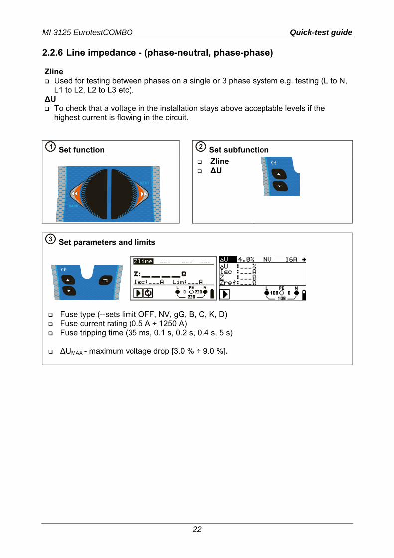
2.2.6 Line impedance - (phase-neutral, phase-phase) Zline
Used for testing between phases on a single or 3 phase system e.g. testing (L to N, L1 to L2, L2 to L3 etc).
ΔU To check that a voltage in the installation stays above acceptable levels if the
highest current is flowing in the circuit.
1 Set function
2 Set subfunction Zline
ΔU
3 Set parameters and limits
Fuse type (--sets limit OFF, NV, gG, B, C, K, D) Fuse current rating (0.5 A ÷ 1250 A) Fuse tripping time (35 ms, 0.1 s, 0.2 s, 0.4 s, 5 s)
ΔUMAX - maximum voltage drop [3.0 % ÷ 9.0 %].
MI 3125 EurotestCOMBO Quick-test guide
23
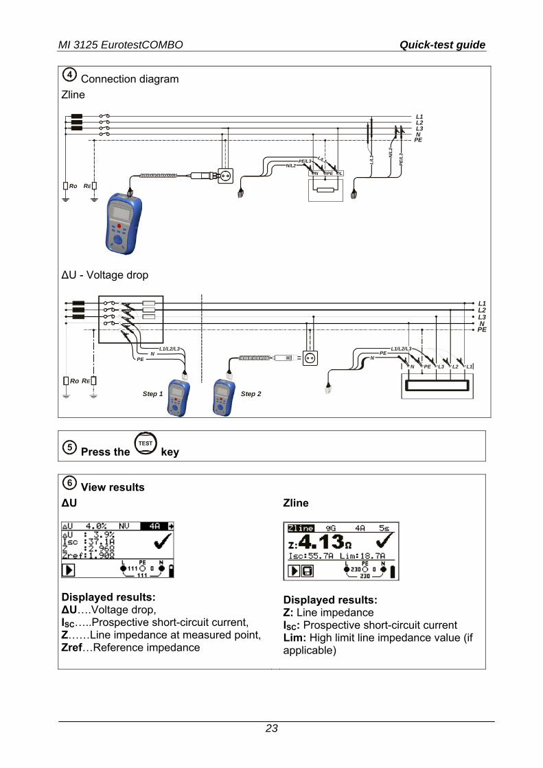
4 Connection diagram
Zline
L1L2L3N
PE
RERo
LPEN
L/L1N/L2
PE/L3
N/L
2
L/L1
PE/L
3
ΔU - Voltage drop
L3N
PE
RERo
PEN
L1/L2/L3
Step 1 Step 2
L2L1
L3PEN
NPE
L2 L1
L1/L2/L3
5 Press the TEST
key
6 View results
ΔU
Displayed results: ΔU….Voltage drop, ISC…..Prospective short-circuit current, Z……Line impedance at measured point, Zref…Reference impedance
Zline
Displayed results: Z: Line impedance ISC: Prospective short-circuit current Lim: High limit line impedance value (if applicable)

MI 3125 EurotestCOMBO Quick-test guide
24