eblienabling power effi iefficient did esigns - ansys import • operate on ... dr. m. pant, lead...
TRANSCRIPT
E bli P Effi i D iEnabling Power Efficient DesignsApache’s Power Noise Simulation T h l iTechnologies
Aveek SarkarVP of Support
© 2011 ANSYS, Inc. August 25, 20111
Apache Design Inc, A wholly‐owned subsidiary of ANSYS

Trends in Today’s Electronic Designs
LowLow--powerpower HighHigh--speedspeedIntegrationIntegration
• Multi-VDD• Power
Gates
• Multi-VDD• Power
Gates• GHz+• Multi-Core • GHz+• Multi-Core
• IP, memories
• Mixed i l
• IP, memories
• Mixed i l• Clock
Gating• Clock
Gating• DDR3+• DDR3+signal
• Stacked diesignal
• Stacked die
Handset Mobile Processors
~ 2.5GHz+
Data Center Processors
~ 3.5GHz+
© 2011 ANSYS, Inc. August 25, 20112
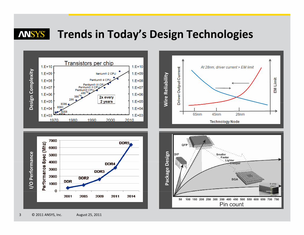
Trends in Today’s Design Technologies
ytytyty
Wire Re
liability
sign
Com
plexit
sign
Com
plexit
sign
Com
plexit
W
Des
Des
Des
esign
esign
esign
ance
ance
ance
Package De
Package De
Package De
I/O Perform
I/O Perform
I/O Perform
© 2011 ANSYS, Inc. August 25, 20113

Impact of Increasing Design Integration
Switching
PowerPowerStandby
Noise CouplingNoise Coupling
Performance
ESD
p gp gFunctionality
ReliabilityReliability
ESD
EM
© 2011 ANSYS, Inc. August 25, 20114

Apache’s Focus Areas
Power BudgetingPower Budgeting
Low power need is ubiquitous
Energycosts
Batterylife
InterferenceEnergyefficiency
PowerPower--Induced Induced NoiseNoise
Unintentional electrical interference
Power Delivery IntegrityPower Delivery Integrity
Right place, right time, right amount
© 2011 ANSYS, Inc. August 25, 20115

Apache’s Power Flow
Architectural Level SimulationPowerArtist™
• Early power simulation• Power reduction
IC Physical Design Simulation • Design prototypingRedHawk/Totem™ • Sign‐off validation
System Integration SimulationSentinel™ / SiWave™
• SI, PI, EMI, Thermal• Co‐verification and optimization
© 2011 ANSYS, Inc. August 25, 20116

Simulation Driven Power Budgeting
Get maximum savings for the Get maximum savings for the t bl i tt bl i t
Power savings saturate here!
acceptable area impactacceptable area impact
Maximum Maximum acceptable acceptable area area impact?impact?
Power vs. Area trade-off: Min area impact for ~Max savings
Power Savings
377k instances, 350MHz, 90nm
Power SavingsArea Impact
© 2011 ANSYS, Inc. August 25, 20117
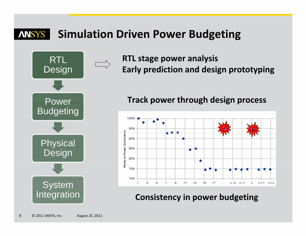
Simulation Driven Power Budgeting
RTL stage power analysisEarly prediction and design prototyping
RTL Design y p g p yp gg
Power Track power through design processPower Budgeting
p g g p
Physical Design
System I t ti
© 2011 ANSYS, Inc. August 25, 20118
Integration Consistency in power budgeting

Simulation Driven “Power Bug” Isolation
• Multi‐core (4) designr r r ( ) g• Not all four cores operational at
any one time
Logic
RegisterLogic
RegisterLogic
Register
• Assuming only first core is operational, rest are shut‐off
• Typically clock is shut off for
Logic
RegisterLogic
RegisterLogic
Register
non‐active blocksLogic
RegisterLogic
RegisterLogic
Register
• But data continues to come inL i ti t b
Logic
RegisterLogic
RegisterLogic
Register
• Logic continues to burn power
PowerArtist Identified this “Power Bug”Reducing Power by 22% PowerArtist Identified this “Power Bug”Reducing Power by 22%
© 2011 ANSYS, Inc. August 25, 20119
g yg y

Power Noise IntegrityI t f L P T h i
Multiple Voltage Islands
Impact of Low Power Techniques
Multiple Voltage Islands
• 100+ VDD/VSS domains
• No re‐distribution or plane sharing
Power Gating
• Disrupts continuity of PDN
• ‘Over‐design’ = large cost
On‐chip Voltage Regulators (LDO)
• Non‐ideal voltage supply
© 2011 ANSYS, Inc. August 25, 201110
• Stability and noise immunity

Power Noise IntegrityI t f T h l Mi tiImpact of Technology Migration
Source: Mezhiba et al. Scaling Trends of On‐Chip Power Distribution NoiseITRS, Trends in technology scaling
Higher impact of inductive noise Ldi/dtHigher drive strength devices di/dt Higher impact of inductive noise Ldi/dtHigher drive strength devices di/dt
But … noise margin continues to reduce
• Reduced FMAX
• Functionality failures
• Over‐design requirements
© 2011 ANSYS, Inc. August 25, 201111
Over design requirements

RedHawk Power Noise Analysis Flow
• CAD design flow independent• Operate on industry standard formats:Design Import
PG Extraction• Only solution for on‐die ‘L’ extraction and simulation• Silicon validated down to 28nm and beyondy
• Pico‐second resolution, native multi‐domain• Best‐in‐class performanceSimulation p
Root Cause • Enable automatic and user guided debug
Identification • Interactive ‘what‐if’ and incremental simulation
• Single step model creation out of RedHawk
© 2011 ANSYS, Inc. August 25, 201112
Single step model creation out of RedHawk• Multi‐domain, distributed and coupled
Chip Power Model

RedHawk Power Noise Analysis Coverage
Core Noise Core ↔ I/O Core ↔ Analog
PLLnoise so rce
Scenario 3Scenario 2
guard ring
source victim
Scenario 1
• Multi‐core switching• Power gate turn‐on/off
• I/O , core SSO• Irregular bump, package
• High‐speed digital• Insufficient isolation
© 2011 ANSYS, Inc. August 25, 201113

Addressing Customer’s Market Needs
“Accurate pre‐silicon power delivery simulations are an
essential tool to predict the
Exploding design and
k
impacts of tester and system
power delivery performance on
silicon frequency andmask costs
f q y
reliability.”
Dr. M. Pant, Lead technologist and power delivery architect, Xeon and Itanium server products
GSA Global “Electronic System Design Considerations to Meet Emerging Market Needs”
© 2011 ANSYS, Inc. August 25, 201114

Apache’s Power Tools
Architecture IP SoC Package PCB
Power Budgeting
Power Delivery Integrity
© 2011 ANSYS, Inc. August 25, 201115
Power‐Induced Noise