ebz7500/ 8500 workshop manual
TRANSCRIPT

Workshop Manual [2017]
EBZ7500/ 8500

This workshop manual describes the main maintenance items and procedures for the
Husqvarna Zenoah engine blower EBZ7500/ 8500. This manual is classified into three
categories.
Special tools for maintenance
Notice of teardown and reassembly
Inspection and adjustment of the carburetor
As reference information, the technical data, the maintenance standard and the
troubleshooting are listed, too.
After each item is thoroughly understood, apply the understanding to the actual maintenance
tasks. Frequently asked questions are also included in this manual. However, many cases
need rich maintenance experience and informed judgment. Please refer to this manual for
maintenance support.
“WARNING”
1. The contents of this manual are based on specifications as of 2017. The contents may be modified due to performance improvement or some other reason without notice.
2. Use Zenoah brand-name parts when replacing a part during maintenance, etc. The manufacturer does not bear any responsibility if trouble occurs owing to use of parts other than those endorsed by our brand.
3. Read this manual thoroughly before beginning the maintenance work, understand it, apply the content to the actual maintenance tasks and guide the customer if directions are needed.

Contents
-1-
1. Features of Engine Blower
1-1 Fan and Volute Case ······························· 2
1-2 Pipes ··················································· 3
1-3 Air Cleaner ············································ 4
1-4 Measures Against Static Electricity ············· 4
2. Strato-charged Engine
2-1 Outline ················································· 5
2-2 Operating Principle ································· 6
3. Constructions - Exploded View ············ 7
4. Technical Data
4-1 Blower ················································· 8
4-2 External Dimensions ······························· 9
4-3 Pipe and Nozzles ·································· 10
5. Special Tools
5-1 Description ··········································· 11
5-2 How to Use ·········································· 12
6. Notice of Teardown
6-1 Guard Net Removal ······························· 21
6-2 Lower Damper Removal ························· 21
6-3 Crankcase and Crankshaft Disassembly ····· 22
6-4 Oil Seal and Rearing Removal·················· 23
7. Notice of Reassembly
7-1 Engine Short Block Assembly ··················· 24
7-2 Handling of the bolt with a thread lock ········ 28
7-3 Muffler Installation ································· 29
7-4 Rotor Installation ··································· 29
7-5 Ignition Coil Installation ··························· 30
7-6 Coupling Installation ······························· 31
7-7 Carburetor Installation ···························· 31
7-8 Fan Installation ····································· 32
7-9 Recoil Starter Installation ························ 32
7-10 Engine Cover Installation ······················· 33
7-11 Intake Hose Installation ························· 33
7-12 Frame Installation ································ 34
7-13 Fuel Pipes Installation ··························· 35
7-14 Switch Cords and Cable Installation ········· 36
7-15 Elbow Installation ································· 36
7-16 Recoil Starter Assembly ························ 37
7-17 LHD-Throttle Lever Set Assembly ············ 40
7-17 RHD-Throttle Lever Set Assembly ··········· 42
8. Carburetor
8-1 Technical Data······································ 44
8-2 Description ·········································· 45
8-3 Inspection ··········································· 46
8-4 Adjustment ·········································· 50
9. Maintenance Standards/ Tightening Torques
9-1 Standards and Service Ability Limit ··········· 53
9-2 Tightening Torque ································· 54
10. Troubleshooting
10-1 Engine does not star ···························· 55
10-2 Engine stop during operation ················· 56
10-3 Engine cannot be stopped ····················· 56
10-4 Lack of output power or unstable
revolution ·········································· 57
10-5 The amount of the wind is weak ·············· 57
10-6 Others ·············································· 58

-2-
1 . Features of Engine Blower
1-1 Fan and Volute Case
Air is sucked from the whole circumference of the full cover type guard net and from the side structure of the
newly designed blow molding frame to send a lot of air to the fan. The fan uses a half-closed fan, optimizing
the air flow with the new flat volute case, realizing the very best of the air volume and wind velocity.
Intake from the side of the frame.
Guard Net
New type Flat Volute Case
Half-closed Fan
The notches are formed in the shroud (wing covering) and
height of fins is increased while maintaining rigidity in
order to increase wind volume and decrease the weight.
Blow molded
new frame

-3-
1 . Features of Engine Blower
1-2 Pipes
BZ7500
The tip of the pipe end is cut obliquely so that the
wind flows slightly downward. By letting the wind flow
downward, holding of the pipe feels lightly. It
promotes easy operation.
EBZ8500
By increasing the diameter of the aperture of the
pipe end, the wind loss at the pipe outlet is reduced.
The maximum air volume in this class is acquired.
EBZ7500/ 8500
The new spiral type flexible hose has no sharp on its
surface contrary to the conventional flexible hose. It
is hard to split and has excellent durability.
In addition, wind resistance is reduced compared
with conventional uneven path.
Wind direction 3 to 5 degrees downward
Indication of the orientation of installation
NOTE:
If the pipe end is set upside down, it gives you a powerful feeling to blow the object far, but you will need power to hold the grip.
Cut it obliquely.
Outlet inner diameter φ84mm
φ76mm Flare
Conventional flexible hose
New type spiral flexible hose

-4-
1 . Features of Engine Blower
1-3 Air Cleaner
EBZ7500/ 8500
It is equipped with a large capacity cleaner with
double structure of pre-filter and paper filter. The
high cleaning efficiency realizes longer time to
clogging even at sites where there are many dust.
EBZ8500
The fresh air intake system is used. Because the
clean air in the volute case is taken in directly through
the dedicated passage, it is powerful and the
maintenance interval can be lengthened.
1-4 Measures Against Static Electricity
A conductive throttle lever discharges static
electricity through the hands of the operator.
Throttle Lever
Air Cleaner Cover
Paper Filter
Pre-filter
Air Cleaner Body
Fresh Air Intake Passage
Air Cleaner Case
Volute Case

-5-
2. Strato-charged Engine
2-1 Outline
■ Efforts to the exhaust gas regulations
Husqvarna Zenoah has developed its own "Strato-charged
Engine" as a two-stroke engine compliant with exhaust gas
regulations since 1999, and it has been in compliance with the
regulations of each country starting from the US.
The Strato-charged engine realizes clean exhaust while taking
advantage of two-stroke engine.
■ Structure
Normally, approximately 30% of unburned gas is discharged in a two-stroke engine, because air-fuel
mixture pushes out the combustion gas. However, Husqvarna Zenoah's Strato-charged engine adopts
"air-guided stratified scavenging system" which introduces leading air to the scavenging port separately
from the air-fuel mixture. The leading air pushes out the combustion gas in order to prevent blowing out
of unburned gas resulting in reduction of the concentration of hydrocarbons in the exhaust gas.
■ Features
Because it does not use any special equipment, it is lightweight with a simple structure.
Excellent cooling performance promotes stable output performance even in continuous operation in
summer.
It realizes low fuel consumption of 40% or less. (In comparison with our previous model)
混合気
Lead Air Venturi
Air-fuel Mixture Venturi
Carburetor
Scavenging Port
Piston Groove
Lead Air Intake Port
Air-fuel Mixture
Intake Port

-6-
2. Strato-charged Engine
2-2 Operating Principle
1. As the piston proceeds through the upstroke
of the intake cycle, the crankcase vacuum
sucks the lead air in through the scavenging
port via the groove on the piston skirt.
2. As the piston begins its downstroke after top
dead center, a scavenging port starts to open
and lead air in the scavenging port moves into
the cylinder earlier than the air-fuel mixture.
3. As the piston begins its upstroke after bottom
dead center, burnt gas in the cylinder is pushed
out through the exhaust port by lead air.
Therefore, almost no air-fuel mixture is emitted.
Piston
Exhaust Port
Burnt Gas
Air-fuel Mixture
Lead Air
Air-fuel Mixture
Lead Air

-7-
3. Constructions - Exploded View
7-9 Recoil Starter Installation (see page 32)
7-16 Recoil Starter Assembly (see page 37)
7-10 Engine Cover Installation (see page 33)
7-5 Ignition Coil Installation (see page 30)
7-4 Rotor Installation (see page 29)
7-14 Switch Cords and Cable Installation
(see page 36)
7-3 Muffler Installation (see page 29)
7-13 Fuel Pipe Installation
(see page 35)
6-1 Guard Net Removal (see page 21)
7-12 Frame Installation (see page 34)
7-17 LHD-Throttle Lever Set
Assembly (see page 40)
7-8 Fan Installation (see page 32)
7-15 Elbow Installation (see page 36)
7-11 Intake Hose Installation
(see page 33)
6-2 Lower Damper Removal
(see page 21)
7-6 Coupling Installation
(see page 31)
7-7 Carburetor Installation (see page 31)
8 Carburetor (see page 44)
6-3 Crankcase and Crankshaft Disassembly (see page 22)
6-5 Oil seal and Bearing Removal (see page 23)
7-1 Engine Short Block Assembly (see page 24)
7-17 RHD-Throttle Lever Set
Assembly (see page 42)

-8-
4. Technical Data
4-1 Blowers
Item Unit Specifications
Remarks Category - Back-pack Engine Blower
Engine Types - GZ66N5 GZ76N3
Blower Models - EBZ7500 EBZ8500
Cycle - Two-stroke ←
Number of Cylinders - 1 ←
Valve Type - Piston valve ←
Cylinder Bore mm 47.5 51
Stroke mm 37 ←
Displacement cm3 65.6 75.6
Fuel - Lubricating blended gasoline ←
Engine lubrication - Fuel-oil mixture ←
Engine lubrication Oil - Two-stroke engine oil ←
Mixing Ratio - Zenoah FC 40:1/ Zenoah FD 50:1 ←
Carburetor Type - Diaphragm type rotary throttle valve ←
Models - Walbro WYA-236A Walbro WYA-237A
Starting Method - Recoil starter ←
Ignition System - Digital controlled (CDI) with automatic timing advance
← Digital control misfire for excessive speed maximum speed: 8,500 rpm
Ignition Timing BTDC °/rpm 30.5/ 7,000 ←
Spark Plug Type - NGK CMR7H ← Noise-proof
Gap mm 0.6 to 0.7 ←
Stopping Method
Type - Primary coil short-circuiting ←
Switch - Push type ←
Cooling System - Forced air cooling ←
Air Cleaner Element Type - Primary: Dry puff
Secondary: Dry paper ← Two stage filters
Output Axle Rotation Direction
- Counterclockwise ← View from output axle
Dimensions
Length mm 354※ 357※ ※Throttle arm vertical state
Width mm 536※ 535※ ※Throttle arm vertical state
Height mm 499 540
Body dry weight with standard pipes
kg 10.6 (9.6) 11.2 (10.2) ( ): Elbow included,
without blower pipes
Fuel Tank Capacity L 2.1 2.3
Idling Speed rpm 2,000 ← Idling speed stability:±200
Operating Speed rpm 7,250 ← Wide open throttle stability:±100
Pipe Nozzle Diameter mm 72 84
Average air volume at aimed blowing point
m3/ m 21.8 25.7 ANSI
Maximum air speed at aimed blowing point
m/s 105.6 92.2 ANSI
Maximum Output kW/rpm (PS/rpm)
2.8/ 7,200 (3.8/ 7,200)
3.3/ 7,250 (4.49/ 7,250)
Fuel Consumption L/h 1.85 2.07 Under actual blower state
Ambient noise at 15 m from the blower
dB(A) 77 ← ANSI B.175.2-2000
Noise at operator dB(A) 103.4 103.2 Reference
Sound Power Level dB(A) 110 ← ISO11094 (EBZ7500/ 8500)

-9-
4. Technical Data
4-2 External Dimensions
Unit:mm
Models A B BB C D
EBZ7500 354 536 479 499 1198
EBZ8500 357 535 497 540 1198
Illustration shown is EBZ7500.
☆: Reference.

-10-
4. Technical Data
4-3 Pipes
Unit:mm
Part No. 576 56 47-01 576 56 51-01 576 56 48-01
Name Flexible Hose Grip Assembly Swivel Joint
Appearance
Applicable Inner diam.
d1
Inner diam.
d2
Length
L1 Inner diam. d3
Outer diam.
D4
Outer diam.
D5
Length
L2
EBZ7500 φ99.5 φ99.5 349 φ97.4 φ99 φ103 340
EBZ8500
Part No. 576 56 49-01 576 56 50-01 576 57 64-01
Name Straight Pipe Pipe End Pipe End
Appearance
Air velocity type
Air volume type
Applicable Inner diam.
d6
Outer diam.
D7
Length
L3
Inner diam.
d8
Inner diam.
d9
Length
L4
Inner diam.
d10
Inner diam.
d11
Length
L5
EBZ7500 φ103 φ103 380
φ103 φ72 350 ― ― ―
EBZ8500 ― ― ― φ103 φ84 350

-11-
5. Special Tools
5-1 Description
Tool Name Tool Number Appearance Usage
Torx Wrench 2850-96410
Size: T20/ T25/ T27 Bolt and screw loosen/ tighten
Socket Key H502502301
Size: M10
Damper nut loosen/ tighten
Puller Assy. 577 40 97-01
Rotor and coupling removal (see pages 13
and 14)
Gauge
0.3mm
516 88 03-01
(2750-96240)
Ignition coil setting (Air gap) (see page 15)
Rod Assy. 516 18 29-01
(1101-96220)
Piston pin removal or installation
(see page 16)
Bearing Guide 577 40 98-01
Main bearing installation (see page 16)
Crankshaft
Installing Tool
① 582 04 35-01
② 582 04 36-01
③ 01582-01613
Press the crankshaft to the PTO side
crankcase.
Guide also used for press of the oil seals.
(see pages 16, 17 and 18)
①
② ① Guide ② Bolt ③ Nut
Crankcase
Support 577 41 01-01
When pressing the bearing, oil seal and crankshaft, support the crankcase (see pages 16 and 17).
① ②
③

-12-
5. Special Tools
5-1 Description
Tool Name Tool Number Appearance Usage
Pressure
Vacuum Gauge H531030623
Engine seal check (see page 19)
Pressure Tester
Attachment H503844001
Set in the hole of the spark plug, and
connect the pressure gauge
(see page 19).
Outlet Cover
Plate H502541102
Closure of exhaust port and inlet port
(see page 19)
Compression
Gauge (φ14mm)
Adapter Size:
(φ10mm)
H531031686
583 84 98-01
Compression pressure check (see page 18)
Piston Fitting Kit H502507001
Piston installation (see pages 17 and 20)
Fuel Filter Hook H502508301
Suspending the fuel filter
Fuel Filter
φ10 Adapter φ10
Stopper
Do not use.
φ10

-13-
5. Special Tools
5-2 How to use
Item Procedures
-1)
Rotor Removal
1. Remove the recoil starter, the engine
cover, the intake hose and the spark plug.
2. Turn the rotor to the clockwise (CW) 90
degrees from the TDC.
NOTE:
The piston TDC is the position where
the "S" mark of the rotor is aligned with
the center of the cylinder.
3. Insert the recoil rope into the cylinder from
the plug hole to stop the movement of the
piston.
4. Remove the mounting nut of the rotor.
NOTE:
Turn the rotor counterclockwise (CCW)
slowly, contact the piston head to the
recoil rope lightly and loosen the nut.
5. Set the puller (special tool) to the rotor.
NOTE:
When attaching the puller bolts, screw
in more than half of the threaded
portion to the rotor.
6. Tighten the center bolt of the puller and
remove the rotor from the crankshaft.
Recoil Rope
“S” Mark
Rotor
Puller Bolts
17 mm Hex
Puller
Rotor
Mounting Nut
(14 mm Hex)

-14-
5. Special Tools
5-2 How to use
Item Procedures
-2)
Coupling Removal
1. Remove the recoil starter, the engine
cover, the intake hose, the fan, the volute
case and the spark plug.
2. Turn the rotor to the counterclockwise
(CCW) 90 degrees from the TDC. Insert
the recoil rope into the cylinder from the
plug hole to stop the movement of the
piston.
3. Remove themounting nut of the coupling.
NOTE:
Turn the coupling counterclockwise
(CCW) slowly, contact the piston head
to the recoil rope lightly and loosen the
nut.
4. Set the puller (special tool) to the coupling.
NOTE:
When attaching the puller bolts, screw
in more than half of the threaded
portion to the coupling.
5. Tighten the center bolt of the puller and
remove the coupling from the crankshaft.
Recoil Rope
Rotor
Coupling
“S” Mark
Mounting Nut
(14 mm Hex)
17 mm Hex
Coupling
Puller Bolts Puller

-15-
5. Special Tools
5-2 How to use
Item Procedures
-3)
Ignition Coil Installation (Adjusting air gap)
1. Apply thread lock to the mounting bolts.
Set the spacers, the ignition coil and the
terminal, and temporarily tighten the
mounting bolts。
Thread Lock: Three Bond #1342/1342H
or equivalent
2. Insert the gauge (special tool) between the
rotor magnet metal and ignition coil.
Tighten the mounting bolts while pushing
the ignition coil against the rotor.
Torque: 2.45~3.92N・m (25~40kgf・cm)
NOTE:
When contacting the iron core of the
ignition coil and part of the rotor
magnet metal, the engine may stop
suddenly. Secure the air gap (03.mm)
using the gauge.
[Resistance]
The resistance values shown above are the reference values for resistance tester
measurement. The resistance value within the normal range shows no internal leakage or
any other defect.
Ignition Checker (Tool No. 3699-90247)
We supply the measurement
equipment (Ignition Checker) that can
measure spark energy while the
engine is running. When measuring
the spark energy, discharge gaps are
different depending on the connected
place of the alligator clip.
Refer to the ignition checker
manufacturer’s instruction details.
Rotor
Gauge (0.3mm)
Ignition Coil Spacer
0.3mm
0.3mm
プラグキャップ
Mounting Bolts M4x 22L (T27)
Spacer
High-tension Cord
Iron Core
Primary
Lead
Resistance (Reference)
Air Gap Primary side
(Iron Core ↔ Primary Terminal) Secondary Side
(Iron Core ↔ Secondary Side)
90kΩ±20% 2kΩ±10% 0.3mm
Discharge Window
If connected to the engine.
Discharge gaps: 6mm
If connected to the spark plug.
Discharge gaps: 4mm
Discharge Gap Adjustment Knob Plug Cap

-16-
5. Special Tools
5-2 How to use
Item Procedures
-4)
Piston Pin Removal/ Installation
1. Remove the cylinder from the engine short
block.
2. Remove the snap ring on the fan side of
the piston and remove the piston pin from
the piston.
NOTE:
The piston pin can be removed without
using a tool usually. If it is difficult to
remove, use the rod assy. (special tool)
to push out from the piston.
-5)
Press of Bearing Illustration shows the MAG side. PTO side similar.
-S: Starter side
1. Set the support (special tool) outside of
the crankcase-S as shown.
2. Tap the bearing with a plastic hammer
lightly and fit it into the crankcase
horizontally.
3. Insert the bearing guide (special tool) to
the bearing and press the bearing into the
crankcase using a press.
-6)
Press of Starter side Oil Seal
1. Set the support (special tool) inside of the
crankcase-S as shown.
2. Press the guide (special tool) against the
oil seal and press the oil seal into the
crankcase-S with a press.
Guide
(① of Crankshaft
installing tool)
Oil Seal
Bearing
Support
Rod Assy. Piston
Piston Pin
Snap Ring
Bearing Guide
Crankcase-S
Crankcase-S
Support

-17-
5. Special Tools
5-2 How to use
Item Procedures
-7)
Press of Crankshaft -F: Fan side -S: Starter side
In the case of the crankshaft reuse, the fit
between the crankshaft and the crankcase-F
side of the bearing may be slightly tight.
1. Insert the crankshaft until halfway into the
crankcase-F.
2. Insert the guide of the crankshaft installing
tool (special tool) into the crankshaft, and
contact the tip of it to the inner race of the
bearing. Screw the bolt to the crankshaft
and fix it with the nut as shown.
3. Fix the connecting rod with the plate of
piston fitting kit (special tool) so that the
crankshaft does not turn.
4. Fix the bolt and insert the crankshaft into
the bearing while screwing the nut.
NOTE:
After press, rotate the crankshaft to
check the operation of the bearing.
If the movement of the bearing is
heavy, tap the bolt head with a plastic
hammer to release the pressure on the
bearing.
5. Set the support (special tool) outside of
the crankcase-S as shown.
6. Set the crankcase gasket and temporarily
install the mounting bolts.
7. Set the guide of the crankshaft installing
tool (special tool) on the crankcase-F and
press the crankshaft into the crankcase-S
with a press.
NOTE:
When inserting the crankshaft, do not
damage the lip of the oil seal on the
crankcase-S side at the edge of the
shaft.
Crankshaft Plate
Guide
Nut
Tighten. Bolt Fix. Crankcase-F
Guide Bolt Crankshaft
Bearing
Nut
Crankcase-F
Crankcase Gasket
Support
Crankcase-S
Crankcase-F
Press Guide
(① of Crankshaft
installing tool)

-18-
5. Special Tools
5-2 How to use
Item Procedures
-8)
Press of Fan side Oil Seal
1. Insert the oil seal to the crankcase-F until
it stops with your fingers.
NOTE:
When inserting the oil seal, do not
damage the lip of it at the edge of the
crankshaft.
Insert the oil seal horizontally so as
not to be tilt.
Because there is a groove preventing
coming off on the outside of the oil
seal, its insertion is not easy.
2. Place the guide (special tool) against the
oil seal and tap it with a hammer to press
the oil seal into the crankcase-F.
NOTE:
After press, rotate the crankshaft to
check the operation of the bearing.
-9)
Compression Pressure Check
1. Warm-up the engine for at least 5 minutes.
NOTE:
After warm-up, the engine and the
muffler will become hot. Be careful
not to burn yourself.
2. Remove the attachment of the
compression gauge (special tool) and
attach the adapter (φ10mm).
3. Remove the spark plug and set the
compression gauge (special tool) to the
cylinder.
4. Pull the recoil knob quickly and strongly
about 5 times.
More than 8.4 kg/cm2 (872kPa) is fine.
“This value is only an estimate.”
NOTE:
Engine parts is not thermal expansion
in the warm-up the shortage, or
immediately after replacement with
the new part, cannot be to correctly
measure the compression pressure.
Compression Gauge (φ14mm)
Adapter (φ10mm)
Oil Seal Push with a finger.
Crankcase-F
Attachment Do not use.
Guide
(① of Crankshaft
installing tool)

-19-
5. Special Tools
5-2 How to use
Item Procedures
-10)
Engine Seal Check
1. Remove the muffler and the gasket.
2. Temporarily install the muffler and insert
the outlet cover plate (special tool)
diagonally between the muffler and the
exhaust port of the cylinder. Tighten the
bolts, then close the exhaust port.
3. Remove the spark plug, set the pressure
tester attachment (special tool) to the
cylinder.
4. Remove the intake cup, the carburetor
and the gasket.
5. Temporarily install the carburetor and the
intake cup, and insert the outlet cover
plate (special tool) between the carburetor
and the insulator. Tighten the bolts, then
close the intake port.
NOTE:
Cut the outlet cover plate so that the
intake port is closed surely.
Outlet Cover Plate
Carburetor
Gasket
Intake Cup
Muffler
Pressure Tester Attachment
Gasket
Outlet Cover Plate
Muffler
Outlet Cover
Plate
Outlet Cover Plate
Cut the shaded area.
Cut the shaded area.

-20-
5. Special Tools
5-2 How to use
Item Procedures
-10)
Engine Seal Check
6. Connect the pressure vacuum gauge
(special tool) to the pressure tester
attachment of the cylinder.
7. Adjust the "Pressure Mode" press to
80 kPa.
After 30 seconds, if the seal stays at
60 kPa, the sealing should be fine
NOTE:
After installing the muffler, operate the
engine by wide open throttle more than
one minute, and retightening the
mounting bolts.
-11)
Piston Installation
When inserting the piston into the cylinder, fix
the piston with the plate of the piston fitting kit
(special tool) and hold the piston rings with
the ring tool.
Ring Tool Piston
Cylinder
Piston Rings
Plate
切
替
え
ノ
ブ
Pressure Vacuum Gauge
Select Knob
Select Knob
Pressure Mode
Vacuum Mode

-21-
6. Notice of Teardown
6-1 Guard Net Removal
The guard net is mounted by four clips. The removal
procedure is shown below.
1. Loosen the resin screw of the clip and remove it
completely.
NOTE:
When loosening the resin screw, securely fit
the Phillips screwdriver into the (+) of the
screw head. If not fitted, the screw head will
be damaged.
2. Insert the flat tip screwdriver between the guard
net and the frame, twist the screwdriver to pull out
the clip, and remove the guard net from the
frame.
NOTE:
Do not damage the guard net and frame with
the screwdriver.
6-2 Lower Damper Removal
Remove the volute case from the frame.
Remove the cover and pull out the lower damper
from the groove of the volute case.
Clip
Flat Tip Screwdriver
Resin Screw
Guard Net
Volute Case
Screws (3)
Cover Lower Damper
Frame
Mounted positions (4)

-22-
6. Notice of Teardown
6-3 Crankcase and Crankshaft Disassembly
1. Remove the mounting bolts, twist the flat-tip
screwdriver at the two notches of the crankcase,
then separate the crankcase-S and the
crankcase-F. If necessary, gently tap with a
plastic hammer to the crankcase-F.
2. Remove the crankcase-F from the crankcase-S
with the crankshaft.
NOTE:
The crankshaft cannot be removed from the
crankcase-F in this state because the main
bearing of the crankcase-F and the crankshaft
are very tight fitting.
Crankcase-S
Crankshaft Crankcase-F
Crankcase-S
Notch
Notch
Opposite side
Crankcase-F
Crankcase-F
Crankcase-S

-23-
6. Notice of Teardown
6-3 Crankcase and Crankshaft Disassembly
3. Use the press to remove the crankshaft from the
crankcase-F.
NOTE:
Do not remove the crankshaft by tapping with
an iron hammer because it may cause the
rotation of the crankshaft will be off-balance
or the thread may be damaged.
6-4 Oil Seal and Bearing Removal
Check wear of the oil seal, rattling and seizure of
the bearing. If necessary replace them.
If the bearing press-fitting portion of the crankcase
is worn, replace the crankcase at the same time.
NOTE:
Be sure to remove the bearing using a press.
If do not use a press, the crankcase may be
damaged.
Never reuse the bearings and the oil seals.
Press
Guide
(Commercially available tool)
Crankcase
Bearing
Support
Press
Crankshaft
Crankcase-F
Support
Bearing
Oil Seal
Crankcase-F
Crankcase-S
Bearing
Oil Seal

-24-
7. Notice of Reassembly
7-1 Engine Short Block Assembly
1) Lubricating and Degreasing
Apply two-stroke engine oil to the inner surface of the main bearings, needle bearing, between the crank
weight and the connecting rod large end.
Apply two-stroke engine oil to the inner surface of the cylinder and the outer periphery of the piston
excluding the piston head.
Apply heat-resistant grease No.2 to the inner surface and lip of the oil seals.
Degrease the outer surface of the main bearings and the bearing contact surface of the crankcase.
Degrease the taper and thread portion of the crankshaft.
Degrease the outer surfaces of the oil seals.
Crankcase-F
Crankcase-S
Oil Seal
Starter side
Oil Seal
Crankcase
Oil Seal
Two-stroke oil applying location
Degreasing location
Cylinder
Bolts (4) M5x 22L (T27)
Torque: 5.88~8.82N・m (60~90kgf・cm)
Snap Ring Piston
Needle Bearing
Piston Pin Fan side
Bearing
Degreasing
Bearing
Connecting rod
large end
Bolts (4) M5x 30L (T27)
Torque: 5.88~7.84N・m (60~80kgf・cm)
Degreasing
Degreasing

-25-
7. Notice of Reassembly
7-1 Engine Short Block Assembly
2) Main Bearing and Oil Seal
Press the bearing using the bearing guide of
the special tool (see page 16).
Press the oil seal using the guide of the
crankshaft installing tool (special tool) (see
page 16).
NOTE:
After assembling the crankshaft, press the oil
seal of the crankcase-F (See page 18).
NOTE:
Never reuse the bearings and the oil seals.
3) Crankshaft
Confirm the assembly direction of the
crankshaft. Set the crankshaft to the TDC
position, the keyway of the shaft is downward
and the short taper is the crankcase-F side.
Insert the crankshaft into the crankcase-F
using the crankshaft installing tool of special
tool (see page 17).
Check that the crank weight edge and the
clearance of both sides of the crankcase edge
be equal. When a gap is not equal, tap the
crankshaft of the side where a gap is small
with a plastic hammer and do a gap equally.
Bearing Guide
Bearing
Guide
1.5mm
Guide
Crankshaft
Oil Seal
Plate
Crankshaft Installing Tool
Crankshaft
Crankcase-F
Crank Weight
Crankcase-S Crankcase-F
Confirm that a gap is equal.
Crankcase-F side
TDC position
Crankcase-F
Keyway
Short taper
Crank Weight
Oil Seal

-26-
7. Notice of Reassembly
7-1 Engine Short Block Assembly
4) Crankcase Gasket
NOTE:
Be sure to use the new parts of the crankcase
gasket.
Cut off the crankcase gasket ends exceeding
the cylinder mating surface.
When cutting the gasket, cut it outward from
inside, so that the gasket will not fall into the
inside of the crankcase.
5) Piston Ring
Align the end gap of the piston ring exactly with
stopper pin of the piston.
6) Piston, Piston Pin and Snap Ring
Make sure to point the triangle mark on the
piston head to the exhaust (muffler) side.
Install the piston pin with the rod assy. of
special tool (see page 16).
Fit the snap ring in the groove of the piston
firmly and turn the end gap of the snap ring to
the opposite side of the notch.
After the assembly, check that it moves
smoothly in the groove by turning the snap
ring with a thin tool of the tip. If the snap ring is
not securely fitted into the groove, it does not
move smoothly.
NOTE:
If the snap ring does not fit properly into the
groove or the end gap of the snap ring is
incorrectly positioned, and the snap ring
come off during operation, it may damage the
engine.
Never reuse the snap ring, replace it with a
new on.
Stopper Pin
Piston Ring
Snap Ring
Piston Pin
Groove
End Gap
Notch
Stopper Pin
Piston
Crankcase
Triangle Mark
Exhaust side
Crankcase Gasket Cut off.

-27-
7. Notice of Reassembly
7-1 Engine Short Block Assembly
7) Cylinder Gasket
When setting the cylinder gasket, make the
arrow mark to the fan side.
8) Scavenging Port Cover
Do not remove the scavenging port cover as
much as possible. If removed the scavenging
port cover, make sure to apply the liquid gasket
to the mating surface with the cylinder and install
the scavenging port cover.
NOTE:
The liquid gasket should be applied
continuously without any gaps to ensure
high sealing accuracy of the mating face of
the scavenging port cover and the cylinder.
Liquid gasket:
Three Bond #1217F or equivalent
Torque: 2.0~3.5N・m (20~35kgf・cm)
Cylinder Gasket
Arrow Mark
Scavenging Port Cover
Illustration is the fan side;
starter side is similar.

-28-
7. Notice of Reassembly
7-2 Handling of the bolt with a thread lock
As for EBZ7500/ 8500, a thread lock is applied to the ignition coil, the recoil starter, the insulator mounting
bolts, and the upper damper mounting screws. When handling the mounting bolts or screws, pay attention to
the following items.
NOTE:
When Loctite242 is applied exceeding the proper quantity, the crankcase's internal thread may be
broken. If too much Loctite242 is applied and the crankcase is damaged due to this, Husqvarna
Zenoah will not warrant the damaged case.
【Reuse the bolt/ screw】
1. Remove the old thread lock on the bolt or screw
by using the dies.
2. Remove the old thread lock on the thread holes
of the crankcase, cylinder and the upper damper
by using the tap.
3. Degrease the thread portions, and apply a new
thread lock to the mounting bolt or screw.
NOTE: When tightening the bolt with the old thread lock having stuck, damage the thread portions of the engine side.
Thread Lock:
Three Bond #1342
LOCTITE #222, LOCTITE #242 or equivalent
【Replace the bolt/ screw】
When replacing the new mounting bolts or screw,
remove the old thread lock on the thread holes of
the crankcase, cylinder and the upper damper by
using the tap.
Ignition Coil
Mounting Bolt (2)
M4×0.7 L22
Low intensity:
Loctite #222 or only
one drop of Loctite
#242
Recoil Starter
Mounting Bolt (4)
M5×0.8 L16
Insulator
Mounting Bolt (4)
M5×0.8 L27
Middle intensity:
Loctite #242
Upper Damper
Mounting Screw (2)
M5×0.8 L16
Dies
Thread
Tap
About 10mm
Apply a thread lock to the
coil mounting bolt in the
range of about 3mm from
the tip of the thread.
About 3mm
Middle intensity:
Loctite #242
Middle intensity:
Loctite #242
Thread Hole
Tap
Thread Hole

-29-
7. Notice of Reassembly
7-3 Muffler Installation
Check the muffler for deformation and cracks. If
necessary, replace it with a new one.
Remove the carbon deposits that have
accumulated in the muffler with a screwdriver.
NOTE:
Do not burn the carbon deposits in the muffler
by overheating with the gas torch. If
overheated, it may cause deformation of the
muffler, melting of the inner glass wool, etc.
Remove the carbon deposits on the engine side
exhaust port with the wood stick.
NOTE:
Block the exhaust port with the piston so that
carbon deposits does not fall in the cylinder
Evenly tighten the muffler mounting bolts.
Torque: 7.87~11.76N・m (80~120kgf・cm)
Remove the diffuser and remove the carbon
deposits that have accumulated on the spark
arrester with a wire brush. If necessary, replace it
with a new one.
Torque: 2.0~3.0N・m (20~30kgf・cm)
7-4 Rotor Installation
1. Parallel the flat surface of the key to the center
line of the crankshaft, and set it in the keyway of
the crankshaft. Align the keyway of the rotor with
the key to crankshaft surely and insert it.
NOTE:
Make sure that there is no adhesion of oil or
dust on the tapered surface and the threaded
portion of the crankshaft and rotor.
2. Turn the rotor to the clockwise (CCW) 90
degrees from the TDC. Insert the recoil rope into
the cylinder from the plug hole to stop the
movement of the piston (see page 14)
3. Tighten the mounting nut and fix the rotor.
Torque: 24.5~34.3N・m (250~350kgf・cm)
Spark Arrester
Muffler
Gasket
Diffuser
Rotor
Crankshaft
Key
Parallel.
Rotor
Mounting Nut
Exhaust Port
Bolts (2)
M6x 30L (T27)
Bolt (1)
M6x 16L (T27)
Bolts (4)
M4x 8L (T27)
Spark Arrester

-30-
7. Notice of Reassembly
7-5 Ignition Coil Installation
1. Apply thread lock to the mounting bolts.
Set the spacers, the ignition coil and the
terminal, and temporarily tighten the mounting
bolts.
Thread Lock: Three Bond #1342/ 1342H or
LOCTITE #242 or equivalent
2. Insert the gauge (special tool) between the rotor
magnet metal and ignition coil. Tighten the
mounting bolts while pushing the ignition coil
against the rotor (see page15).
Torque: 2.5~4.0N・m (25~40kgf・cm)
NOTE:
Tighten the mounting bolt (A) so that the
terminal does not contact the ignition coil
and the crankcase.
3. Fix the grommet of high tension cord/ switch cord
to the notch of the crankcase.
Rotor Gauge (0.3mm)
Terminal
Do not contact.
Ignition Coil
Spacers
Terminal
Bolts (2) M4x 22L (T27)
Bolt (A)
Grommet

-31-
7. Notice of Reassembly
7-6 Coupling Installation
1. Turn the rotor to the clockwise (CW) 90 degrees
from the TDC. Insert the recoil rope into the
cylinder from the plug hole to stop the movement
of the piston (see page 13).
2. Parallel the flat surface of the key to the center
line of the crankshaft, and set it in the keyway of
the crankshaft. Align the keyway of the coupling
with the key to crankshaft surely and insert it.
NOTE:
Make sure that there is no adhesion of oil or
dust on the tapered surface and the threaded
portion of the crankshaft and coupling.
3. Tighten the mounting nut and fix the coupling.
Torque: 24.5~34.3N・m (250~350kgf・cm)
7-7 Carburetor Installation
1. Align the holes of the insulator gasket and the insulator to the cylinder. Tighten the mounting bolts.
Torque: 3.92~5.88N・m (40~60kgf・cm)
2. Align the holes of the carburetor gasket, the carburetor and the intake cup to the insulator. Tighten the
mounting bolts.
Torque: 2.94~4.41N・m (30~45kgf・cm)
Parallel.
。
Coupling
Key
Coupling
Mounting Nut
Key
Carburetor
Carburetor Gasket
Intake Cup
Insulator Gasket
Insulator
Bolts (2) M5x 60L (T27)
Bolts (4) M5x 27L (T27)

-32-
7. Notice of Reassembly
7-8 Fan Installation
1. Install the engine short block to the volute vase.
Torque: 5.88~7.84N・m (60~80kgf・cm)
2. Align the holes of the coupling and the fan.
Tighten the mounting bolts and attach the fan to
the coupling.
Torque: 9.8~13.7N・m (100~140kgf・cm)
NOTE:
Tighten the four mounting bolts with equal
torque in diagonal order.
7-9 Recoil Starter Installation
Fit the recoil starter to the crankcase, and fix it
with the mounting bolts.
Torque: 2.94~4.41N・m (30~45kgf・cm)
When fitting the recoil starter to the crankcase,
engage the ratchet of the rotor and cam plate
hook of the recoil starter while pulling little starter
knob.
Fan
Recoil Starter
Crankcase-S
Bolts (4) M5x 16L (T27)
Bolts (4)
M6x 26L (T27)
Bolts (4) M6x 50L (T27)
Volute Case
Engine Short Block

-33-
7. Notice of Reassembly
7-10 Engine Cover Installation
Fit the engine cover to the volute case, and fix it with
the mounting screws.
Torque: 2.94~3.92N・m (30~40kgf・cm)
NOTE:
If the mounting screws are tightened tightly,
threads of the volute case may be damaged.
NOTE:
When installing the engine cover, insert the
lower edge of the muffler gasket inside the
engine cover to protect the fuel tank from
exhaust heat.
7-11 Intake Hose Installation
Before installing the intake hose, apply grease to
the air cleaner body and the intake cup.
Make the clamp screws upward, then set the
intake hose and fix it by tightening the screws.
Torque: 1.96~2.94N・m (20~30kgf・cm)
Engine Cover
Muffler
Muffler Gasket
Fuel
Tank
Engine Cover
Intake Hose Intake Cup
Air Cleaner Body
Clamp Screws (2)
Screws (5)
TP5x 25L (T27)

-34-
7. Notice of Reassembly
7-12 Frame Installation
1. Match the convex portions of the upper damper
and the convex portions of the volute cover as
shown. Set the washer for falling prevention and
securely attach the upper damper to the volute
cover.
Torque: 3.92~4.94N・m (40~50kgf・cm)
2. Insert the stud bolts of the lower dampers into
the frame and press the upper damper firmly to
the frame side.
3. Tighten the mounting nuts of the lower dampers.
Torque: 3.92~4.94N・m (40~50kgf・cm)
4. Tighten the mounting screws of the upper
damper.
Torque: 2.45~3.43N・m (25~35kgf・cm)
NOTE:
Set the guide of the volute case inside the
guard net.
Washer
Upper Damper
Volute Cover
Convex Portion,
Upper Damper side
Upper Damper
Volute Cover
Frame
Nuts (2)
Guide
Guard Net
Bolt M5x 40L (T27)
Convex Portion,
Volute Case side
Screws (2) TP5x 16L (T27)

-35-
7. Notice of Reassembly
7-13 Fuel Pipes Installation
When installing the fuel pipes, align the “○”mark
of the pipe grommet and the “△” mark of the fuel
tank.
NOTE:
If it is not aligned to the “○” and “△” marks,
the fuel pipe may be twisted and the fuel
filter may not be in the proper position.
Make sure that the protruding length from
the grommet is the specified dimension.
If protrudes too much or extends too little,
pipe bending and/or poor fuel filter
response may occur.
Connect the return pipe and the suction pipe
securely to the carburetor, and fix the return pipe
firmly with the clip.
Pipe Grommet
長
す
ぎ
た
り
、
短
す
ぎ
た
り
す
る
と
、
フ
ィ
ル
タ
ー
の
追
従
性
が
悪
く
な
る
恐
れ
が
あ
り
ま
す
。
長
す
ぎ
た
り
、
短
す
“○” Mark
Fuel Tank
長
す
ぎ
た
り
、
短
す
ぎ
た
り
す
る
と
、
フ
ィ
ル
タ
ー
の
追
従
性
が
悪
く
な
る
恐
れ
が
あ
り
ま
す
。
95mm
長
す
ぎ
た
り
、
短
す
ぎ
た
り
す
る
と
、
フ
ィ
ル
タ
ー
の
追
従
性
が
悪
く
な
る
恐
100m
m
長
す
ぎ
た
り
、
短
す
ぎ
た
り
す
る
と
、
フ
ィ
ル
タ
ー
の
追
従
性
が
悪
く
な
る
“△” Mark
Fuel Tank
長
す
ぎ
た
り
、
短
す
ぎ
た
り
す
る
と
、
フ
ィ
ル
タ
ー
Fuel filter
Return pipe (yellow)
長
す
ぎ
た
り
、
短
す
ぎ
た
り
す
る
と
、
フ
ィ
ル
タ
ー
の
追
従
性
が
悪
く
な
る
恐
れ
が
あ
り
ま
す
。
Suction Pipe (black)
Pipe Grommet
長
す
ぎ
た
り
、
短
す
ぎ
た
り
す
る
と
、
フ
ィ
ル
タ
ー
の
Suction Pipe (black)
Return pipe (yellow)
長
す
ぎ
た
り
、
Clip
長
す
ぎ
た
り
、
短
す
Carburetor
長
す
ぎ
た
り
、
短
す
ぎ
た
り
す
る
と
、

-36-
7. Notice of Reassembly
7-14 Switch Cords and Cable Installation
Securely fix the switch cord and the throttle cable
with the clamps as shown.
Torque: 1.96~2.94N・m (25~30kgf・cm)
7-15 Elbow Installation
Apply grease to the O-ring of the elbow.
Loosen the bolts of the elbow mounting portion of
the volute case. Insert the elbow between the
volute case and the volute cover, tighten the
loosened bolt and attach the elbow to the volute
case.
Torque: 0.49~0.98N・m (5~10kgf・cm)
NOTE:
If the bolt is tightened too much, the elbow will
not rotate smoothly.
Volute Case
Volute Cover
Elbow
Clamp
Throttle
Cable
Switch Cord
Clamp
Screws (2) TP5x 14L (T27)
Bolts (2) M5x 70L (T27)
O-ring

-37-
7. Notice of Reassembly
7-16 Recoil Starter Assembly
1. Wind up the return spring while winding it inside
as shown.
NOTE:
Wind up the return spring so that the outer
diameter becomes 65 mm or less.
2. Set the return spring which has been wound to
the recoil case.
NOTE:
Securely insert the spring hook (a) of the
return spring into the groove of the recoil
case. Make the gap of the spring hook (b)
and the boss of the recoil case about 2mm.
Apply grease to the boss.
Grease:
Cold-resistant grease No. 2 or equivalent
3. Insert a rope through the reel as shown in the
figure and tie a knot at position of about 30mm
from the end of the rope. Push the knot of the
rope in the groove of the reel.
Round the end of the rope and push it into the
groove of the reel with the knot.
Reference:
This model uses rope size ofφ3.8×750-
850mm
30mm
Rope Reel
Knot
Groove
Hook (a) Boss
Hook (b)
2mm Recoil Case
Return Spring
Wind up.
65 mm or less

-38-
7. Notice of Reassembly
7-16 Recoil Starter Assembly
4. Wind the rope to the reel counterclockwise, and
hang the rope to the notch of the reel.
However do not wind up all the rope, leave about
35 to 40cm from the notch of the reel.
5. Apply grease to the inner surface of the reel.
Pass the rope through the guide of the recoil
case, and insert the reel with the wound rope to
the boss of the recoil case. When inserting the
reel, engage the spring hook (b) to the groove
under the reel.
Grease:
Cold-resistant grease No. 2 or equivalent
Reference:
The groove on the bottom side of the reel is
positioned between the notch and the knot of
the rope.
6. Lightly turn the reel clockwise, and make sure
the groove and the spring hook (b) are engaged.
If engaged correctly, the reel will return to its
original position by the force of the return spring.
7. Set the washer and damper spring in the reel,
and install the cam plate with a mounting screw.
Torque: 2.9~3.9N・m (30~40kgf・cm)
Notch
Reel
Rope
About 35 to 40cm
Screw
Cam plate
Damper Spring
Washer
Washer
Reel
Reel
リール下の溝
Guide
Boss Hook (b)
Wind up counterclockwise.
Groove
Rope

-39-
7. Notice of Reassembly
7-16 Recoil Starter Assembly
8. Pass the rope through the knob and the cover
and make a knot at the end of the rope.
9. Push the knot of the rope into the cover and
insert the cover into the knob.
10. Pull the rope up into the notch in the reel, turn
the reel 4 to 5 times counterclockwise and hold
the reel with your thumb.
11. Detach the rope from the notch of the reel,
stretch it with the knob, and release the thumb
and slowly wind up the rope to the reel with the
spring tension.
NOTE:
When the rope is fully pulled out, make
sure that the reel rotates 1 to 1-1/2
counterclockwise.
If the reel rotates 1-1/2 or more, increase by
1 the number of winding of the rope.
If the reel dose not rotation 1 time, reduce
by 1 the number of winding of the rope.
Knot
Knob Cover
Rope
Rope
Reel
Notch
Reel Rope
How to knot a rope: Hold this portion.

-40-
7. Notice of Reassembly
7-17 LHD-Throttle Lever Set Assembly
1. Cover the engine switch with the cap, pass the
switch cords through the arm cover.
2. Place the switch cord connectors on the L shape
side of the throttle cable and pass them through
the corrugate tube.
3. Pass the corrugated tube through the guide hole
of the throttle arm.
4. Align the stopper portion of the throttle lever at
the lever operation range (A) of the throttle arm
and insert the throttle lever in the hole of the
throttle arm.
5. Set the wave washer and the lever plate to the
throttle arm, and tighten the mounting bolt.
Throttle lever operating torque:
0.86~1.18N・m (8.7~12kgf・cm)
Cap Engine Switch
Arm Cover
Corrugate Tube
Switch Cords
Throttle Cable
Wave Washer
Throttle Lever
Throttle Arm Lever Plate
Stopper
(A)
Connectors
Corrugated Tube
Guide Hole
Throttle Arm
Bolt M5x 22L (T27)
Throttle Lever

-41-
7. Notice of Reassembly
7-17 LHD-Throttle Lever Set Assembly
6. Set the throttle lever to the wide open throttle
position. Connect the contact plate to the
terminal of the switch cords (black) and set it in
the throttle arm. Push the contact plate firmly into
the guide of the throttle arm.
7. Attach the switch cords along the guide groove
of the throttle arm as shown.
8. Pull the wire of the throttle cable and connect the
wire end to the lever plate.
9. Attach the throttle cable end to the groove of the
throttle arm.
10. Push the switch cords into the groove of the
throttle arm and set the stopper as shown.
11. Attach the arm cover to the throttle arm with the
mounting screws.
Torque: 1.0~1.5N・m (10~15kgf・cm)
12. Attach engine switch to arm cover.
Terminal
Contact Plate
Throttle Wire
Wire End
Contact Plate
Throttle Lever
Wide open throttle position
Switch Cords
Stopper
Engine Switch
Switch Cords
Screw (2)
TPM4x 20L (T27) Engine Switch
Throttle Arm
Lever Plate
Throttle Cable End
Arm Cover

-42-
7. Notice of Reassembly
7-18 RHD-Throttle Lever Set Assembly
1. Make an alignment line at 2.2 mm from the end
of the shaft.
2. Set the control lever to the left handle half, and
install the rubber spring and the washer while
inserting the shaft. Apply grease between the
washer and the lock washer.
3. Push the lock washer straight to the shaft and
attach the control lever to the left handle half.
NOTE:
When pushing the lock washer, align the
projections of the lock washer with the
alignment line marked in step 1.
If the lock washer is set inside of the
alignment line position, the operation of
the control lever may become too heavy.
The lock washer may need to be pushed more again when control lever returns automatically during operation. Control lever operating torque:
0.41~0.52N・m (4.2~5.3kgf・cm)
4. Match the color of the switch cords and the
shape of the contact plates as shown and
connect the terminals to the contact plates
5. Place the contact plates and the switch cords on
the left handle half.
NOTE:
Set the clearance at the tip of the contact
plates to 1 mm or more.
When wiring the switch cords, place the
red cord to the handle side and press them
into the guide groove.
Washer Rubber Spring
Shaft Control Lever
2.2mm
Alignment Line
Shaft
Left Handle Half
Lock Washer
Alignment Line
Lock Washer
(Projection) Shaft
Black- Switch Cord
Red-Switch Cord Contact Plate (Red side)
Contact Plate (Black side)
1mm or more
Red-Switch Cord Guide Grooves
Guide Groove
Contact Plates

-43-
7. Notice of Reassembly
7-18 RHD-Throttle Lever Set Assembly
6. Set the control lever to the wide open throttle
position. Hook the end of the spring to the
contact plate (black cord side), set it on the
handle, and attach the retainer with the mounting
screw.
Torque: 0.3~0.5N・m (3.1~5.1kgf・cm)
NOTE:
After installing the retainer, operate the
control lever from the idling position to the
engine stop position and check that the click
sounds.
7. Set the control lever to the engine stop position.
Connect the wire end of the throttle cable to the
throttle lever and set them to the handle.
Attach the lever spring to the throttle lever.
Check the link between the throttle lever and the
control lever, make sure that the control lever can
move fully.
NOTE:
Make sure that the tip of the lever spring is
hooked under the wire end connecting portion
of the throttle lever
Attach the throttle cable end to the groove of the
handle.
8. Set the corrugated tube in the groove of the left
handle half and install the light handle half with
the mounting screws.
Torque: 2.0~3.0N・m (20~31kgf・cm)
9. Check the control lever dose not return from the
wide open throttle position automatically.
Spring
Contact Plate (Black cord side)
Retainer
Retainer
Control Lever
Wire End
Throttle Wire
Throttle Cable End
Throttle Lever Throttle Lever
Groove
Screw TPM3x 6L
Screw (2)
TPM4x 18L (T27) Right Handle Half
Light Handle Half
Corrugated Tube
Control Lever
Control Lever
Lever Spring
② Idling position
① Engine stop position
③ Wide Open Throttle position
③
①
①
②
③

-44-
8. Carburetor
8-1 Technical Data
Items Specifications
Blower Model EBZ7500 EBZ8500
Model WYA-236A WYA-237A
Part Number 581 15 61-01 581 17 70-01
Limiter Cap ○ ○
Basic Adjustment Turns※1 L-needle (Low Speed Mixture)
※2 14 14 - 1/2
H-needle (High Speed Mixture)※3 1- 3/4±1/2 2 - 1/4±1/2
Metering Lever height mm 1.5 ±0.16 ←
Venturi diam. Lead air φmm 13.50 ←
Air-fuel Mixture φmm 12.20 ←
Bore diam. Throttle valve side φmm 12.2 ←
Choke valve side φmm 14.5 ←
Inlet Valve Opening pressure kgf/cm2(kPa) 1.3~2.3 (127~226) ←
Reseating pressure kgf/cm2(kPa) 0.6~1.6 (59~157) ←
Idling speed range rpm 1,800~2,200 1,900~2,100
No-load maximum speed range rpm 6,900~7,300 7,200~7,300
Rich down range rpm 600~800 700
※1: Basic adjustment turns is reference value.
※2: Loosen then tighten
※3: Tighten then loosen
Required Tools
① Carburetor Cleaner
② Pressure Gauge
3699-90211
③ Limiter Cap Tool
848-8W9-0080
④ Driver (Needle adjustment)
H531 00 4863
⑤ Tachometer
PET-1000
3699-90537
⑥ Tachometer
PET-2000DXR
3699-92470
M2 left-threading

-45-
8. Carburetor
8-2 Description
If the carburetor is malfunctioning, adjust the fuel and inspect the damage of the component parts.
If engine speed is not stable and has bad acceleration, adjust the mixture needles according to the item “8-4
Adjustment”.
H-needle
L-needle
Gasket
Pump Diaphragm
Inlet Valve
Gasket
Metering Lever
Limiter Cap
Idle Adjustment Screw
Limiter
Cap
Body Assy.
Metering Diaphragm
Air Purge Body
Priming Pump
Pump Cover
Idle Adjustment Screw
Adjustment of the idle engine speed.
Turn Direction Speed
Clockwise Increases
Counterclockwise Decreases
L-needle
Adjustment of the low and medium engine
speed.
Turn direction Fuel
Clockwise Leaner
Counterclockwise Richer
H-needle
Adjustment of the high engine speed.
Turn direction Fuel
Clockwise Leaner
Counterclockwise Richer
Throttle Valve
-46-
8. Carburetor
8-3 Inspection
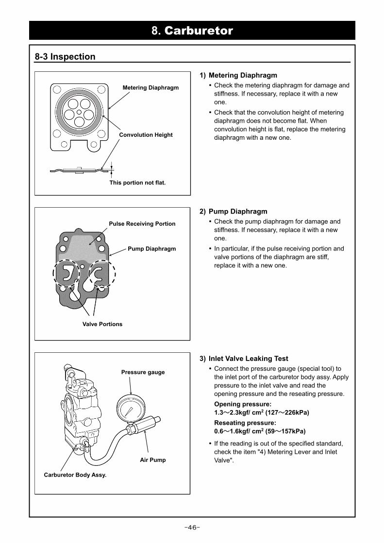
1) Metering Diaphragm
Check the metering diaphragm for damage and
stiffness. If necessary, replace it with a new
one.
Check that the convolution height of metering
diaphragm does not become flat. When
convolution height is flat, replace the metering
diaphragm with a new one.
2) Pump Diaphragm
Check the pump diaphragm for damage and
stiffness. If necessary, replace it with a new
one.
In particular, if the pulse receiving portion and
valve portions of the diaphragm are stiff,
replace it with a new one.
3) Inlet Valve Leaking Test
Connect the pressure gauge (special tool) to
the inlet port of the carburetor body assy. Apply
pressure to the inlet valve and read the
opening pressure and the reseating pressure.
Opening pressure:
1.3~2.3kgf/ cm2 (127~226kPa)
Reseating pressure:
0.6~1.6kgf/ cm2 (59~157kPa)
If the reading is out of the specified standard,
check the item "4) Metering Lever and Inlet
Valve".
Pressure gauge
Air Pump
Carburetor Body Assy.
This portion not flat.
Convolution Height
Metering Diaphragm
Valve Portions
Pump Diaphragm
Pulse Receiving Portion

-47-
8. Carburetor
8-3 Inspection
4) Metering Lever and Inlet Valve
Measure the metering lever height using a
depth gauge or scale.
Specified standard: 1.5±0.16mm
If the reading is out of the specified standard,
repair the metering lever or replace it with a
new one.
Check the wear of the contact portion of the
metering lever and the metering diaphragm. If
necessary, replace them with new parts.
Check the lever shaft, and if it is rusted replace
it with a new one.
Remove the inlet valve and check for dirt,
sludge, rusting and/or step-wear. Replace the
inlet valve if a beveled edge is found on the
rubber tip.
Inspect the clogging of the fuel passage in the
carburetor body and make sure there are no
dirt on the pump cover. If necessary, dip the
carburetor body and the pump cover in
gasoline for about 10 minutes, or clean them
using carburetor cleaner.
When setting the spring, be careful not to bend
it.
5) Screen
Inspect the screens for clogging, be sure to clean
if the dust is adhered.
Body Assy.
Metering Lever 1.5±0.16mm
Body
Assy.
Valve Seat
Lever Shaft
Inlet Valve
Check of the wear.
Metering Diaphragm
Step-wear
Not-good
Screen
Clogging
Bending of the spring.

-48-
8. Carburetor
8-3 Inspection
7) Main Check Valve
Make sure to check the main check valve in
case fuel is not supplied though the priming tic
when operated.
Press the vinyl pipe (inner diameter:φ5mm)
against the main check valve and blow and
suck with mouth.
[A]: Stop by blowing
[B]: Open by sucking
Main check valve has no failure.
In case of failure, soak the body assy. into
gasoline for about 10 minutes and repeat
blowing and sucking several times. If this is not
successful, replace the body assy.
NOTE:
Do not clean the main check valve with
compressed air. If the main check valve is
cleaned by compressed air, it may not
function properly.
8) H-needle
Remove the limiter cap with the limiter cap tool
(see page 50).
Remove the H-needle, check the wear and
damage of the tip and screw portions and if
necessary replace it with a new one.
Clean the clogging of the fuel passage of the
carburetor body. When cleaning, remove the
throttle valve and spray the carburetor cleaner
from the main nozzle side and the H-needle
mounting hole side.
NOTE:
In this carburetor, the fuel passage at the
tip of the needle is narrower than the
conventional carburetor. Therefore, to
prevent clogging, clean the passage
securely.
When using a fuel with a high mixing ratio
of oil, clogging is likely to be caused by oil
sludge and dust, so we recommend mixing
ratio gasoline 50 : FD registerde oil 1.
Plastic Pipe
Main Check Valve
H-needle
O-ring
Carburetor
Cleaner
Main
Nozzle
Body
H-needle Mounting Hole
Body Assy.
[A] [B]

-49-
8. Carburetor
8-3 Inspection
9) Gaskets
When assembling the new metering diaphragm
and the new pump diaphragm, be sure to replace
the gasket with new parts at the same time.
10) Throttle Valve
Check the wear of the plunger contact surface
of the throttle valve.Carefully move the thin tip
screwdriver along the slope of the plunger
contact surface and inspect for any grooves or
scratches where the tip of the screwdriver
catches. If there are grooves, replace the
throttle valve assy. with a new one..
11) Jet Needle
Check that no wear exists on the jet needle.If
there are signs of vertical linear flaws or wear,
replace the throttle valve assy. with a new one.
NOTE:
Even small damage affect fuel flow.
Jet Needle
Damage Wear
Throttle Valve Assy.
Contact Surface Plunger
New Gasket
New
Pump
Diaphragm
New gasket
New Metering Diaphragm

-50-
8. Carburetor
8-4 Adjustment
1) Limiter Cap Removal
Insert the threaded portion of the limiter cap tool
(special tool) into the hole of the throttle valve
and screw it counterclockwise while pressing it
against the limiter cap. Remove the L-needle
side limiter cap from the throttle valve by pulling
the limiter cap tool. Remove the H-needle side
limiter cap in the same way as the L-needle side
limiter cap.
NOTE:
If it is difficult to screw in the limiter cap tool,
firmly press the tool while screwing. When
threads are completely meshed, pull it out in
one stroke. If cap is damaged and stays in
the hole, use a pick type tool to remove it.
2) Initial Start Settings
① Turn the Idle adjustnment screw
counterclockwise (CCW) until its tip just
touches throttle valve stop, then turn it
clockwisely (CW) to the position where the
engine speed gets slightly higher.
② Turn the L-needle counterclockwise (CCW)
completely out until a “clicking sound” is
heard.
③ Then turn the L-needlein clockwise (CW) at
Basic Adjustment Turns.
NOTE:
Do not tighten the L-needle more than the
Basic Adjustment Turns. Tightening too
much may damage the needle spring and
L-needle.
Models Basic Adjustment Turns
WYA-236A (EBZ7500) 14
WYA-237A (EBZ8500) 14- 1/2
④ Turn the H-needle clockwise (CW) until very
gently seated.
⑤ Then turn the H-needle counterclockwise at
(CCW) Basic Adjustment Turns.
Model Basic Adjustment Turns
WYA-236A (EBZ7500) 1- 3/4±1/2
WYA -237A (EBZ8500) 2- 1/4±1/2
④
⑤
H-needle
② Driver
(Tip width: 2 mm)
③
L-needle
Idle Adjustment Screw
①
Limiter Cap Tool
(M2 left-threading)
L-needle
Limiter Cap
Driver
(Tip width: 2 mm)

-51-
8. Carburetor
8-4 Adjustment
3) Warm-up
Standard pipe and nozzle must be installed
properly. Start the engine and alternate three
times between the idling state (10 seconds) and
wide open throttle (60 seconds).
4) Low Speed Mixture Needle Adjustment
① Turn the L-needle clockwise (CW) or counter-
clockwise (CCW), to adjust so that the engine
speed is the maximum speed.
② Adjust the engine speed at Peak Idling rpm
with the idle adjustment screw.
Models Peak Idling (rpm)
WYA-236A (EBZ7500) 2,700±200
WYA-237A (EBZ8500) 2,700±100
③ Set the engine speed at 2,000±200 rpm by
turning the L-needle counterclockwise (CCW).
Models Rich Down (rpm)
WYA-236A (EBZ7500) 600~800
WYA-237A (EBZ8500) 700
NOTE:
In order to accurately measure the engine
speed, measure every time the L-needle is
adjusted about 10 seconds after the
engine speed stabilizes.
Rich Down:
Adjust the L-needle to a slightly richer
mixture in order to maintain a stable idling
speed and get a good acceleration.
①
L-needle
②
Idle Adjustment Screw
③
Target RPM
Rich Down
Co
ns
um
pti
on
L/h
2,000±200rpm Peak Idling
Engine speed (rpm)

-52-
8. Carburetor
8-4 Adjustment
5) High Speed Mixture Needle Adjustment
Accelerate engine to wide open throttle, adjust the
engine speed at Maximum Speed rpm by turning
the H-needle clockwise (CW).
Models Maximum Speed (rpm)
WYA-236A (EBZ7500) 7,100±200
WYA-237A (EBZ8500) 7,250±50
NOTE:
If the engine speed is too high,
acceleration failure and output will
decrease.
The ignition coil is digital control misfire
type, and when the engine speed is too
high, it may not be possible to display with
the tachometer.
6) Plug Installation
Push the plug (No.1881-81160) firmly into the
holes of the L-needle and H-needle using the
straight side of the limiter cap tool (special tool).
H-needle
Plug
Plug

-53-
9. Maintenance Standards/ Tightening Torques
9-1 Standards and Service Ability Limit
Maintenance Item Unit EBZ7500 EBZ8500 ※1
Measuring Procedure
Standard Limit Standard Limit
Cylinder
Compression pressure kgf/cm² (kPa)
8.4 5.6 8.4 5.6 CPG Cylinder/ Piston ring Replace.
Bore mm φ47.5 ※2 φ51 ※2 CG Expose of base
metal: Replace.
Piston
Piston skirt diameter mm φ47.454~φ
47.474 φ47.37
φ50.98~φ50.91
φ50.81 MM Replace.
Piston ring
groove width
Top mm
1.23 1.3 ← ← TG Replace.
2nd 1.21 1.3 ← ←
Piston pin hole mm φ12.005 φ12.045 ← ← CG Replace.
Clearance between
piston and cylinder mm
0.056~0.096
0.22 0.07~0.11
0.22 MM CG
Piston
Replace.
Clearance
between piston
groove and
piston ring
Top
mm
0.06~0.1 0.15 ← ←
TG Replace.
2nd 0.04~0.08 0.15 ← ←
Fitting between piston
pin and piston pin hole mm
0.005~0.021
0.05 ← ← MM CG
Replace.
Piston Ring End gap at cylinder skirt mm 0.15~0.35 0.6 ← ← TG Replace.
Width mm 1.2 1.1 ← ← MM Replace.
Piston Pin Diameter mm φ12 φ11.98 ← ← MM Replace.
Connecting Rod
Small end bore mm φ16 φ16.03 ← ← CG Replace.
Parallelism of large/ small
end bores 0
0.15/
100※3 ← ←
Mandrel DG
Replace.
Crankshaft
Diameter at
main bearing
MAG mm
φ16 φ15.95 ← ← MM Replace.
PTO φ16 φ15.95 ← ←
Diameter at oil seal
(MAG,PTO) mm φ16 φ15.9 ← ← MM Replace.
Eccentricity mm 0 0.06※4
(@ 6) ← ←
DG Center Support
Repair or replace.
Width between crank
webs mm 31
30.9~
31.1 ← ← MM Repair or replace.
Axial Play mm 0.071~0.369
0.5 0.057~0.383
0.5 TG Replace.
Main Bearing - - ※5 - ※5 - Replace.
※1 Meaning of abbreviations
CG:Cylinder Gauge/ MM:Micrometer/ DG:Dial Gauge/ TG:Thickness Gauge/ CPG:Compression gauge
※2 Peel off of plating or expose of base metal.
※3 length of the 100m, 0.05 or less
※4 Points from the crank web of 6mm
※5 Flutter, irregular noise generated

-54-
9. Maintenance Standards/ Tightening Torques
9-2 Tightening Torques
Tightening Item Thread size
(mm)
Tightening Torque
N・m (kgf・cm)
Engine
Spark Plug M10S×1.0 9~12 (90~130)
Muffler Upper: M6×30L
Lower: M6×16L 8~12 (80~120)
Diffuser M4×8L 2~3 (20~30)
Cylinder M5×22L 6~9 (60~90)
Cylinder Plate M5×8L 3~4 (30~40)
Crankcase M5×30L 6~8 (60~80)
Insulator M5×27L 4~6 (40~60)
Intake Cup/ Carburetor M5×60L 3~4.5 (30~45)
Recoil Starter M5×16L
(Apply 3M-2353 12mm) 3~4.5 (30~45)
Starter Pulley ━ 2.9~3.9 (30~40)
Rotor M10×1.0 (Hex nut) 25~35 (250~350)
Ignition Coil M4×22L 2.5~4 (25~40)
Coupling M10×1.0 (Hex nut) 25~35 (250~350)
Fuel Tank 5×12L 2.5~3.5 (20~35)
Engine Mount M6×50L 10~12 (100~120)
Guard Net/ Volute Cover/ Volute Case/ Engine Cover/ Cleaner 5 (1.81P-tight)×25L 3~4 (30~40)
Fan M6×26L 10~14 (100~140)
Upper Damper Left and right M5×16L (2) 2.5~3.5 (25~35)
Center M5×40L (1) 4~5 (40~50)
Lower Damper M6×1.0 (Hex nut) 4~6 (40~60)
Throttle Arm M5×16L 2.5~3.5 (25~35)
-55-
10. Troubleshooting
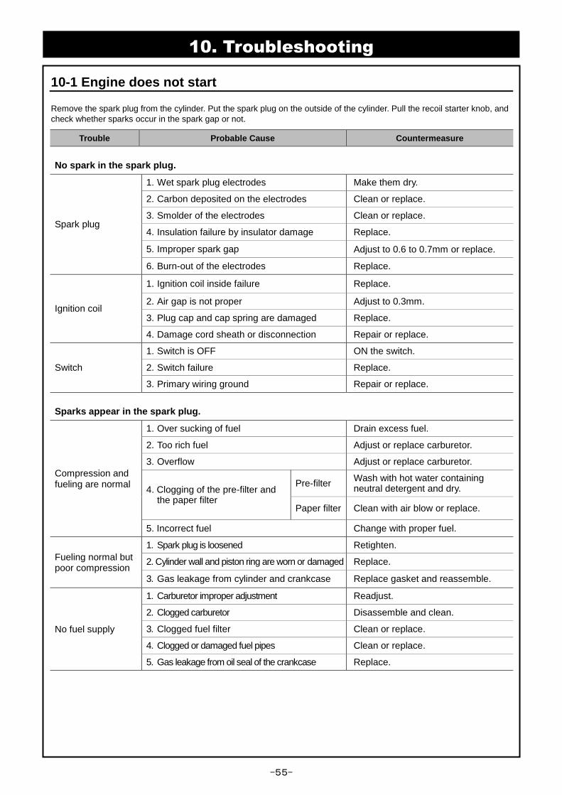
10-1 Engine does not start
Remove the spark plug from the cylinder. Put the spark plug on the outside of the cylinder. Pull the recoil starter knob, and
check whether sparks occur in the spark gap or not.
Trouble Probable Cause Countermeasure
No spark in the spark plug.
Spark plug
1. Wet spark plug electrodes Make them dry.
2. Carbon deposited on the electrodes Clean or replace.
3. Smolder of the electrodes Clean or replace.
4. Insulation failure by insulator damage Replace.
5. Improper spark gap Adjust to 0.6 to 0.7mm or replace.
6. Burn-out of the electrodes Replace.
Ignition coil
1. Ignition coil inside failure Replace.
2. Air gap is not proper Adjust to 0.3mm.
3. Plug cap and cap spring are damaged Replace.
4. Damage cord sheath or disconnection Repair or replace.
Switch
1. Switch is OFF ON the switch.
2. Switch failure Replace.
3. Primary wiring ground Repair or replace.
Sparks appear in the spark plug.
Compression and fueling are normal
1. Over sucking of fuel Drain excess fuel.
2. Too rich fuel Adjust or replace carburetor.
3. Overflow Adjust or replace carburetor.
4. Clogging of the pre-filter and the paper filter
Pre-filter Wash with hot water containing neutral detergent and dry.
Paper filter Clean with air blow or replace.
5. Incorrect fuel Change with proper fuel.
Fueling normal but poor compression
1. Spark plug is loosened Retighten.
2. Cylinder wall and piston ring are worn or damaged Replace.
3. Gas leakage from cylinder and crankcase Replace gasket and reassemble.
No fuel supply
1. Carburetor improper adjustment Readjust.
2. Clogged carburetor Disassemble and clean.
3. Clogged fuel filter Clean or replace.
4. Clogged or damaged fuel pipes Clean or replace.
5. Gas leakage from oil seal of the crankcase Replace.

-56-
10. Troubleshooting
10-2 Engine stop during operation
Trouble Probable Cause Countermeasure
Suddenly stopped.
1. Switch is OFF ON the switch.
2. Plug cap disconnect Connect properly.
3. Switch cord or high tension cord sheath worn out
Replace.
4. Air gap is not proper Adjust to 0.3mm
5. Ignition coil inside failure Replace.
6. Engine seizure Overhaul and replace damaged parts.
7. Clogged breather Clean.
Gradual speed reduction and stopped.
1. Lack of fuel Refill.
2. Clogged carburetor Disassemble and clean.
3. Water mixed with fuel Drain and apply new fuel.
Revolution rises suddenly and stops.
1. Lack of fuel Refill.
2. Clogged breather Clean.
3. Clogged carburetor Clean.
10-3 Engine cannot be stopped
Trouble Probable Cause Countermeasure
Overheating
1. Lean fuel Adjust or replace carburetor.
2. Cooling passage clogged with dusts Clean.
3. Cylinder fin clogged with dusts Clean.
4. Improper fuel Change with proper fuel.
5. Carbon deposited inside of combustion chamber
Clean.
6. Spark plug electrode red hot Clean thoroughly and adjust spark
gap to 0.6 to 0.7mm.
Ignition coil 1. Ignition coil inside failure Replace.
Switch 1. Switch failure Replace.
2. Cord failure Replace.

-57-
10. Troubleshooting
10-4 Lack of output power or unstable revolution
Trouble Probable Cause Countermeasure
Compression is normal and no misfire.
1. Air is entering at fuel pipe joints, Secure connections.
2. Air is entering at crack or pinhole of fuel pipe.
Replace.
3. Air is entering at insulator and carburetor mounting portion
Replace gasket and retighten.
4. Air is entering at oil seal Replace.
5. Water mixed with fuel Drain/ clean and apply new fuel.
6. Piston is starting to seize Filing of seized surface with fine files or replace.
7. Muffler clogged with carbon Clean.
Overheating
1. Lean fuel Adjust or replace carburetor.
2. Cooling passage clogged with dusts Clean.
3. Cylinder fin clogged with dusts Clean.
4. Improper fuel Change with proper fuel.
5. Carbon deposited inside of combustion chamber
Clean.
6. Spark plug electrode red hot Clean thoroughly and adjust spark gap to 0.6 to 0.7mm.
Others
1. Poor fuel quality Replace with clean fuel.
2. Clogged fuel filter Clean or replace.
3. Clogging of the pre-filter and the paper filter
Pre-filter Wash with hot water containing neutral detergent and dry.
Paper filter Clean with air blow or replace.
4. Muffler clogged with carbon Clean.
10-5 The amount of the wind is weak
Trouble Probable Cause Countermeasure
Good compression but cannot reach the required revolutions at full throttle
1. Clogging of the pre-filter and the paper filter
Pre-filter Wash with hot water containing neutral detergent and dry.
Paper filter Clean with air blow or replace.
2. Muffler clogged with carbon Clean.
3. Carburetor failure Maintenance or replace.

-58-
10. Troubleshooting
10-6 Others
Trouble Probable Cause Countermeasure
Poor fuel consumption
Clogging of the pre-filter and the paper filter
Pre-filter Wash with hot water containing neutral detergent and dry.
Paper filter Clean with air blow or replace.