eca 82 lonworks in the ecl comfort 300/301...
TRANSCRIPT
DH-SMT/DK VI.7F.C6.02 © Danfoss 05/2009 DH-SMT/DK VI.7F.C6.02 © Danfoss 05/2009
ECA 82LonWorks in the ECL Comfort 300/301
Instructions

VI.7F.C6.02 © Danfoss 05/2009 DH-SMT/DK
Instructions ECA 82 LonWorks in the ECL Comfort 300/301
Table of Contents
1 Introduction 11.1 Scope ..............................................................................................................................................................................................................................................11.2 About the implementation in the LonWorks protocol ................................................................................................................................................11.3 General information ..................................................................................................................................................................................................................11.4 ECA 82 compatibility with other optional cards .............................................................................................................................................................11.5 ECA 82 compatibility with the ECL Comfort controller and applications .............................................................................................................1
2 Getting started 22.1 Installation ....................................................................................................................................................................................................................................22.2 Starting up ....................................................................................................................................................................................................................................32.3 Service pin and neuron ID ......................................................................................................................................................................................................32.4 XIF file and program ID ............................................................................................................................................................................................................4
3 Node object 53.1 Mandatory network variables ...............................................................................................................................................................................................53.1.1 Network variable 1. Node request: Input ..........................................................................................................................................................................53.1.2 Network variable 3. Setting time and date: Input ..........................................................................................................................................................63.1.3 Network variable 2. Node status: Output .........................................................................................................................................................................73.1.4 Network variable 4. Alarm: Output ......................................................................................................................................................................................7
4 Weather compensator object 94.1 Network variables 5. & 11. Setpoints, circuit I & II: Input ............................................................................................................................................104.2 Network variable 8. Setpoints, hot water setting: Input ...........................................................................................................................................104.3 Network variables 15. & 16. & 59. Control of valves and mode: Input ...................................................................................................................114.4 Network variable 21. Control of pumps: Input ..............................................................................................................................................................114.5 Network variable 55. Control of the week plan ............................................................................................................................................................124.6 Network variables 34. & 36. Actual power input from node in the network. Input ........................................................................................134.7 Network variables 36. & 37. Actual flow input from a node in the network. Input ..........................................................................................144.8 Handling energy and flow input from the network ....................................................................................................................................................144.8.1 Setting time constants ...........................................................................................................................................................................................................144.8.2 Setting the flow or energy reference ................................................................................................................................................................................154.9 Network variable 53. Outdoor temperature input ......................................................................................................................................................154.10 Network variable 54. Outdoor temperature input ......................................................................................................................................................164.11 General handling of outdoor temperature input ........................................................................................................................................................164.12 Network variables 6. 7. & 17.-20. & 46.–49. Temperature sensors 1-10: Output .................................................................................................164.13 Network variables 9. & 12. Setpoint concerning circuit I & II: Output ...................................................................................................................174.14 Network variable 10. Setpoints concerning hotwater setting: Output ...............................................................................................................174.15 Network variables 13. & 14. & 61. Status of valves, optimizer status and relative ............................................................................................18 humidity ......................................................................................................................................................................................................................................184.16 Network variable 22. Reading off time and date: Output .........................................................................................................................................194.17 Network variable 33. Pump status ....................................................................................................................................................................................194.18 Network variable 56. Reporting week plan in ECL Comfort. Output ....................................................................................................................194.19 Network variables 57. & 58. & 60. Controller mode status, circuit I & II & III. Output ...................................................................................... 204.20 Network variables 42. & 43. Actual power delivered from pulse module. Output ......................................................................................... 204.21 Network variables 44. & 45. Actual flow delivered from pulse module. Output ............................................................................................. 204.22 Network variables 27. – 30. Sensor references 3-6. Output ......................................................................................................................................21

DH-SMT/DK VI.7F.C6.02 © Danfoss 05/2009
Instructions ECA 82 LonWorks in the ECL Comfort 300/301
5 Manufacturer-defined section 225.1 Network variables 23. & 24. Analog outputs 1 & 2: Input ......................................................................................................................................... 225.2 Network variables 25. & 26. Analog inputs 1 & 2: Output ........................................................................................................................................ 235.3 Network variables 19. & 20. Parameter command and response .......................................................................................................................... 235.3.1 Learn field................................................................................................................................................................................................................................... 235.3.2 Selector field ..............................................................................................................................................................................................................................245.3.3 Value field ....................................................................................................................................................................................................................................245.3.4 Parameters, grey side of the ECL card, circuit I ..............................................................................................................................................................265.3.5 Parameters, yellow side of the ECL card, circuit I. ....................................................................................................................................................... 285.3.6 Parameters, grey side of the ECL card, circuit II ........................................................................................................................................................... 295.3.7 Parameters, yellow side of the ECL card, circuit II ....................................................................................................................................................... 305.3.8 Parameters, gray side of the ECL card, circuit III ...........................................................................................................................................................315.3.9 ECL Comfort status information .........................................................................................................................................................................................315.3.9.1 Selector 250 details .................................................................................................................................................................................................................315.3.9.2 Selector 251 details .................................................................................................................................................................................................................315.3.9.3 Selector 252 details .................................................................................................................................................................................................................315.3.10 ECA 82 set-up and details ......................................................................................................................................................................................................325.3.10.1 Software version in ECA 82 ...................................................................................................................................................................................................325.3.10.2 SendHeartBeat ..........................................................................................................................................................................................................................325.3.10.3 Voltage update ..........................................................................................................................................................................................................................325.3.10.4 ECL checks for adjustments..................................................................................................................................................................................................325.3.10.5 Application loaded in the ECL Comfort ...........................................................................................................................................................................325.3.11 Alarm limit configuration ......................................................................................................................................................................................................325.3.12 Alarm code readout.................................................................................................................................................................................................................335.3.13 Accumulated energy or flow preload ...............................................................................................................................................................................33
6 Thumb rules for network design in heating systems 356.1 Considerations before implementing communication .............................................................................................................................................356.1.1 What are the basic needs for information ......................................................................................................................................................................356.1.2 What is the final number of nodes in the network ..................................................................................................................................................... 366.1.2.1 Parallel network ....................................................................................................................................................................................................................... 366.1.2.2 Backbone network .................................................................................................................................................................................................................. 366.1.3 Bandwidth considerations ................................................................................................................................................................................................... 366.1.3.1 Total number of controllers in network .......................................................................................................................................................................... 386.2 Update of SNVT from ECL Comfort ....................................................................................................................................................................................396.2.1 Minimize copy of data on the network ............................................................................................................................................................................396.2.2 Note down the neuron ID .....................................................................................................................................................................................................39
DH-SMT/DK VI.7F.C6.02 © Danfoss 05/2009 1
Instructions ECA 82 LonWorks in the ECL Comfort 300/301
1 Introduction
1.1 ScopeThis ECA 82 option for ECL Comfort is based on Echelons® LonWorks®. The ECA 82 can be used in ECL Comfort 300/301 series. In the remaining part of these instructions, the type designation ECL Comfort will be used.
1.2 About the implementation in the LonWorks protocolThe following instruction describes the parameters that can be communicated between a LonWorks network and ECL Comfort. The build-up of the physical network is not described. For further information see Echelons homepage: http://www.echelon.com/.
The instruction is divided into three main sections:
1. The LonMark node object is used to the extent that functions are supported in ECL Comfort. The functions from the node object that are supported in ECL Comfort are described in “Node object”.
2. The basic parameters behind weather compensation are described separately in the section on the weather compensator object.
3. Parameters that are special for ECL Comfort are described separately in the manufacture-defined section.
1.3 General information1. The possibilities for communication depend on the application loaded in the ECL Comfort. This ECA
82 is designed to fit all ECL Comfort 300/301 application cards. Hardware configuration settings and future parameters might not be supported.
2. Only one kind of communication can be used in the ECL Comfort. It is not possible to run RS232 together with ECA 82 communication.
1.4 ECA 82 compatibility with other optional modules
ECA 71 ECA 73 ECA 80 ECA 81 ECA 83 ECA 84 ECA 86 ECA 87 ECA 88No No Yes No Yes No Yes No Yes
1.5 ECA 82 compatibility with the ECL Comfort controller and applicationsECA 82 is fully compatible with ECL Comfort controllers 300/301 as of version 1.11. Older ECL Comfort controllers versions are also compatible with ECA 82 but in some cases with limited functionality.

2 VI.7F.C6.02 © Danfoss 05/2009 DH-SMT/DK
Instructions ECA 82 LonWorks in the ECL Comfort 300/301
2 Getting started The ECA 82 can be used together with ECL Comfort 300 and 301. It is not possible to use the ECA 82 together with ECL Comfort 100/110/200.
Further information on the operation of ECL Comfort is comprised by the instructions supplied with the ECL Card.
2.1 InstallationStep 1: Dismount cover plate B on the back of the ECL Comfort using a small slice cutter nipper.
Step 2:Mount ECA 82 in the slides and press it gently into the connector on the ECL Comfort print board.
Step 3:Mount the new cover plate B, which is delivered with the option card.
DH-SMT/DK VI.7F.C6.02 © Danfoss 05/2009 3
Instructions ECA 82 LonWorks in the ECL Comfort 300/301
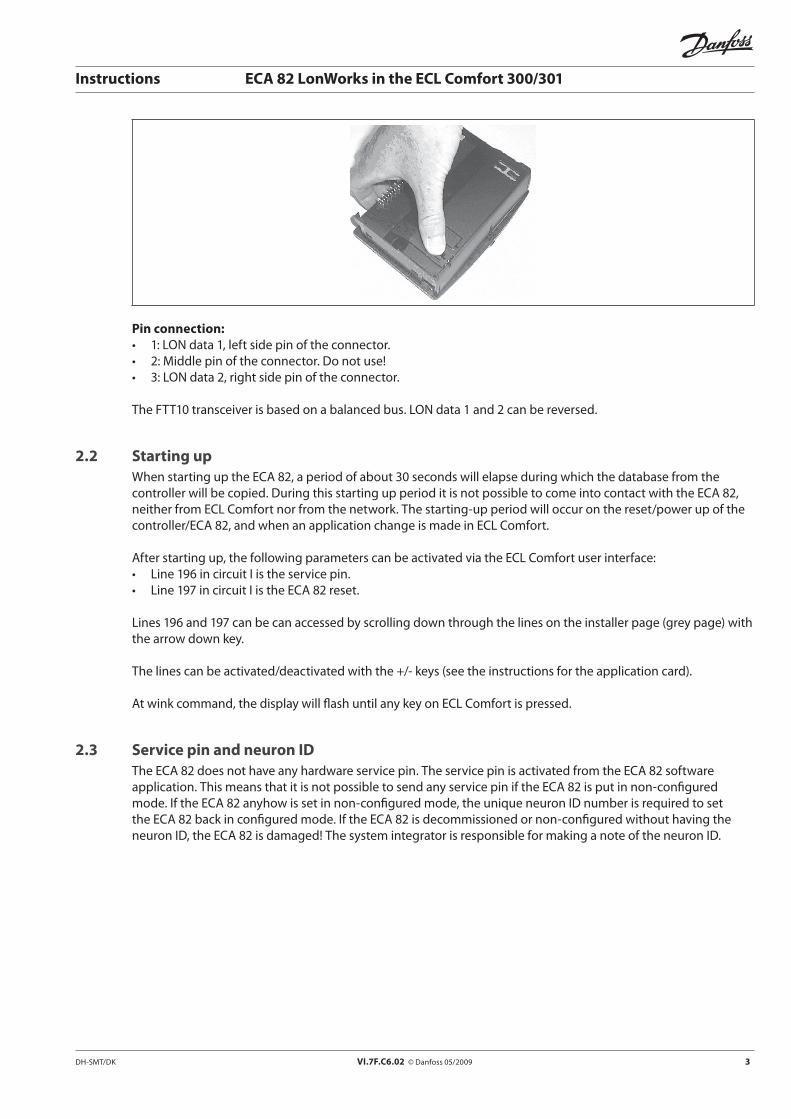
Pin connection:• 1:LONdata1,leftsidepinoftheconnector.• 2:Middlepinoftheconnector.Donotuse!• 3:LONdata2,rightsidepinoftheconnector.
The FTT10 transceiver is based on a balanced bus. LON data 1 and 2 can be reversed.
2.2 Starting upWhen starting up the ECA 82, a period of about 30 seconds will elapse during which the database from the controller will be copied. During this starting up period it is not possible to come into contact with the ECA 82, neither from ECL Comfort nor from the network. The starting-up period will occur on the reset/power up of the controller/ECA 82, and when an application change is made in ECL Comfort.
After starting up, the following parameters can be activated via the ECL Comfort user interface: • Line196incircuitIistheservicepin.• Line197incircuitIistheECA82reset.
Lines 196 and 197 can be can accessed by scrolling down through the lines on the installer page (grey page) with the arrow down key.
The lines can be activated/deactivated with the +/- keys (see the instructions for the application card).
At wink command, the display will flash until any key on ECL Comfort is pressed.
2.3 Service pin and neuron IDThe ECA 82 does not have any hardware service pin. The service pin is activated from the ECA 82 software application. This means that it is not possible to send any service pin if the ECA 82 is put in non-configured mode. If the ECA 82 anyhow is set in non-configured mode, the unique neuron ID number is required to set the ECA 82 back in configured mode. If the ECA 82 is decommissioned or non-configured without having the neuronID,theECA82isdamaged!ThesystemintegratorisresponsibleformakinganoteoftheneuronID.
4 VI.7F.C6.02 © Danfoss 05/2009 DH-SMT/DK
Instructions ECA 82 LonWorks in the ECL Comfort 300/301
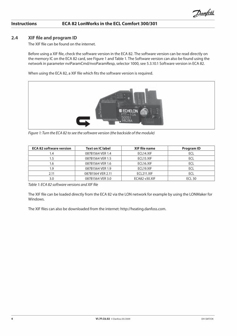
2.4 XIF file and program IDThe XIF file can be found on the internet.
Before using a XIF file, check the software version in the ECA 82. The software version can be read directly on the memory IC on the ECA 82 card, see Figure 1 and Table 1. The Software version can also be found using the network in parameter nviParamCmd/nvoParamResp, selector 1000, see 5.3.10.1 Software version in ECA 82.
When using the ECA 82, a XIF file which fits the software version is required.
Figure 1: Turn the ECA 82 to see the software version (the backside of the module)
ECA 82 software version Text on IC label XIF file name Program ID1.4 087B1564 VER 1.4 ECL14.XIF ECL1.5 087B1564 VER 1.5 ECL15.XIF ECL1.6 087B1564 VER 1.6 ECL16.XIF ECL1.9 087B1564 VER 1.9 ECL19.XIF ECL
2.11 087B1564 VER 2.11 ECL211.XIF ECL3.0 087B1564 VER 3.0 ECA82 v30.XIF ECL 30
Table 1: ECA 82 software versions and XIF file
The XIF file can be loaded directly from the ECA 82 via the LON network for example by using the LONMaker for Windows.
The XIF files can also be downloaded from the internet: http://heating.danfoss.com.

DH-SMT/DK VI.7F.C6.02 © Danfoss 05/2009 5
Instructions ECA 82 LonWorks in the ECL Comfort 300/301
3 Node objectThe node object is used for controlling and establishing the status of the node. It is thus possible to ask for and receive the status of the actual condition of the node.
Mandatory Nework variables
Optional network variables
Input Network Variables
Output Network Variables Node Object
Type #0
nv 2 nvoStatus SNVT_obj_status
nv 1 nviRequest SNVT_obj_request
nv 4 nvoAlarm SNVT_alarm
nv 3 nviTimeSet SNVT_time_stamp
Figure 2: Node object
NV NR Name SNVT Type(SNVT Index)
Class Description
1 NviRequest SNVT_obj_request Ram Request object status3 NviTimeSet SNVT_time_stamp Ram Set time and date
Table 2: SNVT input
NV NR Name SNVT Type(SNVT Index)
Class Description
2 NvoStatus SNVT_obj_status Ram Status of node
4 NvoAlarm SNVT_Alarm Ram Alarm reporting
Table 3: SNVT output
3.1 Mandatory network variables
3.1.1 Network variable 1. Node request: Inputnetwork input SNVT_obj_request nviRequest;
6 VI.7F.C6.02 © Danfoss 05/2009 DH-SMT/DK
Instructions ECA 82 LonWorks in the ECL Comfort 300/301
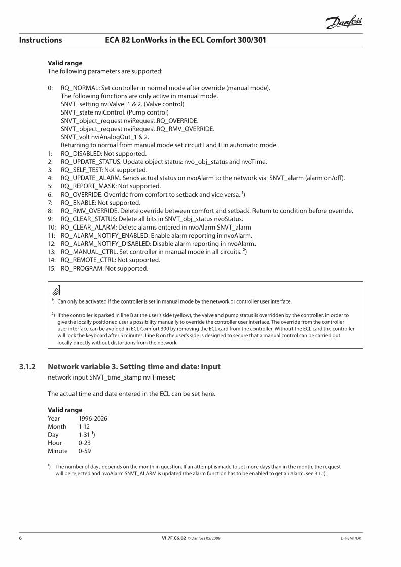
Valid rangeThe following parameters are supported:
0: RQ_NORMAL: Set controller in normal mode after override (manual mode). The following functions are only active in manual mode. SNVT_setting nviValve_1 & 2. (Valve control) SNVT_state nviControl. (Pump control) SNVT_object_request nviRequest.RQ_OVERRIDE. SNVT_object_request nviRequest.RQ_RMV_OVERRIDE. SNVT_volt nviAnalogOut_1 & 2. Returning to normal from manual mode set circuit I and II in automatic mode.1: RQ_DISABLED: Not supported.2: RQ_UPDATE_STATUS. Update object status: nvo_obj_status and nvoTime.3: RQ_SELF_TEST: Not supported.4: RQ_UPDATE_ALARM. Sends actual status on nvoAlarm to the network via SNVT_alarm (alarm on/off).5: RQ_REPORT_MASK: Not supported.6: RQ_OVERRIDE. Override from comfort to setback and vice versa. ¹)7: RQ_ENABLE: Not supported.8: RQ_RMV_OVERRIDE. Delete override between comfort and setback. Return to condition before override.9: RQ_CLEAR_STATUS: Delete all bits in SNVT_obj_status nvoStatus.10: RQ_CLEAR_ALARM: Delete alarms entered in nvoAlarm SNVT_alarm11: RQ_ALARM_NOTIFY_ENABLED: Enable alarm reporting in nvoAlarm.12: RQ_ALARM_NOTIFY_DISABLED: Disable alarm reporting in nvoAlarm.13: RQ_MANUAL_CTRL. Set controller in manual mode in all circuits. ²)14: RQ_REMOTE_CTRL: Not supported.15: RQ_PROGRAM: Not supported.
¹) Can only be activated if the controller is set in manual mode by the network or controller user interface.
²) If the controller is parked in line B at the user’s side (yellow), the valve and pump status is overridden by the controller, in order to give the locally positioned user a possibility manually to override the controller user interface. The override from the controller user interface can be avoided in ECL Comfort 300 by removing the ECL card from the controller. Without the ECL card the controller will lock the keyboard after 5 minutes. Line B on the user’s side is designed to secure that a manual control can be carried out locally directly without distortions from the network.
3.1.2 Network variable 3. Setting time and date: Inputnetwork input SNVT_time_stamp nviTimeset;
The actual time and date entered in the ECL can be set here.
Valid rangeYear 1996-2026Month 1-12Day 1-31 ¹)Hour 0-23Minute 0-59
¹) The number of days depends on the month in question. If an attempt is made to set more days than in the month, the request will be rejected and nvoAlarm SNVT_ALARM is updated (the alarm function has to be enabled to get an alarm, see 3.1.1).

DH-SMT/DK VI.7F.C6.02 © Danfoss 05/2009 7
Instructions ECA 82 LonWorks in the ECL Comfort 300/301
3.1.3 Network variable 2. Node status: Outputnetwork output SNVT_obj_status nvoStatus;
SNVT uses this input to report on the node status.
The following points are supported:• Over_range: Set if an input value from the network is higher than the max permissible value.• Under_range: Set if an input value from the network is under the min permissible value.• Manual_control: Set if the controller has been set in manual mode from the network, or if the
controller is set in manual mode from ECL Comfort user interface.• In_alarm: Set if an alarm has been set.• In_override: Set if the controller overrides between comfort/setback from the network.• alarm_notify_disabled: Alarm reporting in nvoAlarm disabled.
3.1.4 Network variable 4. Alarm: Outputnetwork output SNVT_Alarm nvoAlarm;
The possibilities for alarm reporting are:
• Inputvalueoutofrangealarm.• Alarmonallphysicalsensors• Alarmsensor-reference2-8.• Alarmonrelativehumiditylevel.• Bitreportingof32alarmconditions.• Indicationofsensor-referencealarmontime:0min,10min,30minand60min• Timeanddateforlatestalarmoccurrence.• Historybufferwiththelatest4occurredSNVTalarmindexes.
The alarm function is enabled from nviRequest.RQ_ALARM_NOTIFY_ENABLE and disabled from nviRequest.RQ_ALARM_NOTIFY_DISABLE
All alarm levels are configured in 5.3.11 Alarm limit configuration
If an illegal date or year is entered via nviTimeSet SNVT_time_stamp, an alarm type 1 will be activated and the year or day will show the illegal value.
Alarm type:Value Identifier Notes0 AL_NO_CONDITION No alarm condition present1 AL_ALM_CONDITION Invalid value set in nviTimeset9 AL_LOW_LMT_ALM_1 Alarm low limit alarm 1: Attempt to set parameter under legal value10 AL_LOW_LMT_ALM_2 Alarm low limit alarm 2: Value under configured level has expired11 AL_HIGH_LMT_ALM_1 Alarm high limits alarm 1: Attempt to set parameter higher than legal value 12 AL_HIGH_LMT_ALM_2 Alarm high limits alarm 2: Value higher than configured level has expired0xFF AL_NUL Value not available
8 VI.7F.C6.02 © Danfoss 05/2009 DH-SMT/DK
Instructions ECA 82 LonWorks in the ECL Comfort 300/301
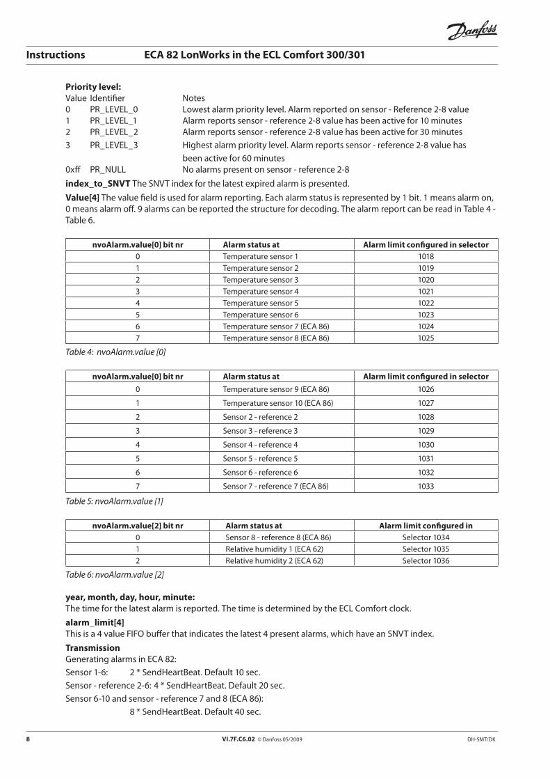
Priority level:Value Identifier Notes0 PR_LEVEL_0 Lowest alarm priority level. Alarm reported on sensor - Reference 2-8 value1 PR_LEVEL_1 Alarm reports sensor - reference 2-8 value has been active for 10 minutes2 PR_LEVEL_2 Alarm reports sensor - reference 2-8 value has been active for 30 minutes3 PR_LEVEL_3 Highest alarm priority level. Alarm reports sensor - reference 2-8 value has
been active for 60 minutes0xff PR_NULL No alarms present on sensor - reference 2-8
index_to_SNVT The SNVT index for the latest expired alarm is presented.
Value[4] The value field is used for alarm reporting. Each alarm status is represented by 1 bit. 1 means alarm on, 0 means alarm off. 9 alarms can be reported the structure for decoding. The alarm report can be read in Table 4 -Table 6.
nvoAlarm.value[0] bit nr Alarm status at Alarm limit configured in selector0 Temperature sensor 1 10181 Temperature sensor 2 10192 Temperature sensor 3 10203 Temperature sensor 4 10214 Temperature sensor 5 10225 Temperature sensor 6 10236 Temperature sensor 7 (ECA 86) 10247 Temperature sensor 8 (ECA 86) 1025
Table 4: nvoAlarm.value [0]
nvoAlarm.value[0] bit nr Alarm status at Alarm limit configured in selector
0 Temperature sensor 9 (ECA 86) 1026
1 Temperature sensor 10 (ECA 86) 1027
2 Sensor 2 - reference 2 1028
3 Sensor 3 - reference 3 1029
4 Sensor 4 - reference 4 1030
5 Sensor 5 - reference 5 1031
6 Sensor 6 - reference 6 1032
7 Sensor 7 - reference 7 (ECA 86) 1033
Table 5: nvoAlarm.value [1]
nvoAlarm.value[2] bit nr Alarm status at Alarm limit configured in0 Sensor 8 - reference 8 (ECA 86) Selector 10341 Relative humidity 1 (ECA 62) Selector 10352 Relative humidity 2 (ECA 62) Selector 1036
Table 6: nvoAlarm.value [2]
year, month, day, hour, minute:The time for the latest alarm is reported. The time is determined by the ECL Comfort clock.
alarm_limit[4]This is a 4 value FIFO buffer that indicates the latest 4 present alarms, which have an SNVT index.
TransmissionGenerating alarms in ECA 82:Sensor 1-6: 2 * SendHeartBeat. Default 10 sec.Sensor - reference 2-6: 4 * SendHeartBeat. Default 20 sec.Sensor 6-10 and sensor - reference 7 and 8 (ECA 86): 8 * SendHeartBeat. Default 40 sec.
DH-SMT/DK VI.7F.C6.02 © Danfoss 05/2009 9
Instructions ECA 82 LonWorks in the ECL Comfort 300/301
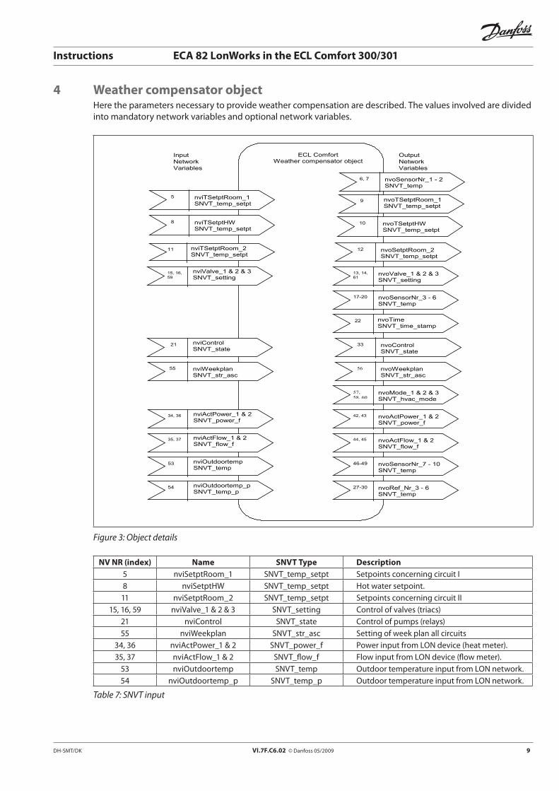
4 Weather compensator objectHere the parameters necessary to provide weather compensation are described. The values involved are divided into mandatory network variables and optional network variables.
5 nviTSetptRoom_1 SNVT_temp_setpt
15, 16, 59
nviValve_1 & 2 & 3 SNVT_setting
Input Network Variables
Output Network Variables
ECL Comfort Weather compensator object
22 nvoTime SNVT_time_stamp
11 nviTSetptRoom_2 SNVT_temp_setpt
9 nvoTSetptRoom_1 SNVT_temp_setpt
17-20 nvoSensorNr_3 - 6 SNVT_temp
8 nviTSetptHW SNVT_temp_setpt
10 nvoTSetptHW SNVT_temp_setpt
6, 7 nvoSensorNr_1 - 2 SNVT_temp
12 nvoSetptRoom_2 SNVT_temp_setpt
21
nviControl SNVT_state
56 nvoWeekplan SNVT_str_asc
33
nvoControl SNVT_state
55 nviWeekplan SNVT_str_asc
34, 36
nviActPower_1 & 2 SNVT_power_f
13, 14, 61
nvoValve_1 & 2 & 3 SNVT_setting
35, 37
nviActFlow_1 & 2 SNVT_flow_f
42, 43 nvoActPower_1 & 2 SNVT_power_f
44, 45 nvoActFlow_1 & 2 SNVT_flow_f
46-49 nvoSensorNr_7 - 10 SNVT_temp
27-30 nvoRef_Nr_3 - 6 SNVT_temp
53 nviOutdoortemp SNVT_temp
54
nviOutdoortemp_p SNVT_temp_p
57, 58, 60
nvoMode_1 & 2 & 3 SNVT_hvac_mode
Figure 3: Object details
NV NR (index) Name SNVT Type Description5 nviSetptRoom_1 SNVT_temp_setpt Setpoints concerning circuit I8 nviSetptHW SNVT_temp_setpt Hot water setpoint.11 nviSetptRoom_2 SNVT_temp_setpt Setpoints concerning circuit II
15, 16, 59 nviValve_1 & 2 & 3 SNVT_setting Control of valves (triacs)21 nviControl SNVT_state Control of pumps (relays)55 nviWeekplan SNVT_str_asc Setting of week plan all circuits
34, 36 nviActPower_1 & 2 SNVT_power_f Power input from LON device (heat meter).35, 37 nviActFlow_1 & 2 SNVT_flow_f Flow input from LON device (flow meter).
53 nviOutdoortemp SNVT_temp Outdoor temperature input from LON network.54 nviOutdoortemp_p SNVT_temp_p Outdoor temperature input from LON network.
Table 7: SNVT input

10 VI.7F.C6.02 © Danfoss 05/2009 DH-SMT/DK
Instructions ECA 82 LonWorks in the ECL Comfort 300/301
NV NR (index)
Name SNVT Type Send Heart Beat
Description
6, 7 nvoSensorNr_1–2 SNVT_temp *2 Sensor values9 nvoTSetptRoom_1 SNVT_temp_setpt No Setpoints, circuit I
10 nvoTSetptHW SNVT_temp_setpt No Setpoints, hot water.12 nvoTSetptRoom_2 SNVT_temp_setpt No Setpoints, circuit II.
13, 14, 61 nvoValve_1 & 2 & 3 SNVT_setting 5 sec Status of valves up/down/stopped.17-20 nvoSensorNr_3–6 SNVT_temp *2 Sensor values 3-6.
22 nvoTime SNVT_time_stamp *8 Time and date set in ECL Comfort33 nvoControl SNVT_state 5 sec Status of pumps (relays).56 nvoWeekplan SNVT_str_asc No Week plan setting, all circuits.
57, 58, 60 nvoMode_1 & 2 & 3 SNVT_hvac_mode 5 sec Controller mode, circuit I & II42, 43 nvoActPower_1& 2 SNVT_power_f *8 Actual power44, 45 nvoActFlow_1 & 2 SNVT_flow_f *8 Actual flow 46-49 nvoSensorNr_7-10 SNVT_temp *8 Sensor values from ECA 8627-30 nvoRef_Nr_3-6 SNVT_temp *4 References for sensor 3-6.
Table 8: SNVT output details
The SendHeartBeat value can be adjusted in 5.3.10.2, page 32.
4.1 Network variables 5. & 11. Setpoints, circuit I & II: Inputnetwork input SNVT_temp_setpt nviTSetptRoom_1;network input SNVT_temp_setpt nviTSetptRoom_2;
Field definitionsField Parameter Valid Range Resolutionoccupied_cool Proportional band 1.00 .. 250.00 K 1.00 standby_cool Parallel displacement -9.00 .. 9.00 K 1.00 unoccupied_cool Heating cut-out 10.00 .. 30.00 oC 1.00occupied_heat Setpoint comfort period 10.00 .. 30.00 oC 1.00 standby_heat Heat curve 0.20 .. 3.40 0.10 unoccupied_heat Setpoint setback period 10.00 .. 30.00 oC 1.00
Validation of dataIf input is set to a value outside the valid area, the setting is ignored in ECL Comfort and nvoTSetptRoom_1 or 2. The error is reported in nvoStatus.under_range / over_range.
Default valueDefault value set in the SNVT: All fields = 0 at start-up.
4.2 Network variable 8. Setpoints, hot water setting: Inputnetwork input SNVT_temp_setpt nviTSetptHW;
DH-SMT/DK VI.7F.C6.02 © Danfoss 05/2009 11
Instructions ECA 82 LonWorks in the ECL Comfort 300/301
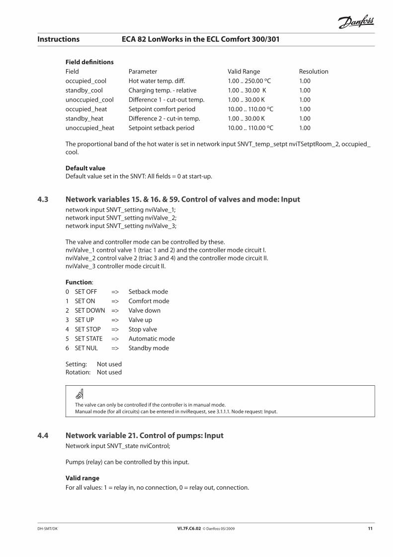
Field definitionsField Parameter Valid Range Resolutionoccupied_cool Hot water temp. diff. 1.00 .. 250.00 oC 1.00 standby_cool Charging temp. - relative 1.00 .. 30.00 K 1.00 unoccupied_cool Difference 1 - cut-out temp. 1.00 .. 30.00 K 1.00occupied_heat Setpoint comfort period 10.00 .. 110.00 oC 1.00 standby_heat Difference 2 - cut-in temp. 1.00 .. 30.00 K 1.00 unoccupied_heat Setpoint setback period 10.00 .. 110.00 oC 1.00
The proportional band of the hot water is set in network input SNVT_temp_setpt nviTSetptRoom_2, occupied_cool.
Default valueDefault value set in the SNVT: All fields = 0 at start-up.
4.3 Network variables 15. & 16. & 59. Control of valves and mode: Inputnetwork input SNVT_setting nviValve_1;network input SNVT_setting nviValve_2; network input SNVT_setting nviValve_3;
The valve and controller mode can be controlled by these. nviValve_1 control valve 1 (triac 1 and 2) and the controller mode circuit I.nviValve_2 control valve 2 (triac 3 and 4) and the controller mode circuit II.nviValve_3 controller mode circuit II.
Function:0 SET OFF => Setback mode 1 SET ON => Comfort mode 2 SET DOWN => Valve down 3 SET UP => Valve up 4 SET STOP => Stop valve 5 SET STATE => Automatic mode 6 SET NUL => Standby mode
Setting: Not usedRotation: Not used
The valve can only be controlled if the controller is in manual mode.Manual mode (for all circuits) can be entered in nviRequest, see 3.1.1.1. Node request: Input.
4.4 Network variable 21. Control of pumps: InputNetwork input SNVT_state nviControl;
Pumps (relay) can be controlled by this input.
Valid rangeFor all values: 1 = relay in, no connection, 0 = relay out, connection.

12 VI.7F.C6.02 © Danfoss 05/2009 DH-SMT/DK
Instructions ECA 82 LonWorks in the ECL Comfort 300/301
Bit 0: Standard relay 1 Bit 1: Standard relay 2Bit 2: Standard relay 3Other values are not supported.
Relays placed on optional cards (ECA 80 & ECA 86) cannot be controlled from the ECA 82. The application in ECL Comfort always control optional relays.
The pumps can only be controlled if the controller is in manual mode.Manual mode (for all circuits) can be entered in nviRequest, see 3.1.1.1. Node request: Input page 9 or directly at the ECL Comfort.In some applications the ECL Comfort overwrites the specified setting from the network. In sequence controllers (C75) non-valid relay combinations are overwritten by the ECL Comfort. Do not use this override function in the applications F05 and F06.
4.5 Network variable 55. Control of the week plannetwork input SNVT_str_asc nviWeekplan;
A new week plan can be set and the actual week plan already set in the controller can be requested. Request status of the week plan already set in controller for readout in nvoWeekplan.
Field ascii[0] - ascii[29] must contain the value 0x00;Field ascii[30] must contain an value indicating which week plan to report.
Field ascii[30] value Week plan area0x10 Week days in circuit I0x11 Weekend in circuit I0x20 Week days in circuit II0x21 Weekend in circuit II and all days circuit III
Table 9: Request week plan setting
The week plan is divided into ½ hour intervals. The week plan can contain a maximum of 3 periods a day. Each field ascii[0] - [29] is a char build of 8 bit. Each of these bits represent ½ hour in the week plan. The exact position can be found using Table 10.
DH-SMT/DK VI.7F.C6.02 © Danfoss 05/2009 13
Instructions ECA 82 LonWorks in the ECL Comfort 300/301
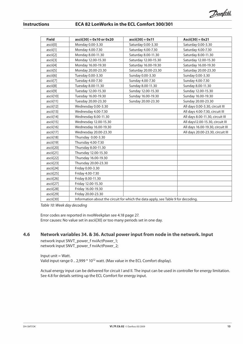
Field ascii[30] = 0x10 or 0x20 ascii[30] = 0x11 Ascii[30] = 0x21 ascii[0] Monday 0.00-3.30 Saturday 0.00-3.30 Saturday 0.00-3.30ascii[1] Monday 4.00-7.30 Saturday 4.00-7.30 Saturday 4.00-7.30ascii[2] Monday 8.00-11.30 Saturday 8.00-11.30 Saturday 8.00-11.30 ascii[3] Monday 12.00-15.30 Saturday 12.00-15.30 Saturday 12.00-15.30ascii[4] Monday 16.00-19.30 Saturday 16.00-19.30 Saturday 16.00-19.30ascii[5] Monday 20.00-23.30 Saturday 20.00-23.30 Saturday 20.00-23.30ascii[6] Tuesday 0.00-3.30 Sunday 0.00-3.30 Sunday 0.00-3.30ascii[7] Tuesday 4.00-7.30 Sunday 4.00-7.30 Sunday 4.00-7.30ascii[8] Tuesday 8.00-11.30 Sunday 8.00-11.30 Sunday 8.00-11.30 ascii[9] Tuesday 12.00-15.30 Sunday 12.00-15.30 Sunday 12.00-15.30ascii[10] Tuesday 16.00-19.30 Sunday 16.00-19.30 Sunday 16.00-19.30ascii[11] Tuesday 20.00-23.30 Sunday 20.00-23.30 Sunday 20.00-23.30ascii[12] Wednesday 0.00-3.30 All days 0.00-3.30, circuit IIIascii[13] Wednesday 4.00-7.30 All days 4.00-7.30, circuit IIIascii[14] Wednesday 8.00-11.30 All days 8.00-11.30, circuit III ascii[15] Wednesday 12.00-15.30 All days12.00-15.30, circuit IIIascii[16] Wednesday 16.00-19.30 All days 16.00-19.30, circuit IIIascii[17] Wednesday 20.00-23.30 All days 20.00-23.30, circuit IIIascii[18] Thursday 0.00-3.30ascii[19] Thursday 4.00-7.30ascii[20] Thursday 8.00-11.30 ascii[21] Thursday 12.00-15.30ascii[22] Thursday 16.00-19.30ascii[23] Thursday 20.00-23.30ascii[24] Friday 0.00-3.30ascii[25] Friday 4.00-7.30ascii[26] Friday 8.00-11.30 ascii[27] Friday 12.00-15.30ascii[28] Friday 16.00-19.30ascii[29] Friday 20.00-23.30ascii[30] Information about the circuit for which the data apply, see Table 9 for decoding.
Table 10: Week day decoding
Error codes are reported in nvoWeekplan see 4.18 page 27.Error causes: No value set in ascii[30] or too many periods set in one day.
4.6 Network variables 34. & 36. Actual power input from node in the network. Inputnetwork input SNVT_power_f nviActPower_1;network input SNVT_power_f nviActPower_2;
Input unit = Watt.Valid input range 0 .. 2,999 * 1012 watt. (Max value in the ECL Comfort display).
Actual energy input can be delivered for circuit I and II. The input can be used in controller for energy limitation.See 4.8 for details setting up the ECL Comfort for energy input.
14 VI.7F.C6.02 © Danfoss 05/2009 DH-SMT/DK
Instructions ECA 82 LonWorks in the ECL Comfort 300/301
4.7 Network variables 36. & 37. Actual flow input from a node in the network. Inputnetwork input SNVT_flow_f nviActFlow_1;network input SNVT_flow_f nviActFlow_2;
Input unit = liter / second.Valid range 0 .. 833 liter / second (0..2999 m3 / h).
The actual flow input can be delivered for circuit I and II. The input can be used in controller for flow limitation.See 4.8 for details setting up the ECL Comfort for flow input.
4.8 Handling energy and flow input from the networkThis input is only active in an ECL Comfort without a pulse input. If a pulse module is connected, the actual power information is delivered as pulses. The ECL Comfort is limited to one type of input flow/energy at each circuit.
When an update occurs on this input, some extra parameters will expire in the ECL Comfort service parameters list (grey side of the application card).
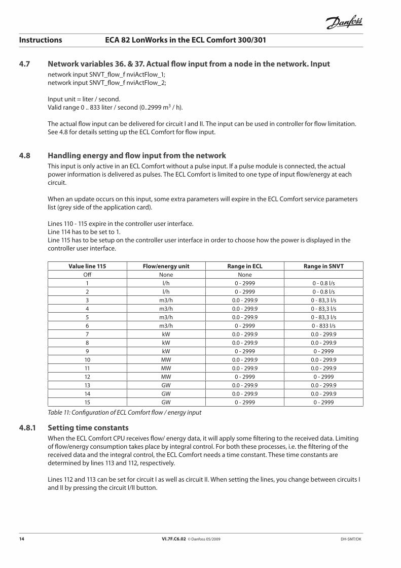
Lines 110 - 115 expire in the controller user interface.Line 114 has to be set to 1.Line 115 has to be setup on the controller user interface in order to choose how the power is displayed in the controller user interface.
Value line 115 Flow/energy unit Range in ECL Range in SNVTOff None None1 l/h 0 - 2999 0 - 0.8 l/s2 l/h 0 - 2999 0 - 0.8 l/s3 m3/h 0.0 - 299.9 0 - 83,3 l/s4 m3/h 0.0 - 299.9 0 - 83,3 l/s5 m3/h 0.0 - 299.9 0 - 83,3 l/s6 m3/h 0 - 2999 0 - 833 l/s7 kW 0.0 - 299.9 0.0 - 299.98 kW 0.0 - 299.9 0.0 - 299.99 kW 0 - 2999 0 - 2999
10 MW 0.0 - 299.9 0.0 - 299.911 MW 0.0 - 299.9 0.0 - 299.912 MW 0 - 2999 0 - 299913 GW 0.0 - 299.9 0.0 - 299.914 GW 0.0 - 299.9 0.0 - 299.915 GW 0 - 2999 0 - 2999
Table 11: Configuration of ECL Comfort flow / energy input
4.8.1 Setting time constantsWhen the ECL Comfort CPU receives flow/ energy data, it will apply some filtering to the received data. Limiting of flow/energy consumption takes place by integral control. For both these processes, i.e. the filtering of the received data and the integral control, the ECL Comfort needs a time constant. These time constants are determined by lines 113 and 112, respectively.
Lines 112 and 113 can be set for circuit I as well as circuit II. When setting the lines, you change between circuits I and II by pressing the circuit I/II button.
DH-SMT/DK VI.7F.C6.02 © Danfoss 05/2009 15
Instructions ECA 82 LonWorks in the ECL Comfort 300/301
Line Range Default value Description112 1 – 250 40 Line 112 is a time constant for integral control of flow/energy limiting. A high value of
112 means fast control, a low value means slow (more stable) control113 1 – 250 2 Line 113 is a time constant for digital filtering of flow/energy input data. When line 113
is set to 1, no filtering is applied. A high value of 113 means that a degree of filtering applied
Table 12: Adjustment of time constants
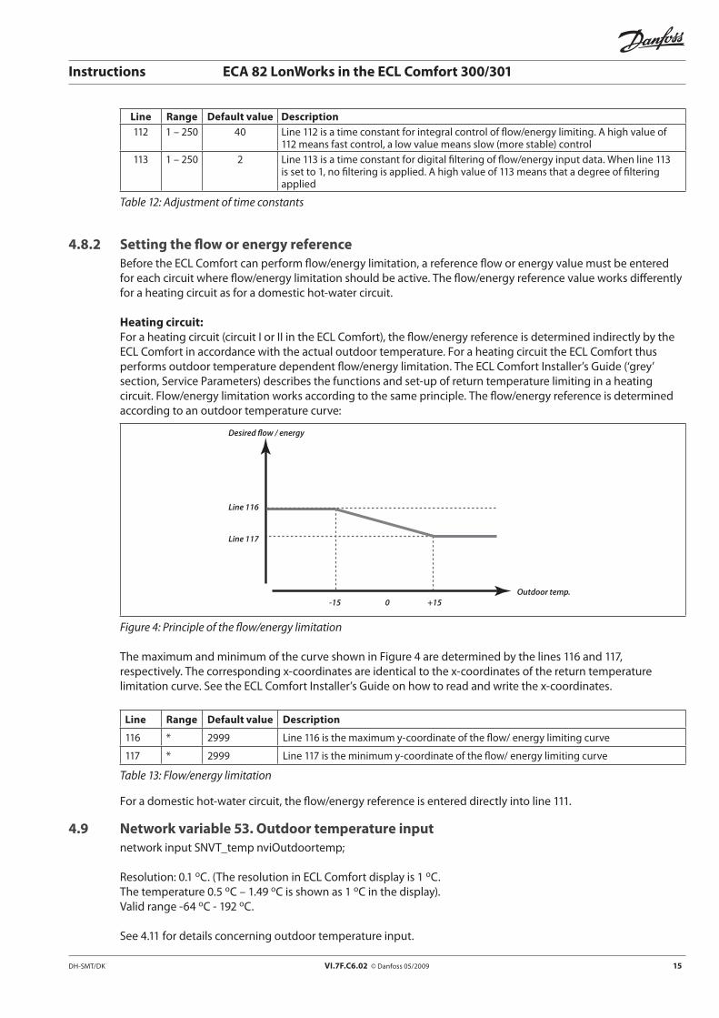
4.8.2 Setting the flow or energy referenceBefore the ECL Comfort can perform flow/energy limitation, a reference flow or energy value must be entered for each circuit where flow/energy limitation should be active. The flow/energy reference value works differently for a heating circuit as for a domestic hot-water circuit.
Heating circuit:For a heating circuit (circuit I or II in the ECL Comfort), the flow/energy reference is determined indirectly by the ECL Comfort in accordance with the actual outdoor temperature. For a heating circuit the ECL Comfort thus performs outdoor temperature dependent flow/energy limitation. The ECL Comfort Installer’s Guide (‘grey’ section, Service Parameters) describes the functions and set-up of return temperature limiting in a heating circuit. Flow/energy limitation works according to the same principle. The flow/energy reference is determined according to an outdoor temperature curve:
Desired flow / energy
Line 116
Line 117
Outdoor temp. -15 0 +15
Figure 4: Principle of the flow/energy limitation
The maximum and minimum of the curve shown in Figure 4 are determined by the lines 116 and 117, respectively. The corresponding x-coordinates are identical to the x-coordinates of the return temperature limitation curve. See the ECL Comfort Installer’s Guide on how to read and write the x-coordinates.
Line Range Default value Description
116 * 2999 Line 116 is the maximum y-coordinate of the flow/ energy limiting curve
117 * 2999 Line 117 is the minimum y-coordinate of the flow/ energy limiting curve
Table 13: Flow/energy limitation
For a domestic hot-water circuit, the flow/energy reference is entered directly into line 111.
4.9 Network variable 53. Outdoor temperature inputnetwork input SNVT_temp nviOutdoortemp;
Resolution: 0.1 oC. (The resolution in ECL Comfort display is 1 oC. The temperature 0.5 oC – 1.49 oC is shown as 1 oC in the display).Valid range -64 oC - 192 oC.
See 4.11 for details concerning outdoor temperature input.
16 VI.7F.C6.02 © Danfoss 05/2009 DH-SMT/DK
Instructions ECA 82 LonWorks in the ECL Comfort 300/301
4.10 Network variable 54. Outdoor temperature inputnetwork input SNVT_temp_p nviOutdoortemp_p;
Resolution: 0.01 oC. (The resolution in ECL Comfort display is 1 oC).Valid range -64 oC - 192 oC.
See 4.11 for details concerning outdoor temperature input.
4.11 General handling of outdoor temperature inputIn order to use this input for weather compensation in the ECL Comfort, no physical outdoor sensor can be connected. If a physical sensor is mounted, the outdoor temperature input will come from the ECL controller. The physical sensor always has the highest priority. The ECL Comfort must act as a slave (no outdoor sensor connected) in order to use outdoor sensor values from the network. This influences the possibility of combining the controller with other remote controllers: ECA 60, ECA 61 and ECA 63. The connection can be verified: Outdoor temperature is shown in the controller display at the user side, line A, bottom left.-64 oC indicates a short-circuited sensor. 192 oC indicates that no sensor mounted.
4.12 Network variables 6. 7. & 17.-20. & 46.–49. Temperature sensors 1-10: Outputnetwork output SNVT_temp nvoSensorNr_1 network output SNVT_temp nvoSensorNr_2;network output SNVT_temp nvoSensorNr_3;network output SNVT_temp nvoSensorNr_4;network output SNVT_temp nvoSensorNr_5;network output SNVT_temp nvoSensorNr_6;network output SNVT_temp nvoSensorNr_7;network output SNVT_temp nvoSensorNr_8;network output SNVT_temp nvoSensorNr_9;network output SNVT_temp nvoSensorNr_10;
Measured temperature values from the ECL Comfort sensors are sent to the network.
Valid rangeMeasured temperatures within the range -58 °C - 158 °C can be indicated. • 192oC indicates that no sensor has been installed.• -64oCindicates that the sensor has been short-circuited.
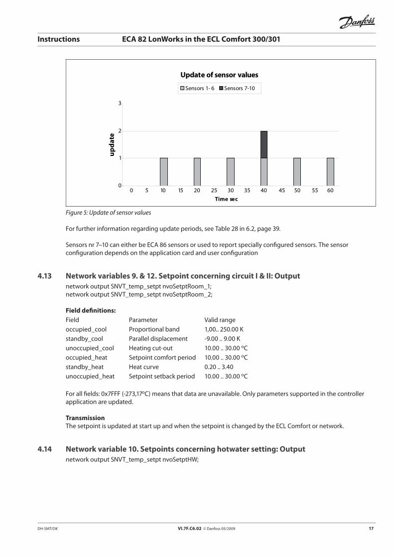
Updating speedThe built-in sensors (sensors 1-6) have an update period of 2 * SendHeartBeat.The ECA 86 sensors connected (sensors 7-10) have an update period of 8 * SendHeartBeat. The update sequence is illustrated in Figure 5 at a SendHeartBeat value = 5 sec.
DH-SMT/DK VI.7F.C6.02 © Danfoss 05/2009 17
Instructions ECA 82 LonWorks in the ECL Comfort 300/301
Update of sensor values
0
1
2
3
0 5 10 15 20 25 30 35 40 45 50 55 60Time sec
upda
te
Sensors 1- 6 Sensors 7-10
Figure 5: Update of sensor values
For further information regarding update periods, see Table 28 in 6.2, page 39.
Sensors nr 7–10 can either be ECA 86 sensors or used to report specially configured sensors. The sensor configuration depends on the application card and user configuration
4.13 Network variables 9. & 12. Setpoint concerning circuit I & II: Outputnetwork output SNVT_temp_setpt nvoSetptRoom_1;network output SNVT_temp_setpt nvoSetptRoom_2;
Field definitions:Field Parameter Valid range occupied_cool Proportional band 1,00.. 250.00 Kstandby_cool Parallel displacement -9.00 .. 9.00 K unoccupied_cool Heating cut-out 10.00 .. 30.00 oC occupied_heat Setpoint comfort period 10.00 .. 30.00 oC standby_heat Heat curve 0.20 .. 3.40 unoccupied_heat Setpoint setback period 10.00 .. 30.00 oC
For all fields: 0x7FFF (-273,17oC) means that data are unavailable. Only parameters supported in the controller application are updated.
TransmissionThe setpoint is updated at start up and when the setpoint is changed by the ECL Comfort or network.
4.14 Network variable 10. Setpoints concerning hotwater setting: Outputnetwork output SNVT_temp_setpt nvoSetptHW;

18 VI.7F.C6.02 © Danfoss 05/2009 DH-SMT/DK
Instructions ECA 82 LonWorks in the ECL Comfort 300/301
Field Parameter occupied_cool Hot water temp. difference standby_cool Charging temp. - relative unoccupied_cool Difference 1 - cut-out temp. occupied_heat Setpoint comfort period standby_heat Difference 2 - cut-in temp. unoccupied_heat Setpoint setback period
The proportional band of the hot water is reported in network input SNVT_temp_setpt nvoTSetptRoom_2, occupied_cool.
For all fields: 0x7FFF (-273,17 oC) means that data are unavailable. Only parameters supported in the controller application are updated.
TransmissionThe SNVT is updated at start-up and if the variable is changed by the ECL Comfort or network.
4.15 Network variables 13. & 14. & 61. Status of valves, optimizer status and relative humidity
network output SNVT_setting nvoValve_1;network output SNVT_setting nvoValve_2;network output SNVT_setting nvoValve_3;
Setting_t (not applicable for nvoValve_3):The valve control signals from the controller are reported. The valve status is based on the triac output.
2 SET DOWN => valve down 3 SET UP => valve up 4 SET STOP => stop valve
The controller mode fields are not included in this SNVT output. See 4.19, page 27 for reporting mode output.
Rotation:The optimizer status is listed in the code shown in Table 14. The optimizer status can be read in controller display on the user’s side, line A, B or C to the right in the display. If the controller is running in automatic mode, an additional arrow appears at the left side of the sun or moon symbol, indicating the optimizer/controller status.
Rotation value Optimizer status Display in ECL Comfort
10.00 Setback (night) Moon
25.00 Cooling, shifting from comfort to setback Blinking moon (optimizer)
50.00 Heating, shifting from setback to comfort Blinking sun (optimizer)
100.00 Comfort (day) Sun
Table 14: Optimizer status
Update rateThe update period is set in ECL checks for adjustments see 5.3.10.4 or Table 22, page 32.
DH-SMT/DK VI.7F.C6.02 © Danfoss 05/2009 19
Instructions ECA 82 LonWorks in the ECL Comfort 300/301
4.16 Network variable 22. Reading off time and date: Outputnetwork output SNVT_time_stamp nvoTime;
The actual time and date set in the ECL Comfort can be read here.
Field:Year 1996 - 2026Month 1-12Day 1-31Hour 0-23Minute 0-59Second Not supported.
Update rateThe time is updated at SendHeartBeat * 8.
4.17 Network variable 33. Pump status network output SNVT_state nvoControl;
The pump setting (relay positions) in the ECL Comfort controller can be read.
For all bits: 1 = relay in, no connection. Pump is stopped.0 = relay out, connection. Pump is running.
Bit 0: Standard relay 1 Bit 1: Standard relay 2Bit 2: Standard relay 3Bit 3: Relay 1 in ECA 80 or ECA 86Bit 4: Relay 2 in ECA 80 or ECA 86
Update rateThe update frequency is set in ECL checks for adjustments, see 5.3.10.4 or Table 22.
4.18 Network variable 56. Reporting week plan in ECL Comfort. Outputnetwork output SNVT_str_asc nvoWeekplan;
The request from nviWeekplan is reported here.Decoding of the week plan report can be read in Table 9 and Table 10.
Error codes:If a non-valid request has been made from nviWeekplan, error messages will be displayed here directly as ASCII character.
“Error.Nocircuitchosen!”accii[30] Contains the wrong or missing circuit information copied from nviWeekPlan.
“Too many periods reduce day: “accii[29] Contains the day number with too many periods.ascii[30] contains information copied from nviWeekPlan.
20 VI.7F.C6.02 © Danfoss 05/2009 DH-SMT/DK
Instructions ECA 82 LonWorks in the ECL Comfort 300/301
A maximum of 3 continuously periods a day can be set.
TransmissionOnly transmitted after a request from nviWeekplan.
4.19 Network variables 57. & 58. & 60. Controller mode status, circuit I & II & III. Outputnetwork output SNVT_hvac_mode nvoMode_1;network output SNVT_hvac_mode nvoMode_2;network output SNVT_hvac_mode nvoMode_3;
Here the actual controller mode in circuit I and II can be read.0 HVAC_AUTO Automatic mode (clock)1 HVAC_HEAT Permanent comfort (sun)4 HVAC_NIGHT_PURGE Permanent setback (moon)6 HVAC_OFF Standby mode (Off symbol)7 HVAC_TEST Manuel mode (Hand)0xFF HVAC_NUL Value not available
Update rateThe update frequency is set in ECL checks for adjustments see 5.3.10.4 or Table 22, page 32.
4.20 Network variables 42. & 43. Actual power delivered from pulse module. Outputnetwork output SNVT_power_f nvoActPower_1;network output SNVT_power_f nvoActPower_2;
If a pulse module is connected, the actual energy information is reported here.-1.0E38 indicates no data.
Only one type of information, i.e. flow or energy can be reported in each controller circuit. See the supplementary instruction for ECL Comfort 300 with pulse module set-up of pulse information in ECL Comfort.
Update rateThe update period is 8 * SendheartBeat. See Table 28, page 39, for further details.
4.21 Network variables 44. & 45. Actual flow delivered from pulse module. Outputnetwork output SNVT_flow_f nvoActFlow_1;network output SNVT_flow_f nvoActFlow_2;
If an ECA 88 is connected the actual flow information’s is reported here.-1.0E38 indicates no data.
Only one type of information, i.e. flow or energy can be reported in each controller circuit. See the supplementary instruction for ECL Comfort 300 with pulse module set-up of pulse information in ECL Comfort.
Update rateThe update period is 8 * SendHeartBeat. See Table 28, page 39, for further details.
DH-SMT/DK VI.7F.C6.02 © Danfoss 05/2009 21
Instructions ECA 82 LonWorks in the ECL Comfort 300/301
4.22 Network variables 27. – 30. Sensor references 3-6. Outputnetwork output SNVT_temp nvoRef_Nr_3;network output SNVT_temp nvoRef_Nr_4;network output SNVT_temp nvoRef_Nr_5;network output SNVT_temp nvoRef_Nr_6;
The physical sensors can have a calculated reference value depending on measured temperatures and setting in the controller. If a sensor has a reference, the value is displayed here. The reference value can be seen in the display by pressing the toggle switch in the picture, where the sensor value is shown.
Update rateThe update period is 4 * SendHeartBeat. See Table 28, page 39, for further details.
22 VI.7F.C6.02 © Danfoss 05/2009 DH-SMT/DK
Instructions ECA 82 LonWorks in the ECL Comfort 300/301
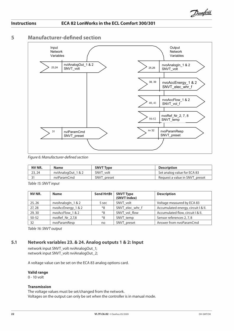
5 Manufacturer-defined section
Input Network Variables
Output Network Variables
25,26
nvoAnalogIn_1 & 2 SNVT_volt
23,24
nviAnalogOut_1 & 2 SNVT_volt
50-52
nvoRef_Nr_2, 7, 8 SNVT_temp
31 nviParamCmd SNVT_preset
nv 32 nvoParamResp SNVT_preset
40, 41
nvoAccFlow_1 & 2 SNVT_vol_f
38, 39 nvoAccEnergy_1 & 2 SNVT_elec_whr_f
Figure 6: Manufacturer-defined section
NV NR. Name SNVT Type Description 23, 24 nviAnalogOut_1 & 2 SNVT_volt Set analog value for ECA 8331 nviParamCmd SNVT_preset Request a value in SNVT_preset
Table 15: SNVT input
NV NR. Name Send HrtBt SNVT Type(SNVT Index)
Description
25, 26 nvoAnalogIn_1 & 2 5 sec SNVT_volt Voltage measured by ECA 8327, 28 nvoAccEnergy_1 & 2 *8 SNVT_elec_whr_f Accumulated energy, circuit I & II.29, 30 nvoAccFlow_1 & 2 *8 SNVT_vol_flow Accumulated flow, circuit I & II.50-52 nvoRef_Nr_2,7,8 *8 SNVT_temp Sensor references 2, 7, 832 nvoParamResp no SNVT_preset Answer from nvoParamCmd
Table 16: SNVT output
5.1 Network variables 23. & 24. Analog outputs 1 & 2: Inputnetwork input SNVT_volt nviAnalogOut_1;network input SNVT_volt nviAnalogOut_2;
A voltage value can be set on the ECA 83 analog options card.
Valid range0 - 10 volt
TransmissionThe voltage values must be set/changed from the network.Voltages on the output can only be set when the controller is in manual mode.

DH-SMT/DK VI.7F.C6.02 © Danfoss 05/2009 23
Instructions ECA 82 LonWorks in the ECL Comfort 300/301
5.2 Network variables 25. & 26. Analog inputs 1 & 2: Outputnetwork output SNVT_volt nvoAnalogIn_1;network output SNVT_volt nvoAnalogIn_2;
Values measured on the ECA 83 are transmitted from here out to the network.
Valid range0 - 10 volt
UpdatingThe update frequency is set in Voltage update, see 5.3.10.3, page 32, or Table 28.
Inactive valueIf the variable is not used in the application, the value is set to 0.0 volt.
5.3 Network variables 19. & 20. Parameter command and responsenetwork input SNVT_preset nviParamCmd;network output SNVT_preset nvoParamResp;
The optimization parameters in ECL Comfort can be read and written by these.It is only possible to read parameters that are active in the ECL Comfort application. Parameters, which concern the hardware configuration, are not supported in the ECA 82.
Error messages are displayed as a consequence of the following:Max and min values depend on the application in ECL Comfort and will be tested against the max and min values given in the application.
The following functions are used in SNVT_preset:• nviParamCmd.learn:min=0,max=3,see5.3.1.• nviParamCmd.selector:min=1,max=1051,see5.3.2.• nviParamCmd.value[0]:errormessage,see5.3.3Valuefield.• nviParamCmd.value[1]:notused• nviParamCmd.value[2]:highbyteofcommunicationparameter/variable• nviParamCmd.value[3]:lowbyteofcommunicationparameter/variable• nviParamCmd.day:notsupported• nviParamCmd.hour:notsupported• nviParamCmd.minute:notsupported• nviParamCmd.second:notsupported• nviParamCmd.millisecond:notsupported
The 8 least significant bits are placed in nviParamCmd.value [3] and the 8 most significant bits in nviParamCmd.value [2]. 16-bit values must always be used for 1, 4, 8 and 16-bit values, but it is only with negative values that this is valid since the most significant bit is 0 for positive values.
5.3.1 Learn fieldThe learn field can contain 4 values:LN_RECALL(0) read commandLN_LEARN_CURRENT(1) write commandLN_REPORT_VALUE(2) read commandLN_REPORT_VALUE(3) write command
The function in LN_RECALL and LN_REPORT_VALUE is identical, just as LN_LEARN_CURRENT and LN_REPORT_VALUE are identical.
24 VI.7F.C6.02 © Danfoss 05/2009 DH-SMT/DK
Instructions ECA 82 LonWorks in the ECL Comfort 300/301
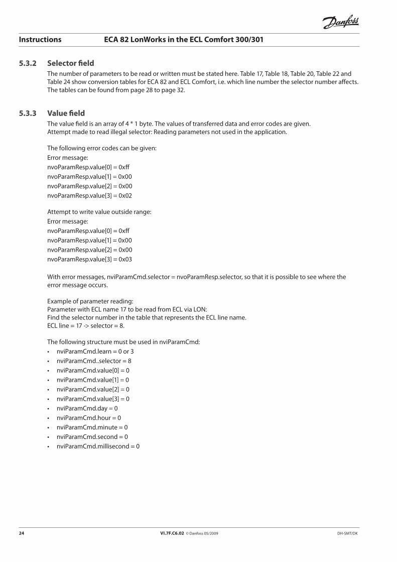
5.3.2 Selector fieldThe number of parameters to be read or written must be stated here. Table 17, Table 18, Table 20, Table 22 and Table 24 show conversion tables for ECA 82 and ECL Comfort, i.e. which line number the selector number affects. The tables can be found from page 28 to page 32.
5.3.3 Value fieldThe value field is an array of 4 * 1 byte. The values of transferred data and error codes are given. Attempt made to read illegal selector: Reading parameters not used in the application.
The following error codes can be given:Error message:nvoParamResp.value[0] = 0xffnvoParamResp.value[1] = 0x00nvoParamResp.value[2] = 0x00nvoParamResp.value[3] = 0x02
Attempt to write value outside range:Error message:nvoParamResp.value[0] = 0xffnvoParamResp.value[1] = 0x00nvoParamResp.value[2] = 0x00nvoParamResp.value[3] = 0x03
With error messages, nviParamCmd.selector = nvoParamResp.selector, so that it is possible to see where the error message occurs.
Example of parameter reading:Parameter with ECL name 17 to be read from ECL via LON:Find the selector number in the table that represents the ECL line name.ECL line = 17 -> selector = 8.
The following structure must be used in nviParamCmd:• nviParamCmd.learn=0or3• nviParamCmd..selector=8• nviParamCmd.value[0]=0• nviParamCmd.value[1]=0• nviParamCmd.value[2]=0• nviParamCmd.value[3]=0• nviParamCmd.day=0• nviParamCmd.hour=0• nviParamCmd.minute=0• nviParamCmd.second=0• nviParamCmd.millisecond=0
DH-SMT/DK VI.7F.C6.02 © Danfoss 05/2009 25
Instructions ECA 82 LonWorks in the ECL Comfort 300/301
The answer can now be read in nvoParamResp, as the following pattern:• nvoParamResp.learn=0or3,thesameasinnviParamCmd.learn.• nvoParamCmd..selector=8,thesameasinnviParamCmd.selector.• nvoParamCmd.value[0]=0ifthereadingisOK,255forerror.• nvoParamCmd.value[1]=0• nvoParamCmd.value[2]=Highbyteofreadvalue.• nvoParamCmd.value[3]=Lowbyteofreadvalue,orpossibleerrorcode.• nvoParamCmd.day=0• nvoParamCmd.hour=0• nvoParamCmd.minute=0• nvoParamCmd.second=0• nvoParamCmd.millisecond=0
Example of writing a value for ECL Comfort:The following structure must be used in ParamCmd:• nviParamCmd.learn=1or2• nviParamCmd..selector=8• nviParamCmd.value[0]=0• nviParamCmd.value[1]=0• nviParamCmd.value[2]=Highbyteofvaluetobewritten.• nviParamCmd.value[3]=Lowbyteofvaluetobewritten.• nviParamCmd.day=0• nviParamCmd.hour=0• nviParamCmd.minute=0• nviParamCmd.second=0• nviParamCmd.millisecond=0
The answer can now be read in nvoParamResp according to the followingpattern:• nviParamResp.learn=1or2,thesameasinnviParamCmd.learn.• nviParamCmd..selector=8,thesameasinnviParamCmd.selector.• nviParamCmd.value[0]=0forOK,255forerror.• nviParamCmd.value[1]=0• nviParamCmd.value[2]=ConfirmationofwrittenHighbytevalue.• nviParamCmd.value[3]=ConfirmationofwrittenLowbytevalueorpossibleerrorcode.• nviParamCmd.day=0• nviParamCmd.hour=0• nviParamCmd.minute=0• nviParamCmd.second=0• nviParamCmd.millisecond=0
The table on the next page shows all possibilities in SNVT_preset. No max and min values are given since these are application-dependent. A test is performed on the ECL after every written entry to see whether or not the value is within the permissible range.
26 VI.7F.C6.02 © Danfoss 05/2009 DH-SMT/DK
Instructions ECA 82 LonWorks in the ECL Comfort 300/301
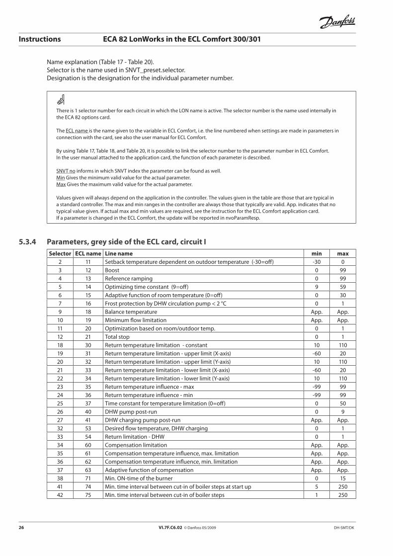
Name explanation (Table 17 - Table 20).Selector is the name used in SNVT_preset.selector.Designation is the designation for the individual parameter number.
There is 1 selector number for each circuit in which the LON name is active. The selector number is the name used internally in the ECA 82 options card.
The ECL name is the name given to the variable in ECL Comfort, i.e. the line numbered when settings are made in parameters in connection with the card, see also the user manual for ECL Comfort.
By using Table 17, Table 18, and Table 20, it is possible to link the selector number to the parameter number in ECL Comfort.In the user manual attached to the application card, the function of each parameter is described.
SNVT no informs in which SNVT index the parameter can be found as well.Min Gives the minimum valid value for the actual parameter.Max Gives the maximum valid value for the actual parameter.
Values given will always depend on the application in the controller. The values given in the table are those that are typical in a standard controller. The max and min ranges in the controller are always those that typically are valid. App. indicates that no typical value given. If actual max and min values are required, see the instruction for the ECL Comfort application card.If a parameter is changed in the ECL Comfort, the update will be reported in nvoParamResp.
5.3.4 Parameters, grey side of the ECL card, circuit ISelector ECL name Line name min max
2 11 Setback temperature dependent on outdoor temperature (-30=off) -30 03 12 Boost 0 994 13 Reference ramping 0 995 14 Optimizing time constant (9=off) 9 596 15 Adaptive function of room temperature (0=off) 0 307 16 Frost protection by DHW circulation pump < 2 °C 0 19 18 Balance temperature App. App.
10 19 Minimum flow limitation App. App.11 20 Optimization based on room/outdoor temp. 0 112 21 Total stop 0 118 30 Return temperature limitation - constant 10 11019 31 Return temperature limitation - upper limit (X-axis) -60 2020 32 Return temperature limitation - upper limit (Y-axis) 10 11021 33 Return temperature limitation - lower limit (X-axis) -60 2022 34 Return temperature limitation - lower limit (Y-axis) 10 11023 35 Return temperature influence - max -99 9924 36 Return temperature influence - min -99 9925 37 Time constant for temperature limitation (0=off) 0 5026 40 DHW pump post-run 0 927 41 DHW charging pump post-run App. App.32 53 Desired flow temperature, DHW charging 0 133 54 Return limitation - DHW 0 134 60 Compensation limitation App. App.35 61 Compensation temperature influence, max. limitation App. App.36 62 Compensation temperature influence, min. limitation App. App.37 63 Adaptive function of compensation App. App.38 71 Min. ON-time of the burner 0 1541 74 Min. time interval between cut-in of boiler steps at start up 5 25042 75 Min. time interval between cut-in of boiler steps 1 250

DH-SMT/DK VI.7F.C6.02 © Danfoss 05/2009 27
Instructions ECA 82 LonWorks in the ECL Comfort 300/301
Selector ECL name Line name min max43 76 Number of boiler steps (η) 1 845 78 Setpoint, miscellaneous App. App.46 79 Difference, miscellaneous App. App.47 80 Time set-up, miscellaneous App. App.48 81 Time constant (temperature filter) I App. App.49 82 Time constant (temperature filter) II App. App.52 85 Application selection I, miscellaneous App. App.53 86 Delayed cut-in I App. App.54 87 Delayed cut-in II App. App.55 88 R1 function App. App.56 89 R2 function App. App.57 90 R3 function App. App.58 91 Period time step I App. App.59 92 Period time step II App. App.60 55 DHW circulation during DHW charging 0 161 56 Compensation limit App. App.62 57 Compensation influence - min App. App.63 58 Compensation App. App.64 59 Adaptive function of compensation App. App.65 98 Wind speed m/s App. App.66 99 Set valve position manual (0-250) App. App.67 100 Accumulated outdoor temperature -64 19268 101 Accumulated room temperature -64 19269 102 Actual humidity 0 10070 103 Dew point temperature App. App.71 104 Valve position 0-100% 0 10072 105 Reserved73 106 Reserved74 107 Reserved75 108 Reserved76 109 Reserved78 111 Actual setpoint flow/energy 0 299979 112 Tau flow integrator 1 25080 113 Tau flow filter integrator 1 25082 115 Flow unit 0 1583 116 Flow limiter - upper value (y coordinate) 0 299984 117 Flow limiter - lower value (y coordinate) 0 299985 118 Reserved86 119 Reserved87 120 Reserved88 121 Reserved89 122 Reserved90 163 Cooling, activation difference, actual room temperature App. App.91 164 Displacement of the calculated dew point temperature App. App.94 142 Alarm type (on/off) App. App.95 143 Alarm setpoint 1 App. App.96 144 Alarm setpoint 2 App. App.97 145 Alarm setpoint 3 App. App.98 146 Alarm setpoint 4 App. App.
101 152 Maximum tank temperature App. App.102 153 Delay time - change from heating to DHW App. App.
28 VI.7F.C6.02 © Danfoss 05/2009 DH-SMT/DK
Instructions ECA 82 LonWorks in the ECL Comfort 300/301
Selector ECL name Line name min max103 154 Start difference - DHW App. App.104 155 Stop difference - DHW App. App.105 160 Max outdoor temp (stop limit) App. App.106 161 Min outdoor temp (stop limit) App. App.107 162 General set point App. App.108 165 Reserved109 166 Maximum difference - step I App. App.110 167 Minimum temperature - step II valve opening App. App.111 168 Cut-in delay of boiler App. App.112 169 Difference step II App. App.113 170 Heat pump stop at high return temperature App. App.125 188 BEM-function App. App.132 198 Daylight saving time changeover 0 1
Table 17: Circuit I, service parameters
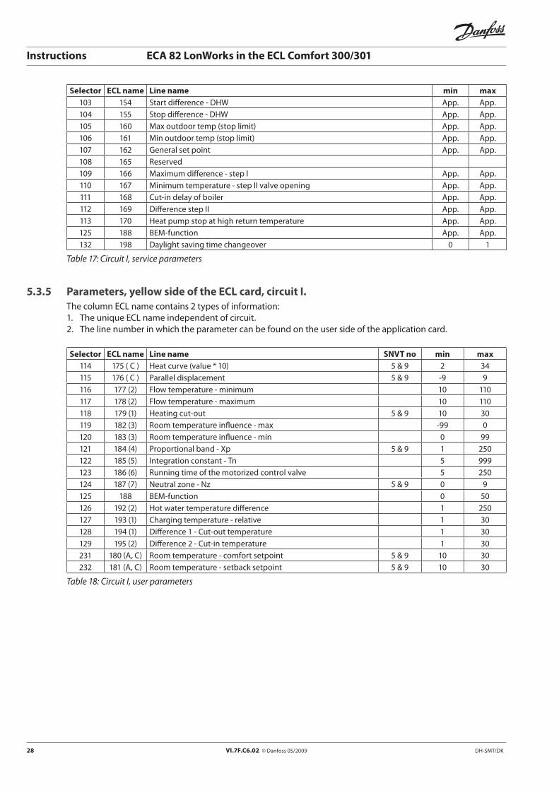
5.3.5 Parameters, yellow side of the ECL card, circuit I.The column ECL name contains 2 types of information: 1. The unique ECL name independent of circuit.2. The line number in which the parameter can be found on the user side of the application card.
Selector ECL name Line name SNVT no min max114 175 ( C ) Heat curve (value * 10) 5 & 9 2 34115 176 ( C ) Parallel displacement 5 & 9 -9 9116 177 (2) Flow temperature - minimum 10 110117 178 (2) Flow temperature - maximum 10 110118 179 (1) Heating cut-out 5 & 9 10 30119 182 (3) Room temperature influence - max -99 0120 183 (3) Room temperature influence - min 0 99121 184 (4) Proportional band - Xp 5 & 9 1 250122 185 (5) Integration constant - Tn 5 999123 186 (6) Running time of the motorized control valve 5 250124 187 (7) Neutral zone - Nz 5 & 9 0 9125 188 BEM-function 0 50126 192 (2) Hot water temperature difference 1 250127 193 (1) Charging temperature - relative 1 30128 194 (1) Difference 1 - Cut-out temperature 1 30129 195 (2) Difference 2 - Cut-in temperature 1 30231 180 (A, C) Room temperature - comfort setpoint 5 & 9 10 30232 181 (A, C) Room temperature - setback setpoint 5 & 9 10 30
Table 18: Circuit I, user parameters
DH-SMT/DK VI.7F.C6.02 © Danfoss 05/2009 29
Instructions ECA 82 LonWorks in the ECL Comfort 300/301
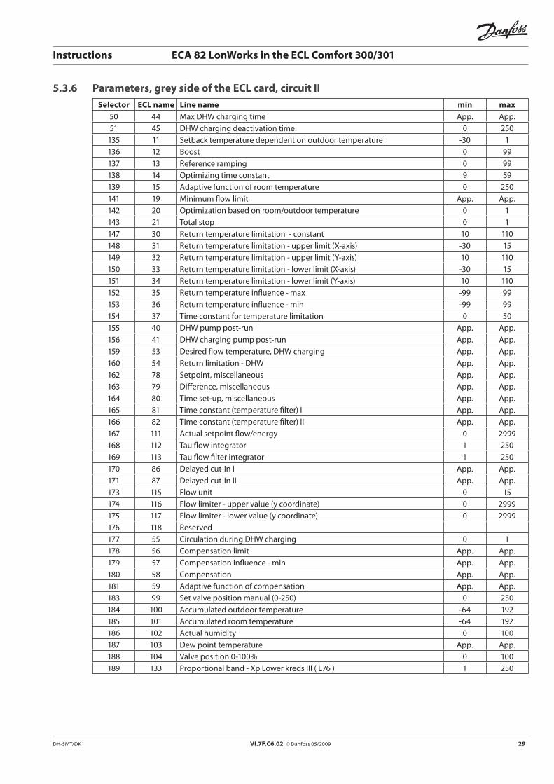
5.3.6 Parameters, grey side of the ECL card, circuit IISelector ECL name Line name min max
50 44 Max DHW charging time App. App.51 45 DHW charging deactivation time 0 250
135 11 Setback temperature dependent on outdoor temperature -30 1136 12 Boost 0 99137 13 Reference ramping 0 99138 14 Optimizing time constant 9 59139 15 Adaptive function of room temperature 0 250141 19 Minimum flow limit App. App.142 20 Optimization based on room/outdoor temperature 0 1143 21 Total stop 0 1147 30 Return temperature limitation - constant 10 110148 31 Return temperature limitation - upper limit (X-axis) -30 15149 32 Return temperature limitation - upper limit (Y-axis) 10 110150 33 Return temperature limitation - lower limit (X-axis) -30 15151 34 Return temperature limitation - lower limit (Y-axis) 10 110152 35 Return temperature influence - max -99 99153 36 Return temperature influence - min -99 99154 37 Time constant for temperature limitation 0 50155 40 DHW pump post-run App. App.156 41 DHW charging pump post-run App. App.159 53 Desired flow temperature, DHW charging App. App.160 54 Return limitation - DHW App. App.162 78 Setpoint, miscellaneous App. App.163 79 Difference, miscellaneous App. App.164 80 Time set-up, miscellaneous App. App.165 81 Time constant (temperature filter) I App. App.166 82 Time constant (temperature filter) II App. App.167 111 Actual setpoint flow/energy 0 2999168 112 Tau flow integrator 1 250169 113 Tau flow filter integrator 1 250170 86 Delayed cut-in I App. App.171 87 Delayed cut-in II App. App.173 115 Flow unit 0 15174 116 Flow limiter - upper value (y coordinate) 0 2999175 117 Flow limiter - lower value (y coordinate) 0 2999176 118 Reserved177 55 Circulation during DHW charging 0 1178 56 Compensation limit App. App.179 57 Compensation influence - min App. App.180 58 Compensation App. App.181 59 Adaptive function of compensation App. App.183 99 Set valve position manual (0-250) 0 250184 100 Accumulated outdoor temperature -64 192185 101 Accumulated room temperature -64 192186 102 Actual humidity 0 100187 103 Dew point temperature App. App.188 104 Valve position 0-100% 0 100189 133 Proportional band - Xp Lower kreds III ( L76 ) 1 250
30 VI.7F.C6.02 © Danfoss 05/2009 DH-SMT/DK
Instructions ECA 82 LonWorks in the ECL Comfort 300/301
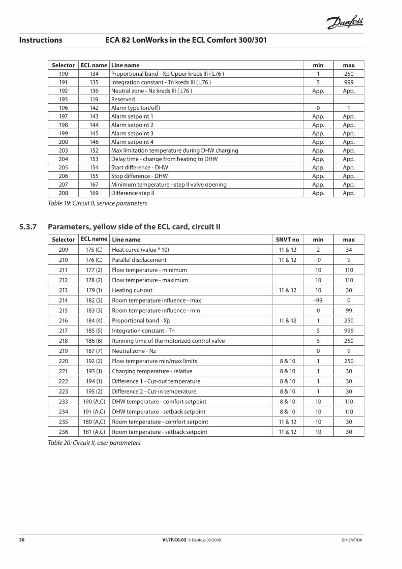
Selector ECL name Line name min max190 134 Proportional band - Xp Upper kreds III ( L76 ) 1 250191 135 Integration constant - Tn kreds III ( L76 ) 5 999192 136 Neutral zone - Nz kreds III ( L76 ) App. App.193 119 Reserved196 142 Alarm type (on/off) 0 1197 143 Alarm setpoint 1 App. App.198 144 Alarm setpoint 2 App. App.199 145 Alarm setpoint 3 App. App.200 146 Alarm setpoint 4 App. App.203 152 Max limitation temperature during DHW charging App. App.204 153 Delay time - change from heating to DHW App. App.205 154 Start difference - DHW App. App.206 155 Stop difference - DHW App. App.207 167 Minimum temperature - step II valve opening App. App.208 169 Difference step II App. App.
Table 19: Circuit II, service parameters
5.3.7 Parameters, yellow side of the ECL card, circuit II
Selector ECL name Line name SNVT no min max
209 175 (C) Heat curve (value * 10) 11 & 12 2 34
210 176 (C) Parallel displacement 11 & 12 -9 9
211 177 (2) Flow temperature - minimum 10 110
212 178 (2) Flow temperature - maximum 10 110
213 179 (1) Heating cut-out 11 & 12 10 30
214 182 (3) Room temperature influence - max -99 0
215 183 (3) Room temperature influence - min 0 99
216 184 (4) Proportional band - Xp 11 & 12 1 250
217 185 (5) Integration constant - Tn 5 999
218 186 (6) Running time of the motorized control valve 5 250
219 187 (7) Neutral zone - Nz 0 9
220 192 (2) Flow temperature min/max limits 8 & 10 1 250
221 193 (1) Charging temperature - relative 8 & 10 1 30
222 194 (1) Difference 1 - Cut-out temperature 8 & 10 1 30
223 195 (2) Difference 2 - Cut-in temperature 8 & 10 1 30
233 190 (A,C) DHW temperature - comfort setpoint 8 & 10 10 110
234 191 (A,C) DHW temperature - setback setpoint 8 & 10 10 110
235 180 (A,C) Room temperature - comfort setpoint 11 & 12 10 30
236 181 (A,C) Room temperature - setback setpoint 11 & 12 10 30
Table 20: Circuit II, user parameters
DH-SMT/DK VI.7F.C6.02 © Danfoss 05/2009 31
Instructions ECA 82 LonWorks in the ECL Comfort 300/301
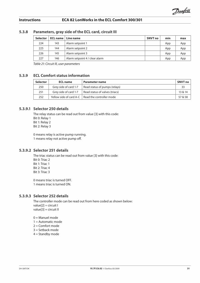
5.3.8 Parameters, gray side of the ECL card, circuit III
Selector ECL name Line name SNVT no min max
224 143 Alarm setpoint 1 App App
225 144 Alarm setpoint 2 App App
226 145 Alarm setpoint 3 App App
227 146 Alarm setpoint 4 / clear alarm App App
Table 21: Circuit III, user parameters
5.3.9 ECL Comfort status information
Selector ECL name Parameter name SNVT no
250 Grey side of card 1-7 Read status of pumps (relays) 33
251 Grey side of card 1-7 Read status of valves (triacs) 13 & 14
252 Yellow side of card A-C Read the controller mode 57 & 58
5.3.9.1 Selector 250 detailsThe relay status can be read out from value [3] with this code:Bit 0: Relay 1Bit 1: Relay 2Bit 2: Relay 3
0 means relay is active pump running.1 means relay not active pump off.
5.3.9.2 Selector 251 detailsThe triac status can be read out from value [3] with this code:Bit 0: Triac 2Bit 1: Triac 1Bit 2: Triac 4Bit 3: Triac 3
0 means triac is turned OFF.1 means triac is turned ON.
5.3.9.3 Selector 252 detailsThe controller mode can be read out from here coded as shown below:value[2] = circuit I value[3] = circuit II
0 = Manuel mode 1 = Automatic mode 2 = Comfort mode 3 = Setback mode 4 = Standby mode
32 VI.7F.C6.02 © Danfoss 05/2009 DH-SMT/DK
Instructions ECA 82 LonWorks in the ECL Comfort 300/301
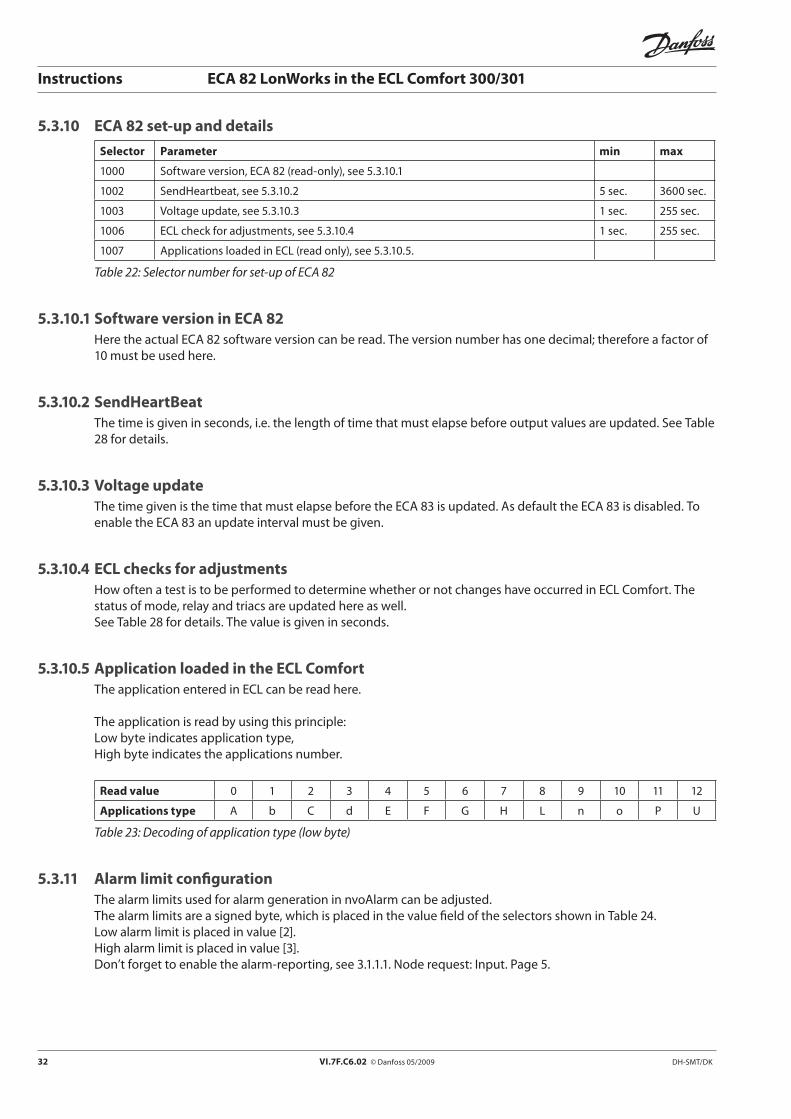
5.3.10 ECA 82 set-up and details
Selector Parameter min max
1000 Software version, ECA 82 (read-only), see 5.3.10.1
1002 SendHeartbeat, see 5.3.10.2 5 sec. 3600 sec.
1003 Voltage update, see 5.3.10.3 1 sec. 255 sec.
1006 ECL check for adjustments, see 5.3.10.4 1 sec. 255 sec.
1007 Applications loaded in ECL (read only), see 5.3.10.5.
Table 22: Selector number for set-up of ECA 82
5.3.10.1 Software version in ECA 82Here the actual ECA 82 software version can be read. The version number has one decimal; therefore a factor of 10 must be used here.
5.3.10.2 SendHeartBeatThe time is given in seconds, i.e. the length of time that must elapse before output values are updated. See Table 28 for details.
5.3.10.3 Voltage updateThe time given is the time that must elapse before the ECA 83 is updated. As default the ECA 83 is disabled. To enable the ECA 83 an update interval must be given.
5.3.10.4 ECL checks for adjustmentsHow often a test is to be performed to determine whether or not changes have occurred in ECL Comfort. The status of mode, relay and triacs are updated here as well. See Table 28 for details. The value is given in seconds.
5.3.10.5 Application loaded in the ECL ComfortThe application entered in ECL can be read here.
The application is read by using this principle:Low byte indicates application type,High byte indicates the applications number.
Read value 0 1 2 3 4 5 6 7 8 9 10 11 12
Applications type A b C d E F G H L n o P U
Table 23: Decoding of application type (low byte)
5.3.11 Alarm limit configurationThe alarm limits used for alarm generation in nvoAlarm can be adjusted.The alarm limits are a signed byte, which is placed in the value field of the selectors shown in Table 24.Low alarm limit is placed in value [2].High alarm limit is placed in value [3].Don’t forget to enable the alarm-reporting, see 3.1.1.1. Node request: Input. Page 5.

DH-SMT/DK VI.7F.C6.02 © Danfoss 05/2009 33
Instructions ECA 82 LonWorks in the ECL Comfort 300/301
Selector Alarm configuration Min Max
1018 Sensor 1 alarm limits -60 oC 126 oC
1019 Sensor 2 alarm limits -60 oC 126 oC
1020 Sensor 3 alarm limits -60 oC 126 oC
1021 Sensor 4 alarm limits -60 oC 126 oC
1022 Sensor 5 alarm limits -60 oC 126 oC
1023 Sensor 6 alarm limits -60 oC 126 oC
1024 Sensor 7 alarm limits -60 oC 126 oC
1025 Sensor 8 alarm limits -60 oC 126 oC
1026 Sensor 9 alarm limits -60 oC 126 oC
1027 Sensor 10 alarm limits -60 oC 126 oC
1028 Sensor 2 - reference 2 alarm limit -60 oCC 126 oC
1029 Sensor 3 - reference 3 alarm limit -60 oC 126 oC
1030 Sensor 4 - reference 4 alarm limit -60 oC 126 oC
1031 Sensor 5 - reference 5 alarm limit -60 oCC 126 oC
1032 Sensor 6 - reference 6 alarm limit -60 oC 126 oC
1033 Sensor 7 - reference 7 alarm limit -60 oC 126 oC
1034 Sensor 8 - reference 8 alarm limit -60 oC 126 oC
1035 Relative humidity 1 alarm limit 0% 100%
1036 Relative humidity 2 alarm limit 0% 100%
Table 24: Selectors for alarm limit configuration
5.3.12 Alarm code readoutThe alarm code set by the ECL Comfort application can be read here. This function is only running if the application in ECL Comfort generates an alarm.
The alarm function is supported by ECL Comfort 300 version 1.08. The alarm function requires alarm support in the application card.Bit value 1 means alarm on.Bit value 0 means alarm off.
Selector Alarm code
1048 Alarm code part 1 read out
1049 Alarm code part 2 read out
Table 25: Alarm bit in ECL Comfort
5.3.13 Accumulated energy or flow preloadThe start values for flow or energy can be set here. Typically, the value which is already accumulated in the heat meter can be preloaded. Use the unit configured in line 115, see Table 11, page 14.
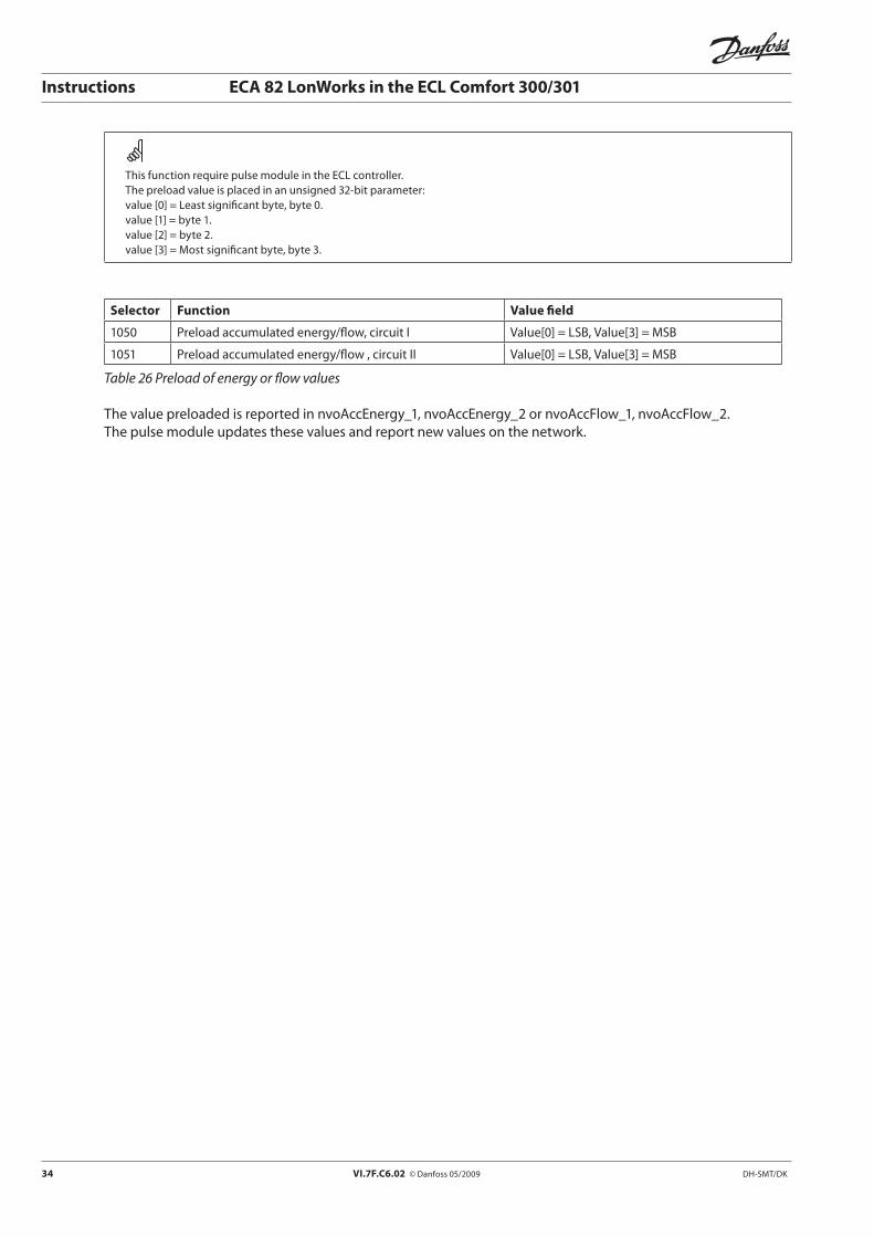
34 VI.7F.C6.02 © Danfoss 05/2009 DH-SMT/DK
Instructions ECA 82 LonWorks in the ECL Comfort 300/301
This function require pulse module in the ECL controller.The preload value is placed in an unsigned 32-bit parameter:value [0] = Least significant byte, byte 0.value [1] = byte 1.value [2] = byte 2.value [3] = Most significant byte, byte 3.
Selector Function Value field
1050 Preload accumulated energy/flow, circuit I Value[0] = LSB, Value[3] = MSB
1051 Preload accumulated energy/flow , circuit II Value[0] = LSB, Value[3] = MSB
Table 26 Preload of energy or flow values
The value preloaded is reported in nvoAccEnergy_1, nvoAccEnergy_2 or nvoAccFlow_1, nvoAccFlow_2.The pulse module updates these values and report new values on the network.
DH-SMT/DK VI.7F.C6.02 © Danfoss 05/2009 35
Instructions ECA 82 LonWorks in the ECL Comfort 300/301
6 Thumb rules for network design in heating systemsIn this chapter some basic design recommendations are listed. These recommendations are based on communication in heating systems. This chapter is an example of a network design. The example can vary from your application. The typical requirement in heating systems is to get access to a number of similar components which all deliver the same type of information detected in the local unit. The example is simplified to a system without delay in routers etc. The illustrated performance level might decrease in real systems. Echelon suggests two methods for estimating traffic, and demonstrates how to use the LonManager Protocol Analyzer (LMPA) software to measure traffic on a segment in the LonManager Protocol Analyzer User’s Guide. The first method involves printing the drawing and marking which connections will result in network traffic. The second involves making a spreadsheet from a LonMaker Browser file to determine which connections will result in network traffic. Two calculations are then performed for each connection which results in network traffic - one based on the throttle rate (worst-case) and another based on the heartbeat rate (typical). The traffic on a segment is the sum of the traffic to and from nodes on that segment, including acknowledgements.
6.1 Considerations before implementing communicationIt is very important to be realistic when specifying the network and its performance.Some considerations have to be made in order to secure that important information are not being blocked because of frequent updates of lots of trivial information.Keep in mind that heating systems typically have long time constants.
6.1.1 What are the basic needs for informationThe ECL Comfort can support a network with some information concerning the heating system. It might be a good idea to consider how to split up the traffic that these different information types generate.
• Alarmhandling.PollingthenvoAlarmandcheckingifanyalarmshaveoccurred.Ifanalarmoccursit might be necessary to check what caused the alarm. Lots of information can be received from nvoAlarm, but it is nice to have a frequent update, and this will generate some traffic.
• Errorhandling.Inallnetworkserrorswilloccur.Errorsmeantimeout,retransmissionandextratrafficis generated, so it is recommended to limit the number of errors. The errors might be caused by EMC conditions, and it is advisable to keep some bandwidth free for error handling.
• Datalogging.Loggingoftemperatures,referencesandsetpointsinadatabaseisafunctionthatisnon-critical in a heating system. This function must run as a background load with low priority.
• Onlinecommunication.Thisisadirectcommunicationwithasinglecontroller.Whenacontrollerischosen (service picture in SCADA system), the traffic to this single controller is increased. Parameter values can be polled frequently in order to give the user a fast response. Leaving the picture the traffic to this controller must be set back to the normal level.
• Othernodes.Donotforgettoreservebandwidthfornodesfromothermanufacturers.Heatmeters,pressure sensors, or other devices have to share the same net capacity.
The level for different communication types must be considered. An example is given in Figure 2. Your application can of course vary from these levels.

36 VI.7F.C6.02 © Danfoss 05/2009 DH-SMT/DK
Instructions ECA 82 LonWorks in the ECL Comfort 300/301
Other nodes20%
Alarm handling15%
Error handling15%
Online 20%
Datalog 30%
Figure 7: Split up of information type
6.1.2 What is the final number of nodes in the networkAt start-up the network has to be designed with due consideration to the final number of nodes and network traffic in the network.A network with a few controllers connected might run without any bandwidth problems at all. However, if the network is extended, bandwidth problems might occur. To solve such problems, the amount of traffic has to be decreased in all controllers, or extra bandwidth can be implemented.
6.1.2.1 Parallel networkIf a large number of controllers are used in a limited area with limited length of the communication cable, parallel network might be a way to generate more bandwidth.
The bottleneck is the network. Modern computers can easily handle the level of traffic that a LonWorks network is generating. A number of PC LonTalk Adapters (PCLTA) cards might be placed in the PC, each running their separate network.
6.1.2.2 Backbone networkIf the system consists of a number of controller groups, a fast backbone network might be the solution. Here a router is used to convert the LON based network to a faster kind of network. The main system communicates directly on the backbone network.
6.1.3 Bandwidth considerationsAvoid timeouts.If the amount of network traffic is at a level at which retransmissions and timeouts occur, these timeouts generate new retransmissions which increase the network traffic further. The increase in traffic generates an increase in the response time.
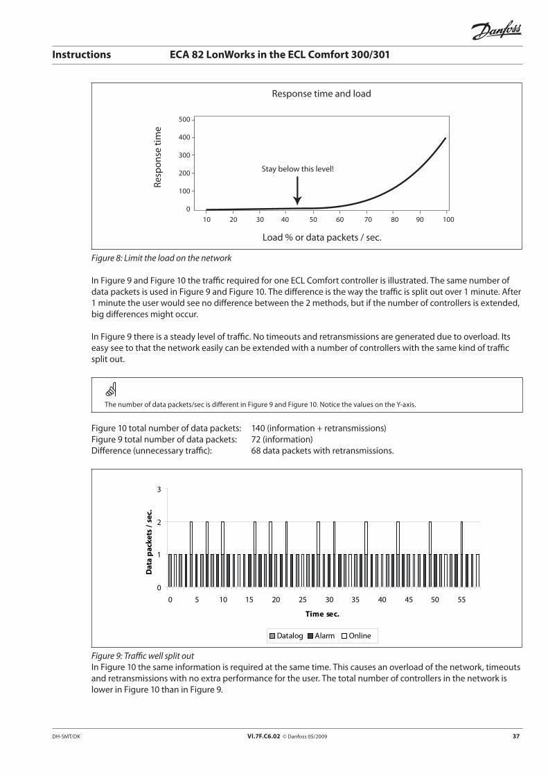
DH-SMT/DK VI.7F.C6.02 © Danfoss 05/2009 37
Instructions ECA 82 LonWorks in the ECL Comfort 300/301
Response time and load
Load % or data packets / sec.
Res
po
nse
tim
e
10 20 30 40 50 60 70 80 90 100
500
400
300
200
100
0
Stay below this level!
Figure 8: Limit the load on the network
In Figure 9 and Figure 10 the traffic required for one ECL Comfort controller is illustrated. The same number of data packets is used in Figure 9 and Figure 10. The difference is the way the traffic is split out over 1 minute. After 1 minute the user would see no difference between the 2 methods, but if the number of controllers is extended, big differences might occur.
In Figure 9 there is a steady level of traffic. No timeouts and retransmissions are generated due to overload. Its easy see to that the network easily can be extended with a number of controllers with the same kind of traffic split out.
The number of data packets/sec is different in Figure 9 and Figure 10. Notice the values on the Y-axis.
Figure 10 total number of data packets: 140 (information + retransmissions)Figure 9 total number of data packets: 72 (information)Difference (unnecessary traffic): 68 data packets with retransmissions.
0
1
2
3
0 5 10 15 20 25 30 35 40 45 50 55
Time sec.
Dat
a pa
cket
s / s
ec.
Datalog Alarm Online
Figure 9: Traffic well split outIn Figure 10 the same information is required at the same time. This causes an overload of the network, timeouts and retransmissions with no extra performance for the user. The total number of controllers in the network is lower in Figure 10 than in Figure 9.
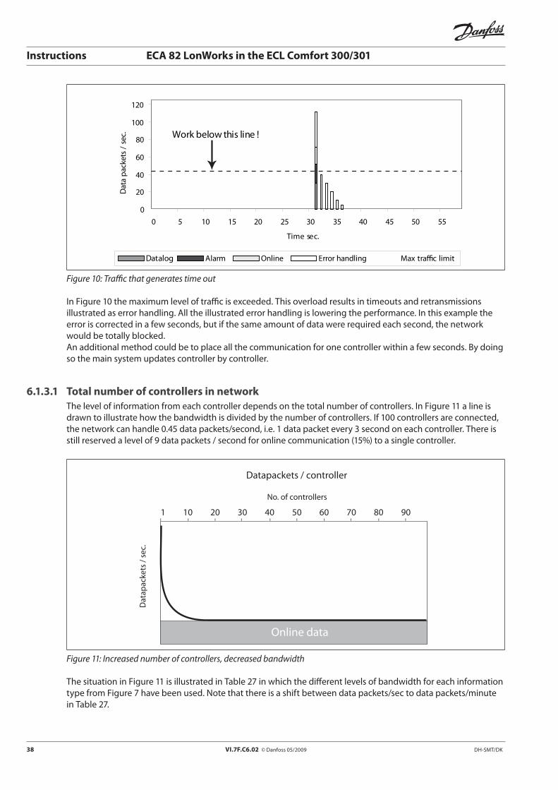
38 VI.7F.C6.02 © Danfoss 05/2009 DH-SMT/DK
Instructions ECA 82 LonWorks in the ECL Comfort 300/301
0
20
40
60
80
100
120
0 5 10 15 20 25 30 35 40 45 50 55
Time sec.
Dat
a pa
cket
s /
sec.
Datalog Alarm Online Error handling Max tra�c limit
Work below this line !
Figure 10: Traffic that generates time out
In Figure 10 the maximum level of traffic is exceeded. This overload results in timeouts and retransmissions illustrated as error handling. All the illustrated error handling is lowering the performance. In this example the error is corrected in a few seconds, but if the same amount of data were required each second, the network would be totally blocked. An additional method could be to place all the communication for one controller within a few seconds. By doing so the main system updates controller by controller.
6.1.3.1 Total number of controllers in networkThe level of information from each controller depends on the total number of controllers. In Figure 11 a line is drawn to illustrate how the bandwidth is divided by the number of controllers. If 100 controllers are connected, the network can handle 0.45 data packets/second, i.e. 1 data packet every 3 second on each controller. There is still reserved a level of 9 data packets / second for online communication (15%) to a single controller.
Online data
1 10 20 30 40 50 60 70 80 90
Datapackets / controller No. of controllers
Dat
apac
kets
/ se
c.
Figure 11: Increased number of controllers, decreased bandwidth
The situation in Figure 11 is illustrated in Table 27 in which the different levels of bandwidth for each information type from Figure 7 have been used. Note that there is a shift between data packets/sec to data packets/minute in Table 27.
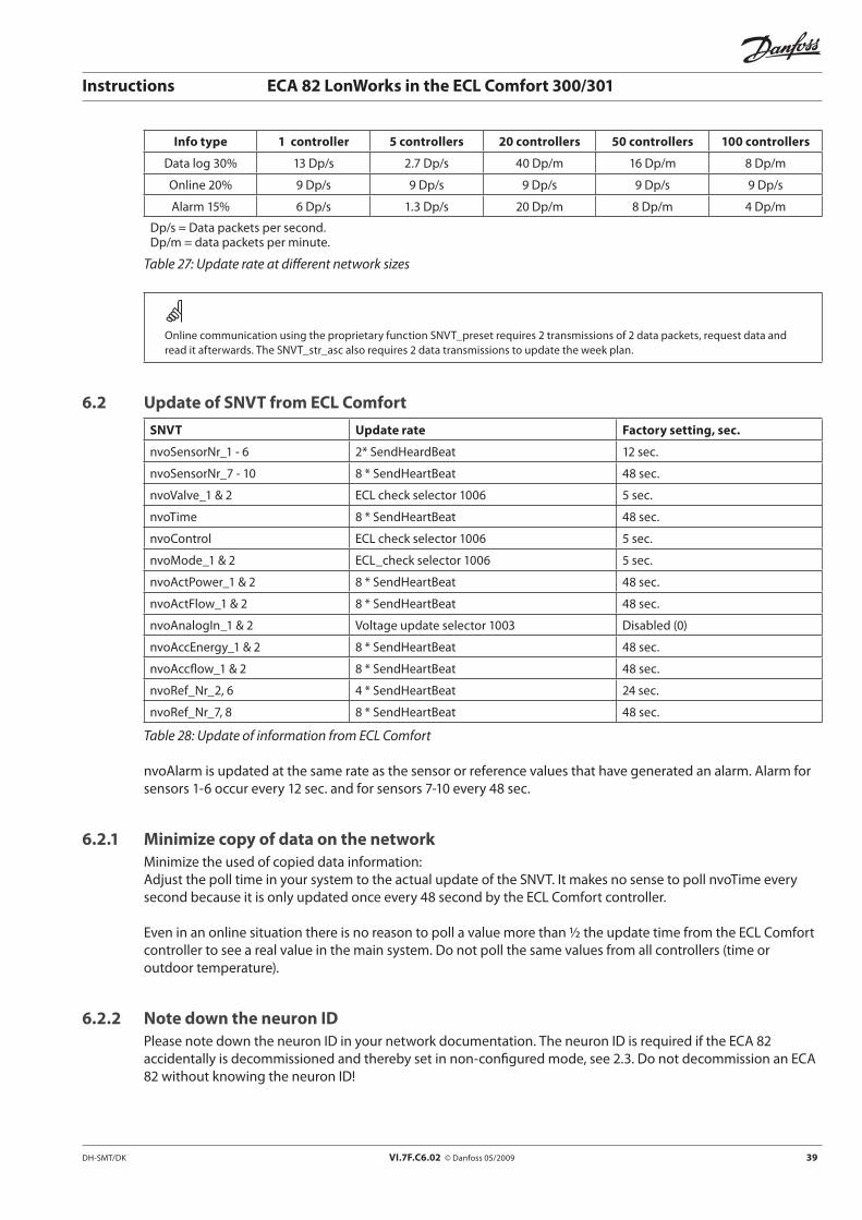
DH-SMT/DK VI.7F.C6.02 © Danfoss 05/2009 39
Instructions ECA 82 LonWorks in the ECL Comfort 300/301
Info type 1 controller 5 controllers 20 controllers 50 controllers 100 controllers
Data log 30% 13 Dp/s 2.7 Dp/s 40 Dp/m 16 Dp/m 8 Dp/m
Online 20% 9 Dp/s 9 Dp/s 9 Dp/s 9 Dp/s 9 Dp/s
Alarm 15% 6 Dp/s 1.3 Dp/s 20 Dp/m 8 Dp/m 4 Dp/m
Dp/s = Data packets per second. Dp/m = data packets per minute.
Table 27: Update rate at different network sizes
Online communication using the proprietary function SNVT_preset requires 2 transmissions of 2 data packets, request data and read it afterwards. The SNVT_str_asc also requires 2 data transmissions to update the week plan.
6.2 Update of SNVT from ECL Comfort
SNVT Update rate Factory setting, sec.
nvoSensorNr_1 - 6 2* SendHeardBeat 12 sec.
nvoSensorNr_7 - 10 8 * SendHeartBeat 48 sec.
nvoValve_1 & 2 ECL check selector 1006 5 sec.
nvoTime 8 * SendHeartBeat 48 sec.
nvoControl ECL check selector 1006 5 sec.
nvoMode_1 & 2 ECL_check selector 1006 5 sec.
nvoActPower_1 & 2 8 * SendHeartBeat 48 sec.
nvoActFlow_1 & 2 8 * SendHeartBeat 48 sec.
nvoAnalogIn_1 & 2 Voltage update selector 1003 Disabled (0)
nvoAccEnergy_1 & 2 8 * SendHeartBeat 48 sec.
nvoAccflow_1 & 2 8 * SendHeartBeat 48 sec.
nvoRef_Nr_2, 6 4 * SendHeartBeat 24 sec.
nvoRef_Nr_7, 8 8 * SendHeartBeat 48 sec.
Table 28: Update of information from ECL Comfort
nvoAlarm is updated at the same rate as the sensor or reference values that have generated an alarm. Alarm for sensors 1-6 occur every 12 sec. and for sensors 7-10 every 48 sec.
6.2.1 Minimize copy of data on the networkMinimize the used of copied data information: Adjust the poll time in your system to the actual update of the SNVT. It makes no sense to poll nvoTime every second because it is only updated once every 48 second by the ECL Comfort controller.
Even in an online situation there is no reason to poll a value more than ½ the update time from the ECL Comfort controller to see a real value in the main system. Do not poll the same values from all controllers (time or outdoor temperature).
6.2.2 Note down the neuron IDPlease note down the neuron ID in your network documentation. The neuron ID is required if the ECA 82 accidentally is decommissioned and thereby set in non-configured mode, see 2.3. Do not decommission an ECA 82withoutknowingtheneuronID!
VI.7F.C6.02 © Danfoss 05/2009 DH-SMT/DK
Instructions ECA 82 LonWorks in the ECL Comfort 300/301
*087R9522**VI7FC602*
Disposal instruction:
This product should be dismantled and its components sorted, if possible, in various groups before recycling or disposal.
Always follow the local disposal regulations.