ece 330 power circuits and … · mechanical energy into electric energy through a three- ......
TRANSCRIPT
ECE 330 POWER CIRCUITS AND
ELECTROMECHANICS
LECTURE 1
COURSE INTRODUCTION
AND REVIEW OF PHASORS
Acknowledgment-These handouts and lecture notes given in class are based on material from Prof. Peter
Sauer’s ECE 330 lecture notes. Some slides are taken from Ali Bazi’s presentations.
Disclaimer- These handouts only provide highlights and should not be used to replace the course textbook.
1/16/2018
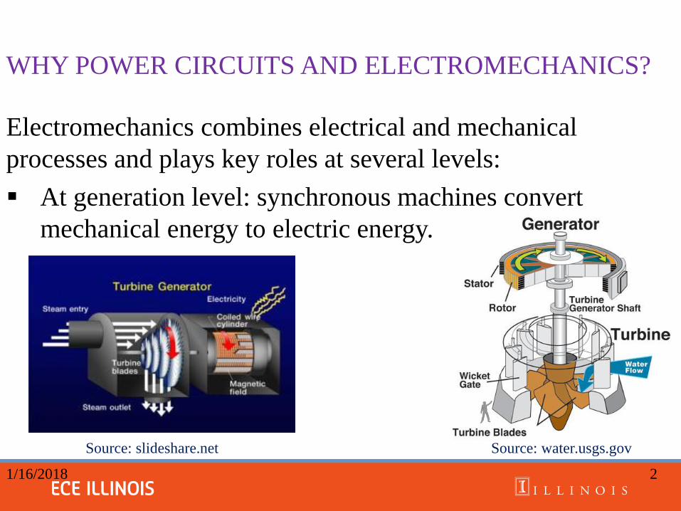
WHY POWER CIRCUITS AND ELECTROMECHANICS?
Electromechanics combines electrical and mechanical
processes and plays key roles at several levels:
At generation level: synchronous machines convert
mechanical energy to electric energy.
Source: slideshare.net Source: water.usgs.gov
1/16/2018 2

WHY POWER CIRCUITS AND ELECTROMECHANICS?
At transmission-distribution level: Circuit breakers trip the
faults in affected areas.
Source: abb.com Source: engineeringtutorial.com
1/16/2018 3
I
Ngxlp μ
μ
Xo
Core mean length: lc
Core area: Ac
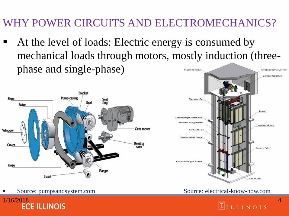
WHY POWER CIRCUITS AND ELECTROMECHANICS?
At the level of loads: Electric energy is consumed by
mechanical loads through motors, mostly induction (three-
phase and single-phase)
Source: pumpsandsystem.com Source: electrical-know-how.com
1/16/2018
4

WHY POWER CIRCUITS AND ELECTROMECHANICS ?
In advanced technology: renewable energy, electric cars,
robots,….. etc. contain electromechanic systems.
Wind Turbine Electric Vehicle Robot
Source: energy.gov Source: exchangeev.aaa.co m Source: yaskawa.co.jp
1/16/2018 5

Goals:
To impart basics of three-phase power circuits, transformers,
electromechanical systems, and rotating machines.
Objectives:
To build cognitive skills, such as analytical thinking and
problem solving. The course integrates fundamentals of
advanced math and science to enhance the ability to design a
system and meet desired needs.
1/16/2018
6
POWER CIRCUITS AND ELECTROMECHANICS
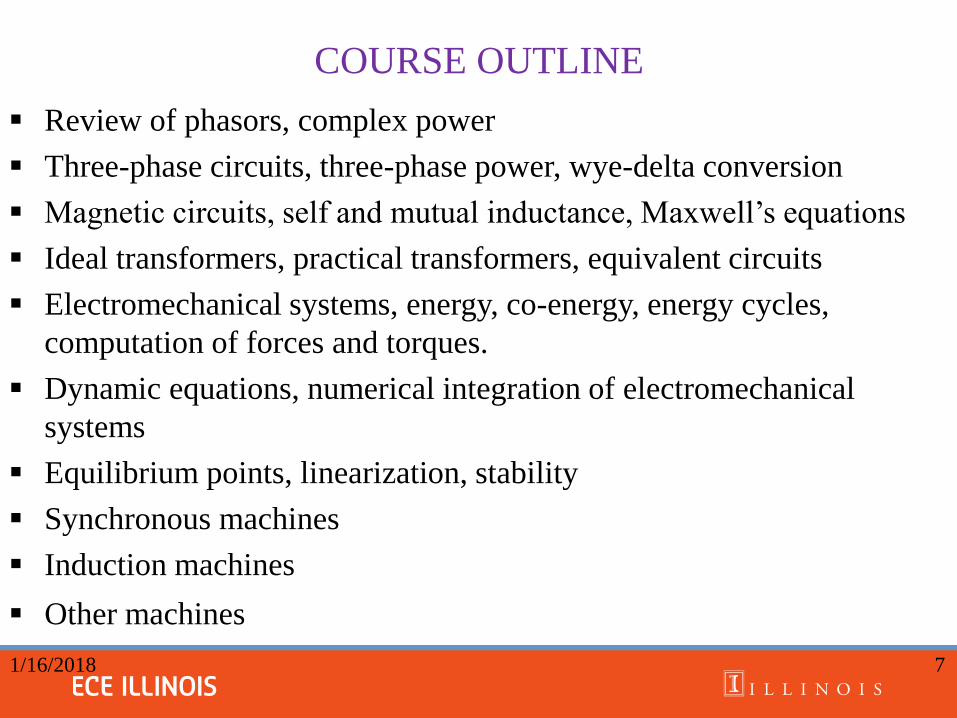
COURSE OUTLINE
Review of phasors, complex power
Three-phase circuits, three-phase power, wye-delta conversion
Magnetic circuits, self and mutual inductance, Maxwell’s equations
Ideal transformers, practical transformers, equivalent circuits
Electromechanical systems, energy, co-energy, energy cycles,
computation of forces and torques.
Dynamic equations, numerical integration of electromechanical
systems
Equilibrium points, linearization, stability
Synchronous machines
Induction machines
Other machines
1/16/2018 7

STRUCTURE OF POWER SYSTEMS
• Power system’s main components: generation, transmission,
distribution, and loads.
Source: image.slidesharecdn.com
1/16/2018 8
STRUCTURE OF POWER SYSTEMS
Generating System:
The generating system consists of a fuel source such as
coal, water, natural gas or nuclear power.
Hydropower accounts for about 8%, and nuclear power
20%, renewable energy 14% of electric energy production
in the US.
The turbine acting as the prime-mover converts
mechanical energy into electric energy through a three-
phase synchronous machine.
The three-phase voltages of the generators range from
13.8 kV to 24 kV.
1/16/2018 9
STRUCTURE OF POWER SYSTEMS
Transmission System:
A three-phase transformer at each generator steps up the
voltage to a high value ranging from 138 kV to 765 kV.
The transmission lines carry power over these lines to load
centers and, where appropriate, step it down to lower
voltages up to 34 kV at the bulk-power substations.
Some industrial customers are supplied from these
substations. This is known as the transmission—sub-
transmission system.
1/16/2018 10
STRUCTURE OF POWER SYSTEMS
Distribution System:
Transformers step down the voltage to a range of 2.4 kV to
69 kV.
Power is carried by main feeders to specific areas where
there are lateral feeders to step it down further to customer
levels, such as 208, 240, or 600 volts.
The distribution transformers serve anywhere from 1 to 10
customers.
11 1/16/2018
STRUCTURE OF POWER SYSTEMS
The classes of entities in the electricity market are:
Generator companies (GENCOs), also called
independent power producers (IPPs).
Transmission companies TRANSCOs,
Their primary responsibility is to transport power
from generators to customers and make the
transmission system available to all.
12 1/16/2018
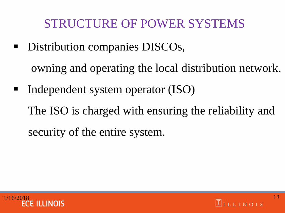
STRUCTURE OF POWER SYSTEMS
Distribution companies DISCOs,
owning and operating the local distribution network.
Independent system operator (ISO)
The ISO is charged with ensuring the reliability and
security of the entire system.
13 1/16/2018
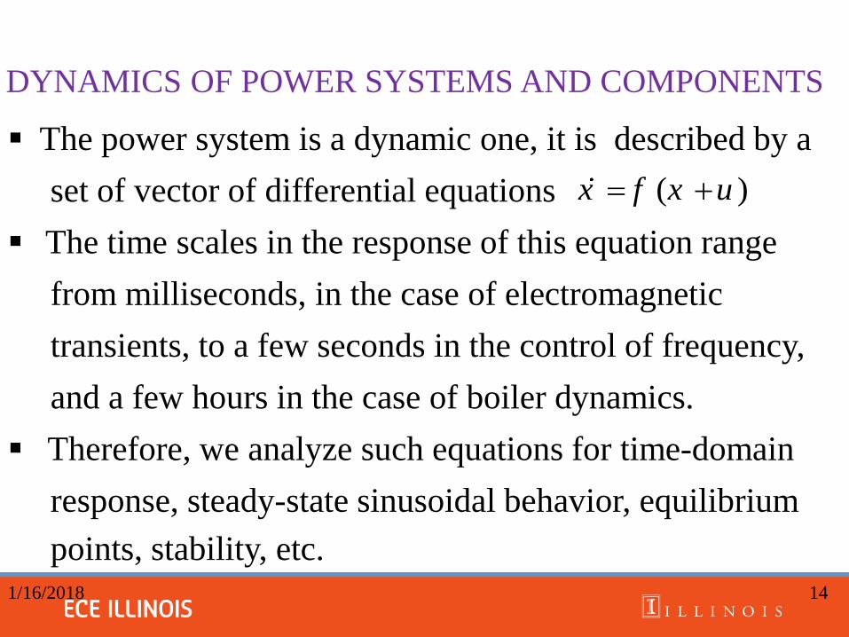
DYNAMICS OF POWER SYSTEMS AND COMPONENTS
The power system is a dynamic one, it is described by a
set of vector of differential equations
The time scales in the response of this equation range
from milliseconds, in the case of electromagnetic
transients, to a few seconds in the control of frequency,
and a few hours in the case of boiler dynamics.
Therefore, we analyze such equations for time-domain
response, steady-state sinusoidal behavior, equilibrium
points, stability, etc. 1/16/2018 14
( )x f x u
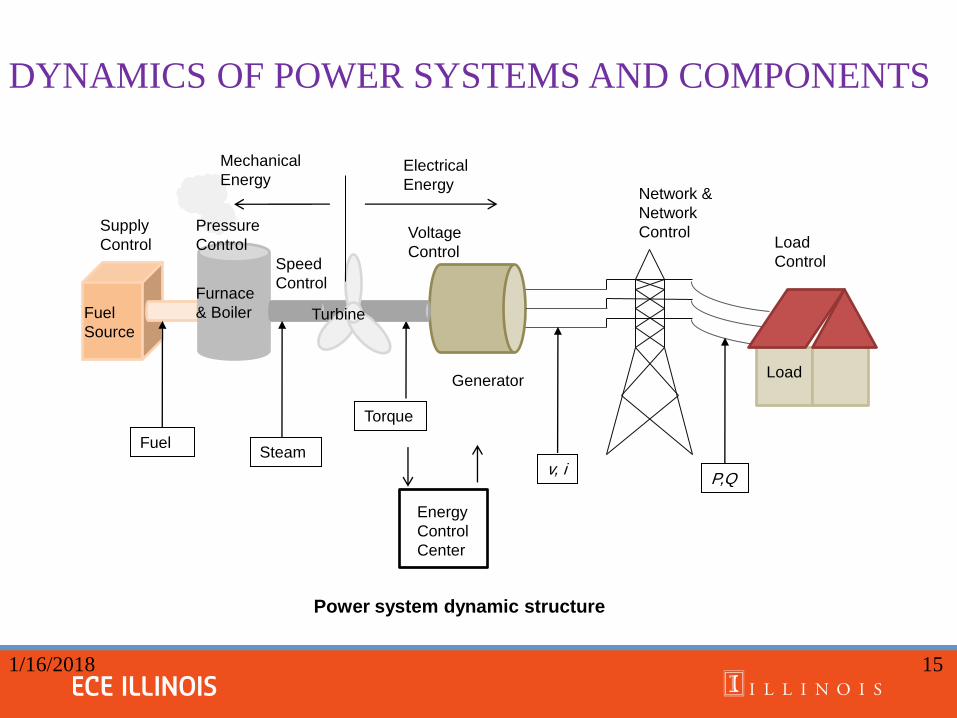
DYNAMICS OF POWER SYSTEMS AND COMPONENTS
15 1/16/2018
Power system dynamic structure
v, i
Fuel
Source
Furnace
& Boiler Turbine
Generator
Fuel Steam
Torque
Electrical
Energy
Mechanical
Energy
Supply
Control
Pressure
Control
Speed
Control
Voltage
Control
Network &
Network
Control
Load
P,Q
Load
Control
Energy
Control
Center

DYNAMICS OF POWER SYSTEMS AND COMPONENTS
Diagram does not show all the complex dynamic
interaction between components and their controls.
Electrical side contains mechanical dynamics(TCUL)
Mechanical side contains components with electrical
dynamics (electrical valves)
After the model is derived we put it in the state-space
form.
1/16/2018 16

REVIEW OF PHASORS
• Phasors represent quantities with magnitude and angle
with respect to a reference and are commonly used in
energy systems.
• Example:
Euler’s expansion:
Then, v (t ) can be written as
where is the RMS phasor with
cosine reference. 1/16/2018 17
( ) cos ( )m vv t V t
cos( ) sin( )je j
( )( ) Re{ } Re{ } Re{ 2 }v vj t jj t j t
m mv t V e V e e Ve
2
vmrms v
jVV e V
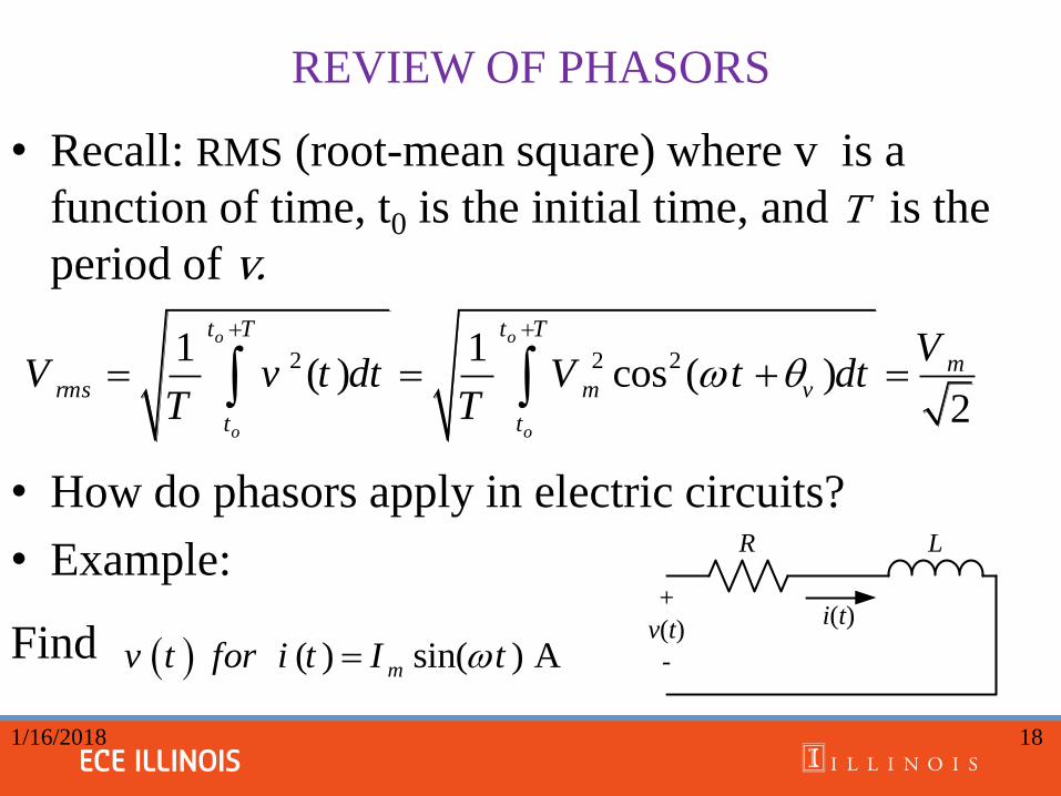
REVIEW OF PHASORS
• Recall: RMS (root-mean square) where v is a
function of time, t0 is the initial time, and T is the
period of v.
• How do phasors apply in electric circuits?
• Example:
Find
1/16/2018 18
2 2 21 1( ) cos ( )
2
o o
o o
t T t T
mrms m v
t t
VV v t dt V t dt
T T
R L
+
v(t)
-
i(t)
( ) sin( ) Amv t for i t I t
REVIEW OF PHASORS
1/16/2018 19
R L
+
v(t)
-
i(t)
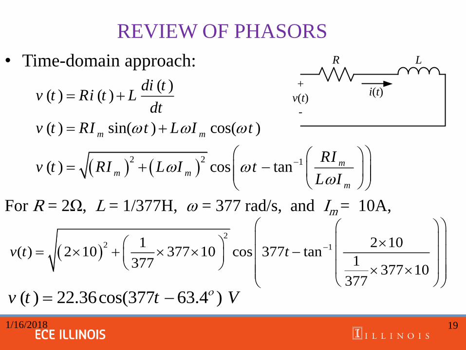
• Time-domain approach:
For R = 2Ω, L = 1/377H, ω = 377 rad/s, and Im = 10A,
2
2 11 2 10( ) 2 10 377 10 cos 377 tan
1377377 10
377
v t t
2 2 1
( )( ) ( )
( ) sin( ) cos( )
( ) cos tan
m m
mm m
m
di tv t Ri t L
dt
v t RI t L I t
RIv t RI L I t
L I
( ) 22.36cos(377 63.4 )v t t V
REVIEW OF PHASORS
20
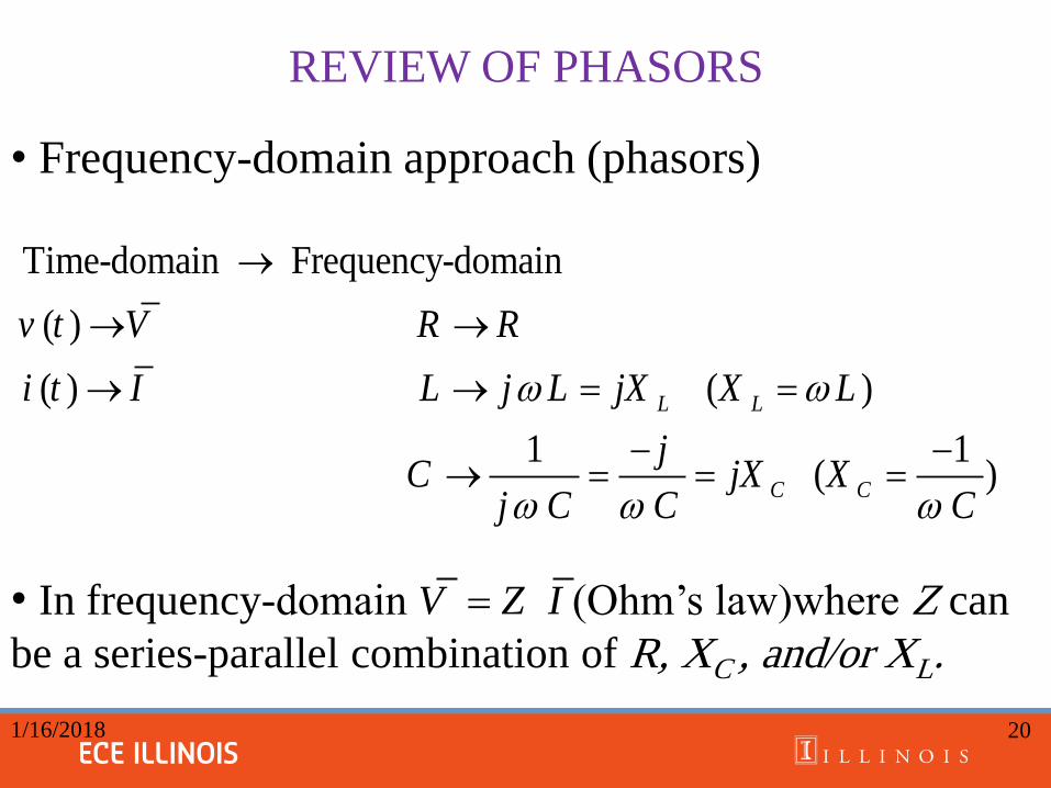
• Frequency-domain approach (phasors)
• In frequency-domain (Ohm’s law)where Z can
be a series-parallel combination of R, XC , and/or XL.
Time-domain Frequency-domain
( )
( ) ( )
1 1 ( )
L L
C C
v t V R R
i t I L j L jX X L
jC jX X
j C C C
V Z I
1/16/2018
REVIEW OF PHASORS
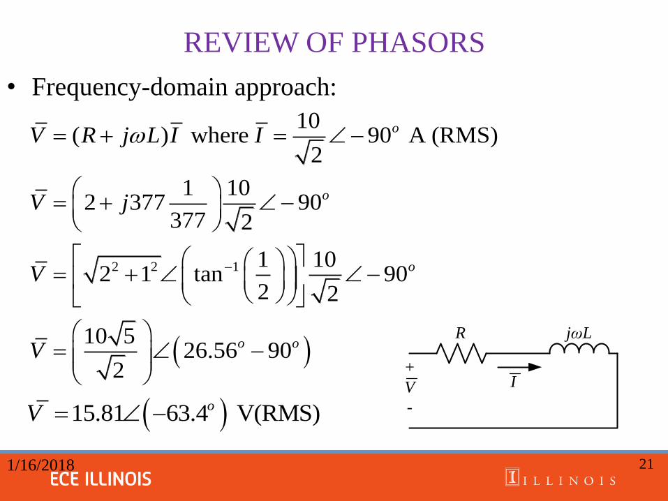
1/16/2018 21
R jωL
+
V
-
I
• Frequency-domain approach:
2 2 1
10( ) where 90 A (RMS)
2
1 102 377 90
377 2
1 102 1 tan 90
2 2
10 526.56 90
2
o
o
o
o o
V R j L I I
V j
V
V
15.81 63.4 V(RMS)oV
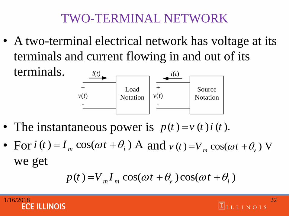
TWO-TERMINAL NETWORK
• A two-terminal electrical network has voltage at its
terminals and current flowing in and out of its
terminals.
• The instantaneous power is
• For and
we get
1/16/2018 22
( ) ( ) ( ).p t v t i t
+
v(t)
-
i(t)
Load
Notation
Source
Notation
+
v(t)
-
i(t)
( ) cos( ) Am ii t I t ( ) cos( ) Vm vv t V t
( ) cos( )cos( )m m v ip t V I t t
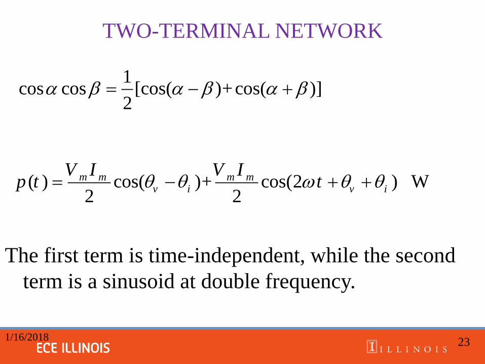
TWO-TERMINAL NETWORK
The first term is time-independent, while the second
term is a sinusoid at double frequency.
1/16/2018 23
( ) cos( )+ cos(2 ) W2 2
m m m mv i v i
V I V Ip t t
1cos cos [cos( )+cos( )]
2
TWO-TERMINAL NETWORK
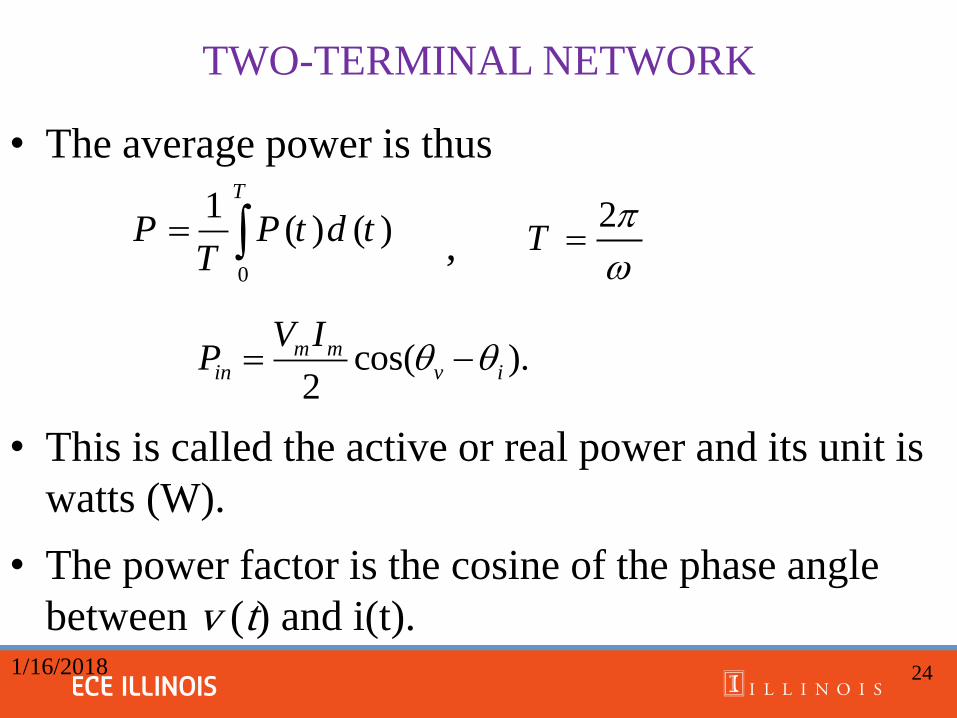
• The average power is thus
,
• This is called the active or real power and its unit is
watts (W).
• The power factor is the cosine of the phase angle
between v (t) and i(t). 1/16/2018 24
cos( ).2
m min v i
V IP
0
1( ) ( )
T
P P t d tT
2
T
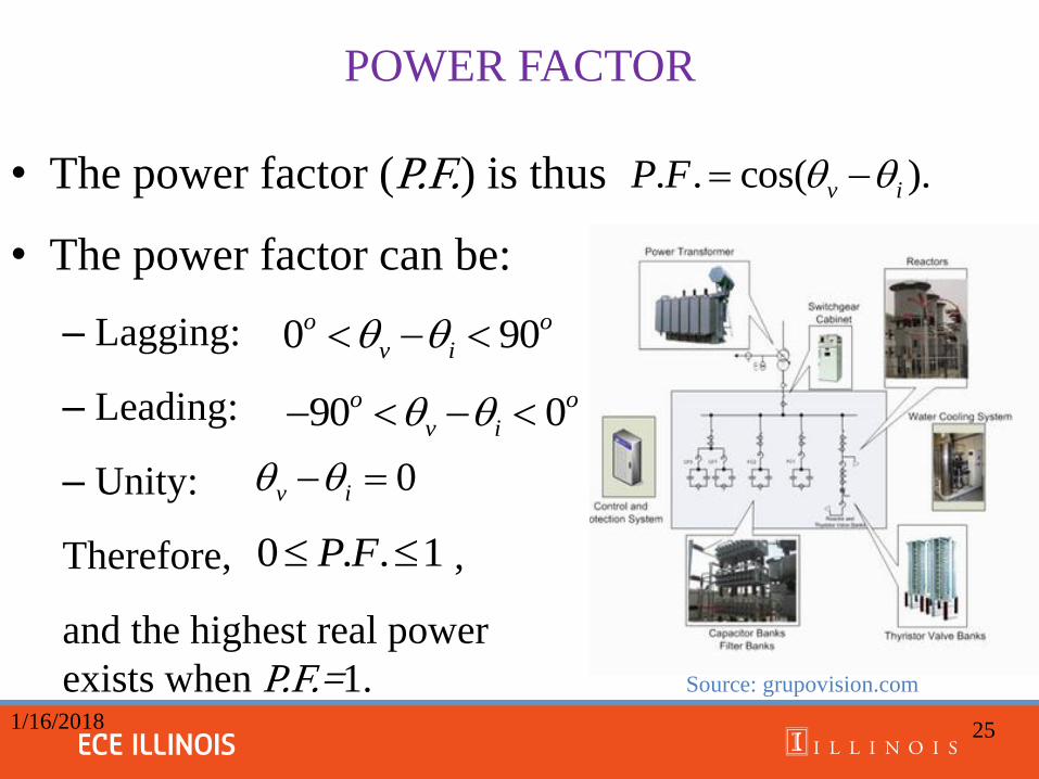
POWER FACTOR
• The power factor (P.F.) is thus
• The power factor can be:
– Lagging:
– Leading:
– Unity:
Therefore, ,
and the highest real power
exists when P.F.=1. Source: grupovision.com
1/16/2018 25
. . cos( ).v iP F
0 90o o
v i
90 0o o
v i
0v i
0 . . 1P F
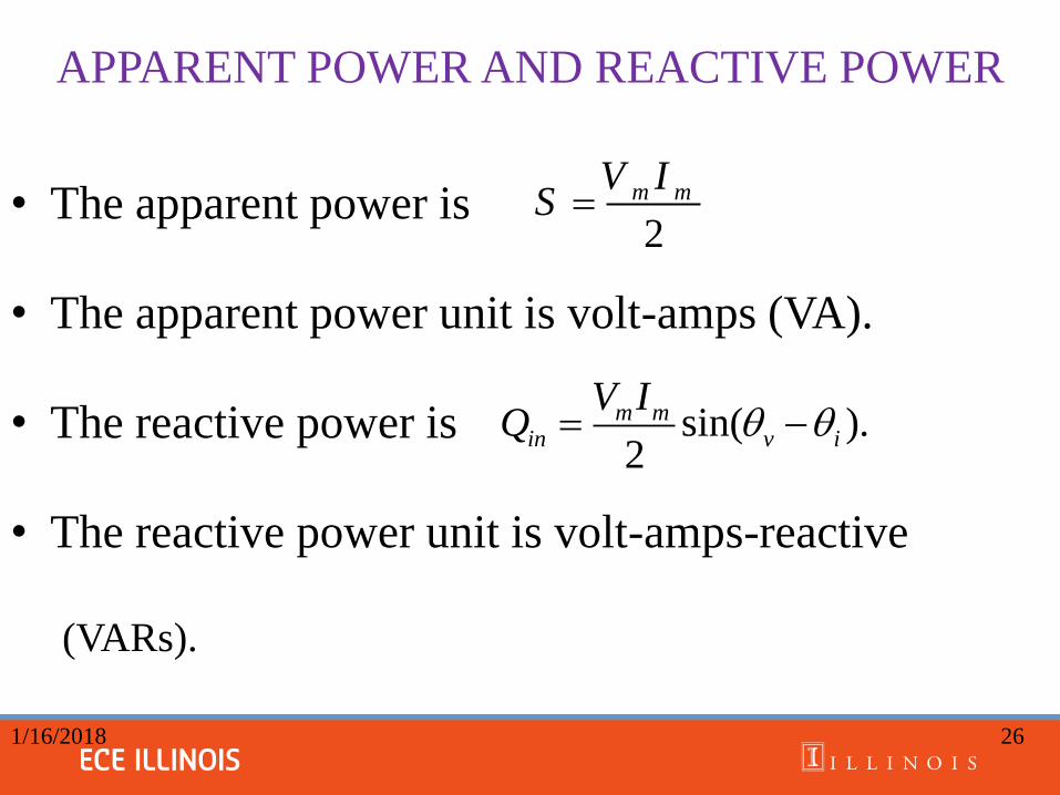
APPARENT POWER AND REACTIVE POWER
• The apparent power is
• The apparent power unit is volt-amps (VA).
• The reactive power is
• The reactive power unit is volt-amps-reactive
(VARs).
1/16/2018 26
sin( ).2
m min v i
V IQ
2
m mV IS
COMPLEX POWER
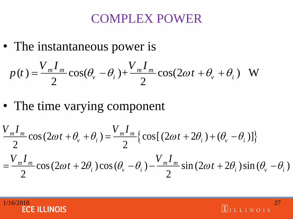
• The instantaneous power is
• The time varying component
1/16/2018 27
( ) cos( )+ cos(2 ) W2 2
m m m mv i v i
V I V Ip t t
cos (2 ) cos[ (2 2 ) ( )]2 2
cos (2 2 )cos ( ) sin (2 2 )sin ( )2 2
m m m mv i i v i
m m m mi v i i v i
V I V It t
V I V It t
COMPLEX POWER
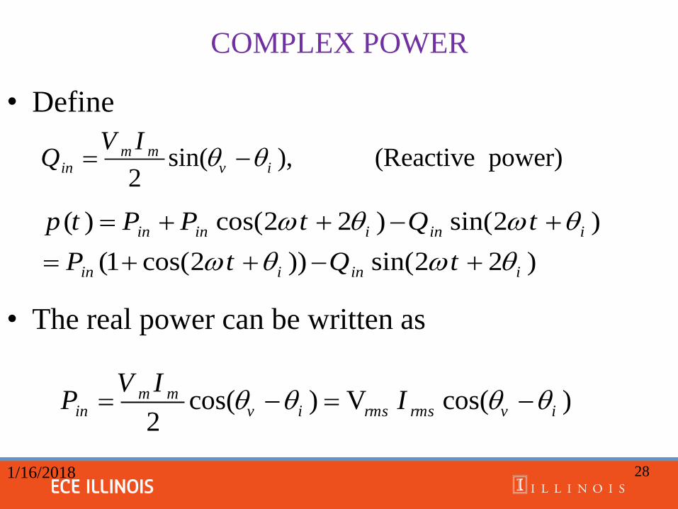
• Define
• The real power can be written as
1/16/2018 28
sin( ), (Reactive power)2
m min v i
V IQ
( ) cos(2 2 ) sin(2 )
(1 cos(2 )) sin(2 2 )
in in i in i
in i in i
p t P P t Q t
P t Q t
cos( ) V cos( )2
m min v i rms rms v i
V IP I
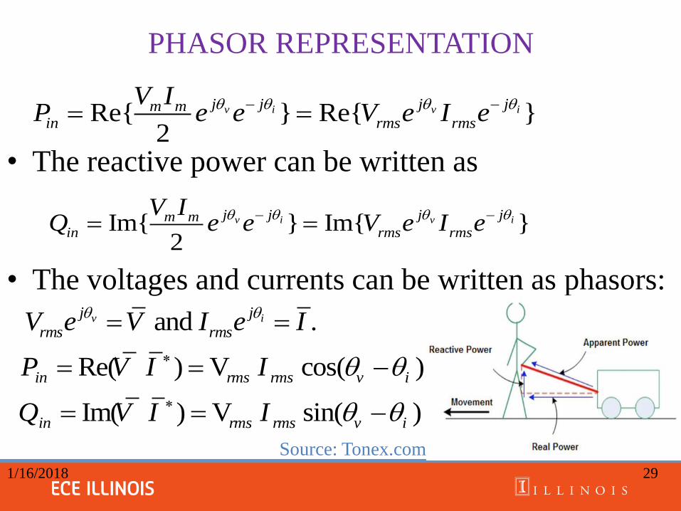
PHASOR REPRESENTATION
• The reactive power can be written as
• The voltages and currents can be written as phasors:
Source: Tonex.com
1/16/2018 29
Re{ } Re{ }2
v i v ij j j jm min rms rms
V IP e e V e I e
Im{ } Im{ }2
v i v ij j j jm min rms rms
V IQ e e V e I e
and .v ij j
rms rmsV e V I e I
Re( ) V cos( )in rms rms v iP V I I
Im( ) V sin( )in rms rms v iQ V I I
Complex Power
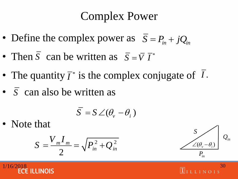
• Define the complex power as
• Then can be written as
• The quantity is the complex conjugate of
• can also be written as
• Note that
1/16/2018 30
in inS P jQ
* S V I
*I .I
( )v iS S
S
S
2 2
2
m min in
V IS P Q
S
inP
inQ
( )v i
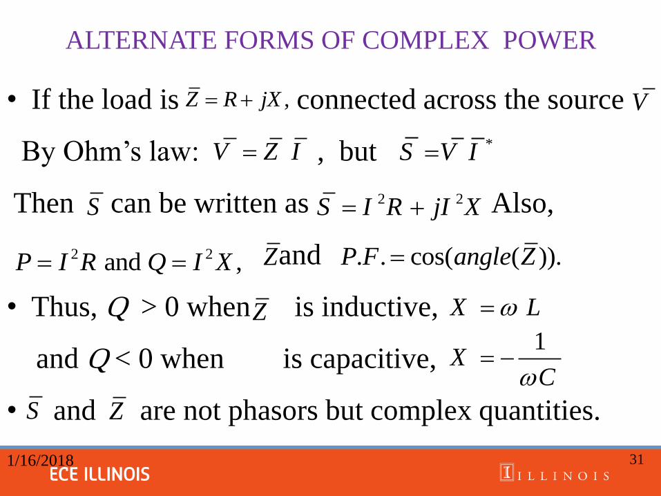
ALTERNATE FORMS OF COMPLEX POWER
• If the load is connected across the source
By Ohm’s law: , but
Then can be written as Also,
and
• Thus, Q > 0 when is inductive,
and Q < 0 when is capacitive,
• and are not phasors but complex quantities.
1/16/2018 31
,Z R jX
2 2S I R jI X
S
S
V Z I
Z
2 2 and ,P I R Q I X Z
Z
. . cos( ( )).P F angle Z
X L
1X
C
V
*S V I
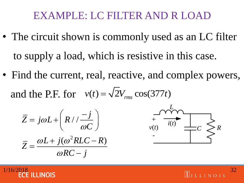
EXAMPLE: LC FILTER AND R LOAD
• The circuit shown is commonly used as an LC filter
to supply a load, which is resistive in this case.
• Find the current, real, reactive, and complex powers,
and the P.F. for
1/16/2018 32
2
/ /
( )
jZ j L R
C
L j RLC RZ
RC j
R
L
+
v(t)
-
i(t)C
( ) 2 cos(377 )rmsv t V t

EXAMPLE: LC FILTER AND R LOAD
• Let
1/16/2018 33
*
0.0197 39.41 0.0152 0.0125
120 06091.4 39.41 A
0.0197 39.41
( ) 6091.4 2 cos(377 39.41 )
731 39.41 kVA
731cos( 39.41 ) 564.8kW
731sin( 39.41 ) 464.1kVAR
P.F.= cos( 39.41 ) 0.77
o
oo
o
o
o
o
in
o
in
o
Z j
VI
Z
i t t
S V I
P
Q
3 leading ( 39.41 )o
v i
R
L
+
v(t)
-
i(t)C
120 , 1mH, 6.8mF, and R 10 .rmsV V L C