eclipse e600 pol
TRANSCRIPT

Polarizing Microscope
ECLIPSE E600 POL Instructions

I Thank you for purchasing the Nikon products. This instruction manual is written for the users of the Nikon Polarizing Microscope ECLIPSE E600 POL. To ensure correct usage. read this manual carefully before operating the instrument.
• It is prohibited to reproduce or transmit this manual in part or whole without Nikon·s expressed permission.
• The contents of this manual are subject to change without notice. • Some of the products described in this manual may not be included in the set you
have purchased. • Although every effort has been made to ensure the accuracy of this manual. if you
note any points that are unclear or incorrect. contact your nearest Nikon
representative.
Warning/Caution Symbols Used in This Manual
Although Nikon products are designed to provide you with the utmost safety during use. incorrect usage or disregard of the instructions can cause personal injury or property damage. For your safety. read the instruction manual carefully and thoroughly before using the instrument. Do not discard this manual but keep it near the product for easy reference. In this manual. safety instructions are indicated with the symbols shown below. Be sure to follow the instructions indicated with these symbols to ensure correct and safe operation.
Symbol
&WARNING
&CAUTION
Meaning
Disregarding instructions marked with this symbol may lead to death or serious injury.
Disregarding instructions marked with this symbol may lead to injury or property damage.
Meaning of Symbols Used on the Equipment
Symbol Meaning
Caution for heat. This marking near the lamphouse calls your attention on the following: • Lamphouse becomes very hot during and immediately
after the illumination. • Risk of burns. Do not touch the lamphouse during and
immediately after the illumination. • Make sure that the lamphouse is sufficiently cool before
the lamp replacement.

&WARNING
2
1. Intended product use This microscope should only be used for microscopic observation. Do not use it for any other purpose.
2. Do not disassemble Disassembling may cause malfunction and/or electrical shock. Do not disassemhle any pans other than those mentioned in this manual. If you notice any malfunction. notify your nearest Nikon representative.
3. Input voltage Make sure that the input voltage indicated on the back panel of the microscope is the same as your regional voltage. If not the same. do not use the microscope; instead. notify your nearest Nikon representative immediately. If the microscope is used with the wrong input voltage. a short circuit or fire may result. causing the damage of the microscope.
4. Power cord To prevent electrical shock. always turn off the power switch (flip it to the" 0" side) before connecting or disconnecting the power cord. Use only the following power supply cord set. Using the wrong power cord could result in damage or fire. • For I OO- I 20V area
UL Listed. detachable cord set. 3 conductor grounding type SVT, No. 18 AWG rated at 125V, 7A minimum.
Nllton MODEL ECLIPSE E600 POL
430001
In case of using the extension cord. use only the power supply cord with the PE (protective earth) wire.
• For 220-240V area 3 pole power supply cord set. which must be approved according to EU/EN standards. . Class I equipment should be connected to PE (protective earth) terminal. In case of using the extension cord. use only the power supply cord with the PE (protective earth) wire.
5. Heat from the light source The lamp and the lamphouse become extremely hot. To avoid burns. do not touch the lamphouse while the lamp is lit or for thirty minutes after it has been turned off. Furthermore. in order to avoid the risk of fire. do not place fabric, paper or highly flammable materials such as gasoline, petroleum benzine. paint thinner or alcohol near the lamphouse while it is lit or for about thirty minutes after it has been turned off. The back of the microscope also becomes hot during use. Although this is not a malfunction. be careful not to touch the back of the microscope when it is hot.

&CAUTION
1. Only use the specified halogen lamp The power supply unit in the microscope provides the power for the halogen lamp that serves as the microscope light source. This unit can supply power for a halogen lamp of up to 12V-IOOW. The specified lamp and lamphouse must be used. otherwise. the microscope could be damaged.
Specified lamphouse (for diascopic use): Nikon C-LP HALOGEN 12VIOOW model
Specified lamphouse (for episcopic use): Nikon LHS-HIOOP-2 HALOGEN 12VIOOW model
Specified lamp (for both diascopic and episcopic uses): I 2V- I OOW LONG LIFE halogen lamp (OS RAM HLXM62.~ or PHILIPS 7724 l
2. Precautions for replacing the lamp To prevent burns. allow the lamp to cool for at least thirty minutes after turning off the power switch before replacing it. Furthermore. to prevent electrical shock. and damage to
the microscope. always turn off the power switch (flip it to the·· ::_: ·· side) and unplug the power cord before connecting or disconnecting the lamphouse. After replacing the lamp. he sure to attach the lamphouse cover securely. Never use the lamphouse without its cover.
3. Do not wet the microscope If the microscope gets wet. a short circuit may result that could damage it or make it extremely hot. If you accidentally spill a liquid on the microscope. immediately turn off the power switch (flip it to the" 0" side) and unplug the power cord. Then use a dry cloth to wipe away the moisture. If any liquid gets inside the microscope. do not use it: instead. notify your nearest Nikon representative.
4. Weak electromagnetic waves This microscope emits weak electromagnetic waves. The accuracy of any precision electronic equipment may he adversely affected if positioned too close. If the microscope affects TV or radio reception. move the radio or TV further away from the microscope.
5. Precautions for installation Be careful not to pinch your hands or fingers when installing the microscope. This microscope is a precision optical instrument. and using or storing it under unsuitable conditions may damage it or may have an adverse effect on its accuracy. See "Installation location" on p. 32 and always use the microscope in a suitable environment.
6. Precautions for moving the microscope First detach the lamphouse. and then securely hold the microscope hy the hase of the arm from the back. Do not grasp the focus knobs. eyepiece tube. stage. etc. when carrying the microscope. This could cause the part to come off. resulling in damage to the microscope. This microscope is a precision optical instrument. so handle it carefully and do not subject it to a strong physical shock. (The accuracy of the ohjective in particular may be adversely affected by even a weak physical shock.)
3

CONTENTS
Warning/Caution Symbols Used in This Manual ......................................................... 1
& WARNING ................................................................................................................... 2
& CAUTION .................................................................................................................... 3
D Names of Component Parts and Operational Parts ............................................. 6
Iii Microscopic Procedure ........................................................................................... 8 D Diascopic Illumination Microscopy .................................................................................. 8
El Episcopic Illumination Microscopy ................................................................................. I 3
II Orthoscopic Observation/Conoscopic Observation ........................................................ I 7
D Operation of Each Part ......................................................................................... 18 D Coarse and fine focus knobs ..... .. ... . .. ... ... ... .. . ....... ....... ............ .. . ... . . . . . . .. . . .. . . . . . . . . . .. .. . .. . .. . . . . 18
I. Rotation of the coarse and fine focus knobs and vertical movement of the stage .... 18
2. Adjusting the torque of the coarse focus knob ........................................................... 18
3. Coarse focus stopper ................................................................................................... 19
El Trinocular eyepiece tube .................................................................................................. 20
1. Optical path selection ................................................................................................. 20
2. Vertical tube adapter ................................................................................................... 20
3. Optical path selection lever clicking .......................................................................... 20 II Diopter adjustment ........................................................................................................... 21 D Interpupillary distance adjustment ................................................................................... 21
II Condenser ......................................................................................................................... 22
1. Focusing and centering ............................................................................................... 22
2. Condenser aperture diaphragm ................................................................................... 23
3. Swing-out the top lens of the condenser .................................................................... 24
Iii Field diaphragm ............................................................................................................... 24
I.I Filters ................................................................................................................................ 24
Iii Auto-photo switch (for photomicrography) .................................................................... 25
Iii Oil-immersion operation (using an oil-immersion type of objective and condenser) .... 25
mJ Orientation of polarizing plates (Polarizer and Analyzer) .........................................•.... 26
m Focusing and centering the Benrand lens ........................................................................ 28
18 P-CL l/4A. & tint plate ..................................................................................................... 28
Ill Centering the objectives ................................................................................................... 28
ID Circular graduated stage for polarizing microscope ........................................................ 29
ml Use of optional accessories (Sold Separately) ................................................................. 29
1. P-CS Senarmont Compensator ................................................................................... 29
'"' P-CQ Quartz wedge .................................................................................................... 30
3. Attachable Mechanical Stage ..................................................................................... 31
III Assembly ............................................................................................................... 32
~Troubleshooting Tables ........................................................................................ 41
n Care and Maintenance .......................................................................................... 45
H Specifications and Standards .............................................................................. 46
5

Names of Component Parts and Operational Parts
If the microscope has not yet been assembled. see chapter .. 4. Assembly'" first.
Polarizing intermediate tube
Bertrand lens centering screw
45° click-stop lever
screw
Coarse torque adjustment ring (TORQUE)
Coarse focus knob
Fine focus knob
Brightness adjuster (LAMP)
Auto-photo switch
Auto-photo voltage selection switch
6
Photomicrographic vertical tube adapter
Trinocular eyepiecetube
Eyepiece
Diopter adjustment ring
Analyzer slider
P-CL 1 /4'A & tint plate
Revolving nosepiece
Objective centering screws
Objective
Stage rotation clamp screw
Vernier
Specimen clip
Circular graduated stage
Dia-polarizer (Inside lhe bottom of !he condenser)

Bertrand lens turret
Bertrand lens focus ring
Condenser top lens swing-out knob
Condenser aperture scale
Condenser aperture diaphragm ring
Swing-out condenser
Condenser centering screws
Field lens
Field diaphragm ring
Epi/Dia changeover switch
Tool holder (Holds a hexagonal screWdnver. a hexagonal wrench and two centenng screws.)
AC input connector
Power cord
1. Names of Component Parts and Operational Parts 1'
(Rear)
Photomicrographic equipment clamp screw
Optical path selection lever
Eyepiece tube clamp screw
Intermediate tube clamp screw
Revolving nosepiece clamp screw
Substage clamp scr~vv
Filter release lever
Diffuser insertion/ removal screw
Epi-illuminator connector
Rating label
Lamphouse
7

8
Microscopic Procedure
The general procedure for microscopy is described below. For details on each step. refer to the corresponding item in chapter .. 3. Operation of Each Part." If the microscope has not yet been assembled. see chapter "4. Assembly .. first.
1 Diascopic Illumination Microscopy
D Turn the Epi/Dia changeover switch on the back of the microscope stand to the DIA position.
a Turn on the power. Kii:I (Flip the switch to the .. I •. side.)
As soon as the power comes on. the switch lights.
1:'11 Set the brightness adjuster to a give the desired brightness. Pressing the auto-photo switch will set the voltage for the brightness that provides the best color reproduction. (p.25)
B Insert filters ND32 or 8 and U NCB 11 into the optical path.
ND32 or 8 reduces glare in the binocular eyepiece. NCB 11 improves color reproduction. (p.24)
a Push in the analyzer slider of the a intermediate tube to remove the ~ivi:v, analyzer from the optical path. ··~· i'·.·.;.··~;.
;.:i~j:
1'!!9 Put the Bertrand lens turret in the a .. 0 .. position to remove the Bertrand lens from the optical path.
II Insert filters. ,_,~
II Adjust the brightness. ~ ·~,~ Auto-photo switch can be pressed _!
1-11 Push in the , analyzer
/
~' -1'1 Turn the turret to the "O" position.
slider.

n Move the !OX objective into the .. optical path.
Rotate the revolving nosepiece ,,, until the !Ox objective clicks
into place.
n Set the specimen in place with ... the cover glass facing up.
Raise the condenser as high as it will go.
rr.i. Fully open the field diaphragm ~ and condenser apenure
diaphragm.
II Set the
2. Microscopic Procedure I -D Set the 10x
objective.
---
~ U!J Fully open the field diaphragm.
9

10
m ~oosen the coarse focus stopper nng. Rotate it in the direction opposite the arrow on the base as far as it will go. (p.19)
m Set t~e optical path to I 00</t of lliii:ll the bmocular eyepiece when · · using the trinocular eyepiece
tube. (p.20)
m Turn the diopter adjustment ring 11iii1 of the right eyepiece (containing
the crosshairs) and focus on the crosshairs.
Focus on the specimen. (p.18)
I I I
, I i $]
m Loosen the coarse focus stopper.
!:
DJ Focus on the reticle crosshairs.
Im Set the optical path to 100% of the binocular eyepiece.
ID Focu~ on the specimen.

. f the left m Adjust the diopter o lli:il eyepiece. (p.2 I)
· terpupillary 1!P-9 Adjust the m ll:il distance. (P-21 )
. . (p 28) the objecuve. · m Center
the condenser. m Focus and center .... (p.22)
\ / v .
ID Center the objective.
· p cedure I 2. Microscopic ro
_ Im Adjust the diopter nng.
Im Adjust the interpupillary distance.
h ondenser. Im Center t e c =-------
11

12
m Switch to any desired objective l&;I and view the specimen. j,.. Rotate the revolving nosepiece to
its click-stop position. In the case of using an oilimmersion objective. apply oil while being careful that air bubbles do not form between the end of the objective and the specimen.
Manipulate the coarse focus knob or fine focus knob to refocus on the specimen.
Manipulate the ND filter insertion lever to adjust the brightness. (When adjusting the lamp brightness. turn off the autophoto switch and manipulate the brightness adjuster.)
Close the field diaphragm so that it is just outside the field of view. (p.24) Close the condenser aperture diaphragm to about 70 - 80% of the numerical aperture of the objective. (p.23)
BJ Switch the objective.
m Adjust the brightness with ND filters.
Sil Readjust the focus.
Pa Adjust the field diaphragm.
Pa Adjust the condenser aperture diaphragm.

2
2. Microscopic Procedure I Episcopic Illumination Microscopy
D ~ ~ ..
B
EJ
II
g
m
Push in the illumination changeover lever of the Epi-illuminator to the limit (indication: B.F) to set the brightfield illumination.
Turn the Epi/Dia changeover switch on the back of the microscope stand to the EPI position.
Turn on the power. (Flip the switch to the·· I" side.) As soon as the power comes on. the switch lights.
Set the brightness adjuster to give the desired brightness. Pressing the auto-photo switch will set the voltage for the brightness that provides the best color reproduction.
Insert filters ND2 or 4 and NCB 11 of the Epi-illuminator into the optical path. ND2 or 4 reduces glare in the binocular eyepiece. NCB 11 improves color reproduction.
Confirm that the ND8 anti-glare filter lever is pushed in.
Push in the analyzer slider of the intermediate tube to remove the analyzer from the optical path.
Put the Bertrand lens turret in the "O'' position to remove the Bertrand lens from the optical path.
D Set the brightfield illumination.
•• .\=' lij ~ f: -1 _Jj)_J ((_"°'+ii~
~:---- ----~ fJ Flip the switch " ~oc::_l to the "EPI" side.
II Adjust the brightness.
0 i't - ,
1
11 Flip the switch to the .. I " side .
...'C. I
:"'~ '~
,-61 Push in the analyzer slider.
- Iii Push in the NOS filter lever.
- l!I Turn the turret to the "O" position.
13

14
n Move the lOX objective into the a optical path. " ,,, · Rotate the revolving nosepiece ~· until the I Ox objective clicks :=.~ into place.
!l:'t Set the specimen in place with IA:. the cover glass facing up.
m Fully open the field diaphragm and aperture diaphragm of the Epi-illuminator.
m ~oosen the coarse focus stopper lrii:I rmg.
· · Rotate it in the direction opposite the arrow on the base as far as it will go.
!1:1 Set the optical path to I 00% of 1£.1 the binocular eyepiece when
~~, ~::~ the trinocular eyepiece
Im Set the specimen.
- II Set the 1 Ox objective.
'i:
I, 11
--
I I'~~ ......

Turn the diopter adjustment ring of the right eyepiece (containing the crosshairs) and focus on the crosshairs.
IE Focus on the specimen.
Adjust the diopter of the left eyepiece.
~ Adjust the interpupillary Ill distance.
m Center the field diaphragm of the 11:.i Epi-illuminator.
Im Center the objective.
2. Microscopic Procedure I eJ Focus on the
reticle crosshairs.
ID Adjust the inter- . pupillary distance.
Im Focus on the specimen.
IIiJ Center the objective.
111J Center the field diaphragm.
,.----r ~--
I
15

16
~.:i4;~~f,:h4r~.
0\j:}tf'.
Switch to any desired objective and view the specimen. Rotate the revolving nosepiece to its click-stop position. In the case of using an oilimmersion objective, apply oil while being careful that air bubbles do not form between the end of the objective and the specimen.
Manipulate the coarse focus knob or fine focus knob to refocus on the specimen.
Adjust the brightness using the ND filter of the Epi-illuminator. (When adjusting the lamp brightness, turn off the autophoto switch and manipulate the brightness adjuster.)
Adjust the field and aperture diaphragms of the Epi-ill uminator. Field diaphragm:
Close it to the size just outside the field of view.
Aperture diaphragm: Close it to the size about 70 - 809C of the numerical aperture of the objective.
ml Switch the objective.
fD Readjust the focus.
~f!J Adjust the field diaphragm.
:! ,f!] Adjust the condenser I aperture diaphragm.
This completes the procedure for microscopy for normal observation. Refer to the following section 3 for details regarding the microscopy procedures for "Orthoscopic Observation" and "Conoscopic Observation".

2. Microscopic Procedure I 3 Orthoscopic Observation/Conoscopic Observation
The following provides an explanation of the characteristic observation method of polarizing microscope~ along with the microscopy procedure. If normal microscopy has not yet been completed. refer to the previous section I or 2 and complete normal microscopy.
Orthoscopic Observation
• In this method. the specimen is observed with the polarizer and analyzer placed in the optical path.
•Operation Pull out the analyzer slider and move the analyzer into the optical path.
• In this case. the shape of the specimen is visible (direction of optical axis) and the optical properties relative to the direction of the thickness of the specimen can be observed.
Conoscopic Observation
• In this method. in addition to the polarizer and analyzer. the Bertrand lens is also moved into the optical path when observing a specimen.
•Operation Move the analyzer into the optical path. and place the Bertrand lens turret of the intermediate tube in position "B" to move the Bertrand lens into the optical path. (Refer to p.28 for details regarding the focusing procedure.) Place the P-CL 1/4/.. & tint plate in the hollow position. Use an objective having a large numerical aperture (high magnification: normally 40 or higher).
Analyzer in the optical path
[]] Analyzer and Bertrand lens
in the optical path
• Specimens can be observed from various angles with diascopic light in the form of a single image. Differing from orthoscopic observation. however. the shape of the specimen itself is not visible with this observation.
The settings of each part in orthoscopic microscopy and conoscopic microscopy are summarized below.
Orthoscopic Observation Conoscopic Observation
Purpose of To investigate the vibration direction and birefringence To distinguish between umax1al and biaxial
observation of observation light by observing the extinction and properties and observe the optic-axial angle interference color due to the specimen. and optical characteristics in minerals.
Top lens of 1 Ox or higher IN the condenser 4x or lower OUT
IN
Benrand lens OUT <Turret position: 0) IN ITurret position: Bl
Aperture 1 Ox or higher 70 - 80'k of the numerical aperture Circumscribed the circumference of the of the objective
diaphragm 4x or lower Fully opened
conoscopic field of view (or fully opened)
Field 1 Ox or higher Circumscribed the circumference of Circumscribed the circumference of the the eyepiece field of view
diaphragm 4X or lower Fully opened
orthoscopic field of view
17

18
Operation of Each Part
D Coarse and fine focus knobs ,;:d~
: • 1. Rotation of the coarse and fine focus knobs and
vertical movement of the stage ••••••••••••••••• Rotating the fine focus knob one step moves the stage 1 µm. Rotating the fine focus knob one complete turn moves the stage 0.1 mm. Rotating the coarse focus knob one complete turn moves the stage 12 mm. The coarse/fine focus stroke (range of vertical motion) for the stage is 2 mm up and 23 mm down from the reference (focused) position.
Never attempt either of the following actions. These actions will damage the microscope. • Rotating the left and right knobs in opposite
directions at the same time. • Continuing to rotate the coarse focus knob after the
stage has reached the limit of its motion.
Adjusting the torque of the coarse focus knob
It is possible to adjust the torque of the coarse focus knob. To increase the torque. turn the torque adjustment ring (TORQUE) located behind the coarse focus knob in the direction of the arrow on the microscope base (i.e .. the counter-clockwise direction). To reduce the torque. turn the ring in the direction opposite to the arrow (i.e .. the clockwise direction).
i !:
Direction of coarse/fine focus knobs and stage vertical motion

3. Operation of Each Part I • 3. Coarse focus stopper
Clamp the coarse focus stopper
Purpose of the coarse focus stopper
The coarse focus stopper marks the stage position at which the specimen is in focus by restricting the movement of the coarse focus knob. (Movement of the stage by the fine focus knob is not restricted.) Once the coarse focus stopper has been clamped in position. the coarse focus knob cannot be used to move the stage any higher. In effect. once the coarse focus knob has been clamped in place at the focus position. a rough focus can be attained the next time simply by turning the coarse focus knob as far as it will go. This feature is convenient when viewing similar specimens one after another.
Using the coarse focus stopper
With the specimen in focus. turn the coarse focus stopper ring as far as it will go in the direction of the arrow on the base of the microscope (about 3/4 revolution). The coarse focus stopper is now clamped in position. When changing the specimen. lower the stage by turning only the coarse focus knob. After changing the specimen, gently raise the stage by turning only the coarse focus knob as far as it will go. The specimen should be roughly in focus when the stage has been raised as far as it will go: use the fine focus knob to bring the specimen into perfect focus. If the coarse focus stopper is not being used, be sure to turn the coarse focus stopper ring in the direction opposite to the arrow on the microscope base as far as it will go.
19

20
El Trinocular eyepiece tube
~?fj 1. Optical path selection
The optical path selection lever can be used to select the way to divide the amount of light between the binocular part and the vertical tube.
·.< ·'· >'.:!':/'"·
Lever position
I ::?:: :I
'.<··: ~-.:· ':
U~· 2. Vertical tube adapter
A photomicrographic vertical tube adapter is provided as standard equipment that allows a photomicrographic equipment to be installed. To install the adapter. insert it into the vertical tube and clamp three screws with the provided screwdriver. Replace this adapter with the optional TV vertical tube adapter when using a TV camera.
~:jj 3. Optical path selection lever clicking
There is a switch identified by "NO CLICK" on the bottom surface of the eyepiece tube. Tum the switch in the direction of the arrow with the hexagonal screwdriver provided to disengage the clicking action of the optical path selection lever. Disengaging the clicking action minimizes small vibrations produced by operating the lever.
Light proportion binocular vertical
part tube
100 0
20
0
80
100

IJ Diopter adjustment
The diopter difference between both eyes is adjusted by adjusting the diopter. In the case of a polarizing microscope. since an eyepiece containing crosshairs is used for the right eye. the procedure for adjusting the diopter differs from that of an ordinary microscope. To begin with, turn the diopter adjustment ring on the right eyepiece to bring the crosshairs in the eyepiece into focus clJ. Next, focus on a specimen on the stage while viewing with the right eye. and then turn the diopter adjustment ring on the left eyepiece 21 and bring the specimen into focus.
IJ 1nterpupillary distance adjustment
Before adjusting the interpupillary distance, perform steps D to ii in chapter "2-1. Diascopic Illumination Microscopy" so that the specimen is in focus with the !OX objective. (Perform steps D to Im in "2-2. Episcopic Illumination Microscopy".) Adjust the interpupillary distance so that the view field for each eye is at the same position on the specimen. Doing so will make observation through the binocular eyepiece with both eyes easier.
3. Operation of Each Part I i~
I
21

22
IJ Condenser
Focusing and centering
Image of field diaphragm
Focus and center the condenser so that the light passing through the condenser forms the image at the correct position on the specimen (i.e .. at the center of the optical path). Before focusing and centering the condenser, perform steps D to IIiJ in chapter "2-1. Diascopic Illumination Microscopy" so that the specimen is in focus with the lOX objective.
1 Close the field diaphragm to its minimum setting. 2 Turn the condenser focus knob so that the image of the field diaphragm is formed on the
specimen. 3 Make rough adjustments with the condenser centering screws so that the image of the field
diaphragm appears at the center of the eyepiece view field. 4 Move the 40x objective into the optical path. Turn the fine focus knob to focus on the
specimen. 5 Turn the condenser focus knob so that the image of the field diaphragm is formed on the
specimen. 6 Adjust the condenser centering screws so that the image of the field diaphragm appears at
the center of the eyepiece view field. This adjustment is easier to make if you adjust the size of the field diaphragm to be slightly smaller than the eyepiece view field.
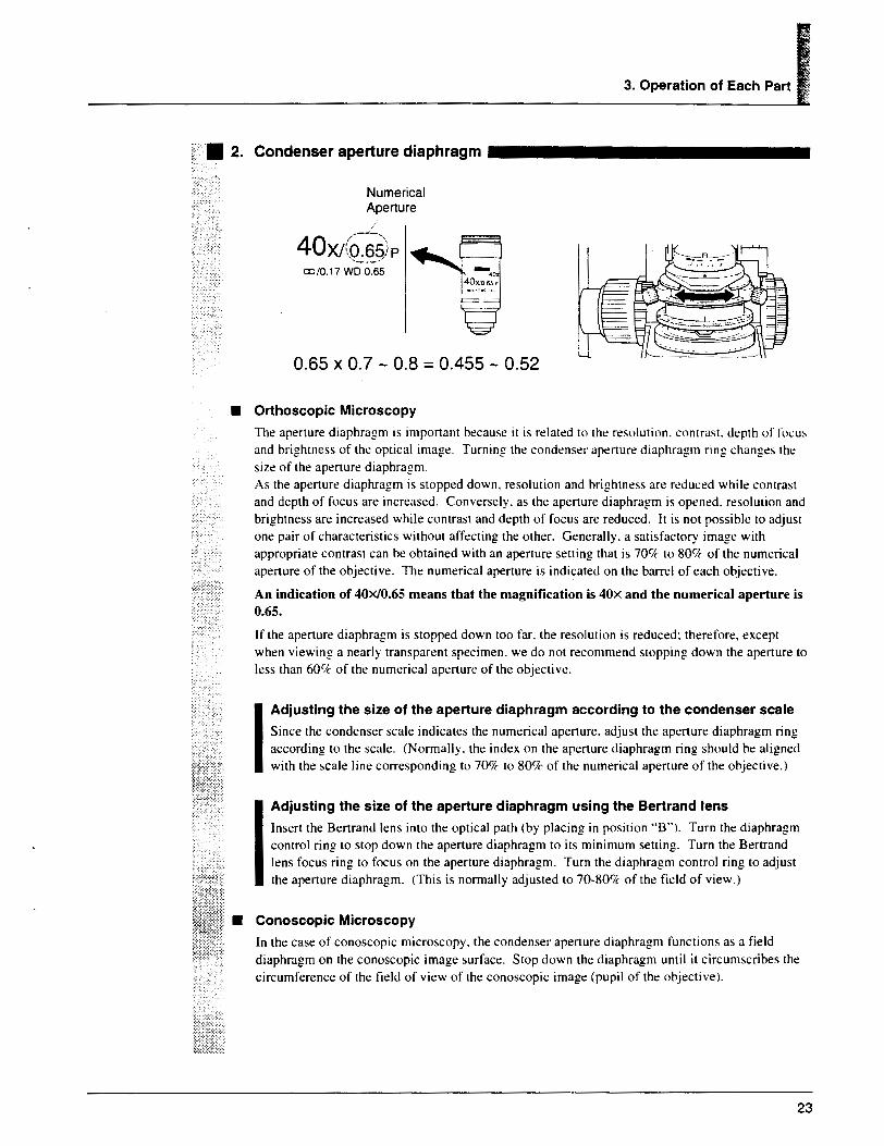
!; • 2. Condenser aperture diaphragm
Numerical Aperture I
40XJ(Q~~)p co/0.17 WD 0.65
0.65 x 0.7 - 0.8 = 0.455 - 0.52
• Orthoscopic Microscopy
3. Operation of Each Part I
The aperture diaphragm is important because it is related to the resolution. contrast. depth of focus and brightness of the optical image. Turning the condenser aperture diaphragm ring changes the size of the aperture diaphragm. As the aperture diaphragm is stopped down. resolution and brightness arc reduced while contrast and depth of focus are increased. Conversely. as the aperture diaphragm is opened. resolution and brightness are increased while contrast and depth of focus are reduced. It is not possible to adjust one pair of characteristics without affecting the other. Generally. a satisfactory image with appropriate contrast can be obtained with an aperture setting that is 70</1c to 809c of the numerical aperture of the objective. The numerical aperture is indicated on the barrel of each objective.
An indication of 40X/0.65 means that the magnification is 40x and the numerical aperture is 0.65.
If the aperture diaphragm is stopped down too far. the resolution is reduced: therefore, except when viewing a nearly transparent specimen. we do not recommend stopping down the aperture to less than 60'7c of the numerical aperture of the objective.
I Adjusting the size of the aperture diaphragm according to the condenser scale
Since the condenser scale indicates the numerical aperture. adjust the aperture diaphragm ring according to the scale. (Normally. the index on the aperture diaphragm ring should be aligned with the scale line corresponding to 70% to 80% of the numerical aperture of the objective.)
I Adjusting the size of the aperture diaphragm using the Bertrand lens
Insert the Bertrand lens into the optical path (by placing in position "B''). Turn the diaphragm control ring to stop down the aperture diaphragm to its minimum setting. Turn the Bertrand lens focus ring to focus on the aperture diaphragm. Turn the diaphragm control ring to adjust the aperture diaphragm. (This is normally adjusted to 70-80% of the field of view.)
• Conoscopic Microscopy
In the case of conoscopic microscopy. the condenser aperture diaphragm functions as a field diaphragm on the conoscopic image surface. Stop down the diaphragm until it circumscribes the circumference of the field of view of the conoscopic image (pupil of the objective).
23

24
, Top lens
"' - Swing-out knob
The rop lens of rhe swing-out condenser can be moved outside the optical path with the swing-out knob. During normal orthoscopic microscopy or conoscopic microscopy. the top lens is used while positioned in the oprical palh. During orthoscopic microscopy using a low-power objecrive of 4X or lower. swing out the top lens.
~~--';;: .
During measurement of retardation or evaluation by interference color. swing out the top lens (the condenser aperture diaphragm may be stopped down) and illuminate with light that is as parallel to the optical axis as possible.
II Field diaphragm
The field diaphragm restricts illumination to the area on the specimen being viewed. Turning the field diaphragm ring changes the size of the field diaphragm. For normal observation. the size of the diaphragm should be slightly larger than the boundary of the view field. If a broader area than necessary is illuminated. stray light will enter the view field, creating flaring and reducing the contrast of the optical image. The correct setting of the field diaphragm is especially important in photomicrography: generally, good results are obtained by stopping down the field diaphragm to just slightly larger than the area that will be reproduced on the film. i.e .. the size of the photo frame.
B Filters
Three filters are housed in the base of the microscope. A filter is inserted into the optical path by pressing in the filter insertion lever on the right side of the microscope. The filter is removed from the optical path by pressing the release lever down.
NCB11 (color balancing filter) For color balance adjustment and color photomicrography
ND32 (transmission rate: 3%) For brightness adjustment
NOB (transmission rate: 12.5%) For brightness adjustment
GIF (Optional) For retardation measurement and contrast adjustment (Place on the field lens.)
A diffuser is contained in the microscope. When removing the diffuser from the optical path, turn the diffuser insertion/removal screw as far as it will go (about 90°) in the counter-clockwise direction with a hexagonal screwdriver. When returning the diffuser to the optical path, tum the screw as far as it will go in the clockwise direction.

3. Operation of Each Part I m Auto-photo switch (for photomicrography)
The color temperature of the lamp varies according to the voltage. If the voltage is high. the color temperature of the lamp increases and the light becomes bluer. If the voltage is low. the color temperature of the lamp decreases and the light becomes redder. Therefore. to obtain the best color reproduction in color photomicrography. it is necessary for the lamp voltage to he kept constant. When using daylight-type color film. the standard setup is to use the color balancing filter (NCB 11 land set the lamp voltage to 9 V. The auto-photo switch is used to automatically set the standard lamp voltage (9 V l. If the images on color film shot with the auto-photo switch on are reddish or bluish. finely adjust the voltage with the auto-photo voltage selection switch. The center position of the 5-level slide switch is roughly 9 V. Sliding the switch forward increases the bluish tint of the light. while sliding the switch towards the hack increases the reddish tint of the light. Use commercially available color compensation filters (CC filters) if this adjustment does not resolve the problem.
m Oil-immersion operation (using an oil-immersion type of objective and condenser)
An objective marked "Oil" is an oil-immersion type. These objectives are used with the immersion oil applied between the specimen and the tip of the objective. The immersion oil is provided for the microscope.
Bubbles in the oil will adversely affect the viewing of the image. so he careful to prevent the formation of air bubbles. To check for air bubbles, remove the eyepieces. fully open the field and aperture diaphragms. and look at the exit pupil of the objective within the eyepiece tube. (The exit pupil will appear as a bright circle.) When it is difficult to see if there are any bubbles. mount a centering telescope (sold separately) on the eyepiece sleeve with an adapter (sold separately). Then. while turning the eyepiece on the centering telescope to change the focus. look through the centering telescope for air bubbles. If there are bubbles in the oil. remove them by one of the following methods:
• Turn the revolving nosepiece slightly, moving the oil-immersed objective back and forth once or twice.
• Add more oil. • Remove the oil and replace it with new oil.
Use as little oil as possible Uust enough to fill the space between the tip of the objective and the specimen). If too much oil is applied, the excess will flow onto the stage.
25

26
Any oil remaining on an oil-immersion type of objective or staining on the tip of a dry type of objective has a negative effect on viewing. After using oil. wipe all of it away and make sure that there is no oil on the tips of the other objectives.
Use petroleum benzine to wipe away immersion oil. Removing the oil and wiping with absolute alcohol (ethyl alcohol or methyl alcohol) will complete cleaning. If you cannot obtain petroleum benzine, use methyl alcohol. Note that methyl alcohol does not clean as well as petroleum benzine and it will be necessary to repeatedly wipe the surfaces (three or four times is usually sufficient to clean the lenses.)
&WARNING When using petroleum benzine or absolute alcohol. always follow the instructions provided by the manufacturer. Keep these flammable liquids away from fire or sparks.
II!] Orientation of polarizing plates (Polarizer and Analyzer)
; • Diascopic Observation
The dia-polarizer and analyzer coincide with the directions of the orientation plate on the top of the microscope base when the protractor scale is at ''O'' (the polarizer is in the X direction: P and the analyzer is in the Y direction: A), and are in the crossed Nicols position. The dark cross image as shown in the diagram can be observed at this time in the conoscopic observation.
It should be noted that the X direction is explained as that of the analyzer and Y direction as that of the polarizer in some commercially available technical manuals and reference books.
Polarizer scale: O
The dia-polarizer is attached to the bottom of the substage and can be rotated 360°. It can be removed from the bottom of the substage by pulling down as necessary. When re-attaching. align the positioning pin on the top of the polarizer with the groove in the bottom of the substage. Since the groove in the bottom of the substage is not visible when the condenser is attached to the substage, attach the polarizer after temporarily removing the condenser.
Analyzer Dark scale: O cross image

3. Operation of Each Part I The analyzer can be rotated hy first loosening the analyzer clamp screw i]J and then turning the rotation dial 2;. The angle of rotation can be read to 0.1 degrees over a range of 0-360 degrees with the vernier. The analyzer can be moved out of the optical path by pushing in the analyzer slider .1..,. Although the analyzer is designed. as standard. to be inserted from the right relative to the intermediate tube. it can also be inserted from the left. In this case. it may be somewhat difficult to read the angle of rotation since the readings on the scale. etc. are backward.
Since the intermediate tube contains a built-in depolarizer. it is not necessary to he concerned about the relationship between the orientation of the polarizing plate and photomicrographic devices.
• Episcopic Observation
- First click position - Second click position
In the case of performing episcopic polarizing microscopy. an episcopic polarizer is used in combination with the analyzer of the intermediate tube. Place a mirror or other isotropic specimen having a high reflectance on the stage and focus on that specimen. Set the analyzer scale to "ff' and replace the hollow slider of the epi-illuminator with the polarizer slider and insert the polarizer slider into the epi-illuminator. The empty hole will enter the optical path when the polarizer slider is pushed in until it clicks once.
= =t~-----' ..,,~..., ·: - .- ·~ '.: ,: ~J_CT~~ -- -' _ , Polarizer
~--it!'-- =:..-:~r?tation
The polarizer will enter the optical path when the polarizer slider is push in until it clicks twice. Turn the polarizer rotation ring of the polarizer slider until it reaches the crossed Nicols position in the same manner as during diascopic observation.
4 _::,.,,. _c:c. nng ~\\•' ·, -:__.---·
~ Polarizer slider
Direction of polarizer
I Lateral direction
Vertical direction
Be careful not to touch the polarizer rotation ring and change the orientation during observation. If this happens. the orientation must be reset.
27

28
m Focusing and centering the Bertrand lens
When changing the objectives. turn the Bertrand lens focus ring under the Bertrand lens turret of the intermediate tube and focus the Bertrand lens. Centering the Bertrand lens is performed with two centering screws. The centering procedure is the same as that for the condenser except that the condenser aperture diaphragm image is used instead of the field diaphragm image.
IE P-CL 1/4A. & tint plate
Bertrand lens centering screws
~,
The P-CL l/4A & tint plate has a hole in the center. By pushing it into the slot. the sensitive tint plate (530 nm) is brought into the optical path. Pulling it out brings the l/4A plate into the optical path. This plate is used for recognition of very weak birefringence and the determination of X and Y' of the specimen.
Ii] Centering the objectives
Before centering the objectives, focus on a specimen using the !Ox objective.
I Tools Used: Centering tools x 2 (provided) (when not in use, place them in the tool holder in the back of the microscope stand).
1 Bring an appropriate target such as granules that can be easily used as a marker in the specimen to the center of the crosshairs of the eyepiece.
2 Insert the centering tools into the centering screws on the nosepiece. 3 Rotate the stage about 180°. Move the objective using the centering tools so that the center
of the crosshairs moves by one-half the amount of movement of the target. 4 Next. move the specimen and bring the target to the center of the crosshairs. 5 Repeat this procedure several times. Carry out this centering procedure for each objective.
180° rotation
Target Middle point of the movement
The centering nosepiece has a DIN standard slot. This allows the use of a 1141.. & tint plate compatible with DIN standards.

3. Operation Of Each Part I llJ Circular graduated stage for polarizing microscope
• Stage rotation
Loosening the stage rotation clamp screw can rotate the stage. The angle of rotation can be read to 0.1 degrees from the two vernier scales.
• 45° click-stop
Turning the 45° click-stop lever towards the front until it stops causes the click-stop to move in 45° increments from the position where the lever was rotated. This makes it possible to move easily and accurately from the extinction position to the diagonal position. Turning the lever towards the back until it stops releases the clickstop device.
Stage rotation clamp screw
Release the click-stop device where the stage has dropped into a click position. If the clickstop device is released where the stage is not at this position. the first 45° increment will not be accurate the next time the click-stop device is operated.
m Use of optional accessories (Sold Separately)
P-CS Senarmont Compensator
The P-CS Senarmont compensator is used by inserting into the slot of the intermediate tube in place of the P-CL 1141. & tint plate. It can be used to measure retardation up to I A according to the following procedure.
It is normal to bring the top lens of the condenser into the optical path when observing at a magnification of !Ox or greater. Measuring the retardation or evaluating by interference color. however. stop down the condenser aperture diaphragm or swing out the top lens even for a magnification of !Ox or higher (with the aperture diaphragm fully opened). and illuminate with light that is as parallel to the optical axis as possible.
29

30
11 Determination of Extinction Position
Rotate the stage with the specimen under the crossed Nicols to find the direction where the part of the specimen to be measured appears darkest.
r Determination of Subtraction Position
Rotate the stage 45° from the extinction position to the diagonal position. Insert the P-CL l/4A. & tint plate into the optical path and confirm that the interference color of the section of the specimen to be measured changes toward the lower order side. If the interference color changes toward the higher order side. rotate the stage another 90°.
3 Measurement
Place the GIF filter on the field lens and replace the P-CL l/4A. & tint plate with the P-CS Senarmont compensator. Rotate the analyzer so that the section of the specimen to be measured becomes darkest. When the rotation angle of the analyzer at that time is taken to be theta (8) degrees. then retardation (R) (nm) is determined with the following formula:
e R =
180 /... (/...: wavelength used)
The value of A. when using the GIF filter is 546 nm.
• 2. P-CQ Quartz wedge
The P-CQ quartz wedge is used by inserting it into the slot of the intermediate tube in place of the P-CL l/4A. & tint plate. The quartz wedge is engraved with a scale and can be used for rough measurement of retardation in the range of I /...-6A..
It is normal to bring the top lens of the condenser into the optical path when observing at a magnification of IOX or greater. Measuring the retardation or evaluating by interference color. however. stop down the condenser aperture diaphragm or swing out the top lens even for a magnification of IOx or higher (with the aperture diaphragm fully opened). and illuminate with light that is as parallel to the optical axis as possible.
Determination of Extinction Position
Rotate the stage with the specimen under the crossed Nicols to find the direction where the part of the specimen to be measured appears darkest.
2 Determination of Subtraction Position
Rotate the stage 45° from the extinction position to the diagonal position (direction where the specimen appears brightest). Insert the P-CQ quartz wedge into the slot of the intermediate tube and confirm that the interference color of the section of the specimen to be measured changes toward the lower order side. If the interference color changes toward the higher order side. rotate the stage another 90°.

3 Measurement
Move the section of the specimen to be measured to the center of the crosshairs of the eyepiece. Next. slide the P-CQ quartz wedge along the slot and observe that the interference color sequentially changes. Stop sliding the quartz wedge where the dark stripe covers the section of the specimen to be measured. Reading the value from the quartz wedge scale at that time can make a rough measurement of retardation. Retardation can be measured even more accurately by using the P-CS Senarmont compensator in combination with the P-CQ quartz wedge.
• 3. Attachable Mechanical Stage
The attachable mechanical stage is installed by inserting the two pins on the bottom into the two pinholes on the stage surface. Tighten the clamp screw using the supplied hexagonal wrench.
3. Operation of Each Part I
Read the scale
- Clamp screw
31

32
Assembly
WARNING To prevent electrical shock or fire. turn off the power switch (flip it to the •·C'" side) during assembly.
CAUTION • Be careful not to pinch your hands or fingers when setting up th.: microscope. ---- • Viewing will be adversely affected if any of the lenses is scratched or has
fingerprints on it. Handle the lenses carefully during assembly. • This microscope is a precision optical instrument. Handle it cardully and do
t · not subject it to a strong physical shock. (The accuracy of the objectives in particular may be adversely affected by even a weak physical shock. l
Assemble each part in sequence as numbered in the diagram. (For details. refer tn pages 33 to 40.)
I Tools needed
• A hexagonal screwdrivers (provided) with the microscope • A hexagonal wrench (provided with the microscope) r-When not using. place these in the tool holder in the back of the microscope.
Installation location
1.3 mm 3mm
This product is a precision optical instrument and using or storing it under unsuitable conditions may damage it or may have an adverse effect on its accuracy. The following conditions should be kept in mind when selecting the installation location. • Avoid installing the microscope in a brightly lit location such as a room that receives direct
sunlight, or directly under room lights. The quality of the view through the microscope deteriorates if there is excessive ambient light.
• Install the microscope in a location that is free from dust or dirt. • Install the microscope on a flat surface with little vibration. • Install the microscope on a sturdy desk or table that is able to hear the weight of the
instrument. • Do not install the microscope in a warm. humid location (environmental temperature: 40°C or
higher and relative humidity: 60lff or more).

Photomicrographic vertical tube adapter
-Clamp the photom1crograph1c vertical tuber adapter (3 screws)
Eyepiece
(b........_~ Trinocular ~~eyepiece tube
Clamp the eyepiece tube I.I l Analyzer slider
~ = .J Intermediate Hexagonal screwdriver
4. Assembly I
a!~a.~=====:::i<oi:a ·--.... -~ b---= 9 tube - Hexagonal wrench
P-CS Senarmont compensator
P-CQ Quartz wedge [
P-CL 1/4i.. & tint plate J
I Centering revolving nosepiece
I Clamp the intermediate j tube
+~
c•mp•o..-o~ nosep1ece
- Centenng tools
Lamphouse cover
m 12VDC 100W halogen lamp
~
1 c1ampthe lampho.se i + Clamp the
lamphouse cover
L...-~~~--~..W.,..,...._..J--J1'",
~ ~Objective
Specimen E600 POL main unit clips
Circular graduated ----f stage for polarizing r microscope (including substage)
lilJ r~ C•mp <"rnb"'"
~ Clamp the condenser ~ (left side)
Swing-out condenser
Lamphouse
~ Power cord
33
34
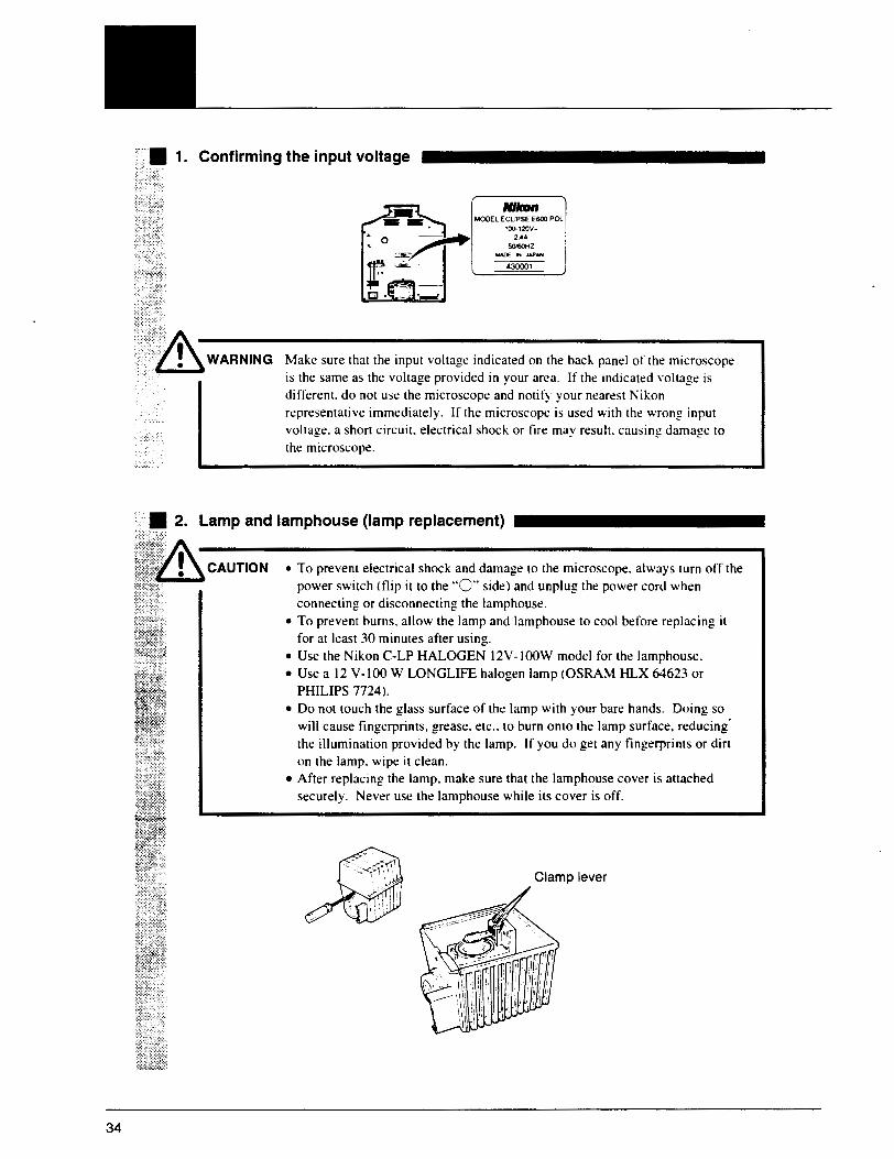
• 1. Confirming the input voltage
i::J. - ·-
ltllton MOOEL ECLIPSE E600 POL
100-120V-24A
SOISOHZ
430001
Make sure that the input voltage indicated on the back panel of the microscope is the same as the voltage provided in your area. If the indicated voltage is different. do not use the microscope and notify your nearest Nikon representative immediately. If the microscope is used with the wrong input voltage. a short circuit. electrical shock or fire may result. causing damage to the microscope.
• 2. Lamp and lamphouse (lamp replacement)
CAUTION • To prevent electrical shock and damage to the microscope. always turn off the ...._.._,. power switch (flip it to the "0" side) and unplug the power cord when
connecting or disconnecting the lamphouse. • To prevent burns. allow the lamp and lamphouse to cool before replacing it
for at least 30 minutes after using. • Use the Nikon C-LP HALOGEN 12V-IOOW model for the lamphouse. •Use a 12 V-100 W LONGLIFE halogen lamp (OSRAM HLX 64623 or
PHILIPS 7724 ). • Do not touch the glass surface of the lamp with your bare hands. Doing so
will cause fingerprints, grease. etc .. to burn onto the lamp surface, reducing. the illumination provided by the lamp. If you do get any fingerprints or dirt on the lamp. wipe it clean.
• After replacing the lamp. make sure that the lamphouse cover is attached securely. Never use the lamphouse while its cover is off.
Clamp lever
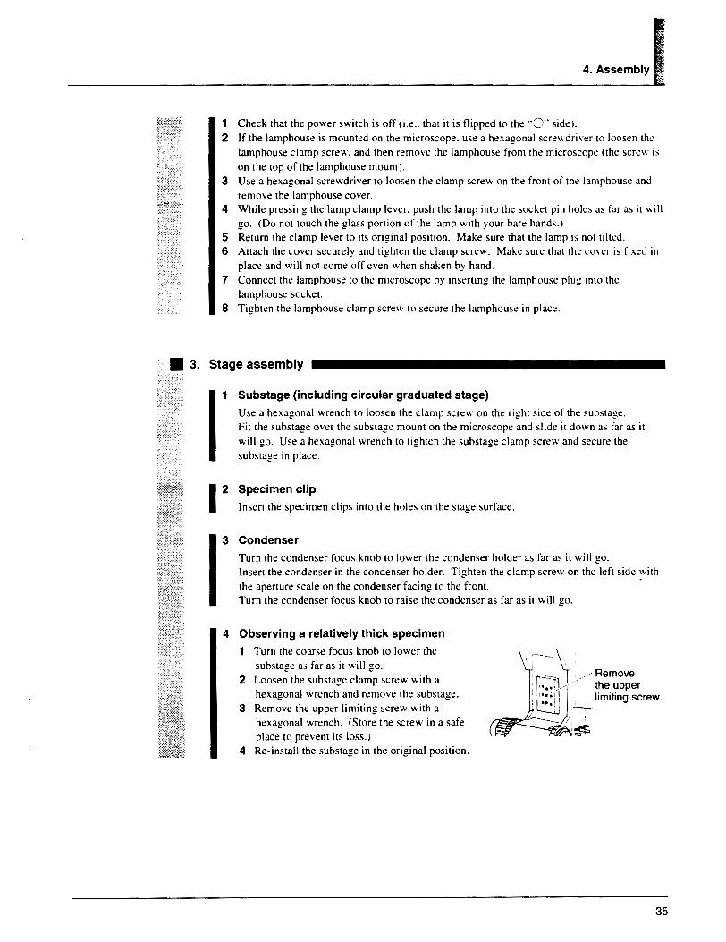
4. Assembly I 1 Check that the power switch is off (i.e .. that it is flipped to the OO::J .. side). 2 If the lamphouse is mounted on the microscope. use a hexagonal screwdriver to loosen the
lamphouse clamp screw. and then remove the lamphouse from the microscope (the screw is on the top of the lamphouse mount).
3 Use a hexagonal screwdriver to loosen the clamp screw on the front of the Jamphouse and remove the lamphouse cover.
4 While pressing the lamp clamp lever. push the lamp into the socket pin holes as far as it will go. (Do not touch the glass portion of the lamp with your bare hands.)
5 Return the clamp lever to its original position. Make sure that the lamp is not tilted. 6 Attach the cover securely and tighten the clamp screw. Make sure that the cm·er is fixed in
place and will not come off even when shaken by hand. 7 Connect the lamphouse to the microscope by inserting the lamphouse plug into the
lamphouse socket. 8 Tighten the lamphouse clamp screw to secure the lamphouse in place.
• 3. Stage assembly
Substage (including circular graduated stage)
Use a hexagonal wrench to loosen the clamp screw on the right side of the substage. Fit the substage over the substage mount on the microscope and slide it down as far as it will go. Use a hexagonal wrench to tighten the substage clamp screw and secure the substage in place.
12 Specimen clip
Insert the specimen clips into the holes on the stage surface.
Condenser
Turn the condenser focus knob to lower the condenser holder as far as it will go. r Insert the condenser in the condenser holder. Tighten the clamp screw on the left side with the aperture scale on the condenser facing to the front. Turn the condenser focus knob to raise the condenser as far as it will go.
4 Observing a relatively thick specimen
1 Turn the coarse focus knob to lower the substage as far as it will go.
2 Loosen the substage clamp screw with a hexagonal wrench and remove the substage.
3 Remove the upper limiting screw with a hexagonal wrench. (Store the screw in a safe place to prevent its loss.)
4 Re-install the substage in the original position.
/,,,,Remove the upper limiting screw.
35

36
r • 4. Revolving nosepiece assembly
1 Revolving nosepiece
Use a hexagonal screwdriver to loosen the revolving nosepiece clamp screw. Fit the revolving nosepiece into the revolving nosepiece mount on the microscope from the bottom and slide it toward the rear of the microscope as far as it will go. Tighten th.: clamp screw to secure the revolving nosepiece.
Note on removing the revolving nosepiece First. remove all the objectives. Lower the stage completely. and hold the n:volving nosepiece in your hand so that it does not fall when you remove it.
2 Objective
Lower the stage completely. Screw the objective into the revolving nosepiece so that the magnification increases when the nosepiece is rotated in the clockwise direction when looking down on the nosepiece from above.
When using the objective for episcopic observation When using the objective for episcopic observation (Mark: =10) with the Epi-illuminator. first screw in the objective attaching screw conversion adapter (M20.32 --+ ~2.5 and 25mm in thickness) to the revolving nosepiece and then screw in the objective to the adapter.
Note on removing objectives If there is a specimen on the stage. remove it first. Lower the stage comple!ely. and hold each objective in both hands so that they do not fall when you remove them.
• 5. Intermediate tube
Completely loosen the intermediate tube clamp screw on the microscope arm. Fit the circular dovetail of the intermediate tube into the circular dovetail groove of the microscope arm by tilting it at an angle. When fitting. insert the positioning pin on the intermediate tube in the receiving groove on the arm. Lock it in position by tightening the clamp screw.
Remove any looseness between the positioning pin and groove by pushing in the intermediate tube while rotating in the clockwise direction.

4. Assembly I ·• 6. Eyepiece tube assembly
1 Eyepiece Tube
Completely loosen the eyepiece tube clamp screw on the imermediate tube with the hexagonal screwdriveL Fit the circular dovetail of the eyepiece tube into the circular dovetail groove of the intermediate tube by tilting it at an angle. When filling. insert the positioning pin on the eyepiece tube in the receiving groove on the intem1ediate tube. Lock it in position by tightening the clamp screw.
Remove any looseness between the positioning pin and groove by pushing in the eyepiece tube while rotating in the clockwise direction.
2 Eyepieces
Attach eyepieces of the same magnification. Attach the eyepiece containing crosshairs on the right side so as to be viewed with the right eye. The sleeve has a positioning pins. Insert the eyepieces by aligning the grooves of the eyepiece with the positioning pins of the eyepiece tube sleeve. Insert the rubber eyegard (sold separately) so that they fit into the grooves around the outside of the eyepieces.
• 7. Power cord ·;, .
. ' Ii\ WARNING Use only the following power supply cord set. •For I00--120V area
UL Listed. detachable cord set. 3 conductor grounding type SVT. No. 18 AWG rated at 125V. 7A minimum. In case of using the extension cord. use only the power supply cord with the PE (protective earth) wire.
• For 220--240V area 3 pole power supply cord set. which must be approved according to EU/EN -standards. Class I equipment should be connected to PE (protective earth) terminal. In case of using the extension cord. use only the power supply cord with the PE (protective earth) wire.
Make sure to turn off the microscope power switch (flip it to the "0'' side) before connecting the power cord. Plug the cord into the socket of the AC input connector on the back of the microscope. Securely plug the other end of the cord into an AC outlet.
Covering the tapped holes with protective stickers
The four tapped holes on the upper surface of the microscope arm are for mounting accessories. such as Epi-fluon:scence attachment. etc. When not used, cover the tapped holes with the provided protective stickers.
37

38
· · • Installing separately sold accessories
Install photomicrographic equipment and other separately sold accessories by referring 10 the ·i.c~~:,;;, instruction manual for each accessory.
;.~ · • 8. Epi-illuminator assembly
In the case of performing episcopic polarizing microscopy. the optional accessory epi-illuminator is used by mounting between the E600 POL stand and the intermedia1e tube.
Assemble the epi-illuminator in the order of the numbers while referring to the diagram. Refer Ill the previous instructions for de1ails concerning lhe assembly procedures for 01her pans.
Tnnocular eyepiece tube
,-- Clamp the EpHllum1nator (4 bolts)
I I I Filter Lamphouse cover + Duma slider sloe~ D Filter m lntermediatetube ~ I l -
i + Clampthelamphouse ~12VDC100W
O.mmy ""~:m"""""'~::;"" o 0 io i -· ~" """ Epi-illuminator
E600POL
Clamp the lamp house Ept-lamphouse
1 Remove the eyepiece tube and 1he intermediale lube from the microscope s1and. 2 Mount the epi-illuminator nearly parallel to the microscope arm. 3 Tighten the epi-illuminator clamp screw on the right side of the arm with the hexagonal
screwdriver to Jock in position. 4 Screw in the four hexagonal head bolts supplied with the epi-illuminator to the screw holes
on the top of the epi-illuminator. and tighten the bolts using 1he hexagonal wrench. 5 Attach the lamp and lamphouse.

···:; ., ... -·x-·,
,,,_.-.. ··· ,.r·:.:i,; .,: ~ . ~=: ;:;_-:; ~~=
j.;;· ;;+=
~-:;~ "'.-.- ...
I
4. Assembly I • To prevent electrical shock and damage to the microscope. always turn off the
power switch (flip it to the "C" side) and unplug the power cord when connecting or disconnecting the lamphouse.
• To prevent burns. allow the lamp and lamphouse to cool before replacing it for at least 30 minutes after using.
• Use the Nikon LHS-HIOOP-2 HALOGEN 12V-100W model for the lamphouse.
• Use a 12 V-100 W LONGLIFE halogen lamp (OSRAM HLX 64623 or PHILIPS 7724 ).
• Do not touch the glass surface of the lamp with your bare hands. Doing so will cause fingerprints. grease. etc .. to burn onto the lamp surface. reducing the illumination provided by the lamp. If you do get any fingerprints or din on the lamp. wipe it clean.
• After replacing the lamp. make sure that the lamphouse cover is attached securely. Never use the lamphouse while its cover is off.
5·1 Check that the power switch is off (the switch is in the ··o·· position).
5-2 If the lamphouse is already mounted on the epi-illuminator. loosen the lamphouse clamp screw with the hexagonal screwdriver and remove the lamphouse JJ. (The clamp screw is on the right side.)
5-3 Loosen the lamphouse cover clamp screw with a coin or other tool llJ and remove the cover '31.
5-4 Securely insert the lamp into the pinholes of the socket [[] until it does not go in any farther while pressing down on the lamp clamp lever ~-
Do not touch the glass portion of the lamp with your bare hands.
5·5 Return the lamp clamp lever to its original position.
Be careful so that the lamp is not installed tilting to one side.
5-6 Securely close the lamphouse cover and tighten the clamp screw.
5-7 After completely loosening the lamphouse clamp screw. securely plug the lamphouse plug into the socket of the lamphouse mount and then tighten the lamphouse clamp screw.
39

40
4.anJ 6 Connect the lamphouse cord to the epi-illumintor connector on the back of the microscope. 7 Insert the hollow sliders all the way into the front and right sides of the epi-illuminaior so
that the open hole enters the optical path. 8 Attachment of Filter Slider (Various Filters)
8-1 Remove the filter slider from the epi-illuminator. 8-2 Pull out and remove the locking plate. 8-3 Insert the desired filter.
The filter slider contains two filters. 8-4 Insert and attach the locking plate. 8-5 Affix the label at the same position as the filter. 8-6 Attach the filter slider to the epi-illuminator.
9 Mount !he intermediate tube on the epi-illuminator. 10 Mour .. 1he eyepiece tube on the intermediate tube.
-8-5
The eyepiece tube. intermediate tube and epi-illuminator are provided wi1h positioning pins. while the intermediate tube. epi-illuminaior and microscope arm are provided wirh grooves for engaging with those pins. Remove any looseness between the pins and grooves that occurs during assembly by pushing in on the component provided with the pin while turning in the clockwise direction.

Troubleshooting Tables
Improper use of the microscope may adversely affect the performance even if it is not damaged. If any of the problems listed in the table below occur. follow the countermeasures.
D Viewing and control systems
Problem Cause Countermeasure
The optical path seleccion lever on the eyepiece cube is in an intermediace
Sec the opcical pach seleccion leYer w position. I OO'K of the binocular eyepiece.
The opcical path seleccion lever on the (p.201 eyepiece tube is not sec IO I 00'7c of the binocular eyepiece.
The diffuser is in an intermediace Insert and remove correccly. lp.2~)
position.
The revolving nosepiece has not been Install the revolving nosepiece installed properly. correctly. (p.36)
The revolving nosepiece has not been Tum the revolving nosepiece until it rotated until ii has clicked into place. clicks imo place. (Place the objeccive in (The objeccive is not in the optical path.) the optical path. l (p.12)
Vignetting or uneven Position the condenser so that the image brightness in the view field; The condenser is 100 low. of the field diaphragm forms properly on the entire view field cannot che specimen. (p.22) be seen.
The condenser is not centered. Center the condenser. (p.22)
The condenser is not installed properly. I nscall the condenser correct I y. (p.35)
The filters are not switched fully into Switch !he filters correctly. (p.241
position.
The field diaphragm is s!Opped down Open the diaphragm to a suitable size. (00 far. (p.24)
The lamp is not installed properly. Install the lamp correctly. (p.34)
The Bertrand lens is in the optical path. Move out of the optical path.
The !Op lens of !he swing-ouc condenser Correctly push in all the way.
is not positioned properly.
The P-CL. P-CS or P-CQ plate is not Position correctly.
inserted correct! y.
Position the condenser so that the image The condenser is too low. of the field diaphragm forms properly
on the specimen. (p.22)
Dirt or dust in the view The aperture diaphragm is stopped down Open the diaphragm to a suitable size.
field. too far. (p.23)
There is dirt or dust on the lens. Clean the components. (p.45)
condenser. eyepiece. filter or specimen.
41

Problem Cause Countermeasure
The aperture diaphragm is stopped down Open the diaphragm to a suitable sin:. too far. lp.231
Position the condenser so that the image The condenser is too low. of the field diaphragm forms proper!~ on
the specimen. \p.22l
The cover glass is too thick. Use the specified type of cover glass
There is no cover glass. (thickness: 0.17 mm).
There is no oil on the tip of an oil-immersion type of objective.
Apply Nikon immersion oil. \p.2.'il The specified immersion oil is not being used.
There are bubbles in th.:- immersion oil. Remo\'e the buhhl.:-~. lp.251
Viewing is poor (too much There is immersion oil on the tip of a dry I
or too little contrast, poor type of objective. Clean the components. lp.2.'i!
resolution). The compensation ring on an objective fitted with a compensation ring has not
Adjust the compensation ring according
been adjusted. to the cover glass.
There is dirt or dust on the lens. Clean the components. (p.4.'i)
condenser. objective or specimen.
A specimen with a cover glass is being Use an objective that allows observation
observed with an objective for observing of specimens with a cover glass.
specimens without a cover glass.
A specimen without a cover glass is being Use an objective for observing specimens observed with an objective for observing without a cover glass. specimens covered with a cover glass. Mark on
the objective oo/O.J7: For observing a specimen with
a cover glass oo/O: For observing a specimen
without a cover glass oo/-: For observing either specimen
with or without a cover glass
The revolving nosepiece has not been Install the revolving nosepiece correctly. installed properly. (p.36)
Uneven focus. The revolving nosepiece has not been Tum the revolving nosepiece until it rotated until it clicks into place. clicks into place. lp.12)
The specimen is not secured in place on Install the specimen properly in the the stage. specimen clips on the stage.
The revolving nosepiece ha~ not been Install the revolving nosepiece correctly. installed properly. (p.36)
The revolving nosepiece has not been Tum the revolving nosepiece until it Image flows. rotated until it clicks into place. clicks into place. (p.12)
The specimen is not secured in place on Install the specimen properly in the the stage. specimen clips on the stage.
The condenser is not centered. Center the condenser. lp.22)
42

5. Troubleshooting Tables I Problem Cause Countermeasure !
An NCB 11 filter is not being: used. Use the NCB 11 filter. (p.2~1
The image is yellowish. The lamp voltage is too low.
Push auto-photo switch and then adjust The image is too bright. The lamp voltage is too high. the brightness through the ND filter
combination. l p.2~ and 25) The lamp voltage is too low.
Inadequate illumination The aperture diaphragm is stopped down Open the diaphragm to a suitable size. (also check the electrical too far. \p.2>l system problems and
Position the condenser so that the image countermeasures). The condenser is too low. of the field diaphragm fonns properly on
the specimen. (p.221
The specimen is placed upside-down. Set the specimen on the stage with the
Focusing is not possible cover glass facing up.
with high-power objectives. Use the specified type of cover glas~ The cover glass is too thick.
uhickness: 0.17 mml
The specimen is placed upside-down. Set the specimen on the stage with the
The objective strikes the cover glass facing up.
specimen when changing Use the specified type of cover glass from a low-power objective The cover glass is too thick.
\thickness: 0.17 mml. to a high-power objective.
The diopter setting has not been adjusted. Adjust the diopter setting. (p.21)
The difference in focus is large when the objective is The diopter setting has not been adjusted. Adjust the diopter setting. (p.21) changed.
When viewing through The interpupillary distance has not been Adjust the interpupillary distance. (p.21)
the binocular eyepiece, adjusted.
the image does not resolve into a single image. The diopter setting has not been adjusted. Adjust the diopter setting. (p.21)
The interpupillary distance has not been Adjust the interpupillary distance. (p.21)
Eye strain develops while adjusted.
viewing. The diopter setting has not been adjusted. Adjust the diopter setting. (p.21)
The brightness level is not suitable. Adjust the brightness through the ND filter combination. (p.24)
43

5. Troubleshooting Tables I El Electrical system
Problem Cause Countermeasure
The power is not being supplied. Plug the power cord into an outlet. \p.37)
The power cord is not connected to the Connect the power cord. ip.:m The lamp does not light microscope.
when the power switch is turned on. The lamp has not been installed. Install the lamp. \p.34l
The lamp is burned out. Replace the lamp. !p.34)
The specified lamp is not being used. Use the specified lamp trefer to the electrical specifications on p.46 l. lp .. ~4l
The lamp is near the end of its life. Replace the lamp. lp.34l
The power cord is not connected securely. Secure the connection. (p .. ~7l
The lamp flickers; The lamp is not plugged into its socket Insert the lamp securely into its ~ocket.
the brightness is unstable. securely. (p.34)
The lamphouse is not connected to the I Connect the lamphouse securely. (p.34) microscope securely.
44

Care and Maintenance
D Lens cleaning
Do not let dust. fingerprints. etc. get on the lenses. Dirt on the lenses. filters. etc. will adversely affect the view of the image. If any of the lenses gets dirty. clean it as descrihed hdow.
• Either brush away dust with a soft brush. or gently wipe away with gauze. • To remove fingerprints or grease. use a piece of soft. clean cotton cloth. lens tissue. or gauze
moistened with absolute alcohol (ethyl alcohol or methyl alcohol). • Use petroleum benzine to clean off immersion oil (p. ::!5). • Do not wipe the entrance lens on the eyepiece tube with petroleum benzine. • Absolute alcohol and petroleum henzine are both highly flammahle. Be careful when
handling them. when around open flames. or when turning the power switch on and off. • Follow the instructions provided by the manufacturer when using ahsolute alcohol and
petroleum benzine.
El Cleaning painted components
Do not use organic solvents such as alcohol. ether or paint thinner on painted components. plastic components or printed components. Doing so could result in discoloration or in peeling of the printed characters. For persistent dirt. dampen a piece of gauze with neutral detergent and wipe lightly.
IJ Storage
Store the microscope in a dry place where mofd is not likely to form. Store the objectives and eyepieces in a desiccator or similar container with a drying agent. Put the vinyl cover over the microscope after use to protect it from dust. Before putting on the vinyl cover. turn off the microscope power (flip the switch to the" " position), and wait until the lamphouse has cooled.
IJ Regular inspection
Regular inspection of this microscope is recommended to maintain peak performance. Contact your nearest Nikon representative for details about n:gular inspection.
45

46
Specifications and Standards
- • 1. Model Name:
• 2. Focusing Mechanism:
• 3. Stage:
• 4. Revolving Nosepiece:
• 5. Illumination:
~. • 6. Input Power Supply ' Voltage:
• 7. Protection Class:
8. Operating Environmental Conditions:
ECLIPSE E600 POL (microscope main body)
• Fine focus knob scale: 1 step equals I µm
• Amount of movement of fine focus knob: One turn moves the stage up or down by 0.1 mm
• Amount of movement of coarse focus knob: One turn moves the stage up or down by about 12 mm
• Range of stage vertical motion: 2 mm up and 23 mm down from the refrrence (focused) position
• Circular graduated stage with two verniers • Provided with a rotation mechanism with a clamp • Provided with a 45° click-stop • Provided with two specimen clips
•Quintuple • Provided with an objective centering mechanism
• Internal Koehler-type diascopic illumination optics • Provided with a PHOTO switch (5-level fine adjustment
selector) • Lamp rating: I 2V DC. I OOW halogen lamp
(OSRAM HLX64623 or PHILIPS 7724)
• AC I 00- l 20V ± I Olk 50/60Hz Current consumption: Internal fuse rating:
• AC 230V ± 10% 50/60Hz Current consumption: Internal fuse rating:
Class I
o to +40°C
2.4A or less 125V, 5A
l.2A or less 250V. T3.15A
• Temperature: •Humidity: • Altitude:
85% RH max., non-condensing 2000m max.
• Pollution: Degree 2 • Installation: Category II • Indoor use only

Conforming Standards: • Product with AC 100-120V
• Product with AC 230V
7. Specttications and Standards ' '~.;:
• UL Listed product • FCC !SB Class A satisfied This equipment has been tested and found to comply with the limits for a Class A digital device pursuant to Part IS of the FCC Rules. These limits are designed to provide reasonabk protections against harmful interference when the equipment is operated in a commercial environment. This equipment generates. uses. and can radiate radio frequency energy and if not installed and used in accordance with the instruction manual. may cause harmful interference to radio communications. Operation of this equipment in a residential area is likd: to cause harmful interference in which the user will be required tt> correct the interference at this own expense.
This Class A digital apparatus meets all requirements of the Canadian Interference-Causing Equipment Regulations. Cet appareil numt!rique de la Classe A respecte toutes Jes exigences du Reglement sur le materiel brouilleur du Canada.
• GS approved product • EU Low Voltage Directive satisfied • EU EMC Directive satisfied
47

ISO 9001 Certified
1509001 --·
MKON CORPORATION
--Division Yokohama Plant
NIKON CORPORATION 9-16. Ohi 3-chame. Sh•nagawa-ku. Tokyo 140-8505. Japan Tel: +81-3-3773-812118122 Fax: +81-3-3773-8115
NIKON INC. Instrument Group
1300 Walt Whitman Roac:. Melville. NY 11747-3064. U.S.A. Tel: +1-516-547-8500 Fax: +1-516-547-0306
NIKON EUROPE B.V. SchiphOlweg 321. P.O. Box 222. 1170 AE Badhoevedorp, The Netherlands Tel: +31-20-44-96-222 Fax: +31-20-44-96-298
This instruction manual •S prin!ed on lhe recycled paper. M2 I 5 E 98.8.VFI