eco-tech plus - fiscally chic · eco-tech ® plus gas convection ... the information contained in...
TRANSCRIPT

ECO-TECH® PLUSGAS CONVECTION STEAMER
INSTALLATION - OPERATION - MAINTENANCE
Telephone: (802) 658-6600 Fax: (802)864-0183www.marketforge.com PN 14-0270 Rev C (1/17)
© 2017 - Market Forge
MODEL
�ETP-10G

Your Service Agency’s Address:Model
Serial number
Steamer installed by
Installation checked by
TABLE OF CONTENTS
INSTALLATIONService Connections . . . . . . . . . . . . . . . . . . . . . . . . . . . . . . . . . . . . . . . . . . . . . 2Introduction . . . . . . . . . . . . . . . . . . . . . . . . . . . . . . . . . . . . . . . . . . . . . . . . . . . . . . 3Installation. . . . . . . . . . . . . . . . . . . . . . . . . . . . . . . . . . . . . . . . . . . . . . . . . . . . . . . 4Water Conditioning . . . . . . . . . . . . . . . . . . . . . . . . . . . . . . . . . . . . . . . . . . . . . . . 7Filter Change Procedure . . . . . . . . . . . . . . . . . . . . . . . . . . . . . . . . . . . . . . . . . . 8Performance Check . . . . . . . . . . . . . . . . . . . . . . . . . . . . . . . . . . . . . . . . . . . . . . 9
OPERATIONOperating Instructions . . . . . . . . . . . . . . . . . . . . . . . . . . . . . . . . . . . . . . . . . . . 10
Lighting . . . . . . . . . . . . . . . . . . . . . . . . . . . . . . . . . . . . . . . . . . . . . . . . . . . . 10Cooking . . . . . . . . . . . . . . . . . . . . . . . . . . . . . . . . . . . . . . . . . . . . . . . . . . . . 10Cleaning . . . . . . . . . . . . . . . . . . . . . . . . . . . . . . . . . . . . . . . . . . . . . . . . . . . 11Drainage . . . . . . . . . . . . . . . . . . . . . . . . . . . . . . . . . . . . . . . . . . . . . . . . . . . 11
Control Panel . . . . . . . . . . . . . . . . . . . . . . . . . . . . . . . . . . . . . . . . . . . . . . . . . . . 12Test Kitchen Bulletin . . . . . . . . . . . . . . . . . . . . . . . . . . . . . . . . . . . . . . . . . . . . . 13Cooking Guide . . . . . . . . . . . . . . . . . . . . . . . . . . . . . . . . . . . . . . . . . . . . . . . . . . 15
MAINTENANCECleaning & Preventative Maintenance. . . . . . . . . . . . . . . . . . . . . . . . . . . . . 18
Cleaning . . . . . . . . . . . . . . . . . . . . . . . . . . . . . . . . . . . . . . . . . . . . . . . . . . . 18Deliming . . . . . . . . . . . . . . . . . . . . . . . . . . . . . . . . . . . . . . . . . . . . . . . . . . . . 19
IMPORTANT WARNING: Improper installation, ad-justment, alternation, service or main-tenance can cause property damage, injury or death. Read the installation, operation and maintenance instruc-tions thoroughly before installing or servicing this equipment.
INSTRUCTIONS TO BE FOLLOWED IN THE EVENT THE USER SMELLS GAS MUST BE POSTED IN A PROMINENT LOCATION. This information may be ob-tained by contacting your local gas sup-plier.
FOR YOUR SAFETY
Do not store or use gasoline or other flammable vapors or liquids in the vicin-ity of this or any other appliance.
Do not attempt to operate this unit in the event of power failure.
Adequate clearances must be maintained for safe and proper operation.
The appliance area must be kept free and clear of combustibles.
Do not obstruct the flow of combustion and ventilation air.
The information contained in this manual is important for the proper installation, use, and maintenance of this steamer. Adherence to these procedures and in-structions will result in years of trouble-free service. Please read this manual carefully and retain it for future reference.
ERRORS: Descriptive, typographic or pictorial errors are subject to correction. Specifications are subject to change without notice.
2INSTALLATION
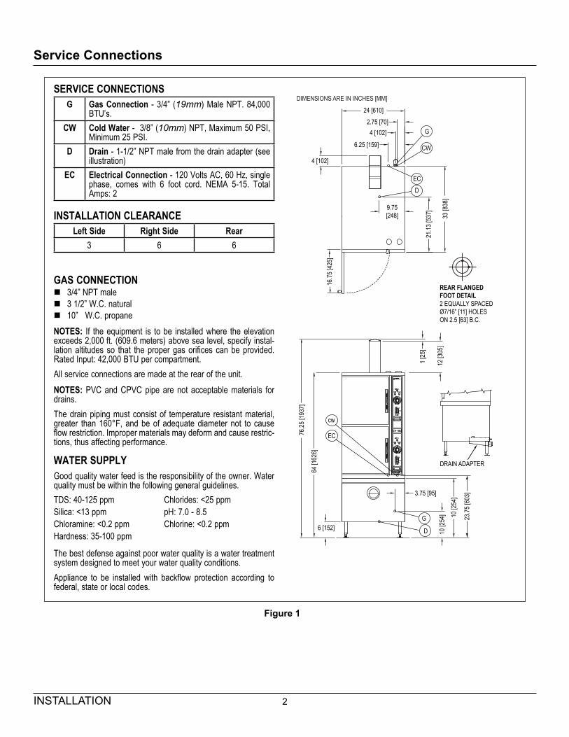
Service Connections
SERVICE CONNECTIONSG Gas Connection - 3/4” (19mm) Male NPT. 84,000
BTU’s.CW Cold Water - 3/8” (10mm) NPT, Maximum 50 PSI,
Minimum 25 PSI.D Drain - 1-1/2” NPT male from the drain adapter (see
illustration)EC Electrical Connection - 120 Volts AC, 60 Hz, single
phase, comes with 6 foot cord. NEMA 5-15. Total Amps: 2
INSTALLATION CLEARANCELeft Side Right Side Rear
3 6 6
GAS CONNECTION � 3/4” NPT male � 3 1/2” W.C. natural � 10” W.C. propane
NOTES: If the equipment is to be installed where the elevation exceeds 2,000 ft. (609.6 meters) above sea level, specify instal-lation altitudes so that the proper gas orifices can be provided. Rated Input: 42,000 BTU per compartment.All service connections are made at the rear of the unit.NOTES: PVC and CPVC pipe are not acceptable materials for drains.The drain piping must consist of temperature resistant material, greater than 160°F, and be of adequate diameter not to cause flow restriction. Improper materials may deform and cause restric-tions, thus affecting performance.
WATER SUPPLYGood quality water feed is the responsibility of the owner. Water quality must be within the following general guidelines.TDS: 40-125 ppm Chlorides: <25 ppmSilica: <13 ppm pH: 7.0 - 8.5Chloramine: <0.2 ppm Chlorine: <0.2 ppmHardness: 35-100 ppm
The best defense against poor water quality is a water treatment system designed to meet your water quality conditions.Appliance to be installed with backflow protection according to federal, state or local codes.
24 [610]2.75 [70]4 [102]
6.25 [159]
G
CW
ECD
4 [102]
9.75[248]
21.13
[537
]
33 [8
38]
16.75
[425
]
1 [25
]
12 [3
05]
cw
EC76.25
[193
7]
64 [1
626]
6 [152]G
D
3.75 [95]
10 [2
54]
23.75
[603
]
10 [2
54]
REAR FLANGEDFOOT DETAIL2 EQUALLY SPACEDØ7/16” [11] HOLESON 2.5 [63] B.C.
DIMENSIONS ARE IN INCHES [MM]
DRAIN ADAPTER
Figure 1
3 INSTALLATION
Introduction
DESCRIPTIONThe ETP-10G is a gas fired pressureless steam cooker. The cooking compartments are equipped with a three-piece door with inner gasket plate isolated from the exte-rior surface. Door latch operates by slam action for posi-tive sealing of the door. Operating controls are displayed on a front-mounted panel and include indicator lights for ignition, ready and cooking modes, a timer to set cook times and a selectable hold cycle to keep food warm once cooked, a temperature display to monitor cavity tempera-ture, and an illuminated ON/OFF/DELIME switch. Each stainless steel steam generator operates “0” PSI (0 kg/cm2) and is rated at 42,000 BTU.
BASIC FUNCTIONINGThe cooker is ready for operation when the READY light comes on.At the end of the set interval, timer contacts switch to shut off the cooking operation and sound a signal buzzer. The buzzer is silenced by returning the timer dial to the OFF position. In the ‘HOLD’ mode, the cooker will maintain a safe food holding temperature at or above 150°F. Steam and liquids from each cooking cavity pass through a removable drain screen in the cavity and into the tem-pering tank. When the appliance is shut off, the steam generators will also drain into the tempering tank. The tempering tank condenses any residual steam and tem-pers the waste water to 140°F or less.
4INSTALLATION
Installation
SETTING IN PLACEThe location of installation must be under an exhaust hood, which will remove water vapour emitted when the cooker door is opened, and exhaust combustion fumes. Level the unit in final location by turning the adjustable feet. Using the cabinet top as a reference, obtain level adjustment left-to-right and front-to-back.
MECHANICAL CONNECTIONSAll electrical and plumbing connections are located on the rear panel of the unit. See ‘SERVICE CONNECTIONS for location of mechanical connections.
INSTALLATION CODES AND STANDARDSInstallation must conform with local codes, or in absence of local codes, with the National Fuel Gas Code - ANSI Z223.1/NFPA 54, or the Natural Gas and Propane Instal-lation Code, CSA B149.1 as applicable.1. The appliance and its individual shut off valve must
be disconnected from the gas supply piping system during any pressure testing of that system at pres-sures in excess of 1/2 PSI (0.035 kg/cm2).
2. The appliance must be isolated from the gas supply piping system by closing its individual manual shut off valve during any pressure testing of the gas supply piping system at test pressures equal to or greater than 1/2 PSI (0.035 kg/cm2).
Electrical grounding must be provided in accordance with local codes, or in the absence of local codes, with the National Electrical Code ANSI/NFPA 70, or the Canadian Electrical Code, CSA C22.2 as applicable.Ventilation must be provided in accordance with local codes, or in the absence of local codes, with ANSI/NFPA 96 Standard for Ventilation and Fire Protection of Com-mercial Cooking Operations.
WARNINGElectrical grounding instructions - Units come equipped with a three-prong (grounding) plug for your protection against shock hazard and should be plugged directly into a properly grounded three-prong receptacle. Do not cut or remove the grounding prong from this plug. (120 VOLT UNITS ONLY)
WIRING DIAGRAM FOR APPLIANCE IS LOCATED ON RIGHT HAND SIDE PANEL OF THE COOKER CABINET.
EXHAUST FANS AND CANOPIESCanopies are set over ranges, ovens, kettles, etc., for ventilation purposes. It is recommended that a canopy extend 6” past the appliance and be located 6’ 6” from the floor. Filters should be installed at an angle of 45 degrees or more with the horizontal. This position prevents drip-ping of grease and facilitates collecting the run-off grease in a drip pan, usually installed with the filter. A strong exhaust fan tends to create a vacuum in the room and may interfere with burner performance or may extinguish pilot flames. Makeup air openings approximately equal to the fan area will relieve such vacuum. In case of unsat-isfactory performance on any appliance, check with the exhaust fan in the “OFF” position.
WALL EXHAUST FANExhaust fans should be installed at least two feet above the vent opening at the top of the unit.
CLEARANCESAdequate clearance must be provided in aisle and at the side and back. Adequate clearances for air openings into the combustion chamber must be provided, as well as for serviceability. Minimum clearance from combustible and noncombustible construction, 3” on left side, 8” on right side and 6” from back.
WARNINGThese procedures must be followed by quali-fied personnel or warranty will be voided. An open gap floor drain is required immediately below the appliance drain.

5 INSTALLATION
Installation
To Install 1. Uncrate carefully. Report any freight damage to the
freight company immediately.
2. Set the unit in place. Be certain to maintain the mini-mum clearances from combustibles and non-com-bustibles.
3. For an appliance supplied with legs, level the ap-pliance using a spirit level. Four flanged adjustable feet are provided for permanent anchoring to the floor. With the unit in location, mark hole locations on the floor through the anchoring holes. Remove the steamer and drill holes at marked locations on the floor. Insert proper anchoring devices.
4. Set steamer back in proper position.
5. Install bolts through anchoring holes and into anchors to secure the steamer to the floor. Seal bolts and flanged feet with Silastic™ or equivalent silicone seal-ant.
6. After the drain is connected, check for level by pour-ing water onto the floor of the compartment. All water should drain through the opening at the back of the compartment cavity.
WARNINGFor an appliance equipped with casters, the installation shall be made with a connector that complies with the Standard for Con-nectors for Moveable Gas Appliances, ANSI Z21.69/CSA 6.16 and a quick-disconnect device that complies with the Standard for Quick-Disconnect Devices for use with Gas Fuel, ANSI Z21.41/CSA 6.9; adequate means must be provided to limit the movement of the appliance without depending on the connector and the quick-disconnect device or its associ-ated piping to limit the appliance movement: the location where restraining means may be attached is directly above the gas supply inlet pipe on the rear of the appliance. The water inlet connections must also be installed with a flexible water supply line, a quick disconnect and strain relief.
GAS CONNECTION1. The Serial and Rating Plate on the unit indicates the
type of gas your unit is equipped to burn. DO NOT connect to any other gas type.
2. A 3/4” NPT line is provided at rear for the connection. Each compartment is equipped with an internal pres-sure regulator which is set at 3.5” W.C. manifold pres-sure for natural gas and 10” W.C. for propane gas. Use C” pipe tap on the burner manifold for checking pressure.
An adequate gas supply is imperative. Undersized or low pressure lines will restrict the volume of gas required for satisfactory performance. A steady supply pressure, be-tween 6” W.C. and 14” W.C. for natural gas and 11” W.C. and 14” W.C. for propane gas is recommended. With all units operating simultaneously, the manifold pressure on all units should not show any appreciable drop. Fluctua-tions of more that 25% on natural gas and 10% on pro-pane gas will create problems, affecting burner operation. Contact your gas company for correct supply line sizes.Purge the supply line to clean out any dust, dirt or other foreign matter before connecting the line to the unit. Use pipe joint compound which is suitable for use with LP on all threaded connections. Test pipe connections thoroughly for gas leaks.
WARNINGNever use an open flame to check for gas leaks. Check all connections for leaks using soapy water before use.
NOTICEIf this equipment is being installed at over 2,000 feet altitude and was not so specified on order, contact service department. Failure to install with proper orifice sizing may void the warranty.
ELECTRICAL CONNECTION 120 VAC-60 Hz - Single PhaseUnits with this electrical rating are factory supplied with a three-wire cord and three-prong plug which fits any stan-dard 120V, three-prong grounded receptacle. A separate 15 amp supply is needed for each unit.

6INSTALLATION
Installation
PLUMBING CONNECTIONS
NOTICEEquipment not installed in accordance to these guidelines may void the warranty.
WARNINGPlumbing connections must comply with ap-plicable Sanitary, Safety and Plumbing Codes.
WARNINGAn obstructed drain can cause personal injury or property damage.
One Cold Water line is required. Connect water supply line to the 3/8” NPT Female connection at the rear of the steamer.
DRAIN CONNECTIONS
WARNINGDirectly plumbing a drain line to the tempering tank may cause personal injury or damage to the appliance. Not using the supplied drain adapter will void your warranty.If this equipment is being installed over an open floor drain, the Drain Adapter is not required.
WARNINGPVC OR CPVC are not acceptable materials for drains.The drain piping must consist of temperature resistant material, greater than 160°F, and be of adequate diameter not to cause flow restriction. Improper materials may deform and cause restrictions, thus affecting perfor-mance.
Installing the Drain AdapterFrom the rear of the unit, position the drain adapter hooks through the slots in the floor of the cabinet to and align with the holes at the rear and fasten in place with provided screws.When making the drain connection to the 1½” NPT male thread of the drain adapter, use a pipe wrench to firmly support the drain adapter nipple to prevent damage to the assembly.
DRAIN ADAPTER
HOOKS SCREWS
Figure 2
7 INSTALLATION
Water Conditioning
Untreated water contains scale producing minerals which can precipitate onto the surfaces in the steam genera-tor. Due to the temperatures in the steam generator, the minerals can bake onto the surfaces and components. This can result in early component failure and reduced product life. Water level probes become coated with scale. Scale may bridge across the probe insulator from the metal extension which senses the water level in the steam generator shell. Once this scale becomes wet, the water level control is unable to maintain the proper water level in the steam generator.STRAINERS and FILTERS will NOT treat equipment for scale reduction. This equipment is furnished with an CUNO® Commercial Series water filtration system. An ini-tial flushing procedure for the filter system must be per-formed before using this equipment.
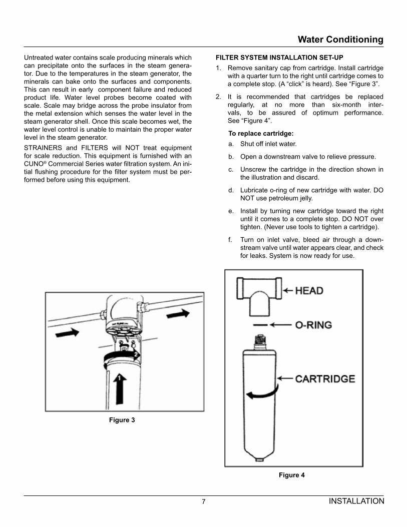
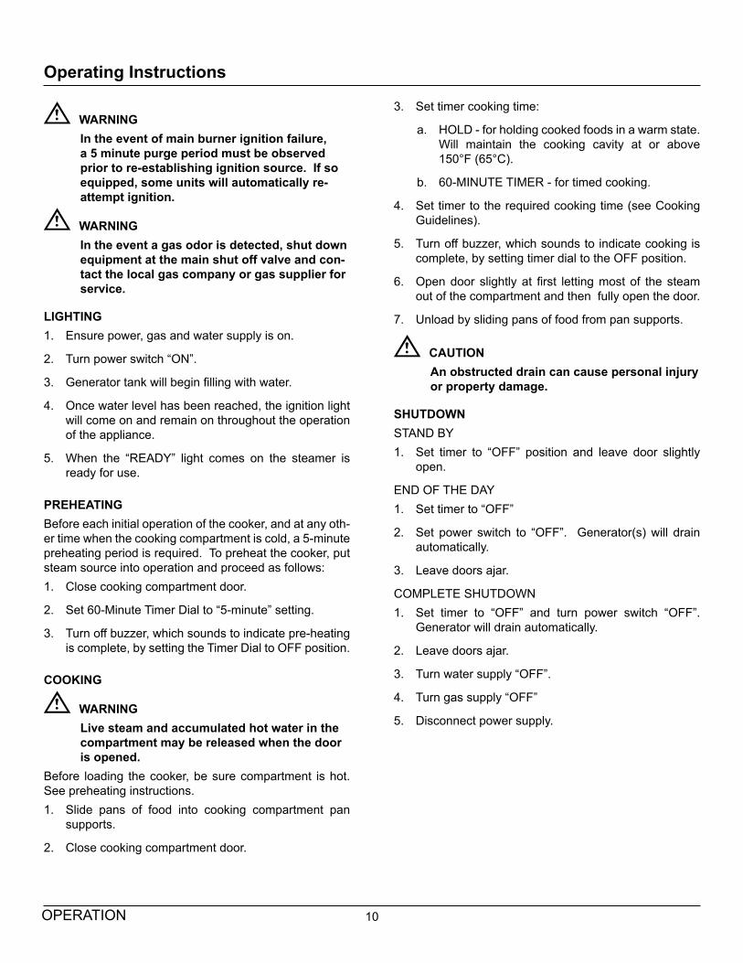
FILTER SYSTEM INSTALLATION SET-UP1. Remove sanitary cap from cartridge. Install cartridge
with a quarter turn to the right until cartridge comes to a complete stop. (A “click” is heard). See “Figure 3”.
2. It is recommended that cartridges be replaced regularly, at no more than six-month inter-vals, to be assured of optimum performance. See “Figure 4”.
To replace cartridge:a. Shut off inlet water.
b. Open a downstream valve to relieve pressure.
c. Unscrew the cartridge in the direction shown in the illustration and discard.
d. Lubricate o-ring of new cartridge with water. DO NOT use petroleum jelly.
e. Install by turning new cartridge toward the right until it comes to a complete stop. DO NOT over tighten. (Never use tools to tighten a cartridge).
f. Turn on inlet valve, bleed air through a down-stream valve until water appears clear, and check for leaks. System is now ready for use.
Figure 3
Figure 4

8INSTALLATION
Filter Change Procedure
NOTE: This system is equipped with an internal shut-off valve.
1. Turn cartridge slowly to the left, about 1/4 turn, until it stops (when arrows line up). At this position, both inlet and outlet ports are closed and water pressure has been relieved.
2. Pull used cartridge straight down and discard. Note: There may be a small amount of residual water drain-age after pressure is relieved and during cartridge removal.
3. Moisten o-ring with a food grade lubricant and push new cartridge into filter head. Turn cartridge 1/4 turn to the right until it stops (when arrows line up). Top surface of cartridge will become flush with bottom of the head when fully engaged.
4. Open downstream valve (if installed) and flush new filter cartridge for two minutes, expelling any trapped air and carbon fines. Water may run cloudy with air but will quickly clear.
Figure 5

9 INSTALLATION
Performance Check
WARNINGThe steamer and its parts are hot. Use care when operating, cleaning or servicing the steamer. The cooking compartment contains live steam. Stay clear while opening door.
Once the steamer is installed and all mechanical connec-tions have been made, thoroughly test the steamer before operation.1. Check that proper water, drain and electrical and gas
connections have been made.
2. Turn main power switch “ON”. After approximately 14 minutes, the “READY” light should come on and should remain on, indicating that the water tempera-ture is approximately 200° Fahrenheit (93° Celsius).
3. Check that “IGNITION” light comes on when the burn-er pilot is ON.
4. When the “READY” light comes on, set timer to the “5 minute” position. With door open, observe that no steam is entering the compartment and that the “COOKING” light is OFF.
5. Close compartment door. The “COOKING” light should now be illuminated and steam should be heard entering the compartment after about 45 sec-onds. “READY LIGHT” is OFF.
6. The tempering tank does not discharge to drain un-til the water in the top of the tank reaches 130°F or the unit is shut off and the generators are allowed to drain.
7. Open compartment door and observe that steam supply to chamber is cut off and the “COOKING” light goes “OFF” and “READY LIGHT” is OFF.
8. Close compartment door and let cooking cycle finish. When the timer returns to “0” position, a buzzer will sound signaling the end of the cooking cycle. Buzzer must be manually turned off by setting the timer to its “OFF” position.
10OPERATION
Operating Instructions
WARNINGIn the event of main burner ignition failure, a 5 minute purge period must be observed prior to re-establishing ignition source. If so equipped, some units will automatically re-attempt ignition.
WARNINGIn the event a gas odor is detected, shut down equipment at the main shut off valve and con-tact the local gas company or gas supplier for service.
LIGHTING1. Ensure power, gas and water supply is on.
2. Turn power switch “ON”.
3. Generator tank will begin filling with water.
4. Once water level has been reached, the ignition light will come on and remain on throughout the operation of the appliance.
5. When the “READY” light comes on the steamer is ready for use.
PREHEATINGBefore each initial operation of the cooker, and at any oth-er time when the cooking compartment is cold, a 5-minute preheating period is required. To preheat the cooker, put steam source into operation and proceed as follows:1. Close cooking compartment door.
2. Set 60-Minute Timer Dial to “5-minute” setting.
3. Turn off buzzer, which sounds to indicate pre-heating is complete, by setting the Timer Dial to OFF position.
COOKING
WARNINGLive steam and accumulated hot water in the compartment may be released when the door is opened.
Before loading the cooker, be sure compartment is hot. See preheating instructions.1. Slide pans of food into cooking compartment pan
supports.
2. Close cooking compartment door.
3. Set timer cooking time:
a. HOLD - for holding cooked foods in a warm state. Will maintain the cooking cavity at or above 150°F (65°C).
b. 60-MINUTE TIMER - for timed cooking.
4. Set timer to the required cooking time (see Cooking Guidelines).
5. Turn off buzzer, which sounds to indicate cooking is complete, by setting timer dial to the OFF position.
6. Open door slightly at first letting most of the steam out of the compartment and then fully open the door.
7. Unload by sliding pans of food from pan supports.
CAUTIONAn obstructed drain can cause personal injury or property damage.
SHUTDOWNSTAND BY1. Set timer to “OFF” position and leave door slightly
open.
END OF THE DAY1. Set timer to “OFF”
2. Set power switch to “OFF”. Generator(s) will drain automatically.
3. Leave doors ajar.
COMPLETE SHUTDOWN1. Set timer to “OFF” and turn power switch “OFF”.
Generator will drain automatically.
2. Leave doors ajar.
3. Turn water supply “OFF”.
4. Turn gas supply “OFF”
5. Disconnect power supply.

11 OPERATION
Operating Instructions
Frequently check that the compartment drain and plumb-ing is free of all obstructions. Never place food contain-ers, food or food portion bags in the cooking compart-ment in such a way that the compartment drain becomes obstructed.Each compartment is equipped with a removable drain screen. Frequently check the drain screen for accumula-tion of food particles. Should food particles accumulate against, or clog the drain screen, remove it, clean it thor-oughly and then replace it in its original position.
SHUT-DOWN PROCEDURENo shut-down procedure is required for the cooker except to check that both timer dials are in the OFF position and that both compartment doors are open. When all cooking has been completed for the day, the steam source must be shut off.Complete Shutdown1. Set timer to “OFF” and turn power switch “OFF”.
Steam generators will drain automatically.
2. Turn water supply “OFF”.
3. Close manual gas shut off valve.
4. Disconnect power supply.
CLEANINGAfter each period of daily operation (more frequently as required to maintain cleanliness), the cooker should be thoroughly cleaned by completing the following steps:1. Remove left and right side pan supports by lifting up
and off mounting studs. Remove the drain screen in the rear of the compartment. Wash with a mild deter-gent. Rinse and set aside for reassembly.
2. Wash cooking compartment interior using a mild de-tergent and water. Rinse and dry thoroughly.
3. Replace pan supports and drain screen in compart-ment and leave door open.
DRAINAGECooking Compartment DrainageThe bottom of the cooking compartment is angled slightly toward the rear of the unit. This assures that any conden-sate build-up or spills will be directed toward the drain, which is located at the rear bottom center of the cooking compartment. Any liquid exiting the cooking compart-ment runs down the cooking compartment drain tube and into the condensate tempering tank.Drip/Spill Trough DrainageThe Pressureless Steam Cooker has a drip/spill trough below the cooking compartment door. It will catch any condensate gathering on the front of the unit when the door is opened.
WARNINGThe steamer and its parts are hot. Use care when operating, cleaning or servicing the steamer. The cooking compartment contains live steam. Stay clear when opening door.
CAUTIONAn obstructed drain can cause personal injury or property damage.
12OPERATION
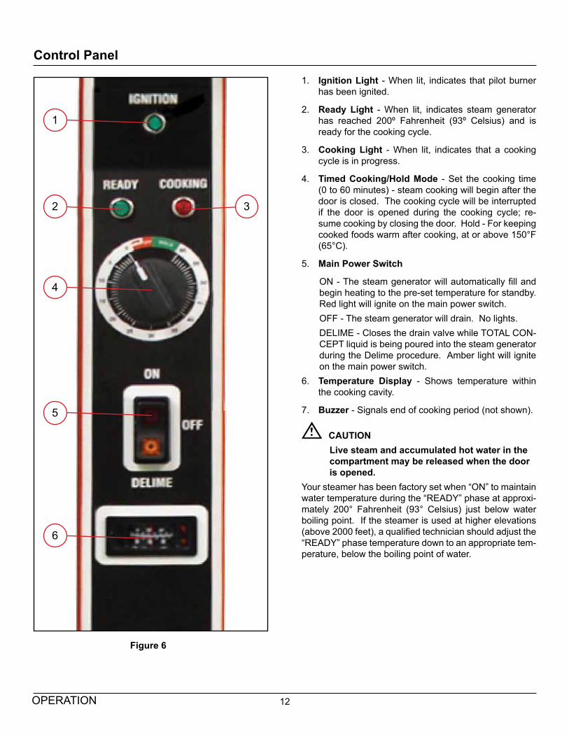
Control Panel
1. Ignition Light - When lit, indicates that pilot burner has been ignited.
2. Ready Light - When lit, indicates steam generator has reached 200º Fahrenheit (93º Celsius) and is ready for the cooking cycle.
3. Cooking Light - When lit, indicates that a cooking cycle is in progress.
4. Timed Cooking/Hold Mode - Set the cooking time (0 to 60 minutes) - steam cooking will begin after the door is closed. The cooking cycle will be interrupted if the door is opened during the cooking cycle; re-sume cooking by closing the door. Hold - For keeping cooked foods warm after cooking, at or above 150°F (65°C).
5. Main Power Switch
ON - The steam generator will automatically fill and begin heating to the pre-set temperature for standby. Red light will ignite on the main power switch.OFF - The steam generator will drain. No lights.DELIME - Closes the drain valve while TOTAL CON-CEPT liquid is being poured into the steam generator during the Delime procedure. Amber light will ignite on the main power switch.
6. Temperature Display - Shows temperature within the cooking cavity.
7. Buzzer - Signals end of cooking period (not shown).
CAUTIONLive steam and accumulated hot water in the compartment may be released when the door is opened.
Your steamer has been factory set when “ON” to maintain water temperature during the “READY” phase at approxi-mately 200° Fahrenheit (93° Celsius) just below water boiling point. If the steamer is used at higher elevations (above 2000 feet), a qualified technician should adjust the “READY” phase temperature down to an appropriate tem-perature, below the boiling point of water.
Figure 6
1
2
4
3
5
6

13 OPERATION
Test Kitchen Bulletin
Pressureless Cooker - Facts On Parade1. Frozen vegetables should always be cooked in per-
forated 12” x 20” x 2 1/2“ pans 7 1/2 lbs. (34 kg) maximum per pan.
2. Frozen entrees should be underlined with a perforat-ed pan for best results. If they are defrosted first, the heating time will be decreased.
3. Fresh foods may also be cooked in this unit. Veg-etables and other foods where the stock is not to be retained should be cooked in perforated 12” x 20” x 2-1/2” pans for the most nutritious results.
4. There is a safety microswitch on the door which shuts off the steam each time the door is opened if the unit is in the cooking cycle.
5. Total cooking time will vary depending on the load, even though the timer setting is the same.
6. All foods, except cakes and pastry, can be cooked in a steam cooking unit.
7. Steam cooked meals have greater nutritional value since they retain most of their vitamins and minerals.
8. Because foods are cooked faster by the higher tem-peratures of steam cooking, they can be prepared closer to serving time, insuring maximum freshness.
9. Steam cooked foods have a higher percent yield more portions per dollar spent.
10. Food may be served from the same pan in which it is steam cooked, thus reducing food breakage since there is no extra handling or transferring of food from cooking pans to serving pans. It also reduces pot washing tasks.
11. Some important advantages of steam cooking are la-bor saving, reduced operating costs, space saving, and the lifting of heavy stock pots is eliminated.
12. Rice and spaghetti products, if thoroughly wet at the start of the cooking process, are very easily prepared.
13. Food such as potatoes, poultry, seafood, and some meats may be blanched in the steam cooker, thus re-ducing the total cooking time and grease absorption.
14. The steam cooker will loosen foods burned on pans making washing easier.
15. Solid pans are recommended when liquid is to be re-tained and perforated pans when the liquid is not to be retained.
16. Eggs may be cooked out of the shell if they are to be chopped which eliminates peeling after steaming.
17. The steam cooker can be opened during the cooking period to add or remove items.
14OPERATION
Cooking Tips
STEAM COOKING Your steamer efficiently cooks vegetables or other foods for immediate serving. Steam cooking should be carefully time controlled. Keep hot food holding time to a minimum to produce the most appetizing results. Prepare small batches, cook only enough to start serving, then cook ad-ditional amounts to meet demand. Separate frozen foods into smaller pieces to allow more efficient cooking.Use a pan cover for pre-cooked frozen dishes that cannot be cooked in the covered containers in which they are packed if they require more than 15 minutes of cooking time. When cover is used, approximately one-third ad-ditional cooking time is necessary.Cooking time for frozen foods depends on amount of de-frosting required. If time permits, allow frozen foods to partially thaw overnight in a refrigerator. This will reduce their cooking time.
PREPARATIONPrepare vegetables, fruits, meats, seafood and poul-try normally by cleaning, separating, cutting, removing stems, etc. Cook root vegetables in a perforated pan un-less juices are being saved. Liquids can be collected in a solid 12” x 20” pan placed under a perforated pan. Per-forated pans are used for frankfurters, wieners and similar items when juices do not need to be preserved. Solid pans are good for cooking puddings, rice and hot break-fast cereals. Vegetables and fruits are cooked in solid pans in their own juices. Meats and poultry are cooked in solid pans to preserve their own juices or to retain broth. Canned foods can be heated in their opened cans (cans placed in 12” x 20” solid pans) or the contents may be poured into solid pans.
PANSThe steamer compartment is designed to accept combi-nations of the pan of 12” x 20” (either solid or perforated) as shown on the following table.
Depth of Pan Number of Pans per Compartment
1” 10
2-½” 5
4” 3
6” 2

15 OPERATION
Cooking Guide
The cooking times indicated in this list are based on a preheated cooking compartment. Preheat time for the Eco-Tech Plus Steamer is approximately 15 minutes.
ItemApprox.
Frozen Wt. Per Pan
Recommended Pan Size 12” x 20”
Perforated
Number of Pans
Timer Settings in
Minutes
Approx. No. Cooked Servings Per Pan
FROZEN VEGETABLES
Asparagus Spears 7 1/2 lbs (3.4 kg) 2-1/2” (65mm) 1-5 12-15 30
3 oz. (85 g)
Beans, Green Regular 6 lbs (2.7 kg) 2-1/2” (65mm) 1-5 10-15 25
3 oz. (85 g)Beans, Green French Cut
6 lbs (2.7 kg) 2-1/2” (65mm) 1-5 5-7 25
3 oz. (85 g)
Beans, Lima 7 1/2 lbs (3.4 kg) 2-1/2” (65mm) 1-5 12-15 30
3 oz. (85 g)
Broccoli 6 lbs
(2.7 kg)2-1/2” (65mm) 1-5 4-6 25
3 oz. (85 g)
Brussel Sprouts 7 1/2 lbs (2.7 kg) 2-1/2”(65mm) 1-5 10-15 30
3 oz. (85 g)
Carrots 6 lbs (2.7 kg) 2-1/2” (65mm) 1-5 10-15 25
3 oz. (85 g)
Cauliflower 6 lbs (2.7 kg) 2-1/2” (65mm) 1-5 7-12 25
3 oz. (85 g)
Corn-Cut 7 1/2 lbs 3.4 kg) 2-1/2” (65mm) 1-5 8-12 30
3 oz. (85 g)
Mixed Vegetables 7 1/2 lbs (3.4 kg) 2-1/2” (65mm) 1-5 8-12 30
3 oz. (85 g)
Peas (Loose) 7 1/2 lbs (3.4kg) 2-1/2” (65mm) 1-5 3-5 30
3 oz. (85 g)
Spinach 9 lbs (4kg) 2-1/2” (65mm) 1-5 Must be
defrosted30
3 oz. (85 g)
Squash 12 lbs (5.4 kg) 2-1/2”(65mm) 1-5 Must be
defrosted50
3 oz. (85 g)
FROZEN PREPARED ENTREESLobster Tails 6-8 oz. (170-255 g)
7-8 lbs (3.2-3.6 kg) 2-1/2” (65mm) 1-5 15-25 15
6 oz. (170 g)
Shrimp, C.D.P. 16-20 lbs (7-9 kg) 2-1/2” (65mm) 1-5 8-11 75
3 oz. (85g)
Shrimp, Green 16-20 lbs (7-9 kg) 2-1/2” (65mm) 1-5 11-15 50
3 oz. (85 g)
Bulk Pack, Frozen 3 1/2-4 lbs (1.6-1.8 kg) 2-1/2” (65mm) 1-5 35-45 10
6 oz. (170 g)
Bulk Pack, Defrosted 3 1/2-4 lbs (1.6-1.8 kg) 2-1/2” (65mm) 1-5 25-35 10
6 oz. (170 g)

16OPERATION
ItemApprox.
Frozen Wt. Per Pan
Recommended Pan Size 12” x 20”
Perforated
Number of Pans
Timer Settings in
Minutes
Approx. No. Cooked Servings Per Pan
VEGETABLESBeans, Snap Green or Waxed
6 lbs (2.7 kg) 2-1/2” (65mm) 1-5 18-22 25-30
3 oz. (85 g)
Beets, 2” Diameter 7 1/2 lbs (3.4 kg) 2-1/2” (65mm) 1-5 40-50 30-35
3 oz. (85 g)Broccoli, Stalks1/2-3/4”
6 lbs (2.7 kg) 2-1/2” (65mm) 1-5 14-18 25-30
3 oz. (85 g)
Carrots, Sliced 9 lbs (4 kg) 2-1/2” (65mm) 1-5 18-21 35-40
3 oz. (85 g)Cauliflower, Trimmed 1-1/2” to 2”
6 lbs (2.7 kg) 2-1/2” (65mm) 1-5 12-16 30-35
3 oz. (85 g)Corn on Cob Husked 1 dozen 2-1/2” (65mm) 1-5 10-15 12Cabbage 1/4-1/6 of Head, Cored
5 lbs (2.25 kg) 2-1/2” (65mm) 1-5 14-18 15-20
4 oz. (115 g)
Onions, 2” Diameter6 lbs
(2.7 kg)2-1/2” (65mm) 1-5 20-25 25-30
4 oz. (115 g)
Peas, Shelled 5 lbs (2.25 kg) 2-1/2” (65mm) 1-5 5-6 25-30
3 oz. (85 g)Potatoes, French Fry Cut
10 lbs (4.5 kg) 2-1/2” (65mm) 1-5 18-21 50
3 oz. (85 g)
Potatoes, Regular Cut, 3”
10 lbs (4.5 kg) 2-1/2” (65mm) 1-5 35-40 50
3 oz. (85 g)
Spinach, Cleaned Cut 3 lbs (1.4 kg) 2-1/2” (65mm) 1-5 3-5 10-12
3 3/4 oz. (105 g)Squash, Summer, Sliced 1” thick
7 lbs (3.2 kg) 2-1/2” (65mm) 1-5 7-10 30-35
3 oz. (85 g)Squash, Winter Peeled
9 lbs (4 kg) 2-1/2” (65mm) 1-5 10-15 25-30
3 oz. (85 g)
Turnip, Dice 5 lbs (2.25 kg) 2-1/2” (65mm) 1-5 28-32 20-25
4 oz. (115 g)
CANNED VEGETABLES
Canned, Vegetables 7 lbs. (3.2 kg) 2-1/2” (65mm) 1-5 5-10 25-30
3 oz. (85 g)MISCELLANEOUSEggs, in Shell 3 dozen 2-1/2” (65mm) 1-5 9-11 36 - 1 Egg EachEggs, out of Shell 4 dozen 2-1/2” (65mm) 1-5 6-8 48 - 1 Egg Each
Rice 4 lbs (1.8 kg) 2-1/2” (65mm) 1-2 18-22 60-65
3 oz. (85 g)
Spaghetti 3 lbs (1.4 kg) 2-1/2” (65mm) 1-2 18-22 40-45
4 oz. (115 g)
Cooking Guide
17 OPERATION
ItemApprox.
Frozen Wt. Per Pan
Recommended Pan Size 12” x 20”
Perforated
Number of Pans
Timer Settings in
Minutes
Approx. No. Cooked Servings Per Pan
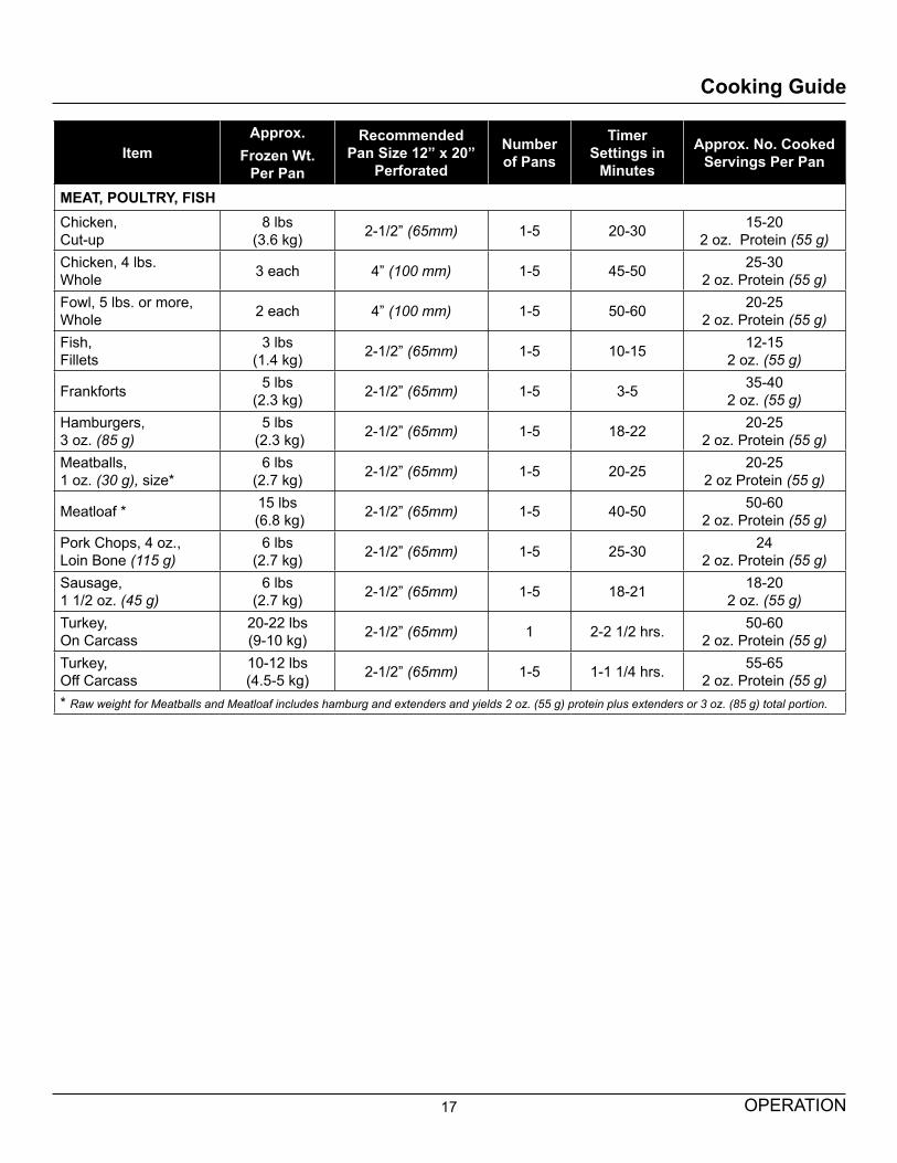
MEAT, POULTRY, FISHChicken, Cut-up
8 lbs (3.6 kg) 2-1/2” (65mm) 1-5 20-30 15-20
2 oz. Protein (55 g)Chicken, 4 lbs. Whole 3 each 4” (100 mm) 1-5 45-50 25-30
2 oz. Protein (55 g)Fowl, 5 lbs. or more, Whole 2 each 4” (100 mm) 1-5 50-60 20-25
2 oz. Protein (55 g)Fish, Fillets
3 lbs (1.4 kg) 2-1/2” (65mm) 1-5 10-15 12-15
2 oz. (55 g)
Frankforts 5 lbs (2.3 kg) 2-1/2” (65mm) 1-5 3-5 35-40
2 oz. (55 g)Hamburgers, 3 oz. (85 g)
5 lbs (2.3 kg) 2-1/2” (65mm) 1-5 18-22 20-25
2 oz. Protein (55 g)Meatballs,1 oz. (30 g), size*
6 lbs (2.7 kg) 2-1/2” (65mm) 1-5 20-25 20-25
2 oz Protein (55 g)
Meatloaf * 15 lbs (6.8 kg) 2-1/2” (65mm) 1-5 40-50 50-60
2 oz. Protein (55 g)Pork Chops, 4 oz., Loin Bone (115 g)
6 lbs (2.7 kg) 2-1/2” (65mm) 1-5 25-30 24
2 oz. Protein (55 g)Sausage, 1 1/2 oz. (45 g)
6 lbs (2.7 kg) 2-1/2” (65mm) 1-5 18-21 18-20
2 oz. (55 g)Turkey, On Carcass
20-22 lbs (9-10 kg) 2-1/2” (65mm) 1 2-2 1/2 hrs. 50-60
2 oz. Protein (55 g)Turkey, Off Carcass
10-12 lbs (4.5-5 kg) 2-1/2” (65mm) 1-5 1-1 1/4 hrs. 55-65
2 oz. Protein (55 g)* Raw weight for Meatballs and Meatloaf includes hamburg and extenders and yields 2 oz. (55 g) protein plus extenders or 3 oz. (85 g) total portion.
Cooking Guide
18MAINTENANCE
Cleaning & Preventative Maintenance
A good preventive maintenance program begins with the daily cleaning procedure. The following paragraphs set out the minimum preventive maintenance procedures that must be completed periodically to assure continued trouble-free operation of the steamer.
CAUTIONUnder no circumstances should hardware (or parts) be replaced with a different length, size, or type other than as specified in the parts list. The hardware used in the cooker has been selected or designed specifically for its application, and the use of other hardware may damage the equipment and will void any warranty.
WARNINGDisconnect the power supply to the appliance before cleaning or servicing.
WARNINGThe steamer and its parts are hot. Use care when operating, cleaning or servicing the steamer. The cooking compartment contains live steam. Stay clear when opening door.
CLEANINGDailing CleaningAt the end of each day, or between cooking cycles if nec-essary:1. Turn main power switch OFF.
2. Remove pans and racks from compartment and wash in sink.
3. Wash compartment interior with clean water.
4. Use warm soapy water with a cloth or sponge to clean exposed bead of door gasket, rinse with warm clear water and wipe with a dry cloth.
Wipe surfaces which touch door gasket with a cloth or sponge and warm soapy water, rinse with warm clear water and wipe with a dry cloth. Do not apply food oils or petroleum solvents or lubricants directly to door gasket or surfaces which touch door gasket.
5. Remove drain screen from inside compartment drain. Using a plastic bottle brush and mild detergent, clean inside the drain opening ensuring there is no food residue or blockage. Clean the drain screen and re-place in its original position.
6. Leave door slightly open when steamer is not in use.
CAUTIONDo not use cleaning agents that are corrosive.
NOTICEContact the factory, the factory representa-tive or a local service company to perform maintenance and repairs should the appliance malfunction. Refer to warranty terms.
Weekly, or more often if necessary:1. Clean exterior with a damp cloth and polish with a soft
dry cloth.
2. Use a non-abrasive cleaner to remove discolorations.
3. Clean around burner air mixer and orifice if lint has accumulated. Side cover must be removed to clean this area.
Monthly:1. Clean around burner air mixers, louvered panels if
grease or lint has accumulated.
Following daily and periodic maintenance procedures will enhance long-life for your equipment. Climatic conditions - salt air - may require more thorough and frequent clean-ing otherwise the life of the equipment could be adversely affected. It is NOT RECOMMENDED to use cleaning agents that are corrosive.Use of cleaning agents that contain chloride, acids or salts which are corrosive may cause pitting and corrosion when used over a period of time; this will reduce the life of the appliance. Should pitting or corrosion occur, this is not covered by warranty.Follow the recommended cleaning instructions. Use a mild detergent, warm water and rinse thoroughly.NEVER SPRAY WATER INTO ELECTRIC CONTROLS OR LOUVERS.

19 MAINTENANCE
Cleaning & Preventative Maintenance
Stainless SteelTo remove normal dirt, grease or product residue from stainless steel, use ordinary soap and water (with or with-out detergent) applied with a sponge or cloth. Dry thor-oughly with a clean cloth. Never use vinegar or any cor-rosive cleaner.To remove grease and food splatters or condensed va-pours that have baked on the equipment, apply cleanser to a damp cloth or sponge and rub cleanser on the metal in the direction of the polishing lines on the metal. Rub-bing cleanser as gently as possible in the direction of the polished lines will not mar the finish of the stainless steel. NEVER RUB WITH A CIRCULAR MOTION.Soil and burnt deposits which do not respond to the above procedure can usually be removed by rubbing the sur-face with SCOTCH-BRITE scouring pads or STAINLESS scouring pads. DO NOT USE ORDINARY STEEL WOOL as any particles left on the surface will rust and further spoil the appearance of the finish. NEVER USE A WIRE BRUSH, STEEL SCOURING PADS (EXCEPT STAIN-LESS), SCRAPER, FILE OR OTHER STEEL TOOLS. Surfaces which are marred collect dirt more rapidly and become more difficult to clean. Marring also increases the possibility of corrosive attack. Refinishing may then be required.To Remove Heat TintDarkened areas sometimes appear on the stainless steel surface where the area has been subjected to excessive heat. These darkened areas are caused by thickening of the protective surface of the stainless steel and are not harmful. Heat tint can normally be removed by the forego-ing, but tint which does not respond to this procedure calls for a vigorous scouring in the direction of the polish lines using SCOTCH-BRITE scouring pads or a STAINLESS scouring pad in combination with a powdered cleanser. Heat tint action may be lessened by not applying or by reducing heat to equipment during slack periods.
DELIMINGMonthly Removal of Scale DepositsIt is recommended that your steamer be delimed once a month, or more often if necessary.Should your steamer develop a heavy build-up of lime scale deposits, use the TOTAL CONCEPT TREATMENT KIT available from your authorized service agent.Before beginning deliming procedures, ensure that water is not overflowing into the cooking compartment.Deliming ProceduresBoth generators must be delimed individually.
WARNINGRead and follow instructions on the TOTAL CONCEPT bottle. Use plastic or rubber gloves to avoid skin contact. If TOTAL CON-CEPT comes in contact with skin, rinse with clean water.
CAUTIONDo not open deliming caps when unit is in operation. Do not open or close compartment doors when deliming caps are not in place.
CAUTIONDo not open or close compartment doors or operate unit when deliming caps are not in place.
1. Turn the power switch “OFF” for three minutes, allow-ing the generators to completely empty.
2. Turn the power switch to the “DELIME” position.
3. Remove caps located on top right of steamer (left cap for top generator, right cap for bottom generator. Us-ing a funnel and pouring slowly to avoid spilling, pour one quart (0.95 liters) of Market Forge’s Total Con-cept deliming solution into each generator.
4. Replace the deliming caps and tighten. Turn power switch to “ON” for five minutes allowing the generator to completely fill.
5. Turn the power switch to the “DELIME” position. Un-screw the deliming caps and add one quart (0.05 li-ters) of clean water for gas units, 1/2 quart (0.48 li-ters) for electric units.
6. Replace the deliming caps and tighten. Turn the power switch “ON” for 30 minutes.
7. Flush the generators three times. Turn power switch to “OFF” for three minutes and then “ON” for five min-utes.
WARNINGWhen this appliance is installed with cast-ers and is connected to the supply piping by means of a connector for moveable appli-ances, a restraint to prevent damage to the connector or quick disconnect device should have been installed. If disconnection of the restraint is necessary, reconnect this restraint after the appliance has been returned to its originally installed position.